BNWAS
BNWAS does not ask whether the officer of the watch is competent — it only asks whether someone has touched a reset button recently, which is why a bridge team can defeat its purpose entirely by leaving a weighted object on the reset key.
Read more — BNWAS explained ▾
What this type is
The Bridge Navigational Watch Alarm System monitors whether the officer of the watch is present and active on the bridge, escalating through a defined alarm sequence if no activity is detected within a set interval. It is not a fatigue or competence monitor; it detects only physical inactivity at the console — no button press, no motion sensor trigger, no bridge equipment interaction within the timer window. SOLAS makes it mandatory precisely because incapacitation or falling asleep on watch has caused groundings that no other bridge system was designed to catch.

Main components
- Reset points — dedicated buttons or motion sensors positioned around the bridge so the OOW can reset the timer from the normal watchkeeping positions.
- Timer/logic unit — runs the adjustable 3-12 minute inactivity interval and the alarm escalation sequence.
- Stage 1 alarm — visual/audible alert on the bridge itself, giving the OOW a short window to reset.
- Stage 2 alarm — extends the alert, often to a location the OOW would need to move to reset, so a genuinely present but preoccupied officer still resets it.
- Stage 3 backup alarm — sounds in the master's cabin and/or designated officer's cabin(s), and on some installations additional crew spaces, when stages 1 and 2 are not acknowledged.
Selection and sizing
The main selection variable is reset point layout, not the electronics — the points must cover every position the OOW legitimately works from (chart table, radar, bridge wings on vessels where wing watchkeeping is normal) so a genuinely attentive officer is never falsely alarmed for being at a different console. The backup alarm routing (which cabins, which public spaces) must match the vessel's actual watch and manning structure.
Regulations and class
SOLAS Chapter V, Regulation 19, requires BNWAS on all vessels of 150 gross tonnage and upward on international voyages, phased in by vessel type and build date. Performance standards are set out in IMO resolution MSC.128(75), covering the timer ranges, alarm stages and escalation timing. Class survey checks the fitted system carries type approval to this standard and that the alarm sequence and cabin routing match what was tested at commissioning.
Typical faults
- Reset button wedged or taped down — defeats the entire system while showing no fault, the single most common documented failure mode.
- Motion-sensor reset points triggered by routine bridge movement unrelated to actual watchkeeping, masking genuine inactivity.
- Stage 3 cabin alarm wiring not tested after a crew cabin reassignment, so the backup alert goes to an empty room.
- Timer interval left at a setting inappropriate for the vessel's operation, causing either alarm fatigue or too long a gap before escalation.
What to look for in a supplier
- Type approval to MSC.128(75) with the certificate matching the exact model installed.
- Reset point layout proposal based on the vessel's actual bridge arrangement, not a generic template.
- Backup alarm routing configurable to the vessel's manning and cabin layout.
- Commissioning test report confirming every stage and every cabin alarm was verified, not just stage 1.
Test BNWAS by letting it run through to stage 3 during commissioning and after any crew accommodation change — a system that has only ever been reset at stage 1 has never proven its backup alarm actually reaches anyone.
7 manufacturers · 7 models
Alphatron Marine
1
- Sensor, camera or input failure causes missing data, blank images or channel alarms
- Power-supply, UPS or network faults cause system restart, loss of recording or unavailable remote status
- Storage-media or recorder faults cause gaps in retained data or failed self-tests
- Incorrect time, configuration or interface data causes inconsistent records or false alarms
- Control, acknowledgment or communication faults cause unavailable watchkeeping or security functions
- Three‑stage alarm hierarchy meets IMO Resolution requirements out of the box
- Can operate both fully integrated with AlphaBridge systems and independently, offering flexibility for retrofits
- IMO approved (Resolution A.938(23)) ensuring regulatory compliance on international voyages
- Compact software architecture simplifies installation on existing bridge consoles
- Relies heavily on the vessel’s data bus; a failure in the bus can disable alarm functions
- Sensor detection range is limited, requiring careful placement to guarantee coverage of all bridge workstations
- Alarm escalation timing has been reported as slower than some competitor systems, potentially delaying crew response
AMI Marine
1
- Sensor, camera or input failure causes missing data, blank images or channel alarms
- Power-supply, UPS or network faults cause system restart, loss of recording or unavailable remote status
- Storage-media or recorder faults cause gaps in retained data or failed self-tests
- Incorrect time, configuration or interface data causes inconsistent records or false alarms
- Control, acknowledgment or communication faults cause unavailable watchkeeping or security functions
- Meets mandatory IMO SOLAS BNWAS requirement at a lower purchase cost
- Three‑stage alarm logic provides graduated alerts for watchkeeper inactivity
- Compact design suitable for retrofitting on existing bridge consoles
- Sensor reliability reported as inconsistent, potentially leading to false alarms or missed alerts
- Limited global service and support network may increase downtime for vessels operating far from major ports
- Configuration interface is complex, requiring experienced personnel for proper setup
Consilium Marine
1
- Sensor, camera or input failure causes missing data, blank images or channel alarms
- Power-supply, UPS or network faults cause system restart, loss of recording or unavailable remote status
- Storage-media or recorder faults cause gaps in retained data or failed self-tests
- Incorrect time, configuration or interface data causes inconsistent records or false alarms
- Control, acknowledgment or communication faults cause unavailable watchkeeping or security functions
- IMO‑approved 3‑stage alarm escalation ensures regulatory compliance
- Compact design suitable for limited bridge space
- Adjustable motion sensor sensitivity for different vessel motions
- Simple mechanical reset button for quick manual acknowledgement
- Proven field record on a variety of passenger and offshore vessels
- Motion sensor can drift over time, requiring periodic recalibration
- Reset button membrane may wear out after many activations
- Alarm relay has reported failures in high‑vibration installations
- Limited built‑in diagnostics compared with newer networked BNWAS units
- Correct sensor placement is critical; poor mounting reduces reliability
JRC
1- Sensor, camera or input failure causes missing data, blank images or channel alarms
- Power-supply, UPS or network faults cause system restart, loss of recording or unavailable remote status
- Storage-media or recorder faults cause gaps in retained data or failed self-tests
- Incorrect time, configuration or interface data causes inconsistent records or false alarms
- Control, acknowledgment or communication faults cause unavailable watchkeeping or security functions
- Three‑stage monitoring meets IMO SOLAS BNWAS requirements out of the box
- Full integration with existing JRC bridge alarm panels simplifies wiring and configuration
- IMO approved (SOLAS) ensures regulatory compliance for passenger and cargo vessels
- Modular design allows retrofitting on new builds or existing ships without major modifications
- Reported sensor zone coverage gaps can leave blind spots in larger bridge layouts
- Alarm timer adjustment may be cumbersome, requiring specialist service to fine‑tune intervals
- Indicator LED failures have been noted, potentially masking alarm status until repaired
- Proprietary interface limits compatibility with non‑JRC bridge systems
Kelvin Hughes
1- Sensor, camera or input failure causes missing data, blank images or channel alarms
- Power-supply, UPS or network faults cause system restart, loss of recording or unavailable remote status
- Storage-media or recorder faults cause gaps in retained data or failed self-tests
- Incorrect time, configuration or interface data causes inconsistent records or false alarms
- Control, acknowledgment or communication faults cause unavailable watchkeeping or security functions
- IMO‑approved, meeting SOLAS Chapter V watch alarm requirements
- Three‑stage escalation (warning, alarm, emergency) provides clear progression of alerts
- Seamless integration with Kelvin Hughes bridge consoles and radar suites
- Highly configurable thresholds and response times to suit different vessel operations
- Proven track record on passenger ships and offshore support vessels
- Integration can be problematic with non‑Kelvin Hughes bridge alarm panels
- Configuration interface is complex, requiring specialist training
- Sensor reliability issues reported in harsh marine environments
- Limited third‑party compatibility compared with some open‑architecture BNWAS solutions
- Upgrades may require firmware coordination across the entire Kelvin Hughes suite
Netwave
1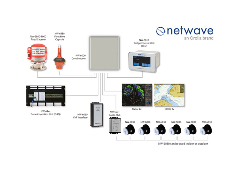
- Sensor, camera or input failure causes missing data, blank images or channel alarms
- Power-supply, UPS or network faults cause system restart, loss of recording or unavailable remote status
- Storage-media or recorder faults cause gaps in retained data or failed self-tests
- Incorrect time, configuration or interface data causes inconsistent records or false alarms
- Control, acknowledgment or communication faults cause unavailable watchkeeping or security functions
- IMO‑approved three‑stage compliance ensures regulatory acceptance
- Cost‑effective solution compared with many premium BNWAS units
- Can be integrated with Netwave VDR packages for a unified bridge safety system
- Simple user interface and straightforward installation on most vessel bridges
- Provides audible, visual and tactile alarms to cover multiple failure scenarios
- Alarm sensor must be precisely positioned; mis‑placement can cause false alarms or missed alerts
- Reported power‑supply sensitivity may require additional backup circuitry
- Alarm circuit board failures have been noted in field service reports
- Limited advanced diagnostics and remote monitoring features compared with higher‑end competitors
- No built‑in redundancy for the sensor module; relies on a single point of detection
SAM Electronics
1- Sensor, camera or input failure causes missing data, blank images or channel alarms
- Power-supply, UPS or network faults cause system restart, loss of recording or unavailable remote status
- Storage-media or recorder faults cause gaps in retained data or failed self-tests
- Incorrect time, configuration or interface data causes inconsistent records or false alarms
- Control, acknowledgment or communication faults cause unavailable watchkeeping or security functions
- Three‑stage alarm sequence provides graduated escalation for missed responses
- IMO approved and fully compliant with SOLAS Chapter V
- Seamless integration with SAM/Wärtsilä NACOS bridge suite for unified monitoring
- Modular design allows retro‑fit on existing vessels with minimal wiring changes
- Proven field record on a wide range of commercial ships
- Reported integration challenges when coupling with non‑SAM bridge systems
- Limited functionality in standalone mode; relies heavily on NACOS for full feature set
- Transition to Wärtsilä ownership has created short‑term support and spare‑parts uncertainties
- Higher upfront cost compared with basic, stand‑alone BNWAS units