"> Gyrocompass - Equipment Database

Gyrocompass

medium 13 models total

A gyrocompass finds true north mechanically or optically, independent of the earth's magnetic field, which is why it stays the primary heading reference on vessels 500 GT and above even though satellite compasses now exist as an alternative under the same SOLAS rule.

Read more — Gyrocompass explained

What Makes This Type

A gyrocompass derives true heading rather than magnetic heading, either from a spinning mass that precesses to align with the earth's rotation axis, or, in newer fibre-optic gyro (FOG) designs, from the Sagnac effect measured by laser light travelling in opposite directions around a coiled fibre. Both approaches are immune to magnetic deviation, which is the reason gyrocompass output, not the magnetic compass, feeds radar, ECDIS, autopilot and AIS. SOLAS Chapter V allows a satellite compass as an alternative heading reference on some vessel classes, but the spinning-mass and FOG gyrocompass remain the dominant fit because they keep working with no line of sight to satellites and are harder to spoof or jam than a GNSS-derived heading.
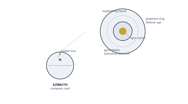
Gyrocompass, sensitive element and compass card
Cutaway of a gyrocompass showing the spin motor inside the floating gyrosphere, the surrounding phantom ring and supporting liquid, and the azimuth compass card with lubber line read by the follow-up shaft above.

Main Components

  • Master compass / sensor unit: the spinning rotor and its follow-up system in a conventional design, or the fibre-optic gyro assembly and processing electronics in a FOG unit.
  • Repeater compasses: transmit heading to bridge wings, steering stand and other positions from the master unit, historically by step-transmission, now often by serial data.
  • Speed and latitude correction input: conventional spinning-mass gyros need speed and latitude entered or fed automatically to correct for speed error and damping error, since the rotor's apparent north-seeking is distorted by the ship's own motion.
  • Power supply and standby battery: gyrocompasses take time to settle after a cold start, so continuity of power during a blackout matters more here than for most bridge equipment.

Selection and Sizing

Settling time after start-up, typically a few hours for a spinning-mass unit against a shorter interval for FOG designs, is a practical factor on vessels that shut the compass down in port. Accuracy is normally specified within about 0.5 to 1 degree of true heading depending on latitude and vessel speed, degrading at high latitude as the horizontal component of earth rotation the mechanism relies on shrinks. Interface requirements matter as much as the sensor itself: the unit has to output the heading data format that ECDIS, radar and the integrated bridge system on board actually expect.

Regulations and Class

SOLAS Chapter V, Regulation 19 requires vessels of 500 GT and above engaged on international voyages to carry a gyrocompass or equivalent heading device, with a heading repeater at the emergency steering position. Class rules require periodic testing of heading accuracy against an independent reference and functional testing of alarms for power loss and excessive heading error. Type approval under the relevant performance standard is required before the unit can be fitted as the primary compliant heading source.

Typical Faults

FaultConsequence
Speed/latitude correction not updated or wired incorrectlySteady-state heading error that grows with speed, feeding a wrong course into autopilot and radar
Follow-up system wear on spinning-mass unitsRepeater compasses drift out of agreement with the master, confusing cross-checks on the bridge
Power interruption during a blackoutFull re-settling period needed after restart, leaving the vessel without a true heading reference for hours at the worst possible time
FOG fibre coil degradation with ageSlow accuracy drift that is easy to miss without a scheduled comparison against GPS-derived course

What to Look for in a Supplier

  • Type approval certificate valid for the vessel's flag and trading pattern.
  • Confirmed data output protocol compatibility with the existing ECDIS, radar and autopilot rather than a unit needing a signal converter bolted on afterward.
  • Documented settling time and standby power arrangement suited to how the vessel actually operates in port.

Cross-check gyro heading against GPS course made good on a steady leg at least once a watch - a slow drift is invisible on the repeater alone but obvious the moment you compare it to an independent source.

9 manufacturers · 13 models

Raytheon Anschütz

3
Raytheon Anschütz Standard 20
Standard 20
Spinning mass gyro · Navigation Data / Sensor · Spinning mass gyrocompass
Technology
Spinning Mass
Settling time
3-5 hrs
Accuracy
0.5° secant lat
IMO Approved
ja
Common Failures & Inspection Points
  • Rotor bearing wear after 40,000+ hrs
  • Fluid level check required
  • Follow-up motor aging
Service: Traditional spinning mass. Requires periodic bearing and fluid checks.
Spare Parts: Raytheon Anschütz: Ersatzteile per Hersteller-Netzwerk. Lead time: 1-4 Wochen. Backup-Systeme an Bord pflichtgemäß.
Strengths
  • Proven reliability on a wide range of commercial vessels for decades
  • High heading accuracy (≈0.5° secant latitude) and low drift
  • Robust construction tolerates harsh marine environments and vibration
  • Integrated with Raytheon Anschütz navigation suites and autopilots
  • Standardised IMO D‑2 approval simplifies class certification
Weaknesses
  • Long warm‑up/settling time of 3–5 hours after power‑up
  • Mechanical wear of rotor bearings requires periodic inspection (≈40,000 h)
  • Fluid level and quality must be monitored regularly
  • Heavier and bulkier than modern solid‑state fiber‑optic gyros
  • Higher maintenance cost compared with non‑mechanical alternatives
Typical Vessels: TankerBulk carrierContainer shipPassenger ferryOffshore supply vessel
Certifications: IMO D-2ABSDNV GLLloyd's RegisterUSCG Type Approval
Decision Guide: Choose if you need a time‑tested, highly accurate gyrocompass on vessels where regular maintenance is acceptable and long warm‑up periods are not critical. Avoid if rapid start‑up, minimal upkeep, or weight savings are top priorities, in which case a solid‑state fiber‑optic or MEMS gyro would be preferable.
Use Cases: Standard 20 is typically installed as the primary heading source on new builds and retrofits of medium to large commercial ships, often paired with Raytheon Anschütz autopilot systems. It is favoured on routes where reliability and class approval outweigh the need for low‑maintenance solutions.
Horizon FOG
FOG gyro · Navigation Data / Sensor · Fiber Optic Gyro
Technology
Fiber Optic Gyro
Settling time
20 min
Accuracy
0.05° secant lat
IMO Approved
ja
Common Failures & Inspection Points
  • High replacement cost
  • Firmware dependency on Synapsis
  • Rare failures
Service: Premium FOG. Extremely low drift. 20+ year lifespan expected.
Spare Parts: Raytheon Anschütz: Ersatzteile per Hersteller-Netzwerk. Lead time: 1-4 Wochen. Backup-Systeme an Bord pflichtgemäß.
Strengths
  • Extremely low drift and high heading accuracy (0.05° secant latitude)
  • No moving parts – high reliability and long MTBF (>20 years expected)
  • Fully IMO type‑approved and class‑approved (DNV, ABS, LR)
  • Seamless integration with Raytheon Anschütz Synapsis bridge suite
  • Self‑diagnostic functions reduce maintenance downtime
Weaknesses
  • High initial purchase and replacement cost
  • Firmware tied to the proprietary Synapsis system – limited third‑party flexibility
  • Settling/alignment time of up to 20 minutes after power‑up
  • Spare parts and service can be expensive due to specialised optics
Typical Vessels: Container shipCrude oil tankerLNG/LPG carrierCruise linerOffshore supply vesselDP‑class vessel
Certifications: IMO Type ApprovalDNV ClassABSLR
Decision Guide: Choose if you need the highest heading accuracy and ultra‑low drift for long‑duration voyages, have an existing Raytheon Anschütz bridge suite (Synapsis), and can accommodate a higher capital cost. Avoid if budget constraints dominate, rapid start‑up is critical, or you prefer a vendor‑neutral gyro system.
Use Cases: Installed as the primary heading source on ocean‑going merchant ships and offshore DP vessels, feeding autopilot, dynamic positioning, and integrated bridge navigation displays; also used on cruise ships where precise course keeping enhances passenger comfort.
Standard 4
FOG gyro compact · Navigation Data / Sensor · Fiber Optic Gyro
Technology
Fiber Optic Gyro
Settling time
30 min
Accuracy
0.25° secant lat
Common Failures & Inspection Points
  • Limited accuracy vs Standard 22
  • Power supply sensitivity
  • Mounting vibration
Service: Compact FOG for workboats and small commercial vessels.
Spare Parts: Raytheon Anschütz: Ersatzteile per Hersteller-Netzwerk. Lead time: 1-4 Wochen. Backup-Systeme an Bord pflichtgemäß.
Strengths
  • Very compact size suitable for limited bridge spaces
  • Low power consumption compared with mechanical gyros
  • No moving parts – high reliability and reduced maintenance
  • Fast alignment after power‑up relative to larger FOG units
  • Easy integration with modern bridge systems (ECDIS, autopilot)
Weaknesses
  • Accuracy lower than the larger Standard 22 model
  • Settling time of up to 30 minutes can be long for rapid redeployments
  • Sensitive to power‑supply voltage fluctuations
  • Vibration from mounting can affect heading stability if not properly isolated
Typical Vessels: WorkboatTugPilot boatOffshore support vesselCoastal ferrySmall cargo or feeder ship
Certifications: IMO Type Approval
Decision Guide: Choose if you need a space‑saving, low‑maintenance gyrocompass for a small to medium‑size vessel where moderate heading accuracy is acceptable. Avoid if the vessel requires the highest possible heading precision (e.g., large tankers, high‑speed container ships) or operates in environments with severe vibration and unstable power supplies.
Use Cases: Typically installed on workboats, tugs, pilot vessels and other small commercial ships to provide a reliable heading reference for navigation displays, autopilot control and basic dynamic positioning functions. It is often paired with integrated bridge systems where space and weight are at a premium.

Sperry Marine

2
Sperry Marine MK 39 MOD
MK 39 MOD
Digital spinning mass · Navigation Data / Sensor · digital spinning mass
Technology
Digital Spinning Mass
Settling time
3-5 hrs
IMO Approved
ja
Common Failures & Inspection Points
  • Same rotor issues as MK 37
  • MOD-specific board failures
  • Interface protocol incompatibility
Service: Enhanced version. NMEA and synchro outputs.
Spare Parts: Sperry Marine: Ersatzteile per Hersteller-Netzwerk. Lead time: 1-4 Wochen. Backup-Systeme an Bord pflichtgemäß.
Strengths
  • High heading accuracy with solid‑state electronics
  • Dual output options (NMEA 0183 and traditional synchro) for flexible integration
  • IMO approved, meeting international navigation standards
  • Enhanced reliability over earlier MK 37 models in terms of electronic stability
Weaknesses
  • Long settling time of 3–5 hours after power‑up or major maneuver
  • Rotor wear issues similar to the older MK 37 design can reappear over time
  • MOD‑specific control board failures reported in field service notes
  • Potential incompatibility with bridge systems that do not support its NMEA protocol version
Typical Vessels: TankersContainer shipsBulk carriersCruise linersOffshore supply vessels
Certifications: IMO Approval
Decision Guide: Choose if you need a gyrocompass with modern digital output (NMEA) and can accommodate the 3‑5 hour settling period; it is well suited for new builds or refits that require IMO‑approved heading sources. Avoid if your bridge system cannot handle its NMEA protocol, if rapid power‑up readiness is critical, or if you prefer a unit with proven longer‑term rotor durability.
Use Cases: Serves as the primary heading source on large merchant vessels, feeding data to ECDIS, autopilot, and integrated bridge systems; commonly installed during new builds or major retrofits where digital interfacing is required.
Sperry Marine NAVIGAT 2100
NAVIGAT 2100
FOG gyro · Navigation Data / Sensor · Fiber Optic Gyro
Technology
Fiber Optic Gyro
Settling time
30 min
IMO Approved
ja
Common Failures & Inspection Points
  • Service availability
  • Interface protocol issues
  • Spares sourcing
Service: Sperry Marine FOG. Part of VisionMaster bridge.
Spare Parts: Sperry Marine: Ersatzteile per Hersteller-Netzwerk. Lead time: 1-4 Wochen. Backup-Systeme an Bord pflichtgemäß.
Strengths
  • No moving parts – very low mechanical wear and maintenance
  • High heading accuracy and stability over temperature ranges
  • Seamless integration with Sperry VisionMaster bridge consoles
  • Compact, lightweight design compared with traditional mechanical gyrocompasses
  • IMO Performance Standard (D‑2) approved for global operation
Weaknesses
  • Long settling/alignment time of up to 30 minutes after power‑up
  • Limited service network in some regions; spares can be hard to source
  • Interface protocol incompatibilities reported with legacy bridge equipment
  • Higher initial purchase cost than basic mechanical units
Typical Vessels: Container shipCrude oil tankerBulk carrierCruise linerLNG/LPG carrierOffshore support vessel
Certifications: IMO D-2
Decision Guide: Choose if you need a low‑maintenance, high‑accuracy heading source that integrates with VisionMaster bridge systems and operate under IMO standards. Avoid if rapid start‑up is critical, your operator relies on legacy interfaces, or you have limited access to Sperry service centres and spare parts.
Use Cases: Installed as the primary gyrocompass on newbuilds for autopilot, dynamic positioning and integrated bridge navigation; commonly paired with VisionMaster consoles for route planning, collision avoidance and electronic chart display systems.

Tokyo Keiki

2
Tokyo Keiki TG-6000
TG-6000
Spinning mass gyro · Navigation Data / Sensor · Spinning-mass gyrocompass
Technology
Spinning Mass
Settling time
4-6 hrs
IMO Approved
ja
Common Failures & Inspection Points
  • Rotor bearing wear
  • Mercury ballistic damping fluid leaks (older units)
  • Gimbals friction
Service: Traditional gyro. Mercury-free version available. Service every 4 years.
Spare Parts: Tokyo Keiki: Ersatzteile per Hersteller-Netzwerk. Lead time: 1-4 Wochen. Backup-Systeme an Bord pflichtgemäß.
Strengths
  • Proven mechanical technology with long service history
  • IMO type approved – meets international navigation standards
  • Mercury‑free version eliminates toxic fluid handling
  • Extended maintenance interval (service every 4 years)
  • Robust construction suitable for harsh marine environments
Weaknesses
  • Long settling time of 4–6 hours after power‑up
  • Rotor bearing wear can require periodic overhaul
  • Older units may suffer mercury damping fluid leaks
  • Gimbal friction can increase over time, affecting accuracy
  • Heavier and bulkier than modern solid‑state alternatives
Typical Vessels: TankerBulk CarrierContainer ShipPassenger FerryOffshore Supply Vessel
Certifications: IMO Type Approval
Decision Guide: Choose if you need a time‑tested, IMO‑approved heading reference on vessels where long startup periods are acceptable and you value a proven mechanical design with a clear maintenance schedule. Avoid if rapid power‑up, minimal moving parts, or the smallest possible footprint are critical, such as in high‑speed ferries or vessels seeking solid‑state navigation suites.
Use Cases: The TG‑6000 is typically installed on ocean‑going merchant ships as the primary heading source for bridge navigation systems and autopilot integration. It is favored on vessels that operate long voyages where its stability outweighs the longer warm‑up time, and where compliance with IMO regulations is a priority.
ES-41
Gyro follow-up · Navigation Data / Sensor · Gyro repeater
Technology
Gyro repeater
Common Failures & Inspection Points
  • Follow-up motor wear
  • Synchro signal issues
  • Display card backlighting
Service: Gyro repeater for steering stand. Essential for helmsman.
Spare Parts: Tokyo Keiki: Ersatzteile per Hersteller-Netzwerk. Lead time: 1-4 Wochen. Backup-Systeme an Bord pflichtgemäß.
Strengths
  • Directly compatible with Tokyo Keiki gyrocompass families, ensuring seamless integration
  • Compact mounting footprint suitable for bridge consoles and steering stations
  • Low power consumption compared to older electromechanical repeaters
  • Fast response time delivering real‑time heading data to the helm
  • Proven field record on a variety of commercial vessels
Weaknesses
  • Follow‑up motor wear reported after extended service intervals, requiring scheduled maintenance
  • Synchro signal reliability can be affected by cable degradation or electromagnetic interference
  • Display card backlighting failures have been noted in harsh lighting conditions
  • Limited interoperability with non‑Tokyo Keiki gyro systems without additional interface modules
  • Unit cost is higher than generic repeaters due to brand‑specific engineering
Typical Vessels: TankerBulk carrierContainer shipPassenger ferryOffshore supply vessel
Decision Guide: Choose if: you already have a Tokyo Keiki gyro system and need a reliable, factory‑matched repeater for the steering console; you value compact design and quick heading updates. Avoid if: your bridge architecture relies on a different gyro brand or you require a low‑cost generic solution without brand‑specific support.
Use Cases: The ES-41 is normally installed at the helm station of merchant vessels where precise, real‑time heading information is critical for manual steering and autopilot handover. It is also used on training ships and passenger ferries to provide helmsmen with a clear, duplicated compass display that mirrors the main gyrocompass.

CDL

1
MiniGyro FOG
Compact FOG · Navigation Data / Sensor · Fiber Optic Gyro
Technology
Fiber Optic Gyro
Accuracy
0.1°
Common Failures & Inspection Points
  • Limited to smaller vessels
  • Vibration sensitivity
  • Interface limitations
Service: Compact FOG for ROV and small craft. Not SOLAS-grade.
Spare Parts: CDL: Ersatzteile per Hersteller-Netzwerk. Lead time: 1-4 Wochen. Backup-Systeme an Bord pflichtgemäß.
Strengths
  • Very small footprint – fits limited bridge or ROV spaces
  • No moving parts, resulting in low maintenance and long MTBF
  • High heading accuracy (0.1°) for precise navigation
  • Low power consumption compared with traditional spinning‑mass gyrocompasses
  • Fast alignment and turn‑on time
Weaknesses
  • Not certified to SOLAS standards – unsuitable for large commercial ships
  • Sensitivity to high vibration can affect performance on rough‑sea platforms
  • Limited integration options; interface may not match all bridge systems
  • Designed primarily for small vessels, so capacity is limited for larger applications
Typical Vessels: Research vesselPatrol boatPilot / tender craftOffshore supply vessel (small)ROV support platform
Decision Guide: Choose if: you need a high‑accuracy gyrocompass for a small craft or ROV where space, weight and power are at a premium and SOLAS compliance is not required. Avoid if: the vessel must meet SOLAS/IMO D‑2 navigation equipment standards, operates in extreme vibration environments, or requires extensive bridge system integration.
Use Cases: Commonly installed on small workboats, marine research ships, pilot boats, and ROV launch platforms where a compact, low‑maintenance heading reference is needed for precise maneuvering and data collection.

iXblue

1
iXblue Octans
Octans
FOG MRU/Gyro · Navigation Data / Sensor · Fiber Optic Gyro
Technology
Fiber Optic Gyro
Accuracy
0.01°
Common Failures & Inspection Points
  • High cost
  • Subsea connector issues
  • Firmware update procedure
Service: Used for ROV, DP and hydrographic survey. High accuracy.
Spare Parts: iXblue: Ersatzteile per Hersteller-Netzwerk. Lead time: 1-4 Wochen. Backup-Systeme an Bord pflichtgemäß.
Strengths
  • Exceptional heading accuracy of 0.01°, ideal for DP and survey work
  • Fast alignment and low drift thanks to fiber‑optic technology
  • Robust design suitable for subsea installations and harsh marine environments
  • Integrated interfaces for DP controllers, ROV systems and hydrographic equipment
  • Low maintenance compared with traditional spinning‑mass gyrocompasses
Weaknesses
  • High acquisition cost relative to conventional magnetic compasses
  • Subsea connector reliability can be problematic if not properly specified
  • Firmware update procedure is complex and requires specialised support
  • Requires careful calibration after installation or major repairs
  • Limited redundancy when only a single unit is installed
Typical Vessels: Dynamic Positioning Offshore Support VesselHydrographic Survey ShipResearch VesselROV Carrier / Platform Supply VesselCable‑laying or Pipe‑laying vessel
Decision Guide: Choose if: you need sub‑degree heading precision for DP, ROV control or high‑resolution hydrographic surveys and can accommodate the higher upfront cost. Avoid if: budget constraints dominate or a standard magnetic compass meets operational requirements.
Use Cases: Installed on DP2/DP3 offshore supply vessels to maintain station‑keeping during subsea operations; fitted aboard hydrographic survey ships to provide precise heading for multibeam sonar mapping; used on ROV launch platforms where accurate subsea heading data is critical for vehicle navigation.

Kongsberg

1
Seatex Seapath
GNSS/IMU hybrid · Navigation Data / Sensor · GNSS‑augmented gyrocompass
Technology
GNSS + IMU
Heading accuracy
0.02°
Common Failures & Inspection Points
  • GNSS antenna failures
  • IMU calibration drift
  • Complex configuration
Service: Standard for DP vessels. Combines GNSS and motion sensing.
Spare Parts: Kongsberg: Ersatzteile per Hersteller-Netzwerk. Lead time: 1-4 Wochen. Backup-Systeme an Bord pflichtgemäß.
Strengths
  • Very high heading accuracy (0.02°) suitable for DP operations
  • Integrated GNSS/IMU reduces reliance on magnetic sensors and speeds up alignment
  • Built‑in redundancy with dual GNSS antennas for fault tolerance
  • Class‑approved for DP vessels, simplifying certification processes
  • Fast update rate supports precise maneuvering in offshore environments
Weaknesses
  • Complex configuration and commissioning require specialised support
  • Dependence on GNSS makes antenna failures a critical issue
  • IMU calibration drift can affect long‑term accuracy if not monitored
  • Higher upfront cost compared with conventional gyrocompasses
  • Maintenance demands are greater due to combined sensor suite
Typical Vessels: Offshore Supply Vessel (DP2)DrillshipPlatform Installation VesselAnchor Handling Tug Supply (AHTS) with DPLNG Carrier equipped for DP
Certifications: IMO Performance Standard (PSM)IEC 60945DNV Class Approval
Decision Guide: Choose if you need sub‑0.1° heading accuracy for dynamic positioning, want integrated GNSS/IMU redundancy and have the budget for a modern, class‑approved system. Avoid if the vessel lacks reliable GNSS infrastructure, operates on a tight cost basis, or prefers a simpler, magnetic‑only gyrocompass.
Use Cases: Deployed on DP‑equipped offshore vessels for precise station keeping during drilling, subsea construction, and cargo transfer; also used in high‑latitude navigation where magnetic compasses are unreliable.

Safran

1
Phins
IMU/FOG hybrid · Navigation Data / Sensor · Fiber Optic Gyro (FOG) IMU
Technology
FOG IMU
Settling time
10 min
Accuracy
0.01°
Common Failures & Inspection Points
  • Very high cost
  • Alignment procedure complexity
  • Export control restrictions
Service: Military-grade IMU. Used on DP vessels and naval ships.
Spare Parts: Safran: Ersatzteile per Hersteller-Netzwerk. Lead time: 1-4 Wochen. Backup-Systeme an Bord pflichtgemäß.
Strengths
  • Exceptional heading accuracy of 0.01°
  • Low drift and high reliability in harsh maritime environments thanks to FOG technology
  • Military‑grade IMU suitable for advanced navigation and combat system integration
  • Redundant architecture compatible with modern bridge and DP systems
  • Proven performance on vessels requiring dynamic positioning
Weaknesses
  • Very high acquisition and lifecycle cost
  • Complex alignment/calibration procedure requiring specialised personnel
  • Export‑control restrictions limit availability to certain customers or regions
  • Settling time of up to 10 minutes, longer than some solid‑state alternatives
  • Limited commercial support network compared with civilian gyrocompass suppliers
Typical Vessels: Dynamic Positioning VesselOffshore Supply VesselDrillshipNaval WarshipResearch Vessel
Decision Guide: Choose if you need the highest heading accuracy and a military‑grade IMU for DP or combat systems, and can absorb the cost and export‑control constraints. Avoid if budget is limited, alignment resources are scarce, or the vessel does not require DP‑level navigation precision.
Use Cases: Installed on offshore platform supply vessels and drillships to maintain precise heading for dynamic positioning; fitted on naval frigates and destroyers for combat system integration; used on research vessels operating in polar regions where gyro stability is critical.

Teledyne TSS

1
Teledyne TSS Meridian Gyro
Meridian Gyro
FOG survey · Navigation Data / Sensor · Fiber Optic Gyro
Technology
Fiber Optic Gyro
Accuracy
0.01°
Common Failures & Inspection Points
  • High cost
  • Survey-specific calibration
  • Connector issues subsea
Service: Used in hydrographic survey. Very high accuracy.
Spare Parts: Teledyne TSS: Ersatzteile per Hersteller-Netzwerk. Lead time: 1-4 Wochen. Backup-Systeme an Bord pflichtgemäß.
Strengths
  • Exceptional heading accuracy of 0.01°, enabling sub‑meter positioning with multibeam systems
  • Solid‑state design with no moving parts, resulting in low drift and minimal maintenance
  • Fast alignment and rapid turn‑over time, useful for dynamic survey operations
  • Seamless integration with modern bridge and survey data networks (NMEA 2000/0183)
  • Proven reliability in harsh marine environments when installed correctly
Weaknesses
  • High capital cost compared with conventional magnetic gyrocompasses
  • Requires survey‑specific calibration procedures that add setup time
  • Reported connector reliability issues when mounted subsea or in wet bays
  • Specialized training needed for optimal installation and troubleshooting
  • Limited redundancy if only a single unit is fitted on critical vessels
Typical Vessels: Hydrographic Survey VesselResearch / Oceanographic ShipOffshore Support / Cable‑laying VesselNaval Survey or Mine Countermeasure Ship
Decision Guide: Choose if you need sub‑0.1° heading accuracy for high‑precision survey work, have the budget for a premium gyrocompass, and can accommodate its calibration requirements. Avoid if standard navigation accuracy is sufficient, cost constraints dominate, or the installation environment makes connector reliability a concern.
Use Cases: Deployed on hydrographic survey ships to provide precise headings for multibeam echo‑sounder swaths, ROV/ROV‑AUV operations requiring exact orientation, offshore wind farm site surveys where trackline fidelity is critical, and scientific research missions that demand accurate georeferencing of sensor data.

Yokogawa

1
CMZ-900
Spinning mass · Navigation Data / Sensor · Spinning-mass gyrocompass
Technology
Spinning Mass
Settling time
4-6 hrs
IMO Approved
ja
Common Failures & Inspection Points
  • Bearing wear
  • Fluid check required
  • Limited global service
Service: Yokogawa exited marine market — spares via third parties.
Spare Parts: Yokogawa: Ersatzteile per Hersteller-Netzwerk. Lead time: 1-4 Wochen. Backup-Systeme an Bord pflichtgemäß.
Strengths
  • Proven, mechanically robust design with long service life when maintained
  • IMO type‑approved and compatible with standard bridge integration (autopilot, radar)
  • Independent of satellite systems – works in GPS‑denied environments
  • Generally lower acquisition cost than modern fiber‑optic or MEMS gyrocompasses
Weaknesses
  • Long settling time of 4–6 hours after power‑up
  • Bearing wear and fluid‑check requirements increase maintenance workload
  • Limited availability of OEM spares since Yokogawa exited the marine market
  • Heavier, larger footprint compared with solid‑state alternatives
Typical Vessels: TankerBulk CarrierContainer ShipGeneral Cargo VesselPassenger Ferry
Certifications: IMO Type Approval
Decision Guide: Choose the CMZ‑900 if you need a cost‑effective, mechanically proven heading source and have the capability for regular bearing and fluid maintenance. Avoid it on vessels that require rapid start‑up, minimal upkeep, or where spare‑part logistics are critical.
Use Cases: Commonly installed as the primary heading reference on ocean‑going commercial ships, integrated with autopilot and bridge navigation systems, especially in fleets that already operate traditional gyrocompass infrastructure.