Inmarsat Terminal
An Inmarsat terminal is a satellite communication link, and on most SOLAS vessels the Inmarsat-C channel doubles as a mandatory GMDSS distress path, which sets it apart from every other bridge instrument that only informs the crew rather than calling for help on their behalf.
Read more — Inmarsat Terminal explained ▾
What sets an Inmarsat terminal apart
Navigation instruments like the GNSS receiver or echo sounder tell the bridge about the ship's own situation. An Inmarsat terminal connects the ship to the outside world, and where fitted for Inmarsat-C, it is one of the recognized GMDSS systems for sending and receiving distress alerts, urgency and safety messages, and MSI broadcasts, entirely independent of VHF or MF/HF range limits. FleetBroadband and higher-bandwidth Inmarsat services add voice and data connectivity for operational and crew welfare traffic, but the GMDSS function is the part that carries a strict carriage requirement.
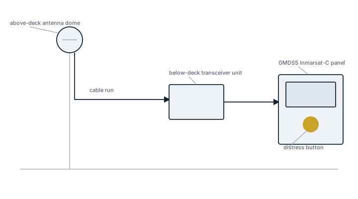
Main components
Above-deck unit
A radome-enclosed antenna, either omnidirectional for Inmarsat-C or a stabilized tracking antenna for FleetBroadband, mounted with clear sky view fore, aft and to both sides.
Below-deck unit
The transceiver and terminal processing unit, connected to the ship's power supply with battery backup, and interfaced to the GMDSS console for distress alerting.
Subscription and network
Service runs through a Land Earth Station and requires an active service subscription; a terminal with lapsed subscription is functionally equipment without a network, whatever its physical condition.
Selection and sizing
The choice between Inmarsat-C (low bandwidth, message-based, mandatory GMDSS function) and FleetBroadband or higher-tier services (broadband voice and data) depends on the vessel's communication needs beyond the regulatory minimum. Redundancy matters for the GMDSS function specifically: many vessels carry the Inmarsat-C terminal as one of two or more independent means of distress alerting required by the vessel's sea area classification.
Regulations and class requirements
SOLAS Chapter IV sets the GMDSS carriage requirements by sea area (A1 through A4), and Inmarsat-C satisfies the requirement for sea areas A1 through A3. Equipment must carry GMDSS type approval, and the interface to the EPIRB and DSC alerting systems is checked during survey. Regular testing of the distress alert function, without actually transmitting a live distress, is part of the vessel's routine drill schedule.
Typical faults
- Radome cracking and water ingress into the above-deck unit, causing corrosion of the antenna electronics that shows up as intermittent signal loss.
- Low-noise amplifier failure in the antenna assembly, degrading receive sensitivity long before it fails completely.
- Firmware or software faults in the terminal unit that require a factory reset or manufacturer intervention to clear.
- Lapsed service subscription, often discovered only when the crew tries to send a message and gets no network response.
- Below-deck unit power supply or battery backup failure, leaving the terminal without power during a mains interruption.
What to look for in a supplier
- Current GMDSS type approval matching the terminal's role in the vessel's radio installation.
- Confirmed Land Earth Station coverage for the trading area the vessel actually operates in.
- An established technical support network able to diagnose faults remotely before committing to a port call for repair.
- Spare above-deck unit components (radome, LNA) that do not require replacing the entire antenna assembly for a minor fault.
Check the subscription status before troubleshooting the hardware; a terminal in perfect working order is silent if the service behind it has lapsed.
6 manufacturers · 16 models
MacGregor
7- Anzeige-/Display-Ausfall durch Elektronik-Alterung
- Sensor-Interface Kommunikationsfehler
- Software-/Firmware-Bugs erfordern Updates
- Antennenkabel-Korrosion durch Deckbelastung
- Spannungsversorgungsprobleme bei Bordnetz-Schwankungen
- Compact, stackable design reduces deck space and simplifies installation on the bridge.
- Integrated antenna eliminates separate mast or pole requirements, lowering overall weight aloft.
- Supports multiple Inmarsat services (FleetBroadband, FleetXpress) for voice, data and e‑navigation applications.
- Designed for direct interface with bridge equipment and AIS, enabling seamless integration into existing navigation suites.
- Modular hardware allows relatively quick replacement of faulty modules during scheduled maintenance.
- Electronic components can age, leading to display or indicator failures if not refreshed regularly.
- Antenna cable is exposed to deck loads; corrosion has been reported when protective measures are insufficient.
- Software/firmware bugs require periodic updates from the manufacturer to maintain compliance and functionality.
- Sensitive to shipboard power fluctuations; voltage instability can cause intermittent outages.
- Sensor‑interface communication errors may arise if wiring or connectors degrade, necessitating quarterly calibration checks.
- Anzeige-/Display-Ausfall durch Elektronik-Alterung
- Sensor-Interface Kommunikationsfehler
- Software-/Firmware-Bugs erfordern Updates
- Antennenkabel-Korrosion durch Deckbelastung
- Spannungsversorgungsprobleme bei Bordnetz-Schwankungen
- Automated antenna stacking reduces manual alignment time and improves pointing accuracy
- Robust marine‑grade housing designed to withstand harsh weather and deck loads
- Integrated remote monitoring and diagnostics via MacGregor’s fleet management platform
- SOLAS‑compliant GMDSS solution with built‑in redundancy for critical communications
- Modular design allows relatively straightforward replacement of faulty modules
- Display units can fail over time due to electronic ageing (known issue)
- Sensor‑interface communication errors may require firmware patches
- Antenna cable corrosion observed when subjected to heavy deck loads
- Power supply sensitivity to shipboard voltage fluctuations can cause outages
- Requires quarterly sensor calibration and monthly backup‑system testing, increasing maintenance workload
- Anzeige-/Display-Ausfall durch Elektronik-Alterung
- Sensor-Interface Kommunikationsfehler
- Software-/Firmware-Bugs erfordern Updates
- Antennenkabel-Korrosion durch Deckbelastung
- Spannungsversorgungsprobleme bei Bordnetz-Schwankungen
- Compact stacked design saves valuable deck space compared with traditional dish antennas
- Built‑in redundancy and automatic alignment improve reliability and reduce downtime
- Supports multiple Inmarsat services (voice, narrowband data, broadband) from a single unit
- Integrated sensor interface simplifies installation and monitoring on the bridge
- SOLAS GMDSS certified, meeting mandatory safety communications requirements
- Installation can require structural reinforcement due to deck load and cable routing
- Display/electronics ageing may lead to occasional screen failures
- Antenna cabling is prone to corrosion if not protected from deck‑load stress
- Firmware/software bugs necessitate regular manufacturer advisories and updates
- Sensitive to voltage fluctuations; requires stable power supply or additional conditioning
- Anzeige-/Display-Ausfall durch Elektronik-Alterung
- Sensor-Interface Kommunikationsfehler
- Software-/Firmware-Bugs erfordern Updates
- Antennenkabel-Korrosion durch Deckbelastung
- Spannungsversorgungsprobleme bei Bordnetz-Schwankungen
- Stackable design allows installation of several antennas in limited deck space
- Integrated power management reduces voltage fluctuation issues on board
- Remote diagnostics and firmware update capability via manufacturer advisory
- SOLAS‑compliant GMDSS functionality with built‑in redundancy
- Proven DNV approval for marine use
- Display units can fail over time due to electronic aging
- Sensor interface communication errors reported in field service bulletins
- Firmware bugs may require frequent updates to maintain stability
- Antenna cable corrosion observed when subjected to deck load and moisture
- Sensitive to severe voltage swings in the ship’s power network
- Anzeige-/Display-Ausfall durch Elektronik-Alterung
- Sensor-Interface Kommunikationsfehler
- Software-/Firmware-Bugs erfordern Updates
- Antennenkabel-Korrosion durch Deckbelastung
- Spannungsversorgungsprobleme bei Bordnetz-Schwankungen
- Compact stackable design saves deck space compared with separate antenna‑modem installations
- DNV‑approved and SOLAS compliant, simplifying certification procedures
- Integrated monitoring allows remote firmware updates and health checks
- Robust housing suited for harsh marine environments
- Standardised mounting reduces installation time
- Higher power draw than some low‑profile alternatives; requires stable shipboard voltage
- Antenna cable is exposed to deck loads and may corrode if not inspected regularly
- Software/firmware updates are required periodically to fix bugs
- Initial cost higher than basic single‑antenna terminals
- Complexity of the stacker can make troubleshooting more time‑consuming
- Anzeige-/Display-Ausfall durch Elektronik-Alterung
- Sensor-Interface Kommunikationsfehler
- Software-/Firmware-Bugs erfordern Updates
- Antennenkabel-Korrosion durch Deckbelastung
- Spannungsversorgungsprobleme bei Bordnetz-Schwankungen
- Compact stackable design saves valuable deck space
- Automated raise/lower mechanism reduces crew workload and improves safety
- Integrated NMEA/RS422 interfaces simplify connection to bridge and monitoring systems
- IMO SOLAS type‑approved and DNV classified for marine use
- Supports both Inmarsat FleetBroadband and Classic services for voice, data and internet
- Mechanical moving parts are subject to wear, corrosion of antenna cables and require regular inspection
- Software/firmware updates are mandatory to resolve known bugs
- Sensitive to shipboard power fluctuations; voltage instability can cause outages
- Higher initial cost compared with fixed‑dish satellite terminals
- Installation requires structural reinforcement for the motorised mast
- Anzeige-/Display-Ausfall durch Elektronik-Alterung
- Sensor-Interface Kommunikationsfehler
- Software-/Firmware-Bugs erfordern Updates
- Antennenkabel-Korrosion durch Deckbelastung
- Spannungsversorgungsprobleme bei Bordnetz-Schwankungen
- Compact, low‑profile design saves deck space and simplifies installation
- Integrated antenna stacker offers auto‑tracking with minimal manual alignment
- Marine‑grade construction meets SOLAS/GMDSS requirements and DNV approval
- Remote monitoring and firmware update capability via manufacturer advisory
- Quick backup‑system test procedures support high availability
- Limited peak bandwidth compared with larger, dedicated VSAT antennas
- Antenna movement mechanisms can be prone to wear in harsh deck environments
- Performance degrades at very high latitudes where Inmarsat coverage is reduced
- Higher upfront cost per unit versus basic handheld satellite phones
- Requires clear sky view; obstructed decks or superstructures may limit placement
Sailor (Cobham)
4
- Antenna pointing issues
- Message queue overflow
- Power supply failure
- Small footprint and lightweight installation – ideal for vessels with limited space
- Low power consumption (≈30 W) suitable for ships with modest electrical capacity
- Full GMDSS compliance, including automatic distress alerting (MAYDAY/URGENT)
- Simple user interface and quick set‑up; integrates easily with existing bridge consoles
- Proven reliability on a wide range of commercial vessels
- Limited data rate of 600 bps restricts bandwidth‑intensive applications
- External antenna must maintain an unobstructed sky view; pointing issues are common in heavy seas
- Message queue can overflow during high traffic periods, leading to delayed transmissions
- No support for newer broadband services (e.g., FleetBroadband or Iridium Certus)
- Power‑supply failures have been reported on older installations
- Antenna stabilization failure
- Radome water ingress
- BDE board failure
- Compact, all‑in‑one unit with built‑in antenna simplifies installation
- Global coverage on Inmarsat L‑band network ensures reliable voice and email service
- Low power consumption suitable for vessels with limited electrical capacity
- Integrated remote management via FleetBroadband services enables diagnostics from shore
- Proven track record on a wide range of commercial and offshore vessels
- Limited bandwidth (432 kbps) compared with newer terminals such as FleetBroadband‑2 or Iridium Certus
- Reported antenna stabilization failures can affect link quality in heavy seas
- Radome water ingress has been observed if gasket maintenance is neglected
- BDE (Baseband/Digital Electronics) board failures may require costly field repairs
- Higher subscription cost per megabyte than some competing low‑rate services
- Radome seal aging
- Lower gain in rough seas
- Power supply heat issues
- Small radome (≈0.5 m) fits on vessels with limited deck space
- Integrated voice and data (up to 284 kbps) over the Inmarsat FleetBroadband network
- Quick installation and alignment; no mechanical tracking required
- Lower acquisition cost compared with larger FleetBroadband antennas
- Limited bandwidth; not ideal for high‑volume data applications
- Performance degrades in heavy sea states due to lower gain
- Radome seal can age, leading to potential water ingress
- Power supply may generate heat and require additional ventilation
- Limited bandwidth for modern needs
- Antenna tracking loss
- Obsolescence risk
- Proven reliability with many years of service in the field
- Compact size and low power consumption suitable for small‑to‑medium vessels
- Integrated voice and data on a single unit, meeting GMDSS requirements
- Global Inmarsat coverage (except polar regions)
- Simple installation and straightforward operation
- Maximum data rate of only 150 kbps limits modern crew‑welfare and IoT applications
- Antenna tracking can be lost in high sea states or if not properly aligned
- Older hardware approaching obsolescence; limited support for newer services (Fleet One, VSAT)
- No built‑in redundancy; a single point of failure for both voice and data
- Limited scalability – upgrading bandwidth requires full equipment replacement
Intellian
2
- Pedestal motor failure
- Radome UV degradation
- ACU firmware issues
- Small footprint – fits on vessels where space is limited
- Integrated antenna and modem simplifies installation and commissioning
- Supports Inmarsat GX service with high‑speed broadband (up to ~30 Mbps downstream)
- Designed for vessels up to 100 m, covering a wide range of small‑to‑mid size ships
- Lower power consumption compared with larger gyro‑stabilised antennas
- Limited antenna gain relative to larger gyro‑stabilised GX terminals – lower performance in marginal weather
- Reported pedestal motor failures can cause downtime if not proactively maintained
- Radome UV degradation over time may require periodic replacement
- ACU firmware issues have been noted, necessitating regular software updates
- Bandwidth caps are tighter than on larger GX systems, which may limit data‑intensive operations
- Higher weight/wind load
- Pedestal bearing wear
- BUC failure
- High data rates (up to ~50 Mbps) on the Inmarsat GX network
- Large aperture improves link margin in heavy seas and adverse weather
- Dual‑polarisation and full‑motion stabilization maintain connectivity during vessel maneuvers
- Future‑proof Ka‑band platform supports voice, broadband and IoT services
- Significant weight and wind load require reinforced mounting structures
- Pedestal bearing wear reported in long‑term service
- Integrated BUC can be a reliability weak point
- Higher power consumption and installation cost compared with smaller L‑band terminals
Addvalue
1
- Small antenna gain limits
- Voice quality
- Firmware stability
- Low purchase and subscription cost – budget option for fishing and workboats
- Compact, integrated antenna reduces installation effort
- Supports both voice (VoIP) and low‑rate data services on a single platform
- Web‑based remote monitoring and configuration tools
- Designed for vessels under 30 m with limited deck space
- Small antenna gain limits performance in rough sea states or high latitudes
- Voice quality can be degraded, especially during heavy traffic or bad weather
- Reported firmware stability issues requiring periodic updates
- Data rate capped at ~100 kbps – insufficient for bandwidth‑intensive applications
- Limited to Inmarsat Fleet One service; no higher‑speed options
Inmarsat
1
- Ka-Band rain fade
- Antenna size and weight
- High airtime costs
- Up to 50 Mbps downlink enables crew welfare and real‑time e‑navigation services
- Dual‑antenna architecture provides automatic L‑band redundancy if Ka‑band is degraded
- Global coverage (except high latitudes) meets IMO GMDSS Class A requirements
- Low latency (~150 ms) suitable for video conferencing and remote monitoring
- Ka‑band performance can be reduced by heavy rain (rain fade)
- Antenna size and mounting weight are larger than typical L‑band terminals
- Higher capital cost and airtime rates compared with lower‑throughput solutions
- Limited coverage near the polar regions
JRC
1- Antenna stabilization
- BDE unit failure
- Radome seal aging
- Integrated GMDSS capability meets mandatory distress signalling requirements without extra hardware
- Compact footprint and low power draw suit medium‑size vessels and offshore platforms
- Automatic antenna stabilization maintains link quality in heavy seas
- Proven reliability with a long service history on commercial fleets
- Straightforward integration with JRC bridge consoles and existing ship IT networks
- Maximum data rate limited to 432 kbps, insufficient for bandwidth‑intensive applications
- Historical issues reported with antenna stabilisation mechanisms and radome seal ageing
- BDE (Baseband Data Equipment) unit failures have been observed in older installations
- Higher acquisition cost compared with newer low‑cost L‑band terminals offering similar speeds
- Limited upgrade path to higher‑speed FleetBroadband services without hardware replacement