OceanSphere
Engines

AIS Transponder (Class A)

medium 39 models total

A Class A AIS transponder automatically broadcasts a ship's identity, position, course and speed to other vessels and shore stations every few seconds while under way, and receives the same data back, functioning as mandatory collision-avoidance equipment rather than an optional aid.

Read more — AIS Transponder (Class A) explained

What Makes a Class A AIS Transponder Different

A Class A AIS transponder transmits automatically and continuously, position, course, speed, heading, rate of turn and voyage data, using dedicated VHF channels, without needing anyone to key a call. Reporting intervals shorten automatically as speed or manoeuvring status changes, from as long as three minutes at anchor down to about two seconds when a ship is turning at speed. That automatic, high-frequency, mandatory-carriage behaviour is what separates Class A from Class B, the lower-power, lower-priority transponder fitted to smaller commercial and leisure craft, which transmits less often and yields channel access to Class A traffic. Class A is the SOLAS-mandated type; Class B is never an acceptable substitute for a vessel required to carry AIS.
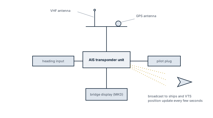
Class A AIS transponder arrangement
Block arrangement of a Class A AIS transponder showing its VHF and GPS antennas, the bridge display, the pilot plug and heading input, and the radio broadcast to other ships and VTS.

Main Components

VHF transceiver

Transmits and receives on the two internationally designated AIS VHF channels, switching automatically between them and monitoring for regional channel changes broadcast by shore authorities.

GNSS receiver

An internal or externally fed GPS/GNSS position source providing the position, course and speed data transmitted in each report; accuracy here directly affects the reliability of every ship relying on that data for collision avoidance.

Minimum keyboard and display (MKD)

The bridge unit used to enter voyage-related data, destination, ETA, cargo category, number of persons on board, and to view received traffic; many ships instead interface AIS data into the ECDIS or radar and use the MKD only as backup.

Pilot plug

A standardized connector giving a pilot's portable navigation unit direct access to the ship's AIS and other sensor data on boarding.

Sensor interfaces

Inputs from the gyrocompass, rate-of-turn indicator and speed log feed additional fields into the AIS broadcast beyond what GNSS alone provides.

Selection and Sizing

  • Type approval matching the flag state's accepted equipment list, since AIS is SOLAS-mandated and not a discretionary fit-out choice
  • Integration options with the ship's ECDIS, radar and VDR, since AIS data is now expected to overlay directly on the primary navigation displays
  • Pilot plug provision and location, positioned for practical access when a pilot boards
  • Long-range AIS capability where trading patterns or company policy call for satellite-relayed position reporting beyond VHF range

Regulations and Class

SOLAS Chapter V requires AIS Class A carriage on all ships of 300 gross tonnage and above engaged on international voyages, cargo ships of 500 gross tonnage and above not engaged on international voyages, and all passenger ships regardless of size. The transponder must remain in operation at all times except where its operation might compromise the safety or security of the ship, a decision the master documents in the log. Static data such as ship name, call sign, IMO number and dimensions, and voyage data such as destination, ETA and draught, must be kept current, since inaccurate AIS data undermines the collision-avoidance purpose of the whole system for every vessel receiving it.

Typical Faults

FaultCauseConsequence
Incorrect or stale voyage dataDestination, ETA or draught not updated after departure or cargo changeOther vessels and VTS act on wrong information, undermines traffic management
Position jumps or freezes on other ships' displaysGNSS signal loss or degraded antenna receptionLoss of reliable collision-avoidance data at the worst possible time
Transponder switched off without justificationCrew silencing AIS believing it aids security or avoids attentionSOLAS non-compliance, Port State Control deficiency, real collision risk to other traffic
Static data errors such as wrong MMSI, ship type or dimensionsIncorrect programming at installation, never corrected afterwardPersistent identification confusion across every vessel and VTS that receives the signal

What to Look for in a Supplier

  • Current type approval matching the flag state's accepted list and the applicable IMO performance standard
  • Straightforward integration with the ship's existing ECDIS, radar and VDR rather than a standalone display nobody actually uses
  • GNSS antenna placement guidance suited to the vessel's superstructure, since shadowing degrades position quality
  • Support for correcting static and voyage data quickly, since errors here are a compliance issue as much as a technical one

Check static and voyage data every time cargo, destination or draught changes; an AIS transponder broadcasting confidently wrong information is arguably worse than one that is silent, because everyone else trusts it.

23 manufacturers · 39 models

Furuno

5
FA-170 AIS Transponder unverified
Class type
A
IMO Compliant
ja
Channels
2
Display
ja
Common Failures & Inspection Points
  • GNSS, heading or speed-input failure causes invalid dynamic data and sensor alarms
  • VHF antenna or feeder faults reduce transmit and receive range and may trigger built-in-test warnings
  • Incorrect static or voyage data results in wrong vessel information being transmitted
  • Power-supply or network faults cause unit resets, blank displays or loss of target data to bridge systems
  • Internal transceiver or timing faults cause transmission alarms or missing nearby targets
Service: Verify own-ship static and voyage data, sensor inputs, antenna condition, alarms and target reception. Compare transmitted information with approved vessel particulars. Check interfaces to ECDIS, radar and pilot connections where fitted. Refer to the manufacturer documentation for the exact figure for radio-performance and service criteria.
Spare Parts: Carry fuses, power-supply parts, antenna connectors, interface cables and manufacturer-supported display or control modules where justified.
Use Cases: Traffic awareness, collision-avoidance support and regulatory vessel identification.
FA-150 AIS Transponder unverified
Class type
A
IMO Compliant
ja
Channels
2
Display
ja
Common Failures & Inspection Points
  • GNSS, heading or speed-input failure causes invalid dynamic data and sensor alarms
  • VHF antenna or feeder faults reduce transmit and receive range and may trigger built-in-test warnings
  • Incorrect static or voyage data results in wrong vessel information being transmitted
  • Power-supply or network faults cause unit resets, blank displays or loss of target data to bridge systems
  • Internal transceiver or timing faults cause transmission alarms or missing nearby targets
Service: Verify own-ship static and voyage data, sensor inputs, antenna condition, alarms and target reception. Compare transmitted information with approved vessel particulars. Check interfaces to ECDIS, radar and pilot connections where fitted. Refer to the manufacturer documentation for the exact figure for radio-performance and service criteria.
Spare Parts: Carry fuses, power-supply parts, antenna connectors, interface cables and manufacturer-supported display or control modules where justified.
Use Cases: Traffic awareness, collision-avoidance support and regulatory vessel identification.
FA-1710 AIS Transponder unverified
Class type
A
IMO Compliant
ja
Channels
2
Display
ja
Color display
ja
Common Failures & Inspection Points
  • GNSS, heading or speed-input failure causes invalid dynamic data and sensor alarms
  • VHF antenna or feeder faults reduce transmit and receive range and may trigger built-in-test warnings
  • Incorrect static or voyage data results in wrong vessel information being transmitted
  • Power-supply or network faults cause unit resets, blank displays or loss of target data to bridge systems
  • Internal transceiver or timing faults cause transmission alarms or missing nearby targets
Service: Verify own-ship static and voyage data, sensor inputs, antenna condition, alarms and target reception. Compare transmitted information with approved vessel particulars. Check interfaces to ECDIS, radar and pilot connections where fitted. Refer to the manufacturer documentation for the exact figure for radio-performance and service criteria.
Spare Parts: Carry fuses, power-supply parts, antenna connectors, interface cables and manufacturer-supported display or control modules where justified.
Use Cases: Traffic awareness, collision-avoidance support and regulatory vessel identification.
FA-170 with 7in Display unverified
Class type
B
IMO Compliant
nein
Common Failures & Inspection Points
  • GNSS, heading or speed-input failure causes invalid dynamic data and sensor alarms
  • VHF antenna or feeder faults reduce transmit and receive range and may trigger built-in-test warnings
  • Incorrect static or voyage data results in wrong vessel information being transmitted
  • Power-supply or network faults cause unit resets, blank displays or loss of target data to bridge systems
  • Internal transceiver or timing faults cause transmission alarms or missing nearby targets
Service: Verify own-ship static and voyage data, sensor inputs, antenna condition, alarms and target reception. Compare transmitted information with approved vessel particulars. Check interfaces to ECDIS, radar and pilot connections where fitted. Refer to the manufacturer documentation for the exact figure for radio-performance and service criteria.
Spare Parts: Carry fuses, power-supply parts, antenna connectors, interface cables and manufacturer-supported display or control modules where justified.
Use Cases: Traffic awareness, collision-avoidance support and regulatory vessel identification.
FELCOM-19 LRIT unverified
Type
LRIT
IMO Compliant
ja
Inmarsat (°C)
ja
Common Failures & Inspection Points
  • Antenna, feeder or casing damage reduces communication or locating performance and may cause self-test faults
  • Battery, emergency-power or power-supply deterioration causes resets, low-voltage alarms or failure to operate
  • Water ingress or corrosion causes intermittent operation, damaged connectors or internal faults
  • Configuration, registration or identity errors cause incorrect vessel or beacon information
  • Internal transceiver, display or control faults cause failed self-tests, missing communications or unavailable emergency functions
Service: Inspect antennas, casing, mounting, power supplies, emergency batteries, controls and programmed identity data as applicable. Perform only approved self-tests and permitted radio tests. Verify accessibility, release arrangements and emergency-power availability where required. Refer to manufacturer and regulatory documentation for the exact figure for test and replacement criteria.
Spare Parts: Carry fuses, handsets or microphones where applicable, approved batteries or chargers, antenna connectors, mounting or release parts and supported control modules.
Use Cases: Distress, safety, ship-to-ship, ship-to-shore and search-and-rescue service.

JRC

4
JCY-1800 AIS Transponder unverified
Class type
A
IMO Compliant
ja
Channels
2
Common Failures & Inspection Points
  • GNSS, heading or speed-input failure causes invalid dynamic data and sensor alarms
  • VHF antenna or feeder faults reduce transmit and receive range and may trigger built-in-test warnings
  • Incorrect static or voyage data results in wrong vessel information being transmitted
  • Power-supply or network faults cause unit resets, blank displays or loss of target data to bridge systems
  • Internal transceiver or timing faults cause transmission alarms or missing nearby targets
Service: Verify own-ship static and voyage data, sensor inputs, antenna condition, alarms and target reception. Compare transmitted information with approved vessel particulars. Check interfaces to ECDIS, radar and pilot connections where fitted. Refer to the manufacturer documentation for the exact figure for radio-performance and service criteria.
Spare Parts: Carry fuses, power-supply parts, antenna connectors, interface cables and manufacturer-supported display or control modules where justified.
Use Cases: Traffic awareness, collision-avoidance support and regulatory vessel identification.
JCY-1900 AIS Transponder unverified
Class type
A
IMO Compliant
ja
Channels
2
Color display
ja
Common Failures & Inspection Points
  • GNSS, heading or speed-input failure causes invalid dynamic data and sensor alarms
  • VHF antenna or feeder faults reduce transmit and receive range and may trigger built-in-test warnings
  • Incorrect static or voyage data results in wrong vessel information being transmitted
  • Power-supply or network faults cause unit resets, blank displays or loss of target data to bridge systems
  • Internal transceiver or timing faults cause transmission alarms or missing nearby targets
Service: Verify own-ship static and voyage data, sensor inputs, antenna condition, alarms and target reception. Compare transmitted information with approved vessel particulars. Check interfaces to ECDIS, radar and pilot connections where fitted. Refer to the manufacturer documentation for the exact figure for radio-performance and service criteria.
Spare Parts: Carry fuses, power-supply parts, antenna connectors, interface cables and manufacturer-supported display or control modules where justified.
Use Cases: Traffic awareness, collision-avoidance support and regulatory vessel identification.
JCY-1800 with Keyboard unverified
Class type
B
IMO Compliant
nein
Common Failures & Inspection Points
  • Sensor, antenna or transducer fault, typically indicated by missing, unstable or implausible navigation data
  • Power-supply or processor failure, typically indicated by blank display, rebooting or unavailable function
  • Network/interface fault, typically indicated by missing data on connected bridge systems or communication alarms
  • Cable/connector corrosion or water ingress, typically indicated by intermittent operation or signal loss
  • Recording/storage or software fault on recorder-type equipment, typically indicated by data gaps, recording alarms or failed playback
Service: Check self-tests, sensor/transducer condition, data interfaces, time/position inputs, recording status where applicable, power supplies and alarm history; performance tests and calibration must follow approved manufacturer and statutory procedures.
Spare Parts: Carry critical fuses, power supplies, interface modules, storage media where approved, sensors/transducers or display peripherals according to equipment criticality.
Use Cases: Used on merchant, passenger, offshore and naval vessels for navigation, bridge situational awareness, environmental sensing and voyage-data recording. This entry applies specifically to the AIS Transponder (Class A) variant identified as JRC JCY-1800 with Keyboard.
JUE-95 LRIT unverified
Type
LRIT
IMO Compliant
ja
Inmarsat (°C)
ja
Common Failures & Inspection Points
  • Loss of supply power from a tripped breaker, failed power unit, loose connection, or depleted reserve battery causes a dead unit, rebooting, or failure to transmit
  • Antenna, feeder, connector, or matching fault caused by corrosion, water ingress, or physical damage results in poor range, failed transmission, or weak received signals
  • Control-panel, display, keypad, or software faults can prevent channel selection, message handling, or normal operator input
  • Interface or position-data failure caused by wiring, configuration, or sensor faults can remove position information or connected-system data
  • Internal transmitter, receiver, or modem faults caused by component ageing or overheating can produce intermittent communication, alarms, or inability to establish a link
Service: Verify primary and reserve power, antenna and feeder condition, distress and safety functions permitted for routine testing, interfaces, audio quality, time and position inputs, and logged self-test results. Any regulatory test or adjustment must follow the vessel's radio procedures and manufacturer documentation.
Spare Parts: Carry the model-specific fuses, approved power-supply items, handset or microphone accessories, connector and sealing items, and critical interface or antenna components recommended by the manufacturer and vessel radio-maintenance plan.
Use Cases: Used on SOLAS merchant ships, offshore vessels, passenger ships, fishing vessels, workboats, and other craft requiring marine radio, distress, safety, or navigation communications.

Kongsberg Maritime

3
Seatex AIS 200 unverified
Class type
A
IMO Compliant
ja
Channels
2
Common Failures & Inspection Points
  • Loss of primary or reserve power from a tripped breaker, failed power unit, loose connection, or depleted battery causes a dead unit, rebooting, or failed transmission
  • Antenna, feeder, connector, or matching faults from corrosion, water ingress, or physical damage cause poor range or weak received signals
  • Control-panel, display, keypad, or software faults prevent channel selection, message handling, or operator input
  • Interface or position-data failure from wiring, configuration, or sensor faults removes position or connected-system data
  • Internal transmitter, receiver, or modem faults from component ageing or overheating cause intermittent communication, alarms, or inability to establish a link
Service: Verify primary and reserve power, antenna and feeder condition, permitted distress/safety self-tests, interfaces, audio quality, time and position inputs, and logged faults. Regulatory tests and adjustments must follow vessel radio procedures and manufacturer documentation.
Spare Parts: Carry model-specific fuses, approved power-supply items, handset or microphone accessories where relevant, connector and sealing items, and critical interface or antenna components recommended by the manufacturer.
Use Cases: Used on SOLAS merchant ships, offshore vessels, passenger ships, fishing vessels, workboats, and other craft requiring marine radio, distress, safety, or navigation communications.
Seatex AIS 300 Dual Channel unverified
Class type
B
IMO Compliant
nein
Common Failures & Inspection Points
  • Sensor, antenna or transducer fault caused by damage, fouling, water ingress or electronics failure, resulting in missing, unstable or implausible navigation data
  • Power-supply failure caused by breaker, converter or wiring faults, resulting in loss of indication or repeated restarts
  • Network or interface failure caused by damaged cabling, port faults or configuration changes, resulting in loss of data to connected bridge systems
  • Display, processor or control failure caused by hardware or software faults, resulting in frozen, blank or unavailable functions
  • Calibration, alignment or configuration error caused by incorrect setup or maintenance, resulting in persistent disagreement with independent references
Service: Compare indicated data and system response with independent references and investigate persistent disagreement. Inspect sensors, antennas, cabling, power supplies, displays and network interfaces applicable to the installation. Verify required alarms and outputs to connected bridge systems using approved procedures. Back up configuration before authorized software or hardware changes. Protect exposed sensors and antennas from paint, deposits and water ingress. Refer to the manufacturer documentation for the exact figure for test, calibration, alignment and recovery procedures.
Spare Parts: Keep fuses, selected power-supply and interface modules, cables or connectors and manufacturer-recommended sensor or electronic spares. Replacement core units must remain compatible with the approved bridge installation. Preserve calibration, identity and configuration data.
Use Cases: It is used for bridge navigation and monitoring on merchant ships, passenger vessels, offshore units or other vessel types where this equipment category is fitted.
Seatex AIS Inland unverified
IMO Compliant
ja
Common Failures & Inspection Points
  • Sensor, antenna or transducer fault, typically indicated by missing, unstable or implausible navigation data
  • Power-supply or processor failure, typically indicated by blank display, rebooting or unavailable function
  • Network/interface fault, typically indicated by missing data on connected bridge systems or communication alarms
  • Cable/connector corrosion or water ingress, typically indicated by intermittent operation or signal loss
  • Recording/storage or software fault on recorder-type equipment, typically indicated by data gaps, recording alarms or failed playback
Service: Check self-tests, sensor/transducer condition, data interfaces, time/position inputs, recording status where applicable, power supplies and alarm history; performance tests and calibration must follow approved manufacturer and statutory procedures.
Spare Parts: Carry critical fuses, power supplies, interface modules, storage media where approved, sensors/transducers or display peripherals according to equipment criticality.
Use Cases: Used on merchant, passenger, offshore and naval vessels for navigation, bridge situational awareness, environmental sensing and voyage-data recording. This entry applies specifically to the AIS Transponder (Class A) variant identified as Kongsberg Seatex AIS Inland.

Sailor

3
Sailor 6280 AIS unverified
Class type
A
IMO Compliant
ja
Channels
2
Common Failures & Inspection Points
  • Loss of primary or reserve power from a tripped breaker, failed power unit, loose connection, or depleted battery causes a dead unit, rebooting, or failed transmission
  • Antenna, feeder, connector, or matching faults from corrosion, water ingress, or physical damage cause poor range or weak received signals
  • Control-panel, display, keypad, or software faults prevent channel selection, message handling, or operator input
  • Interface or position-data failure from wiring, configuration, or sensor faults removes position or connected-system data
  • Internal transmitter, receiver, or modem faults from component ageing or overheating cause intermittent communication, alarms, or inability to establish a link
Service: Verify primary and reserve power, antenna and feeder condition, permitted distress/safety self-tests, interfaces, audio quality, time and position inputs, and logged faults. Regulatory tests and adjustments must follow vessel radio procedures and manufacturer documentation.
Spare Parts: Carry model-specific fuses, approved power-supply items, handset or microphone accessories where relevant, connector and sealing items, and critical interface or antenna components recommended by the manufacturer.
Use Cases: Used on SOLAS merchant ships, offshore vessels, passenger ships, fishing vessels, workboats, and other craft requiring marine radio, distress, safety, or navigation communications.
Sailor 6280 AIS GMDSS unverified
Class type
A
IMO Compliant
ja
Gmdss integrated
ja
Common Failures & Inspection Points
  • Loss of supply power from a tripped breaker, failed power unit, loose connection, or depleted reserve battery causes a dead unit, rebooting, or failure to transmit
  • Antenna, feeder, connector, or matching fault caused by corrosion, water ingress, or physical damage results in poor range, failed transmission, or weak received signals
  • Control-panel, display, keypad, or software faults can prevent channel selection, message handling, or normal operator input
  • Interface or position-data failure caused by wiring, configuration, or sensor faults can remove position information or connected-system data
  • Internal transmitter, receiver, or modem faults caused by component ageing or overheating can produce intermittent communication, alarms, or inability to establish a link
Service: Verify primary and reserve power, antenna and feeder condition, distress and safety functions permitted for routine testing, interfaces, audio quality, time and position inputs, and logged self-test results. Any regulatory test or adjustment must follow the vessel's radio procedures and manufacturer documentation.
Spare Parts: Carry the model-specific fuses, approved power-supply items, handset or microphone accessories, connector and sealing items, and critical interface or antenna components recommended by the manufacturer and vessel radio-maintenance plan.
Use Cases: Used on SOLAS merchant ships, offshore vessels, passenger ships, fishing vessels, workboats, and other craft requiring marine radio, distress, safety, or navigation communications.
Sailor 6150 LRIT unverified
Type
LRIT
IMO Compliant
ja
Inmarsat (°C)
ja
Common Failures & Inspection Points
  • Loss of primary or reserve power from a tripped breaker, failed power unit, loose connection, or depleted battery causes a dead unit, rebooting, or failed transmission
  • Antenna, feeder, connector, or matching faults from corrosion, water ingress, or physical damage cause poor range or weak received signals
  • Control-panel, display, keypad, or software faults prevent channel selection, message handling, or operator input
  • Interface or position-data failure from wiring, configuration, or sensor faults removes position or connected-system data
  • Internal transmitter, receiver, or modem faults from component ageing or overheating cause intermittent communication, alarms, or inability to establish a link
Service: Verify primary and reserve power, antenna and feeder condition, permitted distress/safety self-tests, interfaces, audio quality, time and position inputs, and logged faults. Regulatory tests and adjustments must follow vessel radio procedures and manufacturer documentation.
Spare Parts: Carry model-specific fuses, approved power-supply items, handset or microphone accessories where relevant, connector and sealing items, and critical interface or antenna components recommended by the manufacturer.
Use Cases: Used on SOLAS merchant ships, offshore vessels, passenger ships, fishing vessels, workboats, and other craft requiring marine radio, distress, safety, or navigation communications.

Digital Yacht

2
AIT5000 Class B+ unverified
Class type
B
IMO Compliant
nein
Common Failures & Inspection Points
  • GNSS, heading or speed-input failure causes invalid dynamic data and sensor alarms
  • VHF antenna or feeder faults reduce transmit and receive range and may trigger built-in-test warnings
  • Incorrect static or voyage data results in wrong vessel information being transmitted
  • Power-supply or network faults cause unit resets, blank displays or loss of target data to bridge systems
  • Internal transceiver or timing faults cause transmission alarms or missing nearby targets
Service: Verify own-ship static and voyage data, sensor inputs, antenna condition, alarms and target reception. Compare transmitted information with approved vessel particulars. Check interfaces to ECDIS, radar and pilot connections where fitted. Refer to the manufacturer documentation for the exact figure for radio-performance and service criteria.
Spare Parts: Carry fuses, power-supply parts, antenna connectors, interface cables and manufacturer-supported display or control modules where justified.
Use Cases: Traffic awareness, collision-avoidance support and regulatory vessel identification.
iAISTX Class B unverified
Class type
B
IMO Compliant
nein
Common Failures & Inspection Points
  • GNSS, heading or speed-input failure causes invalid dynamic data and sensor alarms
  • VHF antenna or feeder faults reduce transmit and receive range and may trigger built-in-test warnings
  • Incorrect static or voyage data results in wrong vessel information being transmitted
  • Power-supply or network faults cause unit resets, blank displays or loss of target data to bridge systems
  • Internal transceiver or timing faults cause transmission alarms or missing nearby targets
Service: Verify own-ship static and voyage data, sensor inputs, antenna condition, alarms and target reception. Compare transmitted information with approved vessel particulars. Check interfaces to ECDIS, radar and pilot connections where fitted. Refer to the manufacturer documentation for the exact figure for radio-performance and service criteria.
Spare Parts: Carry fuses, power-supply parts, antenna connectors, interface cables and manufacturer-supported display or control modules where justified.
Use Cases: Traffic awareness, collision-avoidance support and regulatory vessel identification.

em-trak

2
B954 Class B+ unverified
Class type
B
IMO Compliant
nein
Common Failures & Inspection Points
  • Antenna, feeder or casing damage reduces communication or locating performance and may cause self-test faults
  • Battery, emergency-power or power-supply deterioration causes resets, low-voltage alarms or failure to operate
  • Water ingress or corrosion causes intermittent operation, damaged connectors or internal faults
  • Configuration, registration or identity errors cause incorrect vessel or beacon information
  • Internal transceiver, display or control faults cause failed self-tests, missing communications or unavailable emergency functions
Service: Inspect antennas, casing, mounting, power supplies, emergency batteries, controls and programmed identity data as applicable. Perform only approved self-tests and permitted radio tests. Verify accessibility, release arrangements and emergency-power availability where required. Refer to manufacturer and regulatory documentation for the exact figure for test and replacement criteria.
Spare Parts: Carry fuses, handsets or microphones where applicable, approved batteries or chargers, antenna connectors, mounting or release parts and supported control modules.
Use Cases: Distress, safety, ship-to-ship, ship-to-shore and search-and-rescue service.
A100 Inland AIS unverified
IMO Compliant
ja
Common Failures & Inspection Points
  • Loss of primary or reserve power from a tripped breaker, failed power unit, loose connection, or depleted battery causes a dead unit, rebooting, or failed transmission
  • Antenna, feeder, connector, or matching faults from corrosion, water ingress, or physical damage cause poor range or weak received signals
  • Control-panel, display, keypad, or software faults prevent channel selection, message handling, or operator input
  • Interface or position-data failure from wiring, configuration, or sensor faults removes position or connected-system data
  • Internal transmitter, receiver, or modem faults from component ageing or overheating cause intermittent communication, alarms, or inability to establish a link
Service: Verify primary and reserve power, antenna and feeder condition, permitted distress/safety self-tests, interfaces, audio quality, time and position inputs, and logged faults. Regulatory tests and adjustments must follow vessel radio procedures and manufacturer documentation.
Spare Parts: Carry model-specific fuses, approved power-supply items, handset or microphone accessories where relevant, connector and sealing items, and critical interface or antenna components recommended by the manufacturer.
Use Cases: Used on SOLAS merchant ships, offshore vessels, passenger ships, fishing vessels, workboats, and other craft requiring marine radio, distress, safety, or navigation communications.

SAAB

2
R5 Supreme Inland AIS unverified
Class type
A
IMO Compliant
nein
Common Failures & Inspection Points
  • Sensor, antenna or transducer fault, typically indicated by missing, unstable or implausible navigation data
  • Power-supply or processor failure, typically indicated by blank display, rebooting or unavailable function
  • Network/interface fault, typically indicated by missing data on connected bridge systems or communication alarms
  • Cable/connector corrosion or water ingress, typically indicated by intermittent operation or signal loss
  • Recording/storage or software fault on recorder-type equipment, typically indicated by data gaps, recording alarms or failed playback
Service: Check self-tests, sensor/transducer condition, data interfaces, time/position inputs, recording status where applicable, power supplies and alarm history; performance tests and calibration must follow approved manufacturer and statutory procedures.
Spare Parts: Carry critical fuses, power supplies, interface modules, storage media where approved, sensors/transducers or display peripherals according to equipment criticality.
Use Cases: Used on merchant, passenger, offshore and naval vessels for navigation, bridge situational awareness, environmental sensing and voyage-data recording. This entry applies specifically to the AIS Transponder (Class A) variant identified as Saab R5 Supreme Inland AIS.
R5 Inland AIS unverified
IMO Compliant
ja
Common Failures & Inspection Points
  • Sensor or antenna degradation caused by contamination, damage, ageing or poor exposure can produce missing, unstable or implausible data
  • Connector, cable or network faults caused by vibration, corrosion or disturbed terminations can cause intermittent data loss or interface alarms
  • Power-supply or internal electronics failure caused by ageing, heat or poor ventilation can result in resets, blank indications or complete loss of function
  • Configuration or software errors after service or replacement can cause incorrect data, rejected inputs or loss of communication with other bridge equipment
  • Mechanical damage or water ingress at exposed components can lead to erratic readings, repeated alarms or loss of the affected channel
Service: Inspect exposed sensors or antennas, cable routes, connectors, power supplies, displays and network interfaces. Confirm that indicated or recorded data is plausible and that built-in tests and alarms operate. Compare configuration and test results with the vessel's approved records and manufacturer documentation.
Spare Parts: Keep maker-recommended fuses, connectors, sensor accessories, fans, interface or power modules and other approved line-replaceable items that match the installed configuration.
Use Cases: Commercial ships, passenger vessels, offshore vessels and workboats requiring bridge navigation, recording, environmental or traffic information.

Transas Marine

2
LRIT Transceiver unverified
Type
LRIT
IMO Compliant
ja
Inmarsat (°C)
ja
Common Failures & Inspection Points
  • Loss of primary or reserve power from a tripped breaker, failed power unit, loose connection, or depleted battery causes a dead unit, rebooting, or failed transmission
  • Antenna, feeder, connector, or matching faults from corrosion, water ingress, or physical damage cause poor range or weak received signals
  • Control-panel, display, keypad, or software faults prevent channel selection, message handling, or operator input
  • Interface or position-data failure from wiring, configuration, or sensor faults removes position or connected-system data
  • Internal transmitter, receiver, or modem faults from component ageing or overheating cause intermittent communication, alarms, or inability to establish a link
Service: Verify primary and reserve power, antenna and feeder condition, permitted distress/safety self-tests, interfaces, audio quality, time and position inputs, and logged faults. Regulatory tests and adjustments must follow vessel radio procedures and manufacturer documentation.
Spare Parts: Carry model-specific fuses, approved power-supply items, handset or microphone accessories where relevant, connector and sealing items, and critical interface or antenna components recommended by the manufacturer.
Use Cases: Used on SOLAS merchant ships, offshore vessels, passenger ships, fishing vessels, workboats, and other craft requiring marine radio, distress, safety, or navigation communications.
T-100 AIS AtoN unverified
IMO Compliant
ja
Common Failures & Inspection Points
  • Loss of primary or reserve power from a tripped breaker, failed power unit, loose connection, or depleted battery causes a dead unit, rebooting, or failed transmission
  • Antenna, feeder, connector, or matching faults from corrosion, water ingress, or physical damage cause poor range or weak received signals
  • Control-panel, display, keypad, or software faults prevent channel selection, message handling, or operator input
  • Interface or position-data failure from wiring, configuration, or sensor faults removes position or connected-system data
  • Internal transmitter, receiver, or modem faults from component ageing or overheating cause intermittent communication, alarms, or inability to establish a link
Service: Verify primary and reserve power, antenna and feeder condition, permitted distress/safety self-tests, interfaces, audio quality, time and position inputs, and logged faults. Regulatory tests and adjustments must follow vessel radio procedures and manufacturer documentation.
Spare Parts: Carry model-specific fuses, approved power-supply items, handset or microphone accessories where relevant, connector and sealing items, and critical interface or antenna components recommended by the manufacturer.
Use Cases: Used on SOLAS merchant ships, offshore vessels, passenger ships, fishing vessels, workboats, and other craft requiring marine radio, distress, safety, or navigation communications.

Vesper Marine

2
Cortex V1 AIS+VHF unverified
Class type
A
IMO Compliant
nein
Common Failures & Inspection Points
  • GNSS, VHF antenna or transceiver fault caused by damage, poor connections or electronics failure, resulting in missing targets, transmission alarms or invalid own-ship data
  • Power-supply failure caused by breaker, converter or wiring faults, resulting in loss of the equipment or repeated restarts
  • Network or interface failure caused by damaged cabling, port faults or configuration changes, resulting in loss of data to connected systems
  • Display, processor or control failure caused by hardware or software faults, resulting in frozen indications, alarms or unavailable functions
  • Incorrect configuration or time, position or sensor input caused by setup or upstream faults, resulting in misleading or incomplete information
Service: Inspect sensors, antennas, transducers, cameras, cabling, power supplies and network interfaces applicable to the installed equipment. Compare displayed information with independent references where possible and investigate recurring alarms or missing channels. Verify required outputs to other bridge systems and preserve configuration before approved software or hardware maintenance. Clean exposed sensors and optical surfaces without damaging coatings or seals. Check backup power or recording arrangements where applicable. Refer to the manufacturer documentation for the exact figure for test, calibration, update and recovery procedures.
Spare Parts: Keep fuses, selected power-supply and interface modules, cables or connectors, storage media where applicable and manufacturer-recommended sensor or electronic spares. Replacement core units must remain compatible with the approved bridge installation. Preserve configuration and recorded setup data.
Use Cases: Bridge navigation, monitoring, recording and maritime safety information functions on merchant ships, passenger vessels, offshore units and workboats.
Cortex M1 AIS Monitor unverified
Class type
A
IMO Compliant
nein
Common Failures & Inspection Points
  • Sensor, antenna or transducer fault caused by damage, fouling, water ingress or electronics failure, resulting in missing, unstable or implausible navigation data
  • Power-supply failure caused by breaker, converter or wiring faults, resulting in loss of indication or repeated restarts
  • Network or interface failure caused by damaged cabling, port faults or configuration changes, resulting in loss of data to connected bridge systems
  • Display, processor or control failure caused by hardware or software faults, resulting in frozen, blank or unavailable functions
  • Calibration, alignment or configuration error caused by incorrect setup or maintenance, resulting in persistent disagreement with independent references
Service: Compare indicated data and system response with independent references and investigate persistent disagreement. Inspect sensors, antennas, cabling, power supplies, displays and network interfaces applicable to the installation. Verify required alarms and outputs to connected bridge systems using approved procedures. Back up configuration before authorized software or hardware changes. Protect exposed sensors and antennas from paint, deposits and water ingress. Refer to the manufacturer documentation for the exact figure for test, calibration, alignment and recovery procedures.
Spare Parts: Keep fuses, selected power-supply and interface modules, cables or connectors and manufacturer-recommended sensor or electronic spares. Replacement core units must remain compatible with the approved bridge installation. Preserve calibration, identity and configuration data.
Use Cases: It is used for bridge navigation and monitoring on merchant ships, passenger vessels, offshore units or other vessel types where this equipment category is fitted.

Alltek Marine

1
AM-AIS 100 Class A unverified
Class type
A
IMO Compliant
ja
Common Failures & Inspection Points
  • GNSS, VHF antenna or transceiver fault caused by damage, poor connections or electronics failure, resulting in missing targets, transmission alarms or invalid own-ship data
  • Power-supply failure caused by breaker, converter or wiring faults, resulting in loss of the equipment or repeated restarts
  • Network or interface failure caused by damaged cabling, port faults or configuration changes, resulting in loss of data to connected systems
  • Display, processor or control failure caused by hardware or software faults, resulting in frozen indications, alarms or unavailable functions
  • Incorrect configuration or time, position or sensor input caused by setup or upstream faults, resulting in misleading or incomplete information
Service: Inspect sensors, antennas, transducers, cameras, cabling, power supplies and network interfaces applicable to the installed equipment. Compare displayed information with independent references where possible and investigate recurring alarms or missing channels. Verify required outputs to other bridge systems and preserve configuration before approved software or hardware maintenance. Clean exposed sensors and optical surfaces without damaging coatings or seals. Check backup power or recording arrangements where applicable. Refer to the manufacturer documentation for the exact figure for test, calibration, update and recovery procedures.
Spare Parts: Keep fuses, selected power-supply and interface modules, cables or connectors, storage media where applicable and manufacturer-recommended sensor or electronic spares. Replacement core units must remain compatible with the approved bridge installation. Preserve configuration and recorded setup data.
Use Cases: Bridge navigation, monitoring, recording and maritime safety information functions on merchant ships, passenger vessels, offshore units and workboats.

Carmanah Marine

1
AIS-400 AtoN unverified
IMO Compliant
ja
Common Failures & Inspection Points
  • Antenna, feeder or casing damage reduces communication or locating performance and may cause self-test faults
  • Battery, emergency-power or power-supply deterioration causes resets, low-voltage alarms or failure to operate
  • Water ingress or corrosion causes intermittent operation, damaged connectors or internal faults
  • Configuration, registration or identity errors cause incorrect vessel or beacon information
  • Internal transceiver, display or control faults cause failed self-tests, missing communications or unavailable emergency functions
Service: Inspect antennas, casing, mounting, power supplies, emergency batteries, controls and programmed identity data as applicable. Perform only approved self-tests and permitted radio tests. Verify accessibility, release arrangements and emergency-power availability where required. Refer to manufacturer and regulatory documentation for the exact figure for test and replacement criteria.
Spare Parts: Carry fuses, handsets or microphones where applicable, approved batteries or chargers, antenna connectors, mounting or release parts and supported control modules.
Use Cases: Distress, safety, ship-to-ship, ship-to-shore and search-and-rescue service.

Cobham

1
LRIT-500 unverified
Type
LRIT
IMO Compliant
ja
Inmarsat (°C)
ja
Common Failures & Inspection Points
  • Loss of supply power from a tripped breaker, failed power unit, loose connection, or depleted reserve battery causes a dead unit, rebooting, or failure to transmit
  • Antenna, feeder, connector, or matching fault caused by corrosion, water ingress, or physical damage results in poor range, failed transmission, or weak received signals
  • Control-panel, display, keypad, or software faults can prevent channel selection, message handling, or normal operator input
  • Interface or position-data failure caused by wiring, configuration, or sensor faults can remove position information or connected-system data
  • Internal transmitter, receiver, or modem faults caused by component ageing or overheating can produce intermittent communication, alarms, or inability to establish a link
Service: Verify primary and reserve power, antenna and feeder condition, distress and safety functions permitted for routine testing, interfaces, audio quality, time and position inputs, and logged self-test results. Any regulatory test or adjustment must follow the vessel's radio procedures and manufacturer documentation.
Spare Parts: Carry the model-specific fuses, approved power-supply items, handset or microphone accessories, connector and sealing items, and critical interface or antenna components recommended by the manufacturer and vessel radio-maintenance plan.
Use Cases: Used on SOLAS merchant ships, offshore vessels, passenger ships, fishing vessels, workboats, and other craft requiring marine radio, distress, safety, or navigation communications.

Comar Systems

1
CSA-300 AIS Class A unverified
Class type
A
IMO Compliant
ja
Channels
2
Common Failures & Inspection Points
  • GNSS, VHF antenna or transceiver fault caused by damage, poor connections or electronics failure, resulting in missing targets, transmission alarms or invalid own-ship data
  • Power-supply failure caused by breaker, converter or wiring faults, resulting in loss of the equipment or repeated restarts
  • Network or interface failure caused by damaged cabling, port faults or configuration changes, resulting in loss of data to connected systems
  • Display, processor or control failure caused by hardware or software faults, resulting in frozen indications, alarms or unavailable functions
  • Incorrect configuration or time, position or sensor input caused by setup or upstream faults, resulting in misleading or incomplete information
Service: Inspect sensors, antennas, transducers, cameras, cabling, power supplies and network interfaces applicable to the installed equipment. Compare displayed information with independent references where possible and investigate recurring alarms or missing channels. Verify required outputs to other bridge systems and preserve configuration before approved software or hardware maintenance. Clean exposed sensors and optical surfaces without damaging coatings or seals. Check backup power or recording arrangements where applicable. Refer to the manufacturer documentation for the exact figure for test, calibration, update and recovery procedures.
Spare Parts: Keep fuses, selected power-supply and interface modules, cables or connectors, storage media where applicable and manufacturer-recommended sensor or electronic spares. Replacement core units must remain compatible with the approved bridge installation. Preserve configuration and recorded setup data.
Use Cases: Bridge navigation, monitoring, recording and maritime safety information functions on merchant ships, passenger vessels, offshore units and workboats.

Orga

1
AIS-500 AtoN unverified
IMO Compliant
ja
Common Failures & Inspection Points
  • Loss of primary or reserve power from a tripped breaker, failed power unit, loose connection, or depleted battery causes a dead unit, rebooting, or failed transmission
  • Antenna, feeder, connector, or matching faults from corrosion, water ingress, or physical damage cause poor range or weak received signals
  • Control-panel, display, keypad, or software faults prevent channel selection, message handling, or operator input
  • Interface or position-data failure from wiring, configuration, or sensor faults removes position or connected-system data
  • Internal transmitter, receiver, or modem faults from component ageing or overheating cause intermittent communication, alarms, or inability to establish a link
Service: Verify primary and reserve power, antenna and feeder condition, permitted distress/safety self-tests, interfaces, audio quality, time and position inputs, and logged faults. Regulatory tests and adjustments must follow vessel radio procedures and manufacturer documentation.
Spare Parts: Carry model-specific fuses, approved power-supply items, handset or microphone accessories where relevant, connector and sealing items, and critical interface or antenna components recommended by the manufacturer.
Use Cases: Used on SOLAS merchant ships, offshore vessels, passenger ships, fishing vessels, workboats, and other craft requiring marine radio, distress, safety, or navigation communications.

Pharos Marine

1
AIS-300 AtoN unverified
IMO Compliant
ja
Common Failures & Inspection Points
  • Sensor, antenna or transducer fault, typically indicated by missing, unstable or implausible navigation data
  • Power-supply or processor failure, typically indicated by blank display, rebooting or unavailable function
  • Network/interface fault, typically indicated by missing data on connected bridge systems or communication alarms
  • Cable/connector corrosion or water ingress, typically indicated by intermittent operation or signal loss
  • Recording/storage or software fault on recorder-type equipment, typically indicated by data gaps, recording alarms or failed playback
Service: Check self-tests, sensor/transducer condition, data interfaces, time/position inputs, recording status where applicable, power supplies and alarm history; performance tests and calibration must follow approved manufacturer and statutory procedures.
Spare Parts: Carry critical fuses, power supplies, interface modules, storage media where approved, sensors/transducers or display peripherals according to equipment criticality.
Use Cases: Used on merchant, passenger, offshore and naval vessels for navigation, bridge situational awareness, environmental sensing and voyage-data recording. This entry applies specifically to the AIS Transponder (Class A) variant identified as Pharos Marine AIS-300 AtoN.

Pole Star

1
PST-30 LRIT unverified
Type
LRIT
IMO Compliant
ja
Inmarsat (°C)
ja
Common Failures & Inspection Points
  • Antenna, feeder or casing damage reduces communication or locating performance and may cause self-test faults
  • Battery, emergency-power or power-supply deterioration causes resets, low-voltage alarms or failure to operate
  • Water ingress or corrosion causes intermittent operation, damaged connectors or internal faults
  • Configuration, registration or identity errors cause incorrect vessel or beacon information
  • Internal transceiver, display or control faults cause failed self-tests, missing communications or unavailable emergency functions
Service: Inspect antennas, casing, mounting, power supplies, emergency batteries, controls and programmed identity data as applicable. Perform only approved self-tests and permitted radio tests. Verify accessibility, release arrangements and emergency-power availability where required. Refer to manufacturer and regulatory documentation for the exact figure for test and replacement criteria.
Spare Parts: Carry fuses, handsets or microphones where applicable, approved batteries or chargers, antenna connectors, mounting or release parts and supported control modules.
Use Cases: Distress, safety, ship-to-ship, ship-to-shore and search-and-rescue service.

Sabik Marine

1
AIS-200 AtoN unverified
IMO Compliant
ja
Common Failures & Inspection Points
  • Sensor, antenna or transducer fault, typically indicated by missing, unstable or implausible navigation data
  • Power-supply or processor failure, typically indicated by blank display, rebooting or unavailable function
  • Network/interface fault, typically indicated by missing data on connected bridge systems or communication alarms
  • Cable/connector corrosion or water ingress, typically indicated by intermittent operation or signal loss
  • Recording/storage or software fault on recorder-type equipment, typically indicated by data gaps, recording alarms or failed playback
Service: Check self-tests, sensor/transducer condition, data interfaces, time/position inputs, recording status where applicable, power supplies and alarm history; performance tests and calibration must follow approved manufacturer and statutory procedures.
Spare Parts: Carry critical fuses, power supplies, interface modules, storage media where approved, sensors/transducers or display peripherals according to equipment criticality.
Use Cases: Used on merchant, passenger, offshore and naval vessels for navigation, bridge situational awareness, environmental sensing and voyage-data recording. This entry applies specifically to the AIS Transponder (Class A) variant identified as Sabik Marine AIS-200 AtoN.

Sealite

1
AIS-150 AtoN unverified
IMO Compliant
ja
Common Failures & Inspection Points
  • Sensor or antenna degradation caused by contamination, damage, ageing or poor exposure can produce missing, unstable or implausible data
  • Connector, cable or network faults caused by vibration, corrosion or disturbed terminations can cause intermittent data loss or interface alarms
  • Power-supply or internal electronics failure caused by ageing, heat or poor ventilation can result in resets, blank indications or complete loss of function
  • Configuration or software errors after service or replacement can cause incorrect data, rejected inputs or loss of communication with other bridge equipment
  • Mechanical damage or water ingress at exposed components can lead to erratic readings, repeated alarms or loss of the affected channel
Service: Inspect exposed sensors or antennas, cable routes, connectors, power supplies, displays and network interfaces. Confirm that indicated or recorded data is plausible and that built-in tests and alarms operate. Compare configuration and test results with the vessel's approved records and manufacturer documentation.
Spare Parts: Keep maker-recommended fuses, connectors, sensor accessories, fans, interface or power modules and other approved line-replaceable items that match the installed configuration.
Use Cases: Commercial ships, passenger vessels, offshore vessels and workboats requiring bridge navigation, recording, environmental or traffic information.

Simrad

1
AI80 AIS Transponder unverified
Class type
A
IMO Compliant
ja
Channels
2
Common Failures & Inspection Points
  • Sensor, antenna or transducer fault, typically indicated by missing, unstable or implausible navigation data
  • Power-supply or processor failure, typically indicated by blank display, rebooting or unavailable function
  • Network/interface fault, typically indicated by missing data on connected bridge systems or communication alarms
  • Cable/connector corrosion or water ingress, typically indicated by intermittent operation or signal loss
  • Recording/storage or software fault on recorder-type equipment, typically indicated by data gaps, recording alarms or failed playback
Service: Check self-tests, sensor/transducer condition, data interfaces, time/position inputs, recording status where applicable, power supplies and alarm history; performance tests and calibration must follow approved manufacturer and statutory procedures.
Spare Parts: Carry critical fuses, power supplies, interface modules, storage media where approved, sensors/transducers or display peripherals according to equipment criticality.
Use Cases: Used on merchant, passenger, offshore and naval vessels for navigation, bridge situational awareness, environmental sensing and voyage-data recording. This entry applies specifically to the AIS Transponder (Class A) variant identified as Simrad AI80 AIS Transponder.

Thrane

1
TT-6000 LRIT unverified
Type
LRIT
IMO Compliant
ja
Inmarsat (°C)
ja
Common Failures & Inspection Points
  • Sensor or antenna degradation caused by contamination, damage, ageing or poor exposure can produce missing, unstable or implausible data
  • Connector, cable or network faults caused by vibration, corrosion or disturbed terminations can cause intermittent data loss or interface alarms
  • Power-supply or internal electronics failure caused by ageing, heat or poor ventilation can result in resets, blank indications or complete loss of function
  • Configuration or software errors after service or replacement can cause incorrect data, rejected inputs or loss of communication with other bridge equipment
  • Mechanical damage or water ingress at exposed components can lead to erratic readings, repeated alarms or loss of the affected channel
Service: Inspect exposed sensors or antennas, cable routes, connectors, power supplies, displays and network interfaces. Confirm that indicated or recorded data is plausible and that built-in tests and alarms operate. Compare configuration and test results with the vessel's approved records and manufacturer documentation.
Spare Parts: Keep maker-recommended fuses, connectors, sensor accessories, fans, interface or power modules and other approved line-replaceable items that match the installed configuration.
Use Cases: Commercial ships, passenger vessels, offshore vessels and workboats requiring bridge navigation, recording, environmental or traffic information.

Tideland

1
AIS-125 AtoN unverified
IMO Compliant
ja
Common Failures & Inspection Points
  • Antenna, feeder or casing damage reduces communication or locating performance and may cause self-test faults
  • Battery, emergency-power or power-supply deterioration causes resets, low-voltage alarms or failure to operate
  • Water ingress or corrosion causes intermittent operation, damaged connectors or internal faults
  • Configuration, registration or identity errors cause incorrect vessel or beacon information
  • Internal transceiver, display or control faults cause failed self-tests, missing communications or unavailable emergency functions
Service: Inspect antennas, casing, mounting, power supplies, emergency batteries, controls and programmed identity data as applicable. Perform only approved self-tests and permitted radio tests. Verify accessibility, release arrangements and emergency-power availability where required. Refer to manufacturer and regulatory documentation for the exact figure for test and replacement criteria.
Spare Parts: Carry fuses, handsets or microphones where applicable, approved batteries or chargers, antenna connectors, mounting or release parts and supported control modules.
Use Cases: Distress, safety, ship-to-ship, ship-to-shore and search-and-rescue service.

True Heading

1
Visum AIS Class B+ unverified
Class type
B
IMO Compliant
nein
Common Failures & Inspection Points
  • GNSS, VHF antenna or transceiver fault caused by damage, poor connections or electronics failure, resulting in missing targets, transmission alarms or invalid own-ship data
  • Power-supply failure caused by breaker, converter or wiring faults, resulting in loss of the equipment or repeated restarts
  • Network or interface failure caused by damaged cabling, port faults or configuration changes, resulting in loss of data to connected systems
  • Display, processor or control failure caused by hardware or software faults, resulting in frozen indications, alarms or unavailable functions
  • Incorrect configuration or time, position or sensor input caused by setup or upstream faults, resulting in misleading or incomplete information
Service: Inspect sensors, antennas, transducers, cameras, cabling, power supplies and network interfaces applicable to the installed equipment. Compare displayed information with independent references where possible and investigate recurring alarms or missing channels. Verify required outputs to other bridge systems and preserve configuration before approved software or hardware maintenance. Clean exposed sensors and optical surfaces without damaging coatings or seals. Check backup power or recording arrangements where applicable. Refer to the manufacturer documentation for the exact figure for test, calibration, update and recovery procedures.
Spare Parts: Keep fuses, selected power-supply and interface modules, cables or connectors, storage media where applicable and manufacturer-recommended sensor or electronic spares. Replacement core units must remain compatible with the approved bridge installation. Preserve configuration and recorded setup data.
Use Cases: Bridge navigation, monitoring, recording and maritime safety information functions on merchant ships, passenger vessels, offshore units and workboats.

Weatherdock

1
easyAIS AIS Receiver unverified
Class type
A
IMO Compliant
nein
Common Failures & Inspection Points
  • GNSS, VHF antenna or transceiver fault caused by damage, poor connections or electronics failure, resulting in missing targets, transmission alarms or invalid own-ship data
  • Power-supply failure caused by breaker, converter or wiring faults, resulting in loss of the equipment or repeated restarts
  • Network or interface failure caused by damaged cabling, port faults or configuration changes, resulting in loss of data to connected systems
  • Display, processor or control failure caused by hardware or software faults, resulting in frozen indications, alarms or unavailable functions
  • Incorrect configuration or time, position or sensor input caused by setup or upstream faults, resulting in misleading or incomplete information
Service: Inspect sensors, antennas, transducers, cameras, cabling, power supplies and network interfaces applicable to the installed equipment. Compare displayed information with independent references where possible and investigate recurring alarms or missing channels. Verify required outputs to other bridge systems and preserve configuration before approved software or hardware maintenance. Clean exposed sensors and optical surfaces without damaging coatings or seals. Check backup power or recording arrangements where applicable. Refer to the manufacturer documentation for the exact figure for test, calibration, update and recovery procedures.
Spare Parts: Keep fuses, selected power-supply and interface modules, cables or connectors, storage media where applicable and manufacturer-recommended sensor or electronic spares. Replacement core units must remain compatible with the approved bridge installation. Preserve configuration and recorded setup data.
Use Cases: Bridge navigation, monitoring, recording and maritime safety information functions on merchant ships, passenger vessels, offshore units and workboats.