"> Rudder Angle Indicator - Equipment Database

Rudder Angle Indicator

medium 6 models total

A rudder angle indicator reports where the rudder actually is, taken from a sensor at the rudder stock itself, which is why SOLAS keeps it functionally independent of the steering control system — a helm order indicator only shows what was commanded, not what the rudder is doing.

Read more — Rudder Angle Indicator explained

What sets this instrument apart

Bridge teams often conflate two different readings. A helm order or wheel repeater shows the angle the helmsman or autopilot has commanded, taken from the steering control handle or the autopilot's output. A rudder angle indicator (RAI) shows the angle the rudder blade has actually reached, taken from a sensor mounted at the rudder stock or tiller in the steering gear compartment. The two normally agree, but a fault anywhere in the steering gear — a hydraulic ram not following its valve, a mechanical linkage failure, a telemotor fault — will show up as a gap between commanded and actual angle, and only the RAI, reading directly off the stock, can reveal that gap.
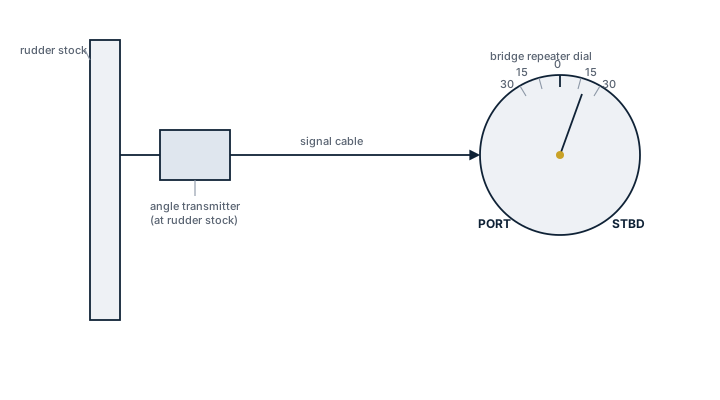
Rudder angle indicator, stock to bridge
Schematic of a rudder angle indicator: a transmitter unit taken directly from the rudder stock sends the actual rudder angle by cable to a port/starboard dial repeater on the bridge.

Main components

Rudder angle transmitter

Mounted on the rudder stock or the tiller arm itself, this is either a mechanical linkage driving a synchro transmitter or, on newer installations, an inductive or magnetic sensor reading stock rotation directly, avoiding a mechanical linkage that can wear or seize.

Signal transmission

The signal reaches the bridge as a synchro/analogue feed on older ships or as a digital NMEA feed on integrated bridge systems, and is usually also fed to the steering gear compartment's own local repeater so engineers working there can see the same reading as the bridge.

Bridge display

At least one repeater is positioned so it is visible from the conning position, with a second commonly fitted at the steering position itself.

Regulations and class

SOLAS Chapter V regulation 19 requires a rudder angle indicator that is functionally independent of the steering control system, so that a fault in the autopilot or helm control cannot also blind the bridge to actual rudder position. Class surveys the steering gear including a function test of the RAI as part of periodic steering gear trials, checking that the indicated angle matches the rudder's true position at both hard-over limits and amidships.

Typical faults

FaultConsequence
Mechanical linkage wear on an older transmitterIndicated angle drifts from actual angle by a growing offset, most noticeable near the rudder limits
Synchro transmitter failureIndicator freezes on a fixed reading while the rudder continues to move, giving the bridge false confidence
Calibration not re-checked after steering gear overhaulZero point shifted, so amidships on the rudder no longer reads zero on the indicator
Cable or connector corrosion in the steering gear compartmentIntermittent or erratic reading in a compartment that is often warm, humid and hard to keep dry

What to look for in a supplier

  • Transmitter type matched to the existing steering gear's stock or tiller geometry, rotary or linear as fitted
  • Enclosure rating suited to a steering flat environment rather than a bridge-console-grade unit
  • Output format compatible with the ship's integrated bridge or autopilot interface without an added converter
  • Straightforward field calibration procedure, since this is checked at every steering gear test

Before departure, compare the RAI reading against the rudder visually amidships if it can be seen, or against the steering gear compartment's local gauge; a discrepancy here is one of the more reliable early signs of a developing helm-order chain fault, well before it shows up as a steering casualty.
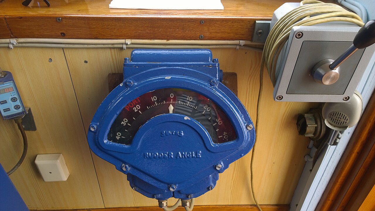
Rudder angle indicator
Rudder angle indicator. Photo: Work from Hummelhummel uploaded by Commons user Buonasera are releas, CC BY-SA 4.0, via Wikimedia Commons

6 manufacturers · 6 models

Böning

1
Böning Rudder Angle Display
Rudder Angle Display
±45° MFD · Navigation Data / Sensor · MFD bridge display
Range
±45°
Display type
MFD
Common Failures & Inspection Points
  • Display panel aging
  • Touch interface issues
  • Network dependency
Service: Böning display can show rudder angle among other bridge data.
Spare Parts: Böning: Ersatzteile per Hersteller-Netzwerk. Lead time: 1-4 Wochen. Backup-Systeme an Bord pflichtgemäß.
Strengths
  • High‑resolution, colour graphics improve readability of rudder position and related data
  • Fully integrable with existing Böning bridge suites via NMEA/ Ethernet networks
  • Configurable layout allows the rudder angle to be combined with other bridge information on one screen
  • Touch interface enables quick manual calibration or zeroing directly from the display
Weaknesses
  • Display panel can age, leading to reduced brightness or dead pixels over long service life
  • Touch‑screen may become less responsive in harsh marine environments (salt spray, temperature extremes)
  • Relies on a stable network connection; loss of NMEA data disables the indicator
Typical Vessels: TankerContainer shipBulk carrierCruise linerOffshore supply vessel
Certifications: IMO Performance StandardDNV
Decision Guide: Choose if you already use Böning bridge equipment or need a high‑resolution, configurable rudder angle readout that can be integrated with other navigation data. Avoid if your vessel operates in environments where network reliability is poor or you prefer a simple analog indicator with no touch interface.
Use Cases: The display is normally mounted on the main bridge console and used during maneuvering, docking, dynamic positioning and training to give the officer of the watch an immediate visual cue of rudder position alongside speed, heading and other bridge data.

DEIF

1
Rudder Angle Indicator
±45° · Navigation Data / Sensor · digital rudder angle indicator
Range
±45°
Common Failures & Inspection Points
  • LED segment failure
  • Signal input mismatch
  • Power supply issues
Service: Danish quality marine instruments.
Spare Parts: Deif: Ersatzteile per Hersteller-Netzwerk. Lead time: 1-4 Wochen. Backup-Systeme an Bord pflichtgemäß.
Strengths
  • Compact, easy‑to‑read LED display
  • Integrated communication with DEIF automation systems
  • Danish engineering reputation for reliability
  • Wide ±45° measurement range suitable for most commercial ships
  • Simple installation using standard signal inputs
Weaknesses
  • LED segment failures have been reported in the field
  • Limited to a ±45° range – not suitable for vessels with larger steering angles
  • Requires compatible signal input; mismatches can cause errors
  • Power‑supply sensitivity may lead to occasional outages
  • Potentially higher unit cost compared with basic analog indicators
Typical Vessels: TankerContainer shipBulk carrierCruise linerOffshore support vessel
Decision Guide: Choose if: you need a reliable, digital rudder angle read‑out that integrates smoothly with DEIF control suites and the vessel’s steering range stays within ±45°. Avoid if: budget constraints favour cheaper analog units, or the ship requires a larger measurement range or has non‑standard signal interfaces.
Use Cases: Mounted on bridge consoles of new builds or retrofits to provide continuous rudder angle feedback during navigation, maneuvering, and dynamic positioning operations; often linked to alarm systems and autopilot controllers in integrated bridge systems.

Kongsberg Maritime

1
Rudder Angle Indicator
±45° · Navigation Data / Sensor · Rudder angle indication system
Range
±45°
Common Failures & Inspection Points
  • Sensor seal at rudder trunk
  • Signal noise
  • Display LED aging
Service: Kongsberg rudder indicator. Integrated with autopilot.
Spare Parts: Kongsberg: Ersatzteile per Hersteller-Netzwerk. Lead time: 1-4 Wochen. Backup-Systeme an Bord pflichtgemäß.
Strengths
  • Accurate ±45° measurement with marine‑grade sensors
  • Seamless integration with Kongsberg autopilot packages
  • Robust, corrosion‑resistant housing suitable for harsh sea environments
  • Proven reliability in commercial fleets worldwide
  • Clear LED display provides instant visual feedback to bridge watchstanders
Weaknesses
  • Sensor seal at the rudder trunk is a known wear point requiring periodic inspection
  • Signal noise can appear under high vibration or electrical interference
  • LED display brightness degrades over time, necessitating panel replacement
  • Angular range limited to ±45°, unsuitable for vessels needing full‑circle indication
  • Requires regular calibration and maintenance to retain accuracy
Typical Vessels: TankerContainer shipBulk carrierCruise linerOffshore supply vessel
Certifications: IMO Type ApprovalDNV Class Approval
Decision Guide: Choose if the vessel already uses Kongsberg bridge equipment or needs a reliable, integrated rudder angle read‑out for autopilot control and bridge monitoring. Avoid if a full 360° indication is required, maintenance windows are extremely limited, or the operator prefers a non‑LED display technology.
Use Cases: Installed on the main bridge of merchant vessels to give the officer of the watch an immediate visual cue of rudder position while the autopilot continuously receives the angle for precise course keeping. Commonly found on tankers, container ships and bulk carriers where integrated Kongsberg navigation suites are deployed.

Raytheon Anschütz

1
Rudder Angle Indicator
±45° · Navigation Data / Sensor · Hall‑effect/potentiometer rudder sensor
Range
±45°
Sensor type
Potentiometer/Hall-effect
Common Failures & Inspection Points
  • Potentiometer wear at rudder stock
  • Display calibration drift
  • Cable water ingress
Service: Part of Synapsis bridge. Potentiometer or Hall-effect sensor.
Spare Parts: Raytheon Anschütz: Ersatzteile per Hersteller-Netzwerk. Lead time: 1-4 Wochen. Backup-Systeme an Bord pflichtgemäß.
Strengths
  • Integrated with Raytheon Anschütz Synapsis bridge suite for seamless data exchange
  • Dual sensor option (potentiometer or Hall‑effect) allows selection based on maintenance preference
  • ±45° range covers the majority of conventional ship rudders
  • Proven manufacturer reputation for reliability in navigation equipment
Weaknesses
  • Potentiometer version is prone to wear at the rudder stock, increasing maintenance intervals
  • Display can develop calibration drift, requiring regular verification
  • Cable assemblies are vulnerable to water ingress in harsh marine environments
  • Limited angular range compared with specialised high‑angle rudders
Typical Vessels: Container shipTankerBulk carrierGeneral cargo vesselPassenger ferry
Certifications: IMO Type Approval
Decision Guide: Choose if: you already operate a Raytheon Anschütz Synapsis bridge or need a proven, integrated rudder angle display with selectable sensor technology. Avoid if: your vessel uses high‑angle rudders beyond ±45°, or you require a completely water‑tight cable system without additional protection.
Use Cases: Installed on the steering gear assembly of merchant vessels to feed real‑time rudder position data to bridge consoles, autopilots and alarm systems; commonly fitted during newbuild outfitting or as part of retrofit projects for ships equipped with conventional mechanical rudders.

Tokyo Keiki

1
Rudder Angle Indicator
±45° · Navigation Data / Sensor · Analog synchro rudder angle indicator
Range
±45°
Display type
Analog
Common Failures & Inspection Points
  • Synchro signal issues
  • Meter movement wear
  • Lighting bulb replacement
Service: Traditional analog display. Reliable mechanical meter.
Spare Parts: Tokyo Keiki: Ersatzteile per Hersteller-Netzwerk. Lead time: 1-4 Wochen. Backup-Systeme an Bord pflichtgemäß.
Strengths
  • Proven mechanical reliability with minimal electronic components
  • Very low power consumption, suitable for vessels with limited bridge power budgets
  • Simple visual read‑out that crew members can interpret instantly
  • Easy to service – meter movement wear and bulb replacement are straightforward tasks
  • Compatible with existing synchro steering control loops on many older ships
Weaknesses
  • Limited resolution compared with modern digital displays
  • Requires periodic calibration to maintain accuracy
  • Susceptible to synchro signal degradation or wiring faults
  • Analog dial may be hard to read in low‑light conditions without back‑lighting
  • Cannot feed data directly into integrated bridge management systems
Typical Vessels: Bulk CarrierContainer ShipTankerRo‑Ro FerryGeneral Cargo Vessel
Decision Guide: Choose if: you need a rugged, low‑maintenance rudder angle display that works with existing synchro steering gear and power is at a premium. Avoid if: the bridge requires digital integration, high‑resolution data logging, or remote monitoring capabilities.
Use Cases: Installed on the navigation bridge of conventional ships to give the helmsman an immediate visual cue of rudder position, often as part of a fully mechanical synchro steering system on vessels that prioritize simplicity and redundancy over electronic sophistication.

Wema

1
Wema Marine Rudder Indicator
Marine Rudder Indicator
±45° · Navigation Data / Sensor
Range
±45°
Common Failures & Inspection Points
  • Sensor cable corrosion
  • Display fogging
  • Mounting vibration
Service: Norwegian manufacturer. Simple and reliable.
Spare Parts: Wema: Ersatzteile per Hersteller-Netzwerk. Lead time: 1-4 Wochen. Backup-Systeme an Bord pflichtgemäß.
Strengths
  • Simple mechanical sensor with minimal electronic complexity – easy to install and maintain
  • Robust housing designed for harsh marine environments; proven reliability on Norwegian vessels
  • Low power consumption compared with fully digital or networked alternatives
  • Direct, real‑time visual feedback that does not rely on bridge network integration
Weaknesses
  • Limited measurement range (±45°) may be insufficient for vessels with larger steering angles
  • Mechanical sensor cable is prone to corrosion if not regularly inspected and protected
  • Display can fog in high humidity or temperature‑gradient conditions, reducing readability
  • Vibration at the mounting point can introduce reading errors unless properly damped
Typical Vessels: Coastal cargo vesselsOffshore supply shipsFerries and passenger craftSmall tankersFishing vessels
Decision Guide: Choose if you need a straightforward, low‑cost rudder angle display on a vessel with modest steering angles and prefer proven mechanical reliability. Avoid if the ship requires wide‑range measurement, integrated NMEA/bridge network data, or operates in environments where vibration and humidity are extreme without additional mitigation.
Use Cases: Installed on the bridge of small to medium commercial vessels to give helmsmen immediate visual confirmation of rudder position, often paired with basic autopilot systems or used as a backup indicator on training ships.