"> Bridge CCTV System - Equipment Database

Bridge CCTV System

medium 27 models total

Bridge CCTV covers the cameras and recorders that give the officer of the watch a view of blind spots around the hull, mooring decks and machinery spaces, and that, unlike the VDR, are not a mandatory SOLAS fit on most vessel types.

Read more — Bridge CCTV System explained

What defines a Bridge CCTV system

Bridge CCTV is a network of fixed and pan-tilt-zoom cameras feeding monitors on the bridge and, usually, a recorder, covering areas the officer of the watch cannot see directly: the bow and stern in confined manoeuvring, mooring decks during berthing, cargo areas, engine room and steering gear compartment, lifeboat embarkation stations, and pilot boarding points. It sits apart from the Voyage Data Recorder in both purpose and status: the VDR is a mandatory SOLAS fit that continuously records bridge audio, radar and instrument data for accident investigation and, on many ships, is fed a camera image of the bridge itself; Bridge CCTV is an operational aid chosen by the owner, not required by SOLAS on most vessel types, and its footage is a management and safety tool rather than a legal recording requirement.
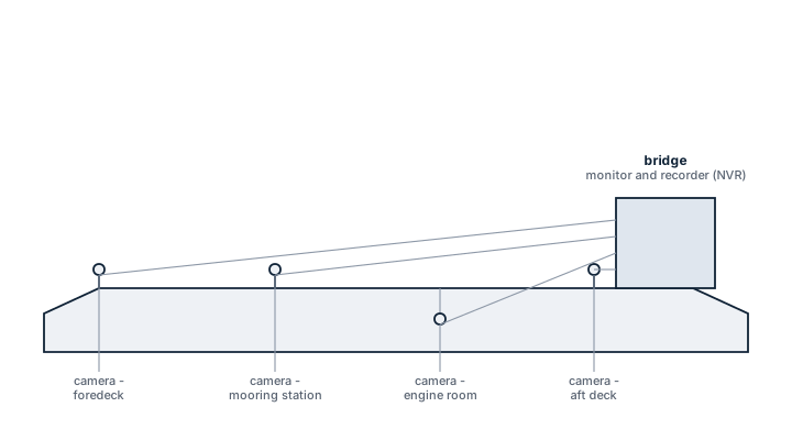
Bridge CCTV camera arrangement
Simplified ship side profile showing CCTV cameras at the foredeck, midship mooring station, engine room and aft deck, all cabled back to the monitor and recorder unit on the bridge.

Main components

Cameras

Fixed cameras cover mooring stations, cargo deck and engine room; a pan-tilt-zoom unit is common on the bridge wings for close manoeuvring and pilot transfer observation. Marine-rated housings are sealed against spray and vibration and most units used outdoors are low-light or infrared capable for night watchkeeping.

Monitors and control console

A multi-view monitor or monitor bank on the bridge, with switching and PTZ control, lets the watchkeeper call up any camera without leaving the conning position.

Recorder

A network video recorder stores footage on a rolling basis; retention period is set by the owner's policy rather than by a fixed rule, commonly from a few days up to 90 days depending on storage fitted.

Cabling and power supply

Runs are usually fibre or shielded Cat cable to survive the electromagnetic environment of the engine room and radar mast, backed by an uninterruptible supply so recording continues through a short power interruption.

Selection and sizing

Camera count and placement follow the specific blind spots of the hull form and cargo arrangement rather than a fixed rule: a container ship needs bow, stern and lashing-deck coverage; a tanker adds manifold and cargo deck cameras for spill watch; a passenger vessel adds embarkation stations and mustering areas. Resolution and low-light performance matter more than raw camera count for usable footage at night. Storage capacity is set by camera count, resolution and required retention period, and should be checked against the recorder's actual usable capacity rather than its nominal drive size.

Regulations and class

Bridge CCTV is not a SOLAS carriage requirement in itself; where cameras are fitted they still fall under general electrical and EMC installation rules for bridge equipment and, for cargo-area cameras on tankers and gas carriers, may be referenced in the ship's oil or gas spill response procedures. Passenger ships increasingly carry CCTV covering embarkation and mustering stations as part of the safety management system rather than a class notation. Where a camera feed is also routed into the VDR as the mandatory bridge image, that specific camera and its recording path do fall under VDR performance standards and survey.

Typical faults

  • Housing seal failure — moisture ingress fogs or shorts an outdoor camera, usually first noticed as a degraded image before total failure.
  • Recorder storage full or drive failure — footage silently stops being retained; without a proactive check this is only discovered when footage is needed and is not there.
  • Infrared/low-light failure — a night-blind camera still shows a picture in daylight testing, so faults are easy to miss unless checked after dark.
  • Cable damage near the mast or exhaust — vibration and heat cycling degrade cable runs over years, producing intermittent signal loss that is hard to trace.

What to look for in a supplier

  • Marine-rated camera housings with a stated IP rating and vibration certification for mast and deck mounting.
  • Low-light or infrared performance data, not just daytime resolution figures.
  • Recorder storage sized with margin over the owner's stated retention policy, and remote access for shore-side review.
  • Spares availability for the specific camera and recorder model, since marine CCTV product lines change faster than most bridge equipment.

Test every outdoor camera after dark at least once a voyage: a fogged housing or a dead infrared illuminator is invisible on a daytime picture and only shows up exactly when the footage would have mattered most.

24 manufacturers · 27 models

FLIR

2
M364C Marine Thermal unverified
Resolution
640x512
Thermal
ja
Visible plus thermal
ja
Common Failures & Inspection Points
  • Sensor, antenna or transducer fault, typically indicated by missing, unstable or implausible navigation data
  • Power-supply or processor failure, typically indicated by blank display, rebooting or unavailable function
  • Network/interface fault, typically indicated by missing data on connected bridge systems or communication alarms
  • Cable/connector corrosion or water ingress, typically indicated by intermittent operation or signal loss
  • Recording/storage or software fault on recorder-type equipment, typically indicated by data gaps, recording alarms or failed playback
Service: Check self-tests, sensor/transducer condition, data interfaces, time/position inputs, recording status where applicable, power supplies and alarm history; performance tests and calibration must follow approved manufacturer and statutory procedures.
Spare Parts: Carry critical fuses, power supplies, interface modules, storage media where approved, sensors/transducers or display peripherals according to equipment criticality.
Use Cases: Used on merchant, passenger, offshore and naval vessels for navigation, bridge situational awareness, environmental sensing and voyage-data recording. This entry applies specifically to the Bridge CCTV System variant identified as FLIR M364C Marine Thermal.
M232 Marine Thermal unverified
Resolution
320x256
Thermal
ja
Common Failures & Inspection Points
  • Loss of electrical, hydraulic, pneumatic, fluid, or other service supply from a protection trip, leakage, blockage, or upstream fault results in failed starting or loss of function
  • Mechanical wear, corrosion, fouling, or contamination of moving and wetted parts causes increased noise, leakage, sticking, vibration, or reduced performance
  • Seal, gasket, hose, cable, or connection deterioration from age, heat, vibration, or environmental exposure produces visible leakage, intermittent signals, or loss of pressure
  • Sensor, switch, actuator, relay, or control-system faults cause incorrect indication, nuisance alarms, failed automatic sequences, or loss of remote control
  • Incorrect adjustment, assembly, or maintenance leads to unstable operation, recurrent alarms, or performance that differs from the vessel's normal baseline
Service: Inspect the unit for leakage, corrosion, contamination, loose connections, abnormal noise or vibration, condition of guards and mountings, service supplies, controls, alarms, and functional performance. Use maintenance history to identify deterioration trends and refer to manufacturer documentation for exact settings, tolerances, test values, and overhaul criteria.
Spare Parts: Keep the manufacturer-recommended seals and gaskets, filters where fitted, fuses or protection items, common sensors and switches, and critical actuator, control, or wear components appropriate to the installed configuration. Exact part numbers and quantities must come from the manufacturer spare-parts documentation.
Use Cases: Used on vessel types fitted with navigation & bridge equipment equipment, including merchant, offshore, passenger, fishing, or workboat installations where this specific bridge cctv system duty is required.

Glamox Marine

2
CGL800 Nav Light Panel unverified
Type
navigation_light_controller
IMO Compliant
ja
Common Failures & Inspection Points
  • Camera lens contamination, water ingress or physical damage causes blurred, obscured or missing images
  • Power, PoE or supply faults cause one or more cameras to go offline
  • Network, switch or cable faults cause intermittent video, frozen images or lost channels
  • Recorder or storage faults cause missing historical footage or storage alarms
  • Incorrect camera alignment, focus or low-light settings leaves critical areas outside the useful field of view
Service: Inspect camera housings, lenses, mounting, cabling, network equipment, displays and recorder status. Confirm each critical view is clear and correctly aligned and review storage or recording alarms. Check time synchronization where recordings may be used operationally or for incident review. Refer to the manufacturer documentation for the exact figure for storage, network and environmental limits.
Spare Parts: Carry replacement cameras for critical positions where practical, power supplies, network switches or injectors, connectors, storage devices and cleaning materials.
Use Cases: Bridge wing monitoring, deck awareness, security observation and operational recording.
CGL100 Search Light unverified
Type
signal_light
IMO Compliant
ja
Common Failures & Inspection Points
  • Sensor, antenna or transducer fault, typically indicated by missing, unstable or implausible navigation data
  • Power-supply or processor failure, typically indicated by blank display, rebooting or unavailable function
  • Network/interface fault, typically indicated by missing data on connected bridge systems or communication alarms
  • Cable/connector corrosion or water ingress, typically indicated by intermittent operation or signal loss
  • Recording/storage or software fault on recorder-type equipment, typically indicated by data gaps, recording alarms or failed playback
Service: Check self-tests, sensor/transducer condition, data interfaces, time/position inputs, recording status where applicable, power supplies and alarm history; performance tests and calibration must follow approved manufacturer and statutory procedures.
Spare Parts: Carry critical fuses, power supplies, interface modules, storage media where approved, sensors/transducers or display peripherals according to equipment criticality.
Use Cases: Used on merchant, passenger, offshore and naval vessels for navigation, bridge situational awareness, environmental sensing and voyage-data recording. This entry applies specifically to the Bridge CCTV System variant identified as Glamox CGL100 Search Light.

Perko Marine

2
3500-Series Signal Light unverified
Type
signal_light
IMO Compliant
ja
Common Failures & Inspection Points
  • Camera lens contamination, water ingress or physical damage causes blurred, obscured or missing images
  • Power, PoE or supply faults cause one or more cameras to go offline
  • Network, switch or cable faults cause intermittent video, frozen images or lost channels
  • Recorder or storage faults cause missing historical footage or storage alarms
  • Incorrect camera alignment, focus or low-light settings leaves critical areas outside the useful field of view
Service: Inspect camera housings, lenses, mounting, cabling, network equipment, displays and recorder status. Confirm each critical view is clear and correctly aligned and review storage or recording alarms. Check time synchronization where recordings may be used operationally or for incident review. Refer to the manufacturer documentation for the exact figure for storage, network and environmental limits.
Spare Parts: Carry replacement cameras for critical positions where practical, power supplies, network switches or injectors, connectors, storage devices and cleaning materials.
Use Cases: Bridge wing monitoring, deck awareness, security observation and operational recording.
Navigation Light Controller unverified
Type
navigation_light_controller
IMO Compliant
ja
Common Failures & Inspection Points
  • Sensor, antenna or transducer fault caused by damage, fouling, water ingress or electronics failure, resulting in missing, unstable or implausible navigation data
  • Power-supply failure caused by breaker, converter or wiring faults, resulting in loss of indication or repeated restarts
  • Network or interface failure caused by damaged cabling, port faults or configuration changes, resulting in loss of data to connected bridge systems
  • Display, processor or control failure caused by hardware or software faults, resulting in frozen, blank or unavailable functions
  • Calibration, alignment or configuration error caused by incorrect setup or maintenance, resulting in persistent disagreement with independent references
Service: Compare indicated data and system response with independent references and investigate persistent disagreement. Inspect sensors, antennas, cabling, power supplies, displays and network interfaces applicable to the installation. Verify required alarms and outputs to connected bridge systems using approved procedures. Back up configuration before authorized software or hardware changes. Protect exposed sensors and antennas from paint, deposits and water ingress. Refer to the manufacturer documentation for the exact figure for test, calibration, alignment and recovery procedures.
Spare Parts: Keep fuses, selected power-supply and interface modules, cables or connectors and manufacturer-recommended sensor or electronic spares. Replacement core units must remain compatible with the approved bridge installation. Preserve calibration, identity and configuration data.
Use Cases: It is used for bridge navigation and monitoring on merchant ships, passenger vessels, offshore units or other vessel types where this equipment category is fitted.

AMI Marine

1
BNWAS-500 unverified
Type
BNWAS
IMO Compliant
ja
Alarm stages
3
Common Failures & Inspection Points
  • Sensor or antenna degradation caused by contamination, damage, ageing or poor exposure can produce missing, unstable or implausible data
  • Connector, cable or network faults caused by vibration, corrosion or disturbed terminations can cause intermittent data loss or interface alarms
  • Power-supply or internal electronics failure caused by ageing, heat or poor ventilation can result in resets, blank indications or complete loss of function
  • Configuration or software errors after service or replacement can cause incorrect data, rejected inputs or loss of communication with other bridge equipment
  • Mechanical damage or water ingress at exposed components can lead to erratic readings, repeated alarms or loss of the affected channel
Service: Inspect exposed sensors or antennas, cable routes, connectors, power supplies, displays and network interfaces. Confirm that indicated or recorded data is plausible and that built-in tests and alarms operate. Compare configuration and test results with the vessel's approved records and manufacturer documentation.
Spare Parts: Keep maker-recommended fuses, connectors, sensor accessories, fans, interface or power modules and other approved line-replaceable items that match the installed configuration.
Use Cases: Commercial ships, passenger vessels, offshore vessels and workboats requiring bridge navigation, recording, environmental or traffic information.

Axis Communications

1
Axis Q6135-LE Marine PTZ unverified
Resolution
1080p
Ptz
ja
Ir range (m)
200
IMO Compliant
nein
Ingress Protection (IP)
IP66
Common Failures & Inspection Points
  • Loss of sensor input or network communication can remove or freeze displayed data, noticed as invalid-data flags, alarms or missing targets
  • Antenna, transducer or external-sensor contamination or damage can degrade performance, seen as weak, erratic or implausible indications
  • Power-supply or internal electronics faults can cause resets or loss of function, noticed as blank displays, rebooting or system alarms
  • Configuration or calibration drift can produce inaccurate output, seen as disagreement with independent bridge instruments
  • Connector corrosion or water ingress can create intermittent faults, noticed as performance changing with vibration, weather or vessel movement
Service: Inspect displays, external sensors, antennas or transducers, connectors, cabling, power supplies and network interfaces. Compare outputs against independent bridge references where practical and review alarms or self-test indications. Calibration limits and any mandatory test procedure must follow the approved manufacturer and vessel documentation.
Spare Parts: Typical spares include approved fuses, interface cables or connectors, lamps or display consumables, sensor accessories and manufacturer-recommended electronic modules where carried.
Use Cases: Used on merchant ships, offshore vessels, passenger ships and specialized craft as part of the bridge navigation and monitoring suite.

Consilium Marine

1
SAL BNWAS-200 unverified
Type
BNWAS
IMO Compliant
ja
Alarm stages
3
Common Failures & Inspection Points
  • Loss of electrical, hydraulic, pneumatic, fluid, or other service supply from a protection trip, leakage, blockage, or upstream fault results in failed starting or loss of function
  • Mechanical wear, corrosion, fouling, or contamination of moving and wetted parts causes increased noise, leakage, sticking, vibration, or reduced performance
  • Seal, gasket, hose, cable, or connection deterioration from age, heat, vibration, or environmental exposure produces visible leakage, intermittent signals, or loss of pressure
  • Sensor, switch, actuator, relay, or control-system faults cause incorrect indication, nuisance alarms, failed automatic sequences, or loss of remote control
  • Incorrect adjustment, assembly, or maintenance leads to unstable operation, recurrent alarms, or performance that differs from the vessel's normal baseline
Service: Inspect the unit for leakage, corrosion, contamination, loose connections, abnormal noise or vibration, condition of guards and mountings, service supplies, controls, alarms, and functional performance. Use maintenance history to identify deterioration trends and refer to manufacturer documentation for exact settings, tolerances, test values, and overhaul criteria.
Spare Parts: Keep the manufacturer-recommended seals and gaskets, filters where fitted, fuses or protection items, common sensors and switches, and critical actuator, control, or wear components appropriate to the installed configuration. Exact part numbers and quantities must come from the manufacturer spare-parts documentation.
Use Cases: Used on vessel types fitted with navigation & bridge equipment equipment, including merchant, offshore, passenger, fishing, or workboat installations where this specific bridge cctv system duty is required.

Daeyang Marine

1
DAE-100 Search Light unverified
Type
signal_light
IMO Compliant
ja
Common Failures & Inspection Points
  • Camera lens contamination, water ingress or physical damage causes blurred, obscured or missing images
  • Power, PoE or supply faults cause one or more cameras to go offline
  • Network, switch or cable faults cause intermittent video, frozen images or lost channels
  • Recorder or storage faults cause missing historical footage or storage alarms
  • Incorrect camera alignment, focus or low-light settings leaves critical areas outside the useful field of view
Service: Inspect camera housings, lenses, mounting, cabling, network equipment, displays and recorder status. Confirm each critical view is clear and correctly aligned and review storage or recording alarms. Check time synchronization where recordings may be used operationally or for incident review. Refer to the manufacturer documentation for the exact figure for storage, network and environmental limits.
Spare Parts: Carry replacement cameras for critical positions where practical, power supplies, network switches or injectors, connectors, storage devices and cleaning materials.
Use Cases: Bridge wing monitoring, deck awareness, security observation and operational recording.

Danelec Marine

1
DM-BNWAS unverified
Type
BNWAS
IMO Compliant
ja
Alarm stages
3
Common Failures & Inspection Points
  • Loss of electrical, hydraulic, pneumatic, fluid, or other service supply from a protection trip, leakage, blockage, or upstream fault results in failed starting or loss of function
  • Mechanical wear, corrosion, fouling, or contamination of moving and wetted parts causes increased noise, leakage, sticking, vibration, or reduced performance
  • Seal, gasket, hose, cable, or connection deterioration from age, heat, vibration, or environmental exposure produces visible leakage, intermittent signals, or loss of pressure
  • Sensor, switch, actuator, relay, or control-system faults cause incorrect indication, nuisance alarms, failed automatic sequences, or loss of remote control
  • Incorrect adjustment, assembly, or maintenance leads to unstable operation, recurrent alarms, or performance that differs from the vessel's normal baseline
Service: Inspect the unit for leakage, corrosion, contamination, loose connections, abnormal noise or vibration, condition of guards and mountings, service supplies, controls, alarms, and functional performance. Use maintenance history to identify deterioration trends and refer to manufacturer documentation for exact settings, tolerances, test values, and overhaul criteria.
Spare Parts: Keep the manufacturer-recommended seals and gaskets, filters where fitted, fuses or protection items, common sensors and switches, and critical actuator, control, or wear components appropriate to the installed configuration. Exact part numbers and quantities must come from the manufacturer spare-parts documentation.
Use Cases: Used on vessel types fitted with navigation & bridge equipment equipment, including merchant, offshore, passenger, fishing, or workboat installations where this specific bridge cctv system duty is required.

DHR

1
350CS Signal Light unverified
Type
signal_light
IMO Compliant
ja
Common Failures & Inspection Points
  • Camera lens contamination, water ingress or physical damage causes blurred, obscured or missing images
  • Power, PoE or supply faults cause one or more cameras to go offline
  • Network, switch or cable faults cause intermittent video, frozen images or lost channels
  • Recorder or storage faults cause missing historical footage or storage alarms
  • Incorrect camera alignment, focus or low-light settings leaves critical areas outside the useful field of view
Service: Inspect camera housings, lenses, mounting, cabling, network equipment, displays and recorder status. Confirm each critical view is clear and correctly aligned and review storage or recording alarms. Check time synchronization where recordings may be used operationally or for incident review. Refer to the manufacturer documentation for the exact figure for storage, network and environmental limits.
Spare Parts: Carry replacement cameras for critical positions where practical, power supplies, network switches or injectors, connectors, storage devices and cleaning materials.
Use Cases: Bridge wing monitoring, deck awareness, security observation and operational recording.

Francis Searchlights

1
FH200 Daylight Signal unverified
Type
signal_light
IMO Compliant
ja
Common Failures & Inspection Points
  • Sensor, antenna or transducer fault caused by damage, fouling, water ingress or electronics failure, resulting in missing, unstable or implausible navigation data
  • Power-supply failure caused by breaker, converter or wiring faults, resulting in loss of indication or repeated restarts
  • Network or interface failure caused by damaged cabling, port faults or configuration changes, resulting in loss of data to connected bridge systems
  • Display, processor or control failure caused by hardware or software faults, resulting in frozen, blank or unavailable functions
  • Calibration, alignment or configuration error caused by incorrect setup or maintenance, resulting in persistent disagreement with independent references
Service: Compare indicated data and system response with independent references and investigate persistent disagreement. Inspect sensors, antennas, cabling, power supplies, displays and network interfaces applicable to the installation. Verify required alarms and outputs to connected bridge systems using approved procedures. Back up configuration before authorized software or hardware changes. Protect exposed sensors and antennas from paint, deposits and water ingress. Refer to the manufacturer documentation for the exact figure for test, calibration, alignment and recovery procedures.
Spare Parts: Keep fuses, selected power-supply and interface modules, cables or connectors and manufacturer-recommended sensor or electronic spares. Replacement core units must remain compatible with the approved bridge installation. Preserve calibration, identity and configuration data.
Use Cases: It is used for bridge navigation and monitoring on merchant ships, passenger vessels, offshore units or other vessel types where this equipment category is fitted.

Furuno

1
BR-500 BNWAS unverified
Type
BNWAS
IMO Compliant
ja
Alarm stages
3
Common Failures & Inspection Points
  • Sensor or antenna degradation caused by contamination, damage, ageing or poor exposure can produce missing, unstable or implausible data
  • Connector, cable or network faults caused by vibration, corrosion or disturbed terminations can cause intermittent data loss or interface alarms
  • Power-supply or internal electronics failure caused by ageing, heat or poor ventilation can result in resets, blank indications or complete loss of function
  • Configuration or software errors after service or replacement can cause incorrect data, rejected inputs or loss of communication with other bridge equipment
  • Mechanical damage or water ingress at exposed components can lead to erratic readings, repeated alarms or loss of the affected channel
Service: Inspect exposed sensors or antennas, cable routes, connectors, power supplies, displays and network interfaces. Confirm that indicated or recorded data is plausible and that built-in tests and alarms operate. Compare configuration and test results with the vessel's approved records and manufacturer documentation.
Spare Parts: Keep maker-recommended fuses, connectors, sensor accessories, fans, interface or power modules and other approved line-replaceable items that match the installed configuration.
Use Cases: Commercial ships, passenger vessels, offshore vessels and workboats requiring bridge navigation, recording, environmental or traffic information.

Hella Marine

1
NaviLED Pro Panel unverified
Type
navigation_light_controller
IMO Compliant
ja
Common Failures & Inspection Points
  • Camera lens contamination, water ingress or physical damage causes blurred, obscured or missing images
  • Power, PoE or supply faults cause one or more cameras to go offline
  • Network, switch or cable faults cause intermittent video, frozen images or lost channels
  • Recorder or storage faults cause missing historical footage or storage alarms
  • Incorrect camera alignment, focus or low-light settings leaves critical areas outside the useful field of view
Service: Inspect camera housings, lenses, mounting, cabling, network equipment, displays and recorder status. Confirm each critical view is clear and correctly aligned and review storage or recording alarms. Check time synchronization where recordings may be used operationally or for incident review. Refer to the manufacturer documentation for the exact figure for storage, network and environmental limits.
Spare Parts: Carry replacement cameras for critical positions where practical, power supplies, network switches or injectors, connectors, storage devices and cleaning materials.
Use Cases: Bridge wing monitoring, deck awareness, security observation and operational recording.

Hikvision Marine

1
DS-2CD6365G0E-IVS Marine unverified
Resolution
6MP
Ptz
nein
Ir range (m)
30
Ingress Protection (IP)
IP67
Common Failures & Inspection Points
  • Camera or lens degradation caused by salt, water ingress, dirt or electronics failure, resulting in blurred, intermittent or missing video
  • Power-supply failure caused by breaker, converter or wiring faults, resulting in loss of the equipment or repeated restarts
  • Network or interface failure caused by damaged cabling, port faults or configuration changes, resulting in loss of data to connected systems
  • Display, processor or control failure caused by hardware or software faults, resulting in frozen indications, alarms or unavailable functions
  • Incorrect configuration or time, position or sensor input caused by setup or upstream faults, resulting in misleading or incomplete information
Service: Inspect sensors, antennas, transducers, cameras, cabling, power supplies and network interfaces applicable to the installed equipment. Compare displayed information with independent references where possible and investigate recurring alarms or missing channels. Verify required outputs to other bridge systems and preserve configuration before approved software or hardware maintenance. Clean exposed sensors and optical surfaces without damaging coatings or seals. Check backup power or recording arrangements where applicable. Refer to the manufacturer documentation for the exact figure for test, calibration, update and recovery procedures.
Spare Parts: Keep fuses, selected power-supply and interface modules, cables or connectors, storage media where applicable and manufacturer-recommended sensor or electronic spares. Replacement core units must remain compatible with the approved bridge installation. Preserve configuration and recorded setup data.
Use Cases: Bridge navigation, monitoring, recording and maritime safety information functions on merchant ships, passenger vessels, offshore units and workboats.

Jotron

1
Tron BNWAS-100 unverified
Type
BNWAS
IMO Compliant
ja
Alarm stages
3
Common Failures & Inspection Points
  • Sensor, camera or input failure causes missing data, blank images or channel alarms
  • Power-supply, UPS or network faults cause system restart, loss of recording or unavailable remote status
  • Storage-media or recorder faults cause gaps in retained data or failed self-tests
  • Incorrect time, configuration or interface data causes inconsistent records or false alarms
  • Control, acknowledgment or communication faults cause unavailable watchkeeping or security functions
Service: Review self-tests, event logs, time synchronization, power supplies, storage status and connected sensor channels. Verify required alarms and communication paths under the approved procedure without sending unauthorized security alerts. Check data quality and retention status where applicable. Refer to manufacturer and statutory documentation for the exact figure for test and retention criteria.
Spare Parts: Carry approved storage or recorder modules where supported, power supplies, network interfaces, camera parts, fuses and backed-up configuration data.
Use Cases: Voyage recording, bridge watchkeeping, onboard surveillance and statutory security functions.

JRC

1
JBN-100 BNWAS unverified
Type
BNWAS
IMO Compliant
ja
Alarm stages
3
Common Failures & Inspection Points
  • Loss of electrical, hydraulic, pneumatic, or other service supply caused by a tripped protection device, leakage, blockage, or upstream fault results in failed starting or loss of function
  • Mechanical wear, corrosion, fouling, or contamination of moving and wetted parts causes increased noise, leakage, sticking, vibration, or reduced performance
  • Seal, gasket, hose, cable, or connection deterioration from age, heat, vibration, or environmental exposure produces visible leakage, intermittent signals, or loss of pressure
  • Sensor, switch, actuator, relay, or control-system faults can cause incorrect indication, nuisance alarms, failed automatic sequences, or loss of remote control
  • Incorrect adjustment, assembly, or maintenance can lead to unstable operation, recurrent alarms, or performance that differs from the vessel's normal baseline
Service: Inspect the unit for leakage, corrosion, contamination, loose connections, abnormal noise or vibration, condition of guards and mountings, service supplies, controls, alarms, and functional performance. Use the vessel maintenance history to identify deterioration trends and refer to the manufacturer documentation for exact settings, tolerances, test values, and overhaul criteria.
Spare Parts: Keep the manufacturer-recommended seals and gaskets, filters where fitted, fuses or protection items, common sensors and switches, and critical actuator, control, or wear components appropriate to the installed configuration. Exact part numbers and quantities must come from the manufacturer spare-parts documentation.
Use Cases: Used on vessel types fitted with navigation & bridge equipment equipment, including merchant, offshore, passenger, fishing, or workboat installations where this specific bridge cctv system duty is required.

Kelvin Hughes

1
BNWAS MK2 unverified
Type
BNWAS
IMO Compliant
ja
Alarm stages
3
Common Failures & Inspection Points
  • Loss of electrical, hydraulic, pneumatic, fluid, or other service supply from a protection trip, leakage, blockage, or upstream fault results in failed starting or loss of function
  • Mechanical wear, corrosion, fouling, or contamination of moving and wetted parts causes increased noise, leakage, sticking, vibration, or reduced performance
  • Seal, gasket, hose, cable, or connection deterioration from age, heat, vibration, or environmental exposure produces visible leakage, intermittent signals, or loss of pressure
  • Sensor, switch, actuator, relay, or control-system faults cause incorrect indication, nuisance alarms, failed automatic sequences, or loss of remote control
  • Incorrect adjustment, assembly, or maintenance leads to unstable operation, recurrent alarms, or performance that differs from the vessel's normal baseline
Service: Inspect the unit for leakage, corrosion, contamination, loose connections, abnormal noise or vibration, condition of guards and mountings, service supplies, controls, alarms, and functional performance. Use maintenance history to identify deterioration trends and refer to manufacturer documentation for exact settings, tolerances, test values, and overhaul criteria.
Spare Parts: Keep the manufacturer-recommended seals and gaskets, filters where fitted, fuses or protection items, common sensors and switches, and critical actuator, control, or wear components appropriate to the installed configuration. Exact part numbers and quantities must come from the manufacturer spare-parts documentation.
Use Cases: Used on vessel types fitted with navigation & bridge equipment equipment, including merchant, offshore, passenger, fishing, or workboat installations where this specific bridge cctv system duty is required.

Lopolight

1
LED Nav Light System unverified
Type
navigation_light_controller
IMO Compliant
ja
Common Failures & Inspection Points
  • Camera lens contamination, water ingress or physical damage causes blurred, obscured or missing images
  • Power, PoE or supply faults cause one or more cameras to go offline
  • Network, switch or cable faults cause intermittent video, frozen images or lost channels
  • Recorder or storage faults cause missing historical footage or storage alarms
  • Incorrect camera alignment, focus or low-light settings leaves critical areas outside the useful field of view
Service: Inspect camera housings, lenses, mounting, cabling, network equipment, displays and recorder status. Confirm each critical view is clear and correctly aligned and review storage or recording alarms. Check time synchronization where recordings may be used operationally or for incident review. Refer to the manufacturer documentation for the exact figure for storage, network and environmental limits.
Spare Parts: Carry replacement cameras for critical positions where practical, power supplies, network switches or injectors, connectors, storage devices and cleaning materials.
Use Cases: Bridge wing monitoring, deck awareness, security observation and operational recording.

Orlaco Marine

1
AF-Zoom Marine Camera unverified
Resolution
1080p
Zoom x
30
Ingress Protection (IP)
IP69K
Common Failures & Inspection Points
  • Sensor, antenna or transducer fault caused by damage, fouling, water ingress or electronics failure, resulting in missing, unstable or implausible navigation data
  • Power-supply failure caused by breaker, converter or wiring faults, resulting in loss of indication or repeated restarts
  • Network or interface failure caused by damaged cabling, port faults or configuration changes, resulting in loss of data to connected bridge systems
  • Display, processor or control failure caused by hardware or software faults, resulting in frozen, blank or unavailable functions
  • Calibration, alignment or configuration error caused by incorrect setup or maintenance, resulting in persistent disagreement with independent references
Service: Compare indicated data and system response with independent references and investigate persistent disagreement. Inspect sensors, antennas, cabling, power supplies, displays and network interfaces applicable to the installation. Verify required alarms and outputs to connected bridge systems using approved procedures. Back up configuration before authorized software or hardware changes. Protect exposed sensors and antennas from paint, deposits and water ingress. Refer to the manufacturer documentation for the exact figure for test, calibration, alignment and recovery procedures.
Spare Parts: Keep fuses, selected power-supply and interface modules, cables or connectors and manufacturer-recommended sensor or electronic spares. Replacement core units must remain compatible with the approved bridge installation. Preserve calibration, identity and configuration data.
Use Cases: It is used for bridge navigation and monitoring on merchant ships, passenger vessels, offshore units or other vessel types where this equipment category is fitted.

Pelco / Schneider

1
Spectra Marine PTZ Camera unverified
Resolution
4K
Ptz
ja
Ingress Protection (IP)
IP66
Common Failures & Inspection Points
  • Loss of sensor input or network communication can remove or freeze displayed data, noticed as invalid-data flags, alarms or missing targets
  • Antenna, transducer or external-sensor contamination or damage can degrade performance, seen as weak, erratic or implausible indications
  • Power-supply or internal electronics faults can cause resets or loss of function, noticed as blank displays, rebooting or system alarms
  • Configuration or calibration drift can produce inaccurate output, seen as disagreement with independent bridge instruments
  • Connector corrosion or water ingress can create intermittent faults, noticed as performance changing with vibration, weather or vessel movement
Service: Inspect displays, external sensors, antennas or transducers, connectors, cabling, power supplies and network interfaces. Compare outputs against independent bridge references where practical and review alarms or self-test indications. Calibration limits and any mandatory test procedure must follow the approved manufacturer and vessel documentation.
Spare Parts: Typical spares include approved fuses, interface cables or connectors, lamps or display consumables, sensor accessories and manufacturer-recommended electronic modules where carried.
Use Cases: Used on merchant ships, offshore vessels, passenger ships and specialized craft as part of the bridge navigation and monitoring suite.

Pharos Marine

1
PM-NAV Controller unverified
Type
navigation_light_controller
IMO Compliant
ja
Common Failures & Inspection Points
  • Camera or lens degradation caused by salt, water ingress, dirt or electronics failure, resulting in blurred, intermittent or missing video
  • Power-supply failure caused by breaker, converter or wiring faults, resulting in loss of the equipment or repeated restarts
  • Network or interface failure caused by damaged cabling, port faults or configuration changes, resulting in loss of data to connected systems
  • Display, processor or control failure caused by hardware or software faults, resulting in frozen indications, alarms or unavailable functions
  • Incorrect configuration or time, position or sensor input caused by setup or upstream faults, resulting in misleading or incomplete information
Service: Inspect sensors, antennas, transducers, cameras, cabling, power supplies and network interfaces applicable to the installed equipment. Compare displayed information with independent references where possible and investigate recurring alarms or missing channels. Verify required outputs to other bridge systems and preserve configuration before approved software or hardware maintenance. Clean exposed sensors and optical surfaces without damaging coatings or seals. Check backup power or recording arrangements where applicable. Refer to the manufacturer documentation for the exact figure for test, calibration, update and recovery procedures.
Spare Parts: Keep fuses, selected power-supply and interface modules, cables or connectors, storage media where applicable and manufacturer-recommended sensor or electronic spares. Replacement core units must remain compatible with the approved bridge installation. Preserve configuration and recorded setup data.
Use Cases: Bridge navigation, monitoring, recording and maritime safety information functions on merchant ships, passenger vessels, offshore units and workboats.

Phoenix Marine

1
PH-1000 Signal Lamp unverified
Type
signal_light
IMO Compliant
ja
Common Failures & Inspection Points
  • Sensor, antenna or transducer fault, typically indicated by missing, unstable or implausible navigation data
  • Power-supply or processor failure, typically indicated by blank display, rebooting or unavailable function
  • Network/interface fault, typically indicated by missing data on connected bridge systems or communication alarms
  • Cable/connector corrosion or water ingress, typically indicated by intermittent operation or signal loss
  • Recording/storage or software fault on recorder-type equipment, typically indicated by data gaps, recording alarms or failed playback
Service: Check self-tests, sensor/transducer condition, data interfaces, time/position inputs, recording status where applicable, power supplies and alarm history; performance tests and calibration must follow approved manufacturer and statutory procedures.
Spare Parts: Carry critical fuses, power supplies, interface modules, storage media where approved, sensors/transducers or display peripherals according to equipment criticality.
Use Cases: Used on merchant, passenger, offshore and naval vessels for navigation, bridge situational awareness, environmental sensing and voyage-data recording. This entry applies specifically to the Bridge CCTV System variant identified as Phoenix PH-1000 Signal Lamp.

Sealite

1
SL-LANTERN Nav Controller unverified
Type
navigation_light_controller
IMO Compliant
ja
Common Failures & Inspection Points
  • Camera or lens degradation caused by salt, water ingress, dirt or electronics failure, resulting in blurred, intermittent or missing video
  • Power-supply failure caused by breaker, converter or wiring faults, resulting in loss of the equipment or repeated restarts
  • Network or interface failure caused by damaged cabling, port faults or configuration changes, resulting in loss of data to connected systems
  • Display, processor or control failure caused by hardware or software faults, resulting in frozen indications, alarms or unavailable functions
  • Incorrect configuration or time, position or sensor input caused by setup or upstream faults, resulting in misleading or incomplete information
Service: Inspect sensors, antennas, transducers, cameras, cabling, power supplies and network interfaces applicable to the installed equipment. Compare displayed information with independent references where possible and investigate recurring alarms or missing channels. Verify required outputs to other bridge systems and preserve configuration before approved software or hardware maintenance. Clean exposed sensors and optical surfaces without damaging coatings or seals. Check backup power or recording arrangements where applicable. Refer to the manufacturer documentation for the exact figure for test, calibration, update and recovery procedures.
Spare Parts: Keep fuses, selected power-supply and interface modules, cables or connectors, storage media where applicable and manufacturer-recommended sensor or electronic spares. Replacement core units must remain compatible with the approved bridge installation. Preserve configuration and recorded setup data.
Use Cases: Bridge navigation, monitoring, recording and maritime safety information functions on merchant ships, passenger vessels, offshore units and workboats.

Tideland

1
TL-65 Light Controller unverified
Type
navigation_light_controller
IMO Compliant
ja
Common Failures & Inspection Points
  • Camera or lens degradation caused by salt, water ingress, dirt or electronics failure, resulting in blurred, intermittent or missing video
  • Power-supply failure caused by breaker, converter or wiring faults, resulting in loss of the equipment or repeated restarts
  • Network or interface failure caused by damaged cabling, port faults or configuration changes, resulting in loss of data to connected systems
  • Display, processor or control failure caused by hardware or software faults, resulting in frozen indications, alarms or unavailable functions
  • Incorrect configuration or time, position or sensor input caused by setup or upstream faults, resulting in misleading or incomplete information
Service: Inspect sensors, antennas, transducers, cameras, cabling, power supplies and network interfaces applicable to the installed equipment. Compare displayed information with independent references where possible and investigate recurring alarms or missing channels. Verify required outputs to other bridge systems and preserve configuration before approved software or hardware maintenance. Clean exposed sensors and optical surfaces without damaging coatings or seals. Check backup power or recording arrangements where applicable. Refer to the manufacturer documentation for the exact figure for test, calibration, update and recovery procedures.
Spare Parts: Keep fuses, selected power-supply and interface modules, cables or connectors, storage media where applicable and manufacturer-recommended sensor or electronic spares. Replacement core units must remain compatible with the approved bridge installation. Preserve configuration and recorded setup data.
Use Cases: Bridge navigation, monitoring, recording and maritime safety information functions on merchant ships, passenger vessels, offshore units and workboats.

Vega Industries

1
VRB-25 Rotating Beacon unverified
Type
navigation_light_controller
IMO Compliant
ja
Common Failures & Inspection Points
  • Sensor, antenna or transducer fault caused by damage, fouling, water ingress or electronics failure, resulting in missing, unstable or implausible navigation data
  • Power-supply failure caused by breaker, converter or wiring faults, resulting in loss of indication or repeated restarts
  • Network or interface failure caused by damaged cabling, port faults or configuration changes, resulting in loss of data to connected bridge systems
  • Display, processor or control failure caused by hardware or software faults, resulting in frozen, blank or unavailable functions
  • Calibration, alignment or configuration error caused by incorrect setup or maintenance, resulting in persistent disagreement with independent references
Service: Compare indicated data and system response with independent references and investigate persistent disagreement. Inspect sensors, antennas, cabling, power supplies, displays and network interfaces applicable to the installation. Verify required alarms and outputs to connected bridge systems using approved procedures. Back up configuration before authorized software or hardware changes. Protect exposed sensors and antennas from paint, deposits and water ingress. Refer to the manufacturer documentation for the exact figure for test, calibration, alignment and recovery procedures.
Spare Parts: Keep fuses, selected power-supply and interface modules, cables or connectors and manufacturer-recommended sensor or electronic spares. Replacement core units must remain compatible with the approved bridge installation. Preserve calibration, identity and configuration data.
Use Cases: It is used for bridge navigation and monitoring on merchant ships, passenger vessels, offshore units or other vessel types where this equipment category is fitted.