Plate Heat Exchanger
A plate heat exchanger stacks thin corrugated plates to pack far more heat transfer area into a given footprint than a shell-and-tube unit of the same duty, at the cost of being far more sensitive to gasket condition and fouling between the narrow plate gaps.
Read more — Plate Heat Exchanger explained ▾
What sets a plate heat exchanger apart
A plate heat exchanger builds its heat transfer surface from a stack of thin, corrugated metal plates clamped together (gasketed type) or permanently bonded (brazed or fully welded type), with hot and cold fluid running in alternating narrow channels between them. Compared with a shell-and-tube exchanger of the same duty, the plate design packs several times more surface area into the same volume because the corrugation pattern creates turbulence at low flow velocity, which improves heat transfer without needing long tube runs. The trade-off is channel width: gaps between plates are typically only a few millimetres, so the design is far less tolerant of solids, scale or fibrous debris than a tube bundle, and a gasketed unit depends entirely on gasket condition to stay leak-tight between the plate pack and between the fluid circuits.
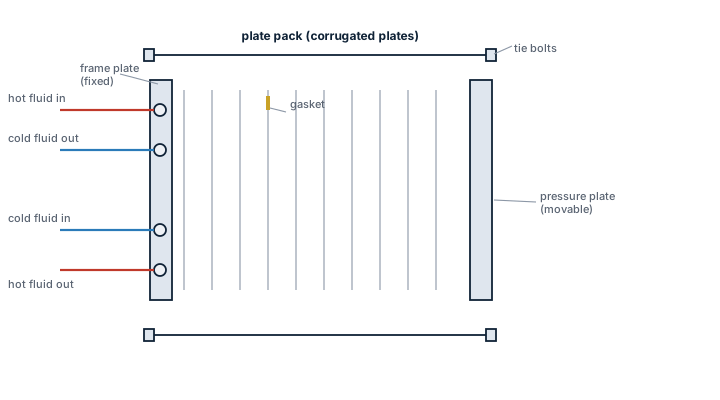
Main components
Plate pack
Pressed stainless steel or titanium plates with a herringbone or chevron corrugation pattern that sets the flow path and turbulence level; plate thickness and corrugation depth are chosen for the pressure and duty.
Gaskets (gasketed type)
Elastomer gaskets, glued or clip-fitted into a groove around each plate, seal the fluid channels and route flow between ports. Gasket material (NBR, EPDM, Viton) is selected for the fluid and temperature; the wrong gasket compound in a fuel or lube oil circuit degrades quickly.
Frame, carrying bar and tightening bolts
The frame clamps the plate pack to a specified compressed thickness; under-tightening lets gaskets leak, over-tightening deforms plates and shortens gasket life.
Brazed or welded pack (compact type)
Copper-brazed or fully welded plate packs eliminate gaskets entirely, giving a smaller, higher-pressure-rated unit that cannot be opened for mechanical cleaning, only backflushed or chemically cleaned.
Selection and sizing
- Duty and approach temperature - the closer the required approach temperature between the two fluids, the more plates or the larger the area needed.
- Pressure rating - gasketed units typically handle up to around 25 bar; brazed and welded types reach substantially higher.
- Fouling tendency of the fluid - seawater cooling duty favours a gasketed, openable design for periodic mechanical cleaning; clean closed-loop duty suits brazed units.
- Materials - titanium plates for raw seawater service resist chloride pitting far better than stainless steel.
- Connection size and plate count - determines physical footprint against available engine room space.
Regulations and class
Plate heat exchangers used in essential services (main engine cooling, fuel heating for combustion) fall under the class society's pressure vessel and piping rules for design pressure, material certification and pressure testing before delivery. Where the exchanger separates a fuel or lube system from a cooling water system, class rules typically require the design to prevent internal cross-contamination or to allow leak detection between circuits, since a failed plate or gasket can let fuel into cooling water or vice versa. There is no IMO convention specific to the plate exchanger type itself; requirements come through the classification society's machinery rules for the system the exchanger is part of.
Typical faults
| Fault | Consequence |
|---|---|
| Gasket hardening or shrinkage with age | inter-plate leakage, cross-contamination between fluid circuits |
| Fouling/scaling in narrow channels | rising pressure drop and falling heat transfer, often mistaken for pump wear |
| Plate corrosion pitting (wrong material for seawater) | through-wall leaks, seawater ingress into the clean circuit |
| Incorrect re-assembly after opening for cleaning | plates out of sequence change the flow path and duty is lost even though the unit looks intact |
What to look for in a supplier
- Material certificates for plates matching the actual fluid, especially titanium confirmation for seawater duty.
- Gasket compound datasheet matching the fluid and maximum operating temperature, not a generic default.
- Availability of individual replacement plates and gaskets for the exact plate pattern, since plate packs are not interchangeable between makers.
Before reassembling a gasketed plate exchanger after cleaning, check the plates go back in the original sequence and orientation - a swapped plate changes the flow pattern and the unit can look assembled correctly while badly underperforming.
38 manufacturers · 1149 models
Alfa Laval
737- Design Pressure M-Line
- >10 bar (145 psi)
- Marine Engine Room Modelle
- T6 (DN60, 800 kW) bis T35 (DN350, 35.000 kW)
- Marine FSRU Modelle
- TS45, T45, T50 (DN450-500, 45.000-55.000 kW)
- Temperaturbereich Standard
- 0–180°C (depending on model)
- FSRU Temperaturbereich
- -50 bis 150°C
- Plattentypen
- Chevron, Gemini Doppelwand, FlexFlow™
- M-Line (High Pressure Series: M3, M6, M10, M15)
- T-Series (Industrial: T2, T5, T6, T8, T10, T20, T25)
- AQ-Series (HVAC: AQ1, AQ2, AQ3, AQ4, AQ10)
- Marine Line (Engine Room: T6-T35; FSRU: TS45, T45, T50)
- Baseline (Competitive Line)
- Hygienic Line (Premium)
- Area: Gasket wear and embrittlementCheck: Inspect seals visually for cracks, hardening, swelling and discoloration; verify material compatibility with process fluids; check ClipGrip™ fastening. Aging symptoms and loss of elasticity are replacement indicators.
- Area: Clamping dimension and tightness (Tightening Dimension A)Check: Verify A-dimension per manufacturer specifications with caliper (metallic contact required). Keep bolts clean and lubricated. Avoid over-tightening. Perform regular re-tightening after operating hours. At too low A-dimension, pressure loss and leakage are to be expected.
- Area: Fouling and scale formation on plate surfacesCheck: Monitor pressure differential across heat exchanger (increase indicates deposits). Check heat duty versus design value. Optimize CIP intervals after performance audits. Deposits generate higher pump load (energy waste up to 8,000 kWh/year possible).
- Area: Plate corrosion and cracks / breakthroughsCheck: After disassembly, inspect plate surfaces for local measurements (pitting), cracks and perforation corrosion. Verify material compatibility with process fluid. Observe fatigue cracks especially at corners and transitions. When perforation occurs, plate is unrecoverable and must be replaced.
- Area: Pressure test and tightness inspectionCheck: After disassembly and cleaning, perform hydrostatic test per data sheet. Test pressure typically 1.5× operating pressure. Check external and internal leakage at all connections and plate edges. Document findings.
- Area: Plate sequence and alignment (5-point alignment)Check: After opening, verify plate sequence and honeycomb pattern (corrected chevron patterns must alternate). Activate/validate 5-point alignment system for larger units. Offset or misplacement leads to short-circuiting and reduced heat duty.
Type-universal inspection points for Alfa Laval Gasketed Plate Heat Exchangers (GPHE) (Alfa Laval, 2026-06). Per-model specs not auto-populated.
- Very high heat‑transfer surface area per unit volume – saves valuable space on board.
- Modular plate stack allows easy capacity changes and quick gasket replacement (5–8 yr interval).
- Wide temperature range (0‑180 °C standard, –50 to 150 °C for FSRU) and pressure rating >10 bar suitable for most marine cooling/heating loops.
- Compatible with fresh water, seawater and low‑oil fluids; multiple plate patterns (Chevron, Gemini, FlexFlow™) optimise performance.
- Gasket wear limits service life compared with welded shell‑and‑tube exchangers; requires regular inspection and torque checks.
- Maximum design pressure (~10 bar) may be insufficient for high‑pressure steam or high‑energy LNG regasification loops.
- Fouling on plate surfaces can increase pressure drop; periodic CIP cleaning is mandatory.
- Corrosion of plates in aggressive seawater environments demands careful material selection and monitoring.
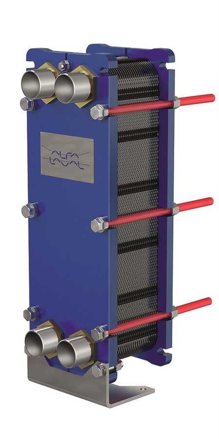
- Design Pressure M-Line
- >10 bar (145 psi)
- Marine Engine Room Modelle
- T6 (DN60, 800 kW) bis T35 (DN350, 35.000 kW)
- Marine FSRU Modelle
- TS45, T45, T50 (DN450-500, 45.000-55.000 kW)
- Temperaturbereich Standard
- 0–180°C (depending on model)
- FSRU Temperaturbereich
- -50 bis 150°C
- Plattentypen
- Chevron, Gemini Doppelwand, FlexFlow™
- M-Line (High Pressure Series: M3, M6, M10, M15)
- T-Series (Industrial: T2, T5, T6, T8, T10, T20, T25)
- AQ-Series (HVAC: AQ1, AQ2, AQ3, AQ4, AQ10)
- Marine Line (Engine Room: T6-T35; FSRU: TS45, T45, T50)
- Baseline (Competitive Line)
- Hygienic Line (Premium)
- Area: Gasket wear and embrittlementCheck: Inspect seals visually for cracks, hardening, swelling and discoloration; verify material compatibility with process fluids; check ClipGrip™ fastening. Aging symptoms and loss of elasticity are replacement indicators.
- Area: Clamping dimension and tightness (Tightening Dimension A)Check: Verify A-dimension per manufacturer specifications with caliper (metallic contact required). Keep bolts clean and lubricated. Avoid over-tightening. Perform regular re-tightening after operating hours. At too low A-dimension, pressure loss and leakage are to be expected.
- Area: Fouling and scale formation on plate surfacesCheck: Monitor pressure differential across heat exchanger (increase indicates deposits). Check heat duty versus design value. Optimize CIP intervals after performance audits. Deposits generate higher pump load (energy waste up to 8,000 kWh/year possible).
- Area: Plate corrosion and cracks / breakthroughsCheck: After disassembly, inspect plate surfaces for local measurements (pitting), cracks and perforation corrosion. Verify material compatibility with process fluid. Observe fatigue cracks especially at corners and transitions. When perforation occurs, plate is unrecoverable and must be replaced.
- Area: Pressure test and tightness inspectionCheck: After disassembly and cleaning, perform hydrostatic test per data sheet. Test pressure typically 1.5× operating pressure. Check external and internal leakage at all connections and plate edges. Document findings.
- Area: Plate sequence and alignment (5-point alignment)Check: After opening, verify plate sequence and honeycomb pattern (corrected chevron patterns must alternate). Activate/validate 5-point alignment system for larger units. Offset or misplacement leads to short-circuiting and reduced heat duty.
Type-universal inspection points for Alfa Laval Gasketed Plate Heat Exchangers (GPHE) (Alfa Laval, 2026-06). Per-model specs not auto-populated.
- Compact footprint ideal for tight engine‑room spaces
- High heat‑transfer efficiency with interchangeable Chevron, Gemini or FlexFlow™ plates
- Design pressure >10 bar suitable for most marine cooling/heating loops
- Modular construction allows easy scaling and maintenance similar to the M10‑MFG series
- Wide operating temperature range (0‑180 °C) covering both heating and cooling duties
- Gasketed design requires regular inspection, tightening and eventual gasket replacement
- Not suited for very high‑pressure applications (>20 bar) or extreme temperatures beyond the rated range
- Susceptible to fouling and scaling if seawater is not adequately pretreated
- Maximum capacity limited by plate count; larger heat loads may need multiple units
- Potential for plate corrosion or cracking when incompatible process fluids are used
- Design Pressure M-Line
- >10 bar (145 psi)
- Marine Engine Room Modelle
- T6 (DN60, 800 kW) bis T35 (DN350, 35.000 kW)
- Marine FSRU Modelle
- TS45, T45, T50 (DN450-500, 45.000-55.000 kW)
- Temperaturbereich Standard
- 0–180°C (depending on model)
- FSRU Temperaturbereich
- -50 bis 150°C
- Plattentypen
- Chevron, Gemini Doppelwand, FlexFlow™
- M-Line (High Pressure Series: M3, M6, M10, M15)
- T-Series (Industrial: T2, T5, T6, T8, T10, T20, T25)
- AQ-Series (HVAC: AQ1, AQ2, AQ3, AQ4, AQ10)
- Marine Line (Engine Room: T6-T35; FSRU: TS45, T45, T50)
- Baseline (Competitive Line)
- Hygienic Line (Premium)
- Area: Gasket wear and embrittlementCheck: Inspect seals visually for cracks, hardening, swelling and discoloration; verify material compatibility with process fluids; check ClipGrip™ fastening. Aging symptoms and loss of elasticity are replacement indicators.
- Area: Clamping dimension and tightness (Tightening Dimension A)Check: Verify A-dimension per manufacturer specifications with caliper (metallic contact required). Keep bolts clean and lubricated. Avoid over-tightening. Perform regular re-tightening after operating hours. At too low A-dimension, pressure loss and leakage are to be expected.
- Area: Fouling and scale formation on plate surfacesCheck: Monitor pressure differential across heat exchanger (increase indicates deposits). Check heat duty versus design value. Optimize CIP intervals after performance audits. Deposits generate higher pump load (energy waste up to 8,000 kWh/year possible).
- Area: Plate corrosion and cracks / breakthroughsCheck: After disassembly, inspect plate surfaces for local measurements (pitting), cracks and perforation corrosion. Verify material compatibility with process fluid. Observe fatigue cracks especially at corners and transitions. When perforation occurs, plate is unrecoverable and must be replaced.
- Area: Pressure test and tightness inspectionCheck: After disassembly and cleaning, perform hydrostatic test per data sheet. Test pressure typically 1.5× operating pressure. Check external and internal leakage at all connections and plate edges. Document findings.
- Area: Plate sequence and alignment (5-point alignment)Check: After opening, verify plate sequence and honeycomb pattern (corrected chevron patterns must alternate). Activate/validate 5-point alignment system for larger units. Offset or misplacement leads to short-circuiting and reduced heat duty.
Type-universal inspection points for Alfa Laval Gasketed Plate Heat Exchangers (GPHE) (Alfa Laval, 2026-06). Per-model specs not auto-populated.

- Design Pressure M-Line
- >10 bar (145 psi)
- Marine Engine Room Modelle
- T6 (DN60, 800 kW) bis T35 (DN350, 35.000 kW)
- Marine FSRU Modelle
- TS45, T45, T50 (DN450-500, 45.000-55.000 kW)
- Temperaturbereich Standard
- 0–180°C (depending on model)
- FSRU Temperaturbereich
- -50 bis 150°C
- Plattentypen
- Chevron, Gemini Doppelwand, FlexFlow™
- M-Line (High Pressure Series: M3, M6, M10, M15)
- T-Series (Industrial: T2, T5, T6, T8, T10, T20, T25)
- AQ-Series (HVAC: AQ1, AQ2, AQ3, AQ4, AQ10)
- Marine Line (Engine Room: T6-T35; FSRU: TS45, T45, T50)
- Baseline (Competitive Line)
- Hygienic Line (Premium)
- Area: Gasket wear and embrittlementCheck: Inspect seals visually for cracks, hardening, swelling and discoloration; verify material compatibility with process fluids; check ClipGrip™ fastening. Aging symptoms and loss of elasticity are replacement indicators.
- Area: Clamping dimension and tightness (Tightening Dimension A)Check: Verify A-dimension per manufacturer specifications with caliper (metallic contact required). Keep bolts clean and lubricated. Avoid over-tightening. Perform regular re-tightening after operating hours. At too low A-dimension, pressure loss and leakage are to be expected.
- Area: Fouling and scale formation on plate surfacesCheck: Monitor pressure differential across heat exchanger (increase indicates deposits). Check heat duty versus design value. Optimize CIP intervals after performance audits. Deposits generate higher pump load (energy waste up to 8,000 kWh/year possible).
- Area: Plate corrosion and cracks / breakthroughsCheck: After disassembly, inspect plate surfaces for local measurements (pitting), cracks and perforation corrosion. Verify material compatibility with process fluid. Observe fatigue cracks especially at corners and transitions. When perforation occurs, plate is unrecoverable and must be replaced.
- Area: Pressure test and tightness inspectionCheck: After disassembly and cleaning, perform hydrostatic test per data sheet. Test pressure typically 1.5× operating pressure. Check external and internal leakage at all connections and plate edges. Document findings.
- Area: Plate sequence and alignment (5-point alignment)Check: After opening, verify plate sequence and honeycomb pattern (corrected chevron patterns must alternate). Activate/validate 5-point alignment system for larger units. Offset or misplacement leads to short-circuiting and reduced heat duty.
Type-universal inspection points for Alfa Laval Gasketed Plate Heat Exchangers (GPHE) (Alfa Laval, 2026-06). Per-model specs not auto-populated.
- Design Pressure M-Line
- >10 bar (145 psi)
- Marine Engine Room Modelle
- T6 (DN60, 800 kW) bis T35 (DN350, 35.000 kW)
- Marine FSRU Modelle
- TS45, T45, T50 (DN450-500, 45.000-55.000 kW)
- Temperaturbereich Standard
- 0–180°C (depending on model)
- FSRU Temperaturbereich
- -50 bis 150°C
- Plattentypen
- Chevron, Gemini Doppelwand, FlexFlow™
- M-Line (High Pressure Series: M3, M6, M10, M15)
- T-Series (Industrial: T2, T5, T6, T8, T10, T20, T25)
- AQ-Series (HVAC: AQ1, AQ2, AQ3, AQ4, AQ10)
- Marine Line (Engine Room: T6-T35; FSRU: TS45, T45, T50)
- Baseline (Competitive Line)
- Hygienic Line (Premium)
- Area: Gasket wear and embrittlementCheck: Inspect seals visually for cracks, hardening, swelling and discoloration; verify material compatibility with process fluids; check ClipGrip™ fastening. Aging symptoms and loss of elasticity are replacement indicators.
- Area: Clamping dimension and tightness (Tightening Dimension A)Check: Verify A-dimension per manufacturer specifications with caliper (metallic contact required). Keep bolts clean and lubricated. Avoid over-tightening. Perform regular re-tightening after operating hours. At too low A-dimension, pressure loss and leakage are to be expected.
- Area: Fouling and scale formation on plate surfacesCheck: Monitor pressure differential across heat exchanger (increase indicates deposits). Check heat duty versus design value. Optimize CIP intervals after performance audits. Deposits generate higher pump load (energy waste up to 8,000 kWh/year possible).
- Area: Plate corrosion and cracks / breakthroughsCheck: After disassembly, inspect plate surfaces for local measurements (pitting), cracks and perforation corrosion. Verify material compatibility with process fluid. Observe fatigue cracks especially at corners and transitions. When perforation occurs, plate is unrecoverable and must be replaced.
- Area: Pressure test and tightness inspectionCheck: After disassembly and cleaning, perform hydrostatic test per data sheet. Test pressure typically 1.5× operating pressure. Check external and internal leakage at all connections and plate edges. Document findings.
- Area: Plate sequence and alignment (5-point alignment)Check: After opening, verify plate sequence and honeycomb pattern (corrected chevron patterns must alternate). Activate/validate 5-point alignment system for larger units. Offset or misplacement leads to short-circuiting and reduced heat duty.
Type-universal inspection points for Alfa Laval Gasketed Plate Heat Exchangers (GPHE) (Alfa Laval, 2026-06). Per-model specs not auto-populated.
- Design Pressure M-Line
- >10 bar (145 psi)
- Marine Engine Room Modelle
- T6 (DN60, 800 kW) bis T35 (DN350, 35.000 kW)
- Marine FSRU Modelle
- TS45, T45, T50 (DN450-500, 45.000-55.000 kW)
- Temperaturbereich Standard
- 0–180°C (depending on model)
- FSRU Temperaturbereich
- -50 bis 150°C
- Plattentypen
- Chevron, Gemini Doppelwand, FlexFlow™
- M-Line (High Pressure Series: M3, M6, M10, M15)
- T-Series (Industrial: T2, T5, T6, T8, T10, T20, T25)
- AQ-Series (HVAC: AQ1, AQ2, AQ3, AQ4, AQ10)
- Marine Line (Engine Room: T6-T35; FSRU: TS45, T45, T50)
- Baseline (Competitive Line)
- Hygienic Line (Premium)
- Area: Gasket wear and embrittlementCheck: Inspect seals visually for cracks, hardening, swelling and discoloration; verify material compatibility with process fluids; check ClipGrip™ fastening. Aging symptoms and loss of elasticity are replacement indicators.
- Area: Clamping dimension and tightness (Tightening Dimension A)Check: Verify A-dimension per manufacturer specifications with caliper (metallic contact required). Keep bolts clean and lubricated. Avoid over-tightening. Perform regular re-tightening after operating hours. At too low A-dimension, pressure loss and leakage are to be expected.
- Area: Fouling and scale formation on plate surfacesCheck: Monitor pressure differential across heat exchanger (increase indicates deposits). Check heat duty versus design value. Optimize CIP intervals after performance audits. Deposits generate higher pump load (energy waste up to 8,000 kWh/year possible).
- Area: Plate corrosion and cracks / breakthroughsCheck: After disassembly, inspect plate surfaces for local measurements (pitting), cracks and perforation corrosion. Verify material compatibility with process fluid. Observe fatigue cracks especially at corners and transitions. When perforation occurs, plate is unrecoverable and must be replaced.
- Area: Pressure test and tightness inspectionCheck: After disassembly and cleaning, perform hydrostatic test per data sheet. Test pressure typically 1.5× operating pressure. Check external and internal leakage at all connections and plate edges. Document findings.
- Area: Plate sequence and alignment (5-point alignment)Check: After opening, verify plate sequence and honeycomb pattern (corrected chevron patterns must alternate). Activate/validate 5-point alignment system for larger units. Offset or misplacement leads to short-circuiting and reduced heat duty.
Type-universal inspection points for Alfa Laval Gasketed Plate Heat Exchangers (GPHE) (Alfa Laval, 2026-06). Per-model specs not auto-populated.
- Design Pressure M-Line
- >10 bar (145 psi)
- Marine Engine Room Modelle
- T6 (DN60, 800 kW) bis T35 (DN350, 35.000 kW)
- Marine FSRU Modelle
- TS45, T45, T50 (DN450-500, 45.000-55.000 kW)
- Temperaturbereich Standard
- 0–180°C (depending on model)
- FSRU Temperaturbereich
- -50 bis 150°C
- Plattentypen
- Chevron, Gemini Doppelwand, FlexFlow™
- M-Line (High Pressure Series: M3, M6, M10, M15)
- T-Series (Industrial: T2, T5, T6, T8, T10, T20, T25)
- AQ-Series (HVAC: AQ1, AQ2, AQ3, AQ4, AQ10)
- Marine Line (Engine Room: T6-T35; FSRU: TS45, T45, T50)
- Baseline (Competitive Line)
- Hygienic Line (Premium)
- Area: Gasket wear and embrittlementCheck: Inspect seals visually for cracks, hardening, swelling and discoloration; verify material compatibility with process fluids; check ClipGrip™ fastening. Aging symptoms and loss of elasticity are replacement indicators.
- Area: Clamping dimension and tightness (Tightening Dimension A)Check: Verify A-dimension per manufacturer specifications with caliper (metallic contact required). Keep bolts clean and lubricated. Avoid over-tightening. Perform regular re-tightening after operating hours. At too low A-dimension, pressure loss and leakage are to be expected.
- Area: Fouling and scale formation on plate surfacesCheck: Monitor pressure differential across heat exchanger (increase indicates deposits). Check heat duty versus design value. Optimize CIP intervals after performance audits. Deposits generate higher pump load (energy waste up to 8,000 kWh/year possible).
- Area: Plate corrosion and cracks / breakthroughsCheck: After disassembly, inspect plate surfaces for local measurements (pitting), cracks and perforation corrosion. Verify material compatibility with process fluid. Observe fatigue cracks especially at corners and transitions. When perforation occurs, plate is unrecoverable and must be replaced.
- Area: Pressure test and tightness inspectionCheck: After disassembly and cleaning, perform hydrostatic test per data sheet. Test pressure typically 1.5× operating pressure. Check external and internal leakage at all connections and plate edges. Document findings.
- Area: Plate sequence and alignment (5-point alignment)Check: After opening, verify plate sequence and honeycomb pattern (corrected chevron patterns must alternate). Activate/validate 5-point alignment system for larger units. Offset or misplacement leads to short-circuiting and reduced heat duty.
Type-universal inspection points for Alfa Laval Gasketed Plate Heat Exchangers (GPHE) (Alfa Laval, 2026-06). Per-model specs not auto-populated.
(t20-semi-welded)(widegap-200)-facing-left.jpg.png)
- Design Pressure M-Line
- >10 bar (145 psi)
- Marine Engine Room Modelle
- T6 (DN60, 800 kW) bis T35 (DN350, 35.000 kW)
- Marine FSRU Modelle
- TS45, T45, T50 (DN450-500, 45.000-55.000 kW)
- Temperaturbereich Standard
- 0–180°C (depending on model)
- FSRU Temperaturbereich
- -50 bis 150°C
- Plattentypen
- Chevron, Gemini Doppelwand, FlexFlow™
- M-Line (High Pressure Series: M3, M6, M10, M15)
- T-Series (Industrial: T2, T5, T6, T8, T10, T20, T25)
- AQ-Series (HVAC: AQ1, AQ2, AQ3, AQ4, AQ10)
- Marine Line (Engine Room: T6-T35; FSRU: TS45, T45, T50)
- Baseline (Competitive Line)
- Hygienic Line (Premium)
- Area: Gasket wear and embrittlementCheck: Inspect seals visually for cracks, hardening, swelling and discoloration; verify material compatibility with process fluids; check ClipGrip™ fastening. Aging symptoms and loss of elasticity are replacement indicators.
- Area: Clamping dimension and tightness (Tightening Dimension A)Check: Verify A-dimension per manufacturer specifications with caliper (metallic contact required). Keep bolts clean and lubricated. Avoid over-tightening. Perform regular re-tightening after operating hours. At too low A-dimension, pressure loss and leakage are to be expected.
- Area: Fouling and scale formation on plate surfacesCheck: Monitor pressure differential across heat exchanger (increase indicates deposits). Check heat duty versus design value. Optimize CIP intervals after performance audits. Deposits generate higher pump load (energy waste up to 8,000 kWh/year possible).
- Area: Plate corrosion and cracks / breakthroughsCheck: After disassembly, inspect plate surfaces for local measurements (pitting), cracks and perforation corrosion. Verify material compatibility with process fluid. Observe fatigue cracks especially at corners and transitions. When perforation occurs, plate is unrecoverable and must be replaced.
- Area: Pressure test and tightness inspectionCheck: After disassembly and cleaning, perform hydrostatic test per data sheet. Test pressure typically 1.5× operating pressure. Check external and internal leakage at all connections and plate edges. Document findings.
- Area: Plate sequence and alignment (5-point alignment)Check: After opening, verify plate sequence and honeycomb pattern (corrected chevron patterns must alternate). Activate/validate 5-point alignment system for larger units. Offset or misplacement leads to short-circuiting and reduced heat duty.
Type-universal inspection points for Alfa Laval Gasketed Plate Heat Exchangers (GPHE) (Alfa Laval, 2026-06). Per-model specs not auto-populated.
- Design Pressure M-Line
- >10 bar (145 psi)
- Marine Engine Room Modelle
- T6 (DN60, 800 kW) bis T35 (DN350, 35.000 kW)
- Marine FSRU Modelle
- TS45, T45, T50 (DN450-500, 45.000-55.000 kW)
- Temperaturbereich Standard
- 0–180°C (depending on model)
- FSRU Temperaturbereich
- -50 bis 150°C
- Plattentypen
- Chevron, Gemini Doppelwand, FlexFlow™
- M-Line (High Pressure Series: M3, M6, M10, M15)
- T-Series (Industrial: T2, T5, T6, T8, T10, T20, T25)
- AQ-Series (HVAC: AQ1, AQ2, AQ3, AQ4, AQ10)
- Marine Line (Engine Room: T6-T35; FSRU: TS45, T45, T50)
- Baseline (Competitive Line)
- Hygienic Line (Premium)
- Area: Gasket wear and embrittlementCheck: Inspect seals visually for cracks, hardening, swelling and discoloration; verify material compatibility with process fluids; check ClipGrip™ fastening. Aging symptoms and loss of elasticity are replacement indicators.
- Area: Clamping dimension and tightness (Tightening Dimension A)Check: Verify A-dimension per manufacturer specifications with caliper (metallic contact required). Keep bolts clean and lubricated. Avoid over-tightening. Perform regular re-tightening after operating hours. At too low A-dimension, pressure loss and leakage are to be expected.
- Area: Fouling and scale formation on plate surfacesCheck: Monitor pressure differential across heat exchanger (increase indicates deposits). Check heat duty versus design value. Optimize CIP intervals after performance audits. Deposits generate higher pump load (energy waste up to 8,000 kWh/year possible).
- Area: Plate corrosion and cracks / breakthroughsCheck: After disassembly, inspect plate surfaces for local measurements (pitting), cracks and perforation corrosion. Verify material compatibility with process fluid. Observe fatigue cracks especially at corners and transitions. When perforation occurs, plate is unrecoverable and must be replaced.
- Area: Pressure test and tightness inspectionCheck: After disassembly and cleaning, perform hydrostatic test per data sheet. Test pressure typically 1.5× operating pressure. Check external and internal leakage at all connections and plate edges. Document findings.
- Area: Plate sequence and alignment (5-point alignment)Check: After opening, verify plate sequence and honeycomb pattern (corrected chevron patterns must alternate). Activate/validate 5-point alignment system for larger units. Offset or misplacement leads to short-circuiting and reduced heat duty.
Type-universal inspection points for Alfa Laval Gasketed Plate Heat Exchangers (GPHE) (Alfa Laval, 2026-06). Per-model specs not auto-populated.
-facing-left_medium.webp)
- Design Pressure M-Line
- >10 bar (145 psi)
- Marine Engine Room Modelle
- T6 (DN60, 800 kW) bis T35 (DN350, 35.000 kW)
- Marine FSRU Modelle
- TS45, T45, T50 (DN450-500, 45.000-55.000 kW)
- Temperaturbereich Standard
- 0–180°C (depending on model)
- FSRU Temperaturbereich
- -50 bis 150°C
- Plattentypen
- Chevron, Gemini Doppelwand, FlexFlow™
- M-Line (High Pressure Series: M3, M6, M10, M15)
- T-Series (Industrial: T2, T5, T6, T8, T10, T20, T25)
- AQ-Series (HVAC: AQ1, AQ2, AQ3, AQ4, AQ10)
- Marine Line (Engine Room: T6-T35; FSRU: TS45, T45, T50)
- Baseline (Competitive Line)
- Hygienic Line (Premium)
- Area: Gasket wear and embrittlementCheck: Inspect seals visually for cracks, hardening, swelling and discoloration; verify material compatibility with process fluids; check ClipGrip™ fastening. Aging symptoms and loss of elasticity are replacement indicators.
- Area: Clamping dimension and tightness (Tightening Dimension A)Check: Verify A-dimension per manufacturer specifications with caliper (metallic contact required). Keep bolts clean and lubricated. Avoid over-tightening. Perform regular re-tightening after operating hours. At too low A-dimension, pressure loss and leakage are to be expected.
- Area: Fouling and scale formation on plate surfacesCheck: Monitor pressure differential across heat exchanger (increase indicates deposits). Check heat duty versus design value. Optimize CIP intervals after performance audits. Deposits generate higher pump load (energy waste up to 8,000 kWh/year possible).
- Area: Plate corrosion and cracks / breakthroughsCheck: After disassembly, inspect plate surfaces for local measurements (pitting), cracks and perforation corrosion. Verify material compatibility with process fluid. Observe fatigue cracks especially at corners and transitions. When perforation occurs, plate is unrecoverable and must be replaced.
- Area: Pressure test and tightness inspectionCheck: After disassembly and cleaning, perform hydrostatic test per data sheet. Test pressure typically 1.5× operating pressure. Check external and internal leakage at all connections and plate edges. Document findings.
- Area: Plate sequence and alignment (5-point alignment)Check: After opening, verify plate sequence and honeycomb pattern (corrected chevron patterns must alternate). Activate/validate 5-point alignment system for larger units. Offset or misplacement leads to short-circuiting and reduced heat duty.
Type-universal inspection points for Alfa Laval Gasketed Plate Heat Exchangers (GPHE) (Alfa Laval, 2026-06). Per-model specs not auto-populated.
- Design Pressure M-Line
- >10 bar (145 psi)
- Marine Engine Room Modelle
- T6 (DN60, 800 kW) bis T35 (DN350, 35.000 kW)
- Marine FSRU Modelle
- TS45, T45, T50 (DN450-500, 45.000-55.000 kW)
- Temperaturbereich Standard
- 0–180°C (depending on model)
- FSRU Temperaturbereich
- -50 bis 150°C
- Plattentypen
- Chevron, Gemini Doppelwand, FlexFlow™
- M-Line (High Pressure Series: M3, M6, M10, M15)
- T-Series (Industrial: T2, T5, T6, T8, T10, T20, T25)
- AQ-Series (HVAC: AQ1, AQ2, AQ3, AQ4, AQ10)
- Marine Line (Engine Room: T6-T35; FSRU: TS45, T45, T50)
- Baseline (Competitive Line)
- Hygienic Line (Premium)
- Area: Gasket wear and embrittlementCheck: Inspect seals visually for cracks, hardening, swelling and discoloration; verify material compatibility with process fluids; check ClipGrip™ fastening. Aging symptoms and loss of elasticity are replacement indicators.
- Area: Clamping dimension and tightness (Tightening Dimension A)Check: Verify A-dimension per manufacturer specifications with caliper (metallic contact required). Keep bolts clean and lubricated. Avoid over-tightening. Perform regular re-tightening after operating hours. At too low A-dimension, pressure loss and leakage are to be expected.
- Area: Fouling and scale formation on plate surfacesCheck: Monitor pressure differential across heat exchanger (increase indicates deposits). Check heat duty versus design value. Optimize CIP intervals after performance audits. Deposits generate higher pump load (energy waste up to 8,000 kWh/year possible).
- Area: Plate corrosion and cracks / breakthroughsCheck: After disassembly, inspect plate surfaces for local measurements (pitting), cracks and perforation corrosion. Verify material compatibility with process fluid. Observe fatigue cracks especially at corners and transitions. When perforation occurs, plate is unrecoverable and must be replaced.
- Area: Pressure test and tightness inspectionCheck: After disassembly and cleaning, perform hydrostatic test per data sheet. Test pressure typically 1.5× operating pressure. Check external and internal leakage at all connections and plate edges. Document findings.
- Area: Plate sequence and alignment (5-point alignment)Check: After opening, verify plate sequence and honeycomb pattern (corrected chevron patterns must alternate). Activate/validate 5-point alignment system for larger units. Offset or misplacement leads to short-circuiting and reduced heat duty.
Type-universal inspection points for Alfa Laval Gasketed Plate Heat Exchangers (GPHE) (Alfa Laval, 2026-06). Per-model specs not auto-populated.
- Design Pressure M-Line
- >10 bar (145 psi)
- Marine Engine Room Modelle
- T6 (DN60, 800 kW) bis T35 (DN350, 35.000 kW)
- Marine FSRU Modelle
- TS45, T45, T50 (DN450-500, 45.000-55.000 kW)
- Temperaturbereich Standard
- 0–180°C (depending on model)
- FSRU Temperaturbereich
- -50 bis 150°C
- Plattentypen
- Chevron, Gemini Doppelwand, FlexFlow™
- M-Line (High Pressure Series: M3, M6, M10, M15)
- T-Series (Industrial: T2, T5, T6, T8, T10, T20, T25)
- AQ-Series (HVAC: AQ1, AQ2, AQ3, AQ4, AQ10)
- Marine Line (Engine Room: T6-T35; FSRU: TS45, T45, T50)
- Baseline (Competitive Line)
- Hygienic Line (Premium)
- Area: Gasket wear and embrittlementCheck: Inspect seals visually for cracks, hardening, swelling and discoloration; verify material compatibility with process fluids; check ClipGrip™ fastening. Aging symptoms and loss of elasticity are replacement indicators.
- Area: Clamping dimension and tightness (Tightening Dimension A)Check: Verify A-dimension per manufacturer specifications with caliper (metallic contact required). Keep bolts clean and lubricated. Avoid over-tightening. Perform regular re-tightening after operating hours. At too low A-dimension, pressure loss and leakage are to be expected.
- Area: Fouling and scale formation on plate surfacesCheck: Monitor pressure differential across heat exchanger (increase indicates deposits). Check heat duty versus design value. Optimize CIP intervals after performance audits. Deposits generate higher pump load (energy waste up to 8,000 kWh/year possible).
- Area: Plate corrosion and cracks / breakthroughsCheck: After disassembly, inspect plate surfaces for local measurements (pitting), cracks and perforation corrosion. Verify material compatibility with process fluid. Observe fatigue cracks especially at corners and transitions. When perforation occurs, plate is unrecoverable and must be replaced.
- Area: Pressure test and tightness inspectionCheck: After disassembly and cleaning, perform hydrostatic test per data sheet. Test pressure typically 1.5× operating pressure. Check external and internal leakage at all connections and plate edges. Document findings.
- Area: Plate sequence and alignment (5-point alignment)Check: After opening, verify plate sequence and honeycomb pattern (corrected chevron patterns must alternate). Activate/validate 5-point alignment system for larger units. Offset or misplacement leads to short-circuiting and reduced heat duty.
Type-universal inspection points for Alfa Laval Gasketed Plate Heat Exchangers (GPHE) (Alfa Laval, 2026-06). Per-model specs not auto-populated.
- Design Pressure M-Line
- >10 bar (145 psi)
- Marine Engine Room Modelle
- T6 (DN60, 800 kW) bis T35 (DN350, 35.000 kW)
- Marine FSRU Modelle
- TS45, T45, T50 (DN450-500, 45.000-55.000 kW)
- Temperaturbereich Standard
- 0–180°C (depending on model)
- FSRU Temperaturbereich
- -50 bis 150°C
- Plattentypen
- Chevron, Gemini Doppelwand, FlexFlow™
- M-Line (High Pressure Series: M3, M6, M10, M15)
- T-Series (Industrial: T2, T5, T6, T8, T10, T20, T25)
- AQ-Series (HVAC: AQ1, AQ2, AQ3, AQ4, AQ10)
- Marine Line (Engine Room: T6-T35; FSRU: TS45, T45, T50)
- Baseline (Competitive Line)
- Hygienic Line (Premium)
- Area: Gasket wear and embrittlementCheck: Inspect seals visually for cracks, hardening, swelling and discoloration; verify material compatibility with process fluids; check ClipGrip™ fastening. Aging symptoms and loss of elasticity are replacement indicators.
- Area: Clamping dimension and tightness (Tightening Dimension A)Check: Verify A-dimension per manufacturer specifications with caliper (metallic contact required). Keep bolts clean and lubricated. Avoid over-tightening. Perform regular re-tightening after operating hours. At too low A-dimension, pressure loss and leakage are to be expected.
- Area: Fouling and scale formation on plate surfacesCheck: Monitor pressure differential across heat exchanger (increase indicates deposits). Check heat duty versus design value. Optimize CIP intervals after performance audits. Deposits generate higher pump load (energy waste up to 8,000 kWh/year possible).
- Area: Plate corrosion and cracks / breakthroughsCheck: After disassembly, inspect plate surfaces for local measurements (pitting), cracks and perforation corrosion. Verify material compatibility with process fluid. Observe fatigue cracks especially at corners and transitions. When perforation occurs, plate is unrecoverable and must be replaced.
- Area: Pressure test and tightness inspectionCheck: After disassembly and cleaning, perform hydrostatic test per data sheet. Test pressure typically 1.5× operating pressure. Check external and internal leakage at all connections and plate edges. Document findings.
- Area: Plate sequence and alignment (5-point alignment)Check: After opening, verify plate sequence and honeycomb pattern (corrected chevron patterns must alternate). Activate/validate 5-point alignment system for larger units. Offset or misplacement leads to short-circuiting and reduced heat duty.
Type-universal inspection points for Alfa Laval Gasketed Plate Heat Exchangers (GPHE) (Alfa Laval, 2026-06). Per-model specs not auto-populated.
- Design Pressure M-Line
- >10 bar (145 psi)
- Marine Engine Room Modelle
- T6 (DN60, 800 kW) bis T35 (DN350, 35.000 kW)
- Marine FSRU Modelle
- TS45, T45, T50 (DN450-500, 45.000-55.000 kW)
- Temperaturbereich Standard
- 0–180°C (depending on model)
- FSRU Temperaturbereich
- -50 bis 150°C
- Plattentypen
- Chevron, Gemini Doppelwand, FlexFlow™
- M-Line (High Pressure Series: M3, M6, M10, M15)
- T-Series (Industrial: T2, T5, T6, T8, T10, T20, T25)
- AQ-Series (HVAC: AQ1, AQ2, AQ3, AQ4, AQ10)
- Marine Line (Engine Room: T6-T35; FSRU: TS45, T45, T50)
- Baseline (Competitive Line)
- Hygienic Line (Premium)
- Area: Gasket wear and embrittlementCheck: Inspect seals visually for cracks, hardening, swelling and discoloration; verify material compatibility with process fluids; check ClipGrip™ fastening. Aging symptoms and loss of elasticity are replacement indicators.
- Area: Clamping dimension and tightness (Tightening Dimension A)Check: Verify A-dimension per manufacturer specifications with caliper (metallic contact required). Keep bolts clean and lubricated. Avoid over-tightening. Perform regular re-tightening after operating hours. At too low A-dimension, pressure loss and leakage are to be expected.
- Area: Fouling and scale formation on plate surfacesCheck: Monitor pressure differential across heat exchanger (increase indicates deposits). Check heat duty versus design value. Optimize CIP intervals after performance audits. Deposits generate higher pump load (energy waste up to 8,000 kWh/year possible).
- Area: Plate corrosion and cracks / breakthroughsCheck: After disassembly, inspect plate surfaces for local measurements (pitting), cracks and perforation corrosion. Verify material compatibility with process fluid. Observe fatigue cracks especially at corners and transitions. When perforation occurs, plate is unrecoverable and must be replaced.
- Area: Pressure test and tightness inspectionCheck: After disassembly and cleaning, perform hydrostatic test per data sheet. Test pressure typically 1.5× operating pressure. Check external and internal leakage at all connections and plate edges. Document findings.
- Area: Plate sequence and alignment (5-point alignment)Check: After opening, verify plate sequence and honeycomb pattern (corrected chevron patterns must alternate). Activate/validate 5-point alignment system for larger units. Offset or misplacement leads to short-circuiting and reduced heat duty.
Type-universal inspection points for Alfa Laval Gasketed Plate Heat Exchangers (GPHE) (Alfa Laval, 2026-06). Per-model specs not auto-populated.
- Design Pressure M-Line
- >10 bar (145 psi)
- Marine Engine Room Modelle
- T6 (DN60, 800 kW) bis T35 (DN350, 35.000 kW)
- Marine FSRU Modelle
- TS45, T45, T50 (DN450-500, 45.000-55.000 kW)
- Temperaturbereich Standard
- 0–180°C (depending on model)
- FSRU Temperaturbereich
- -50 bis 150°C
- Plattentypen
- Chevron, Gemini Doppelwand, FlexFlow™
- M-Line (High Pressure Series: M3, M6, M10, M15)
- T-Series (Industrial: T2, T5, T6, T8, T10, T20, T25)
- AQ-Series (HVAC: AQ1, AQ2, AQ3, AQ4, AQ10)
- Marine Line (Engine Room: T6-T35; FSRU: TS45, T45, T50)
- Baseline (Competitive Line)
- Hygienic Line (Premium)
- Area: Gasket wear and embrittlementCheck: Inspect seals visually for cracks, hardening, swelling and discoloration; verify material compatibility with process fluids; check ClipGrip™ fastening. Aging symptoms and loss of elasticity are replacement indicators.
- Area: Clamping dimension and tightness (Tightening Dimension A)Check: Verify A-dimension per manufacturer specifications with caliper (metallic contact required). Keep bolts clean and lubricated. Avoid over-tightening. Perform regular re-tightening after operating hours. At too low A-dimension, pressure loss and leakage are to be expected.
- Area: Fouling and scale formation on plate surfacesCheck: Monitor pressure differential across heat exchanger (increase indicates deposits). Check heat duty versus design value. Optimize CIP intervals after performance audits. Deposits generate higher pump load (energy waste up to 8,000 kWh/year possible).
- Area: Plate corrosion and cracks / breakthroughsCheck: After disassembly, inspect plate surfaces for local measurements (pitting), cracks and perforation corrosion. Verify material compatibility with process fluid. Observe fatigue cracks especially at corners and transitions. When perforation occurs, plate is unrecoverable and must be replaced.
- Area: Pressure test and tightness inspectionCheck: After disassembly and cleaning, perform hydrostatic test per data sheet. Test pressure typically 1.5× operating pressure. Check external and internal leakage at all connections and plate edges. Document findings.
- Area: Plate sequence and alignment (5-point alignment)Check: After opening, verify plate sequence and honeycomb pattern (corrected chevron patterns must alternate). Activate/validate 5-point alignment system for larger units. Offset or misplacement leads to short-circuiting and reduced heat duty.
Type-universal inspection points for Alfa Laval Gasketed Plate Heat Exchangers (GPHE) (Alfa Laval, 2026-06). Per-model specs not auto-populated.
- Design Pressure M-Line
- >10 bar (145 psi)
- Marine Engine Room Modelle
- T6 (DN60, 800 kW) bis T35 (DN350, 35.000 kW)
- Marine FSRU Modelle
- TS45, T45, T50 (DN450-500, 45.000-55.000 kW)
- Temperaturbereich Standard
- 0–180°C (depending on model)
- FSRU Temperaturbereich
- -50 bis 150°C
- Plattentypen
- Chevron, Gemini Doppelwand, FlexFlow™
- M-Line (High Pressure Series: M3, M6, M10, M15)
- T-Series (Industrial: T2, T5, T6, T8, T10, T20, T25)
- AQ-Series (HVAC: AQ1, AQ2, AQ3, AQ4, AQ10)
- Marine Line (Engine Room: T6-T35; FSRU: TS45, T45, T50)
- Baseline (Competitive Line)
- Hygienic Line (Premium)
- Area: Gasket wear and embrittlementCheck: Inspect seals visually for cracks, hardening, swelling and discoloration; verify material compatibility with process fluids; check ClipGrip™ fastening. Aging symptoms and loss of elasticity are replacement indicators.
- Area: Clamping dimension and tightness (Tightening Dimension A)Check: Verify A-dimension per manufacturer specifications with caliper (metallic contact required). Keep bolts clean and lubricated. Avoid over-tightening. Perform regular re-tightening after operating hours. At too low A-dimension, pressure loss and leakage are to be expected.
- Area: Fouling and scale formation on plate surfacesCheck: Monitor pressure differential across heat exchanger (increase indicates deposits). Check heat duty versus design value. Optimize CIP intervals after performance audits. Deposits generate higher pump load (energy waste up to 8,000 kWh/year possible).
- Area: Plate corrosion and cracks / breakthroughsCheck: After disassembly, inspect plate surfaces for local measurements (pitting), cracks and perforation corrosion. Verify material compatibility with process fluid. Observe fatigue cracks especially at corners and transitions. When perforation occurs, plate is unrecoverable and must be replaced.
- Area: Pressure test and tightness inspectionCheck: After disassembly and cleaning, perform hydrostatic test per data sheet. Test pressure typically 1.5× operating pressure. Check external and internal leakage at all connections and plate edges. Document findings.
- Area: Plate sequence and alignment (5-point alignment)Check: After opening, verify plate sequence and honeycomb pattern (corrected chevron patterns must alternate). Activate/validate 5-point alignment system for larger units. Offset or misplacement leads to short-circuiting and reduced heat duty.
Type-universal inspection points for Alfa Laval Gasketed Plate Heat Exchangers (GPHE) (Alfa Laval, 2026-06). Per-model specs not auto-populated.
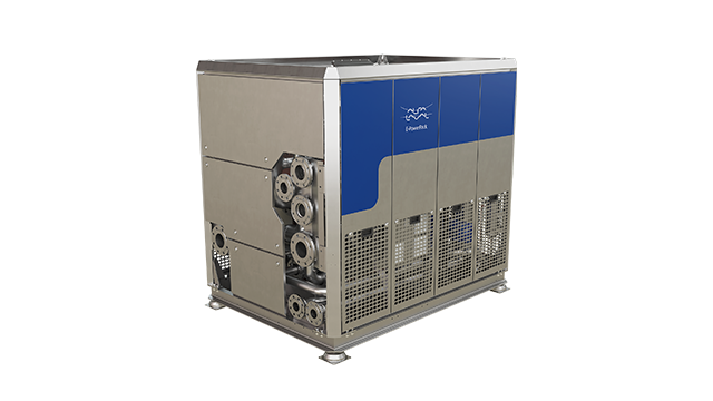
- Design Pressure M-Line
- >10 bar (145 psi)
- Marine Engine Room Modelle
- T6 (DN60, 800 kW) bis T35 (DN350, 35.000 kW)
- Marine FSRU Modelle
- TS45, T45, T50 (DN450-500, 45.000-55.000 kW)
- Temperaturbereich Standard
- 0–180°C (depending on model)
- FSRU Temperaturbereich
- -50 bis 150°C
- Plattentypen
- Chevron, Gemini Doppelwand, FlexFlow™
- M-Line (High Pressure Series: M3, M6, M10, M15)
- T-Series (Industrial: T2, T5, T6, T8, T10, T20, T25)
- AQ-Series (HVAC: AQ1, AQ2, AQ3, AQ4, AQ10)
- Marine Line (Engine Room: T6-T35; FSRU: TS45, T45, T50)
- Baseline (Competitive Line)
- Hygienic Line (Premium)
- Area: Gasket wear and embrittlementCheck: Inspect seals visually for cracks, hardening, swelling and discoloration; verify material compatibility with process fluids; check ClipGrip™ fastening. Aging symptoms and loss of elasticity are replacement indicators.
- Area: Clamping dimension and tightness (Tightening Dimension A)Check: Verify A-dimension per manufacturer specifications with caliper (metallic contact required). Keep bolts clean and lubricated. Avoid over-tightening. Perform regular re-tightening after operating hours. At too low A-dimension, pressure loss and leakage are to be expected.
- Area: Fouling and scale formation on plate surfacesCheck: Monitor pressure differential across heat exchanger (increase indicates deposits). Check heat duty versus design value. Optimize CIP intervals after performance audits. Deposits generate higher pump load (energy waste up to 8,000 kWh/year possible).
- Area: Plate corrosion and cracks / breakthroughsCheck: After disassembly, inspect plate surfaces for local measurements (pitting), cracks and perforation corrosion. Verify material compatibility with process fluid. Observe fatigue cracks especially at corners and transitions. When perforation occurs, plate is unrecoverable and must be replaced.
- Area: Pressure test and tightness inspectionCheck: After disassembly and cleaning, perform hydrostatic test per data sheet. Test pressure typically 1.5× operating pressure. Check external and internal leakage at all connections and plate edges. Document findings.
- Area: Plate sequence and alignment (5-point alignment)Check: After opening, verify plate sequence and honeycomb pattern (corrected chevron patterns must alternate). Activate/validate 5-point alignment system for larger units. Offset or misplacement leads to short-circuiting and reduced heat duty.
Type-universal inspection points for Alfa Laval Gasketed Plate Heat Exchangers (GPHE) (Alfa Laval, 2026-06). Per-model specs not auto-populated.
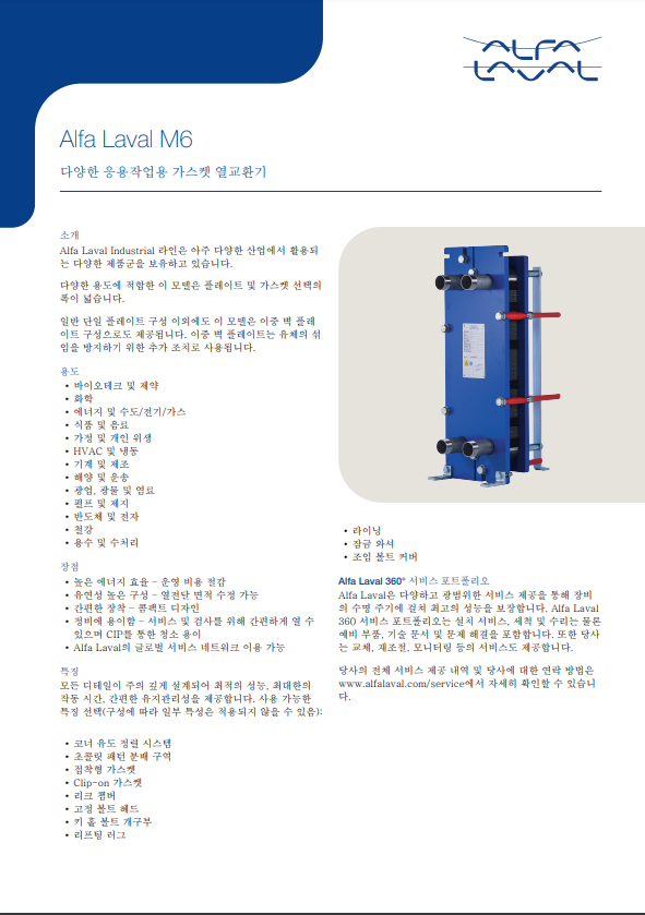
- Design Pressure M-Line
- >10 bar (145 psi)
- Marine Engine Room Modelle
- T6 (DN60, 800 kW) bis T35 (DN350, 35.000 kW)
- Marine FSRU Modelle
- TS45, T45, T50 (DN450-500, 45.000-55.000 kW)
- Temperaturbereich Standard
- 0–180°C (depending on model)
- FSRU Temperaturbereich
- -50 bis 150°C
- Plattentypen
- Chevron, Gemini Doppelwand, FlexFlow™
- M-Line (High Pressure Series: M3, M6, M10, M15)
- T-Series (Industrial: T2, T5, T6, T8, T10, T20, T25)
- AQ-Series (HVAC: AQ1, AQ2, AQ3, AQ4, AQ10)
- Marine Line (Engine Room: T6-T35; FSRU: TS45, T45, T50)
- Baseline (Competitive Line)
- Hygienic Line (Premium)
- Area: Gasket wear and embrittlementCheck: Inspect seals visually for cracks, hardening, swelling and discoloration; verify material compatibility with process fluids; check ClipGrip™ fastening. Aging symptoms and loss of elasticity are replacement indicators.
- Area: Clamping dimension and tightness (Tightening Dimension A)Check: Verify A-dimension per manufacturer specifications with caliper (metallic contact required). Keep bolts clean and lubricated. Avoid over-tightening. Perform regular re-tightening after operating hours. At too low A-dimension, pressure loss and leakage are to be expected.
- Area: Fouling and scale formation on plate surfacesCheck: Monitor pressure differential across heat exchanger (increase indicates deposits). Check heat duty versus design value. Optimize CIP intervals after performance audits. Deposits generate higher pump load (energy waste up to 8,000 kWh/year possible).
- Area: Plate corrosion and cracks / breakthroughsCheck: After disassembly, inspect plate surfaces for local measurements (pitting), cracks and perforation corrosion. Verify material compatibility with process fluid. Observe fatigue cracks especially at corners and transitions. When perforation occurs, plate is unrecoverable and must be replaced.
- Area: Pressure test and tightness inspectionCheck: After disassembly and cleaning, perform hydrostatic test per data sheet. Test pressure typically 1.5× operating pressure. Check external and internal leakage at all connections and plate edges. Document findings.
- Area: Plate sequence and alignment (5-point alignment)Check: After opening, verify plate sequence and honeycomb pattern (corrected chevron patterns must alternate). Activate/validate 5-point alignment system for larger units. Offset or misplacement leads to short-circuiting and reduced heat duty.
Type-universal inspection points for Alfa Laval Gasketed Plate Heat Exchangers (GPHE) (Alfa Laval, 2026-06). Per-model specs not auto-populated.
- Design Pressure M-Line
- >10 bar (145 psi)
- Marine Engine Room Modelle
- T6 (DN60, 800 kW) bis T35 (DN350, 35.000 kW)
- Marine FSRU Modelle
- TS45, T45, T50 (DN450-500, 45.000-55.000 kW)
- Temperaturbereich Standard
- 0–180°C (depending on model)
- FSRU Temperaturbereich
- -50 bis 150°C
- Plattentypen
- Chevron, Gemini Doppelwand, FlexFlow™
- M-Line (High Pressure Series: M3, M6, M10, M15)
- T-Series (Industrial: T2, T5, T6, T8, T10, T20, T25)
- AQ-Series (HVAC: AQ1, AQ2, AQ3, AQ4, AQ10)
- Marine Line (Engine Room: T6-T35; FSRU: TS45, T45, T50)
- Baseline (Competitive Line)
- Hygienic Line (Premium)
- Area: Gasket wear and embrittlementCheck: Inspect seals visually for cracks, hardening, swelling and discoloration; verify material compatibility with process fluids; check ClipGrip™ fastening. Aging symptoms and loss of elasticity are replacement indicators.
- Area: Clamping dimension and tightness (Tightening Dimension A)Check: Verify A-dimension per manufacturer specifications with caliper (metallic contact required). Keep bolts clean and lubricated. Avoid over-tightening. Perform regular re-tightening after operating hours. At too low A-dimension, pressure loss and leakage are to be expected.
- Area: Fouling and scale formation on plate surfacesCheck: Monitor pressure differential across heat exchanger (increase indicates deposits). Check heat duty versus design value. Optimize CIP intervals after performance audits. Deposits generate higher pump load (energy waste up to 8,000 kWh/year possible).
- Area: Plate corrosion and cracks / breakthroughsCheck: After disassembly, inspect plate surfaces for local measurements (pitting), cracks and perforation corrosion. Verify material compatibility with process fluid. Observe fatigue cracks especially at corners and transitions. When perforation occurs, plate is unrecoverable and must be replaced.
- Area: Pressure test and tightness inspectionCheck: After disassembly and cleaning, perform hydrostatic test per data sheet. Test pressure typically 1.5× operating pressure. Check external and internal leakage at all connections and plate edges. Document findings.
- Area: Plate sequence and alignment (5-point alignment)Check: After opening, verify plate sequence and honeycomb pattern (corrected chevron patterns must alternate). Activate/validate 5-point alignment system for larger units. Offset or misplacement leads to short-circuiting and reduced heat duty.
Type-universal inspection points for Alfa Laval Gasketed Plate Heat Exchangers (GPHE) (Alfa Laval, 2026-06). Per-model specs not auto-populated.
- Design Pressure M-Line
- >10 bar (145 psi)
- Marine Engine Room Modelle
- T6 (DN60, 800 kW) bis T35 (DN350, 35.000 kW)
- Marine FSRU Modelle
- TS45, T45, T50 (DN450-500, 45.000-55.000 kW)
- Temperaturbereich Standard
- 0–180°C (depending on model)
- FSRU Temperaturbereich
- -50 bis 150°C
- Plattentypen
- Chevron, Gemini Doppelwand, FlexFlow™
- M-Line (High Pressure Series: M3, M6, M10, M15)
- T-Series (Industrial: T2, T5, T6, T8, T10, T20, T25)
- AQ-Series (HVAC: AQ1, AQ2, AQ3, AQ4, AQ10)
- Marine Line (Engine Room: T6-T35; FSRU: TS45, T45, T50)
- Baseline (Competitive Line)
- Hygienic Line (Premium)
- Area: Gasket wear and embrittlementCheck: Inspect seals visually for cracks, hardening, swelling and discoloration; verify material compatibility with process fluids; check ClipGrip™ fastening. Aging symptoms and loss of elasticity are replacement indicators.
- Area: Clamping dimension and tightness (Tightening Dimension A)Check: Verify A-dimension per manufacturer specifications with caliper (metallic contact required). Keep bolts clean and lubricated. Avoid over-tightening. Perform regular re-tightening after operating hours. At too low A-dimension, pressure loss and leakage are to be expected.
- Area: Fouling and scale formation on plate surfacesCheck: Monitor pressure differential across heat exchanger (increase indicates deposits). Check heat duty versus design value. Optimize CIP intervals after performance audits. Deposits generate higher pump load (energy waste up to 8,000 kWh/year possible).
- Area: Plate corrosion and cracks / breakthroughsCheck: After disassembly, inspect plate surfaces for local measurements (pitting), cracks and perforation corrosion. Verify material compatibility with process fluid. Observe fatigue cracks especially at corners and transitions. When perforation occurs, plate is unrecoverable and must be replaced.
- Area: Pressure test and tightness inspectionCheck: After disassembly and cleaning, perform hydrostatic test per data sheet. Test pressure typically 1.5× operating pressure. Check external and internal leakage at all connections and plate edges. Document findings.
- Area: Plate sequence and alignment (5-point alignment)Check: After opening, verify plate sequence and honeycomb pattern (corrected chevron patterns must alternate). Activate/validate 5-point alignment system for larger units. Offset or misplacement leads to short-circuiting and reduced heat duty.
Type-universal inspection points for Alfa Laval Gasketed Plate Heat Exchangers (GPHE) (Alfa Laval, 2026-06). Per-model specs not auto-populated.
- Design Pressure M-Line
- >10 bar (145 psi)
- Marine Engine Room Modelle
- T6 (DN60, 800 kW) bis T35 (DN350, 35.000 kW)
- Marine FSRU Modelle
- TS45, T45, T50 (DN450-500, 45.000-55.000 kW)
- Temperaturbereich Standard
- 0–180°C (depending on model)
- FSRU Temperaturbereich
- -50 bis 150°C
- Plattentypen
- Chevron, Gemini Doppelwand, FlexFlow™
- M-Line (High Pressure Series: M3, M6, M10, M15)
- T-Series (Industrial: T2, T5, T6, T8, T10, T20, T25)
- AQ-Series (HVAC: AQ1, AQ2, AQ3, AQ4, AQ10)
- Marine Line (Engine Room: T6-T35; FSRU: TS45, T45, T50)
- Baseline (Competitive Line)
- Hygienic Line (Premium)
- Area: Gasket wear and embrittlementCheck: Inspect seals visually for cracks, hardening, swelling and discoloration; verify material compatibility with process fluids; check ClipGrip™ fastening. Aging symptoms and loss of elasticity are replacement indicators.
- Area: Clamping dimension and tightness (Tightening Dimension A)Check: Verify A-dimension per manufacturer specifications with caliper (metallic contact required). Keep bolts clean and lubricated. Avoid over-tightening. Perform regular re-tightening after operating hours. At too low A-dimension, pressure loss and leakage are to be expected.
- Area: Fouling and scale formation on plate surfacesCheck: Monitor pressure differential across heat exchanger (increase indicates deposits). Check heat duty versus design value. Optimize CIP intervals after performance audits. Deposits generate higher pump load (energy waste up to 8,000 kWh/year possible).
- Area: Plate corrosion and cracks / breakthroughsCheck: After disassembly, inspect plate surfaces for local measurements (pitting), cracks and perforation corrosion. Verify material compatibility with process fluid. Observe fatigue cracks especially at corners and transitions. When perforation occurs, plate is unrecoverable and must be replaced.
- Area: Pressure test and tightness inspectionCheck: After disassembly and cleaning, perform hydrostatic test per data sheet. Test pressure typically 1.5× operating pressure. Check external and internal leakage at all connections and plate edges. Document findings.
- Area: Plate sequence and alignment (5-point alignment)Check: After opening, verify plate sequence and honeycomb pattern (corrected chevron patterns must alternate). Activate/validate 5-point alignment system for larger units. Offset or misplacement leads to short-circuiting and reduced heat duty.
Type-universal inspection points for Alfa Laval Gasketed Plate Heat Exchangers (GPHE) (Alfa Laval, 2026-06). Per-model specs not auto-populated.
- Design Pressure M-Line
- >10 bar (145 psi)
- Marine Engine Room Modelle
- T6 (DN60, 800 kW) bis T35 (DN350, 35.000 kW)
- Marine FSRU Modelle
- TS45, T45, T50 (DN450-500, 45.000-55.000 kW)
- Temperaturbereich Standard
- 0–180°C (depending on model)
- FSRU Temperaturbereich
- -50 bis 150°C
- Plattentypen
- Chevron, Gemini Doppelwand, FlexFlow™
- M-Line (High Pressure Series: M3, M6, M10, M15)
- T-Series (Industrial: T2, T5, T6, T8, T10, T20, T25)
- AQ-Series (HVAC: AQ1, AQ2, AQ3, AQ4, AQ10)
- Marine Line (Engine Room: T6-T35; FSRU: TS45, T45, T50)
- Baseline (Competitive Line)
- Hygienic Line (Premium)
- Area: Gasket wear and embrittlementCheck: Inspect seals visually for cracks, hardening, swelling and discoloration; verify material compatibility with process fluids; check ClipGrip™ fastening. Aging symptoms and loss of elasticity are replacement indicators.
- Area: Clamping dimension and tightness (Tightening Dimension A)Check: Verify A-dimension per manufacturer specifications with caliper (metallic contact required). Keep bolts clean and lubricated. Avoid over-tightening. Perform regular re-tightening after operating hours. At too low A-dimension, pressure loss and leakage are to be expected.
- Area: Fouling and scale formation on plate surfacesCheck: Monitor pressure differential across heat exchanger (increase indicates deposits). Check heat duty versus design value. Optimize CIP intervals after performance audits. Deposits generate higher pump load (energy waste up to 8,000 kWh/year possible).
- Area: Plate corrosion and cracks / breakthroughsCheck: After disassembly, inspect plate surfaces for local measurements (pitting), cracks and perforation corrosion. Verify material compatibility with process fluid. Observe fatigue cracks especially at corners and transitions. When perforation occurs, plate is unrecoverable and must be replaced.
- Area: Pressure test and tightness inspectionCheck: After disassembly and cleaning, perform hydrostatic test per data sheet. Test pressure typically 1.5× operating pressure. Check external and internal leakage at all connections and plate edges. Document findings.
- Area: Plate sequence and alignment (5-point alignment)Check: After opening, verify plate sequence and honeycomb pattern (corrected chevron patterns must alternate). Activate/validate 5-point alignment system for larger units. Offset or misplacement leads to short-circuiting and reduced heat duty.
Type-universal inspection points for Alfa Laval Gasketed Plate Heat Exchangers (GPHE) (Alfa Laval, 2026-06). Per-model specs not auto-populated.
- Design Pressure M-Line
- >10 bar (145 psi)
- Marine Engine Room Modelle
- T6 (DN60, 800 kW) bis T35 (DN350, 35.000 kW)
- Marine FSRU Modelle
- TS45, T45, T50 (DN450-500, 45.000-55.000 kW)
- Temperaturbereich Standard
- 0–180°C (depending on model)
- FSRU Temperaturbereich
- -50 bis 150°C
- Plattentypen
- Chevron, Gemini Doppelwand, FlexFlow™
- M-Line (High Pressure Series: M3, M6, M10, M15)
- T-Series (Industrial: T2, T5, T6, T8, T10, T20, T25)
- AQ-Series (HVAC: AQ1, AQ2, AQ3, AQ4, AQ10)
- Marine Line (Engine Room: T6-T35; FSRU: TS45, T45, T50)
- Baseline (Competitive Line)
- Hygienic Line (Premium)
- Area: Gasket wear and embrittlementCheck: Inspect seals visually for cracks, hardening, swelling and discoloration; verify material compatibility with process fluids; check ClipGrip™ fastening. Aging symptoms and loss of elasticity are replacement indicators.
- Area: Clamping dimension and tightness (Tightening Dimension A)Check: Verify A-dimension per manufacturer specifications with caliper (metallic contact required). Keep bolts clean and lubricated. Avoid over-tightening. Perform regular re-tightening after operating hours. At too low A-dimension, pressure loss and leakage are to be expected.
- Area: Fouling and scale formation on plate surfacesCheck: Monitor pressure differential across heat exchanger (increase indicates deposits). Check heat duty versus design value. Optimize CIP intervals after performance audits. Deposits generate higher pump load (energy waste up to 8,000 kWh/year possible).
- Area: Plate corrosion and cracks / breakthroughsCheck: After disassembly, inspect plate surfaces for local measurements (pitting), cracks and perforation corrosion. Verify material compatibility with process fluid. Observe fatigue cracks especially at corners and transitions. When perforation occurs, plate is unrecoverable and must be replaced.
- Area: Pressure test and tightness inspectionCheck: After disassembly and cleaning, perform hydrostatic test per data sheet. Test pressure typically 1.5× operating pressure. Check external and internal leakage at all connections and plate edges. Document findings.
- Area: Plate sequence and alignment (5-point alignment)Check: After opening, verify plate sequence and honeycomb pattern (corrected chevron patterns must alternate). Activate/validate 5-point alignment system for larger units. Offset or misplacement leads to short-circuiting and reduced heat duty.
Type-universal inspection points for Alfa Laval Gasketed Plate Heat Exchangers (GPHE) (Alfa Laval, 2026-06). Per-model specs not auto-populated.
- Design Pressure M-Line
- >10 bar (145 psi)
- Marine Engine Room Modelle
- T6 (DN60, 800 kW) bis T35 (DN350, 35.000 kW)
- Marine FSRU Modelle
- TS45, T45, T50 (DN450-500, 45.000-55.000 kW)
- Temperaturbereich Standard
- 0–180°C (depending on model)
- FSRU Temperaturbereich
- -50 bis 150°C
- Plattentypen
- Chevron, Gemini Doppelwand, FlexFlow™
- M-Line (High Pressure Series: M3, M6, M10, M15)
- T-Series (Industrial: T2, T5, T6, T8, T10, T20, T25)
- AQ-Series (HVAC: AQ1, AQ2, AQ3, AQ4, AQ10)
- Marine Line (Engine Room: T6-T35; FSRU: TS45, T45, T50)
- Baseline (Competitive Line)
- Hygienic Line (Premium)
- Area: Gasket wear and embrittlementCheck: Inspect seals visually for cracks, hardening, swelling and discoloration; verify material compatibility with process fluids; check ClipGrip™ fastening. Aging symptoms and loss of elasticity are replacement indicators.
- Area: Clamping dimension and tightness (Tightening Dimension A)Check: Verify A-dimension per manufacturer specifications with caliper (metallic contact required). Keep bolts clean and lubricated. Avoid over-tightening. Perform regular re-tightening after operating hours. At too low A-dimension, pressure loss and leakage are to be expected.
- Area: Fouling and scale formation on plate surfacesCheck: Monitor pressure differential across heat exchanger (increase indicates deposits). Check heat duty versus design value. Optimize CIP intervals after performance audits. Deposits generate higher pump load (energy waste up to 8,000 kWh/year possible).
- Area: Plate corrosion and cracks / breakthroughsCheck: After disassembly, inspect plate surfaces for local measurements (pitting), cracks and perforation corrosion. Verify material compatibility with process fluid. Observe fatigue cracks especially at corners and transitions. When perforation occurs, plate is unrecoverable and must be replaced.
- Area: Pressure test and tightness inspectionCheck: After disassembly and cleaning, perform hydrostatic test per data sheet. Test pressure typically 1.5× operating pressure. Check external and internal leakage at all connections and plate edges. Document findings.
- Area: Plate sequence and alignment (5-point alignment)Check: After opening, verify plate sequence and honeycomb pattern (corrected chevron patterns must alternate). Activate/validate 5-point alignment system for larger units. Offset or misplacement leads to short-circuiting and reduced heat duty.
Type-universal inspection points for Alfa Laval Gasketed Plate Heat Exchangers (GPHE) (Alfa Laval, 2026-06). Per-model specs not auto-populated.
- Design Pressure M-Line
- >10 bar (145 psi)
- Marine Engine Room Modelle
- T6 (DN60, 800 kW) bis T35 (DN350, 35.000 kW)
- Marine FSRU Modelle
- TS45, T45, T50 (DN450-500, 45.000-55.000 kW)
- Temperaturbereich Standard
- 0–180°C (depending on model)
- FSRU Temperaturbereich
- -50 bis 150°C
- Plattentypen
- Chevron, Gemini Doppelwand, FlexFlow™
- M-Line (High Pressure Series: M3, M6, M10, M15)
- T-Series (Industrial: T2, T5, T6, T8, T10, T20, T25)
- AQ-Series (HVAC: AQ1, AQ2, AQ3, AQ4, AQ10)
- Marine Line (Engine Room: T6-T35; FSRU: TS45, T45, T50)
- Baseline (Competitive Line)
- Hygienic Line (Premium)
- Area: Gasket wear and embrittlementCheck: Inspect seals visually for cracks, hardening, swelling and discoloration; verify material compatibility with process fluids; check ClipGrip™ fastening. Aging symptoms and loss of elasticity are replacement indicators.
- Area: Clamping dimension and tightness (Tightening Dimension A)Check: Verify A-dimension per manufacturer specifications with caliper (metallic contact required). Keep bolts clean and lubricated. Avoid over-tightening. Perform regular re-tightening after operating hours. At too low A-dimension, pressure loss and leakage are to be expected.
- Area: Fouling and scale formation on plate surfacesCheck: Monitor pressure differential across heat exchanger (increase indicates deposits). Check heat duty versus design value. Optimize CIP intervals after performance audits. Deposits generate higher pump load (energy waste up to 8,000 kWh/year possible).
- Area: Plate corrosion and cracks / breakthroughsCheck: After disassembly, inspect plate surfaces for local measurements (pitting), cracks and perforation corrosion. Verify material compatibility with process fluid. Observe fatigue cracks especially at corners and transitions. When perforation occurs, plate is unrecoverable and must be replaced.
- Area: Pressure test and tightness inspectionCheck: After disassembly and cleaning, perform hydrostatic test per data sheet. Test pressure typically 1.5× operating pressure. Check external and internal leakage at all connections and plate edges. Document findings.
- Area: Plate sequence and alignment (5-point alignment)Check: After opening, verify plate sequence and honeycomb pattern (corrected chevron patterns must alternate). Activate/validate 5-point alignment system for larger units. Offset or misplacement leads to short-circuiting and reduced heat duty.
Type-universal inspection points for Alfa Laval Gasketed Plate Heat Exchangers (GPHE) (Alfa Laval, 2026-06). Per-model specs not auto-populated.

- Design Pressure M-Line
- >10 bar (145 psi)
- Marine Engine Room Modelle
- T6 (DN60, 800 kW) bis T35 (DN350, 35.000 kW)
- Marine FSRU Modelle
- TS45, T45, T50 (DN450-500, 45.000-55.000 kW)
- Temperaturbereich Standard
- 0–180°C (depending on model)
- FSRU Temperaturbereich
- -50 bis 150°C
- Plattentypen
- Chevron, Gemini Doppelwand, FlexFlow™
- M-Line (High Pressure Series: M3, M6, M10, M15)
- T-Series (Industrial: T2, T5, T6, T8, T10, T20, T25)
- AQ-Series (HVAC: AQ1, AQ2, AQ3, AQ4, AQ10)
- Marine Line (Engine Room: T6-T35; FSRU: TS45, T45, T50)
- Baseline (Competitive Line)
- Hygienic Line (Premium)
- Area: Gasket wear and embrittlementCheck: Inspect seals visually for cracks, hardening, swelling and discoloration; verify material compatibility with process fluids; check ClipGrip™ fastening. Aging symptoms and loss of elasticity are replacement indicators.
- Area: Clamping dimension and tightness (Tightening Dimension A)Check: Verify A-dimension per manufacturer specifications with caliper (metallic contact required). Keep bolts clean and lubricated. Avoid over-tightening. Perform regular re-tightening after operating hours. At too low A-dimension, pressure loss and leakage are to be expected.
- Area: Fouling and scale formation on plate surfacesCheck: Monitor pressure differential across heat exchanger (increase indicates deposits). Check heat duty versus design value. Optimize CIP intervals after performance audits. Deposits generate higher pump load (energy waste up to 8,000 kWh/year possible).
- Area: Plate corrosion and cracks / breakthroughsCheck: After disassembly, inspect plate surfaces for local measurements (pitting), cracks and perforation corrosion. Verify material compatibility with process fluid. Observe fatigue cracks especially at corners and transitions. When perforation occurs, plate is unrecoverable and must be replaced.
- Area: Pressure test and tightness inspectionCheck: After disassembly and cleaning, perform hydrostatic test per data sheet. Test pressure typically 1.5× operating pressure. Check external and internal leakage at all connections and plate edges. Document findings.
- Area: Plate sequence and alignment (5-point alignment)Check: After opening, verify plate sequence and honeycomb pattern (corrected chevron patterns must alternate). Activate/validate 5-point alignment system for larger units. Offset or misplacement leads to short-circuiting and reduced heat duty.
Type-universal inspection points for Alfa Laval Gasketed Plate Heat Exchangers (GPHE) (Alfa Laval, 2026-06). Per-model specs not auto-populated.
- Design Pressure M-Line
- >10 bar (145 psi)
- Marine Engine Room Modelle
- T6 (DN60, 800 kW) bis T35 (DN350, 35.000 kW)
- Marine FSRU Modelle
- TS45, T45, T50 (DN450-500, 45.000-55.000 kW)
- Temperaturbereich Standard
- 0–180°C (depending on model)
- FSRU Temperaturbereich
- -50 bis 150°C
- Plattentypen
- Chevron, Gemini Doppelwand, FlexFlow™
- M-Line (High Pressure Series: M3, M6, M10, M15)
- T-Series (Industrial: T2, T5, T6, T8, T10, T20, T25)
- AQ-Series (HVAC: AQ1, AQ2, AQ3, AQ4, AQ10)
- Marine Line (Engine Room: T6-T35; FSRU: TS45, T45, T50)
- Baseline (Competitive Line)
- Hygienic Line (Premium)
- Area: Gasket wear and embrittlementCheck: Inspect seals visually for cracks, hardening, swelling and discoloration; verify material compatibility with process fluids; check ClipGrip™ fastening. Aging symptoms and loss of elasticity are replacement indicators.
- Area: Clamping dimension and tightness (Tightening Dimension A)Check: Verify A-dimension per manufacturer specifications with caliper (metallic contact required). Keep bolts clean and lubricated. Avoid over-tightening. Perform regular re-tightening after operating hours. At too low A-dimension, pressure loss and leakage are to be expected.
- Area: Fouling and scale formation on plate surfacesCheck: Monitor pressure differential across heat exchanger (increase indicates deposits). Check heat duty versus design value. Optimize CIP intervals after performance audits. Deposits generate higher pump load (energy waste up to 8,000 kWh/year possible).
- Area: Plate corrosion and cracks / breakthroughsCheck: After disassembly, inspect plate surfaces for local measurements (pitting), cracks and perforation corrosion. Verify material compatibility with process fluid. Observe fatigue cracks especially at corners and transitions. When perforation occurs, plate is unrecoverable and must be replaced.
- Area: Pressure test and tightness inspectionCheck: After disassembly and cleaning, perform hydrostatic test per data sheet. Test pressure typically 1.5× operating pressure. Check external and internal leakage at all connections and plate edges. Document findings.
- Area: Plate sequence and alignment (5-point alignment)Check: After opening, verify plate sequence and honeycomb pattern (corrected chevron patterns must alternate). Activate/validate 5-point alignment system for larger units. Offset or misplacement leads to short-circuiting and reduced heat duty.
Type-universal inspection points for Alfa Laval Gasketed Plate Heat Exchangers (GPHE) (Alfa Laval, 2026-06). Per-model specs not auto-populated.
- Design Pressure M-Line
- >10 bar (145 psi)
- Marine Engine Room Modelle
- T6 (DN60, 800 kW) bis T35 (DN350, 35.000 kW)
- Marine FSRU Modelle
- TS45, T45, T50 (DN450-500, 45.000-55.000 kW)
- Temperaturbereich Standard
- 0–180°C (depending on model)
- FSRU Temperaturbereich
- -50 bis 150°C
- Plattentypen
- Chevron, Gemini Doppelwand, FlexFlow™
- M-Line (High Pressure Series: M3, M6, M10, M15)
- T-Series (Industrial: T2, T5, T6, T8, T10, T20, T25)
- AQ-Series (HVAC: AQ1, AQ2, AQ3, AQ4, AQ10)
- Marine Line (Engine Room: T6-T35; FSRU: TS45, T45, T50)
- Baseline (Competitive Line)
- Hygienic Line (Premium)
- Area: Gasket wear and embrittlementCheck: Inspect seals visually for cracks, hardening, swelling and discoloration; verify material compatibility with process fluids; check ClipGrip™ fastening. Aging symptoms and loss of elasticity are replacement indicators.
- Area: Clamping dimension and tightness (Tightening Dimension A)Check: Verify A-dimension per manufacturer specifications with caliper (metallic contact required). Keep bolts clean and lubricated. Avoid over-tightening. Perform regular re-tightening after operating hours. At too low A-dimension, pressure loss and leakage are to be expected.
- Area: Fouling and scale formation on plate surfacesCheck: Monitor pressure differential across heat exchanger (increase indicates deposits). Check heat duty versus design value. Optimize CIP intervals after performance audits. Deposits generate higher pump load (energy waste up to 8,000 kWh/year possible).
- Area: Plate corrosion and cracks / breakthroughsCheck: After disassembly, inspect plate surfaces for local measurements (pitting), cracks and perforation corrosion. Verify material compatibility with process fluid. Observe fatigue cracks especially at corners and transitions. When perforation occurs, plate is unrecoverable and must be replaced.
- Area: Pressure test and tightness inspectionCheck: After disassembly and cleaning, perform hydrostatic test per data sheet. Test pressure typically 1.5× operating pressure. Check external and internal leakage at all connections and plate edges. Document findings.
- Area: Plate sequence and alignment (5-point alignment)Check: After opening, verify plate sequence and honeycomb pattern (corrected chevron patterns must alternate). Activate/validate 5-point alignment system for larger units. Offset or misplacement leads to short-circuiting and reduced heat duty.
Type-universal inspection points for Alfa Laval Gasketed Plate Heat Exchangers (GPHE) (Alfa Laval, 2026-06). Per-model specs not auto-populated.
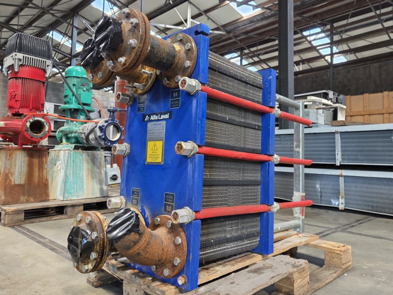
- Design Pressure M-Line
- >10 bar (145 psi)
- Marine Engine Room Modelle
- T6 (DN60, 800 kW) bis T35 (DN350, 35.000 kW)
- Marine FSRU Modelle
- TS45, T45, T50 (DN450-500, 45.000-55.000 kW)
- Temperaturbereich Standard
- 0–180°C (depending on model)
- FSRU Temperaturbereich
- -50 bis 150°C
- Plattentypen
- Chevron, Gemini Doppelwand, FlexFlow™
- M-Line (High Pressure Series: M3, M6, M10, M15)
- T-Series (Industrial: T2, T5, T6, T8, T10, T20, T25)
- AQ-Series (HVAC: AQ1, AQ2, AQ3, AQ4, AQ10)
- Marine Line (Engine Room: T6-T35; FSRU: TS45, T45, T50)
- Baseline (Competitive Line)
- Hygienic Line (Premium)
- Area: Gasket wear and embrittlementCheck: Inspect seals visually for cracks, hardening, swelling and discoloration; verify material compatibility with process fluids; check ClipGrip™ fastening. Aging symptoms and loss of elasticity are replacement indicators.
- Area: Clamping dimension and tightness (Tightening Dimension A)Check: Verify A-dimension per manufacturer specifications with caliper (metallic contact required). Keep bolts clean and lubricated. Avoid over-tightening. Perform regular re-tightening after operating hours. At too low A-dimension, pressure loss and leakage are to be expected.
- Area: Fouling and scale formation on plate surfacesCheck: Monitor pressure differential across heat exchanger (increase indicates deposits). Check heat duty versus design value. Optimize CIP intervals after performance audits. Deposits generate higher pump load (energy waste up to 8,000 kWh/year possible).
- Area: Plate corrosion and cracks / breakthroughsCheck: After disassembly, inspect plate surfaces for local measurements (pitting), cracks and perforation corrosion. Verify material compatibility with process fluid. Observe fatigue cracks especially at corners and transitions. When perforation occurs, plate is unrecoverable and must be replaced.
- Area: Pressure test and tightness inspectionCheck: After disassembly and cleaning, perform hydrostatic test per data sheet. Test pressure typically 1.5× operating pressure. Check external and internal leakage at all connections and plate edges. Document findings.
- Area: Plate sequence and alignment (5-point alignment)Check: After opening, verify plate sequence and honeycomb pattern (corrected chevron patterns must alternate). Activate/validate 5-point alignment system for larger units. Offset or misplacement leads to short-circuiting and reduced heat duty.
Type-universal inspection points for Alfa Laval Gasketed Plate Heat Exchangers (GPHE) (Alfa Laval, 2026-06). Per-model specs not auto-populated.

- Design Pressure M-Line
- >10 bar (145 psi)
- Marine Engine Room Modelle
- T6 (DN60, 800 kW) bis T35 (DN350, 35.000 kW)
- Marine FSRU Modelle
- TS45, T45, T50 (DN450-500, 45.000-55.000 kW)
- Temperaturbereich Standard
- 0–180°C (depending on model)
- FSRU Temperaturbereich
- -50 bis 150°C
- Plattentypen
- Chevron, Gemini Doppelwand, FlexFlow™
- M-Line (High Pressure Series: M3, M6, M10, M15)
- T-Series (Industrial: T2, T5, T6, T8, T10, T20, T25)
- AQ-Series (HVAC: AQ1, AQ2, AQ3, AQ4, AQ10)
- Marine Line (Engine Room: T6-T35; FSRU: TS45, T45, T50)
- Baseline (Competitive Line)
- Hygienic Line (Premium)
- Area: Gasket wear and embrittlementCheck: Inspect seals visually for cracks, hardening, swelling and discoloration; verify material compatibility with process fluids; check ClipGrip™ fastening. Aging symptoms and loss of elasticity are replacement indicators.
- Area: Clamping dimension and tightness (Tightening Dimension A)Check: Verify A-dimension per manufacturer specifications with caliper (metallic contact required). Keep bolts clean and lubricated. Avoid over-tightening. Perform regular re-tightening after operating hours. At too low A-dimension, pressure loss and leakage are to be expected.
- Area: Fouling and scale formation on plate surfacesCheck: Monitor pressure differential across heat exchanger (increase indicates deposits). Check heat duty versus design value. Optimize CIP intervals after performance audits. Deposits generate higher pump load (energy waste up to 8,000 kWh/year possible).
- Area: Plate corrosion and cracks / breakthroughsCheck: After disassembly, inspect plate surfaces for local measurements (pitting), cracks and perforation corrosion. Verify material compatibility with process fluid. Observe fatigue cracks especially at corners and transitions. When perforation occurs, plate is unrecoverable and must be replaced.
- Area: Pressure test and tightness inspectionCheck: After disassembly and cleaning, perform hydrostatic test per data sheet. Test pressure typically 1.5× operating pressure. Check external and internal leakage at all connections and plate edges. Document findings.
- Area: Plate sequence and alignment (5-point alignment)Check: After opening, verify plate sequence and honeycomb pattern (corrected chevron patterns must alternate). Activate/validate 5-point alignment system for larger units. Offset or misplacement leads to short-circuiting and reduced heat duty.
Type-universal inspection points for Alfa Laval Gasketed Plate Heat Exchangers (GPHE) (Alfa Laval, 2026-06). Per-model specs not auto-populated.
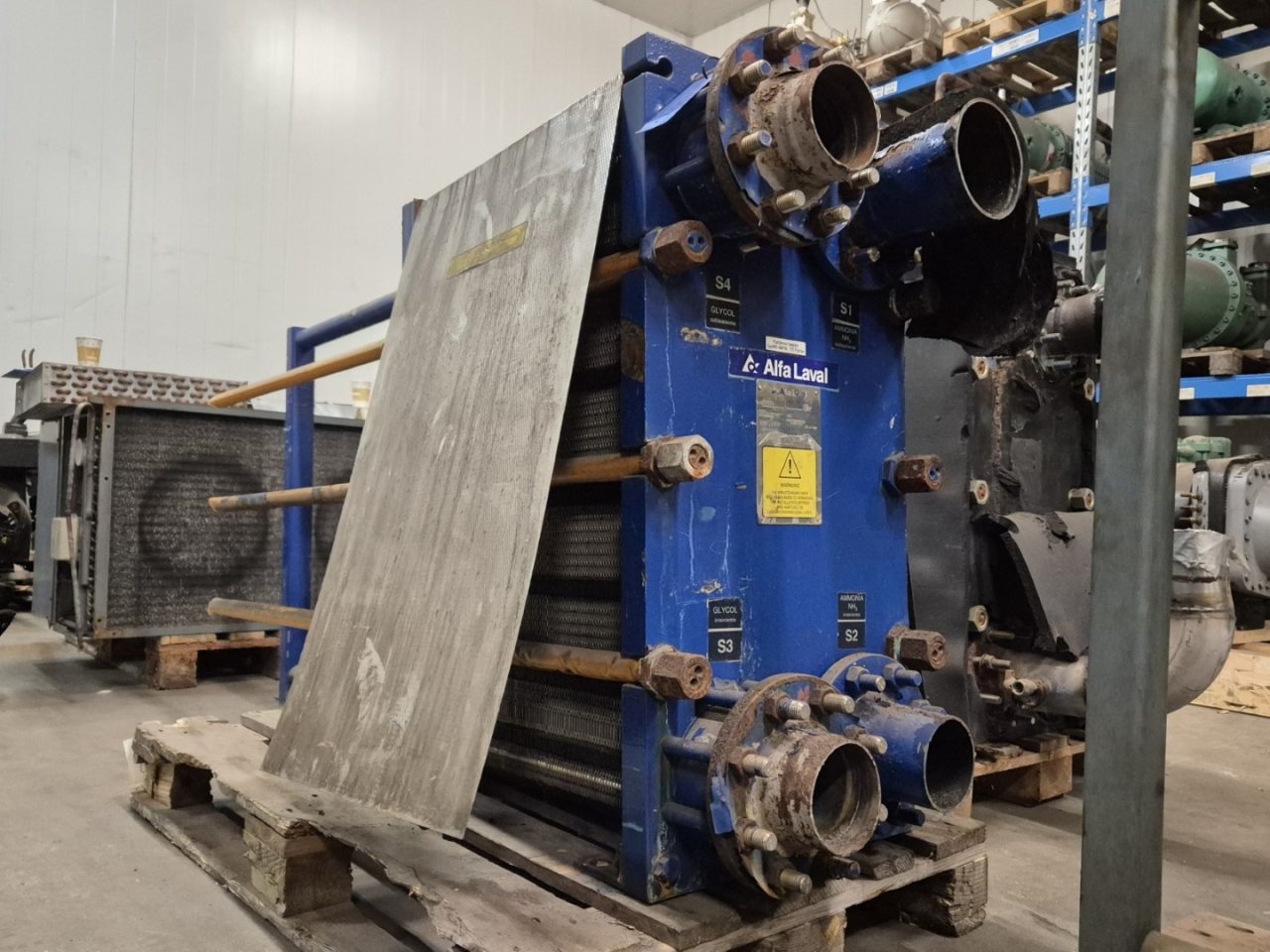
- Design Pressure M-Line
- >10 bar (145 psi)
- Marine Engine Room Modelle
- T6 (DN60, 800 kW) bis T35 (DN350, 35.000 kW)
- Marine FSRU Modelle
- TS45, T45, T50 (DN450-500, 45.000-55.000 kW)
- Temperaturbereich Standard
- 0–180°C (depending on model)
- FSRU Temperaturbereich
- -50 bis 150°C
- Plattentypen
- Chevron, Gemini Doppelwand, FlexFlow™
- M-Line (High Pressure Series: M3, M6, M10, M15)
- T-Series (Industrial: T2, T5, T6, T8, T10, T20, T25)
- AQ-Series (HVAC: AQ1, AQ2, AQ3, AQ4, AQ10)
- Marine Line (Engine Room: T6-T35; FSRU: TS45, T45, T50)
- Baseline (Competitive Line)
- Hygienic Line (Premium)
- Area: Gasket wear and embrittlementCheck: Inspect seals visually for cracks, hardening, swelling and discoloration; verify material compatibility with process fluids; check ClipGrip™ fastening. Aging symptoms and loss of elasticity are replacement indicators.
- Area: Clamping dimension and tightness (Tightening Dimension A)Check: Verify A-dimension per manufacturer specifications with caliper (metallic contact required). Keep bolts clean and lubricated. Avoid over-tightening. Perform regular re-tightening after operating hours. At too low A-dimension, pressure loss and leakage are to be expected.
- Area: Fouling and scale formation on plate surfacesCheck: Monitor pressure differential across heat exchanger (increase indicates deposits). Check heat duty versus design value. Optimize CIP intervals after performance audits. Deposits generate higher pump load (energy waste up to 8,000 kWh/year possible).
- Area: Plate corrosion and cracks / breakthroughsCheck: After disassembly, inspect plate surfaces for local measurements (pitting), cracks and perforation corrosion. Verify material compatibility with process fluid. Observe fatigue cracks especially at corners and transitions. When perforation occurs, plate is unrecoverable and must be replaced.
- Area: Pressure test and tightness inspectionCheck: After disassembly and cleaning, perform hydrostatic test per data sheet. Test pressure typically 1.5× operating pressure. Check external and internal leakage at all connections and plate edges. Document findings.
- Area: Plate sequence and alignment (5-point alignment)Check: After opening, verify plate sequence and honeycomb pattern (corrected chevron patterns must alternate). Activate/validate 5-point alignment system for larger units. Offset or misplacement leads to short-circuiting and reduced heat duty.
Type-universal inspection points for Alfa Laval Gasketed Plate Heat Exchangers (GPHE) (Alfa Laval, 2026-06). Per-model specs not auto-populated.
- Design Pressure M-Line
- >10 bar (145 psi)
- Marine Engine Room Modelle
- T6 (DN60, 800 kW) bis T35 (DN350, 35.000 kW)
- Marine FSRU Modelle
- TS45, T45, T50 (DN450-500, 45.000-55.000 kW)
- Temperaturbereich Standard
- 0–180°C (depending on model)
- FSRU Temperaturbereich
- -50 bis 150°C
- Plattentypen
- Chevron, Gemini Doppelwand, FlexFlow™
- M-Line (High Pressure Series: M3, M6, M10, M15)
- T-Series (Industrial: T2, T5, T6, T8, T10, T20, T25)
- AQ-Series (HVAC: AQ1, AQ2, AQ3, AQ4, AQ10)
- Marine Line (Engine Room: T6-T35; FSRU: TS45, T45, T50)
- Baseline (Competitive Line)
- Hygienic Line (Premium)
- Area: Gasket wear and embrittlementCheck: Inspect seals visually for cracks, hardening, swelling and discoloration; verify material compatibility with process fluids; check ClipGrip™ fastening. Aging symptoms and loss of elasticity are replacement indicators.
- Area: Clamping dimension and tightness (Tightening Dimension A)Check: Verify A-dimension per manufacturer specifications with caliper (metallic contact required). Keep bolts clean and lubricated. Avoid over-tightening. Perform regular re-tightening after operating hours. At too low A-dimension, pressure loss and leakage are to be expected.
- Area: Fouling and scale formation on plate surfacesCheck: Monitor pressure differential across heat exchanger (increase indicates deposits). Check heat duty versus design value. Optimize CIP intervals after performance audits. Deposits generate higher pump load (energy waste up to 8,000 kWh/year possible).
- Area: Plate corrosion and cracks / breakthroughsCheck: After disassembly, inspect plate surfaces for local measurements (pitting), cracks and perforation corrosion. Verify material compatibility with process fluid. Observe fatigue cracks especially at corners and transitions. When perforation occurs, plate is unrecoverable and must be replaced.
- Area: Pressure test and tightness inspectionCheck: After disassembly and cleaning, perform hydrostatic test per data sheet. Test pressure typically 1.5× operating pressure. Check external and internal leakage at all connections and plate edges. Document findings.
- Area: Plate sequence and alignment (5-point alignment)Check: After opening, verify plate sequence and honeycomb pattern (corrected chevron patterns must alternate). Activate/validate 5-point alignment system for larger units. Offset or misplacement leads to short-circuiting and reduced heat duty.
Type-universal inspection points for Alfa Laval Gasketed Plate Heat Exchangers (GPHE) (Alfa Laval, 2026-06). Per-model specs not auto-populated.
- Design Pressure M-Line
- >10 bar (145 psi)
- Marine Engine Room Modelle
- T6 (DN60, 800 kW) bis T35 (DN350, 35.000 kW)
- Marine FSRU Modelle
- TS45, T45, T50 (DN450-500, 45.000-55.000 kW)
- Temperaturbereich Standard
- 0–180°C (depending on model)
- FSRU Temperaturbereich
- -50 bis 150°C
- Plattentypen
- Chevron, Gemini Doppelwand, FlexFlow™
- M-Line (High Pressure Series: M3, M6, M10, M15)
- T-Series (Industrial: T2, T5, T6, T8, T10, T20, T25)
- AQ-Series (HVAC: AQ1, AQ2, AQ3, AQ4, AQ10)
- Marine Line (Engine Room: T6-T35; FSRU: TS45, T45, T50)
- Baseline (Competitive Line)
- Hygienic Line (Premium)
- Area: Gasket wear and embrittlementCheck: Inspect seals visually for cracks, hardening, swelling and discoloration; verify material compatibility with process fluids; check ClipGrip™ fastening. Aging symptoms and loss of elasticity are replacement indicators.
- Area: Clamping dimension and tightness (Tightening Dimension A)Check: Verify A-dimension per manufacturer specifications with caliper (metallic contact required). Keep bolts clean and lubricated. Avoid over-tightening. Perform regular re-tightening after operating hours. At too low A-dimension, pressure loss and leakage are to be expected.
- Area: Fouling and scale formation on plate surfacesCheck: Monitor pressure differential across heat exchanger (increase indicates deposits). Check heat duty versus design value. Optimize CIP intervals after performance audits. Deposits generate higher pump load (energy waste up to 8,000 kWh/year possible).
- Area: Plate corrosion and cracks / breakthroughsCheck: After disassembly, inspect plate surfaces for local measurements (pitting), cracks and perforation corrosion. Verify material compatibility with process fluid. Observe fatigue cracks especially at corners and transitions. When perforation occurs, plate is unrecoverable and must be replaced.
- Area: Pressure test and tightness inspectionCheck: After disassembly and cleaning, perform hydrostatic test per data sheet. Test pressure typically 1.5× operating pressure. Check external and internal leakage at all connections and plate edges. Document findings.
- Area: Plate sequence and alignment (5-point alignment)Check: After opening, verify plate sequence and honeycomb pattern (corrected chevron patterns must alternate). Activate/validate 5-point alignment system for larger units. Offset or misplacement leads to short-circuiting and reduced heat duty.
Type-universal inspection points for Alfa Laval Gasketed Plate Heat Exchangers (GPHE) (Alfa Laval, 2026-06). Per-model specs not auto-populated.

- Design Pressure M-Line
- >10 bar (145 psi)
- Marine Engine Room Modelle
- T6 (DN60, 800 kW) bis T35 (DN350, 35.000 kW)
- Marine FSRU Modelle
- TS45, T45, T50 (DN450-500, 45.000-55.000 kW)
- Temperaturbereich Standard
- 0–180°C (depending on model)
- FSRU Temperaturbereich
- -50 bis 150°C
- Plattentypen
- Chevron, Gemini Doppelwand, FlexFlow™
- M-Line (High Pressure Series: M3, M6, M10, M15)
- T-Series (Industrial: T2, T5, T6, T8, T10, T20, T25)
- AQ-Series (HVAC: AQ1, AQ2, AQ3, AQ4, AQ10)
- Marine Line (Engine Room: T6-T35; FSRU: TS45, T45, T50)
- Baseline (Competitive Line)
- Hygienic Line (Premium)
- Area: Gasket wear and embrittlementCheck: Inspect seals visually for cracks, hardening, swelling and discoloration; verify material compatibility with process fluids; check ClipGrip™ fastening. Aging symptoms and loss of elasticity are replacement indicators.
- Area: Clamping dimension and tightness (Tightening Dimension A)Check: Verify A-dimension per manufacturer specifications with caliper (metallic contact required). Keep bolts clean and lubricated. Avoid over-tightening. Perform regular re-tightening after operating hours. At too low A-dimension, pressure loss and leakage are to be expected.
- Area: Fouling and scale formation on plate surfacesCheck: Monitor pressure differential across heat exchanger (increase indicates deposits). Check heat duty versus design value. Optimize CIP intervals after performance audits. Deposits generate higher pump load (energy waste up to 8,000 kWh/year possible).
- Area: Plate corrosion and cracks / breakthroughsCheck: After disassembly, inspect plate surfaces for local measurements (pitting), cracks and perforation corrosion. Verify material compatibility with process fluid. Observe fatigue cracks especially at corners and transitions. When perforation occurs, plate is unrecoverable and must be replaced.
- Area: Pressure test and tightness inspectionCheck: After disassembly and cleaning, perform hydrostatic test per data sheet. Test pressure typically 1.5× operating pressure. Check external and internal leakage at all connections and plate edges. Document findings.
- Area: Plate sequence and alignment (5-point alignment)Check: After opening, verify plate sequence and honeycomb pattern (corrected chevron patterns must alternate). Activate/validate 5-point alignment system for larger units. Offset or misplacement leads to short-circuiting and reduced heat duty.
Type-universal inspection points for Alfa Laval Gasketed Plate Heat Exchangers (GPHE) (Alfa Laval, 2026-06). Per-model specs not auto-populated.
- Design Pressure M-Line
- >10 bar (145 psi)
- Marine Engine Room Modelle
- T6 (DN60, 800 kW) bis T35 (DN350, 35.000 kW)
- Marine FSRU Modelle
- TS45, T45, T50 (DN450-500, 45.000-55.000 kW)
- Temperaturbereich Standard
- 0–180°C (depending on model)
- FSRU Temperaturbereich
- -50 bis 150°C
- Plattentypen
- Chevron, Gemini Doppelwand, FlexFlow™
- M-Line (High Pressure Series: M3, M6, M10, M15)
- T-Series (Industrial: T2, T5, T6, T8, T10, T20, T25)
- AQ-Series (HVAC: AQ1, AQ2, AQ3, AQ4, AQ10)
- Marine Line (Engine Room: T6-T35; FSRU: TS45, T45, T50)
- Baseline (Competitive Line)
- Hygienic Line (Premium)
- Area: Gasket wear and embrittlementCheck: Inspect seals visually for cracks, hardening, swelling and discoloration; verify material compatibility with process fluids; check ClipGrip™ fastening. Aging symptoms and loss of elasticity are replacement indicators.
- Area: Clamping dimension and tightness (Tightening Dimension A)Check: Verify A-dimension per manufacturer specifications with caliper (metallic contact required). Keep bolts clean and lubricated. Avoid over-tightening. Perform regular re-tightening after operating hours. At too low A-dimension, pressure loss and leakage are to be expected.
- Area: Fouling and scale formation on plate surfacesCheck: Monitor pressure differential across heat exchanger (increase indicates deposits). Check heat duty versus design value. Optimize CIP intervals after performance audits. Deposits generate higher pump load (energy waste up to 8,000 kWh/year possible).
- Area: Plate corrosion and cracks / breakthroughsCheck: After disassembly, inspect plate surfaces for local measurements (pitting), cracks and perforation corrosion. Verify material compatibility with process fluid. Observe fatigue cracks especially at corners and transitions. When perforation occurs, plate is unrecoverable and must be replaced.
- Area: Pressure test and tightness inspectionCheck: After disassembly and cleaning, perform hydrostatic test per data sheet. Test pressure typically 1.5× operating pressure. Check external and internal leakage at all connections and plate edges. Document findings.
- Area: Plate sequence and alignment (5-point alignment)Check: After opening, verify plate sequence and honeycomb pattern (corrected chevron patterns must alternate). Activate/validate 5-point alignment system for larger units. Offset or misplacement leads to short-circuiting and reduced heat duty.
Type-universal inspection points for Alfa Laval Gasketed Plate Heat Exchangers (GPHE) (Alfa Laval, 2026-06). Per-model specs not auto-populated.
- Design Pressure M-Line
- >10 bar (145 psi)
- Marine Engine Room Modelle
- T6 (DN60, 800 kW) bis T35 (DN350, 35.000 kW)
- Marine FSRU Modelle
- TS45, T45, T50 (DN450-500, 45.000-55.000 kW)
- Temperaturbereich Standard
- 0–180°C (depending on model)
- FSRU Temperaturbereich
- -50 bis 150°C
- Plattentypen
- Chevron, Gemini Doppelwand, FlexFlow™
- M-Line (High Pressure Series: M3, M6, M10, M15)
- T-Series (Industrial: T2, T5, T6, T8, T10, T20, T25)
- AQ-Series (HVAC: AQ1, AQ2, AQ3, AQ4, AQ10)
- Marine Line (Engine Room: T6-T35; FSRU: TS45, T45, T50)
- Baseline (Competitive Line)
- Hygienic Line (Premium)
- Area: Gasket wear and embrittlementCheck: Inspect seals visually for cracks, hardening, swelling and discoloration; verify material compatibility with process fluids; check ClipGrip™ fastening. Aging symptoms and loss of elasticity are replacement indicators.
- Area: Clamping dimension and tightness (Tightening Dimension A)Check: Verify A-dimension per manufacturer specifications with caliper (metallic contact required). Keep bolts clean and lubricated. Avoid over-tightening. Perform regular re-tightening after operating hours. At too low A-dimension, pressure loss and leakage are to be expected.
- Area: Fouling and scale formation on plate surfacesCheck: Monitor pressure differential across heat exchanger (increase indicates deposits). Check heat duty versus design value. Optimize CIP intervals after performance audits. Deposits generate higher pump load (energy waste up to 8,000 kWh/year possible).
- Area: Plate corrosion and cracks / breakthroughsCheck: After disassembly, inspect plate surfaces for local measurements (pitting), cracks and perforation corrosion. Verify material compatibility with process fluid. Observe fatigue cracks especially at corners and transitions. When perforation occurs, plate is unrecoverable and must be replaced.
- Area: Pressure test and tightness inspectionCheck: After disassembly and cleaning, perform hydrostatic test per data sheet. Test pressure typically 1.5× operating pressure. Check external and internal leakage at all connections and plate edges. Document findings.
- Area: Plate sequence and alignment (5-point alignment)Check: After opening, verify plate sequence and honeycomb pattern (corrected chevron patterns must alternate). Activate/validate 5-point alignment system for larger units. Offset or misplacement leads to short-circuiting and reduced heat duty.
Type-universal inspection points for Alfa Laval Gasketed Plate Heat Exchangers (GPHE) (Alfa Laval, 2026-06). Per-model specs not auto-populated.
- Design Pressure M-Line
- >10 bar (145 psi)
- Marine Engine Room Modelle
- T6 (DN60, 800 kW) bis T35 (DN350, 35.000 kW)
- Marine FSRU Modelle
- TS45, T45, T50 (DN450-500, 45.000-55.000 kW)
- Temperaturbereich Standard
- 0–180°C (depending on model)
- FSRU Temperaturbereich
- -50 bis 150°C
- Plattentypen
- Chevron, Gemini Doppelwand, FlexFlow™
- M-Line (High Pressure Series: M3, M6, M10, M15)
- T-Series (Industrial: T2, T5, T6, T8, T10, T20, T25)
- AQ-Series (HVAC: AQ1, AQ2, AQ3, AQ4, AQ10)
- Marine Line (Engine Room: T6-T35; FSRU: TS45, T45, T50)
- Baseline (Competitive Line)
- Hygienic Line (Premium)
- Area: Gasket wear and embrittlementCheck: Inspect seals visually for cracks, hardening, swelling and discoloration; verify material compatibility with process fluids; check ClipGrip™ fastening. Aging symptoms and loss of elasticity are replacement indicators.
- Area: Clamping dimension and tightness (Tightening Dimension A)Check: Verify A-dimension per manufacturer specifications with caliper (metallic contact required). Keep bolts clean and lubricated. Avoid over-tightening. Perform regular re-tightening after operating hours. At too low A-dimension, pressure loss and leakage are to be expected.
- Area: Fouling and scale formation on plate surfacesCheck: Monitor pressure differential across heat exchanger (increase indicates deposits). Check heat duty versus design value. Optimize CIP intervals after performance audits. Deposits generate higher pump load (energy waste up to 8,000 kWh/year possible).
- Area: Plate corrosion and cracks / breakthroughsCheck: After disassembly, inspect plate surfaces for local measurements (pitting), cracks and perforation corrosion. Verify material compatibility with process fluid. Observe fatigue cracks especially at corners and transitions. When perforation occurs, plate is unrecoverable and must be replaced.
- Area: Pressure test and tightness inspectionCheck: After disassembly and cleaning, perform hydrostatic test per data sheet. Test pressure typically 1.5× operating pressure. Check external and internal leakage at all connections and plate edges. Document findings.
- Area: Plate sequence and alignment (5-point alignment)Check: After opening, verify plate sequence and honeycomb pattern (corrected chevron patterns must alternate). Activate/validate 5-point alignment system for larger units. Offset or misplacement leads to short-circuiting and reduced heat duty.
Type-universal inspection points for Alfa Laval Gasketed Plate Heat Exchangers (GPHE) (Alfa Laval, 2026-06). Per-model specs not auto-populated.
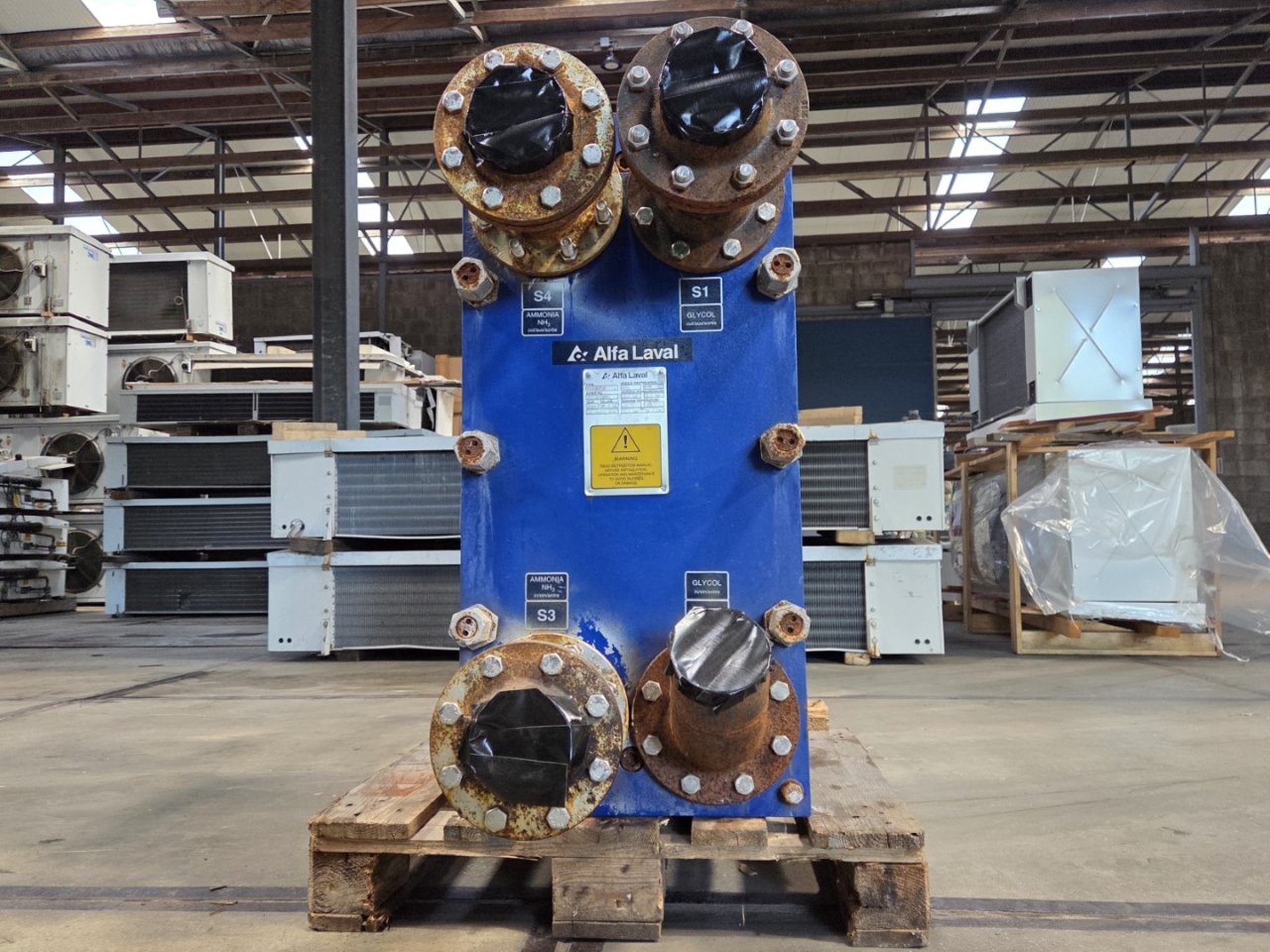
- Design Pressure M-Line
- >10 bar (145 psi)
- Marine Engine Room Modelle
- T6 (DN60, 800 kW) bis T35 (DN350, 35.000 kW)
- Marine FSRU Modelle
- TS45, T45, T50 (DN450-500, 45.000-55.000 kW)
- Temperaturbereich Standard
- 0–180°C (depending on model)
- FSRU Temperaturbereich
- -50 bis 150°C
- Plattentypen
- Chevron, Gemini Doppelwand, FlexFlow™
- M-Line (High Pressure Series: M3, M6, M10, M15)
- T-Series (Industrial: T2, T5, T6, T8, T10, T20, T25)
- AQ-Series (HVAC: AQ1, AQ2, AQ3, AQ4, AQ10)
- Marine Line (Engine Room: T6-T35; FSRU: TS45, T45, T50)
- Baseline (Competitive Line)
- Hygienic Line (Premium)
- Area: Gasket wear and embrittlementCheck: Inspect seals visually for cracks, hardening, swelling and discoloration; verify material compatibility with process fluids; check ClipGrip™ fastening. Aging symptoms and loss of elasticity are replacement indicators.
- Area: Clamping dimension and tightness (Tightening Dimension A)Check: Verify A-dimension per manufacturer specifications with caliper (metallic contact required). Keep bolts clean and lubricated. Avoid over-tightening. Perform regular re-tightening after operating hours. At too low A-dimension, pressure loss and leakage are to be expected.
- Area: Fouling and scale formation on plate surfacesCheck: Monitor pressure differential across heat exchanger (increase indicates deposits). Check heat duty versus design value. Optimize CIP intervals after performance audits. Deposits generate higher pump load (energy waste up to 8,000 kWh/year possible).
- Area: Plate corrosion and cracks / breakthroughsCheck: After disassembly, inspect plate surfaces for local measurements (pitting), cracks and perforation corrosion. Verify material compatibility with process fluid. Observe fatigue cracks especially at corners and transitions. When perforation occurs, plate is unrecoverable and must be replaced.
- Area: Pressure test and tightness inspectionCheck: After disassembly and cleaning, perform hydrostatic test per data sheet. Test pressure typically 1.5× operating pressure. Check external and internal leakage at all connections and plate edges. Document findings.
- Area: Plate sequence and alignment (5-point alignment)Check: After opening, verify plate sequence and honeycomb pattern (corrected chevron patterns must alternate). Activate/validate 5-point alignment system for larger units. Offset or misplacement leads to short-circuiting and reduced heat duty.
Type-universal inspection points for Alfa Laval Gasketed Plate Heat Exchangers (GPHE) (Alfa Laval, 2026-06). Per-model specs not auto-populated.
- Design Pressure M-Line
- >10 bar (145 psi)
- Marine Engine Room Modelle
- T6 (DN60, 800 kW) bis T35 (DN350, 35.000 kW)
- Marine FSRU Modelle
- TS45, T45, T50 (DN450-500, 45.000-55.000 kW)
- Temperaturbereich Standard
- 0–180°C (depending on model)
- FSRU Temperaturbereich
- -50 bis 150°C
- Plattentypen
- Chevron, Gemini Doppelwand, FlexFlow™
- M-Line (High Pressure Series: M3, M6, M10, M15)
- T-Series (Industrial: T2, T5, T6, T8, T10, T20, T25)
- AQ-Series (HVAC: AQ1, AQ2, AQ3, AQ4, AQ10)
- Marine Line (Engine Room: T6-T35; FSRU: TS45, T45, T50)
- Baseline (Competitive Line)
- Hygienic Line (Premium)
- Area: Gasket wear and embrittlementCheck: Inspect seals visually for cracks, hardening, swelling and discoloration; verify material compatibility with process fluids; check ClipGrip™ fastening. Aging symptoms and loss of elasticity are replacement indicators.
- Area: Clamping dimension and tightness (Tightening Dimension A)Check: Verify A-dimension per manufacturer specifications with caliper (metallic contact required). Keep bolts clean and lubricated. Avoid over-tightening. Perform regular re-tightening after operating hours. At too low A-dimension, pressure loss and leakage are to be expected.
- Area: Fouling and scale formation on plate surfacesCheck: Monitor pressure differential across heat exchanger (increase indicates deposits). Check heat duty versus design value. Optimize CIP intervals after performance audits. Deposits generate higher pump load (energy waste up to 8,000 kWh/year possible).
- Area: Plate corrosion and cracks / breakthroughsCheck: After disassembly, inspect plate surfaces for local measurements (pitting), cracks and perforation corrosion. Verify material compatibility with process fluid. Observe fatigue cracks especially at corners and transitions. When perforation occurs, plate is unrecoverable and must be replaced.
- Area: Pressure test and tightness inspectionCheck: After disassembly and cleaning, perform hydrostatic test per data sheet. Test pressure typically 1.5× operating pressure. Check external and internal leakage at all connections and plate edges. Document findings.
- Area: Plate sequence and alignment (5-point alignment)Check: After opening, verify plate sequence and honeycomb pattern (corrected chevron patterns must alternate). Activate/validate 5-point alignment system for larger units. Offset or misplacement leads to short-circuiting and reduced heat duty.
Type-universal inspection points for Alfa Laval Gasketed Plate Heat Exchangers (GPHE) (Alfa Laval, 2026-06). Per-model specs not auto-populated.
- Design Pressure M-Line
- >10 bar (145 psi)
- Marine Engine Room Modelle
- T6 (DN60, 800 kW) bis T35 (DN350, 35.000 kW)
- Marine FSRU Modelle
- TS45, T45, T50 (DN450-500, 45.000-55.000 kW)
- Temperaturbereich Standard
- 0–180°C (depending on model)
- FSRU Temperaturbereich
- -50 bis 150°C
- Plattentypen
- Chevron, Gemini Doppelwand, FlexFlow™
- M-Line (High Pressure Series: M3, M6, M10, M15)
- T-Series (Industrial: T2, T5, T6, T8, T10, T20, T25)
- AQ-Series (HVAC: AQ1, AQ2, AQ3, AQ4, AQ10)
- Marine Line (Engine Room: T6-T35; FSRU: TS45, T45, T50)
- Baseline (Competitive Line)
- Hygienic Line (Premium)
- Area: Gasket wear and embrittlementCheck: Inspect seals visually for cracks, hardening, swelling and discoloration; verify material compatibility with process fluids; check ClipGrip™ fastening. Aging symptoms and loss of elasticity are replacement indicators.
- Area: Clamping dimension and tightness (Tightening Dimension A)Check: Verify A-dimension per manufacturer specifications with caliper (metallic contact required). Keep bolts clean and lubricated. Avoid over-tightening. Perform regular re-tightening after operating hours. At too low A-dimension, pressure loss and leakage are to be expected.
- Area: Fouling and scale formation on plate surfacesCheck: Monitor pressure differential across heat exchanger (increase indicates deposits). Check heat duty versus design value. Optimize CIP intervals after performance audits. Deposits generate higher pump load (energy waste up to 8,000 kWh/year possible).
- Area: Plate corrosion and cracks / breakthroughsCheck: After disassembly, inspect plate surfaces for local measurements (pitting), cracks and perforation corrosion. Verify material compatibility with process fluid. Observe fatigue cracks especially at corners and transitions. When perforation occurs, plate is unrecoverable and must be replaced.
- Area: Pressure test and tightness inspectionCheck: After disassembly and cleaning, perform hydrostatic test per data sheet. Test pressure typically 1.5× operating pressure. Check external and internal leakage at all connections and plate edges. Document findings.
- Area: Plate sequence and alignment (5-point alignment)Check: After opening, verify plate sequence and honeycomb pattern (corrected chevron patterns must alternate). Activate/validate 5-point alignment system for larger units. Offset or misplacement leads to short-circuiting and reduced heat duty.
Type-universal inspection points for Alfa Laval Gasketed Plate Heat Exchangers (GPHE) (Alfa Laval, 2026-06). Per-model specs not auto-populated.

- Design Pressure M-Line
- >10 bar (145 psi)
- Marine Engine Room Modelle
- T6 (DN60, 800 kW) bis T35 (DN350, 35.000 kW)
- Marine FSRU Modelle
- TS45, T45, T50 (DN450-500, 45.000-55.000 kW)
- Temperaturbereich Standard
- 0–180°C (depending on model)
- FSRU Temperaturbereich
- -50 bis 150°C
- Plattentypen
- Chevron, Gemini Doppelwand, FlexFlow™
- M-Line (High Pressure Series: M3, M6, M10, M15)
- T-Series (Industrial: T2, T5, T6, T8, T10, T20, T25)
- AQ-Series (HVAC: AQ1, AQ2, AQ3, AQ4, AQ10)
- Marine Line (Engine Room: T6-T35; FSRU: TS45, T45, T50)
- Baseline (Competitive Line)
- Hygienic Line (Premium)
- Area: Gasket wear and embrittlementCheck: Inspect seals visually for cracks, hardening, swelling and discoloration; verify material compatibility with process fluids; check ClipGrip™ fastening. Aging symptoms and loss of elasticity are replacement indicators.
- Area: Clamping dimension and tightness (Tightening Dimension A)Check: Verify A-dimension per manufacturer specifications with caliper (metallic contact required). Keep bolts clean and lubricated. Avoid over-tightening. Perform regular re-tightening after operating hours. At too low A-dimension, pressure loss and leakage are to be expected.
- Area: Fouling and scale formation on plate surfacesCheck: Monitor pressure differential across heat exchanger (increase indicates deposits). Check heat duty versus design value. Optimize CIP intervals after performance audits. Deposits generate higher pump load (energy waste up to 8,000 kWh/year possible).
- Area: Plate corrosion and cracks / breakthroughsCheck: After disassembly, inspect plate surfaces for local measurements (pitting), cracks and perforation corrosion. Verify material compatibility with process fluid. Observe fatigue cracks especially at corners and transitions. When perforation occurs, plate is unrecoverable and must be replaced.
- Area: Pressure test and tightness inspectionCheck: After disassembly and cleaning, perform hydrostatic test per data sheet. Test pressure typically 1.5× operating pressure. Check external and internal leakage at all connections and plate edges. Document findings.
- Area: Plate sequence and alignment (5-point alignment)Check: After opening, verify plate sequence and honeycomb pattern (corrected chevron patterns must alternate). Activate/validate 5-point alignment system for larger units. Offset or misplacement leads to short-circuiting and reduced heat duty.
Type-universal inspection points for Alfa Laval Gasketed Plate Heat Exchangers (GPHE) (Alfa Laval, 2026-06). Per-model specs not auto-populated.
- Design Pressure M-Line
- >10 bar (145 psi)
- Marine Engine Room Modelle
- T6 (DN60, 800 kW) bis T35 (DN350, 35.000 kW)
- Marine FSRU Modelle
- TS45, T45, T50 (DN450-500, 45.000-55.000 kW)
- Temperaturbereich Standard
- 0–180°C (depending on model)
- FSRU Temperaturbereich
- -50 bis 150°C
- Plattentypen
- Chevron, Gemini Doppelwand, FlexFlow™
- M-Line (High Pressure Series: M3, M6, M10, M15)
- T-Series (Industrial: T2, T5, T6, T8, T10, T20, T25)
- AQ-Series (HVAC: AQ1, AQ2, AQ3, AQ4, AQ10)
- Marine Line (Engine Room: T6-T35; FSRU: TS45, T45, T50)
- Baseline (Competitive Line)
- Hygienic Line (Premium)
- Area: Gasket wear and embrittlementCheck: Inspect seals visually for cracks, hardening, swelling and discoloration; verify material compatibility with process fluids; check ClipGrip™ fastening. Aging symptoms and loss of elasticity are replacement indicators.
- Area: Clamping dimension and tightness (Tightening Dimension A)Check: Verify A-dimension per manufacturer specifications with caliper (metallic contact required). Keep bolts clean and lubricated. Avoid over-tightening. Perform regular re-tightening after operating hours. At too low A-dimension, pressure loss and leakage are to be expected.
- Area: Fouling and scale formation on plate surfacesCheck: Monitor pressure differential across heat exchanger (increase indicates deposits). Check heat duty versus design value. Optimize CIP intervals after performance audits. Deposits generate higher pump load (energy waste up to 8,000 kWh/year possible).
- Area: Plate corrosion and cracks / breakthroughsCheck: After disassembly, inspect plate surfaces for local measurements (pitting), cracks and perforation corrosion. Verify material compatibility with process fluid. Observe fatigue cracks especially at corners and transitions. When perforation occurs, plate is unrecoverable and must be replaced.
- Area: Pressure test and tightness inspectionCheck: After disassembly and cleaning, perform hydrostatic test per data sheet. Test pressure typically 1.5× operating pressure. Check external and internal leakage at all connections and plate edges. Document findings.
- Area: Plate sequence and alignment (5-point alignment)Check: After opening, verify plate sequence and honeycomb pattern (corrected chevron patterns must alternate). Activate/validate 5-point alignment system for larger units. Offset or misplacement leads to short-circuiting and reduced heat duty.
Type-universal inspection points for Alfa Laval Gasketed Plate Heat Exchangers (GPHE) (Alfa Laval, 2026-06). Per-model specs not auto-populated.
- Design Pressure M-Line
- >10 bar (145 psi)
- Marine Engine Room Modelle
- T6 (DN60, 800 kW) bis T35 (DN350, 35.000 kW)
- Marine FSRU Modelle
- TS45, T45, T50 (DN450-500, 45.000-55.000 kW)
- Temperaturbereich Standard
- 0–180°C (depending on model)
- FSRU Temperaturbereich
- -50 bis 150°C
- Plattentypen
- Chevron, Gemini Doppelwand, FlexFlow™
- M-Line (High Pressure Series: M3, M6, M10, M15)
- T-Series (Industrial: T2, T5, T6, T8, T10, T20, T25)
- AQ-Series (HVAC: AQ1, AQ2, AQ3, AQ4, AQ10)
- Marine Line (Engine Room: T6-T35; FSRU: TS45, T45, T50)
- Baseline (Competitive Line)
- Hygienic Line (Premium)
- Area: Gasket wear and embrittlementCheck: Inspect seals visually for cracks, hardening, swelling and discoloration; verify material compatibility with process fluids; check ClipGrip™ fastening. Aging symptoms and loss of elasticity are replacement indicators.
- Area: Clamping dimension and tightness (Tightening Dimension A)Check: Verify A-dimension per manufacturer specifications with caliper (metallic contact required). Keep bolts clean and lubricated. Avoid over-tightening. Perform regular re-tightening after operating hours. At too low A-dimension, pressure loss and leakage are to be expected.
- Area: Fouling and scale formation on plate surfacesCheck: Monitor pressure differential across heat exchanger (increase indicates deposits). Check heat duty versus design value. Optimize CIP intervals after performance audits. Deposits generate higher pump load (energy waste up to 8,000 kWh/year possible).
- Area: Plate corrosion and cracks / breakthroughsCheck: After disassembly, inspect plate surfaces for local measurements (pitting), cracks and perforation corrosion. Verify material compatibility with process fluid. Observe fatigue cracks especially at corners and transitions. When perforation occurs, plate is unrecoverable and must be replaced.
- Area: Pressure test and tightness inspectionCheck: After disassembly and cleaning, perform hydrostatic test per data sheet. Test pressure typically 1.5× operating pressure. Check external and internal leakage at all connections and plate edges. Document findings.
- Area: Plate sequence and alignment (5-point alignment)Check: After opening, verify plate sequence and honeycomb pattern (corrected chevron patterns must alternate). Activate/validate 5-point alignment system for larger units. Offset or misplacement leads to short-circuiting and reduced heat duty.
Type-universal inspection points for Alfa Laval Gasketed Plate Heat Exchangers (GPHE) (Alfa Laval, 2026-06). Per-model specs not auto-populated.
- Design Pressure M-Line
- >10 bar (145 psi)
- Marine Engine Room Modelle
- T6 (DN60, 800 kW) bis T35 (DN350, 35.000 kW)
- Marine FSRU Modelle
- TS45, T45, T50 (DN450-500, 45.000-55.000 kW)
- Temperaturbereich Standard
- 0–180°C (depending on model)
- FSRU Temperaturbereich
- -50 bis 150°C
- Plattentypen
- Chevron, Gemini Doppelwand, FlexFlow™
- M-Line (High Pressure Series: M3, M6, M10, M15)
- T-Series (Industrial: T2, T5, T6, T8, T10, T20, T25)
- AQ-Series (HVAC: AQ1, AQ2, AQ3, AQ4, AQ10)
- Marine Line (Engine Room: T6-T35; FSRU: TS45, T45, T50)
- Baseline (Competitive Line)
- Hygienic Line (Premium)
- Area: Gasket wear and embrittlementCheck: Inspect seals visually for cracks, hardening, swelling and discoloration; verify material compatibility with process fluids; check ClipGrip™ fastening. Aging symptoms and loss of elasticity are replacement indicators.
- Area: Clamping dimension and tightness (Tightening Dimension A)Check: Verify A-dimension per manufacturer specifications with caliper (metallic contact required). Keep bolts clean and lubricated. Avoid over-tightening. Perform regular re-tightening after operating hours. At too low A-dimension, pressure loss and leakage are to be expected.
- Area: Fouling and scale formation on plate surfacesCheck: Monitor pressure differential across heat exchanger (increase indicates deposits). Check heat duty versus design value. Optimize CIP intervals after performance audits. Deposits generate higher pump load (energy waste up to 8,000 kWh/year possible).
- Area: Plate corrosion and cracks / breakthroughsCheck: After disassembly, inspect plate surfaces for local measurements (pitting), cracks and perforation corrosion. Verify material compatibility with process fluid. Observe fatigue cracks especially at corners and transitions. When perforation occurs, plate is unrecoverable and must be replaced.
- Area: Pressure test and tightness inspectionCheck: After disassembly and cleaning, perform hydrostatic test per data sheet. Test pressure typically 1.5× operating pressure. Check external and internal leakage at all connections and plate edges. Document findings.
- Area: Plate sequence and alignment (5-point alignment)Check: After opening, verify plate sequence and honeycomb pattern (corrected chevron patterns must alternate). Activate/validate 5-point alignment system for larger units. Offset or misplacement leads to short-circuiting and reduced heat duty.
Type-universal inspection points for Alfa Laval Gasketed Plate Heat Exchangers (GPHE) (Alfa Laval, 2026-06). Per-model specs not auto-populated.
- Design Pressure M-Line
- >10 bar (145 psi)
- Marine Engine Room Modelle
- T6 (DN60, 800 kW) bis T35 (DN350, 35.000 kW)
- Marine FSRU Modelle
- TS45, T45, T50 (DN450-500, 45.000-55.000 kW)
- Temperaturbereich Standard
- 0–180°C (depending on model)
- FSRU Temperaturbereich
- -50 bis 150°C
- Plattentypen
- Chevron, Gemini Doppelwand, FlexFlow™
- M-Line (High Pressure Series: M3, M6, M10, M15)
- T-Series (Industrial: T2, T5, T6, T8, T10, T20, T25)
- AQ-Series (HVAC: AQ1, AQ2, AQ3, AQ4, AQ10)
- Marine Line (Engine Room: T6-T35; FSRU: TS45, T45, T50)
- Baseline (Competitive Line)
- Hygienic Line (Premium)
- Area: Gasket wear and embrittlementCheck: Inspect seals visually for cracks, hardening, swelling and discoloration; verify material compatibility with process fluids; check ClipGrip™ fastening. Aging symptoms and loss of elasticity are replacement indicators.
- Area: Clamping dimension and tightness (Tightening Dimension A)Check: Verify A-dimension per manufacturer specifications with caliper (metallic contact required). Keep bolts clean and lubricated. Avoid over-tightening. Perform regular re-tightening after operating hours. At too low A-dimension, pressure loss and leakage are to be expected.
- Area: Fouling and scale formation on plate surfacesCheck: Monitor pressure differential across heat exchanger (increase indicates deposits). Check heat duty versus design value. Optimize CIP intervals after performance audits. Deposits generate higher pump load (energy waste up to 8,000 kWh/year possible).
- Area: Plate corrosion and cracks / breakthroughsCheck: After disassembly, inspect plate surfaces for local measurements (pitting), cracks and perforation corrosion. Verify material compatibility with process fluid. Observe fatigue cracks especially at corners and transitions. When perforation occurs, plate is unrecoverable and must be replaced.
- Area: Pressure test and tightness inspectionCheck: After disassembly and cleaning, perform hydrostatic test per data sheet. Test pressure typically 1.5× operating pressure. Check external and internal leakage at all connections and plate edges. Document findings.
- Area: Plate sequence and alignment (5-point alignment)Check: After opening, verify plate sequence and honeycomb pattern (corrected chevron patterns must alternate). Activate/validate 5-point alignment system for larger units. Offset or misplacement leads to short-circuiting and reduced heat duty.
Type-universal inspection points for Alfa Laval Gasketed Plate Heat Exchangers (GPHE) (Alfa Laval, 2026-06). Per-model specs not auto-populated.
- Design Pressure M-Line
- >10 bar (145 psi)
- Marine Engine Room Modelle
- T6 (DN60, 800 kW) bis T35 (DN350, 35.000 kW)
- Marine FSRU Modelle
- TS45, T45, T50 (DN450-500, 45.000-55.000 kW)
- Temperaturbereich Standard
- 0–180°C (depending on model)
- FSRU Temperaturbereich
- -50 bis 150°C
- Plattentypen
- Chevron, Gemini Doppelwand, FlexFlow™
- M-Line (High Pressure Series: M3, M6, M10, M15)
- T-Series (Industrial: T2, T5, T6, T8, T10, T20, T25)
- AQ-Series (HVAC: AQ1, AQ2, AQ3, AQ4, AQ10)
- Marine Line (Engine Room: T6-T35; FSRU: TS45, T45, T50)
- Baseline (Competitive Line)
- Hygienic Line (Premium)
- Area: Gasket wear and embrittlementCheck: Inspect seals visually for cracks, hardening, swelling and discoloration; verify material compatibility with process fluids; check ClipGrip™ fastening. Aging symptoms and loss of elasticity are replacement indicators.
- Area: Clamping dimension and tightness (Tightening Dimension A)Check: Verify A-dimension per manufacturer specifications with caliper (metallic contact required). Keep bolts clean and lubricated. Avoid over-tightening. Perform regular re-tightening after operating hours. At too low A-dimension, pressure loss and leakage are to be expected.
- Area: Fouling and scale formation on plate surfacesCheck: Monitor pressure differential across heat exchanger (increase indicates deposits). Check heat duty versus design value. Optimize CIP intervals after performance audits. Deposits generate higher pump load (energy waste up to 8,000 kWh/year possible).
- Area: Plate corrosion and cracks / breakthroughsCheck: After disassembly, inspect plate surfaces for local measurements (pitting), cracks and perforation corrosion. Verify material compatibility with process fluid. Observe fatigue cracks especially at corners and transitions. When perforation occurs, plate is unrecoverable and must be replaced.
- Area: Pressure test and tightness inspectionCheck: After disassembly and cleaning, perform hydrostatic test per data sheet. Test pressure typically 1.5× operating pressure. Check external and internal leakage at all connections and plate edges. Document findings.
- Area: Plate sequence and alignment (5-point alignment)Check: After opening, verify plate sequence and honeycomb pattern (corrected chevron patterns must alternate). Activate/validate 5-point alignment system for larger units. Offset or misplacement leads to short-circuiting and reduced heat duty.
Type-universal inspection points for Alfa Laval Gasketed Plate Heat Exchangers (GPHE) (Alfa Laval, 2026-06). Per-model specs not auto-populated.
- Design Pressure M-Line
- >10 bar (145 psi)
- Marine Engine Room Modelle
- T6 (DN60, 800 kW) bis T35 (DN350, 35.000 kW)
- Marine FSRU Modelle
- TS45, T45, T50 (DN450-500, 45.000-55.000 kW)
- Temperaturbereich Standard
- 0–180°C (depending on model)
- FSRU Temperaturbereich
- -50 bis 150°C
- Plattentypen
- Chevron, Gemini Doppelwand, FlexFlow™
- M-Line (High Pressure Series: M3, M6, M10, M15)
- T-Series (Industrial: T2, T5, T6, T8, T10, T20, T25)
- AQ-Series (HVAC: AQ1, AQ2, AQ3, AQ4, AQ10)
- Marine Line (Engine Room: T6-T35; FSRU: TS45, T45, T50)
- Baseline (Competitive Line)
- Hygienic Line (Premium)
- Area: Gasket wear and embrittlementCheck: Inspect seals visually for cracks, hardening, swelling and discoloration; verify material compatibility with process fluids; check ClipGrip™ fastening. Aging symptoms and loss of elasticity are replacement indicators.
- Area: Clamping dimension and tightness (Tightening Dimension A)Check: Verify A-dimension per manufacturer specifications with caliper (metallic contact required). Keep bolts clean and lubricated. Avoid over-tightening. Perform regular re-tightening after operating hours. At too low A-dimension, pressure loss and leakage are to be expected.
- Area: Fouling and scale formation on plate surfacesCheck: Monitor pressure differential across heat exchanger (increase indicates deposits). Check heat duty versus design value. Optimize CIP intervals after performance audits. Deposits generate higher pump load (energy waste up to 8,000 kWh/year possible).
- Area: Plate corrosion and cracks / breakthroughsCheck: After disassembly, inspect plate surfaces for local measurements (pitting), cracks and perforation corrosion. Verify material compatibility with process fluid. Observe fatigue cracks especially at corners and transitions. When perforation occurs, plate is unrecoverable and must be replaced.
- Area: Pressure test and tightness inspectionCheck: After disassembly and cleaning, perform hydrostatic test per data sheet. Test pressure typically 1.5× operating pressure. Check external and internal leakage at all connections and plate edges. Document findings.
- Area: Plate sequence and alignment (5-point alignment)Check: After opening, verify plate sequence and honeycomb pattern (corrected chevron patterns must alternate). Activate/validate 5-point alignment system for larger units. Offset or misplacement leads to short-circuiting and reduced heat duty.
Type-universal inspection points for Alfa Laval Gasketed Plate Heat Exchangers (GPHE) (Alfa Laval, 2026-06). Per-model specs not auto-populated.
- Design Pressure M-Line
- >10 bar (145 psi)
- Marine Engine Room Modelle
- T6 (DN60, 800 kW) bis T35 (DN350, 35.000 kW)
- Marine FSRU Modelle
- TS45, T45, T50 (DN450-500, 45.000-55.000 kW)
- Temperaturbereich Standard
- 0–180°C (depending on model)
- FSRU Temperaturbereich
- -50 bis 150°C
- Plattentypen
- Chevron, Gemini Doppelwand, FlexFlow™
- M-Line (High Pressure Series: M3, M6, M10, M15)
- T-Series (Industrial: T2, T5, T6, T8, T10, T20, T25)
- AQ-Series (HVAC: AQ1, AQ2, AQ3, AQ4, AQ10)
- Marine Line (Engine Room: T6-T35; FSRU: TS45, T45, T50)
- Baseline (Competitive Line)
- Hygienic Line (Premium)
- Area: Gasket wear and embrittlementCheck: Inspect seals visually for cracks, hardening, swelling and discoloration; verify material compatibility with process fluids; check ClipGrip™ fastening. Aging symptoms and loss of elasticity are replacement indicators.
- Area: Clamping dimension and tightness (Tightening Dimension A)Check: Verify A-dimension per manufacturer specifications with caliper (metallic contact required). Keep bolts clean and lubricated. Avoid over-tightening. Perform regular re-tightening after operating hours. At too low A-dimension, pressure loss and leakage are to be expected.
- Area: Fouling and scale formation on plate surfacesCheck: Monitor pressure differential across heat exchanger (increase indicates deposits). Check heat duty versus design value. Optimize CIP intervals after performance audits. Deposits generate higher pump load (energy waste up to 8,000 kWh/year possible).
- Area: Plate corrosion and cracks / breakthroughsCheck: After disassembly, inspect plate surfaces for local measurements (pitting), cracks and perforation corrosion. Verify material compatibility with process fluid. Observe fatigue cracks especially at corners and transitions. When perforation occurs, plate is unrecoverable and must be replaced.
- Area: Pressure test and tightness inspectionCheck: After disassembly and cleaning, perform hydrostatic test per data sheet. Test pressure typically 1.5× operating pressure. Check external and internal leakage at all connections and plate edges. Document findings.
- Area: Plate sequence and alignment (5-point alignment)Check: After opening, verify plate sequence and honeycomb pattern (corrected chevron patterns must alternate). Activate/validate 5-point alignment system for larger units. Offset or misplacement leads to short-circuiting and reduced heat duty.
Type-universal inspection points for Alfa Laval Gasketed Plate Heat Exchangers (GPHE) (Alfa Laval, 2026-06). Per-model specs not auto-populated.
- Design Pressure M-Line
- >10 bar (145 psi)
- Marine Engine Room Modelle
- T6 (DN60, 800 kW) bis T35 (DN350, 35.000 kW)
- Marine FSRU Modelle
- TS45, T45, T50 (DN450-500, 45.000-55.000 kW)
- Temperaturbereich Standard
- 0–180°C (depending on model)
- FSRU Temperaturbereich
- -50 bis 150°C
- Plattentypen
- Chevron, Gemini Doppelwand, FlexFlow™
- M-Line (High Pressure Series: M3, M6, M10, M15)
- T-Series (Industrial: T2, T5, T6, T8, T10, T20, T25)
- AQ-Series (HVAC: AQ1, AQ2, AQ3, AQ4, AQ10)
- Marine Line (Engine Room: T6-T35; FSRU: TS45, T45, T50)
- Baseline (Competitive Line)
- Hygienic Line (Premium)
- Area: Gasket wear and embrittlementCheck: Inspect seals visually for cracks, hardening, swelling and discoloration; verify material compatibility with process fluids; check ClipGrip™ fastening. Aging symptoms and loss of elasticity are replacement indicators.
- Area: Clamping dimension and tightness (Tightening Dimension A)Check: Verify A-dimension per manufacturer specifications with caliper (metallic contact required). Keep bolts clean and lubricated. Avoid over-tightening. Perform regular re-tightening after operating hours. At too low A-dimension, pressure loss and leakage are to be expected.
- Area: Fouling and scale formation on plate surfacesCheck: Monitor pressure differential across heat exchanger (increase indicates deposits). Check heat duty versus design value. Optimize CIP intervals after performance audits. Deposits generate higher pump load (energy waste up to 8,000 kWh/year possible).
- Area: Plate corrosion and cracks / breakthroughsCheck: After disassembly, inspect plate surfaces for local measurements (pitting), cracks and perforation corrosion. Verify material compatibility with process fluid. Observe fatigue cracks especially at corners and transitions. When perforation occurs, plate is unrecoverable and must be replaced.
- Area: Pressure test and tightness inspectionCheck: After disassembly and cleaning, perform hydrostatic test per data sheet. Test pressure typically 1.5× operating pressure. Check external and internal leakage at all connections and plate edges. Document findings.
- Area: Plate sequence and alignment (5-point alignment)Check: After opening, verify plate sequence and honeycomb pattern (corrected chevron patterns must alternate). Activate/validate 5-point alignment system for larger units. Offset or misplacement leads to short-circuiting and reduced heat duty.
Type-universal inspection points for Alfa Laval Gasketed Plate Heat Exchangers (GPHE) (Alfa Laval, 2026-06). Per-model specs not auto-populated.
- Design Pressure M-Line
- >10 bar (145 psi)
- Marine Engine Room Modelle
- T6 (DN60, 800 kW) bis T35 (DN350, 35.000 kW)
- Marine FSRU Modelle
- TS45, T45, T50 (DN450-500, 45.000-55.000 kW)
- Temperaturbereich Standard
- 0–180°C (depending on model)
- FSRU Temperaturbereich
- -50 bis 150°C
- Plattentypen
- Chevron, Gemini Doppelwand, FlexFlow™
- M-Line (High Pressure Series: M3, M6, M10, M15)
- T-Series (Industrial: T2, T5, T6, T8, T10, T20, T25)
- AQ-Series (HVAC: AQ1, AQ2, AQ3, AQ4, AQ10)
- Marine Line (Engine Room: T6-T35; FSRU: TS45, T45, T50)
- Baseline (Competitive Line)
- Hygienic Line (Premium)
- Area: Gasket wear and embrittlementCheck: Inspect seals visually for cracks, hardening, swelling and discoloration; verify material compatibility with process fluids; check ClipGrip™ fastening. Aging symptoms and loss of elasticity are replacement indicators.
- Area: Clamping dimension and tightness (Tightening Dimension A)Check: Verify A-dimension per manufacturer specifications with caliper (metallic contact required). Keep bolts clean and lubricated. Avoid over-tightening. Perform regular re-tightening after operating hours. At too low A-dimension, pressure loss and leakage are to be expected.
- Area: Fouling and scale formation on plate surfacesCheck: Monitor pressure differential across heat exchanger (increase indicates deposits). Check heat duty versus design value. Optimize CIP intervals after performance audits. Deposits generate higher pump load (energy waste up to 8,000 kWh/year possible).
- Area: Plate corrosion and cracks / breakthroughsCheck: After disassembly, inspect plate surfaces for local measurements (pitting), cracks and perforation corrosion. Verify material compatibility with process fluid. Observe fatigue cracks especially at corners and transitions. When perforation occurs, plate is unrecoverable and must be replaced.
- Area: Pressure test and tightness inspectionCheck: After disassembly and cleaning, perform hydrostatic test per data sheet. Test pressure typically 1.5× operating pressure. Check external and internal leakage at all connections and plate edges. Document findings.
- Area: Plate sequence and alignment (5-point alignment)Check: After opening, verify plate sequence and honeycomb pattern (corrected chevron patterns must alternate). Activate/validate 5-point alignment system for larger units. Offset or misplacement leads to short-circuiting and reduced heat duty.
Type-universal inspection points for Alfa Laval Gasketed Plate Heat Exchangers (GPHE) (Alfa Laval, 2026-06). Per-model specs not auto-populated.
- Design Pressure M-Line
- >10 bar (145 psi)
- Marine Engine Room Modelle
- T6 (DN60, 800 kW) bis T35 (DN350, 35.000 kW)
- Marine FSRU Modelle
- TS45, T45, T50 (DN450-500, 45.000-55.000 kW)
- Temperaturbereich Standard
- 0–180°C (depending on model)
- FSRU Temperaturbereich
- -50 bis 150°C
- Plattentypen
- Chevron, Gemini Doppelwand, FlexFlow™
- M-Line (High Pressure Series: M3, M6, M10, M15)
- T-Series (Industrial: T2, T5, T6, T8, T10, T20, T25)
- AQ-Series (HVAC: AQ1, AQ2, AQ3, AQ4, AQ10)
- Marine Line (Engine Room: T6-T35; FSRU: TS45, T45, T50)
- Baseline (Competitive Line)
- Hygienic Line (Premium)
- Area: Gasket wear and embrittlementCheck: Inspect seals visually for cracks, hardening, swelling and discoloration; verify material compatibility with process fluids; check ClipGrip™ fastening. Aging symptoms and loss of elasticity are replacement indicators.
- Area: Clamping dimension and tightness (Tightening Dimension A)Check: Verify A-dimension per manufacturer specifications with caliper (metallic contact required). Keep bolts clean and lubricated. Avoid over-tightening. Perform regular re-tightening after operating hours. At too low A-dimension, pressure loss and leakage are to be expected.
- Area: Fouling and scale formation on plate surfacesCheck: Monitor pressure differential across heat exchanger (increase indicates deposits). Check heat duty versus design value. Optimize CIP intervals after performance audits. Deposits generate higher pump load (energy waste up to 8,000 kWh/year possible).
- Area: Plate corrosion and cracks / breakthroughsCheck: After disassembly, inspect plate surfaces for local measurements (pitting), cracks and perforation corrosion. Verify material compatibility with process fluid. Observe fatigue cracks especially at corners and transitions. When perforation occurs, plate is unrecoverable and must be replaced.
- Area: Pressure test and tightness inspectionCheck: After disassembly and cleaning, perform hydrostatic test per data sheet. Test pressure typically 1.5× operating pressure. Check external and internal leakage at all connections and plate edges. Document findings.
- Area: Plate sequence and alignment (5-point alignment)Check: After opening, verify plate sequence and honeycomb pattern (corrected chevron patterns must alternate). Activate/validate 5-point alignment system for larger units. Offset or misplacement leads to short-circuiting and reduced heat duty.
Type-universal inspection points for Alfa Laval Gasketed Plate Heat Exchangers (GPHE) (Alfa Laval, 2026-06). Per-model specs not auto-populated.

- Design Pressure M-Line
- >10 bar (145 psi)
- Marine Engine Room Modelle
- T6 (DN60, 800 kW) bis T35 (DN350, 35.000 kW)
- Marine FSRU Modelle
- TS45, T45, T50 (DN450-500, 45.000-55.000 kW)
- Temperaturbereich Standard
- 0–180°C (depending on model)
- FSRU Temperaturbereich
- -50 bis 150°C
- Plattentypen
- Chevron, Gemini Doppelwand, FlexFlow™
- M-Line (High Pressure Series: M3, M6, M10, M15)
- T-Series (Industrial: T2, T5, T6, T8, T10, T20, T25)
- AQ-Series (HVAC: AQ1, AQ2, AQ3, AQ4, AQ10)
- Marine Line (Engine Room: T6-T35; FSRU: TS45, T45, T50)
- Baseline (Competitive Line)
- Hygienic Line (Premium)
- Area: Gasket wear and embrittlementCheck: Inspect seals visually for cracks, hardening, swelling and discoloration; verify material compatibility with process fluids; check ClipGrip™ fastening. Aging symptoms and loss of elasticity are replacement indicators.
- Area: Clamping dimension and tightness (Tightening Dimension A)Check: Verify A-dimension per manufacturer specifications with caliper (metallic contact required). Keep bolts clean and lubricated. Avoid over-tightening. Perform regular re-tightening after operating hours. At too low A-dimension, pressure loss and leakage are to be expected.
- Area: Fouling and scale formation on plate surfacesCheck: Monitor pressure differential across heat exchanger (increase indicates deposits). Check heat duty versus design value. Optimize CIP intervals after performance audits. Deposits generate higher pump load (energy waste up to 8,000 kWh/year possible).
- Area: Plate corrosion and cracks / breakthroughsCheck: After disassembly, inspect plate surfaces for local measurements (pitting), cracks and perforation corrosion. Verify material compatibility with process fluid. Observe fatigue cracks especially at corners and transitions. When perforation occurs, plate is unrecoverable and must be replaced.
- Area: Pressure test and tightness inspectionCheck: After disassembly and cleaning, perform hydrostatic test per data sheet. Test pressure typically 1.5× operating pressure. Check external and internal leakage at all connections and plate edges. Document findings.
- Area: Plate sequence and alignment (5-point alignment)Check: After opening, verify plate sequence and honeycomb pattern (corrected chevron patterns must alternate). Activate/validate 5-point alignment system for larger units. Offset or misplacement leads to short-circuiting and reduced heat duty.
Type-universal inspection points for Alfa Laval Gasketed Plate Heat Exchangers (GPHE) (Alfa Laval, 2026-06). Per-model specs not auto-populated.

- Design Pressure M-Line
- >10 bar (145 psi)
- Marine Engine Room Modelle
- T6 (DN60, 800 kW) bis T35 (DN350, 35.000 kW)
- Marine FSRU Modelle
- TS45, T45, T50 (DN450-500, 45.000-55.000 kW)
- Temperaturbereich Standard
- 0–180°C (depending on model)
- FSRU Temperaturbereich
- -50 bis 150°C
- Plattentypen
- Chevron, Gemini Doppelwand, FlexFlow™
- M-Line (High Pressure Series: M3, M6, M10, M15)
- T-Series (Industrial: T2, T5, T6, T8, T10, T20, T25)
- AQ-Series (HVAC: AQ1, AQ2, AQ3, AQ4, AQ10)
- Marine Line (Engine Room: T6-T35; FSRU: TS45, T45, T50)
- Baseline (Competitive Line)
- Hygienic Line (Premium)
- Area: Gasket wear and embrittlementCheck: Inspect seals visually for cracks, hardening, swelling and discoloration; verify material compatibility with process fluids; check ClipGrip™ fastening. Aging symptoms and loss of elasticity are replacement indicators.
- Area: Clamping dimension and tightness (Tightening Dimension A)Check: Verify A-dimension per manufacturer specifications with caliper (metallic contact required). Keep bolts clean and lubricated. Avoid over-tightening. Perform regular re-tightening after operating hours. At too low A-dimension, pressure loss and leakage are to be expected.
- Area: Fouling and scale formation on plate surfacesCheck: Monitor pressure differential across heat exchanger (increase indicates deposits). Check heat duty versus design value. Optimize CIP intervals after performance audits. Deposits generate higher pump load (energy waste up to 8,000 kWh/year possible).
- Area: Plate corrosion and cracks / breakthroughsCheck: After disassembly, inspect plate surfaces for local measurements (pitting), cracks and perforation corrosion. Verify material compatibility with process fluid. Observe fatigue cracks especially at corners and transitions. When perforation occurs, plate is unrecoverable and must be replaced.
- Area: Pressure test and tightness inspectionCheck: After disassembly and cleaning, perform hydrostatic test per data sheet. Test pressure typically 1.5× operating pressure. Check external and internal leakage at all connections and plate edges. Document findings.
- Area: Plate sequence and alignment (5-point alignment)Check: After opening, verify plate sequence and honeycomb pattern (corrected chevron patterns must alternate). Activate/validate 5-point alignment system for larger units. Offset or misplacement leads to short-circuiting and reduced heat duty.
Type-universal inspection points for Alfa Laval Gasketed Plate Heat Exchangers (GPHE) (Alfa Laval, 2026-06). Per-model specs not auto-populated.

- Design Pressure M-Line
- >10 bar (145 psi)
- Marine Engine Room Modelle
- T6 (DN60, 800 kW) bis T35 (DN350, 35.000 kW)
- Marine FSRU Modelle
- TS45, T45, T50 (DN450-500, 45.000-55.000 kW)
- Temperaturbereich Standard
- 0–180°C (depending on model)
- FSRU Temperaturbereich
- -50 bis 150°C
- Plattentypen
- Chevron, Gemini Doppelwand, FlexFlow™
- M-Line (High Pressure Series: M3, M6, M10, M15)
- T-Series (Industrial: T2, T5, T6, T8, T10, T20, T25)
- AQ-Series (HVAC: AQ1, AQ2, AQ3, AQ4, AQ10)
- Marine Line (Engine Room: T6-T35; FSRU: TS45, T45, T50)
- Baseline (Competitive Line)
- Hygienic Line (Premium)
- Area: Gasket wear and embrittlementCheck: Inspect seals visually for cracks, hardening, swelling and discoloration; verify material compatibility with process fluids; check ClipGrip™ fastening. Aging symptoms and loss of elasticity are replacement indicators.
- Area: Clamping dimension and tightness (Tightening Dimension A)Check: Verify A-dimension per manufacturer specifications with caliper (metallic contact required). Keep bolts clean and lubricated. Avoid over-tightening. Perform regular re-tightening after operating hours. At too low A-dimension, pressure loss and leakage are to be expected.
- Area: Fouling and scale formation on plate surfacesCheck: Monitor pressure differential across heat exchanger (increase indicates deposits). Check heat duty versus design value. Optimize CIP intervals after performance audits. Deposits generate higher pump load (energy waste up to 8,000 kWh/year possible).
- Area: Plate corrosion and cracks / breakthroughsCheck: After disassembly, inspect plate surfaces for local measurements (pitting), cracks and perforation corrosion. Verify material compatibility with process fluid. Observe fatigue cracks especially at corners and transitions. When perforation occurs, plate is unrecoverable and must be replaced.
- Area: Pressure test and tightness inspectionCheck: After disassembly and cleaning, perform hydrostatic test per data sheet. Test pressure typically 1.5× operating pressure. Check external and internal leakage at all connections and plate edges. Document findings.
- Area: Plate sequence and alignment (5-point alignment)Check: After opening, verify plate sequence and honeycomb pattern (corrected chevron patterns must alternate). Activate/validate 5-point alignment system for larger units. Offset or misplacement leads to short-circuiting and reduced heat duty.
Type-universal inspection points for Alfa Laval Gasketed Plate Heat Exchangers (GPHE) (Alfa Laval, 2026-06). Per-model specs not auto-populated.
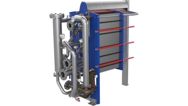
- Design Pressure M-Line
- >10 bar (145 psi)
- Marine Engine Room Modelle
- T6 (DN60, 800 kW) bis T35 (DN350, 35.000 kW)
- Marine FSRU Modelle
- TS45, T45, T50 (DN450-500, 45.000-55.000 kW)
- Temperaturbereich Standard
- 0–180°C (depending on model)
- FSRU Temperaturbereich
- -50 bis 150°C
- Plattentypen
- Chevron, Gemini Doppelwand, FlexFlow™
- M-Line (High Pressure Series: M3, M6, M10, M15)
- T-Series (Industrial: T2, T5, T6, T8, T10, T20, T25)
- AQ-Series (HVAC: AQ1, AQ2, AQ3, AQ4, AQ10)
- Marine Line (Engine Room: T6-T35; FSRU: TS45, T45, T50)
- Baseline (Competitive Line)
- Hygienic Line (Premium)
- Area: Gasket wear and embrittlementCheck: Inspect seals visually for cracks, hardening, swelling and discoloration; verify material compatibility with process fluids; check ClipGrip™ fastening. Aging symptoms and loss of elasticity are replacement indicators.
- Area: Clamping dimension and tightness (Tightening Dimension A)Check: Verify A-dimension per manufacturer specifications with caliper (metallic contact required). Keep bolts clean and lubricated. Avoid over-tightening. Perform regular re-tightening after operating hours. At too low A-dimension, pressure loss and leakage are to be expected.
- Area: Fouling and scale formation on plate surfacesCheck: Monitor pressure differential across heat exchanger (increase indicates deposits). Check heat duty versus design value. Optimize CIP intervals after performance audits. Deposits generate higher pump load (energy waste up to 8,000 kWh/year possible).
- Area: Plate corrosion and cracks / breakthroughsCheck: After disassembly, inspect plate surfaces for local measurements (pitting), cracks and perforation corrosion. Verify material compatibility with process fluid. Observe fatigue cracks especially at corners and transitions. When perforation occurs, plate is unrecoverable and must be replaced.
- Area: Pressure test and tightness inspectionCheck: After disassembly and cleaning, perform hydrostatic test per data sheet. Test pressure typically 1.5× operating pressure. Check external and internal leakage at all connections and plate edges. Document findings.
- Area: Plate sequence and alignment (5-point alignment)Check: After opening, verify plate sequence and honeycomb pattern (corrected chevron patterns must alternate). Activate/validate 5-point alignment system for larger units. Offset or misplacement leads to short-circuiting and reduced heat duty.
Type-universal inspection points for Alfa Laval Gasketed Plate Heat Exchangers (GPHE) (Alfa Laval, 2026-06). Per-model specs not auto-populated.

- Design Pressure M-Line
- >10 bar (145 psi)
- Marine Engine Room Modelle
- T6 (DN60, 800 kW) bis T35 (DN350, 35.000 kW)
- Marine FSRU Modelle
- TS45, T45, T50 (DN450-500, 45.000-55.000 kW)
- Temperaturbereich Standard
- 0–180°C (depending on model)
- FSRU Temperaturbereich
- -50 bis 150°C
- Plattentypen
- Chevron, Gemini Doppelwand, FlexFlow™
- M-Line (High Pressure Series: M3, M6, M10, M15)
- T-Series (Industrial: T2, T5, T6, T8, T10, T20, T25)
- AQ-Series (HVAC: AQ1, AQ2, AQ3, AQ4, AQ10)
- Marine Line (Engine Room: T6-T35; FSRU: TS45, T45, T50)
- Baseline (Competitive Line)
- Hygienic Line (Premium)
- Area: Gasket wear and embrittlementCheck: Inspect seals visually for cracks, hardening, swelling and discoloration; verify material compatibility with process fluids; check ClipGrip™ fastening. Aging symptoms and loss of elasticity are replacement indicators.
- Area: Clamping dimension and tightness (Tightening Dimension A)Check: Verify A-dimension per manufacturer specifications with caliper (metallic contact required). Keep bolts clean and lubricated. Avoid over-tightening. Perform regular re-tightening after operating hours. At too low A-dimension, pressure loss and leakage are to be expected.
- Area: Fouling and scale formation on plate surfacesCheck: Monitor pressure differential across heat exchanger (increase indicates deposits). Check heat duty versus design value. Optimize CIP intervals after performance audits. Deposits generate higher pump load (energy waste up to 8,000 kWh/year possible).
- Area: Plate corrosion and cracks / breakthroughsCheck: After disassembly, inspect plate surfaces for local measurements (pitting), cracks and perforation corrosion. Verify material compatibility with process fluid. Observe fatigue cracks especially at corners and transitions. When perforation occurs, plate is unrecoverable and must be replaced.
- Area: Pressure test and tightness inspectionCheck: After disassembly and cleaning, perform hydrostatic test per data sheet. Test pressure typically 1.5× operating pressure. Check external and internal leakage at all connections and plate edges. Document findings.
- Area: Plate sequence and alignment (5-point alignment)Check: After opening, verify plate sequence and honeycomb pattern (corrected chevron patterns must alternate). Activate/validate 5-point alignment system for larger units. Offset or misplacement leads to short-circuiting and reduced heat duty.
Type-universal inspection points for Alfa Laval Gasketed Plate Heat Exchangers (GPHE) (Alfa Laval, 2026-06). Per-model specs not auto-populated.
- Design Pressure M-Line
- >10 bar (145 psi)
- Marine Engine Room Modelle
- T6 (DN60, 800 kW) bis T35 (DN350, 35.000 kW)
- Marine FSRU Modelle
- TS45, T45, T50 (DN450-500, 45.000-55.000 kW)
- Temperaturbereich Standard
- 0–180°C (depending on model)
- FSRU Temperaturbereich
- -50 bis 150°C
- Plattentypen
- Chevron, Gemini Doppelwand, FlexFlow™
- M-Line (High Pressure Series: M3, M6, M10, M15)
- T-Series (Industrial: T2, T5, T6, T8, T10, T20, T25)
- AQ-Series (HVAC: AQ1, AQ2, AQ3, AQ4, AQ10)
- Marine Line (Engine Room: T6-T35; FSRU: TS45, T45, T50)
- Baseline (Competitive Line)
- Hygienic Line (Premium)
- Area: Gasket wear and embrittlementCheck: Inspect seals visually for cracks, hardening, swelling and discoloration; verify material compatibility with process fluids; check ClipGrip™ fastening. Aging symptoms and loss of elasticity are replacement indicators.
- Area: Clamping dimension and tightness (Tightening Dimension A)Check: Verify A-dimension per manufacturer specifications with caliper (metallic contact required). Keep bolts clean and lubricated. Avoid over-tightening. Perform regular re-tightening after operating hours. At too low A-dimension, pressure loss and leakage are to be expected.
- Area: Fouling and scale formation on plate surfacesCheck: Monitor pressure differential across heat exchanger (increase indicates deposits). Check heat duty versus design value. Optimize CIP intervals after performance audits. Deposits generate higher pump load (energy waste up to 8,000 kWh/year possible).
- Area: Plate corrosion and cracks / breakthroughsCheck: After disassembly, inspect plate surfaces for local measurements (pitting), cracks and perforation corrosion. Verify material compatibility with process fluid. Observe fatigue cracks especially at corners and transitions. When perforation occurs, plate is unrecoverable and must be replaced.
- Area: Pressure test and tightness inspectionCheck: After disassembly and cleaning, perform hydrostatic test per data sheet. Test pressure typically 1.5× operating pressure. Check external and internal leakage at all connections and plate edges. Document findings.
- Area: Plate sequence and alignment (5-point alignment)Check: After opening, verify plate sequence and honeycomb pattern (corrected chevron patterns must alternate). Activate/validate 5-point alignment system for larger units. Offset or misplacement leads to short-circuiting and reduced heat duty.
Type-universal inspection points for Alfa Laval Gasketed Plate Heat Exchangers (GPHE) (Alfa Laval, 2026-06). Per-model specs not auto-populated.
-facing-left_medium.webp)
- Design Pressure M-Line
- >10 bar (145 psi)
- Marine Engine Room Modelle
- T6 (DN60, 800 kW) bis T35 (DN350, 35.000 kW)
- Marine FSRU Modelle
- TS45, T45, T50 (DN450-500, 45.000-55.000 kW)
- Temperaturbereich Standard
- 0–180°C (depending on model)
- FSRU Temperaturbereich
- -50 bis 150°C
- Plattentypen
- Chevron, Gemini Doppelwand, FlexFlow™
- M-Line (High Pressure Series: M3, M6, M10, M15)
- T-Series (Industrial: T2, T5, T6, T8, T10, T20, T25)
- AQ-Series (HVAC: AQ1, AQ2, AQ3, AQ4, AQ10)
- Marine Line (Engine Room: T6-T35; FSRU: TS45, T45, T50)
- Baseline (Competitive Line)
- Hygienic Line (Premium)
- Area: Gasket wear and embrittlementCheck: Inspect seals visually for cracks, hardening, swelling and discoloration; verify material compatibility with process fluids; check ClipGrip™ fastening. Aging symptoms and loss of elasticity are replacement indicators.
- Area: Clamping dimension and tightness (Tightening Dimension A)Check: Verify A-dimension per manufacturer specifications with caliper (metallic contact required). Keep bolts clean and lubricated. Avoid over-tightening. Perform regular re-tightening after operating hours. At too low A-dimension, pressure loss and leakage are to be expected.
- Area: Fouling and scale formation on plate surfacesCheck: Monitor pressure differential across heat exchanger (increase indicates deposits). Check heat duty versus design value. Optimize CIP intervals after performance audits. Deposits generate higher pump load (energy waste up to 8,000 kWh/year possible).
- Area: Plate corrosion and cracks / breakthroughsCheck: After disassembly, inspect plate surfaces for local measurements (pitting), cracks and perforation corrosion. Verify material compatibility with process fluid. Observe fatigue cracks especially at corners and transitions. When perforation occurs, plate is unrecoverable and must be replaced.
- Area: Pressure test and tightness inspectionCheck: After disassembly and cleaning, perform hydrostatic test per data sheet. Test pressure typically 1.5× operating pressure. Check external and internal leakage at all connections and plate edges. Document findings.
- Area: Plate sequence and alignment (5-point alignment)Check: After opening, verify plate sequence and honeycomb pattern (corrected chevron patterns must alternate). Activate/validate 5-point alignment system for larger units. Offset or misplacement leads to short-circuiting and reduced heat duty.
Type-universal inspection points for Alfa Laval Gasketed Plate Heat Exchangers (GPHE) (Alfa Laval, 2026-06). Per-model specs not auto-populated.
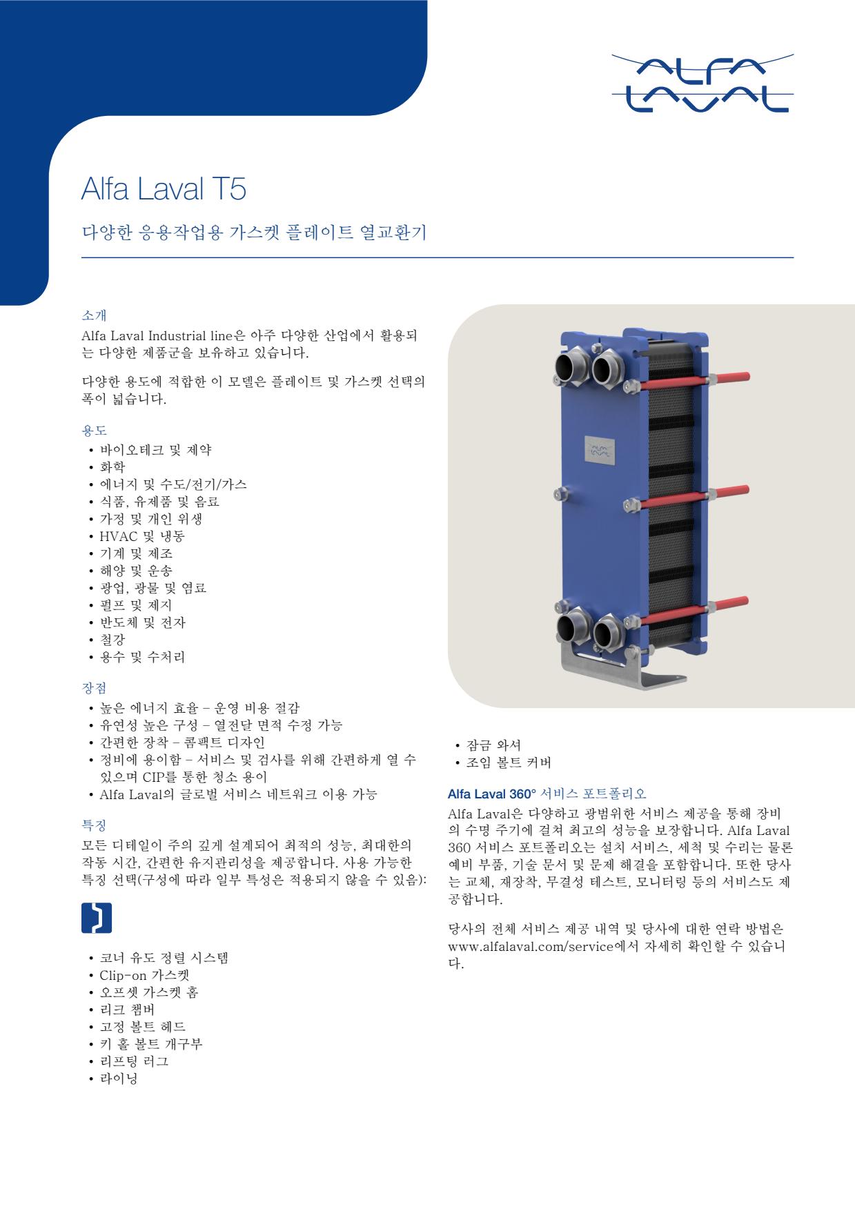
- Design Pressure M-Line
- >10 bar (145 psi)
- Marine Engine Room Modelle
- T6 (DN60, 800 kW) bis T35 (DN350, 35.000 kW)
- Marine FSRU Modelle
- TS45, T45, T50 (DN450-500, 45.000-55.000 kW)
- Temperaturbereich Standard
- 0–180°C (depending on model)
- FSRU Temperaturbereich
- -50 bis 150°C
- Plattentypen
- Chevron, Gemini Doppelwand, FlexFlow™
- M-Line (High Pressure Series: M3, M6, M10, M15)
- T-Series (Industrial: T2, T5, T6, T8, T10, T20, T25)
- AQ-Series (HVAC: AQ1, AQ2, AQ3, AQ4, AQ10)
- Marine Line (Engine Room: T6-T35; FSRU: TS45, T45, T50)
- Baseline (Competitive Line)
- Hygienic Line (Premium)
- Area: Gasket wear and embrittlementCheck: Inspect seals visually for cracks, hardening, swelling and discoloration; verify material compatibility with process fluids; check ClipGrip™ fastening. Aging symptoms and loss of elasticity are replacement indicators.
- Area: Clamping dimension and tightness (Tightening Dimension A)Check: Verify A-dimension per manufacturer specifications with caliper (metallic contact required). Keep bolts clean and lubricated. Avoid over-tightening. Perform regular re-tightening after operating hours. At too low A-dimension, pressure loss and leakage are to be expected.
- Area: Fouling and scale formation on plate surfacesCheck: Monitor pressure differential across heat exchanger (increase indicates deposits). Check heat duty versus design value. Optimize CIP intervals after performance audits. Deposits generate higher pump load (energy waste up to 8,000 kWh/year possible).
- Area: Plate corrosion and cracks / breakthroughsCheck: After disassembly, inspect plate surfaces for local measurements (pitting), cracks and perforation corrosion. Verify material compatibility with process fluid. Observe fatigue cracks especially at corners and transitions. When perforation occurs, plate is unrecoverable and must be replaced.
- Area: Pressure test and tightness inspectionCheck: After disassembly and cleaning, perform hydrostatic test per data sheet. Test pressure typically 1.5× operating pressure. Check external and internal leakage at all connections and plate edges. Document findings.
- Area: Plate sequence and alignment (5-point alignment)Check: After opening, verify plate sequence and honeycomb pattern (corrected chevron patterns must alternate). Activate/validate 5-point alignment system for larger units. Offset or misplacement leads to short-circuiting and reduced heat duty.
Type-universal inspection points for Alfa Laval Gasketed Plate Heat Exchangers (GPHE) (Alfa Laval, 2026-06). Per-model specs not auto-populated.
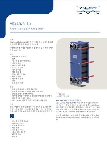
- Design Pressure M-Line
- >10 bar (145 psi)
- Marine Engine Room Modelle
- T6 (DN60, 800 kW) bis T35 (DN350, 35.000 kW)
- Marine FSRU Modelle
- TS45, T45, T50 (DN450-500, 45.000-55.000 kW)
- Temperaturbereich Standard
- 0–180°C (depending on model)
- FSRU Temperaturbereich
- -50 bis 150°C
- Plattentypen
- Chevron, Gemini Doppelwand, FlexFlow™
- M-Line (High Pressure Series: M3, M6, M10, M15)
- T-Series (Industrial: T2, T5, T6, T8, T10, T20, T25)
- AQ-Series (HVAC: AQ1, AQ2, AQ3, AQ4, AQ10)
- Marine Line (Engine Room: T6-T35; FSRU: TS45, T45, T50)
- Baseline (Competitive Line)
- Hygienic Line (Premium)
- Area: Gasket wear and embrittlementCheck: Inspect seals visually for cracks, hardening, swelling and discoloration; verify material compatibility with process fluids; check ClipGrip™ fastening. Aging symptoms and loss of elasticity are replacement indicators.
- Area: Clamping dimension and tightness (Tightening Dimension A)Check: Verify A-dimension per manufacturer specifications with caliper (metallic contact required). Keep bolts clean and lubricated. Avoid over-tightening. Perform regular re-tightening after operating hours. At too low A-dimension, pressure loss and leakage are to be expected.
- Area: Fouling and scale formation on plate surfacesCheck: Monitor pressure differential across heat exchanger (increase indicates deposits). Check heat duty versus design value. Optimize CIP intervals after performance audits. Deposits generate higher pump load (energy waste up to 8,000 kWh/year possible).
- Area: Plate corrosion and cracks / breakthroughsCheck: After disassembly, inspect plate surfaces for local measurements (pitting), cracks and perforation corrosion. Verify material compatibility with process fluid. Observe fatigue cracks especially at corners and transitions. When perforation occurs, plate is unrecoverable and must be replaced.
- Area: Pressure test and tightness inspectionCheck: After disassembly and cleaning, perform hydrostatic test per data sheet. Test pressure typically 1.5× operating pressure. Check external and internal leakage at all connections and plate edges. Document findings.
- Area: Plate sequence and alignment (5-point alignment)Check: After opening, verify plate sequence and honeycomb pattern (corrected chevron patterns must alternate). Activate/validate 5-point alignment system for larger units. Offset or misplacement leads to short-circuiting and reduced heat duty.
Type-universal inspection points for Alfa Laval Gasketed Plate Heat Exchangers (GPHE) (Alfa Laval, 2026-06). Per-model specs not auto-populated.
- Design Pressure M-Line
- >10 bar (145 psi)
- Marine Engine Room Modelle
- T6 (DN60, 800 kW) bis T35 (DN350, 35.000 kW)
- Marine FSRU Modelle
- TS45, T45, T50 (DN450-500, 45.000-55.000 kW)
- Temperaturbereich Standard
- 0–180°C (depending on model)
- FSRU Temperaturbereich
- -50 bis 150°C
- Plattentypen
- Chevron, Gemini Doppelwand, FlexFlow™
- M-Line (High Pressure Series: M3, M6, M10, M15)
- T-Series (Industrial: T2, T5, T6, T8, T10, T20, T25)
- AQ-Series (HVAC: AQ1, AQ2, AQ3, AQ4, AQ10)
- Marine Line (Engine Room: T6-T35; FSRU: TS45, T45, T50)
- Baseline (Competitive Line)
- Hygienic Line (Premium)
- Area: Gasket wear and embrittlementCheck: Inspect seals visually for cracks, hardening, swelling and discoloration; verify material compatibility with process fluids; check ClipGrip™ fastening. Aging symptoms and loss of elasticity are replacement indicators.
- Area: Clamping dimension and tightness (Tightening Dimension A)Check: Verify A-dimension per manufacturer specifications with caliper (metallic contact required). Keep bolts clean and lubricated. Avoid over-tightening. Perform regular re-tightening after operating hours. At too low A-dimension, pressure loss and leakage are to be expected.
- Area: Fouling and scale formation on plate surfacesCheck: Monitor pressure differential across heat exchanger (increase indicates deposits). Check heat duty versus design value. Optimize CIP intervals after performance audits. Deposits generate higher pump load (energy waste up to 8,000 kWh/year possible).
- Area: Plate corrosion and cracks / breakthroughsCheck: After disassembly, inspect plate surfaces for local measurements (pitting), cracks and perforation corrosion. Verify material compatibility with process fluid. Observe fatigue cracks especially at corners and transitions. When perforation occurs, plate is unrecoverable and must be replaced.
- Area: Pressure test and tightness inspectionCheck: After disassembly and cleaning, perform hydrostatic test per data sheet. Test pressure typically 1.5× operating pressure. Check external and internal leakage at all connections and plate edges. Document findings.
- Area: Plate sequence and alignment (5-point alignment)Check: After opening, verify plate sequence and honeycomb pattern (corrected chevron patterns must alternate). Activate/validate 5-point alignment system for larger units. Offset or misplacement leads to short-circuiting and reduced heat duty.
Type-universal inspection points for Alfa Laval Gasketed Plate Heat Exchangers (GPHE) (Alfa Laval, 2026-06). Per-model specs not auto-populated.
- Design Pressure M-Line
- >10 bar (145 psi)
- Marine Engine Room Modelle
- T6 (DN60, 800 kW) bis T35 (DN350, 35.000 kW)
- Marine FSRU Modelle
- TS45, T45, T50 (DN450-500, 45.000-55.000 kW)
- Temperaturbereich Standard
- 0–180°C (depending on model)
- FSRU Temperaturbereich
- -50 bis 150°C
- Plattentypen
- Chevron, Gemini Doppelwand, FlexFlow™
- M-Line (High Pressure Series: M3, M6, M10, M15)
- T-Series (Industrial: T2, T5, T6, T8, T10, T20, T25)
- AQ-Series (HVAC: AQ1, AQ2, AQ3, AQ4, AQ10)
- Marine Line (Engine Room: T6-T35; FSRU: TS45, T45, T50)
- Baseline (Competitive Line)
- Hygienic Line (Premium)
- Area: Gasket wear and embrittlementCheck: Inspect seals visually for cracks, hardening, swelling and discoloration; verify material compatibility with process fluids; check ClipGrip™ fastening. Aging symptoms and loss of elasticity are replacement indicators.
- Area: Clamping dimension and tightness (Tightening Dimension A)Check: Verify A-dimension per manufacturer specifications with caliper (metallic contact required). Keep bolts clean and lubricated. Avoid over-tightening. Perform regular re-tightening after operating hours. At too low A-dimension, pressure loss and leakage are to be expected.
- Area: Fouling and scale formation on plate surfacesCheck: Monitor pressure differential across heat exchanger (increase indicates deposits). Check heat duty versus design value. Optimize CIP intervals after performance audits. Deposits generate higher pump load (energy waste up to 8,000 kWh/year possible).
- Area: Plate corrosion and cracks / breakthroughsCheck: After disassembly, inspect plate surfaces for local measurements (pitting), cracks and perforation corrosion. Verify material compatibility with process fluid. Observe fatigue cracks especially at corners and transitions. When perforation occurs, plate is unrecoverable and must be replaced.
- Area: Pressure test and tightness inspectionCheck: After disassembly and cleaning, perform hydrostatic test per data sheet. Test pressure typically 1.5× operating pressure. Check external and internal leakage at all connections and plate edges. Document findings.
- Area: Plate sequence and alignment (5-point alignment)Check: After opening, verify plate sequence and honeycomb pattern (corrected chevron patterns must alternate). Activate/validate 5-point alignment system for larger units. Offset or misplacement leads to short-circuiting and reduced heat duty.
Type-universal inspection points for Alfa Laval Gasketed Plate Heat Exchangers (GPHE) (Alfa Laval, 2026-06). Per-model specs not auto-populated.
- Design Pressure M-Line
- >10 bar (145 psi)
- Marine Engine Room Modelle
- T6 (DN60, 800 kW) bis T35 (DN350, 35.000 kW)
- Marine FSRU Modelle
- TS45, T45, T50 (DN450-500, 45.000-55.000 kW)
- Temperaturbereich Standard
- 0–180°C (depending on model)
- FSRU Temperaturbereich
- -50 bis 150°C
- Plattentypen
- Chevron, Gemini Doppelwand, FlexFlow™
- M-Line (High Pressure Series: M3, M6, M10, M15)
- T-Series (Industrial: T2, T5, T6, T8, T10, T20, T25)
- AQ-Series (HVAC: AQ1, AQ2, AQ3, AQ4, AQ10)
- Marine Line (Engine Room: T6-T35; FSRU: TS45, T45, T50)
- Baseline (Competitive Line)
- Hygienic Line (Premium)
- Area: Gasket wear and embrittlementCheck: Inspect seals visually for cracks, hardening, swelling and discoloration; verify material compatibility with process fluids; check ClipGrip™ fastening. Aging symptoms and loss of elasticity are replacement indicators.
- Area: Clamping dimension and tightness (Tightening Dimension A)Check: Verify A-dimension per manufacturer specifications with caliper (metallic contact required). Keep bolts clean and lubricated. Avoid over-tightening. Perform regular re-tightening after operating hours. At too low A-dimension, pressure loss and leakage are to be expected.
- Area: Fouling and scale formation on plate surfacesCheck: Monitor pressure differential across heat exchanger (increase indicates deposits). Check heat duty versus design value. Optimize CIP intervals after performance audits. Deposits generate higher pump load (energy waste up to 8,000 kWh/year possible).
- Area: Plate corrosion and cracks / breakthroughsCheck: After disassembly, inspect plate surfaces for local measurements (pitting), cracks and perforation corrosion. Verify material compatibility with process fluid. Observe fatigue cracks especially at corners and transitions. When perforation occurs, plate is unrecoverable and must be replaced.
- Area: Pressure test and tightness inspectionCheck: After disassembly and cleaning, perform hydrostatic test per data sheet. Test pressure typically 1.5× operating pressure. Check external and internal leakage at all connections and plate edges. Document findings.
- Area: Plate sequence and alignment (5-point alignment)Check: After opening, verify plate sequence and honeycomb pattern (corrected chevron patterns must alternate). Activate/validate 5-point alignment system for larger units. Offset or misplacement leads to short-circuiting and reduced heat duty.
Type-universal inspection points for Alfa Laval Gasketed Plate Heat Exchangers (GPHE) (Alfa Laval, 2026-06). Per-model specs not auto-populated.
- Design Pressure M-Line
- >10 bar (145 psi)
- Marine Engine Room Modelle
- T6 (DN60, 800 kW) bis T35 (DN350, 35.000 kW)
- Marine FSRU Modelle
- TS45, T45, T50 (DN450-500, 45.000-55.000 kW)
- Temperaturbereich Standard
- 0–180°C (depending on model)
- FSRU Temperaturbereich
- -50 bis 150°C
- Plattentypen
- Chevron, Gemini Doppelwand, FlexFlow™
- M-Line (High Pressure Series: M3, M6, M10, M15)
- T-Series (Industrial: T2, T5, T6, T8, T10, T20, T25)
- AQ-Series (HVAC: AQ1, AQ2, AQ3, AQ4, AQ10)
- Marine Line (Engine Room: T6-T35; FSRU: TS45, T45, T50)
- Baseline (Competitive Line)
- Hygienic Line (Premium)
- Area: Gasket wear and embrittlementCheck: Inspect seals visually for cracks, hardening, swelling and discoloration; verify material compatibility with process fluids; check ClipGrip™ fastening. Aging symptoms and loss of elasticity are replacement indicators.
- Area: Clamping dimension and tightness (Tightening Dimension A)Check: Verify A-dimension per manufacturer specifications with caliper (metallic contact required). Keep bolts clean and lubricated. Avoid over-tightening. Perform regular re-tightening after operating hours. At too low A-dimension, pressure loss and leakage are to be expected.
- Area: Fouling and scale formation on plate surfacesCheck: Monitor pressure differential across heat exchanger (increase indicates deposits). Check heat duty versus design value. Optimize CIP intervals after performance audits. Deposits generate higher pump load (energy waste up to 8,000 kWh/year possible).
- Area: Plate corrosion and cracks / breakthroughsCheck: After disassembly, inspect plate surfaces for local measurements (pitting), cracks and perforation corrosion. Verify material compatibility with process fluid. Observe fatigue cracks especially at corners and transitions. When perforation occurs, plate is unrecoverable and must be replaced.
- Area: Pressure test and tightness inspectionCheck: After disassembly and cleaning, perform hydrostatic test per data sheet. Test pressure typically 1.5× operating pressure. Check external and internal leakage at all connections and plate edges. Document findings.
- Area: Plate sequence and alignment (5-point alignment)Check: After opening, verify plate sequence and honeycomb pattern (corrected chevron patterns must alternate). Activate/validate 5-point alignment system for larger units. Offset or misplacement leads to short-circuiting and reduced heat duty.
Type-universal inspection points for Alfa Laval Gasketed Plate Heat Exchangers (GPHE) (Alfa Laval, 2026-06). Per-model specs not auto-populated.
- Design Pressure M-Line
- >10 bar (145 psi)
- Marine Engine Room Modelle
- T6 (DN60, 800 kW) bis T35 (DN350, 35.000 kW)
- Marine FSRU Modelle
- TS45, T45, T50 (DN450-500, 45.000-55.000 kW)
- Temperaturbereich Standard
- 0–180°C (depending on model)
- FSRU Temperaturbereich
- -50 bis 150°C
- Plattentypen
- Chevron, Gemini Doppelwand, FlexFlow™
- M-Line (High Pressure Series: M3, M6, M10, M15)
- T-Series (Industrial: T2, T5, T6, T8, T10, T20, T25)
- AQ-Series (HVAC: AQ1, AQ2, AQ3, AQ4, AQ10)
- Marine Line (Engine Room: T6-T35; FSRU: TS45, T45, T50)
- Baseline (Competitive Line)
- Hygienic Line (Premium)
- Area: Gasket wear and embrittlementCheck: Inspect seals visually for cracks, hardening, swelling and discoloration; verify material compatibility with process fluids; check ClipGrip™ fastening. Aging symptoms and loss of elasticity are replacement indicators.
- Area: Clamping dimension and tightness (Tightening Dimension A)Check: Verify A-dimension per manufacturer specifications with caliper (metallic contact required). Keep bolts clean and lubricated. Avoid over-tightening. Perform regular re-tightening after operating hours. At too low A-dimension, pressure loss and leakage are to be expected.
- Area: Fouling and scale formation on plate surfacesCheck: Monitor pressure differential across heat exchanger (increase indicates deposits). Check heat duty versus design value. Optimize CIP intervals after performance audits. Deposits generate higher pump load (energy waste up to 8,000 kWh/year possible).
- Area: Plate corrosion and cracks / breakthroughsCheck: After disassembly, inspect plate surfaces for local measurements (pitting), cracks and perforation corrosion. Verify material compatibility with process fluid. Observe fatigue cracks especially at corners and transitions. When perforation occurs, plate is unrecoverable and must be replaced.
- Area: Pressure test and tightness inspectionCheck: After disassembly and cleaning, perform hydrostatic test per data sheet. Test pressure typically 1.5× operating pressure. Check external and internal leakage at all connections and plate edges. Document findings.
- Area: Plate sequence and alignment (5-point alignment)Check: After opening, verify plate sequence and honeycomb pattern (corrected chevron patterns must alternate). Activate/validate 5-point alignment system for larger units. Offset or misplacement leads to short-circuiting and reduced heat duty.
Type-universal inspection points for Alfa Laval Gasketed Plate Heat Exchangers (GPHE) (Alfa Laval, 2026-06). Per-model specs not auto-populated.
- Design Pressure M-Line
- >10 bar (145 psi)
- Marine Engine Room Modelle
- T6 (DN60, 800 kW) bis T35 (DN350, 35.000 kW)
- Marine FSRU Modelle
- TS45, T45, T50 (DN450-500, 45.000-55.000 kW)
- Temperaturbereich Standard
- 0–180°C (depending on model)
- FSRU Temperaturbereich
- -50 bis 150°C
- Plattentypen
- Chevron, Gemini Doppelwand, FlexFlow™
- M-Line (High Pressure Series: M3, M6, M10, M15)
- T-Series (Industrial: T2, T5, T6, T8, T10, T20, T25)
- AQ-Series (HVAC: AQ1, AQ2, AQ3, AQ4, AQ10)
- Marine Line (Engine Room: T6-T35; FSRU: TS45, T45, T50)
- Baseline (Competitive Line)
- Hygienic Line (Premium)
- Area: Gasket wear and embrittlementCheck: Inspect seals visually for cracks, hardening, swelling and discoloration; verify material compatibility with process fluids; check ClipGrip™ fastening. Aging symptoms and loss of elasticity are replacement indicators.
- Area: Clamping dimension and tightness (Tightening Dimension A)Check: Verify A-dimension per manufacturer specifications with caliper (metallic contact required). Keep bolts clean and lubricated. Avoid over-tightening. Perform regular re-tightening after operating hours. At too low A-dimension, pressure loss and leakage are to be expected.
- Area: Fouling and scale formation on plate surfacesCheck: Monitor pressure differential across heat exchanger (increase indicates deposits). Check heat duty versus design value. Optimize CIP intervals after performance audits. Deposits generate higher pump load (energy waste up to 8,000 kWh/year possible).
- Area: Plate corrosion and cracks / breakthroughsCheck: After disassembly, inspect plate surfaces for local measurements (pitting), cracks and perforation corrosion. Verify material compatibility with process fluid. Observe fatigue cracks especially at corners and transitions. When perforation occurs, plate is unrecoverable and must be replaced.
- Area: Pressure test and tightness inspectionCheck: After disassembly and cleaning, perform hydrostatic test per data sheet. Test pressure typically 1.5× operating pressure. Check external and internal leakage at all connections and plate edges. Document findings.
- Area: Plate sequence and alignment (5-point alignment)Check: After opening, verify plate sequence and honeycomb pattern (corrected chevron patterns must alternate). Activate/validate 5-point alignment system for larger units. Offset or misplacement leads to short-circuiting and reduced heat duty.
Type-universal inspection points for Alfa Laval Gasketed Plate Heat Exchangers (GPHE) (Alfa Laval, 2026-06). Per-model specs not auto-populated.
-facing-left_medium.webp)
- Design Pressure M-Line
- >10 bar (145 psi)
- Marine Engine Room Modelle
- T6 (DN60, 800 kW) bis T35 (DN350, 35.000 kW)
- Marine FSRU Modelle
- TS45, T45, T50 (DN450-500, 45.000-55.000 kW)
- Temperaturbereich Standard
- 0–180°C (depending on model)
- FSRU Temperaturbereich
- -50 bis 150°C
- Plattentypen
- Chevron, Gemini Doppelwand, FlexFlow™
- M-Line (High Pressure Series: M3, M6, M10, M15)
- T-Series (Industrial: T2, T5, T6, T8, T10, T20, T25)
- AQ-Series (HVAC: AQ1, AQ2, AQ3, AQ4, AQ10)
- Marine Line (Engine Room: T6-T35; FSRU: TS45, T45, T50)
- Baseline (Competitive Line)
- Hygienic Line (Premium)
- Area: Gasket wear and embrittlementCheck: Inspect seals visually for cracks, hardening, swelling and discoloration; verify material compatibility with process fluids; check ClipGrip™ fastening. Aging symptoms and loss of elasticity are replacement indicators.
- Area: Clamping dimension and tightness (Tightening Dimension A)Check: Verify A-dimension per manufacturer specifications with caliper (metallic contact required). Keep bolts clean and lubricated. Avoid over-tightening. Perform regular re-tightening after operating hours. At too low A-dimension, pressure loss and leakage are to be expected.
- Area: Fouling and scale formation on plate surfacesCheck: Monitor pressure differential across heat exchanger (increase indicates deposits). Check heat duty versus design value. Optimize CIP intervals after performance audits. Deposits generate higher pump load (energy waste up to 8,000 kWh/year possible).
- Area: Plate corrosion and cracks / breakthroughsCheck: After disassembly, inspect plate surfaces for local measurements (pitting), cracks and perforation corrosion. Verify material compatibility with process fluid. Observe fatigue cracks especially at corners and transitions. When perforation occurs, plate is unrecoverable and must be replaced.
- Area: Pressure test and tightness inspectionCheck: After disassembly and cleaning, perform hydrostatic test per data sheet. Test pressure typically 1.5× operating pressure. Check external and internal leakage at all connections and plate edges. Document findings.
- Area: Plate sequence and alignment (5-point alignment)Check: After opening, verify plate sequence and honeycomb pattern (corrected chevron patterns must alternate). Activate/validate 5-point alignment system for larger units. Offset or misplacement leads to short-circuiting and reduced heat duty.
Type-universal inspection points for Alfa Laval Gasketed Plate Heat Exchangers (GPHE) (Alfa Laval, 2026-06). Per-model specs not auto-populated.
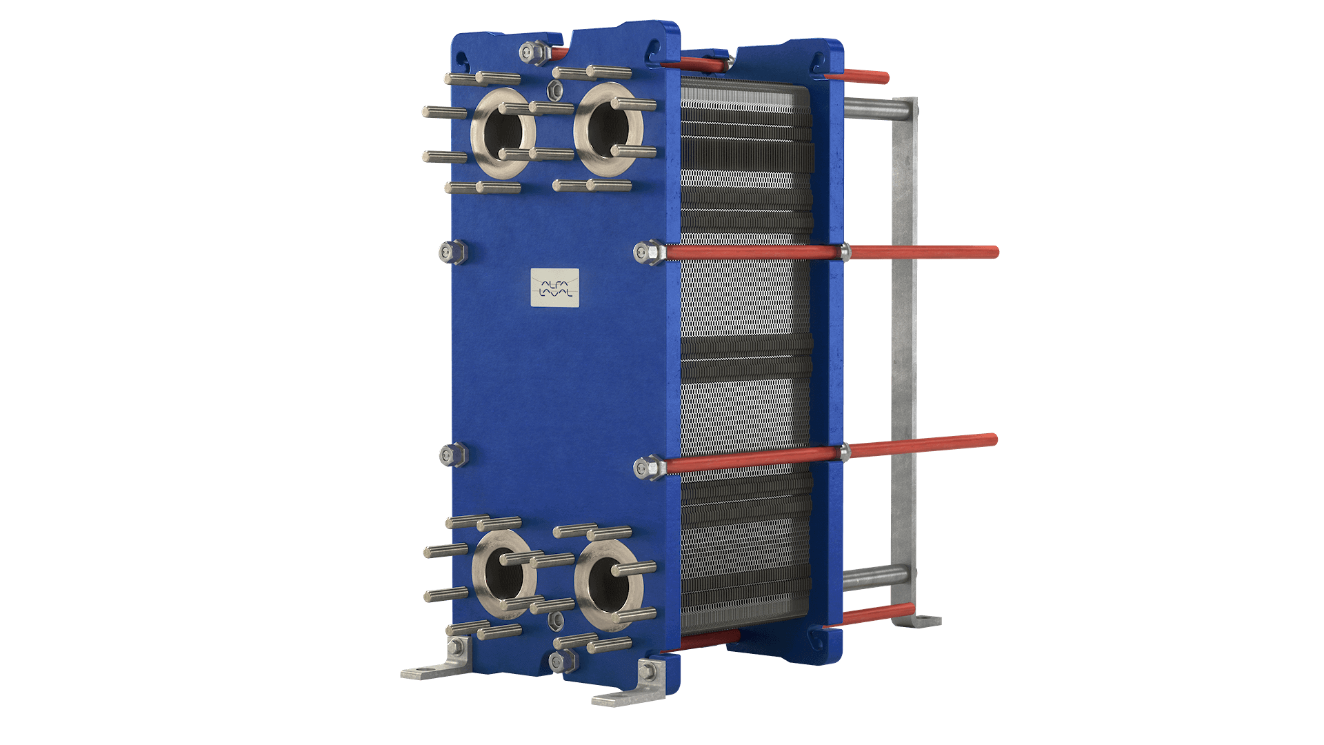
- Design Pressure M-Line
- >10 bar (145 psi)
- Marine Engine Room Modelle
- T6 (DN60, 800 kW) bis T35 (DN350, 35.000 kW)
- Marine FSRU Modelle
- TS45, T45, T50 (DN450-500, 45.000-55.000 kW)
- Temperaturbereich Standard
- 0–180°C (depending on model)
- FSRU Temperaturbereich
- -50 bis 150°C
- Plattentypen
- Chevron, Gemini Doppelwand, FlexFlow™
- M-Line (High Pressure Series: M3, M6, M10, M15)
- T-Series (Industrial: T2, T5, T6, T8, T10, T20, T25)
- AQ-Series (HVAC: AQ1, AQ2, AQ3, AQ4, AQ10)
- Marine Line (Engine Room: T6-T35; FSRU: TS45, T45, T50)
- Baseline (Competitive Line)
- Hygienic Line (Premium)
- Area: Gasket wear and embrittlementCheck: Inspect seals visually for cracks, hardening, swelling and discoloration; verify material compatibility with process fluids; check ClipGrip™ fastening. Aging symptoms and loss of elasticity are replacement indicators.
- Area: Clamping dimension and tightness (Tightening Dimension A)Check: Verify A-dimension per manufacturer specifications with caliper (metallic contact required). Keep bolts clean and lubricated. Avoid over-tightening. Perform regular re-tightening after operating hours. At too low A-dimension, pressure loss and leakage are to be expected.
- Area: Fouling and scale formation on plate surfacesCheck: Monitor pressure differential across heat exchanger (increase indicates deposits). Check heat duty versus design value. Optimize CIP intervals after performance audits. Deposits generate higher pump load (energy waste up to 8,000 kWh/year possible).
- Area: Plate corrosion and cracks / breakthroughsCheck: After disassembly, inspect plate surfaces for local measurements (pitting), cracks and perforation corrosion. Verify material compatibility with process fluid. Observe fatigue cracks especially at corners and transitions. When perforation occurs, plate is unrecoverable and must be replaced.
- Area: Pressure test and tightness inspectionCheck: After disassembly and cleaning, perform hydrostatic test per data sheet. Test pressure typically 1.5× operating pressure. Check external and internal leakage at all connections and plate edges. Document findings.
- Area: Plate sequence and alignment (5-point alignment)Check: After opening, verify plate sequence and honeycomb pattern (corrected chevron patterns must alternate). Activate/validate 5-point alignment system for larger units. Offset or misplacement leads to short-circuiting and reduced heat duty.
Type-universal inspection points for Alfa Laval Gasketed Plate Heat Exchangers (GPHE) (Alfa Laval, 2026-06). Per-model specs not auto-populated.
- Design Pressure M-Line
- >10 bar (145 psi)
- Marine Engine Room Modelle
- T6 (DN60, 800 kW) bis T35 (DN350, 35.000 kW)
- Marine FSRU Modelle
- TS45, T45, T50 (DN450-500, 45.000-55.000 kW)
- Temperaturbereich Standard
- 0–180°C (depending on model)
- FSRU Temperaturbereich
- -50 bis 150°C
- Plattentypen
- Chevron, Gemini Doppelwand, FlexFlow™
- M-Line (High Pressure Series: M3, M6, M10, M15)
- T-Series (Industrial: T2, T5, T6, T8, T10, T20, T25)
- AQ-Series (HVAC: AQ1, AQ2, AQ3, AQ4, AQ10)
- Marine Line (Engine Room: T6-T35; FSRU: TS45, T45, T50)
- Baseline (Competitive Line)
- Hygienic Line (Premium)
- Area: Gasket wear and embrittlementCheck: Inspect seals visually for cracks, hardening, swelling and discoloration; verify material compatibility with process fluids; check ClipGrip™ fastening. Aging symptoms and loss of elasticity are replacement indicators.
- Area: Clamping dimension and tightness (Tightening Dimension A)Check: Verify A-dimension per manufacturer specifications with caliper (metallic contact required). Keep bolts clean and lubricated. Avoid over-tightening. Perform regular re-tightening after operating hours. At too low A-dimension, pressure loss and leakage are to be expected.
- Area: Fouling and scale formation on plate surfacesCheck: Monitor pressure differential across heat exchanger (increase indicates deposits). Check heat duty versus design value. Optimize CIP intervals after performance audits. Deposits generate higher pump load (energy waste up to 8,000 kWh/year possible).
- Area: Plate corrosion and cracks / breakthroughsCheck: After disassembly, inspect plate surfaces for local measurements (pitting), cracks and perforation corrosion. Verify material compatibility with process fluid. Observe fatigue cracks especially at corners and transitions. When perforation occurs, plate is unrecoverable and must be replaced.
- Area: Pressure test and tightness inspectionCheck: After disassembly and cleaning, perform hydrostatic test per data sheet. Test pressure typically 1.5× operating pressure. Check external and internal leakage at all connections and plate edges. Document findings.
- Area: Plate sequence and alignment (5-point alignment)Check: After opening, verify plate sequence and honeycomb pattern (corrected chevron patterns must alternate). Activate/validate 5-point alignment system for larger units. Offset or misplacement leads to short-circuiting and reduced heat duty.
Type-universal inspection points for Alfa Laval Gasketed Plate Heat Exchangers (GPHE) (Alfa Laval, 2026-06). Per-model specs not auto-populated.
- Design Pressure M-Line
- >10 bar (145 psi)
- Marine Engine Room Modelle
- T6 (DN60, 800 kW) bis T35 (DN350, 35.000 kW)
- Marine FSRU Modelle
- TS45, T45, T50 (DN450-500, 45.000-55.000 kW)
- Temperaturbereich Standard
- 0–180°C (depending on model)
- FSRU Temperaturbereich
- -50 bis 150°C
- Plattentypen
- Chevron, Gemini Doppelwand, FlexFlow™
- M-Line (High Pressure Series: M3, M6, M10, M15)
- T-Series (Industrial: T2, T5, T6, T8, T10, T20, T25)
- AQ-Series (HVAC: AQ1, AQ2, AQ3, AQ4, AQ10)
- Marine Line (Engine Room: T6-T35; FSRU: TS45, T45, T50)
- Baseline (Competitive Line)
- Hygienic Line (Premium)
- Area: Gasket wear and embrittlementCheck: Inspect seals visually for cracks, hardening, swelling and discoloration; verify material compatibility with process fluids; check ClipGrip™ fastening. Aging symptoms and loss of elasticity are replacement indicators.
- Area: Clamping dimension and tightness (Tightening Dimension A)Check: Verify A-dimension per manufacturer specifications with caliper (metallic contact required). Keep bolts clean and lubricated. Avoid over-tightening. Perform regular re-tightening after operating hours. At too low A-dimension, pressure loss and leakage are to be expected.
- Area: Fouling and scale formation on plate surfacesCheck: Monitor pressure differential across heat exchanger (increase indicates deposits). Check heat duty versus design value. Optimize CIP intervals after performance audits. Deposits generate higher pump load (energy waste up to 8,000 kWh/year possible).
- Area: Plate corrosion and cracks / breakthroughsCheck: After disassembly, inspect plate surfaces for local measurements (pitting), cracks and perforation corrosion. Verify material compatibility with process fluid. Observe fatigue cracks especially at corners and transitions. When perforation occurs, plate is unrecoverable and must be replaced.
- Area: Pressure test and tightness inspectionCheck: After disassembly and cleaning, perform hydrostatic test per data sheet. Test pressure typically 1.5× operating pressure. Check external and internal leakage at all connections and plate edges. Document findings.
- Area: Plate sequence and alignment (5-point alignment)Check: After opening, verify plate sequence and honeycomb pattern (corrected chevron patterns must alternate). Activate/validate 5-point alignment system for larger units. Offset or misplacement leads to short-circuiting and reduced heat duty.
Type-universal inspection points for Alfa Laval Gasketed Plate Heat Exchangers (GPHE) (Alfa Laval, 2026-06). Per-model specs not auto-populated.
- Design Pressure M-Line
- >10 bar (145 psi)
- Marine Engine Room Modelle
- T6 (DN60, 800 kW) bis T35 (DN350, 35.000 kW)
- Marine FSRU Modelle
- TS45, T45, T50 (DN450-500, 45.000-55.000 kW)
- Temperaturbereich Standard
- 0–180°C (depending on model)
- FSRU Temperaturbereich
- -50 bis 150°C
- Plattentypen
- Chevron, Gemini Doppelwand, FlexFlow™
- M-Line (High Pressure Series: M3, M6, M10, M15)
- T-Series (Industrial: T2, T5, T6, T8, T10, T20, T25)
- AQ-Series (HVAC: AQ1, AQ2, AQ3, AQ4, AQ10)
- Marine Line (Engine Room: T6-T35; FSRU: TS45, T45, T50)
- Baseline (Competitive Line)
- Hygienic Line (Premium)
- Area: Gasket wear and embrittlementCheck: Inspect seals visually for cracks, hardening, swelling and discoloration; verify material compatibility with process fluids; check ClipGrip™ fastening. Aging symptoms and loss of elasticity are replacement indicators.
- Area: Clamping dimension and tightness (Tightening Dimension A)Check: Verify A-dimension per manufacturer specifications with caliper (metallic contact required). Keep bolts clean and lubricated. Avoid over-tightening. Perform regular re-tightening after operating hours. At too low A-dimension, pressure loss and leakage are to be expected.
- Area: Fouling and scale formation on plate surfacesCheck: Monitor pressure differential across heat exchanger (increase indicates deposits). Check heat duty versus design value. Optimize CIP intervals after performance audits. Deposits generate higher pump load (energy waste up to 8,000 kWh/year possible).
- Area: Plate corrosion and cracks / breakthroughsCheck: After disassembly, inspect plate surfaces for local measurements (pitting), cracks and perforation corrosion. Verify material compatibility with process fluid. Observe fatigue cracks especially at corners and transitions. When perforation occurs, plate is unrecoverable and must be replaced.
- Area: Pressure test and tightness inspectionCheck: After disassembly and cleaning, perform hydrostatic test per data sheet. Test pressure typically 1.5× operating pressure. Check external and internal leakage at all connections and plate edges. Document findings.
- Area: Plate sequence and alignment (5-point alignment)Check: After opening, verify plate sequence and honeycomb pattern (corrected chevron patterns must alternate). Activate/validate 5-point alignment system for larger units. Offset or misplacement leads to short-circuiting and reduced heat duty.
Type-universal inspection points for Alfa Laval Gasketed Plate Heat Exchangers (GPHE) (Alfa Laval, 2026-06). Per-model specs not auto-populated.
- Design Pressure M-Line
- >10 bar (145 psi)
- Marine Engine Room Modelle
- T6 (DN60, 800 kW) bis T35 (DN350, 35.000 kW)
- Marine FSRU Modelle
- TS45, T45, T50 (DN450-500, 45.000-55.000 kW)
- Temperaturbereich Standard
- 0–180°C (depending on model)
- FSRU Temperaturbereich
- -50 bis 150°C
- Plattentypen
- Chevron, Gemini Doppelwand, FlexFlow™
- M-Line (High Pressure Series: M3, M6, M10, M15)
- T-Series (Industrial: T2, T5, T6, T8, T10, T20, T25)
- AQ-Series (HVAC: AQ1, AQ2, AQ3, AQ4, AQ10)
- Marine Line (Engine Room: T6-T35; FSRU: TS45, T45, T50)
- Baseline (Competitive Line)
- Hygienic Line (Premium)
- Area: Gasket wear and embrittlementCheck: Inspect seals visually for cracks, hardening, swelling and discoloration; verify material compatibility with process fluids; check ClipGrip™ fastening. Aging symptoms and loss of elasticity are replacement indicators.
- Area: Clamping dimension and tightness (Tightening Dimension A)Check: Verify A-dimension per manufacturer specifications with caliper (metallic contact required). Keep bolts clean and lubricated. Avoid over-tightening. Perform regular re-tightening after operating hours. At too low A-dimension, pressure loss and leakage are to be expected.
- Area: Fouling and scale formation on plate surfacesCheck: Monitor pressure differential across heat exchanger (increase indicates deposits). Check heat duty versus design value. Optimize CIP intervals after performance audits. Deposits generate higher pump load (energy waste up to 8,000 kWh/year possible).
- Area: Plate corrosion and cracks / breakthroughsCheck: After disassembly, inspect plate surfaces for local measurements (pitting), cracks and perforation corrosion. Verify material compatibility with process fluid. Observe fatigue cracks especially at corners and transitions. When perforation occurs, plate is unrecoverable and must be replaced.
- Area: Pressure test and tightness inspectionCheck: After disassembly and cleaning, perform hydrostatic test per data sheet. Test pressure typically 1.5× operating pressure. Check external and internal leakage at all connections and plate edges. Document findings.
- Area: Plate sequence and alignment (5-point alignment)Check: After opening, verify plate sequence and honeycomb pattern (corrected chevron patterns must alternate). Activate/validate 5-point alignment system for larger units. Offset or misplacement leads to short-circuiting and reduced heat duty.
Type-universal inspection points for Alfa Laval Gasketed Plate Heat Exchangers (GPHE) (Alfa Laval, 2026-06). Per-model specs not auto-populated.
- Design Pressure M-Line
- >10 bar (145 psi)
- Marine Engine Room Modelle
- T6 (DN60, 800 kW) bis T35 (DN350, 35.000 kW)
- Marine FSRU Modelle
- TS45, T45, T50 (DN450-500, 45.000-55.000 kW)
- Temperaturbereich Standard
- 0–180°C (depending on model)
- FSRU Temperaturbereich
- -50 bis 150°C
- Plattentypen
- Chevron, Gemini Doppelwand, FlexFlow™
- M-Line (High Pressure Series: M3, M6, M10, M15)
- T-Series (Industrial: T2, T5, T6, T8, T10, T20, T25)
- AQ-Series (HVAC: AQ1, AQ2, AQ3, AQ4, AQ10)
- Marine Line (Engine Room: T6-T35; FSRU: TS45, T45, T50)
- Baseline (Competitive Line)
- Hygienic Line (Premium)
- Area: Gasket wear and embrittlementCheck: Inspect seals visually for cracks, hardening, swelling and discoloration; verify material compatibility with process fluids; check ClipGrip™ fastening. Aging symptoms and loss of elasticity are replacement indicators.
- Area: Clamping dimension and tightness (Tightening Dimension A)Check: Verify A-dimension per manufacturer specifications with caliper (metallic contact required). Keep bolts clean and lubricated. Avoid over-tightening. Perform regular re-tightening after operating hours. At too low A-dimension, pressure loss and leakage are to be expected.
- Area: Fouling and scale formation on plate surfacesCheck: Monitor pressure differential across heat exchanger (increase indicates deposits). Check heat duty versus design value. Optimize CIP intervals after performance audits. Deposits generate higher pump load (energy waste up to 8,000 kWh/year possible).
- Area: Plate corrosion and cracks / breakthroughsCheck: After disassembly, inspect plate surfaces for local measurements (pitting), cracks and perforation corrosion. Verify material compatibility with process fluid. Observe fatigue cracks especially at corners and transitions. When perforation occurs, plate is unrecoverable and must be replaced.
- Area: Pressure test and tightness inspectionCheck: After disassembly and cleaning, perform hydrostatic test per data sheet. Test pressure typically 1.5× operating pressure. Check external and internal leakage at all connections and plate edges. Document findings.
- Area: Plate sequence and alignment (5-point alignment)Check: After opening, verify plate sequence and honeycomb pattern (corrected chevron patterns must alternate). Activate/validate 5-point alignment system for larger units. Offset or misplacement leads to short-circuiting and reduced heat duty.
Type-universal inspection points for Alfa Laval Gasketed Plate Heat Exchangers (GPHE) (Alfa Laval, 2026-06). Per-model specs not auto-populated.
- Design Pressure M-Line
- >10 bar (145 psi)
- Marine Engine Room Modelle
- T6 (DN60, 800 kW) bis T35 (DN350, 35.000 kW)
- Marine FSRU Modelle
- TS45, T45, T50 (DN450-500, 45.000-55.000 kW)
- Temperaturbereich Standard
- 0–180°C (depending on model)
- FSRU Temperaturbereich
- -50 bis 150°C
- Plattentypen
- Chevron, Gemini Doppelwand, FlexFlow™
- M-Line (High Pressure Series: M3, M6, M10, M15)
- T-Series (Industrial: T2, T5, T6, T8, T10, T20, T25)
- AQ-Series (HVAC: AQ1, AQ2, AQ3, AQ4, AQ10)
- Marine Line (Engine Room: T6-T35; FSRU: TS45, T45, T50)
- Baseline (Competitive Line)
- Hygienic Line (Premium)
- Area: Gasket wear and embrittlementCheck: Inspect seals visually for cracks, hardening, swelling and discoloration; verify material compatibility with process fluids; check ClipGrip™ fastening. Aging symptoms and loss of elasticity are replacement indicators.
- Area: Clamping dimension and tightness (Tightening Dimension A)Check: Verify A-dimension per manufacturer specifications with caliper (metallic contact required). Keep bolts clean and lubricated. Avoid over-tightening. Perform regular re-tightening after operating hours. At too low A-dimension, pressure loss and leakage are to be expected.
- Area: Fouling and scale formation on plate surfacesCheck: Monitor pressure differential across heat exchanger (increase indicates deposits). Check heat duty versus design value. Optimize CIP intervals after performance audits. Deposits generate higher pump load (energy waste up to 8,000 kWh/year possible).
- Area: Plate corrosion and cracks / breakthroughsCheck: After disassembly, inspect plate surfaces for local measurements (pitting), cracks and perforation corrosion. Verify material compatibility with process fluid. Observe fatigue cracks especially at corners and transitions. When perforation occurs, plate is unrecoverable and must be replaced.
- Area: Pressure test and tightness inspectionCheck: After disassembly and cleaning, perform hydrostatic test per data sheet. Test pressure typically 1.5× operating pressure. Check external and internal leakage at all connections and plate edges. Document findings.
- Area: Plate sequence and alignment (5-point alignment)Check: After opening, verify plate sequence and honeycomb pattern (corrected chevron patterns must alternate). Activate/validate 5-point alignment system for larger units. Offset or misplacement leads to short-circuiting and reduced heat duty.
Type-universal inspection points for Alfa Laval Gasketed Plate Heat Exchangers (GPHE) (Alfa Laval, 2026-06). Per-model specs not auto-populated.
- Design Pressure M-Line
- >10 bar (145 psi)
- Marine Engine Room Modelle
- T6 (DN60, 800 kW) bis T35 (DN350, 35.000 kW)
- Marine FSRU Modelle
- TS45, T45, T50 (DN450-500, 45.000-55.000 kW)
- Temperaturbereich Standard
- 0–180°C (depending on model)
- FSRU Temperaturbereich
- -50 bis 150°C
- Plattentypen
- Chevron, Gemini Doppelwand, FlexFlow™
- M-Line (High Pressure Series: M3, M6, M10, M15)
- T-Series (Industrial: T2, T5, T6, T8, T10, T20, T25)
- AQ-Series (HVAC: AQ1, AQ2, AQ3, AQ4, AQ10)
- Marine Line (Engine Room: T6-T35; FSRU: TS45, T45, T50)
- Baseline (Competitive Line)
- Hygienic Line (Premium)
- Area: Gasket wear and embrittlementCheck: Inspect seals visually for cracks, hardening, swelling and discoloration; verify material compatibility with process fluids; check ClipGrip™ fastening. Aging symptoms and loss of elasticity are replacement indicators.
- Area: Clamping dimension and tightness (Tightening Dimension A)Check: Verify A-dimension per manufacturer specifications with caliper (metallic contact required). Keep bolts clean and lubricated. Avoid over-tightening. Perform regular re-tightening after operating hours. At too low A-dimension, pressure loss and leakage are to be expected.
- Area: Fouling and scale formation on plate surfacesCheck: Monitor pressure differential across heat exchanger (increase indicates deposits). Check heat duty versus design value. Optimize CIP intervals after performance audits. Deposits generate higher pump load (energy waste up to 8,000 kWh/year possible).
- Area: Plate corrosion and cracks / breakthroughsCheck: After disassembly, inspect plate surfaces for local measurements (pitting), cracks and perforation corrosion. Verify material compatibility with process fluid. Observe fatigue cracks especially at corners and transitions. When perforation occurs, plate is unrecoverable and must be replaced.
- Area: Pressure test and tightness inspectionCheck: After disassembly and cleaning, perform hydrostatic test per data sheet. Test pressure typically 1.5× operating pressure. Check external and internal leakage at all connections and plate edges. Document findings.
- Area: Plate sequence and alignment (5-point alignment)Check: After opening, verify plate sequence and honeycomb pattern (corrected chevron patterns must alternate). Activate/validate 5-point alignment system for larger units. Offset or misplacement leads to short-circuiting and reduced heat duty.
Type-universal inspection points for Alfa Laval Gasketed Plate Heat Exchangers (GPHE) (Alfa Laval, 2026-06). Per-model specs not auto-populated.
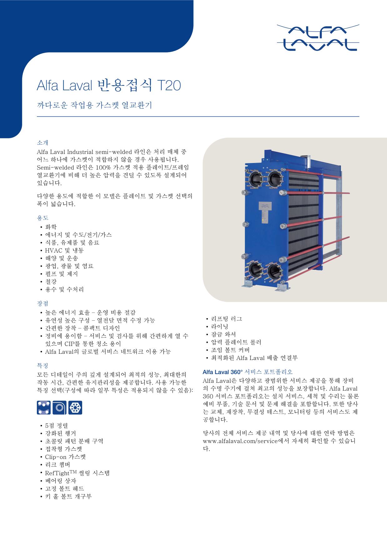
- Design Pressure M-Line
- >10 bar (145 psi)
- Marine Engine Room Modelle
- T6 (DN60, 800 kW) bis T35 (DN350, 35.000 kW)
- Marine FSRU Modelle
- TS45, T45, T50 (DN450-500, 45.000-55.000 kW)
- Temperaturbereich Standard
- 0–180°C (depending on model)
- FSRU Temperaturbereich
- -50 bis 150°C
- Plattentypen
- Chevron, Gemini Doppelwand, FlexFlow™
- M-Line (High Pressure Series: M3, M6, M10, M15)
- T-Series (Industrial: T2, T5, T6, T8, T10, T20, T25)
- AQ-Series (HVAC: AQ1, AQ2, AQ3, AQ4, AQ10)
- Marine Line (Engine Room: T6-T35; FSRU: TS45, T45, T50)
- Baseline (Competitive Line)
- Hygienic Line (Premium)
- Area: Gasket wear and embrittlementCheck: Inspect seals visually for cracks, hardening, swelling and discoloration; verify material compatibility with process fluids; check ClipGrip™ fastening. Aging symptoms and loss of elasticity are replacement indicators.
- Area: Clamping dimension and tightness (Tightening Dimension A)Check: Verify A-dimension per manufacturer specifications with caliper (metallic contact required). Keep bolts clean and lubricated. Avoid over-tightening. Perform regular re-tightening after operating hours. At too low A-dimension, pressure loss and leakage are to be expected.
- Area: Fouling and scale formation on plate surfacesCheck: Monitor pressure differential across heat exchanger (increase indicates deposits). Check heat duty versus design value. Optimize CIP intervals after performance audits. Deposits generate higher pump load (energy waste up to 8,000 kWh/year possible).
- Area: Plate corrosion and cracks / breakthroughsCheck: After disassembly, inspect plate surfaces for local measurements (pitting), cracks and perforation corrosion. Verify material compatibility with process fluid. Observe fatigue cracks especially at corners and transitions. When perforation occurs, plate is unrecoverable and must be replaced.
- Area: Pressure test and tightness inspectionCheck: After disassembly and cleaning, perform hydrostatic test per data sheet. Test pressure typically 1.5× operating pressure. Check external and internal leakage at all connections and plate edges. Document findings.
- Area: Plate sequence and alignment (5-point alignment)Check: After opening, verify plate sequence and honeycomb pattern (corrected chevron patterns must alternate). Activate/validate 5-point alignment system for larger units. Offset or misplacement leads to short-circuiting and reduced heat duty.
Type-universal inspection points for Alfa Laval Gasketed Plate Heat Exchangers (GPHE) (Alfa Laval, 2026-06). Per-model specs not auto-populated.
- Design Pressure M-Line
- >10 bar (145 psi)
- Marine Engine Room Modelle
- T6 (DN60, 800 kW) bis T35 (DN350, 35.000 kW)
- Marine FSRU Modelle
- TS45, T45, T50 (DN450-500, 45.000-55.000 kW)
- Temperaturbereich Standard
- 0–180°C (depending on model)
- FSRU Temperaturbereich
- -50 bis 150°C
- Plattentypen
- Chevron, Gemini Doppelwand, FlexFlow™
- M-Line (High Pressure Series: M3, M6, M10, M15)
- T-Series (Industrial: T2, T5, T6, T8, T10, T20, T25)
- AQ-Series (HVAC: AQ1, AQ2, AQ3, AQ4, AQ10)
- Marine Line (Engine Room: T6-T35; FSRU: TS45, T45, T50)
- Baseline (Competitive Line)
- Hygienic Line (Premium)
- Area: Gasket wear and embrittlementCheck: Inspect seals visually for cracks, hardening, swelling and discoloration; verify material compatibility with process fluids; check ClipGrip™ fastening. Aging symptoms and loss of elasticity are replacement indicators.
- Area: Clamping dimension and tightness (Tightening Dimension A)Check: Verify A-dimension per manufacturer specifications with caliper (metallic contact required). Keep bolts clean and lubricated. Avoid over-tightening. Perform regular re-tightening after operating hours. At too low A-dimension, pressure loss and leakage are to be expected.
- Area: Fouling and scale formation on plate surfacesCheck: Monitor pressure differential across heat exchanger (increase indicates deposits). Check heat duty versus design value. Optimize CIP intervals after performance audits. Deposits generate higher pump load (energy waste up to 8,000 kWh/year possible).
- Area: Plate corrosion and cracks / breakthroughsCheck: After disassembly, inspect plate surfaces for local measurements (pitting), cracks and perforation corrosion. Verify material compatibility with process fluid. Observe fatigue cracks especially at corners and transitions. When perforation occurs, plate is unrecoverable and must be replaced.
- Area: Pressure test and tightness inspectionCheck: After disassembly and cleaning, perform hydrostatic test per data sheet. Test pressure typically 1.5× operating pressure. Check external and internal leakage at all connections and plate edges. Document findings.
- Area: Plate sequence and alignment (5-point alignment)Check: After opening, verify plate sequence and honeycomb pattern (corrected chevron patterns must alternate). Activate/validate 5-point alignment system for larger units. Offset or misplacement leads to short-circuiting and reduced heat duty.
Type-universal inspection points for Alfa Laval Gasketed Plate Heat Exchangers (GPHE) (Alfa Laval, 2026-06). Per-model specs not auto-populated.
- Design Pressure M-Line
- >10 bar (145 psi)
- Marine Engine Room Modelle
- T6 (DN60, 800 kW) bis T35 (DN350, 35.000 kW)
- Marine FSRU Modelle
- TS45, T45, T50 (DN450-500, 45.000-55.000 kW)
- Temperaturbereich Standard
- 0–180°C (depending on model)
- FSRU Temperaturbereich
- -50 bis 150°C
- Plattentypen
- Chevron, Gemini Doppelwand, FlexFlow™
- M-Line (High Pressure Series: M3, M6, M10, M15)
- T-Series (Industrial: T2, T5, T6, T8, T10, T20, T25)
- AQ-Series (HVAC: AQ1, AQ2, AQ3, AQ4, AQ10)
- Marine Line (Engine Room: T6-T35; FSRU: TS45, T45, T50)
- Baseline (Competitive Line)
- Hygienic Line (Premium)
- Area: Gasket wear and embrittlementCheck: Inspect seals visually for cracks, hardening, swelling and discoloration; verify material compatibility with process fluids; check ClipGrip™ fastening. Aging symptoms and loss of elasticity are replacement indicators.
- Area: Clamping dimension and tightness (Tightening Dimension A)Check: Verify A-dimension per manufacturer specifications with caliper (metallic contact required). Keep bolts clean and lubricated. Avoid over-tightening. Perform regular re-tightening after operating hours. At too low A-dimension, pressure loss and leakage are to be expected.
- Area: Fouling and scale formation on plate surfacesCheck: Monitor pressure differential across heat exchanger (increase indicates deposits). Check heat duty versus design value. Optimize CIP intervals after performance audits. Deposits generate higher pump load (energy waste up to 8,000 kWh/year possible).
- Area: Plate corrosion and cracks / breakthroughsCheck: After disassembly, inspect plate surfaces for local measurements (pitting), cracks and perforation corrosion. Verify material compatibility with process fluid. Observe fatigue cracks especially at corners and transitions. When perforation occurs, plate is unrecoverable and must be replaced.
- Area: Pressure test and tightness inspectionCheck: After disassembly and cleaning, perform hydrostatic test per data sheet. Test pressure typically 1.5× operating pressure. Check external and internal leakage at all connections and plate edges. Document findings.
- Area: Plate sequence and alignment (5-point alignment)Check: After opening, verify plate sequence and honeycomb pattern (corrected chevron patterns must alternate). Activate/validate 5-point alignment system for larger units. Offset or misplacement leads to short-circuiting and reduced heat duty.
Type-universal inspection points for Alfa Laval Gasketed Plate Heat Exchangers (GPHE) (Alfa Laval, 2026-06). Per-model specs not auto-populated.
- Design Pressure M-Line
- >10 bar (145 psi)
- Marine Engine Room Modelle
- T6 (DN60, 800 kW) bis T35 (DN350, 35.000 kW)
- Marine FSRU Modelle
- TS45, T45, T50 (DN450-500, 45.000-55.000 kW)
- Temperaturbereich Standard
- 0–180°C (depending on model)
- FSRU Temperaturbereich
- -50 bis 150°C
- Plattentypen
- Chevron, Gemini Doppelwand, FlexFlow™
- M-Line (High Pressure Series: M3, M6, M10, M15)
- T-Series (Industrial: T2, T5, T6, T8, T10, T20, T25)
- AQ-Series (HVAC: AQ1, AQ2, AQ3, AQ4, AQ10)
- Marine Line (Engine Room: T6-T35; FSRU: TS45, T45, T50)
- Baseline (Competitive Line)
- Hygienic Line (Premium)
- Area: Gasket wear and embrittlementCheck: Inspect seals visually for cracks, hardening, swelling and discoloration; verify material compatibility with process fluids; check ClipGrip™ fastening. Aging symptoms and loss of elasticity are replacement indicators.
- Area: Clamping dimension and tightness (Tightening Dimension A)Check: Verify A-dimension per manufacturer specifications with caliper (metallic contact required). Keep bolts clean and lubricated. Avoid over-tightening. Perform regular re-tightening after operating hours. At too low A-dimension, pressure loss and leakage are to be expected.
- Area: Fouling and scale formation on plate surfacesCheck: Monitor pressure differential across heat exchanger (increase indicates deposits). Check heat duty versus design value. Optimize CIP intervals after performance audits. Deposits generate higher pump load (energy waste up to 8,000 kWh/year possible).
- Area: Plate corrosion and cracks / breakthroughsCheck: After disassembly, inspect plate surfaces for local measurements (pitting), cracks and perforation corrosion. Verify material compatibility with process fluid. Observe fatigue cracks especially at corners and transitions. When perforation occurs, plate is unrecoverable and must be replaced.
- Area: Pressure test and tightness inspectionCheck: After disassembly and cleaning, perform hydrostatic test per data sheet. Test pressure typically 1.5× operating pressure. Check external and internal leakage at all connections and plate edges. Document findings.
- Area: Plate sequence and alignment (5-point alignment)Check: After opening, verify plate sequence and honeycomb pattern (corrected chevron patterns must alternate). Activate/validate 5-point alignment system for larger units. Offset or misplacement leads to short-circuiting and reduced heat duty.
Type-universal inspection points for Alfa Laval Gasketed Plate Heat Exchangers (GPHE) (Alfa Laval, 2026-06). Per-model specs not auto-populated.
- Design Pressure M-Line
- >10 bar (145 psi)
- Marine Engine Room Modelle
- T6 (DN60, 800 kW) bis T35 (DN350, 35.000 kW)
- Marine FSRU Modelle
- TS45, T45, T50 (DN450-500, 45.000-55.000 kW)
- Temperaturbereich Standard
- 0–180°C (depending on model)
- FSRU Temperaturbereich
- -50 bis 150°C
- Plattentypen
- Chevron, Gemini Doppelwand, FlexFlow™
- M-Line (High Pressure Series: M3, M6, M10, M15)
- T-Series (Industrial: T2, T5, T6, T8, T10, T20, T25)
- AQ-Series (HVAC: AQ1, AQ2, AQ3, AQ4, AQ10)
- Marine Line (Engine Room: T6-T35; FSRU: TS45, T45, T50)
- Baseline (Competitive Line)
- Hygienic Line (Premium)
- Area: Gasket wear and embrittlementCheck: Inspect seals visually for cracks, hardening, swelling and discoloration; verify material compatibility with process fluids; check ClipGrip™ fastening. Aging symptoms and loss of elasticity are replacement indicators.
- Area: Clamping dimension and tightness (Tightening Dimension A)Check: Verify A-dimension per manufacturer specifications with caliper (metallic contact required). Keep bolts clean and lubricated. Avoid over-tightening. Perform regular re-tightening after operating hours. At too low A-dimension, pressure loss and leakage are to be expected.
- Area: Fouling and scale formation on plate surfacesCheck: Monitor pressure differential across heat exchanger (increase indicates deposits). Check heat duty versus design value. Optimize CIP intervals after performance audits. Deposits generate higher pump load (energy waste up to 8,000 kWh/year possible).
- Area: Plate corrosion and cracks / breakthroughsCheck: After disassembly, inspect plate surfaces for local measurements (pitting), cracks and perforation corrosion. Verify material compatibility with process fluid. Observe fatigue cracks especially at corners and transitions. When perforation occurs, plate is unrecoverable and must be replaced.
- Area: Pressure test and tightness inspectionCheck: After disassembly and cleaning, perform hydrostatic test per data sheet. Test pressure typically 1.5× operating pressure. Check external and internal leakage at all connections and plate edges. Document findings.
- Area: Plate sequence and alignment (5-point alignment)Check: After opening, verify plate sequence and honeycomb pattern (corrected chevron patterns must alternate). Activate/validate 5-point alignment system for larger units. Offset or misplacement leads to short-circuiting and reduced heat duty.
Type-universal inspection points for Alfa Laval Gasketed Plate Heat Exchangers (GPHE) (Alfa Laval, 2026-06). Per-model specs not auto-populated.
- Design Pressure M-Line
- >10 bar (145 psi)
- Marine Engine Room Modelle
- T6 (DN60, 800 kW) bis T35 (DN350, 35.000 kW)
- Marine FSRU Modelle
- TS45, T45, T50 (DN450-500, 45.000-55.000 kW)
- Temperaturbereich Standard
- 0–180°C (depending on model)
- FSRU Temperaturbereich
- -50 bis 150°C
- Plattentypen
- Chevron, Gemini Doppelwand, FlexFlow™
- M-Line (High Pressure Series: M3, M6, M10, M15)
- T-Series (Industrial: T2, T5, T6, T8, T10, T20, T25)
- AQ-Series (HVAC: AQ1, AQ2, AQ3, AQ4, AQ10)
- Marine Line (Engine Room: T6-T35; FSRU: TS45, T45, T50)
- Baseline (Competitive Line)
- Hygienic Line (Premium)
- Area: Gasket wear and embrittlementCheck: Inspect seals visually for cracks, hardening, swelling and discoloration; verify material compatibility with process fluids; check ClipGrip™ fastening. Aging symptoms and loss of elasticity are replacement indicators.
- Area: Clamping dimension and tightness (Tightening Dimension A)Check: Verify A-dimension per manufacturer specifications with caliper (metallic contact required). Keep bolts clean and lubricated. Avoid over-tightening. Perform regular re-tightening after operating hours. At too low A-dimension, pressure loss and leakage are to be expected.
- Area: Fouling and scale formation on plate surfacesCheck: Monitor pressure differential across heat exchanger (increase indicates deposits). Check heat duty versus design value. Optimize CIP intervals after performance audits. Deposits generate higher pump load (energy waste up to 8,000 kWh/year possible).
- Area: Plate corrosion and cracks / breakthroughsCheck: After disassembly, inspect plate surfaces for local measurements (pitting), cracks and perforation corrosion. Verify material compatibility with process fluid. Observe fatigue cracks especially at corners and transitions. When perforation occurs, plate is unrecoverable and must be replaced.
- Area: Pressure test and tightness inspectionCheck: After disassembly and cleaning, perform hydrostatic test per data sheet. Test pressure typically 1.5× operating pressure. Check external and internal leakage at all connections and plate edges. Document findings.
- Area: Plate sequence and alignment (5-point alignment)Check: After opening, verify plate sequence and honeycomb pattern (corrected chevron patterns must alternate). Activate/validate 5-point alignment system for larger units. Offset or misplacement leads to short-circuiting and reduced heat duty.
Type-universal inspection points for Alfa Laval Gasketed Plate Heat Exchangers (GPHE) (Alfa Laval, 2026-06). Per-model specs not auto-populated.
- Design Pressure M-Line
- >10 bar (145 psi)
- Marine Engine Room Modelle
- T6 (DN60, 800 kW) bis T35 (DN350, 35.000 kW)
- Marine FSRU Modelle
- TS45, T45, T50 (DN450-500, 45.000-55.000 kW)
- Temperaturbereich Standard
- 0–180°C (depending on model)
- FSRU Temperaturbereich
- -50 bis 150°C
- Plattentypen
- Chevron, Gemini Doppelwand, FlexFlow™
- M-Line (High Pressure Series: M3, M6, M10, M15)
- T-Series (Industrial: T2, T5, T6, T8, T10, T20, T25)
- AQ-Series (HVAC: AQ1, AQ2, AQ3, AQ4, AQ10)
- Marine Line (Engine Room: T6-T35; FSRU: TS45, T45, T50)
- Baseline (Competitive Line)
- Hygienic Line (Premium)
- Area: Gasket wear and embrittlementCheck: Inspect seals visually for cracks, hardening, swelling and discoloration; verify material compatibility with process fluids; check ClipGrip™ fastening. Aging symptoms and loss of elasticity are replacement indicators.
- Area: Clamping dimension and tightness (Tightening Dimension A)Check: Verify A-dimension per manufacturer specifications with caliper (metallic contact required). Keep bolts clean and lubricated. Avoid over-tightening. Perform regular re-tightening after operating hours. At too low A-dimension, pressure loss and leakage are to be expected.
- Area: Fouling and scale formation on plate surfacesCheck: Monitor pressure differential across heat exchanger (increase indicates deposits). Check heat duty versus design value. Optimize CIP intervals after performance audits. Deposits generate higher pump load (energy waste up to 8,000 kWh/year possible).
- Area: Plate corrosion and cracks / breakthroughsCheck: After disassembly, inspect plate surfaces for local measurements (pitting), cracks and perforation corrosion. Verify material compatibility with process fluid. Observe fatigue cracks especially at corners and transitions. When perforation occurs, plate is unrecoverable and must be replaced.
- Area: Pressure test and tightness inspectionCheck: After disassembly and cleaning, perform hydrostatic test per data sheet. Test pressure typically 1.5× operating pressure. Check external and internal leakage at all connections and plate edges. Document findings.
- Area: Plate sequence and alignment (5-point alignment)Check: After opening, verify plate sequence and honeycomb pattern (corrected chevron patterns must alternate). Activate/validate 5-point alignment system for larger units. Offset or misplacement leads to short-circuiting and reduced heat duty.
Type-universal inspection points for Alfa Laval Gasketed Plate Heat Exchangers (GPHE) (Alfa Laval, 2026-06). Per-model specs not auto-populated.
- Design Pressure M-Line
- >10 bar (145 psi)
- Marine Engine Room Modelle
- T6 (DN60, 800 kW) bis T35 (DN350, 35.000 kW)
- Marine FSRU Modelle
- TS45, T45, T50 (DN450-500, 45.000-55.000 kW)
- Temperaturbereich Standard
- 0–180°C (depending on model)
- FSRU Temperaturbereich
- -50 bis 150°C
- Plattentypen
- Chevron, Gemini Doppelwand, FlexFlow™
- M-Line (High Pressure Series: M3, M6, M10, M15)
- T-Series (Industrial: T2, T5, T6, T8, T10, T20, T25)
- AQ-Series (HVAC: AQ1, AQ2, AQ3, AQ4, AQ10)
- Marine Line (Engine Room: T6-T35; FSRU: TS45, T45, T50)
- Baseline (Competitive Line)
- Hygienic Line (Premium)
- Area: Gasket wear and embrittlementCheck: Inspect seals visually for cracks, hardening, swelling and discoloration; verify material compatibility with process fluids; check ClipGrip™ fastening. Aging symptoms and loss of elasticity are replacement indicators.
- Area: Clamping dimension and tightness (Tightening Dimension A)Check: Verify A-dimension per manufacturer specifications with caliper (metallic contact required). Keep bolts clean and lubricated. Avoid over-tightening. Perform regular re-tightening after operating hours. At too low A-dimension, pressure loss and leakage are to be expected.
- Area: Fouling and scale formation on plate surfacesCheck: Monitor pressure differential across heat exchanger (increase indicates deposits). Check heat duty versus design value. Optimize CIP intervals after performance audits. Deposits generate higher pump load (energy waste up to 8,000 kWh/year possible).
- Area: Plate corrosion and cracks / breakthroughsCheck: After disassembly, inspect plate surfaces for local measurements (pitting), cracks and perforation corrosion. Verify material compatibility with process fluid. Observe fatigue cracks especially at corners and transitions. When perforation occurs, plate is unrecoverable and must be replaced.
- Area: Pressure test and tightness inspectionCheck: After disassembly and cleaning, perform hydrostatic test per data sheet. Test pressure typically 1.5× operating pressure. Check external and internal leakage at all connections and plate edges. Document findings.
- Area: Plate sequence and alignment (5-point alignment)Check: After opening, verify plate sequence and honeycomb pattern (corrected chevron patterns must alternate). Activate/validate 5-point alignment system for larger units. Offset or misplacement leads to short-circuiting and reduced heat duty.
Type-universal inspection points for Alfa Laval Gasketed Plate Heat Exchangers (GPHE) (Alfa Laval, 2026-06). Per-model specs not auto-populated.
- Design Pressure M-Line
- >10 bar (145 psi)
- Marine Engine Room Modelle
- T6 (DN60, 800 kW) bis T35 (DN350, 35.000 kW)
- Marine FSRU Modelle
- TS45, T45, T50 (DN450-500, 45.000-55.000 kW)
- Temperaturbereich Standard
- 0–180°C (depending on model)
- FSRU Temperaturbereich
- -50 bis 150°C
- Plattentypen
- Chevron, Gemini Doppelwand, FlexFlow™
- M-Line (High Pressure Series: M3, M6, M10, M15)
- T-Series (Industrial: T2, T5, T6, T8, T10, T20, T25)
- AQ-Series (HVAC: AQ1, AQ2, AQ3, AQ4, AQ10)
- Marine Line (Engine Room: T6-T35; FSRU: TS45, T45, T50)
- Baseline (Competitive Line)
- Hygienic Line (Premium)
- Area: Gasket wear and embrittlementCheck: Inspect seals visually for cracks, hardening, swelling and discoloration; verify material compatibility with process fluids; check ClipGrip™ fastening. Aging symptoms and loss of elasticity are replacement indicators.
- Area: Clamping dimension and tightness (Tightening Dimension A)Check: Verify A-dimension per manufacturer specifications with caliper (metallic contact required). Keep bolts clean and lubricated. Avoid over-tightening. Perform regular re-tightening after operating hours. At too low A-dimension, pressure loss and leakage are to be expected.
- Area: Fouling and scale formation on plate surfacesCheck: Monitor pressure differential across heat exchanger (increase indicates deposits). Check heat duty versus design value. Optimize CIP intervals after performance audits. Deposits generate higher pump load (energy waste up to 8,000 kWh/year possible).
- Area: Plate corrosion and cracks / breakthroughsCheck: After disassembly, inspect plate surfaces for local measurements (pitting), cracks and perforation corrosion. Verify material compatibility with process fluid. Observe fatigue cracks especially at corners and transitions. When perforation occurs, plate is unrecoverable and must be replaced.
- Area: Pressure test and tightness inspectionCheck: After disassembly and cleaning, perform hydrostatic test per data sheet. Test pressure typically 1.5× operating pressure. Check external and internal leakage at all connections and plate edges. Document findings.
- Area: Plate sequence and alignment (5-point alignment)Check: After opening, verify plate sequence and honeycomb pattern (corrected chevron patterns must alternate). Activate/validate 5-point alignment system for larger units. Offset or misplacement leads to short-circuiting and reduced heat duty.
Type-universal inspection points for Alfa Laval Gasketed Plate Heat Exchangers (GPHE) (Alfa Laval, 2026-06). Per-model specs not auto-populated.
- Design Pressure M-Line
- >10 bar (145 psi)
- Marine Engine Room Modelle
- T6 (DN60, 800 kW) bis T35 (DN350, 35.000 kW)
- Marine FSRU Modelle
- TS45, T45, T50 (DN450-500, 45.000-55.000 kW)
- Temperaturbereich Standard
- 0–180°C (depending on model)
- FSRU Temperaturbereich
- -50 bis 150°C
- Plattentypen
- Chevron, Gemini Doppelwand, FlexFlow™
- M-Line (High Pressure Series: M3, M6, M10, M15)
- T-Series (Industrial: T2, T5, T6, T8, T10, T20, T25)
- AQ-Series (HVAC: AQ1, AQ2, AQ3, AQ4, AQ10)
- Marine Line (Engine Room: T6-T35; FSRU: TS45, T45, T50)
- Baseline (Competitive Line)
- Hygienic Line (Premium)
- Area: Gasket wear and embrittlementCheck: Inspect seals visually for cracks, hardening, swelling and discoloration; verify material compatibility with process fluids; check ClipGrip™ fastening. Aging symptoms and loss of elasticity are replacement indicators.
- Area: Clamping dimension and tightness (Tightening Dimension A)Check: Verify A-dimension per manufacturer specifications with caliper (metallic contact required). Keep bolts clean and lubricated. Avoid over-tightening. Perform regular re-tightening after operating hours. At too low A-dimension, pressure loss and leakage are to be expected.
- Area: Fouling and scale formation on plate surfacesCheck: Monitor pressure differential across heat exchanger (increase indicates deposits). Check heat duty versus design value. Optimize CIP intervals after performance audits. Deposits generate higher pump load (energy waste up to 8,000 kWh/year possible).
- Area: Plate corrosion and cracks / breakthroughsCheck: After disassembly, inspect plate surfaces for local measurements (pitting), cracks and perforation corrosion. Verify material compatibility with process fluid. Observe fatigue cracks especially at corners and transitions. When perforation occurs, plate is unrecoverable and must be replaced.
- Area: Pressure test and tightness inspectionCheck: After disassembly and cleaning, perform hydrostatic test per data sheet. Test pressure typically 1.5× operating pressure. Check external and internal leakage at all connections and plate edges. Document findings.
- Area: Plate sequence and alignment (5-point alignment)Check: After opening, verify plate sequence and honeycomb pattern (corrected chevron patterns must alternate). Activate/validate 5-point alignment system for larger units. Offset or misplacement leads to short-circuiting and reduced heat duty.
Type-universal inspection points for Alfa Laval Gasketed Plate Heat Exchangers (GPHE) (Alfa Laval, 2026-06). Per-model specs not auto-populated.
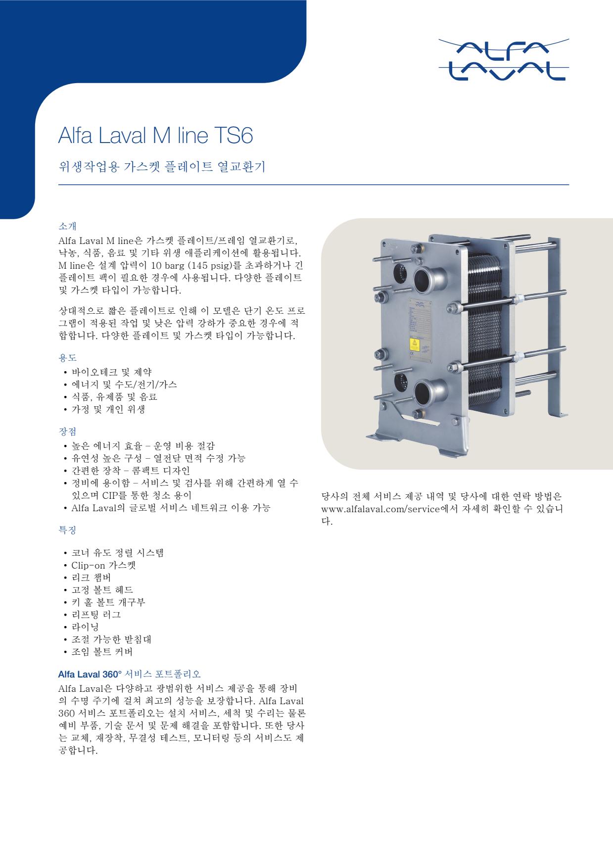
- Design Pressure M-Line
- >10 bar (145 psi)
- Marine Engine Room Modelle
- T6 (DN60, 800 kW) bis T35 (DN350, 35.000 kW)
- Marine FSRU Modelle
- TS45, T45, T50 (DN450-500, 45.000-55.000 kW)
- Temperaturbereich Standard
- 0–180°C (depending on model)
- FSRU Temperaturbereich
- -50 bis 150°C
- Plattentypen
- Chevron, Gemini Doppelwand, FlexFlow™
- M-Line (High Pressure Series: M3, M6, M10, M15)
- T-Series (Industrial: T2, T5, T6, T8, T10, T20, T25)
- AQ-Series (HVAC: AQ1, AQ2, AQ3, AQ4, AQ10)
- Marine Line (Engine Room: T6-T35; FSRU: TS45, T45, T50)
- Baseline (Competitive Line)
- Hygienic Line (Premium)
- Area: Gasket wear and embrittlementCheck: Inspect seals visually for cracks, hardening, swelling and discoloration; verify material compatibility with process fluids; check ClipGrip™ fastening. Aging symptoms and loss of elasticity are replacement indicators.
- Area: Clamping dimension and tightness (Tightening Dimension A)Check: Verify A-dimension per manufacturer specifications with caliper (metallic contact required). Keep bolts clean and lubricated. Avoid over-tightening. Perform regular re-tightening after operating hours. At too low A-dimension, pressure loss and leakage are to be expected.
- Area: Fouling and scale formation on plate surfacesCheck: Monitor pressure differential across heat exchanger (increase indicates deposits). Check heat duty versus design value. Optimize CIP intervals after performance audits. Deposits generate higher pump load (energy waste up to 8,000 kWh/year possible).
- Area: Plate corrosion and cracks / breakthroughsCheck: After disassembly, inspect plate surfaces for local measurements (pitting), cracks and perforation corrosion. Verify material compatibility with process fluid. Observe fatigue cracks especially at corners and transitions. When perforation occurs, plate is unrecoverable and must be replaced.
- Area: Pressure test and tightness inspectionCheck: After disassembly and cleaning, perform hydrostatic test per data sheet. Test pressure typically 1.5× operating pressure. Check external and internal leakage at all connections and plate edges. Document findings.
- Area: Plate sequence and alignment (5-point alignment)Check: After opening, verify plate sequence and honeycomb pattern (corrected chevron patterns must alternate). Activate/validate 5-point alignment system for larger units. Offset or misplacement leads to short-circuiting and reduced heat duty.
Type-universal inspection points for Alfa Laval Gasketed Plate Heat Exchangers (GPHE) (Alfa Laval, 2026-06). Per-model specs not auto-populated.
- Design Pressure M-Line
- >10 bar (145 psi)
- Marine Engine Room Modelle
- T6 (DN60, 800 kW) bis T35 (DN350, 35.000 kW)
- Marine FSRU Modelle
- TS45, T45, T50 (DN450-500, 45.000-55.000 kW)
- Temperaturbereich Standard
- 0–180°C (depending on model)
- FSRU Temperaturbereich
- -50 bis 150°C
- Plattentypen
- Chevron, Gemini Doppelwand, FlexFlow™
- M-Line (High Pressure Series: M3, M6, M10, M15)
- T-Series (Industrial: T2, T5, T6, T8, T10, T20, T25)
- AQ-Series (HVAC: AQ1, AQ2, AQ3, AQ4, AQ10)
- Marine Line (Engine Room: T6-T35; FSRU: TS45, T45, T50)
- Baseline (Competitive Line)
- Hygienic Line (Premium)
- Area: Gasket wear and embrittlementCheck: Inspect seals visually for cracks, hardening, swelling and discoloration; verify material compatibility with process fluids; check ClipGrip™ fastening. Aging symptoms and loss of elasticity are replacement indicators.
- Area: Clamping dimension and tightness (Tightening Dimension A)Check: Verify A-dimension per manufacturer specifications with caliper (metallic contact required). Keep bolts clean and lubricated. Avoid over-tightening. Perform regular re-tightening after operating hours. At too low A-dimension, pressure loss and leakage are to be expected.
- Area: Fouling and scale formation on plate surfacesCheck: Monitor pressure differential across heat exchanger (increase indicates deposits). Check heat duty versus design value. Optimize CIP intervals after performance audits. Deposits generate higher pump load (energy waste up to 8,000 kWh/year possible).
- Area: Plate corrosion and cracks / breakthroughsCheck: After disassembly, inspect plate surfaces for local measurements (pitting), cracks and perforation corrosion. Verify material compatibility with process fluid. Observe fatigue cracks especially at corners and transitions. When perforation occurs, plate is unrecoverable and must be replaced.
- Area: Pressure test and tightness inspectionCheck: After disassembly and cleaning, perform hydrostatic test per data sheet. Test pressure typically 1.5× operating pressure. Check external and internal leakage at all connections and plate edges. Document findings.
- Area: Plate sequence and alignment (5-point alignment)Check: After opening, verify plate sequence and honeycomb pattern (corrected chevron patterns must alternate). Activate/validate 5-point alignment system for larger units. Offset or misplacement leads to short-circuiting and reduced heat duty.
Type-universal inspection points for Alfa Laval Gasketed Plate Heat Exchangers (GPHE) (Alfa Laval, 2026-06). Per-model specs not auto-populated.
- Design Pressure M-Line
- >10 bar (145 psi)
- Marine Engine Room Modelle
- T6 (DN60, 800 kW) bis T35 (DN350, 35.000 kW)
- Marine FSRU Modelle
- TS45, T45, T50 (DN450-500, 45.000-55.000 kW)
- Temperaturbereich Standard
- 0–180°C (depending on model)
- FSRU Temperaturbereich
- -50 bis 150°C
- Plattentypen
- Chevron, Gemini Doppelwand, FlexFlow™
- M-Line (High Pressure Series: M3, M6, M10, M15)
- T-Series (Industrial: T2, T5, T6, T8, T10, T20, T25)
- AQ-Series (HVAC: AQ1, AQ2, AQ3, AQ4, AQ10)
- Marine Line (Engine Room: T6-T35; FSRU: TS45, T45, T50)
- Baseline (Competitive Line)
- Hygienic Line (Premium)
- Area: Gasket wear and embrittlementCheck: Inspect seals visually for cracks, hardening, swelling and discoloration; verify material compatibility with process fluids; check ClipGrip™ fastening. Aging symptoms and loss of elasticity are replacement indicators.
- Area: Clamping dimension and tightness (Tightening Dimension A)Check: Verify A-dimension per manufacturer specifications with caliper (metallic contact required). Keep bolts clean and lubricated. Avoid over-tightening. Perform regular re-tightening after operating hours. At too low A-dimension, pressure loss and leakage are to be expected.
- Area: Fouling and scale formation on plate surfacesCheck: Monitor pressure differential across heat exchanger (increase indicates deposits). Check heat duty versus design value. Optimize CIP intervals after performance audits. Deposits generate higher pump load (energy waste up to 8,000 kWh/year possible).
- Area: Plate corrosion and cracks / breakthroughsCheck: After disassembly, inspect plate surfaces for local measurements (pitting), cracks and perforation corrosion. Verify material compatibility with process fluid. Observe fatigue cracks especially at corners and transitions. When perforation occurs, plate is unrecoverable and must be replaced.
- Area: Pressure test and tightness inspectionCheck: After disassembly and cleaning, perform hydrostatic test per data sheet. Test pressure typically 1.5× operating pressure. Check external and internal leakage at all connections and plate edges. Document findings.
- Area: Plate sequence and alignment (5-point alignment)Check: After opening, verify plate sequence and honeycomb pattern (corrected chevron patterns must alternate). Activate/validate 5-point alignment system for larger units. Offset or misplacement leads to short-circuiting and reduced heat duty.
Type-universal inspection points for Alfa Laval Gasketed Plate Heat Exchangers (GPHE) (Alfa Laval, 2026-06). Per-model specs not auto-populated.
- Design Pressure M-Line
- >10 bar (145 psi)
- Marine Engine Room Modelle
- T6 (DN60, 800 kW) bis T35 (DN350, 35.000 kW)
- Marine FSRU Modelle
- TS45, T45, T50 (DN450-500, 45.000-55.000 kW)
- Temperaturbereich Standard
- 0–180°C (depending on model)
- FSRU Temperaturbereich
- -50 bis 150°C
- Plattentypen
- Chevron, Gemini Doppelwand, FlexFlow™
- M-Line (High Pressure Series: M3, M6, M10, M15)
- T-Series (Industrial: T2, T5, T6, T8, T10, T20, T25)
- AQ-Series (HVAC: AQ1, AQ2, AQ3, AQ4, AQ10)
- Marine Line (Engine Room: T6-T35; FSRU: TS45, T45, T50)
- Baseline (Competitive Line)
- Hygienic Line (Premium)
- Area: Gasket wear and embrittlementCheck: Inspect seals visually for cracks, hardening, swelling and discoloration; verify material compatibility with process fluids; check ClipGrip™ fastening. Aging symptoms and loss of elasticity are replacement indicators.
- Area: Clamping dimension and tightness (Tightening Dimension A)Check: Verify A-dimension per manufacturer specifications with caliper (metallic contact required). Keep bolts clean and lubricated. Avoid over-tightening. Perform regular re-tightening after operating hours. At too low A-dimension, pressure loss and leakage are to be expected.
- Area: Fouling and scale formation on plate surfacesCheck: Monitor pressure differential across heat exchanger (increase indicates deposits). Check heat duty versus design value. Optimize CIP intervals after performance audits. Deposits generate higher pump load (energy waste up to 8,000 kWh/year possible).
- Area: Plate corrosion and cracks / breakthroughsCheck: After disassembly, inspect plate surfaces for local measurements (pitting), cracks and perforation corrosion. Verify material compatibility with process fluid. Observe fatigue cracks especially at corners and transitions. When perforation occurs, plate is unrecoverable and must be replaced.
- Area: Pressure test and tightness inspectionCheck: After disassembly and cleaning, perform hydrostatic test per data sheet. Test pressure typically 1.5× operating pressure. Check external and internal leakage at all connections and plate edges. Document findings.
- Area: Plate sequence and alignment (5-point alignment)Check: After opening, verify plate sequence and honeycomb pattern (corrected chevron patterns must alternate). Activate/validate 5-point alignment system for larger units. Offset or misplacement leads to short-circuiting and reduced heat duty.
Type-universal inspection points for Alfa Laval Gasketed Plate Heat Exchangers (GPHE) (Alfa Laval, 2026-06). Per-model specs not auto-populated.
- Design Pressure M-Line
- >10 bar (145 psi)
- Marine Engine Room Modelle
- T6 (DN60, 800 kW) bis T35 (DN350, 35.000 kW)
- Marine FSRU Modelle
- TS45, T45, T50 (DN450-500, 45.000-55.000 kW)
- Temperaturbereich Standard
- 0–180°C (depending on model)
- FSRU Temperaturbereich
- -50 bis 150°C
- Plattentypen
- Chevron, Gemini Doppelwand, FlexFlow™
- M-Line (High Pressure Series: M3, M6, M10, M15)
- T-Series (Industrial: T2, T5, T6, T8, T10, T20, T25)
- AQ-Series (HVAC: AQ1, AQ2, AQ3, AQ4, AQ10)
- Marine Line (Engine Room: T6-T35; FSRU: TS45, T45, T50)
- Baseline (Competitive Line)
- Hygienic Line (Premium)
- Area: Gasket wear and embrittlementCheck: Inspect seals visually for cracks, hardening, swelling and discoloration; verify material compatibility with process fluids; check ClipGrip™ fastening. Aging symptoms and loss of elasticity are replacement indicators.
- Area: Clamping dimension and tightness (Tightening Dimension A)Check: Verify A-dimension per manufacturer specifications with caliper (metallic contact required). Keep bolts clean and lubricated. Avoid over-tightening. Perform regular re-tightening after operating hours. At too low A-dimension, pressure loss and leakage are to be expected.
- Area: Fouling and scale formation on plate surfacesCheck: Monitor pressure differential across heat exchanger (increase indicates deposits). Check heat duty versus design value. Optimize CIP intervals after performance audits. Deposits generate higher pump load (energy waste up to 8,000 kWh/year possible).
- Area: Plate corrosion and cracks / breakthroughsCheck: After disassembly, inspect plate surfaces for local measurements (pitting), cracks and perforation corrosion. Verify material compatibility with process fluid. Observe fatigue cracks especially at corners and transitions. When perforation occurs, plate is unrecoverable and must be replaced.
- Area: Pressure test and tightness inspectionCheck: After disassembly and cleaning, perform hydrostatic test per data sheet. Test pressure typically 1.5× operating pressure. Check external and internal leakage at all connections and plate edges. Document findings.
- Area: Plate sequence and alignment (5-point alignment)Check: After opening, verify plate sequence and honeycomb pattern (corrected chevron patterns must alternate). Activate/validate 5-point alignment system for larger units. Offset or misplacement leads to short-circuiting and reduced heat duty.
Type-universal inspection points for Alfa Laval Gasketed Plate Heat Exchangers (GPHE) (Alfa Laval, 2026-06). Per-model specs not auto-populated.
- Design Pressure M-Line
- >10 bar (145 psi)
- Marine Engine Room Modelle
- T6 (DN60, 800 kW) bis T35 (DN350, 35.000 kW)
- Marine FSRU Modelle
- TS45, T45, T50 (DN450-500, 45.000-55.000 kW)
- Temperaturbereich Standard
- 0–180°C (depending on model)
- FSRU Temperaturbereich
- -50 bis 150°C
- Plattentypen
- Chevron, Gemini Doppelwand, FlexFlow™
- M-Line (High Pressure Series: M3, M6, M10, M15)
- T-Series (Industrial: T2, T5, T6, T8, T10, T20, T25)
- AQ-Series (HVAC: AQ1, AQ2, AQ3, AQ4, AQ10)
- Marine Line (Engine Room: T6-T35; FSRU: TS45, T45, T50)
- Baseline (Competitive Line)
- Hygienic Line (Premium)
- Area: Gasket wear and embrittlementCheck: Inspect seals visually for cracks, hardening, swelling and discoloration; verify material compatibility with process fluids; check ClipGrip™ fastening. Aging symptoms and loss of elasticity are replacement indicators.
- Area: Clamping dimension and tightness (Tightening Dimension A)Check: Verify A-dimension per manufacturer specifications with caliper (metallic contact required). Keep bolts clean and lubricated. Avoid over-tightening. Perform regular re-tightening after operating hours. At too low A-dimension, pressure loss and leakage are to be expected.
- Area: Fouling and scale formation on plate surfacesCheck: Monitor pressure differential across heat exchanger (increase indicates deposits). Check heat duty versus design value. Optimize CIP intervals after performance audits. Deposits generate higher pump load (energy waste up to 8,000 kWh/year possible).
- Area: Plate corrosion and cracks / breakthroughsCheck: After disassembly, inspect plate surfaces for local measurements (pitting), cracks and perforation corrosion. Verify material compatibility with process fluid. Observe fatigue cracks especially at corners and transitions. When perforation occurs, plate is unrecoverable and must be replaced.
- Area: Pressure test and tightness inspectionCheck: After disassembly and cleaning, perform hydrostatic test per data sheet. Test pressure typically 1.5× operating pressure. Check external and internal leakage at all connections and plate edges. Document findings.
- Area: Plate sequence and alignment (5-point alignment)Check: After opening, verify plate sequence and honeycomb pattern (corrected chevron patterns must alternate). Activate/validate 5-point alignment system for larger units. Offset or misplacement leads to short-circuiting and reduced heat duty.
Type-universal inspection points for Alfa Laval Gasketed Plate Heat Exchangers (GPHE) (Alfa Laval, 2026-06). Per-model specs not auto-populated.
- Design Pressure M-Line
- >10 bar (145 psi)
- Marine Engine Room Modelle
- T6 (DN60, 800 kW) bis T35 (DN350, 35.000 kW)
- Marine FSRU Modelle
- TS45, T45, T50 (DN450-500, 45.000-55.000 kW)
- Temperaturbereich Standard
- 0–180°C (depending on model)
- FSRU Temperaturbereich
- -50 bis 150°C
- Plattentypen
- Chevron, Gemini Doppelwand, FlexFlow™
- M-Line (High Pressure Series: M3, M6, M10, M15)
- T-Series (Industrial: T2, T5, T6, T8, T10, T20, T25)
- AQ-Series (HVAC: AQ1, AQ2, AQ3, AQ4, AQ10)
- Marine Line (Engine Room: T6-T35; FSRU: TS45, T45, T50)
- Baseline (Competitive Line)
- Hygienic Line (Premium)
- Area: Gasket wear and embrittlementCheck: Inspect seals visually for cracks, hardening, swelling and discoloration; verify material compatibility with process fluids; check ClipGrip™ fastening. Aging symptoms and loss of elasticity are replacement indicators.
- Area: Clamping dimension and tightness (Tightening Dimension A)Check: Verify A-dimension per manufacturer specifications with caliper (metallic contact required). Keep bolts clean and lubricated. Avoid over-tightening. Perform regular re-tightening after operating hours. At too low A-dimension, pressure loss and leakage are to be expected.
- Area: Fouling and scale formation on plate surfacesCheck: Monitor pressure differential across heat exchanger (increase indicates deposits). Check heat duty versus design value. Optimize CIP intervals after performance audits. Deposits generate higher pump load (energy waste up to 8,000 kWh/year possible).
- Area: Plate corrosion and cracks / breakthroughsCheck: After disassembly, inspect plate surfaces for local measurements (pitting), cracks and perforation corrosion. Verify material compatibility with process fluid. Observe fatigue cracks especially at corners and transitions. When perforation occurs, plate is unrecoverable and must be replaced.
- Area: Pressure test and tightness inspectionCheck: After disassembly and cleaning, perform hydrostatic test per data sheet. Test pressure typically 1.5× operating pressure. Check external and internal leakage at all connections and plate edges. Document findings.
- Area: Plate sequence and alignment (5-point alignment)Check: After opening, verify plate sequence and honeycomb pattern (corrected chevron patterns must alternate). Activate/validate 5-point alignment system for larger units. Offset or misplacement leads to short-circuiting and reduced heat duty.
Type-universal inspection points for Alfa Laval Gasketed Plate Heat Exchangers (GPHE) (Alfa Laval, 2026-06). Per-model specs not auto-populated.
- Design Pressure M-Line
- >10 bar (145 psi)
- Marine Engine Room Modelle
- T6 (DN60, 800 kW) bis T35 (DN350, 35.000 kW)
- Marine FSRU Modelle
- TS45, T45, T50 (DN450-500, 45.000-55.000 kW)
- Temperaturbereich Standard
- 0–180°C (depending on model)
- FSRU Temperaturbereich
- -50 bis 150°C
- Plattentypen
- Chevron, Gemini Doppelwand, FlexFlow™
- M-Line (High Pressure Series: M3, M6, M10, M15)
- T-Series (Industrial: T2, T5, T6, T8, T10, T20, T25)
- AQ-Series (HVAC: AQ1, AQ2, AQ3, AQ4, AQ10)
- Marine Line (Engine Room: T6-T35; FSRU: TS45, T45, T50)
- Baseline (Competitive Line)
- Hygienic Line (Premium)
- Area: Gasket wear and embrittlementCheck: Inspect seals visually for cracks, hardening, swelling and discoloration; verify material compatibility with process fluids; check ClipGrip™ fastening. Aging symptoms and loss of elasticity are replacement indicators.
- Area: Clamping dimension and tightness (Tightening Dimension A)Check: Verify A-dimension per manufacturer specifications with caliper (metallic contact required). Keep bolts clean and lubricated. Avoid over-tightening. Perform regular re-tightening after operating hours. At too low A-dimension, pressure loss and leakage are to be expected.
- Area: Fouling and scale formation on plate surfacesCheck: Monitor pressure differential across heat exchanger (increase indicates deposits). Check heat duty versus design value. Optimize CIP intervals after performance audits. Deposits generate higher pump load (energy waste up to 8,000 kWh/year possible).
- Area: Plate corrosion and cracks / breakthroughsCheck: After disassembly, inspect plate surfaces for local measurements (pitting), cracks and perforation corrosion. Verify material compatibility with process fluid. Observe fatigue cracks especially at corners and transitions. When perforation occurs, plate is unrecoverable and must be replaced.
- Area: Pressure test and tightness inspectionCheck: After disassembly and cleaning, perform hydrostatic test per data sheet. Test pressure typically 1.5× operating pressure. Check external and internal leakage at all connections and plate edges. Document findings.
- Area: Plate sequence and alignment (5-point alignment)Check: After opening, verify plate sequence and honeycomb pattern (corrected chevron patterns must alternate). Activate/validate 5-point alignment system for larger units. Offset or misplacement leads to short-circuiting and reduced heat duty.
Type-universal inspection points for Alfa Laval Gasketed Plate Heat Exchangers (GPHE) (Alfa Laval, 2026-06). Per-model specs not auto-populated.
- Design Pressure M-Line
- >10 bar (145 psi)
- Marine Engine Room Modelle
- T6 (DN60, 800 kW) bis T35 (DN350, 35.000 kW)
- Marine FSRU Modelle
- TS45, T45, T50 (DN450-500, 45.000-55.000 kW)
- Temperaturbereich Standard
- 0–180°C (depending on model)
- FSRU Temperaturbereich
- -50 bis 150°C
- Plattentypen
- Chevron, Gemini Doppelwand, FlexFlow™
- M-Line (High Pressure Series: M3, M6, M10, M15)
- T-Series (Industrial: T2, T5, T6, T8, T10, T20, T25)
- AQ-Series (HVAC: AQ1, AQ2, AQ3, AQ4, AQ10)
- Marine Line (Engine Room: T6-T35; FSRU: TS45, T45, T50)
- Baseline (Competitive Line)
- Hygienic Line (Premium)
- Area: Gasket wear and embrittlementCheck: Inspect seals visually for cracks, hardening, swelling and discoloration; verify material compatibility with process fluids; check ClipGrip™ fastening. Aging symptoms and loss of elasticity are replacement indicators.
- Area: Clamping dimension and tightness (Tightening Dimension A)Check: Verify A-dimension per manufacturer specifications with caliper (metallic contact required). Keep bolts clean and lubricated. Avoid over-tightening. Perform regular re-tightening after operating hours. At too low A-dimension, pressure loss and leakage are to be expected.
- Area: Fouling and scale formation on plate surfacesCheck: Monitor pressure differential across heat exchanger (increase indicates deposits). Check heat duty versus design value. Optimize CIP intervals after performance audits. Deposits generate higher pump load (energy waste up to 8,000 kWh/year possible).
- Area: Plate corrosion and cracks / breakthroughsCheck: After disassembly, inspect plate surfaces for local measurements (pitting), cracks and perforation corrosion. Verify material compatibility with process fluid. Observe fatigue cracks especially at corners and transitions. When perforation occurs, plate is unrecoverable and must be replaced.
- Area: Pressure test and tightness inspectionCheck: After disassembly and cleaning, perform hydrostatic test per data sheet. Test pressure typically 1.5× operating pressure. Check external and internal leakage at all connections and plate edges. Document findings.
- Area: Plate sequence and alignment (5-point alignment)Check: After opening, verify plate sequence and honeycomb pattern (corrected chevron patterns must alternate). Activate/validate 5-point alignment system for larger units. Offset or misplacement leads to short-circuiting and reduced heat duty.
Type-universal inspection points for Alfa Laval Gasketed Plate Heat Exchangers (GPHE) (Alfa Laval, 2026-06). Per-model specs not auto-populated.
- Design Pressure M-Line
- >10 bar (145 psi)
- Marine Engine Room Modelle
- T6 (DN60, 800 kW) bis T35 (DN350, 35.000 kW)
- Marine FSRU Modelle
- TS45, T45, T50 (DN450-500, 45.000-55.000 kW)
- Temperaturbereich Standard
- 0–180°C (depending on model)
- FSRU Temperaturbereich
- -50 bis 150°C
- Plattentypen
- Chevron, Gemini Doppelwand, FlexFlow™
- M-Line (High Pressure Series: M3, M6, M10, M15)
- T-Series (Industrial: T2, T5, T6, T8, T10, T20, T25)
- AQ-Series (HVAC: AQ1, AQ2, AQ3, AQ4, AQ10)
- Marine Line (Engine Room: T6-T35; FSRU: TS45, T45, T50)
- Baseline (Competitive Line)
- Hygienic Line (Premium)
- Area: Gasket wear and embrittlementCheck: Inspect seals visually for cracks, hardening, swelling and discoloration; verify material compatibility with process fluids; check ClipGrip™ fastening. Aging symptoms and loss of elasticity are replacement indicators.
- Area: Clamping dimension and tightness (Tightening Dimension A)Check: Verify A-dimension per manufacturer specifications with caliper (metallic contact required). Keep bolts clean and lubricated. Avoid over-tightening. Perform regular re-tightening after operating hours. At too low A-dimension, pressure loss and leakage are to be expected.
- Area: Fouling and scale formation on plate surfacesCheck: Monitor pressure differential across heat exchanger (increase indicates deposits). Check heat duty versus design value. Optimize CIP intervals after performance audits. Deposits generate higher pump load (energy waste up to 8,000 kWh/year possible).
- Area: Plate corrosion and cracks / breakthroughsCheck: After disassembly, inspect plate surfaces for local measurements (pitting), cracks and perforation corrosion. Verify material compatibility with process fluid. Observe fatigue cracks especially at corners and transitions. When perforation occurs, plate is unrecoverable and must be replaced.
- Area: Pressure test and tightness inspectionCheck: After disassembly and cleaning, perform hydrostatic test per data sheet. Test pressure typically 1.5× operating pressure. Check external and internal leakage at all connections and plate edges. Document findings.
- Area: Plate sequence and alignment (5-point alignment)Check: After opening, verify plate sequence and honeycomb pattern (corrected chevron patterns must alternate). Activate/validate 5-point alignment system for larger units. Offset or misplacement leads to short-circuiting and reduced heat duty.
Type-universal inspection points for Alfa Laval Gasketed Plate Heat Exchangers (GPHE) (Alfa Laval, 2026-06). Per-model specs not auto-populated.
- Design Pressure M-Line
- >10 bar (145 psi)
- Marine Engine Room Modelle
- T6 (DN60, 800 kW) bis T35 (DN350, 35.000 kW)
- Marine FSRU Modelle
- TS45, T45, T50 (DN450-500, 45.000-55.000 kW)
- Temperaturbereich Standard
- 0–180°C (depending on model)
- FSRU Temperaturbereich
- -50 bis 150°C
- Plattentypen
- Chevron, Gemini Doppelwand, FlexFlow™
- M-Line (High Pressure Series: M3, M6, M10, M15)
- T-Series (Industrial: T2, T5, T6, T8, T10, T20, T25)
- AQ-Series (HVAC: AQ1, AQ2, AQ3, AQ4, AQ10)
- Marine Line (Engine Room: T6-T35; FSRU: TS45, T45, T50)
- Baseline (Competitive Line)
- Hygienic Line (Premium)
- Area: Gasket wear and embrittlementCheck: Inspect seals visually for cracks, hardening, swelling and discoloration; verify material compatibility with process fluids; check ClipGrip™ fastening. Aging symptoms and loss of elasticity are replacement indicators.
- Area: Clamping dimension and tightness (Tightening Dimension A)Check: Verify A-dimension per manufacturer specifications with caliper (metallic contact required). Keep bolts clean and lubricated. Avoid over-tightening. Perform regular re-tightening after operating hours. At too low A-dimension, pressure loss and leakage are to be expected.
- Area: Fouling and scale formation on plate surfacesCheck: Monitor pressure differential across heat exchanger (increase indicates deposits). Check heat duty versus design value. Optimize CIP intervals after performance audits. Deposits generate higher pump load (energy waste up to 8,000 kWh/year possible).
- Area: Plate corrosion and cracks / breakthroughsCheck: After disassembly, inspect plate surfaces for local measurements (pitting), cracks and perforation corrosion. Verify material compatibility with process fluid. Observe fatigue cracks especially at corners and transitions. When perforation occurs, plate is unrecoverable and must be replaced.
- Area: Pressure test and tightness inspectionCheck: After disassembly and cleaning, perform hydrostatic test per data sheet. Test pressure typically 1.5× operating pressure. Check external and internal leakage at all connections and plate edges. Document findings.
- Area: Plate sequence and alignment (5-point alignment)Check: After opening, verify plate sequence and honeycomb pattern (corrected chevron patterns must alternate). Activate/validate 5-point alignment system for larger units. Offset or misplacement leads to short-circuiting and reduced heat duty.
Type-universal inspection points for Alfa Laval Gasketed Plate Heat Exchangers (GPHE) (Alfa Laval, 2026-06). Per-model specs not auto-populated.

- Design Pressure M-Line
- >10 bar (145 psi)
- Marine Engine Room Modelle
- T6 (DN60, 800 kW) bis T35 (DN350, 35.000 kW)
- Marine FSRU Modelle
- TS45, T45, T50 (DN450-500, 45.000-55.000 kW)
- Temperaturbereich Standard
- 0–180°C (depending on model)
- FSRU Temperaturbereich
- -50 bis 150°C
- Plattentypen
- Chevron, Gemini Doppelwand, FlexFlow™
- M-Line (High Pressure Series: M3, M6, M10, M15)
- T-Series (Industrial: T2, T5, T6, T8, T10, T20, T25)
- AQ-Series (HVAC: AQ1, AQ2, AQ3, AQ4, AQ10)
- Marine Line (Engine Room: T6-T35; FSRU: TS45, T45, T50)
- Baseline (Competitive Line)
- Hygienic Line (Premium)
- Area: Gasket wear and embrittlementCheck: Inspect seals visually for cracks, hardening, swelling and discoloration; verify material compatibility with process fluids; check ClipGrip™ fastening. Aging symptoms and loss of elasticity are replacement indicators.
- Area: Clamping dimension and tightness (Tightening Dimension A)Check: Verify A-dimension per manufacturer specifications with caliper (metallic contact required). Keep bolts clean and lubricated. Avoid over-tightening. Perform regular re-tightening after operating hours. At too low A-dimension, pressure loss and leakage are to be expected.
- Area: Fouling and scale formation on plate surfacesCheck: Monitor pressure differential across heat exchanger (increase indicates deposits). Check heat duty versus design value. Optimize CIP intervals after performance audits. Deposits generate higher pump load (energy waste up to 8,000 kWh/year possible).
- Area: Plate corrosion and cracks / breakthroughsCheck: After disassembly, inspect plate surfaces for local measurements (pitting), cracks and perforation corrosion. Verify material compatibility with process fluid. Observe fatigue cracks especially at corners and transitions. When perforation occurs, plate is unrecoverable and must be replaced.
- Area: Pressure test and tightness inspectionCheck: After disassembly and cleaning, perform hydrostatic test per data sheet. Test pressure typically 1.5× operating pressure. Check external and internal leakage at all connections and plate edges. Document findings.
- Area: Plate sequence and alignment (5-point alignment)Check: After opening, verify plate sequence and honeycomb pattern (corrected chevron patterns must alternate). Activate/validate 5-point alignment system for larger units. Offset or misplacement leads to short-circuiting and reduced heat duty.
Type-universal inspection points for Alfa Laval Gasketed Plate Heat Exchangers (GPHE) (Alfa Laval, 2026-06). Per-model specs not auto-populated.
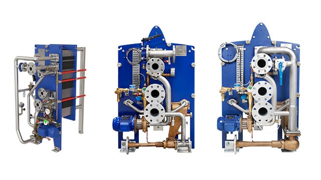
- Design Pressure M-Line
- >10 bar (145 psi)
- Marine Engine Room Modelle
- T6 (DN60, 800 kW) bis T35 (DN350, 35.000 kW)
- Marine FSRU Modelle
- TS45, T45, T50 (DN450-500, 45.000-55.000 kW)
- Temperaturbereich Standard
- 0–180°C (depending on model)
- FSRU Temperaturbereich
- -50 bis 150°C
- Plattentypen
- Chevron, Gemini Doppelwand, FlexFlow™
- M-Line (High Pressure Series: M3, M6, M10, M15)
- T-Series (Industrial: T2, T5, T6, T8, T10, T20, T25)
- AQ-Series (HVAC: AQ1, AQ2, AQ3, AQ4, AQ10)
- Marine Line (Engine Room: T6-T35; FSRU: TS45, T45, T50)
- Baseline (Competitive Line)
- Hygienic Line (Premium)
- Area: Gasket wear and embrittlementCheck: Inspect seals visually for cracks, hardening, swelling and discoloration; verify material compatibility with process fluids; check ClipGrip™ fastening. Aging symptoms and loss of elasticity are replacement indicators.
- Area: Clamping dimension and tightness (Tightening Dimension A)Check: Verify A-dimension per manufacturer specifications with caliper (metallic contact required). Keep bolts clean and lubricated. Avoid over-tightening. Perform regular re-tightening after operating hours. At too low A-dimension, pressure loss and leakage are to be expected.
- Area: Fouling and scale formation on plate surfacesCheck: Monitor pressure differential across heat exchanger (increase indicates deposits). Check heat duty versus design value. Optimize CIP intervals after performance audits. Deposits generate higher pump load (energy waste up to 8,000 kWh/year possible).
- Area: Plate corrosion and cracks / breakthroughsCheck: After disassembly, inspect plate surfaces for local measurements (pitting), cracks and perforation corrosion. Verify material compatibility with process fluid. Observe fatigue cracks especially at corners and transitions. When perforation occurs, plate is unrecoverable and must be replaced.
- Area: Pressure test and tightness inspectionCheck: After disassembly and cleaning, perform hydrostatic test per data sheet. Test pressure typically 1.5× operating pressure. Check external and internal leakage at all connections and plate edges. Document findings.
- Area: Plate sequence and alignment (5-point alignment)Check: After opening, verify plate sequence and honeycomb pattern (corrected chevron patterns must alternate). Activate/validate 5-point alignment system for larger units. Offset or misplacement leads to short-circuiting and reduced heat duty.
Type-universal inspection points for Alfa Laval Gasketed Plate Heat Exchangers (GPHE) (Alfa Laval, 2026-06). Per-model specs not auto-populated.
- Design Pressure M-Line
- >10 bar (145 psi)
- Marine Engine Room Modelle
- T6 (DN60, 800 kW) bis T35 (DN350, 35.000 kW)
- Marine FSRU Modelle
- TS45, T45, T50 (DN450-500, 45.000-55.000 kW)
- Temperaturbereich Standard
- 0–180°C (depending on model)
- FSRU Temperaturbereich
- -50 bis 150°C
- Plattentypen
- Chevron, Gemini Doppelwand, FlexFlow™
- M-Line (High Pressure Series: M3, M6, M10, M15)
- T-Series (Industrial: T2, T5, T6, T8, T10, T20, T25)
- AQ-Series (HVAC: AQ1, AQ2, AQ3, AQ4, AQ10)
- Marine Line (Engine Room: T6-T35; FSRU: TS45, T45, T50)
- Baseline (Competitive Line)
- Hygienic Line (Premium)
- Area: Gasket wear and embrittlementCheck: Inspect seals visually for cracks, hardening, swelling and discoloration; verify material compatibility with process fluids; check ClipGrip™ fastening. Aging symptoms and loss of elasticity are replacement indicators.
- Area: Clamping dimension and tightness (Tightening Dimension A)Check: Verify A-dimension per manufacturer specifications with caliper (metallic contact required). Keep bolts clean and lubricated. Avoid over-tightening. Perform regular re-tightening after operating hours. At too low A-dimension, pressure loss and leakage are to be expected.
- Area: Fouling and scale formation on plate surfacesCheck: Monitor pressure differential across heat exchanger (increase indicates deposits). Check heat duty versus design value. Optimize CIP intervals after performance audits. Deposits generate higher pump load (energy waste up to 8,000 kWh/year possible).
- Area: Plate corrosion and cracks / breakthroughsCheck: After disassembly, inspect plate surfaces for local measurements (pitting), cracks and perforation corrosion. Verify material compatibility with process fluid. Observe fatigue cracks especially at corners and transitions. When perforation occurs, plate is unrecoverable and must be replaced.
- Area: Pressure test and tightness inspectionCheck: After disassembly and cleaning, perform hydrostatic test per data sheet. Test pressure typically 1.5× operating pressure. Check external and internal leakage at all connections and plate edges. Document findings.
- Area: Plate sequence and alignment (5-point alignment)Check: After opening, verify plate sequence and honeycomb pattern (corrected chevron patterns must alternate). Activate/validate 5-point alignment system for larger units. Offset or misplacement leads to short-circuiting and reduced heat duty.
Type-universal inspection points for Alfa Laval Gasketed Plate Heat Exchangers (GPHE) (Alfa Laval, 2026-06). Per-model specs not auto-populated.
- Design Pressure M-Line
- >10 bar (145 psi)
- Marine Engine Room Modelle
- T6 (DN60, 800 kW) bis T35 (DN350, 35.000 kW)
- Marine FSRU Modelle
- TS45, T45, T50 (DN450-500, 45.000-55.000 kW)
- Temperaturbereich Standard
- 0–180°C (depending on model)
- FSRU Temperaturbereich
- -50 bis 150°C
- Plattentypen
- Chevron, Gemini Doppelwand, FlexFlow™
- M-Line (High Pressure Series: M3, M6, M10, M15)
- T-Series (Industrial: T2, T5, T6, T8, T10, T20, T25)
- AQ-Series (HVAC: AQ1, AQ2, AQ3, AQ4, AQ10)
- Marine Line (Engine Room: T6-T35; FSRU: TS45, T45, T50)
- Baseline (Competitive Line)
- Hygienic Line (Premium)
- Area: Gasket wear and embrittlementCheck: Inspect seals visually for cracks, hardening, swelling and discoloration; verify material compatibility with process fluids; check ClipGrip™ fastening. Aging symptoms and loss of elasticity are replacement indicators.
- Area: Clamping dimension and tightness (Tightening Dimension A)Check: Verify A-dimension per manufacturer specifications with caliper (metallic contact required). Keep bolts clean and lubricated. Avoid over-tightening. Perform regular re-tightening after operating hours. At too low A-dimension, pressure loss and leakage are to be expected.
- Area: Fouling and scale formation on plate surfacesCheck: Monitor pressure differential across heat exchanger (increase indicates deposits). Check heat duty versus design value. Optimize CIP intervals after performance audits. Deposits generate higher pump load (energy waste up to 8,000 kWh/year possible).
- Area: Plate corrosion and cracks / breakthroughsCheck: After disassembly, inspect plate surfaces for local measurements (pitting), cracks and perforation corrosion. Verify material compatibility with process fluid. Observe fatigue cracks especially at corners and transitions. When perforation occurs, plate is unrecoverable and must be replaced.
- Area: Pressure test and tightness inspectionCheck: After disassembly and cleaning, perform hydrostatic test per data sheet. Test pressure typically 1.5× operating pressure. Check external and internal leakage at all connections and plate edges. Document findings.
- Area: Plate sequence and alignment (5-point alignment)Check: After opening, verify plate sequence and honeycomb pattern (corrected chevron patterns must alternate). Activate/validate 5-point alignment system for larger units. Offset or misplacement leads to short-circuiting and reduced heat duty.
Type-universal inspection points for Alfa Laval Gasketed Plate Heat Exchangers (GPHE) (Alfa Laval, 2026-06). Per-model specs not auto-populated.
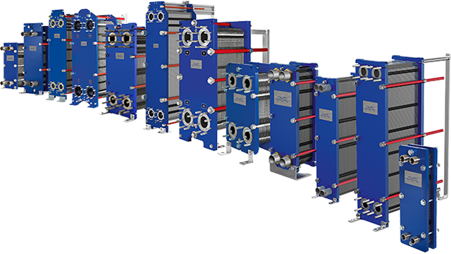
- Design Pressure M-Line
- >10 bar (145 psi)
- Marine Engine Room Modelle
- T6 (DN60, 800 kW) bis T35 (DN350, 35.000 kW)
- Marine FSRU Modelle
- TS45, T45, T50 (DN450-500, 45.000-55.000 kW)
- Temperaturbereich Standard
- 0–180°C (depending on model)
- FSRU Temperaturbereich
- -50 bis 150°C
- Plattentypen
- Chevron, Gemini Doppelwand, FlexFlow™
- M-Line (High Pressure Series: M3, M6, M10, M15)
- T-Series (Industrial: T2, T5, T6, T8, T10, T20, T25)
- AQ-Series (HVAC: AQ1, AQ2, AQ3, AQ4, AQ10)
- Marine Line (Engine Room: T6-T35; FSRU: TS45, T45, T50)
- Baseline (Competitive Line)
- Hygienic Line (Premium)
- Area: Gasket wear and embrittlementCheck: Inspect seals visually for cracks, hardening, swelling and discoloration; verify material compatibility with process fluids; check ClipGrip™ fastening. Aging symptoms and loss of elasticity are replacement indicators.
- Area: Clamping dimension and tightness (Tightening Dimension A)Check: Verify A-dimension per manufacturer specifications with caliper (metallic contact required). Keep bolts clean and lubricated. Avoid over-tightening. Perform regular re-tightening after operating hours. At too low A-dimension, pressure loss and leakage are to be expected.
- Area: Fouling and scale formation on plate surfacesCheck: Monitor pressure differential across heat exchanger (increase indicates deposits). Check heat duty versus design value. Optimize CIP intervals after performance audits. Deposits generate higher pump load (energy waste up to 8,000 kWh/year possible).
- Area: Plate corrosion and cracks / breakthroughsCheck: After disassembly, inspect plate surfaces for local measurements (pitting), cracks and perforation corrosion. Verify material compatibility with process fluid. Observe fatigue cracks especially at corners and transitions. When perforation occurs, plate is unrecoverable and must be replaced.
- Area: Pressure test and tightness inspectionCheck: After disassembly and cleaning, perform hydrostatic test per data sheet. Test pressure typically 1.5× operating pressure. Check external and internal leakage at all connections and plate edges. Document findings.
- Area: Plate sequence and alignment (5-point alignment)Check: After opening, verify plate sequence and honeycomb pattern (corrected chevron patterns must alternate). Activate/validate 5-point alignment system for larger units. Offset or misplacement leads to short-circuiting and reduced heat duty.
Type-universal inspection points for Alfa Laval Gasketed Plate Heat Exchangers (GPHE) (Alfa Laval, 2026-06). Per-model specs not auto-populated.
- Design Pressure M-Line
- >10 bar (145 psi)
- Marine Engine Room Modelle
- T6 (DN60, 800 kW) bis T35 (DN350, 35.000 kW)
- Marine FSRU Modelle
- TS45, T45, T50 (DN450-500, 45.000-55.000 kW)
- Temperaturbereich Standard
- 0–180°C (depending on model)
- FSRU Temperaturbereich
- -50 bis 150°C
- Plattentypen
- Chevron, Gemini Doppelwand, FlexFlow™
- M-Line (High Pressure Series: M3, M6, M10, M15)
- T-Series (Industrial: T2, T5, T6, T8, T10, T20, T25)
- AQ-Series (HVAC: AQ1, AQ2, AQ3, AQ4, AQ10)
- Marine Line (Engine Room: T6-T35; FSRU: TS45, T45, T50)
- Baseline (Competitive Line)
- Hygienic Line (Premium)
- Area: Gasket wear and embrittlementCheck: Inspect seals visually for cracks, hardening, swelling and discoloration; verify material compatibility with process fluids; check ClipGrip™ fastening. Aging symptoms and loss of elasticity are replacement indicators.
- Area: Clamping dimension and tightness (Tightening Dimension A)Check: Verify A-dimension per manufacturer specifications with caliper (metallic contact required). Keep bolts clean and lubricated. Avoid over-tightening. Perform regular re-tightening after operating hours. At too low A-dimension, pressure loss and leakage are to be expected.
- Area: Fouling and scale formation on plate surfacesCheck: Monitor pressure differential across heat exchanger (increase indicates deposits). Check heat duty versus design value. Optimize CIP intervals after performance audits. Deposits generate higher pump load (energy waste up to 8,000 kWh/year possible).
- Area: Plate corrosion and cracks / breakthroughsCheck: After disassembly, inspect plate surfaces for local measurements (pitting), cracks and perforation corrosion. Verify material compatibility with process fluid. Observe fatigue cracks especially at corners and transitions. When perforation occurs, plate is unrecoverable and must be replaced.
- Area: Pressure test and tightness inspectionCheck: After disassembly and cleaning, perform hydrostatic test per data sheet. Test pressure typically 1.5× operating pressure. Check external and internal leakage at all connections and plate edges. Document findings.
- Area: Plate sequence and alignment (5-point alignment)Check: After opening, verify plate sequence and honeycomb pattern (corrected chevron patterns must alternate). Activate/validate 5-point alignment system for larger units. Offset or misplacement leads to short-circuiting and reduced heat duty.
Type-universal inspection points for Alfa Laval Gasketed Plate Heat Exchangers (GPHE) (Alfa Laval, 2026-06). Per-model specs not auto-populated.
- Design Pressure M-Line
- >10 bar (145 psi)
- Marine Engine Room Modelle
- T6 (DN60, 800 kW) bis T35 (DN350, 35.000 kW)
- Marine FSRU Modelle
- TS45, T45, T50 (DN450-500, 45.000-55.000 kW)
- Temperaturbereich Standard
- 0–180°C (depending on model)
- FSRU Temperaturbereich
- -50 bis 150°C
- Plattentypen
- Chevron, Gemini Doppelwand, FlexFlow™
- M-Line (High Pressure Series: M3, M6, M10, M15)
- T-Series (Industrial: T2, T5, T6, T8, T10, T20, T25)
- AQ-Series (HVAC: AQ1, AQ2, AQ3, AQ4, AQ10)
- Marine Line (Engine Room: T6-T35; FSRU: TS45, T45, T50)
- Baseline (Competitive Line)
- Hygienic Line (Premium)
- Area: Gasket wear and embrittlementCheck: Inspect seals visually for cracks, hardening, swelling and discoloration; verify material compatibility with process fluids; check ClipGrip™ fastening. Aging symptoms and loss of elasticity are replacement indicators.
- Area: Clamping dimension and tightness (Tightening Dimension A)Check: Verify A-dimension per manufacturer specifications with caliper (metallic contact required). Keep bolts clean and lubricated. Avoid over-tightening. Perform regular re-tightening after operating hours. At too low A-dimension, pressure loss and leakage are to be expected.
- Area: Fouling and scale formation on plate surfacesCheck: Monitor pressure differential across heat exchanger (increase indicates deposits). Check heat duty versus design value. Optimize CIP intervals after performance audits. Deposits generate higher pump load (energy waste up to 8,000 kWh/year possible).
- Area: Plate corrosion and cracks / breakthroughsCheck: After disassembly, inspect plate surfaces for local measurements (pitting), cracks and perforation corrosion. Verify material compatibility with process fluid. Observe fatigue cracks especially at corners and transitions. When perforation occurs, plate is unrecoverable and must be replaced.
- Area: Pressure test and tightness inspectionCheck: After disassembly and cleaning, perform hydrostatic test per data sheet. Test pressure typically 1.5× operating pressure. Check external and internal leakage at all connections and plate edges. Document findings.
- Area: Plate sequence and alignment (5-point alignment)Check: After opening, verify plate sequence and honeycomb pattern (corrected chevron patterns must alternate). Activate/validate 5-point alignment system for larger units. Offset or misplacement leads to short-circuiting and reduced heat duty.
Type-universal inspection points for Alfa Laval Gasketed Plate Heat Exchangers (GPHE) (Alfa Laval, 2026-06). Per-model specs not auto-populated.
- Design Pressure M-Line
- >10 bar (145 psi)
- Marine Engine Room Modelle
- T6 (DN60, 800 kW) bis T35 (DN350, 35.000 kW)
- Marine FSRU Modelle
- TS45, T45, T50 (DN450-500, 45.000-55.000 kW)
- Temperaturbereich Standard
- 0–180°C (depending on model)
- FSRU Temperaturbereich
- -50 bis 150°C
- Plattentypen
- Chevron, Gemini Doppelwand, FlexFlow™
- M-Line (High Pressure Series: M3, M6, M10, M15)
- T-Series (Industrial: T2, T5, T6, T8, T10, T20, T25)
- AQ-Series (HVAC: AQ1, AQ2, AQ3, AQ4, AQ10)
- Marine Line (Engine Room: T6-T35; FSRU: TS45, T45, T50)
- Baseline (Competitive Line)
- Hygienic Line (Premium)
- Area: Gasket wear and embrittlementCheck: Inspect seals visually for cracks, hardening, swelling and discoloration; verify material compatibility with process fluids; check ClipGrip™ fastening. Aging symptoms and loss of elasticity are replacement indicators.
- Area: Clamping dimension and tightness (Tightening Dimension A)Check: Verify A-dimension per manufacturer specifications with caliper (metallic contact required). Keep bolts clean and lubricated. Avoid over-tightening. Perform regular re-tightening after operating hours. At too low A-dimension, pressure loss and leakage are to be expected.
- Area: Fouling and scale formation on plate surfacesCheck: Monitor pressure differential across heat exchanger (increase indicates deposits). Check heat duty versus design value. Optimize CIP intervals after performance audits. Deposits generate higher pump load (energy waste up to 8,000 kWh/year possible).
- Area: Plate corrosion and cracks / breakthroughsCheck: After disassembly, inspect plate surfaces for local measurements (pitting), cracks and perforation corrosion. Verify material compatibility with process fluid. Observe fatigue cracks especially at corners and transitions. When perforation occurs, plate is unrecoverable and must be replaced.
- Area: Pressure test and tightness inspectionCheck: After disassembly and cleaning, perform hydrostatic test per data sheet. Test pressure typically 1.5× operating pressure. Check external and internal leakage at all connections and plate edges. Document findings.
- Area: Plate sequence and alignment (5-point alignment)Check: After opening, verify plate sequence and honeycomb pattern (corrected chevron patterns must alternate). Activate/validate 5-point alignment system for larger units. Offset or misplacement leads to short-circuiting and reduced heat duty.
Type-universal inspection points for Alfa Laval Gasketed Plate Heat Exchangers (GPHE) (Alfa Laval, 2026-06). Per-model specs not auto-populated.
- Design Pressure M-Line
- >10 bar (145 psi)
- Marine Engine Room Modelle
- T6 (DN60, 800 kW) bis T35 (DN350, 35.000 kW)
- Marine FSRU Modelle
- TS45, T45, T50 (DN450-500, 45.000-55.000 kW)
- Temperaturbereich Standard
- 0–180°C (depending on model)
- FSRU Temperaturbereich
- -50 bis 150°C
- Plattentypen
- Chevron, Gemini Doppelwand, FlexFlow™
- M-Line (High Pressure Series: M3, M6, M10, M15)
- T-Series (Industrial: T2, T5, T6, T8, T10, T20, T25)
- AQ-Series (HVAC: AQ1, AQ2, AQ3, AQ4, AQ10)
- Marine Line (Engine Room: T6-T35; FSRU: TS45, T45, T50)
- Baseline (Competitive Line)
- Hygienic Line (Premium)
- Area: Gasket wear and embrittlementCheck: Inspect seals visually for cracks, hardening, swelling and discoloration; verify material compatibility with process fluids; check ClipGrip™ fastening. Aging symptoms and loss of elasticity are replacement indicators.
- Area: Clamping dimension and tightness (Tightening Dimension A)Check: Verify A-dimension per manufacturer specifications with caliper (metallic contact required). Keep bolts clean and lubricated. Avoid over-tightening. Perform regular re-tightening after operating hours. At too low A-dimension, pressure loss and leakage are to be expected.
- Area: Fouling and scale formation on plate surfacesCheck: Monitor pressure differential across heat exchanger (increase indicates deposits). Check heat duty versus design value. Optimize CIP intervals after performance audits. Deposits generate higher pump load (energy waste up to 8,000 kWh/year possible).
- Area: Plate corrosion and cracks / breakthroughsCheck: After disassembly, inspect plate surfaces for local measurements (pitting), cracks and perforation corrosion. Verify material compatibility with process fluid. Observe fatigue cracks especially at corners and transitions. When perforation occurs, plate is unrecoverable and must be replaced.
- Area: Pressure test and tightness inspectionCheck: After disassembly and cleaning, perform hydrostatic test per data sheet. Test pressure typically 1.5× operating pressure. Check external and internal leakage at all connections and plate edges. Document findings.
- Area: Plate sequence and alignment (5-point alignment)Check: After opening, verify plate sequence and honeycomb pattern (corrected chevron patterns must alternate). Activate/validate 5-point alignment system for larger units. Offset or misplacement leads to short-circuiting and reduced heat duty.
Type-universal inspection points for Alfa Laval Gasketed Plate Heat Exchangers (GPHE) (Alfa Laval, 2026-06). Per-model specs not auto-populated.

- Design Pressure M-Line
- >10 bar (145 psi)
- Marine Engine Room Modelle
- T6 (DN60, 800 kW) bis T35 (DN350, 35.000 kW)
- Marine FSRU Modelle
- TS45, T45, T50 (DN450-500, 45.000-55.000 kW)
- Temperaturbereich Standard
- 0–180°C (depending on model)
- FSRU Temperaturbereich
- -50 bis 150°C
- Plattentypen
- Chevron, Gemini Doppelwand, FlexFlow™
- M-Line (High Pressure Series: M3, M6, M10, M15)
- T-Series (Industrial: T2, T5, T6, T8, T10, T20, T25)
- AQ-Series (HVAC: AQ1, AQ2, AQ3, AQ4, AQ10)
- Marine Line (Engine Room: T6-T35; FSRU: TS45, T45, T50)
- Baseline (Competitive Line)
- Hygienic Line (Premium)
- Area: Gasket wear and embrittlementCheck: Inspect seals visually for cracks, hardening, swelling and discoloration; verify material compatibility with process fluids; check ClipGrip™ fastening. Aging symptoms and loss of elasticity are replacement indicators.
- Area: Clamping dimension and tightness (Tightening Dimension A)Check: Verify A-dimension per manufacturer specifications with caliper (metallic contact required). Keep bolts clean and lubricated. Avoid over-tightening. Perform regular re-tightening after operating hours. At too low A-dimension, pressure loss and leakage are to be expected.
- Area: Fouling and scale formation on plate surfacesCheck: Monitor pressure differential across heat exchanger (increase indicates deposits). Check heat duty versus design value. Optimize CIP intervals after performance audits. Deposits generate higher pump load (energy waste up to 8,000 kWh/year possible).
- Area: Plate corrosion and cracks / breakthroughsCheck: After disassembly, inspect plate surfaces for local measurements (pitting), cracks and perforation corrosion. Verify material compatibility with process fluid. Observe fatigue cracks especially at corners and transitions. When perforation occurs, plate is unrecoverable and must be replaced.
- Area: Pressure test and tightness inspectionCheck: After disassembly and cleaning, perform hydrostatic test per data sheet. Test pressure typically 1.5× operating pressure. Check external and internal leakage at all connections and plate edges. Document findings.
- Area: Plate sequence and alignment (5-point alignment)Check: After opening, verify plate sequence and honeycomb pattern (corrected chevron patterns must alternate). Activate/validate 5-point alignment system for larger units. Offset or misplacement leads to short-circuiting and reduced heat duty.
Type-universal inspection points for Alfa Laval Gasketed Plate Heat Exchangers (GPHE) (Alfa Laval, 2026-06). Per-model specs not auto-populated.
- Design Pressure M-Line
- >10 bar (145 psi)
- Marine Engine Room Modelle
- T6 (DN60, 800 kW) bis T35 (DN350, 35.000 kW)
- Marine FSRU Modelle
- TS45, T45, T50 (DN450-500, 45.000-55.000 kW)
- Temperaturbereich Standard
- 0–180°C (depending on model)
- FSRU Temperaturbereich
- -50 bis 150°C
- Plattentypen
- Chevron, Gemini Doppelwand, FlexFlow™
- M-Line (High Pressure Series: M3, M6, M10, M15)
- T-Series (Industrial: T2, T5, T6, T8, T10, T20, T25)
- AQ-Series (HVAC: AQ1, AQ2, AQ3, AQ4, AQ10)
- Marine Line (Engine Room: T6-T35; FSRU: TS45, T45, T50)
- Baseline (Competitive Line)
- Hygienic Line (Premium)
- Area: Gasket wear and embrittlementCheck: Inspect seals visually for cracks, hardening, swelling and discoloration; verify material compatibility with process fluids; check ClipGrip™ fastening. Aging symptoms and loss of elasticity are replacement indicators.
- Area: Clamping dimension and tightness (Tightening Dimension A)Check: Verify A-dimension per manufacturer specifications with caliper (metallic contact required). Keep bolts clean and lubricated. Avoid over-tightening. Perform regular re-tightening after operating hours. At too low A-dimension, pressure loss and leakage are to be expected.
- Area: Fouling and scale formation on plate surfacesCheck: Monitor pressure differential across heat exchanger (increase indicates deposits). Check heat duty versus design value. Optimize CIP intervals after performance audits. Deposits generate higher pump load (energy waste up to 8,000 kWh/year possible).
- Area: Plate corrosion and cracks / breakthroughsCheck: After disassembly, inspect plate surfaces for local measurements (pitting), cracks and perforation corrosion. Verify material compatibility with process fluid. Observe fatigue cracks especially at corners and transitions. When perforation occurs, plate is unrecoverable and must be replaced.
- Area: Pressure test and tightness inspectionCheck: After disassembly and cleaning, perform hydrostatic test per data sheet. Test pressure typically 1.5× operating pressure. Check external and internal leakage at all connections and plate edges. Document findings.
- Area: Plate sequence and alignment (5-point alignment)Check: After opening, verify plate sequence and honeycomb pattern (corrected chevron patterns must alternate). Activate/validate 5-point alignment system for larger units. Offset or misplacement leads to short-circuiting and reduced heat duty.
Type-universal inspection points for Alfa Laval Gasketed Plate Heat Exchangers (GPHE) (Alfa Laval, 2026-06). Per-model specs not auto-populated.
- Design Pressure M-Line
- >10 bar (145 psi)
- Marine Engine Room Modelle
- T6 (DN60, 800 kW) bis T35 (DN350, 35.000 kW)
- Marine FSRU Modelle
- TS45, T45, T50 (DN450-500, 45.000-55.000 kW)
- Temperaturbereich Standard
- 0–180°C (depending on model)
- FSRU Temperaturbereich
- -50 bis 150°C
- Plattentypen
- Chevron, Gemini Doppelwand, FlexFlow™
- M-Line (High Pressure Series: M3, M6, M10, M15)
- T-Series (Industrial: T2, T5, T6, T8, T10, T20, T25)
- AQ-Series (HVAC: AQ1, AQ2, AQ3, AQ4, AQ10)
- Marine Line (Engine Room: T6-T35; FSRU: TS45, T45, T50)
- Baseline (Competitive Line)
- Hygienic Line (Premium)
- Area: Gasket wear and embrittlementCheck: Inspect seals visually for cracks, hardening, swelling and discoloration; verify material compatibility with process fluids; check ClipGrip™ fastening. Aging symptoms and loss of elasticity are replacement indicators.
- Area: Clamping dimension and tightness (Tightening Dimension A)Check: Verify A-dimension per manufacturer specifications with caliper (metallic contact required). Keep bolts clean and lubricated. Avoid over-tightening. Perform regular re-tightening after operating hours. At too low A-dimension, pressure loss and leakage are to be expected.
- Area: Fouling and scale formation on plate surfacesCheck: Monitor pressure differential across heat exchanger (increase indicates deposits). Check heat duty versus design value. Optimize CIP intervals after performance audits. Deposits generate higher pump load (energy waste up to 8,000 kWh/year possible).
- Area: Plate corrosion and cracks / breakthroughsCheck: After disassembly, inspect plate surfaces for local measurements (pitting), cracks and perforation corrosion. Verify material compatibility with process fluid. Observe fatigue cracks especially at corners and transitions. When perforation occurs, plate is unrecoverable and must be replaced.
- Area: Pressure test and tightness inspectionCheck: After disassembly and cleaning, perform hydrostatic test per data sheet. Test pressure typically 1.5× operating pressure. Check external and internal leakage at all connections and plate edges. Document findings.
- Area: Plate sequence and alignment (5-point alignment)Check: After opening, verify plate sequence and honeycomb pattern (corrected chevron patterns must alternate). Activate/validate 5-point alignment system for larger units. Offset or misplacement leads to short-circuiting and reduced heat duty.
Type-universal inspection points for Alfa Laval Gasketed Plate Heat Exchangers (GPHE) (Alfa Laval, 2026-06). Per-model specs not auto-populated.
- Design Pressure M-Line
- >10 bar (145 psi)
- Marine Engine Room Modelle
- T6 (DN60, 800 kW) bis T35 (DN350, 35.000 kW)
- Marine FSRU Modelle
- TS45, T45, T50 (DN450-500, 45.000-55.000 kW)
- Temperaturbereich Standard
- 0–180°C (depending on model)
- FSRU Temperaturbereich
- -50 bis 150°C
- Plattentypen
- Chevron, Gemini Doppelwand, FlexFlow™
- M-Line (High Pressure Series: M3, M6, M10, M15)
- T-Series (Industrial: T2, T5, T6, T8, T10, T20, T25)
- AQ-Series (HVAC: AQ1, AQ2, AQ3, AQ4, AQ10)
- Marine Line (Engine Room: T6-T35; FSRU: TS45, T45, T50)
- Baseline (Competitive Line)
- Hygienic Line (Premium)
- Area: Gasket wear and embrittlementCheck: Inspect seals visually for cracks, hardening, swelling and discoloration; verify material compatibility with process fluids; check ClipGrip™ fastening. Aging symptoms and loss of elasticity are replacement indicators.
- Area: Clamping dimension and tightness (Tightening Dimension A)Check: Verify A-dimension per manufacturer specifications with caliper (metallic contact required). Keep bolts clean and lubricated. Avoid over-tightening. Perform regular re-tightening after operating hours. At too low A-dimension, pressure loss and leakage are to be expected.
- Area: Fouling and scale formation on plate surfacesCheck: Monitor pressure differential across heat exchanger (increase indicates deposits). Check heat duty versus design value. Optimize CIP intervals after performance audits. Deposits generate higher pump load (energy waste up to 8,000 kWh/year possible).
- Area: Plate corrosion and cracks / breakthroughsCheck: After disassembly, inspect plate surfaces for local measurements (pitting), cracks and perforation corrosion. Verify material compatibility with process fluid. Observe fatigue cracks especially at corners and transitions. When perforation occurs, plate is unrecoverable and must be replaced.
- Area: Pressure test and tightness inspectionCheck: After disassembly and cleaning, perform hydrostatic test per data sheet. Test pressure typically 1.5× operating pressure. Check external and internal leakage at all connections and plate edges. Document findings.
- Area: Plate sequence and alignment (5-point alignment)Check: After opening, verify plate sequence and honeycomb pattern (corrected chevron patterns must alternate). Activate/validate 5-point alignment system for larger units. Offset or misplacement leads to short-circuiting and reduced heat duty.
Type-universal inspection points for Alfa Laval Gasketed Plate Heat Exchangers (GPHE) (Alfa Laval, 2026-06). Per-model specs not auto-populated.
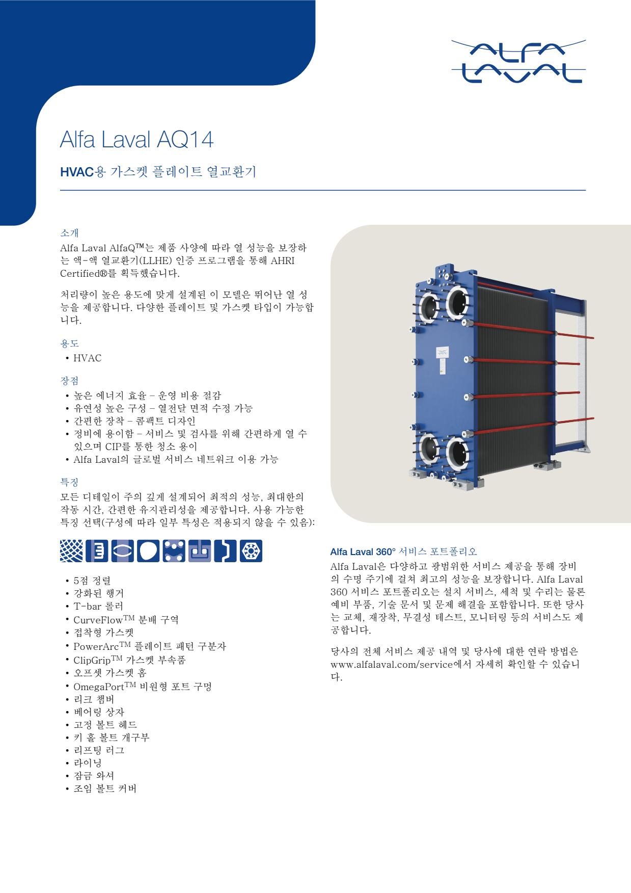
- Design Pressure M-Line
- >10 bar (145 psi)
- Marine Engine Room Modelle
- T6 (DN60, 800 kW) bis T35 (DN350, 35.000 kW)
- Marine FSRU Modelle
- TS45, T45, T50 (DN450-500, 45.000-55.000 kW)
- Temperaturbereich Standard
- 0–180°C (depending on model)
- FSRU Temperaturbereich
- -50 bis 150°C
- Plattentypen
- Chevron, Gemini Doppelwand, FlexFlow™
- M-Line (High Pressure Series: M3, M6, M10, M15)
- T-Series (Industrial: T2, T5, T6, T8, T10, T20, T25)
- AQ-Series (HVAC: AQ1, AQ2, AQ3, AQ4, AQ10)
- Marine Line (Engine Room: T6-T35; FSRU: TS45, T45, T50)
- Baseline (Competitive Line)
- Hygienic Line (Premium)
- Area: Gasket wear and embrittlementCheck: Inspect seals visually for cracks, hardening, swelling and discoloration; verify material compatibility with process fluids; check ClipGrip™ fastening. Aging symptoms and loss of elasticity are replacement indicators.
- Area: Clamping dimension and tightness (Tightening Dimension A)Check: Verify A-dimension per manufacturer specifications with caliper (metallic contact required). Keep bolts clean and lubricated. Avoid over-tightening. Perform regular re-tightening after operating hours. At too low A-dimension, pressure loss and leakage are to be expected.
- Area: Fouling and scale formation on plate surfacesCheck: Monitor pressure differential across heat exchanger (increase indicates deposits). Check heat duty versus design value. Optimize CIP intervals after performance audits. Deposits generate higher pump load (energy waste up to 8,000 kWh/year possible).
- Area: Plate corrosion and cracks / breakthroughsCheck: After disassembly, inspect plate surfaces for local measurements (pitting), cracks and perforation corrosion. Verify material compatibility with process fluid. Observe fatigue cracks especially at corners and transitions. When perforation occurs, plate is unrecoverable and must be replaced.
- Area: Pressure test and tightness inspectionCheck: After disassembly and cleaning, perform hydrostatic test per data sheet. Test pressure typically 1.5× operating pressure. Check external and internal leakage at all connections and plate edges. Document findings.
- Area: Plate sequence and alignment (5-point alignment)Check: After opening, verify plate sequence and honeycomb pattern (corrected chevron patterns must alternate). Activate/validate 5-point alignment system for larger units. Offset or misplacement leads to short-circuiting and reduced heat duty.
Type-universal inspection points for Alfa Laval Gasketed Plate Heat Exchangers (GPHE) (Alfa Laval, 2026-06). Per-model specs not auto-populated.
- Design Pressure M-Line
- >10 bar (145 psi)
- Marine Engine Room Modelle
- T6 (DN60, 800 kW) bis T35 (DN350, 35.000 kW)
- Marine FSRU Modelle
- TS45, T45, T50 (DN450-500, 45.000-55.000 kW)
- Temperaturbereich Standard
- 0–180°C (depending on model)
- FSRU Temperaturbereich
- -50 bis 150°C
- Plattentypen
- Chevron, Gemini Doppelwand, FlexFlow™
- M-Line (High Pressure Series: M3, M6, M10, M15)
- T-Series (Industrial: T2, T5, T6, T8, T10, T20, T25)
- AQ-Series (HVAC: AQ1, AQ2, AQ3, AQ4, AQ10)
- Marine Line (Engine Room: T6-T35; FSRU: TS45, T45, T50)
- Baseline (Competitive Line)
- Hygienic Line (Premium)
- Area: Gasket wear and embrittlementCheck: Inspect seals visually for cracks, hardening, swelling and discoloration; verify material compatibility with process fluids; check ClipGrip™ fastening. Aging symptoms and loss of elasticity are replacement indicators.
- Area: Clamping dimension and tightness (Tightening Dimension A)Check: Verify A-dimension per manufacturer specifications with caliper (metallic contact required). Keep bolts clean and lubricated. Avoid over-tightening. Perform regular re-tightening after operating hours. At too low A-dimension, pressure loss and leakage are to be expected.
- Area: Fouling and scale formation on plate surfacesCheck: Monitor pressure differential across heat exchanger (increase indicates deposits). Check heat duty versus design value. Optimize CIP intervals after performance audits. Deposits generate higher pump load (energy waste up to 8,000 kWh/year possible).
- Area: Plate corrosion and cracks / breakthroughsCheck: After disassembly, inspect plate surfaces for local measurements (pitting), cracks and perforation corrosion. Verify material compatibility with process fluid. Observe fatigue cracks especially at corners and transitions. When perforation occurs, plate is unrecoverable and must be replaced.
- Area: Pressure test and tightness inspectionCheck: After disassembly and cleaning, perform hydrostatic test per data sheet. Test pressure typically 1.5× operating pressure. Check external and internal leakage at all connections and plate edges. Document findings.
- Area: Plate sequence and alignment (5-point alignment)Check: After opening, verify plate sequence and honeycomb pattern (corrected chevron patterns must alternate). Activate/validate 5-point alignment system for larger units. Offset or misplacement leads to short-circuiting and reduced heat duty.
Type-universal inspection points for Alfa Laval Gasketed Plate Heat Exchangers (GPHE) (Alfa Laval, 2026-06). Per-model specs not auto-populated.
- Design Pressure M-Line
- >10 bar (145 psi)
- Marine Engine Room Modelle
- T6 (DN60, 800 kW) bis T35 (DN350, 35.000 kW)
- Marine FSRU Modelle
- TS45, T45, T50 (DN450-500, 45.000-55.000 kW)
- Temperaturbereich Standard
- 0–180°C (depending on model)
- FSRU Temperaturbereich
- -50 bis 150°C
- Plattentypen
- Chevron, Gemini Doppelwand, FlexFlow™
- M-Line (High Pressure Series: M3, M6, M10, M15)
- T-Series (Industrial: T2, T5, T6, T8, T10, T20, T25)
- AQ-Series (HVAC: AQ1, AQ2, AQ3, AQ4, AQ10)
- Marine Line (Engine Room: T6-T35; FSRU: TS45, T45, T50)
- Baseline (Competitive Line)
- Hygienic Line (Premium)
- Area: Gasket wear and embrittlementCheck: Inspect seals visually for cracks, hardening, swelling and discoloration; verify material compatibility with process fluids; check ClipGrip™ fastening. Aging symptoms and loss of elasticity are replacement indicators.
- Area: Clamping dimension and tightness (Tightening Dimension A)Check: Verify A-dimension per manufacturer specifications with caliper (metallic contact required). Keep bolts clean and lubricated. Avoid over-tightening. Perform regular re-tightening after operating hours. At too low A-dimension, pressure loss and leakage are to be expected.
- Area: Fouling and scale formation on plate surfacesCheck: Monitor pressure differential across heat exchanger (increase indicates deposits). Check heat duty versus design value. Optimize CIP intervals after performance audits. Deposits generate higher pump load (energy waste up to 8,000 kWh/year possible).
- Area: Plate corrosion and cracks / breakthroughsCheck: After disassembly, inspect plate surfaces for local measurements (pitting), cracks and perforation corrosion. Verify material compatibility with process fluid. Observe fatigue cracks especially at corners and transitions. When perforation occurs, plate is unrecoverable and must be replaced.
- Area: Pressure test and tightness inspectionCheck: After disassembly and cleaning, perform hydrostatic test per data sheet. Test pressure typically 1.5× operating pressure. Check external and internal leakage at all connections and plate edges. Document findings.
- Area: Plate sequence and alignment (5-point alignment)Check: After opening, verify plate sequence and honeycomb pattern (corrected chevron patterns must alternate). Activate/validate 5-point alignment system for larger units. Offset or misplacement leads to short-circuiting and reduced heat duty.
Type-universal inspection points for Alfa Laval Gasketed Plate Heat Exchangers (GPHE) (Alfa Laval, 2026-06). Per-model specs not auto-populated.
- Design Pressure M-Line
- >10 bar (145 psi)
- Marine Engine Room Modelle
- T6 (DN60, 800 kW) bis T35 (DN350, 35.000 kW)
- Marine FSRU Modelle
- TS45, T45, T50 (DN450-500, 45.000-55.000 kW)
- Temperaturbereich Standard
- 0–180°C (depending on model)
- FSRU Temperaturbereich
- -50 bis 150°C
- Plattentypen
- Chevron, Gemini Doppelwand, FlexFlow™
- M-Line (High Pressure Series: M3, M6, M10, M15)
- T-Series (Industrial: T2, T5, T6, T8, T10, T20, T25)
- AQ-Series (HVAC: AQ1, AQ2, AQ3, AQ4, AQ10)
- Marine Line (Engine Room: T6-T35; FSRU: TS45, T45, T50)
- Baseline (Competitive Line)
- Hygienic Line (Premium)
- Area: Gasket wear and embrittlementCheck: Inspect seals visually for cracks, hardening, swelling and discoloration; verify material compatibility with process fluids; check ClipGrip™ fastening. Aging symptoms and loss of elasticity are replacement indicators.
- Area: Clamping dimension and tightness (Tightening Dimension A)Check: Verify A-dimension per manufacturer specifications with caliper (metallic contact required). Keep bolts clean and lubricated. Avoid over-tightening. Perform regular re-tightening after operating hours. At too low A-dimension, pressure loss and leakage are to be expected.
- Area: Fouling and scale formation on plate surfacesCheck: Monitor pressure differential across heat exchanger (increase indicates deposits). Check heat duty versus design value. Optimize CIP intervals after performance audits. Deposits generate higher pump load (energy waste up to 8,000 kWh/year possible).
- Area: Plate corrosion and cracks / breakthroughsCheck: After disassembly, inspect plate surfaces for local measurements (pitting), cracks and perforation corrosion. Verify material compatibility with process fluid. Observe fatigue cracks especially at corners and transitions. When perforation occurs, plate is unrecoverable and must be replaced.
- Area: Pressure test and tightness inspectionCheck: After disassembly and cleaning, perform hydrostatic test per data sheet. Test pressure typically 1.5× operating pressure. Check external and internal leakage at all connections and plate edges. Document findings.
- Area: Plate sequence and alignment (5-point alignment)Check: After opening, verify plate sequence and honeycomb pattern (corrected chevron patterns must alternate). Activate/validate 5-point alignment system for larger units. Offset or misplacement leads to short-circuiting and reduced heat duty.
Type-universal inspection points for Alfa Laval Gasketed Plate Heat Exchangers (GPHE) (Alfa Laval, 2026-06). Per-model specs not auto-populated.
- Design Pressure M-Line
- >10 bar (145 psi)
- Marine Engine Room Modelle
- T6 (DN60, 800 kW) bis T35 (DN350, 35.000 kW)
- Marine FSRU Modelle
- TS45, T45, T50 (DN450-500, 45.000-55.000 kW)
- Temperaturbereich Standard
- 0–180°C (depending on model)
- FSRU Temperaturbereich
- -50 bis 150°C
- Plattentypen
- Chevron, Gemini Doppelwand, FlexFlow™
- M-Line (High Pressure Series: M3, M6, M10, M15)
- T-Series (Industrial: T2, T5, T6, T8, T10, T20, T25)
- AQ-Series (HVAC: AQ1, AQ2, AQ3, AQ4, AQ10)
- Marine Line (Engine Room: T6-T35; FSRU: TS45, T45, T50)
- Baseline (Competitive Line)
- Hygienic Line (Premium)
- Area: Gasket wear and embrittlementCheck: Inspect seals visually for cracks, hardening, swelling and discoloration; verify material compatibility with process fluids; check ClipGrip™ fastening. Aging symptoms and loss of elasticity are replacement indicators.
- Area: Clamping dimension and tightness (Tightening Dimension A)Check: Verify A-dimension per manufacturer specifications with caliper (metallic contact required). Keep bolts clean and lubricated. Avoid over-tightening. Perform regular re-tightening after operating hours. At too low A-dimension, pressure loss and leakage are to be expected.
- Area: Fouling and scale formation on plate surfacesCheck: Monitor pressure differential across heat exchanger (increase indicates deposits). Check heat duty versus design value. Optimize CIP intervals after performance audits. Deposits generate higher pump load (energy waste up to 8,000 kWh/year possible).
- Area: Plate corrosion and cracks / breakthroughsCheck: After disassembly, inspect plate surfaces for local measurements (pitting), cracks and perforation corrosion. Verify material compatibility with process fluid. Observe fatigue cracks especially at corners and transitions. When perforation occurs, plate is unrecoverable and must be replaced.
- Area: Pressure test and tightness inspectionCheck: After disassembly and cleaning, perform hydrostatic test per data sheet. Test pressure typically 1.5× operating pressure. Check external and internal leakage at all connections and plate edges. Document findings.
- Area: Plate sequence and alignment (5-point alignment)Check: After opening, verify plate sequence and honeycomb pattern (corrected chevron patterns must alternate). Activate/validate 5-point alignment system for larger units. Offset or misplacement leads to short-circuiting and reduced heat duty.
Type-universal inspection points for Alfa Laval Gasketed Plate Heat Exchangers (GPHE) (Alfa Laval, 2026-06). Per-model specs not auto-populated.
- Design Pressure M-Line
- >10 bar (145 psi)
- Marine Engine Room Modelle
- T6 (DN60, 800 kW) bis T35 (DN350, 35.000 kW)
- Marine FSRU Modelle
- TS45, T45, T50 (DN450-500, 45.000-55.000 kW)
- Temperaturbereich Standard
- 0–180°C (depending on model)
- FSRU Temperaturbereich
- -50 bis 150°C
- Plattentypen
- Chevron, Gemini Doppelwand, FlexFlow™
- M-Line (High Pressure Series: M3, M6, M10, M15)
- T-Series (Industrial: T2, T5, T6, T8, T10, T20, T25)
- AQ-Series (HVAC: AQ1, AQ2, AQ3, AQ4, AQ10)
- Marine Line (Engine Room: T6-T35; FSRU: TS45, T45, T50)
- Baseline (Competitive Line)
- Hygienic Line (Premium)
- Area: Gasket wear and embrittlementCheck: Inspect seals visually for cracks, hardening, swelling and discoloration; verify material compatibility with process fluids; check ClipGrip™ fastening. Aging symptoms and loss of elasticity are replacement indicators.
- Area: Clamping dimension and tightness (Tightening Dimension A)Check: Verify A-dimension per manufacturer specifications with caliper (metallic contact required). Keep bolts clean and lubricated. Avoid over-tightening. Perform regular re-tightening after operating hours. At too low A-dimension, pressure loss and leakage are to be expected.
- Area: Fouling and scale formation on plate surfacesCheck: Monitor pressure differential across heat exchanger (increase indicates deposits). Check heat duty versus design value. Optimize CIP intervals after performance audits. Deposits generate higher pump load (energy waste up to 8,000 kWh/year possible).
- Area: Plate corrosion and cracks / breakthroughsCheck: After disassembly, inspect plate surfaces for local measurements (pitting), cracks and perforation corrosion. Verify material compatibility with process fluid. Observe fatigue cracks especially at corners and transitions. When perforation occurs, plate is unrecoverable and must be replaced.
- Area: Pressure test and tightness inspectionCheck: After disassembly and cleaning, perform hydrostatic test per data sheet. Test pressure typically 1.5× operating pressure. Check external and internal leakage at all connections and plate edges. Document findings.
- Area: Plate sequence and alignment (5-point alignment)Check: After opening, verify plate sequence and honeycomb pattern (corrected chevron patterns must alternate). Activate/validate 5-point alignment system for larger units. Offset or misplacement leads to short-circuiting and reduced heat duty.
Type-universal inspection points for Alfa Laval Gasketed Plate Heat Exchangers (GPHE) (Alfa Laval, 2026-06). Per-model specs not auto-populated.
- Design Pressure M-Line
- >10 bar (145 psi)
- Marine Engine Room Modelle
- T6 (DN60, 800 kW) bis T35 (DN350, 35.000 kW)
- Marine FSRU Modelle
- TS45, T45, T50 (DN450-500, 45.000-55.000 kW)
- Temperaturbereich Standard
- 0–180°C (depending on model)
- FSRU Temperaturbereich
- -50 bis 150°C
- Plattentypen
- Chevron, Gemini Doppelwand, FlexFlow™
- M-Line (High Pressure Series: M3, M6, M10, M15)
- T-Series (Industrial: T2, T5, T6, T8, T10, T20, T25)
- AQ-Series (HVAC: AQ1, AQ2, AQ3, AQ4, AQ10)
- Marine Line (Engine Room: T6-T35; FSRU: TS45, T45, T50)
- Baseline (Competitive Line)
- Hygienic Line (Premium)
- Area: Gasket wear and embrittlementCheck: Inspect seals visually for cracks, hardening, swelling and discoloration; verify material compatibility with process fluids; check ClipGrip™ fastening. Aging symptoms and loss of elasticity are replacement indicators.
- Area: Clamping dimension and tightness (Tightening Dimension A)Check: Verify A-dimension per manufacturer specifications with caliper (metallic contact required). Keep bolts clean and lubricated. Avoid over-tightening. Perform regular re-tightening after operating hours. At too low A-dimension, pressure loss and leakage are to be expected.
- Area: Fouling and scale formation on plate surfacesCheck: Monitor pressure differential across heat exchanger (increase indicates deposits). Check heat duty versus design value. Optimize CIP intervals after performance audits. Deposits generate higher pump load (energy waste up to 8,000 kWh/year possible).
- Area: Plate corrosion and cracks / breakthroughsCheck: After disassembly, inspect plate surfaces for local measurements (pitting), cracks and perforation corrosion. Verify material compatibility with process fluid. Observe fatigue cracks especially at corners and transitions. When perforation occurs, plate is unrecoverable and must be replaced.
- Area: Pressure test and tightness inspectionCheck: After disassembly and cleaning, perform hydrostatic test per data sheet. Test pressure typically 1.5× operating pressure. Check external and internal leakage at all connections and plate edges. Document findings.
- Area: Plate sequence and alignment (5-point alignment)Check: After opening, verify plate sequence and honeycomb pattern (corrected chevron patterns must alternate). Activate/validate 5-point alignment system for larger units. Offset or misplacement leads to short-circuiting and reduced heat duty.
Type-universal inspection points for Alfa Laval Gasketed Plate Heat Exchangers (GPHE) (Alfa Laval, 2026-06). Per-model specs not auto-populated.
- Design Pressure M-Line
- >10 bar (145 psi)
- Marine Engine Room Modelle
- T6 (DN60, 800 kW) bis T35 (DN350, 35.000 kW)
- Marine FSRU Modelle
- TS45, T45, T50 (DN450-500, 45.000-55.000 kW)
- Temperaturbereich Standard
- 0–180°C (depending on model)
- FSRU Temperaturbereich
- -50 bis 150°C
- Plattentypen
- Chevron, Gemini Doppelwand, FlexFlow™
- M-Line (High Pressure Series: M3, M6, M10, M15)
- T-Series (Industrial: T2, T5, T6, T8, T10, T20, T25)
- AQ-Series (HVAC: AQ1, AQ2, AQ3, AQ4, AQ10)
- Marine Line (Engine Room: T6-T35; FSRU: TS45, T45, T50)
- Baseline (Competitive Line)
- Hygienic Line (Premium)
- Area: Gasket wear and embrittlementCheck: Inspect seals visually for cracks, hardening, swelling and discoloration; verify material compatibility with process fluids; check ClipGrip™ fastening. Aging symptoms and loss of elasticity are replacement indicators.
- Area: Clamping dimension and tightness (Tightening Dimension A)Check: Verify A-dimension per manufacturer specifications with caliper (metallic contact required). Keep bolts clean and lubricated. Avoid over-tightening. Perform regular re-tightening after operating hours. At too low A-dimension, pressure loss and leakage are to be expected.
- Area: Fouling and scale formation on plate surfacesCheck: Monitor pressure differential across heat exchanger (increase indicates deposits). Check heat duty versus design value. Optimize CIP intervals after performance audits. Deposits generate higher pump load (energy waste up to 8,000 kWh/year possible).
- Area: Plate corrosion and cracks / breakthroughsCheck: After disassembly, inspect plate surfaces for local measurements (pitting), cracks and perforation corrosion. Verify material compatibility with process fluid. Observe fatigue cracks especially at corners and transitions. When perforation occurs, plate is unrecoverable and must be replaced.
- Area: Pressure test and tightness inspectionCheck: After disassembly and cleaning, perform hydrostatic test per data sheet. Test pressure typically 1.5× operating pressure. Check external and internal leakage at all connections and plate edges. Document findings.
- Area: Plate sequence and alignment (5-point alignment)Check: After opening, verify plate sequence and honeycomb pattern (corrected chevron patterns must alternate). Activate/validate 5-point alignment system for larger units. Offset or misplacement leads to short-circuiting and reduced heat duty.
Type-universal inspection points for Alfa Laval Gasketed Plate Heat Exchangers (GPHE) (Alfa Laval, 2026-06). Per-model specs not auto-populated.
- Design Pressure M-Line
- >10 bar (145 psi)
- Marine Engine Room Modelle
- T6 (DN60, 800 kW) bis T35 (DN350, 35.000 kW)
- Marine FSRU Modelle
- TS45, T45, T50 (DN450-500, 45.000-55.000 kW)
- Temperaturbereich Standard
- 0–180°C (depending on model)
- FSRU Temperaturbereich
- -50 bis 150°C
- Plattentypen
- Chevron, Gemini Doppelwand, FlexFlow™
- M-Line (High Pressure Series: M3, M6, M10, M15)
- T-Series (Industrial: T2, T5, T6, T8, T10, T20, T25)
- AQ-Series (HVAC: AQ1, AQ2, AQ3, AQ4, AQ10)
- Marine Line (Engine Room: T6-T35; FSRU: TS45, T45, T50)
- Baseline (Competitive Line)
- Hygienic Line (Premium)
- Area: Gasket wear and embrittlementCheck: Inspect seals visually for cracks, hardening, swelling and discoloration; verify material compatibility with process fluids; check ClipGrip™ fastening. Aging symptoms and loss of elasticity are replacement indicators.
- Area: Clamping dimension and tightness (Tightening Dimension A)Check: Verify A-dimension per manufacturer specifications with caliper (metallic contact required). Keep bolts clean and lubricated. Avoid over-tightening. Perform regular re-tightening after operating hours. At too low A-dimension, pressure loss and leakage are to be expected.
- Area: Fouling and scale formation on plate surfacesCheck: Monitor pressure differential across heat exchanger (increase indicates deposits). Check heat duty versus design value. Optimize CIP intervals after performance audits. Deposits generate higher pump load (energy waste up to 8,000 kWh/year possible).
- Area: Plate corrosion and cracks / breakthroughsCheck: After disassembly, inspect plate surfaces for local measurements (pitting), cracks and perforation corrosion. Verify material compatibility with process fluid. Observe fatigue cracks especially at corners and transitions. When perforation occurs, plate is unrecoverable and must be replaced.
- Area: Pressure test and tightness inspectionCheck: After disassembly and cleaning, perform hydrostatic test per data sheet. Test pressure typically 1.5× operating pressure. Check external and internal leakage at all connections and plate edges. Document findings.
- Area: Plate sequence and alignment (5-point alignment)Check: After opening, verify plate sequence and honeycomb pattern (corrected chevron patterns must alternate). Activate/validate 5-point alignment system for larger units. Offset or misplacement leads to short-circuiting and reduced heat duty.
Type-universal inspection points for Alfa Laval Gasketed Plate Heat Exchangers (GPHE) (Alfa Laval, 2026-06). Per-model specs not auto-populated.
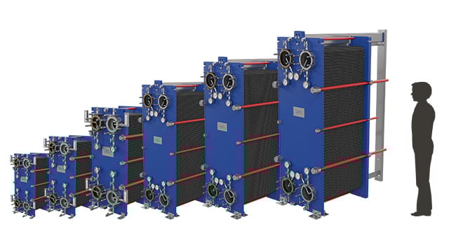
- M3
- M6
- M10
- M15
- M20
- M30
- MX25
- 10
- 10000
- Design Pressure M-Line
- >10 bar (145 psi)
- Marine Engine Room Modelle
- T6 (DN60, 800 kW) bis T35 (DN350, 35.000 kW)
- Marine FSRU Modelle
- TS45, T45, T50 (DN450-500, 45.000-55.000 kW)
- Temperaturbereich Standard
- 0–180°C (depending on model)
- FSRU Temperaturbereich
- -50 bis 150°C
- Plattentypen
- Chevron, Gemini Doppelwand, FlexFlow™
- M-Line (High Pressure Series: M3, M6, M10, M15)
- T-Series (Industrial: T2, T5, T6, T8, T10, T20, T25)
- AQ-Series (HVAC: AQ1, AQ2, AQ3, AQ4, AQ10)
- Marine Line (Engine Room: T6-T35; FSRU: TS45, T45, T50)
- Baseline (Competitive Line)
- Hygienic Line (Premium)
- Area: Gasket wear and embrittlementCheck: Inspect seals visually for cracks, hardening, swelling and discoloration; verify material compatibility with process fluids; check ClipGrip™ fastening. Aging symptoms and loss of elasticity are replacement indicators.
- Area: Clamping dimension and tightness (Tightening Dimension A)Check: Verify A-dimension per manufacturer specifications with caliper (metallic contact required). Keep bolts clean and lubricated. Avoid over-tightening. Perform regular re-tightening after operating hours. At too low A-dimension, pressure loss and leakage are to be expected.
- Area: Fouling and scale formation on plate surfacesCheck: Monitor pressure differential across heat exchanger (increase indicates deposits). Check heat duty versus design value. Optimize CIP intervals after performance audits. Deposits generate higher pump load (energy waste up to 8,000 kWh/year possible).
- Area: Plate corrosion and cracks / breakthroughsCheck: After disassembly, inspect plate surfaces for local measurements (pitting), cracks and perforation corrosion. Verify material compatibility with process fluid. Observe fatigue cracks especially at corners and transitions. When perforation occurs, plate is unrecoverable and must be replaced.
- Area: Pressure test and tightness inspectionCheck: After disassembly and cleaning, perform hydrostatic test per data sheet. Test pressure typically 1.5× operating pressure. Check external and internal leakage at all connections and plate edges. Document findings.
- Area: Plate sequence and alignment (5-point alignment)Check: After opening, verify plate sequence and honeycomb pattern (corrected chevron patterns must alternate). Activate/validate 5-point alignment system for larger units. Offset or misplacement leads to short-circuiting and reduced heat duty.
Type-universal inspection points for Alfa Laval Gasketed Plate Heat Exchangers (GPHE) (Alfa Laval, 2026-06). Per-model specs not auto-populated.
- CB14
- CB26
- CB30
- CB52
- CB76
- CB112
- 5
- 500
- Design Pressure M-Line
- >10 bar (145 psi)
- Marine Engine Room Modelle
- T6 (DN60, 800 kW) bis T35 (DN350, 35.000 kW)
- Marine FSRU Modelle
- TS45, T45, T50 (DN450-500, 45.000-55.000 kW)
- Temperaturbereich Standard
- 0–180°C (depending on model)
- FSRU Temperaturbereich
- -50 bis 150°C
- Plattentypen
- Chevron, Gemini Doppelwand, FlexFlow™
- M-Line (High Pressure Series: M3, M6, M10, M15)
- T-Series (Industrial: T2, T5, T6, T8, T10, T20, T25)
- AQ-Series (HVAC: AQ1, AQ2, AQ3, AQ4, AQ10)
- Marine Line (Engine Room: T6-T35; FSRU: TS45, T45, T50)
- Baseline (Competitive Line)
- Hygienic Line (Premium)
- Area: Gasket wear and embrittlementCheck: Inspect seals visually for cracks, hardening, swelling and discoloration; verify material compatibility with process fluids; check ClipGrip™ fastening. Aging symptoms and loss of elasticity are replacement indicators.
- Area: Clamping dimension and tightness (Tightening Dimension A)Check: Verify A-dimension per manufacturer specifications with caliper (metallic contact required). Keep bolts clean and lubricated. Avoid over-tightening. Perform regular re-tightening after operating hours. At too low A-dimension, pressure loss and leakage are to be expected.
- Area: Fouling and scale formation on plate surfacesCheck: Monitor pressure differential across heat exchanger (increase indicates deposits). Check heat duty versus design value. Optimize CIP intervals after performance audits. Deposits generate higher pump load (energy waste up to 8,000 kWh/year possible).
- Area: Plate corrosion and cracks / breakthroughsCheck: After disassembly, inspect plate surfaces for local measurements (pitting), cracks and perforation corrosion. Verify material compatibility with process fluid. Observe fatigue cracks especially at corners and transitions. When perforation occurs, plate is unrecoverable and must be replaced.
- Area: Pressure test and tightness inspectionCheck: After disassembly and cleaning, perform hydrostatic test per data sheet. Test pressure typically 1.5× operating pressure. Check external and internal leakage at all connections and plate edges. Document findings.
- Area: Plate sequence and alignment (5-point alignment)Check: After opening, verify plate sequence and honeycomb pattern (corrected chevron patterns must alternate). Activate/validate 5-point alignment system for larger units. Offset or misplacement leads to short-circuiting and reduced heat duty.
Type-universal inspection points for Alfa Laval Gasketed Plate Heat Exchangers (GPHE) (Alfa Laval, 2026-06). Per-model specs not auto-populated.
- AlfaNova 14
- AlfaNova 27
- AlfaNova 52
- AlfaNova 76
- 10
- 1000
- Material (CB Series)
- Stainless steel 1.4401 plates, brazed with 100% copper in vacuum furnace
- Material (AlfaNova/AlfaNovaM)
- 100% stainless steel 316 (plates and brazing), patented AlfaFusion™ technology
- Temperature Range (AlfaNova)
- -196°C to 550°C
- Pressure Rating (AlfaNovaM)
- Up to 50 bar
- Design Features
- Gasket-free (brazed) or laser-welded sections; corrugated plate geometry; counter-current flow; single/dual/multi-pass configurations
- Marine Models Available
- AlfaNovaM (HP 27, HP 76, HP 400); CBM series
- CB (Copper-Brazed Series)
- AlfaNova (Fusion-Bonded 100% Stainless Steel)
- AlfaNovaM (Marine-Classified Fusion-Bonded)
- CBM (Copper-Brazed Marine)
- Area: Fouling accumulation (mineral scaling, oil particulates, bio-fouling) reducing thermal efficiency and causing pressure drop increaseCheck: Visual inspection inside heat exchanger after opening plate package; UV light detection—white spots indicate water-soluble scaling, black spots indicate oil-soluble deposits. Monitor pressure drop across unit during operation as early fouling indicator. If fouling detected, perform optimized CIP (Cleaning-in-Place) with custom-formulated cleaning agents (2–4 hours typical duration). Backflushing (3× daily, 30-second pulses) may prevent accumulation.
- Area: Leakage from gasketed interfaces or micro-cracks in plates due to cyclic thermal stress, chemical attack, or pressure fatigueCheck: During operation: inspect for any liquid weeping from gasket glands or plate boundaries—must be zero. Perform periodic integrity testing (recommended every 2 years per Alfa Laval): place donor fluid in primary path, recipient fluid in secondary path, apply positive pressure differential, monitor electronically for donor fluid leakage into secondary circuit. On brazed/fusion-bonded units (CB, AlfaNova), inspect solder/bond lines for microcracks using visual inspection and dye-penetrant testing if available.
- Area: Thermal fatigue and cyclic stress cracking: frequent start-stop cycles and large temperature swings (especially in brazed CB units) cause deformation, gasket blCheck: Monitor inlet and outlet temperature differentials during operation. Document frequency and magnitude of temperature swings. For brazed CB units, be especially cautious—Alfa Laval notes brazed units are sensitive to large, sudden, frequent temperature changes. Inspect solder-joint interfaces during maintenance outages for hairline cracks. Check tightening torque of frame bolts according to Alfa Laval specifications; incorrect bolt load accelerates fatigue. Request Alfa Laval assessment if temperature cycling frequency exceeds design envelope.
- Area: Gasket degradation, cracking, and incompatibility: aging, chemical attack, thermal cycling, and high-temperature volume expansion cause loss of sealing integritCheck: Visually inspect all gasket grooves when plate package is opened—look for cracks, discoloration, swelling, or hardening. Confirm gasket material compatibility with both heat transfer media (check Alfa Laval compatibility matrix). If cracks detected or if unit has been in service >5–7 years, replace gaskets with certified Alfa Laval equivalents using correct groove placement procedure. After replacement, perform torque-down sequence per manual and conduct integrity test before restart.
- Area: Corrosion and pitting of plates, gland seals, and frame components (especially in salt-water marine environments) leading to perforation and contaminationCheck: After opening plate package, inspect plate surfaces under good lighting for pitting, discoloration, or rust staining—prioritize gland/seal areas and plate corners where stagnation may occur. In marine service, perform visual assessment annually or after seasonal lay-ups. For high-corrosion marine duty, verify AlfaNovaM (all-stainless-steel) is in use rather than standard CB (which may have dissimilar metals). Confirm flush/circulation program is followed to prevent salt/sediment accumulation. If pitting observed, consult Alfa Laval on material upgrade or replacement.
- Area: Blockage, clogging, and low shear stress areas in flow channels causing uneven temperature distribution and reduced capacityCheck: Monitor differential temperature across inlet and outlet on each circuit. Uneven temperatures indicate distribution maldistribution or internal blockage. Inspect plate inlet and outlet ports visually for debris or sediment before opening. Compare actual thermal performance (capacity, outlet temperature) against design baseline—significant drop indicates fouling or flow restriction. If blockage suspected in narrow channels, perform flushing with appropriate solvents (per CIP protocol) or request Alfa Laval chemical cleaning. Verify inlet filtration is active to prevent future particulate ingress.
Universal inspection points type for Alfa Laval Brazed & Fusion-Bonded Plate Heat Exchanger (CB / AlfaNova) (Alfa Laval, 2026-06). Per-model specs not auto-filled.
- AQ-2
- AQ-5
- AQ-7
- AQ-10
- AQ-14
- 200
- 15000
- Design Pressure (MD/MC)
- 13-16 bar(g) shell side; up to 13 bar(g) tube side
- Design Temperature Range
- Up to 204-300°C (varies by model; EH-W limited to 95°C)
- Tube Material (MD/MC)
- Cu/Ni 70/30 (MD-T) or Cu/Ni 90/10 (MC) for seawater/corrosive media
- Shell Material
- Carbon steel (custom materials available)
- Thermal Capacity
- 10 kW to ~5000 kW depending on model and configuration
- Standard Certifications
- ABS, DNV, BV, ClassNK marine classification society approved; CE/PED certified
- Aalborg MD (Drain Cooler / Tank Heater / Oil Cooler)
- Aalborg MC (Compact Oil & Steam Cooler)
- Aalborg MX (Compact U-Tube Heater)
- Aalborg EH (Electric Oil Heater)
- Aalborg EH-W (Electric Water Heater)
- Aalborg EH-U (Engine Jacket Water Cooler)
- Aalborg MP-C (Cargo Heater)
- Aalborg ACE (Air-Cooled Finned Tube Heat Exchangers)
- Area: Tube Bundle Fouling (Scale, Deposits, Biological Growth)Check: Visually inspect tube bundle for scaling, sediment, or biofilm deposits. Measure pressure drop across shell and tube sides; marked increase indicates fouling. Advanced inspection: eddy current testing (ECT) or ultrasonic thickness measurement (UT) to assess internal fouling. If fouling present, remove bundle and flush seawater passages with fresh water.
- Area: Tube Corrosion, Pitting, Erosion (Seawater Side)Check: Visually inspect tubes for pitting, erosion marks, or de-zincification (pinkish copper discoloration). Use fluorescent dye (UV light) for microscopic perforation detection. For ferrous tubes: NFT, RFT, MFL, or IRIS testing. For Cu/Ni: Eddy current testing (ECT). Apply ultrasonic thickness mapping (UT) to identify wall thinning and erosion patterns. Check that seawater pressure remains lower than jacket water pressure to prevent seawater intrusion if perforations occur.
- Area: Tube Leakage (Inter-Tube or Tube-to-Tubesheet)Check: Drain both shell and tube sides completely. Visual inspection of tubesheets and nozzles for visible cracks. Apply soap bubble test: pressurize shell side to working pressure, mask one tubesheet completely, apply soapy liquid on opposite side—leaking tubes create bubbles. Alternative: fluorescent dye solution (dissolve sodium crystals in water surrounding tubes, view under UV light for fluorescent halos indicating small leaks). Perform pressure test to confirm repair after remedial work.
- Area: Zinc Anode Depletion & Galvanic CorrosionCheck: Remove and inspect zinc anodes fitted on cover/shell-side. Measure remaining thickness; replace if degraded below ~6 mm. Never use chemical descaler (phosphoric or proprietary acid) while anodes are installed—acids destroy zinc instantly. For seawater-cooled units: ensure sacrificial anode or impressed current cathodic protection (ICCP) system is operational. Check electrical continuity and voltage of ICCP system if installed. Document anode replacement date and condition in log.
- Area: Water-Side Scale & Iron Hydroxide Deposits (Jacket Water)Check: Monitor outlet water color for rust or discoloration (iron oxide formation). If present, drain exchanger and inspect interior shell walls and tube exteriors for reddish-brown deposits. Perform chemical cleaning: isolate unit with shutoff valves, circulate phosphoric acid-based descaler (safe for Cu/Ni) via small pump for 30–90 minutes (avoid proprietary acid during anode presence). Flush thoroughly with fresh water after chemical cleaning. Remove anodes before and refit after chemical treatment. Check cover gaskets for damage and renew if necessary.
- Area: Air-Cooled Fin Fouling & Plugged Header (Charge Air Coolers)Check: For air-cooled units (ACE models): inspect fins visually for salt spray deposits, algae, or debris accumulation (reduces air flow). Check header box plugs for seepage under pressure (Alfa Laval SealTight system reduces this risk). Apply low air-side pressure + soapy water on seawater side to detect leak locations (bubbles form at leaks). Mechanical cleaning: gentle water spray or compressed air. If high plugging risk suspected, inspect plug gaskets and threading. For marine environments, monitor corrosion of aluminum fins and apply protective coatings if necessary.
Type universal inspection points for Alfa Laval Shell-and-Tube & Air-Cooled Heat Exchangers (Marine) (Alfa Laval, 2026-06). Per-model specs not auto-filled.
- Heat-transfer surface fouling, noticed as reduced cooling or heating capacity and increased temperature approach
- Seal or pressure-boundary leakage, causing external seepage or contamination between circuits
- Flow restriction from debris or deposits, indicated by abnormal pressure drop or poor circulation
- Corrosion or erosion of internal heat-transfer surfaces, leading to cross-leakage or unexplained fluid loss
- Air locking or poor venting after maintenance, causing unstable temperatures and reduced effective flow
- Loss of vacuum-side performance from fouling or deposits, noticed as reduced condensing capacity or higher process pressure
- Gasket deterioration or incorrect plate-pack compression, causing external leakage or cross-contamination indications
- Plate or weld damage from corrosion, fatigue or unsuitable media, indicated by mixing of circuits or unexplained level changes
- Air ingress at connections or seals, causing unstable vacuum and reduced condenser performance
- Cooling-water restriction from fouling or blockage, seen as increased temperature approach and reduced heat rejection
- Loss of vacuum-side performance from fouling or deposits, noticed as reduced condensing capacity or higher process pressure
- Gasket deterioration or incorrect plate-pack compression, causing external leakage or cross-contamination indications
- Plate or weld damage from corrosion, fatigue or unsuitable media, indicated by mixing of circuits or unexplained level changes
- Air ingress at connections or seals, causing unstable vacuum and reduced condenser performance
- Cooling-water restriction from fouling or blockage, seen as increased temperature approach and reduced heat rejection
- Loss of vacuum-side performance from fouling or deposits, noticed as reduced condensing capacity or higher process pressure
- Gasket deterioration or incorrect plate-pack compression, causing external leakage or cross-contamination indications
- Plate or weld damage from corrosion, fatigue or unsuitable media, indicated by mixing of circuits or unexplained level changes
- Air ingress at connections or seals, causing unstable vacuum and reduced condenser performance
- Cooling-water restriction from fouling or blockage, seen as increased temperature approach and reduced heat rejection
- Loss of vacuum-side performance from fouling or deposits, noticed as reduced condensing capacity or higher process pressure
- Gasket deterioration or incorrect plate-pack compression, causing external leakage or cross-contamination indications
- Plate or weld damage from corrosion, fatigue or unsuitable media, indicated by mixing of circuits or unexplained level changes
- Air ingress at connections or seals, causing unstable vacuum and reduced condenser performance
- Cooling-water restriction from fouling or blockage, seen as increased temperature approach and reduced heat rejection
- Loss of vacuum-side performance from fouling or deposits, noticed as reduced condensing capacity or higher process pressure
- Gasket deterioration or incorrect plate-pack compression, causing external leakage or cross-contamination indications
- Plate or weld damage from corrosion, fatigue or unsuitable media, indicated by mixing of circuits or unexplained level changes
- Air ingress at connections or seals, causing unstable vacuum and reduced condenser performance
- Cooling-water restriction from fouling or blockage, seen as increased temperature approach and reduced heat rejection
- Loss of vacuum-side performance from fouling or deposits, noticed as reduced condensing capacity or higher process pressure
- Gasket deterioration or incorrect plate-pack compression, causing external leakage or cross-contamination indications
- Plate or weld damage from corrosion, fatigue or unsuitable media, indicated by mixing of circuits or unexplained level changes
- Air ingress at connections or seals, causing unstable vacuum and reduced condenser performance
- Cooling-water restriction from fouling or blockage, seen as increased temperature approach and reduced heat rejection
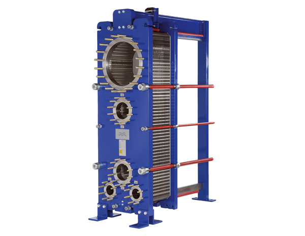
- Loss of vacuum-side performance from fouling or deposits, noticed as reduced condensing capacity or higher process pressure
- Gasket deterioration or incorrect plate-pack compression, causing external leakage or cross-contamination indications
- Plate or weld damage from corrosion, fatigue or unsuitable media, indicated by mixing of circuits or unexplained level changes
- Air ingress at connections or seals, causing unstable vacuum and reduced condenser performance
- Cooling-water restriction from fouling or blockage, seen as increased temperature approach and reduced heat rejection
- Loss of vacuum-side performance from fouling or deposits, noticed as reduced condensing capacity or higher process pressure
- Gasket deterioration or incorrect plate-pack compression, causing external leakage or cross-contamination indications
- Plate or weld damage from corrosion, fatigue or unsuitable media, indicated by mixing of circuits or unexplained level changes
- Air ingress at connections or seals, causing unstable vacuum and reduced condenser performance
- Cooling-water restriction from fouling or blockage, seen as increased temperature approach and reduced heat rejection
- Loss of vacuum-side performance from fouling or deposits, noticed as reduced condensing capacity or higher process pressure
- Gasket deterioration or incorrect plate-pack compression, causing external leakage or cross-contamination indications
- Plate or weld damage from corrosion, fatigue or unsuitable media, indicated by mixing of circuits or unexplained level changes
- Air ingress at connections or seals, causing unstable vacuum and reduced condenser performance
- Cooling-water restriction from fouling or blockage, seen as increased temperature approach and reduced heat rejection
- Loss of vacuum-side performance from fouling or deposits, noticed as reduced condensing capacity or higher process pressure
- Gasket deterioration or incorrect plate-pack compression, causing external leakage or cross-contamination indications
- Plate or weld damage from corrosion, fatigue or unsuitable media, indicated by mixing of circuits or unexplained level changes
- Air ingress at connections or seals, causing unstable vacuum and reduced condenser performance
- Cooling-water restriction from fouling or blockage, seen as increased temperature approach and reduced heat rejection
- Loss of vacuum-side performance from fouling or deposits, noticed as reduced condensing capacity or higher process pressure
- Gasket deterioration or incorrect plate-pack compression, causing external leakage or cross-contamination indications
- Plate or weld damage from corrosion, fatigue or unsuitable media, indicated by mixing of circuits or unexplained level changes
- Air ingress at connections or seals, causing unstable vacuum and reduced condenser performance
- Cooling-water restriction from fouling or blockage, seen as increased temperature approach and reduced heat rejection
- Loss of vacuum-side performance from fouling or deposits, noticed as reduced condensing capacity or higher process pressure
- Gasket deterioration or incorrect plate-pack compression, causing external leakage or cross-contamination indications
- Plate or weld damage from corrosion, fatigue or unsuitable media, indicated by mixing of circuits or unexplained level changes
- Air ingress at connections or seals, causing unstable vacuum and reduced condenser performance
- Cooling-water restriction from fouling or blockage, seen as increased temperature approach and reduced heat rejection
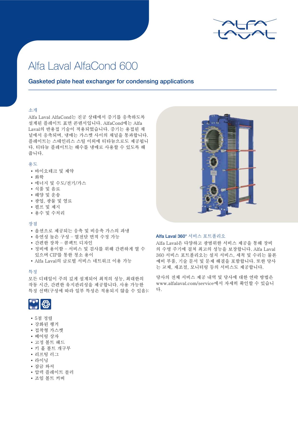
- Loss of vacuum-side performance from fouling or deposits, noticed as reduced condensing capacity or higher process pressure
- Gasket deterioration or incorrect plate-pack compression, causing external leakage or cross-contamination indications
- Plate or weld damage from corrosion, fatigue or unsuitable media, indicated by mixing of circuits or unexplained level changes
- Air ingress at connections or seals, causing unstable vacuum and reduced condenser performance
- Cooling-water restriction from fouling or blockage, seen as increased temperature approach and reduced heat rejection
- Loss of vacuum-side performance from fouling or deposits, noticed as reduced condensing capacity or higher process pressure
- Gasket deterioration or incorrect plate-pack compression, causing external leakage or cross-contamination indications
- Plate or weld damage from corrosion, fatigue or unsuitable media, indicated by mixing of circuits or unexplained level changes
- Air ingress at connections or seals, causing unstable vacuum and reduced condenser performance
- Cooling-water restriction from fouling or blockage, seen as increased temperature approach and reduced heat rejection
- Loss of vacuum-side performance from fouling or deposits, noticed as reduced condensing capacity or higher process pressure
- Gasket deterioration or incorrect plate-pack compression, causing external leakage or cross-contamination indications
- Plate or weld damage from corrosion, fatigue or unsuitable media, indicated by mixing of circuits or unexplained level changes
- Air ingress at connections or seals, causing unstable vacuum and reduced condenser performance
- Cooling-water restriction from fouling or blockage, seen as increased temperature approach and reduced heat rejection
- Loss of vacuum-side performance from fouling or deposits, noticed as reduced condensing capacity or higher process pressure
- Gasket deterioration or incorrect plate-pack compression, causing external leakage or cross-contamination indications
- Plate or weld damage from corrosion, fatigue or unsuitable media, indicated by mixing of circuits or unexplained level changes
- Air ingress at connections or seals, causing unstable vacuum and reduced condenser performance
- Cooling-water restriction from fouling or blockage, seen as increased temperature approach and reduced heat rejection
- Loss of vacuum-side performance from fouling or deposits, noticed as reduced condensing capacity or higher process pressure
- Gasket deterioration or incorrect plate-pack compression, causing external leakage or cross-contamination indications
- Plate or weld damage from corrosion, fatigue or unsuitable media, indicated by mixing of circuits or unexplained level changes
- Air ingress at connections or seals, causing unstable vacuum and reduced condenser performance
- Cooling-water restriction from fouling or blockage, seen as increased temperature approach and reduced heat rejection
- Loss of vacuum-side performance from fouling or deposits, noticed as reduced condensing capacity or higher process pressure
- Gasket deterioration or incorrect plate-pack compression, causing external leakage or cross-contamination indications
- Plate or weld damage from corrosion, fatigue or unsuitable media, indicated by mixing of circuits or unexplained level changes
- Air ingress at connections or seals, causing unstable vacuum and reduced condenser performance
- Cooling-water restriction from fouling or blockage, seen as increased temperature approach and reduced heat rejection
- Loss of vacuum-side performance from fouling or deposits, noticed as reduced condensing capacity or higher process pressure
- Gasket deterioration or incorrect plate-pack compression, causing external leakage or cross-contamination indications
- Plate or weld damage from corrosion, fatigue or unsuitable media, indicated by mixing of circuits or unexplained level changes
- Air ingress at connections or seals, causing unstable vacuum and reduced condenser performance
- Cooling-water restriction from fouling or blockage, seen as increased temperature approach and reduced heat rejection
- Loss of vacuum-side performance from fouling or deposits, noticed as reduced condensing capacity or higher process pressure
- Gasket deterioration or incorrect plate-pack compression, causing external leakage or cross-contamination indications
- Plate or weld damage from corrosion, fatigue or unsuitable media, indicated by mixing of circuits or unexplained level changes
- Air ingress at connections or seals, causing unstable vacuum and reduced condenser performance
- Cooling-water restriction from fouling or blockage, seen as increased temperature approach and reduced heat rejection
- Loss of vacuum-side performance from fouling or deposits, noticed as reduced condensing capacity or higher process pressure
- Gasket deterioration or incorrect plate-pack compression, causing external leakage or cross-contamination indications
- Plate or weld damage from corrosion, fatigue or unsuitable media, indicated by mixing of circuits or unexplained level changes
- Air ingress at connections or seals, causing unstable vacuum and reduced condenser performance
- Cooling-water restriction from fouling or blockage, seen as increased temperature approach and reduced heat rejection
- Loss of vacuum-side performance from fouling or deposits, noticed as reduced condensing capacity or higher process pressure
- Gasket deterioration or incorrect plate-pack compression, causing external leakage or cross-contamination indications
- Plate or weld damage from corrosion, fatigue or unsuitable media, indicated by mixing of circuits or unexplained level changes
- Air ingress at connections or seals, causing unstable vacuum and reduced condenser performance
- Cooling-water restriction from fouling or blockage, seen as increased temperature approach and reduced heat rejection
- Loss of vacuum-side performance from fouling or deposits, noticed as reduced condensing capacity or higher process pressure
- Gasket deterioration or incorrect plate-pack compression, causing external leakage or cross-contamination indications
- Plate or weld damage from corrosion, fatigue or unsuitable media, indicated by mixing of circuits or unexplained level changes
- Air ingress at connections or seals, causing unstable vacuum and reduced condenser performance
- Cooling-water restriction from fouling or blockage, seen as increased temperature approach and reduced heat rejection
- Loss of vacuum-side performance from fouling or deposits, noticed as reduced condensing capacity or higher process pressure
- Gasket deterioration or incorrect plate-pack compression, causing external leakage or cross-contamination indications
- Plate or weld damage from corrosion, fatigue or unsuitable media, indicated by mixing of circuits or unexplained level changes
- Air ingress at connections or seals, causing unstable vacuum and reduced condenser performance
- Cooling-water restriction from fouling or blockage, seen as increased temperature approach and reduced heat rejection
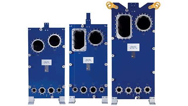
- Product-side fouling or scaling, noticed as falling evaporation rate, rising temperature difference or reduced throughput
- Gasket degradation from age, chemicals or incorrect assembly, causing external leakage or process contamination
- Plate-cassette damage or weld leakage, indicated by cross-contamination between steam/condensate and product circuits
- Poor distribution or restricted feed flow, causing unstable evaporation, local overheating or vibration
- Steam-side contamination or condensate drainage problems, seen as reduced heating performance and erratic process temperatures
- Product-side fouling or scaling, noticed as falling evaporation rate, rising temperature difference or reduced throughput
- Gasket degradation from age, chemicals or incorrect assembly, causing external leakage or process contamination
- Plate-cassette damage or weld leakage, indicated by cross-contamination between steam/condensate and product circuits
- Poor distribution or restricted feed flow, causing unstable evaporation, local overheating or vibration
- Steam-side contamination or condensate drainage problems, seen as reduced heating performance and erratic process temperatures
- Product-side fouling or scaling, noticed as falling evaporation rate, rising temperature difference or reduced throughput
- Gasket degradation from age, chemicals or incorrect assembly, causing external leakage or process contamination
- Plate-cassette damage or weld leakage, indicated by cross-contamination between steam/condensate and product circuits
- Poor distribution or restricted feed flow, causing unstable evaporation, local overheating or vibration
- Steam-side contamination or condensate drainage problems, seen as reduced heating performance and erratic process temperatures
- Product-side fouling or scaling, noticed as falling evaporation rate, rising temperature difference or reduced throughput
- Gasket degradation from age, chemicals or incorrect assembly, causing external leakage or process contamination
- Plate-cassette damage or weld leakage, indicated by cross-contamination between steam/condensate and product circuits
- Poor distribution or restricted feed flow, causing unstable evaporation, local overheating or vibration
- Steam-side contamination or condensate drainage problems, seen as reduced heating performance and erratic process temperatures
- Product-side fouling or scaling, noticed as falling evaporation rate, rising temperature difference or reduced throughput
- Gasket degradation from age, chemicals or incorrect assembly, causing external leakage or process contamination
- Plate-cassette damage or weld leakage, indicated by cross-contamination between steam/condensate and product circuits
- Poor distribution or restricted feed flow, causing unstable evaporation, local overheating or vibration
- Steam-side contamination or condensate drainage problems, seen as reduced heating performance and erratic process temperatures
- Product-side fouling or scaling, noticed as falling evaporation rate, rising temperature difference or reduced throughput
- Gasket degradation from age, chemicals or incorrect assembly, causing external leakage or process contamination
- Plate-cassette damage or weld leakage, indicated by cross-contamination between steam/condensate and product circuits
- Poor distribution or restricted feed flow, causing unstable evaporation, local overheating or vibration
- Steam-side contamination or condensate drainage problems, seen as reduced heating performance and erratic process temperatures
- Product-side fouling or scaling, noticed as falling evaporation rate, rising temperature difference or reduced throughput
- Gasket degradation from age, chemicals or incorrect assembly, causing external leakage or process contamination
- Plate-cassette damage or weld leakage, indicated by cross-contamination between steam/condensate and product circuits
- Poor distribution or restricted feed flow, causing unstable evaporation, local overheating or vibration
- Steam-side contamination or condensate drainage problems, seen as reduced heating performance and erratic process temperatures
- Product-side fouling or scaling, noticed as falling evaporation rate, rising temperature difference or reduced throughput
- Gasket degradation from age, chemicals or incorrect assembly, causing external leakage or process contamination
- Plate-cassette damage or weld leakage, indicated by cross-contamination between steam/condensate and product circuits
- Poor distribution or restricted feed flow, causing unstable evaporation, local overheating or vibration
- Steam-side contamination or condensate drainage problems, seen as reduced heating performance and erratic process temperatures
- Product-side fouling or scaling, noticed as falling evaporation rate, rising temperature difference or reduced throughput
- Gasket degradation from age, chemicals or incorrect assembly, causing external leakage or process contamination
- Plate-cassette damage or weld leakage, indicated by cross-contamination between steam/condensate and product circuits
- Poor distribution or restricted feed flow, causing unstable evaporation, local overheating or vibration
- Steam-side contamination or condensate drainage problems, seen as reduced heating performance and erratic process temperatures
- Product-side fouling or scaling, noticed as falling evaporation rate, rising temperature difference or reduced throughput
- Gasket degradation from age, chemicals or incorrect assembly, causing external leakage or process contamination
- Plate-cassette damage or weld leakage, indicated by cross-contamination between steam/condensate and product circuits
- Poor distribution or restricted feed flow, causing unstable evaporation, local overheating or vibration
- Steam-side contamination or condensate drainage problems, seen as reduced heating performance and erratic process temperatures
- Product-side fouling or scaling, noticed as falling evaporation rate, rising temperature difference or reduced throughput
- Gasket degradation from age, chemicals or incorrect assembly, causing external leakage or process contamination
- Plate-cassette damage or weld leakage, indicated by cross-contamination between steam/condensate and product circuits
- Poor distribution or restricted feed flow, causing unstable evaporation, local overheating or vibration
- Steam-side contamination or condensate drainage problems, seen as reduced heating performance and erratic process temperatures
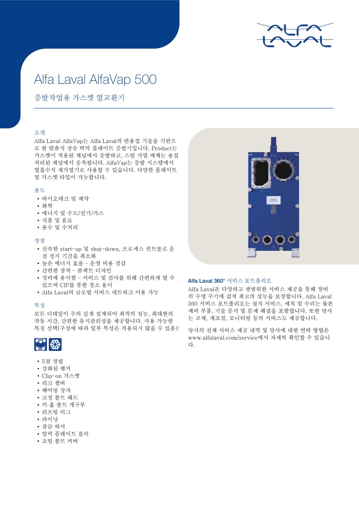
- Product-side fouling or scaling, noticed as falling evaporation rate, rising temperature difference or reduced throughput
- Gasket degradation from age, chemicals or incorrect assembly, causing external leakage or process contamination
- Plate-cassette damage or weld leakage, indicated by cross-contamination between steam/condensate and product circuits
- Poor distribution or restricted feed flow, causing unstable evaporation, local overheating or vibration
- Steam-side contamination or condensate drainage problems, seen as reduced heating performance and erratic process temperatures
- Product-side fouling or scaling, noticed as falling evaporation rate, rising temperature difference or reduced throughput
- Gasket degradation from age, chemicals or incorrect assembly, causing external leakage or process contamination
- Plate-cassette damage or weld leakage, indicated by cross-contamination between steam/condensate and product circuits
- Poor distribution or restricted feed flow, causing unstable evaporation, local overheating or vibration
- Steam-side contamination or condensate drainage problems, seen as reduced heating performance and erratic process temperatures
- Product-side fouling or scaling, noticed as falling evaporation rate, rising temperature difference or reduced throughput
- Gasket degradation from age, chemicals or incorrect assembly, causing external leakage or process contamination
- Plate-cassette damage or weld leakage, indicated by cross-contamination between steam/condensate and product circuits
- Poor distribution or restricted feed flow, causing unstable evaporation, local overheating or vibration
- Steam-side contamination or condensate drainage problems, seen as reduced heating performance and erratic process temperatures
- Product-side fouling or scaling, noticed as falling evaporation rate, rising temperature difference or reduced throughput
- Gasket degradation from age, chemicals or incorrect assembly, causing external leakage or process contamination
- Plate-cassette damage or weld leakage, indicated by cross-contamination between steam/condensate and product circuits
- Poor distribution or restricted feed flow, causing unstable evaporation, local overheating or vibration
- Steam-side contamination or condensate drainage problems, seen as reduced heating performance and erratic process temperatures
- Product-side fouling or scaling, noticed as falling evaporation rate, rising temperature difference or reduced throughput
- Gasket degradation from age, chemicals or incorrect assembly, causing external leakage or process contamination
- Plate-cassette damage or weld leakage, indicated by cross-contamination between steam/condensate and product circuits
- Poor distribution or restricted feed flow, causing unstable evaporation, local overheating or vibration
- Steam-side contamination or condensate drainage problems, seen as reduced heating performance and erratic process temperatures
- Product-side fouling or scaling, noticed as falling evaporation rate, rising temperature difference or reduced throughput
- Gasket degradation from age, chemicals or incorrect assembly, causing external leakage or process contamination
- Plate-cassette damage or weld leakage, indicated by cross-contamination between steam/condensate and product circuits
- Poor distribution or restricted feed flow, causing unstable evaporation, local overheating or vibration
- Steam-side contamination or condensate drainage problems, seen as reduced heating performance and erratic process temperatures
- Product-side fouling or scaling, noticed as falling evaporation rate, rising temperature difference or reduced throughput
- Gasket degradation from age, chemicals or incorrect assembly, causing external leakage or process contamination
- Plate-cassette damage or weld leakage, indicated by cross-contamination between steam/condensate and product circuits
- Poor distribution or restricted feed flow, causing unstable evaporation, local overheating or vibration
- Steam-side contamination or condensate drainage problems, seen as reduced heating performance and erratic process temperatures
- Product-side fouling or scaling, noticed as falling evaporation rate, rising temperature difference or reduced throughput
- Gasket degradation from age, chemicals or incorrect assembly, causing external leakage or process contamination
- Plate-cassette damage or weld leakage, indicated by cross-contamination between steam/condensate and product circuits
- Poor distribution or restricted feed flow, causing unstable evaporation, local overheating or vibration
- Steam-side contamination or condensate drainage problems, seen as reduced heating performance and erratic process temperatures
- Product-side fouling or scaling, noticed as falling evaporation rate, rising temperature difference or reduced throughput
- Gasket degradation from age, chemicals or incorrect assembly, causing external leakage or process contamination
- Plate-cassette damage or weld leakage, indicated by cross-contamination between steam/condensate and product circuits
- Poor distribution or restricted feed flow, causing unstable evaporation, local overheating or vibration
- Steam-side contamination or condensate drainage problems, seen as reduced heating performance and erratic process temperatures
- Product-side fouling or scaling, noticed as falling evaporation rate, rising temperature difference or reduced throughput
- Gasket degradation from age, chemicals or incorrect assembly, causing external leakage or process contamination
- Plate-cassette damage or weld leakage, indicated by cross-contamination between steam/condensate and product circuits
- Poor distribution or restricted feed flow, causing unstable evaporation, local overheating or vibration
- Steam-side contamination or condensate drainage problems, seen as reduced heating performance and erratic process temperatures
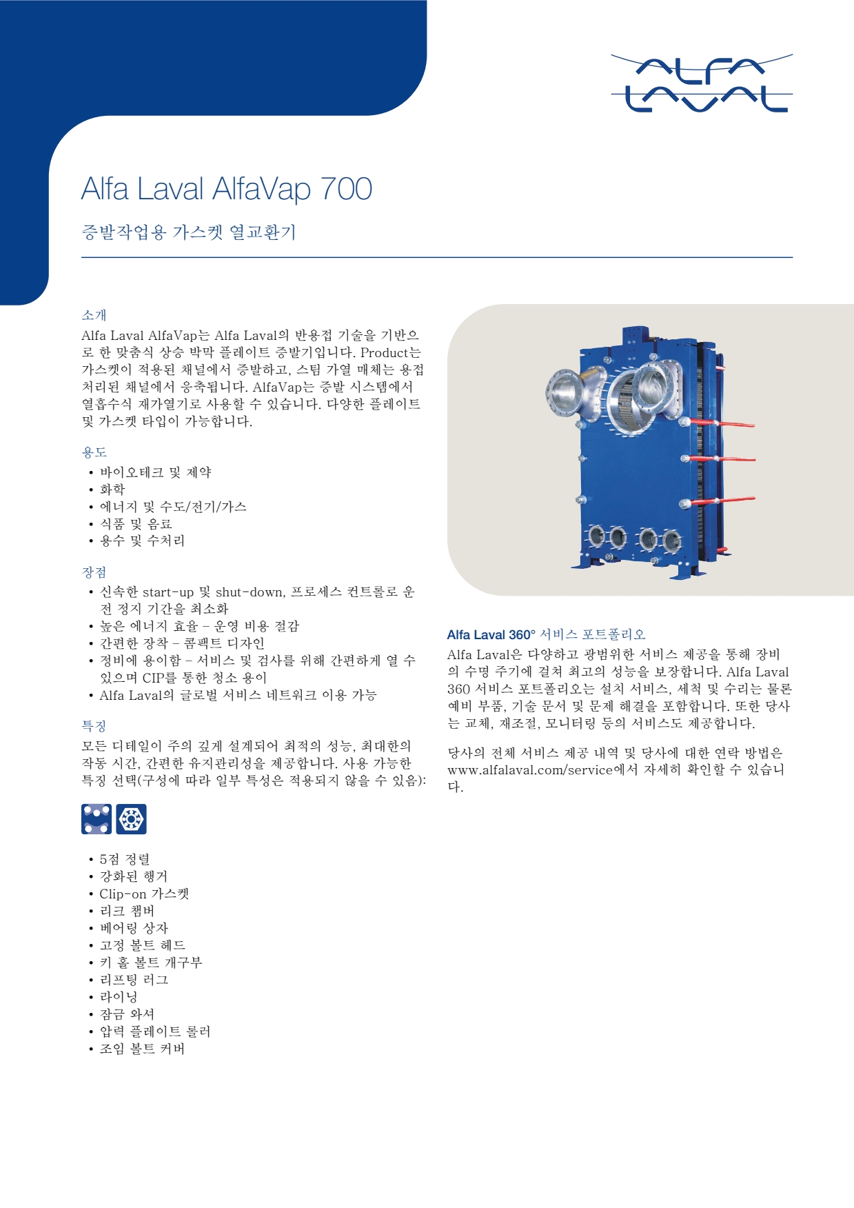
- Product-side fouling or scaling, noticed as falling evaporation rate, rising temperature difference or reduced throughput
- Gasket degradation from age, chemicals or incorrect assembly, causing external leakage or process contamination
- Plate-cassette damage or weld leakage, indicated by cross-contamination between steam/condensate and product circuits
- Poor distribution or restricted feed flow, causing unstable evaporation, local overheating or vibration
- Steam-side contamination or condensate drainage problems, seen as reduced heating performance and erratic process temperatures
- Product-side fouling or scaling, noticed as falling evaporation rate, rising temperature difference or reduced throughput
- Gasket degradation from age, chemicals or incorrect assembly, causing external leakage or process contamination
- Plate-cassette damage or weld leakage, indicated by cross-contamination between steam/condensate and product circuits
- Poor distribution or restricted feed flow, causing unstable evaporation, local overheating or vibration
- Steam-side contamination or condensate drainage problems, seen as reduced heating performance and erratic process temperatures
- Product-side fouling or scaling, noticed as falling evaporation rate, rising temperature difference or reduced throughput
- Gasket degradation from age, chemicals or incorrect assembly, causing external leakage or process contamination
- Plate-cassette damage or weld leakage, indicated by cross-contamination between steam/condensate and product circuits
- Poor distribution or restricted feed flow, causing unstable evaporation, local overheating or vibration
- Steam-side contamination or condensate drainage problems, seen as reduced heating performance and erratic process temperatures
- Fouling in process channels from dirty or polymerising media, noticed as increasing pressure drop and loss of thermal performance
- Internal plate or weld leakage from corrosion, fatigue or incompatible media, indicated by cross-contamination between circuits
- Cover-gasket leakage after ageing, incorrect assembly or thermal cycling, seen as external seepage at the casing
- Flow maldistribution or blocked passages, causing uneven outlet temperatures and reduced duty
- Corrosion at covers, nozzles or pressure-retaining parts where coating, material selection or drainage is inadequate
- Fouling in process channels from dirty or polymerising media, noticed as increasing pressure drop and loss of thermal performance
- Internal plate or weld leakage from corrosion, fatigue or incompatible media, indicated by cross-contamination between circuits
- Cover-gasket leakage after ageing, incorrect assembly or thermal cycling, seen as external seepage at the casing
- Flow maldistribution or blocked passages, causing uneven outlet temperatures and reduced duty
- Corrosion at covers, nozzles or pressure-retaining parts where coating, material selection or drainage is inadequate
- Fouling in process channels from dirty or polymerising media, noticed as increasing pressure drop and loss of thermal performance
- Internal plate or weld leakage from corrosion, fatigue or incompatible media, indicated by cross-contamination between circuits
- Cover-gasket leakage after ageing, incorrect assembly or thermal cycling, seen as external seepage at the casing
- Flow maldistribution or blocked passages, causing uneven outlet temperatures and reduced duty
- Corrosion at covers, nozzles or pressure-retaining parts where coating, material selection or drainage is inadequate
- Fouling in process channels from dirty or polymerising media, noticed as increasing pressure drop and loss of thermal performance
- Internal plate or weld leakage from corrosion, fatigue or incompatible media, indicated by cross-contamination between circuits
- Cover-gasket leakage after ageing, incorrect assembly or thermal cycling, seen as external seepage at the casing
- Flow maldistribution or blocked passages, causing uneven outlet temperatures and reduced duty
- Corrosion at covers, nozzles or pressure-retaining parts where coating, material selection or drainage is inadequate
- Fouling in process channels from dirty or polymerising media, noticed as increasing pressure drop and loss of thermal performance
- Internal plate or weld leakage from corrosion, fatigue or incompatible media, indicated by cross-contamination between circuits
- Cover-gasket leakage after ageing, incorrect assembly or thermal cycling, seen as external seepage at the casing
- Flow maldistribution or blocked passages, causing uneven outlet temperatures and reduced duty
- Corrosion at covers, nozzles or pressure-retaining parts where coating, material selection or drainage is inadequate
- Fouling in process channels from dirty or polymerising media, noticed as increasing pressure drop and loss of thermal performance
- Internal plate or weld leakage from corrosion, fatigue or incompatible media, indicated by cross-contamination between circuits
- Cover-gasket leakage after ageing, incorrect assembly or thermal cycling, seen as external seepage at the casing
- Flow maldistribution or blocked passages, causing uneven outlet temperatures and reduced duty
- Corrosion at covers, nozzles or pressure-retaining parts where coating, material selection or drainage is inadequate
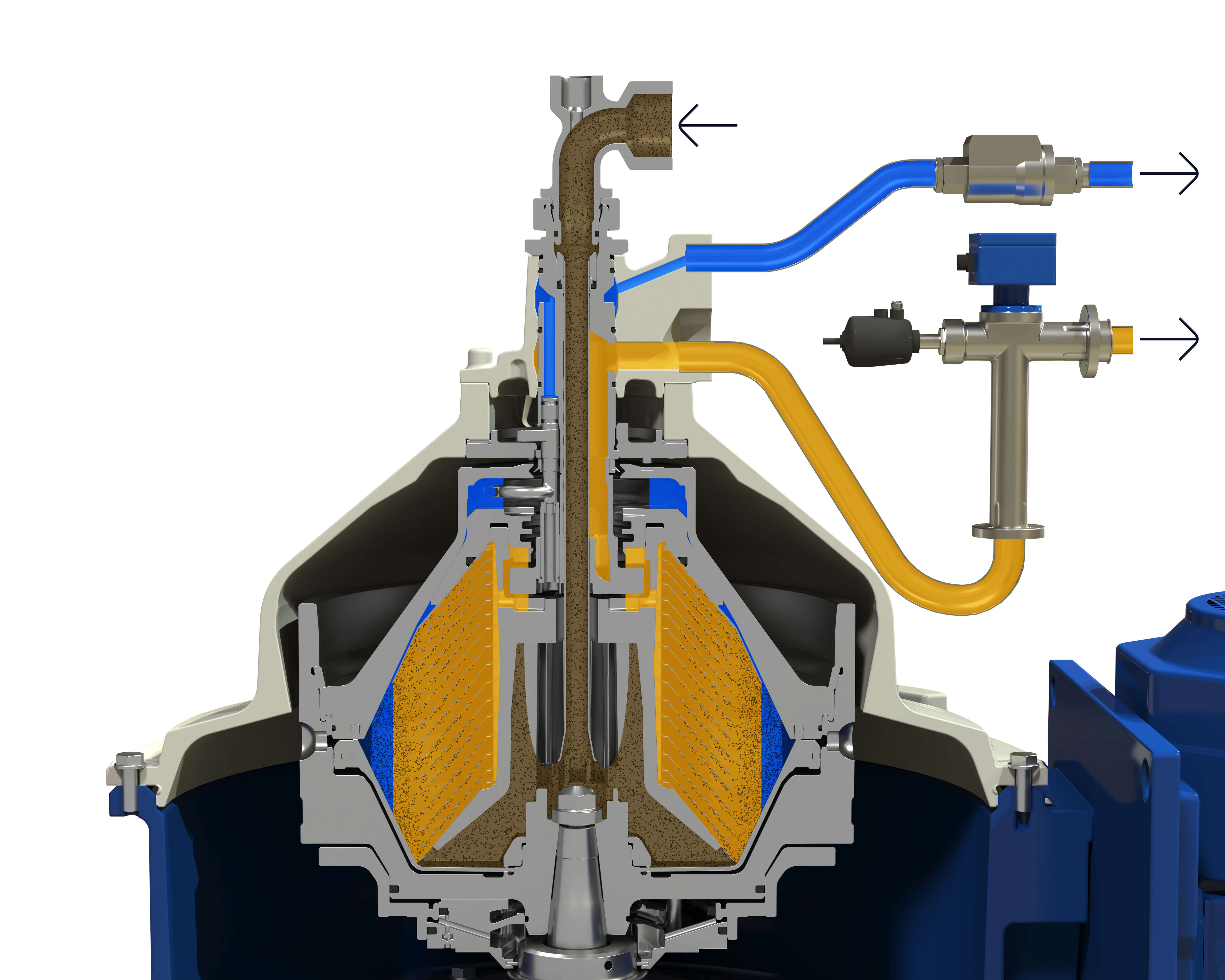
- Fouling in process channels from dirty or polymerising media, noticed as increasing pressure drop and loss of thermal performance
- Internal plate or weld leakage from corrosion, fatigue or incompatible media, indicated by cross-contamination between circuits
- Cover-gasket leakage after ageing, incorrect assembly or thermal cycling, seen as external seepage at the casing
- Flow maldistribution or blocked passages, causing uneven outlet temperatures and reduced duty
- Corrosion at covers, nozzles or pressure-retaining parts where coating, material selection or drainage is inadequate
- Internal fouling or contamination on the fluid side, producing reduced heat transfer and increased pressure drop
- Restricted refrigerant or liquid distribution, producing uneven temperature profiles, poor capacity or unstable system operation
- Freezing or abnormal thermal stress caused by unsuitable operating conditions, producing loss of performance or possible internal damage
- External corrosion, vibration damage or stressed pipe connections, producing leakage at joints or connections
- Internal leakage caused by plate or braze damage, producing cross-contamination, loss of refrigerant or abnormal system pressures
- Internal fouling or contamination on the fluid side, producing reduced heat transfer and increased pressure drop
- Restricted refrigerant or liquid distribution, producing uneven temperature profiles, poor capacity or unstable system operation
- Freezing or abnormal thermal stress caused by unsuitable operating conditions, producing loss of performance or possible internal damage
- External corrosion, vibration damage or stressed pipe connections, producing leakage at joints or connections
- Internal leakage caused by plate or braze damage, producing cross-contamination, loss of refrigerant or abnormal system pressures
- Internal fouling or contamination on the fluid side, producing reduced heat transfer and increased pressure drop
- Restricted refrigerant or liquid distribution, producing uneven temperature profiles, poor capacity or unstable system operation
- Freezing or abnormal thermal stress caused by unsuitable operating conditions, producing loss of performance or possible internal damage
- External corrosion, vibration damage or stressed pipe connections, producing leakage at joints or connections
- Internal leakage caused by plate or braze damage, producing cross-contamination, loss of refrigerant or abnormal system pressures
- Internal fouling or contamination on the fluid side, producing reduced heat transfer and increased pressure drop
- Restricted refrigerant or liquid distribution, producing uneven temperature profiles, poor capacity or unstable system operation
- Freezing or abnormal thermal stress caused by unsuitable operating conditions, producing loss of performance or possible internal damage
- External corrosion, vibration damage or stressed pipe connections, producing leakage at joints or connections
- Internal leakage caused by plate or braze damage, producing cross-contamination, loss of refrigerant or abnormal system pressures
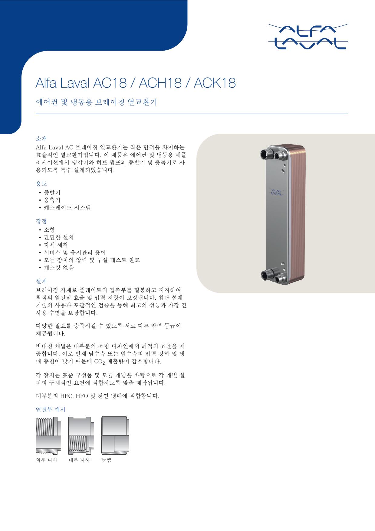
- Internal fouling or contamination on the fluid side, producing reduced heat transfer and increased pressure drop
- Restricted refrigerant or liquid distribution, producing uneven temperature profiles, poor capacity or unstable system operation
- Freezing or abnormal thermal stress caused by unsuitable operating conditions, producing loss of performance or possible internal damage
- External corrosion, vibration damage or stressed pipe connections, producing leakage at joints or connections
- Internal leakage caused by plate or braze damage, producing cross-contamination, loss of refrigerant or abnormal system pressures
- Internal fouling or contamination on the fluid side, producing reduced heat transfer and increased pressure drop
- Restricted refrigerant or liquid distribution, producing uneven temperature profiles, poor capacity or unstable system operation
- Freezing or abnormal thermal stress caused by unsuitable operating conditions, producing loss of performance or possible internal damage
- External corrosion, vibration damage or stressed pipe connections, producing leakage at joints or connections
- Internal leakage caused by plate or braze damage, producing cross-contamination, loss of refrigerant or abnormal system pressures
- Internal fouling or contamination on the fluid side, producing reduced heat transfer and increased pressure drop
- Restricted refrigerant or liquid distribution, producing uneven temperature profiles, poor capacity or unstable system operation
- Freezing or abnormal thermal stress caused by unsuitable operating conditions, producing loss of performance or possible internal damage
- External corrosion, vibration damage or stressed pipe connections, producing leakage at joints or connections
- Internal leakage caused by plate or braze damage, producing cross-contamination, loss of refrigerant or abnormal system pressures
- Internal fouling or contamination on the fluid side, producing reduced heat transfer and increased pressure drop
- Restricted refrigerant or liquid distribution, producing uneven temperature profiles, poor capacity or unstable system operation
- Freezing or abnormal thermal stress caused by unsuitable operating conditions, producing loss of performance or possible internal damage
- External corrosion, vibration damage or stressed pipe connections, producing leakage at joints or connections
- Internal leakage caused by plate or braze damage, producing cross-contamination, loss of refrigerant or abnormal system pressures
- Internal fouling or contamination on the fluid side, producing reduced heat transfer and increased pressure drop
- Restricted refrigerant or liquid distribution, producing uneven temperature profiles, poor capacity or unstable system operation
- Freezing or abnormal thermal stress caused by unsuitable operating conditions, producing loss of performance or possible internal damage
- External corrosion, vibration damage or stressed pipe connections, producing leakage at joints or connections
- Internal leakage caused by plate or braze damage, producing cross-contamination, loss of refrigerant or abnormal system pressures
- Internal fouling or contamination on the fluid side, producing reduced heat transfer and increased pressure drop
- Restricted refrigerant or liquid distribution, producing uneven temperature profiles, poor capacity or unstable system operation
- Freezing or abnormal thermal stress caused by unsuitable operating conditions, producing loss of performance or possible internal damage
- External corrosion, vibration damage or stressed pipe connections, producing leakage at joints or connections
- Internal leakage caused by plate or braze damage, producing cross-contamination, loss of refrigerant or abnormal system pressures
- Internal fouling or contamination on the fluid side, producing reduced heat transfer and increased pressure drop
- Restricted refrigerant or liquid distribution, producing uneven temperature profiles, poor capacity or unstable system operation
- Freezing or abnormal thermal stress caused by unsuitable operating conditions, producing loss of performance or possible internal damage
- External corrosion, vibration damage or stressed pipe connections, producing leakage at joints or connections
- Internal leakage caused by plate or braze damage, producing cross-contamination, loss of refrigerant or abnormal system pressures
- Internal fouling or contamination on the fluid side, producing reduced heat transfer and increased pressure drop
- Restricted refrigerant or liquid distribution, producing uneven temperature profiles, poor capacity or unstable system operation
- Freezing or abnormal thermal stress caused by unsuitable operating conditions, producing loss of performance or possible internal damage
- External corrosion, vibration damage or stressed pipe connections, producing leakage at joints or connections
- Internal leakage caused by plate or braze damage, producing cross-contamination, loss of refrigerant or abnormal system pressures
- Internal fouling or contamination on the fluid side, producing reduced heat transfer and increased pressure drop
- Restricted refrigerant or liquid distribution, producing uneven temperature profiles, poor capacity or unstable system operation
- Freezing or abnormal thermal stress caused by unsuitable operating conditions, producing loss of performance or possible internal damage
- External corrosion, vibration damage or stressed pipe connections, producing leakage at joints or connections
- Internal leakage caused by plate or braze damage, producing cross-contamination, loss of refrigerant or abnormal system pressures
- Internal fouling or contamination on the fluid side, producing reduced heat transfer and increased pressure drop
- Restricted refrigerant or liquid distribution, producing uneven temperature profiles, poor capacity or unstable system operation
- Freezing or abnormal thermal stress caused by unsuitable operating conditions, producing loss of performance or possible internal damage
- External corrosion, vibration damage or stressed pipe connections, producing leakage at joints or connections
- Internal leakage caused by plate or braze damage, producing cross-contamination, loss of refrigerant or abnormal system pressures
- Internal fouling or contamination on the fluid side, producing reduced heat transfer and increased pressure drop
- Restricted refrigerant or liquid distribution, producing uneven temperature profiles, poor capacity or unstable system operation
- Freezing or abnormal thermal stress caused by unsuitable operating conditions, producing loss of performance or possible internal damage
- External corrosion, vibration damage or stressed pipe connections, producing leakage at joints or connections
- Internal leakage caused by plate or braze damage, producing cross-contamination, loss of refrigerant or abnormal system pressures
- Internal fouling or contamination on the fluid side, producing reduced heat transfer and increased pressure drop
- Restricted refrigerant or liquid distribution, producing uneven temperature profiles, poor capacity or unstable system operation
- Freezing or abnormal thermal stress caused by unsuitable operating conditions, producing loss of performance or possible internal damage
- External corrosion, vibration damage or stressed pipe connections, producing leakage at joints or connections
- Internal leakage caused by plate or braze damage, producing cross-contamination, loss of refrigerant or abnormal system pressures
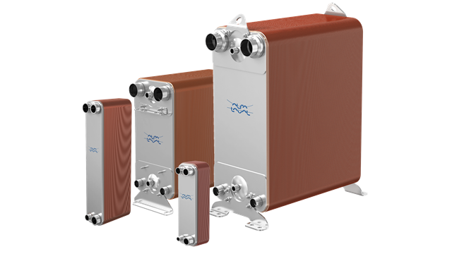
- Internal fouling or contamination on the fluid side, producing reduced heat transfer and increased pressure drop
- Restricted refrigerant or liquid distribution, producing uneven temperature profiles, poor capacity or unstable system operation
- Freezing or abnormal thermal stress caused by unsuitable operating conditions, producing loss of performance or possible internal damage
- External corrosion, vibration damage or stressed pipe connections, producing leakage at joints or connections
- Internal leakage caused by plate or braze damage, producing cross-contamination, loss of refrigerant or abnormal system pressures
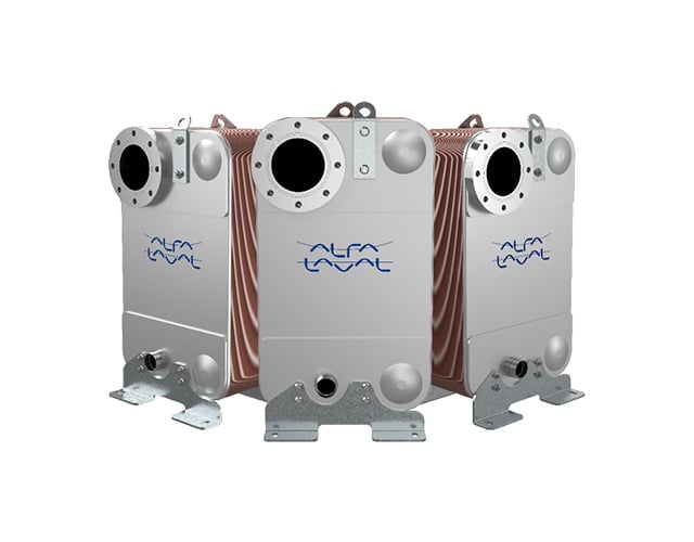
- Internal fouling or contamination on the fluid side, producing reduced heat transfer and increased pressure drop
- Restricted refrigerant or liquid distribution, producing uneven temperature profiles, poor capacity or unstable system operation
- Freezing or abnormal thermal stress caused by unsuitable operating conditions, producing loss of performance or possible internal damage
- External corrosion, vibration damage or stressed pipe connections, producing leakage at joints or connections
- Internal leakage caused by plate or braze damage, producing cross-contamination, loss of refrigerant or abnormal system pressures
- Internal fouling or contamination on the fluid side, producing reduced heat transfer and increased pressure drop
- Restricted refrigerant or liquid distribution, producing uneven temperature profiles, poor capacity or unstable system operation
- Freezing or abnormal thermal stress caused by unsuitable operating conditions, producing loss of performance or possible internal damage
- External corrosion, vibration damage or stressed pipe connections, producing leakage at joints or connections
- Internal leakage caused by plate or braze damage, producing cross-contamination, loss of refrigerant or abnormal system pressures
- Internal fouling or contamination on the fluid side, producing reduced heat transfer and increased pressure drop
- Restricted refrigerant or liquid distribution, producing uneven temperature profiles, poor capacity or unstable system operation
- Freezing or abnormal thermal stress caused by unsuitable operating conditions, producing loss of performance or possible internal damage
- External corrosion, vibration damage or stressed pipe connections, producing leakage at joints or connections
- Internal leakage caused by plate or braze damage, producing cross-contamination, loss of refrigerant or abnormal system pressures
- Internal fouling or contamination on the fluid side, producing reduced heat transfer and increased pressure drop
- Restricted refrigerant or liquid distribution, producing uneven temperature profiles, poor capacity or unstable system operation
- Freezing or abnormal thermal stress caused by unsuitable operating conditions, producing loss of performance or possible internal damage
- External corrosion, vibration damage or stressed pipe connections, producing leakage at joints or connections
- Internal leakage caused by plate or braze damage, producing cross-contamination, loss of refrigerant or abnormal system pressures
- Internal fouling or contamination on the fluid side, producing reduced heat transfer and increased pressure drop
- Restricted refrigerant or liquid distribution, producing uneven temperature profiles, poor capacity or unstable system operation
- Freezing or abnormal thermal stress caused by unsuitable operating conditions, producing loss of performance or possible internal damage
- External corrosion, vibration damage or stressed pipe connections, producing leakage at joints or connections
- Internal leakage caused by plate or braze damage, producing cross-contamination, loss of refrigerant or abnormal system pressures
- Internal fouling caused by contaminated water, oil or process fluid, indicated by reduced heat-transfer capacity and increasing pressure drop
- Flow restriction caused by debris, deposits or blocked upstream strainers, indicated by low flow and abnormal operating pressures or temperatures
- External leakage at connections or brazed joints caused by corrosion, vibration or piping stress, indicated by visible fluid, oil traces or loss of refrigerant charge
- Internal cross-leakage caused by plate or brazed-joint failure, indicated by contamination between circuits or unexplained loss from one side
- Freeze damage in evaporator or chilled-fluid service caused by inadequate flow or control malfunction, indicated by sudden leakage or loss of pressure integrity
- Refrigerant maldistribution or unstable control caused by system-side faults, indicated by fluctuating superheat, capacity or discharge conditions
- Internal fouling caused by contaminated water, oil or process fluid, indicated by reduced heat-transfer capacity and increasing pressure drop
- Flow restriction caused by debris, deposits or blocked upstream strainers, indicated by low flow and abnormal operating pressures or temperatures
- External leakage at connections or brazed joints caused by corrosion, vibration or piping stress, indicated by visible fluid, oil traces or loss of refrigerant charge
- Internal cross-leakage caused by plate or brazed-joint failure, indicated by contamination between circuits or unexplained loss from one side
- Freeze damage in evaporator or chilled-fluid service caused by inadequate flow or control malfunction, indicated by sudden leakage or loss of pressure integrity
- Refrigerant maldistribution or unstable control caused by system-side faults, indicated by fluctuating superheat, capacity or discharge conditions
- Internal fouling caused by contaminated water, oil or process fluid, indicated by reduced heat-transfer capacity and increasing pressure drop
- Flow restriction caused by debris, deposits or blocked upstream strainers, indicated by low flow and abnormal operating pressures or temperatures
- External leakage at connections or brazed joints caused by corrosion, vibration or piping stress, indicated by visible fluid, oil traces or loss of refrigerant charge
- Internal cross-leakage caused by plate or brazed-joint failure, indicated by contamination between circuits or unexplained loss from one side
- Freeze damage in evaporator or chilled-fluid service caused by inadequate flow or control malfunction, indicated by sudden leakage or loss of pressure integrity
- Refrigerant maldistribution or unstable control caused by system-side faults, indicated by fluctuating superheat, capacity or discharge conditions

- Internal fouling caused by contaminated water, oil or process fluid, indicated by reduced heat-transfer capacity and increasing pressure drop
- Flow restriction caused by debris, deposits or blocked upstream strainers, indicated by low flow and abnormal operating pressures or temperatures
- External leakage at connections or brazed joints caused by corrosion, vibration or piping stress, indicated by visible fluid, oil traces or loss of refrigerant charge
- Internal cross-leakage caused by plate or brazed-joint failure, indicated by contamination between circuits or unexplained loss from one side
- Freeze damage in evaporator or chilled-fluid service caused by inadequate flow or control malfunction, indicated by sudden leakage or loss of pressure integrity
- Refrigerant maldistribution or unstable control caused by system-side faults, indicated by fluctuating superheat, capacity or discharge conditions
- Internal fouling caused by contaminated water, oil or process fluid, indicated by reduced heat-transfer capacity and increasing pressure drop
- Flow restriction caused by debris, deposits or blocked upstream strainers, indicated by low flow and abnormal operating pressures or temperatures
- External leakage at connections or brazed joints caused by corrosion, vibration or piping stress, indicated by visible fluid, oil traces or loss of refrigerant charge
- Internal cross-leakage caused by plate or brazed-joint failure, indicated by contamination between circuits or unexplained loss from one side
- Freeze damage in evaporator or chilled-fluid service caused by inadequate flow or control malfunction, indicated by sudden leakage or loss of pressure integrity
- Refrigerant maldistribution or unstable control caused by system-side faults, indicated by fluctuating superheat, capacity or discharge conditions
- Internal fouling caused by contaminated water, oil or process fluid, indicated by reduced heat-transfer capacity and increasing pressure drop
- Flow restriction caused by debris, deposits or blocked upstream strainers, indicated by low flow and abnormal operating pressures or temperatures
- External leakage at connections or brazed joints caused by corrosion, vibration or piping stress, indicated by visible fluid, oil traces or loss of refrigerant charge
- Internal cross-leakage caused by plate or brazed-joint failure, indicated by contamination between circuits or unexplained loss from one side
- Freeze damage in evaporator or chilled-fluid service caused by inadequate flow or control malfunction, indicated by sudden leakage or loss of pressure integrity
- Refrigerant maldistribution or unstable control caused by system-side faults, indicated by fluctuating superheat, capacity or discharge conditions
- Internal fouling caused by contaminated water, oil or process fluid, indicated by reduced heat-transfer capacity and increasing pressure drop
- Flow restriction caused by debris, deposits or blocked upstream strainers, indicated by low flow and abnormal operating pressures or temperatures
- External leakage at connections or brazed joints caused by corrosion, vibration or piping stress, indicated by visible fluid, oil traces or loss of refrigerant charge
- Internal cross-leakage caused by plate or brazed-joint failure, indicated by contamination between circuits or unexplained loss from one side
- Freeze damage in evaporator or chilled-fluid service caused by inadequate flow or control malfunction, indicated by sudden leakage or loss of pressure integrity
- Refrigerant maldistribution or unstable control caused by system-side faults, indicated by fluctuating superheat, capacity or discharge conditions
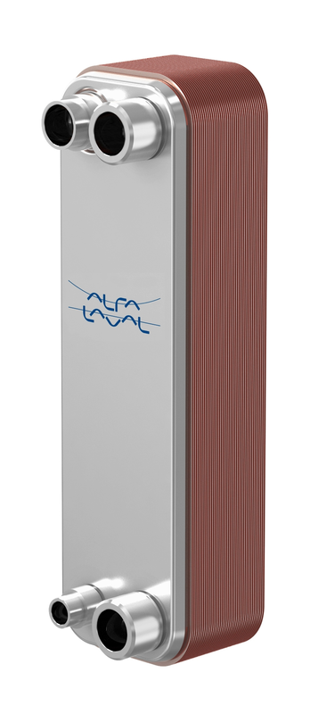
- Internal fouling caused by contaminated water, oil or process fluid, indicated by reduced heat-transfer capacity and increasing pressure drop
- Flow restriction caused by debris, deposits or blocked upstream strainers, indicated by low flow and abnormal operating pressures or temperatures
- External leakage at connections or brazed joints caused by corrosion, vibration or piping stress, indicated by visible fluid, oil traces or loss of refrigerant charge
- Internal cross-leakage caused by plate or brazed-joint failure, indicated by contamination between circuits or unexplained loss from one side
- Freeze damage in evaporator or chilled-fluid service caused by inadequate flow or control malfunction, indicated by sudden leakage or loss of pressure integrity
- Refrigerant maldistribution or unstable control caused by system-side faults, indicated by fluctuating superheat, capacity or discharge conditions
- Internal fouling caused by contaminated water, oil or process fluid, indicated by reduced heat-transfer capacity and increasing pressure drop
- Flow restriction caused by debris, deposits or blocked upstream strainers, indicated by low flow and abnormal operating pressures or temperatures
- External leakage at connections or brazed joints caused by corrosion, vibration or piping stress, indicated by visible fluid, oil traces or loss of refrigerant charge
- Internal cross-leakage caused by plate or brazed-joint failure, indicated by contamination between circuits or unexplained loss from one side
- Freeze damage in evaporator or chilled-fluid service caused by inadequate flow or control malfunction, indicated by sudden leakage or loss of pressure integrity
- Refrigerant maldistribution or unstable control caused by system-side faults, indicated by fluctuating superheat, capacity or discharge conditions
- Internal fouling caused by contaminated water, oil or process fluid, indicated by reduced heat-transfer capacity and increasing pressure drop
- Flow restriction caused by debris, deposits or blocked upstream strainers, indicated by low flow and abnormal operating pressures or temperatures
- External leakage at connections or brazed joints caused by corrosion, vibration or piping stress, indicated by visible fluid, oil traces or loss of refrigerant charge
- Internal cross-leakage caused by plate or brazed-joint failure, indicated by contamination between circuits or unexplained loss from one side
- Freeze damage in evaporator or chilled-fluid service caused by inadequate flow or control malfunction, indicated by sudden leakage or loss of pressure integrity
- Refrigerant maldistribution or unstable control caused by system-side faults, indicated by fluctuating superheat, capacity or discharge conditions
- Internal fouling caused by contaminated water, oil or process fluid, indicated by reduced heat-transfer capacity and increasing pressure drop
- Flow restriction caused by debris, deposits or blocked upstream strainers, indicated by low flow and abnormal operating pressures or temperatures
- External leakage at connections or brazed joints caused by corrosion, vibration or piping stress, indicated by visible fluid, oil traces or loss of refrigerant charge
- Internal cross-leakage caused by plate or brazed-joint failure, indicated by contamination between circuits or unexplained loss from one side
- Freeze damage in evaporator or chilled-fluid service caused by inadequate flow or control malfunction, indicated by sudden leakage or loss of pressure integrity
- Refrigerant maldistribution or unstable control caused by system-side faults, indicated by fluctuating superheat, capacity or discharge conditions
- Internal fouling caused by contaminated water, oil or process fluid, indicated by reduced heat-transfer capacity and increasing pressure drop
- Flow restriction caused by debris, deposits or blocked upstream strainers, indicated by low flow and abnormal operating pressures or temperatures
- External leakage at connections or brazed joints caused by corrosion, vibration or piping stress, indicated by visible fluid, oil traces or loss of refrigerant charge
- Internal cross-leakage caused by plate or brazed-joint failure, indicated by contamination between circuits or unexplained loss from one side
- Freeze damage in evaporator or chilled-fluid service caused by inadequate flow or control malfunction, indicated by sudden leakage or loss of pressure integrity
- Refrigerant maldistribution or unstable control caused by system-side faults, indicated by fluctuating superheat, capacity or discharge conditions
- Internal fouling caused by contaminated water, oil or process fluid, indicated by reduced heat-transfer capacity and increasing pressure drop
- Flow restriction caused by debris, deposits or blocked upstream strainers, indicated by low flow and abnormal operating pressures or temperatures
- External leakage at connections or brazed joints caused by corrosion, vibration or piping stress, indicated by visible fluid, oil traces or loss of refrigerant charge
- Internal cross-leakage caused by plate or brazed-joint failure, indicated by contamination between circuits or unexplained loss from one side
- Freeze damage in evaporator or chilled-fluid service caused by inadequate flow or control malfunction, indicated by sudden leakage or loss of pressure integrity
- Refrigerant maldistribution or unstable control caused by system-side faults, indicated by fluctuating superheat, capacity or discharge conditions
- Internal fouling caused by contaminated water, oil or process fluid, indicated by reduced heat-transfer capacity and increasing pressure drop
- Flow restriction caused by debris, deposits or blocked upstream strainers, indicated by low flow and abnormal operating pressures or temperatures
- External leakage at connections or brazed joints caused by corrosion, vibration or piping stress, indicated by visible fluid, oil traces or loss of refrigerant charge
- Internal cross-leakage caused by plate or brazed-joint failure, indicated by contamination between circuits or unexplained loss from one side
- Freeze damage in evaporator or chilled-fluid service caused by inadequate flow or control malfunction, indicated by sudden leakage or loss of pressure integrity
- Refrigerant maldistribution or unstable control caused by system-side faults, indicated by fluctuating superheat, capacity or discharge conditions
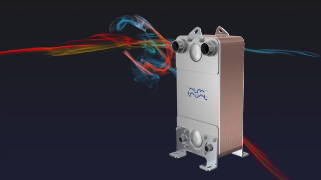
- Internal fouling caused by contaminated water, oil or process fluid, indicated by reduced heat-transfer capacity and increasing pressure drop
- Flow restriction caused by debris, deposits or blocked upstream strainers, indicated by low flow and abnormal operating pressures or temperatures
- External leakage at connections or brazed joints caused by corrosion, vibration or piping stress, indicated by visible fluid, oil traces or loss of refrigerant charge
- Internal cross-leakage caused by plate or brazed-joint failure, indicated by contamination between circuits or unexplained loss from one side
- Freeze damage in evaporator or chilled-fluid service caused by inadequate flow or control malfunction, indicated by sudden leakage or loss of pressure integrity
- Refrigerant maldistribution or unstable control caused by system-side faults, indicated by fluctuating superheat, capacity or discharge conditions
- Internal fouling caused by contaminated water, oil or process fluid, indicated by reduced heat-transfer capacity and increasing pressure drop
- Flow restriction caused by debris, deposits or blocked upstream strainers, indicated by low flow and abnormal operating pressures or temperatures
- External leakage at connections or brazed joints caused by corrosion, vibration or piping stress, indicated by visible fluid, oil traces or loss of refrigerant charge
- Internal cross-leakage caused by plate or brazed-joint failure, indicated by contamination between circuits or unexplained loss from one side
- Freeze damage in evaporator or chilled-fluid service caused by inadequate flow or control malfunction, indicated by sudden leakage or loss of pressure integrity
- Refrigerant maldistribution or unstable control caused by system-side faults, indicated by fluctuating superheat, capacity or discharge conditions
- Internal fouling caused by contaminated water, oil or process fluid, indicated by reduced heat-transfer capacity and increasing pressure drop
- Flow restriction caused by debris, deposits or blocked upstream strainers, indicated by low flow and abnormal operating pressures or temperatures
- External leakage at connections or brazed joints caused by corrosion, vibration or piping stress, indicated by visible fluid, oil traces or loss of refrigerant charge
- Internal cross-leakage caused by plate or brazed-joint failure, indicated by contamination between circuits or unexplained loss from one side
- Freeze damage in evaporator or chilled-fluid service caused by inadequate flow or control malfunction, indicated by sudden leakage or loss of pressure integrity
- Refrigerant maldistribution or unstable control caused by system-side faults, indicated by fluctuating superheat, capacity or discharge conditions
- Internal fouling caused by contaminated water, oil or process fluid, indicated by reduced heat-transfer capacity and increasing pressure drop
- Flow restriction caused by debris, deposits or blocked upstream strainers, indicated by low flow and abnormal operating pressures or temperatures
- External leakage at connections or brazed joints caused by corrosion, vibration or piping stress, indicated by visible fluid, oil traces or loss of refrigerant charge
- Internal cross-leakage caused by plate or brazed-joint failure, indicated by contamination between circuits or unexplained loss from one side
- Freeze damage in evaporator or chilled-fluid service caused by inadequate flow or control malfunction, indicated by sudden leakage or loss of pressure integrity
- Refrigerant maldistribution or unstable control caused by system-side faults, indicated by fluctuating superheat, capacity or discharge conditions
- Internal fouling caused by contaminated water, oil or process fluid, indicated by reduced heat-transfer capacity and increasing pressure drop
- Flow restriction caused by debris, deposits or blocked upstream strainers, indicated by low flow and abnormal operating pressures or temperatures
- External leakage at connections or brazed joints caused by corrosion, vibration or piping stress, indicated by visible fluid, oil traces or loss of refrigerant charge
- Internal cross-leakage caused by plate or brazed-joint failure, indicated by contamination between circuits or unexplained loss from one side
- Freeze damage in evaporator or chilled-fluid service caused by inadequate flow or control malfunction, indicated by sudden leakage or loss of pressure integrity
- Refrigerant maldistribution or unstable control caused by system-side faults, indicated by fluctuating superheat, capacity or discharge conditions
- Internal fouling caused by contaminated water, oil or process fluid, indicated by reduced heat-transfer capacity and increasing pressure drop
- Flow restriction caused by debris, deposits or blocked upstream strainers, indicated by low flow and abnormal operating pressures or temperatures
- External leakage at connections or brazed joints caused by corrosion, vibration or piping stress, indicated by visible fluid, oil traces or loss of refrigerant charge
- Internal cross-leakage caused by plate or brazed-joint failure, indicated by contamination between circuits or unexplained loss from one side
- Freeze damage in evaporator or chilled-fluid service caused by inadequate flow or control malfunction, indicated by sudden leakage or loss of pressure integrity
- Refrigerant maldistribution or unstable control caused by system-side faults, indicated by fluctuating superheat, capacity or discharge conditions
- Internal fouling caused by contaminated water, oil or process fluid, indicated by reduced heat-transfer capacity and increasing pressure drop
- Flow restriction caused by debris, deposits or blocked upstream strainers, indicated by low flow and abnormal operating pressures or temperatures
- External leakage at connections or brazed joints caused by corrosion, vibration or piping stress, indicated by visible fluid, oil traces or loss of refrigerant charge
- Internal cross-leakage caused by plate or brazed-joint failure, indicated by contamination between circuits or unexplained loss from one side
- Freeze damage in evaporator or chilled-fluid service caused by inadequate flow or control malfunction, indicated by sudden leakage or loss of pressure integrity
- Refrigerant maldistribution or unstable control caused by system-side faults, indicated by fluctuating superheat, capacity or discharge conditions
- Internal fouling caused by contaminated water, oil or process fluid, indicated by reduced heat-transfer capacity and increasing pressure drop
- Flow restriction caused by debris, deposits or blocked upstream strainers, indicated by low flow and abnormal operating pressures or temperatures
- External leakage at connections or brazed joints caused by corrosion, vibration or piping stress, indicated by visible fluid, oil traces or loss of refrigerant charge
- Internal cross-leakage caused by plate or brazed-joint failure, indicated by contamination between circuits or unexplained loss from one side
- Freeze damage in evaporator or chilled-fluid service caused by inadequate flow or control malfunction, indicated by sudden leakage or loss of pressure integrity
- Refrigerant maldistribution or unstable control caused by system-side faults, indicated by fluctuating superheat, capacity or discharge conditions
- Internal fouling caused by contaminated water, oil or process fluid, indicated by reduced heat-transfer capacity and increasing pressure drop
- Flow restriction caused by debris, deposits or blocked upstream strainers, indicated by low flow and abnormal operating pressures or temperatures
- External leakage at connections or brazed joints caused by corrosion, vibration or piping stress, indicated by visible fluid, oil traces or loss of refrigerant charge
- Internal cross-leakage caused by plate or brazed-joint failure, indicated by contamination between circuits or unexplained loss from one side
- Freeze damage in evaporator or chilled-fluid service caused by inadequate flow or control malfunction, indicated by sudden leakage or loss of pressure integrity
- Refrigerant maldistribution or unstable control caused by system-side faults, indicated by fluctuating superheat, capacity or discharge conditions
- Internal fouling caused by contaminated water, oil or process fluid, indicated by reduced heat-transfer capacity and increasing pressure drop
- Flow restriction caused by debris, deposits or blocked upstream strainers, indicated by low flow and abnormal operating pressures or temperatures
- External leakage at connections or brazed joints caused by corrosion, vibration or piping stress, indicated by visible fluid, oil traces or loss of refrigerant charge
- Internal cross-leakage caused by plate or brazed-joint failure, indicated by contamination between circuits or unexplained loss from one side
- Freeze damage in evaporator or chilled-fluid service caused by inadequate flow or control malfunction, indicated by sudden leakage or loss of pressure integrity
- Refrigerant maldistribution or unstable control caused by system-side faults, indicated by fluctuating superheat, capacity or discharge conditions
- Internal fouling caused by contaminated water, oil or process fluid, indicated by reduced heat-transfer capacity and increasing pressure drop
- Flow restriction caused by debris, deposits or blocked upstream strainers, indicated by low flow and abnormal operating pressures or temperatures
- External leakage at connections or brazed joints caused by corrosion, vibration or piping stress, indicated by visible fluid, oil traces or loss of refrigerant charge
- Internal cross-leakage caused by plate or brazed-joint failure, indicated by contamination between circuits or unexplained loss from one side
- Freeze damage in evaporator or chilled-fluid service caused by inadequate flow or control malfunction, indicated by sudden leakage or loss of pressure integrity
- Refrigerant maldistribution or unstable control caused by system-side faults, indicated by fluctuating superheat, capacity or discharge conditions
- Internal fouling caused by contaminated water, oil or process fluid, indicated by reduced heat-transfer capacity and increasing pressure drop
- Flow restriction caused by debris, deposits or blocked upstream strainers, indicated by low flow and abnormal operating pressures or temperatures
- External leakage at connections or brazed joints caused by corrosion, vibration or piping stress, indicated by visible fluid, oil traces or loss of refrigerant charge
- Internal cross-leakage caused by plate or brazed-joint failure, indicated by contamination between circuits or unexplained loss from one side
- Freeze damage in evaporator or chilled-fluid service caused by inadequate flow or control malfunction, indicated by sudden leakage or loss of pressure integrity
- Refrigerant maldistribution or unstable control caused by system-side faults, indicated by fluctuating superheat, capacity or discharge conditions

- Internal fouling caused by contaminated water, oil or process fluid, indicated by reduced heat-transfer capacity and increasing pressure drop
- Flow restriction caused by debris, deposits or blocked upstream strainers, indicated by low flow and abnormal operating pressures or temperatures
- External leakage at connections or brazed joints caused by corrosion, vibration or piping stress, indicated by visible fluid, oil traces or loss of refrigerant charge
- Internal cross-leakage caused by plate or brazed-joint failure, indicated by contamination between circuits or unexplained loss from one side
- Freeze damage in evaporator or chilled-fluid service caused by inadequate flow or control malfunction, indicated by sudden leakage or loss of pressure integrity
- Refrigerant maldistribution or unstable control caused by system-side faults, indicated by fluctuating superheat, capacity or discharge conditions
- Internal fouling caused by contaminated water, oil or process fluid, indicated by reduced heat-transfer capacity and increasing pressure drop
- Flow restriction caused by debris, deposits or blocked upstream strainers, indicated by low flow and abnormal operating pressures or temperatures
- External leakage at connections or brazed joints caused by corrosion, vibration or piping stress, indicated by visible fluid, oil traces or loss of refrigerant charge
- Internal cross-leakage caused by plate or brazed-joint failure, indicated by contamination between circuits or unexplained loss from one side
- Freeze damage in evaporator or chilled-fluid service caused by inadequate flow or control malfunction, indicated by sudden leakage or loss of pressure integrity
- Refrigerant maldistribution or unstable control caused by system-side faults, indicated by fluctuating superheat, capacity or discharge conditions
- Internal fouling caused by contaminated water, oil or process fluid, indicated by reduced heat-transfer capacity and increasing pressure drop
- Flow restriction caused by debris, deposits or blocked upstream strainers, indicated by low flow and abnormal operating pressures or temperatures
- External leakage at connections or brazed joints caused by corrosion, vibration or piping stress, indicated by visible fluid, oil traces or loss of refrigerant charge
- Internal cross-leakage caused by plate or brazed-joint failure, indicated by contamination between circuits or unexplained loss from one side
- Freeze damage in evaporator or chilled-fluid service caused by inadequate flow or control malfunction, indicated by sudden leakage or loss of pressure integrity
- Refrigerant maldistribution or unstable control caused by system-side faults, indicated by fluctuating superheat, capacity or discharge conditions
- Internal fouling caused by contaminated water, oil or process fluid, indicated by reduced heat-transfer capacity and increasing pressure drop
- Flow restriction caused by debris, deposits or blocked upstream strainers, indicated by low flow and abnormal operating pressures or temperatures
- External leakage at connections or brazed joints caused by corrosion, vibration or piping stress, indicated by visible fluid, oil traces or loss of refrigerant charge
- Internal cross-leakage caused by plate or brazed-joint failure, indicated by contamination between circuits or unexplained loss from one side
- Freeze damage in evaporator or chilled-fluid service caused by inadequate flow or control malfunction, indicated by sudden leakage or loss of pressure integrity
- Refrigerant maldistribution or unstable control caused by system-side faults, indicated by fluctuating superheat, capacity or discharge conditions
- Internal fouling caused by contaminated water, oil or process fluid, indicated by reduced heat-transfer capacity and increasing pressure drop
- Flow restriction caused by debris, deposits or blocked upstream strainers, indicated by low flow and abnormal operating pressures or temperatures
- External leakage at connections or brazed joints caused by corrosion, vibration or piping stress, indicated by visible fluid, oil traces or loss of refrigerant charge
- Internal cross-leakage caused by plate or brazed-joint failure, indicated by contamination between circuits or unexplained loss from one side
- Freeze damage in evaporator or chilled-fluid service caused by inadequate flow or control malfunction, indicated by sudden leakage or loss of pressure integrity
- Refrigerant maldistribution or unstable control caused by system-side faults, indicated by fluctuating superheat, capacity or discharge conditions
- Internal fouling caused by contaminated water, oil or process fluid, indicated by reduced heat-transfer capacity and increasing pressure drop
- Flow restriction caused by debris, deposits or blocked upstream strainers, indicated by low flow and abnormal operating pressures or temperatures
- External leakage at connections or brazed joints caused by corrosion, vibration or piping stress, indicated by visible fluid, oil traces or loss of refrigerant charge
- Internal cross-leakage caused by plate or brazed-joint failure, indicated by contamination between circuits or unexplained loss from one side
- Freeze damage in evaporator or chilled-fluid service caused by inadequate flow or control malfunction, indicated by sudden leakage or loss of pressure integrity
- Refrigerant maldistribution or unstable control caused by system-side faults, indicated by fluctuating superheat, capacity or discharge conditions
- Internal fouling caused by contaminated water, oil or process fluid, indicated by reduced heat-transfer capacity and increasing pressure drop
- Flow restriction caused by debris, deposits or blocked upstream strainers, indicated by low flow and abnormal operating pressures or temperatures
- External leakage at connections or brazed joints caused by corrosion, vibration or piping stress, indicated by visible fluid, oil traces or loss of refrigerant charge
- Internal cross-leakage caused by plate or brazed-joint failure, indicated by contamination between circuits or unexplained loss from one side
- Freeze damage in evaporator or chilled-fluid service caused by inadequate flow or control malfunction, indicated by sudden leakage or loss of pressure integrity
- Refrigerant maldistribution or unstable control caused by system-side faults, indicated by fluctuating superheat, capacity or discharge conditions
- Internal fouling caused by contaminated water, oil or process fluid, indicated by reduced heat-transfer capacity and increasing pressure drop
- Flow restriction caused by debris, deposits or blocked upstream strainers, indicated by low flow and abnormal operating pressures or temperatures
- External leakage at connections or brazed joints caused by corrosion, vibration or piping stress, indicated by visible fluid, oil traces or loss of refrigerant charge
- Internal cross-leakage caused by plate or brazed-joint failure, indicated by contamination between circuits or unexplained loss from one side
- Freeze damage in evaporator or chilled-fluid service caused by inadequate flow or control malfunction, indicated by sudden leakage or loss of pressure integrity
- Refrigerant maldistribution or unstable control caused by system-side faults, indicated by fluctuating superheat, capacity or discharge conditions
- Internal fouling caused by contaminated water, oil or process fluid, indicated by reduced heat-transfer capacity and increasing pressure drop
- Flow restriction caused by debris, deposits or blocked upstream strainers, indicated by low flow and abnormal operating pressures or temperatures
- External leakage at connections or brazed joints caused by corrosion, vibration or piping stress, indicated by visible fluid, oil traces or loss of refrigerant charge
- Internal cross-leakage caused by plate or brazed-joint failure, indicated by contamination between circuits or unexplained loss from one side
- Freeze damage in evaporator or chilled-fluid service caused by inadequate flow or control malfunction, indicated by sudden leakage or loss of pressure integrity
- Refrigerant maldistribution or unstable control caused by system-side faults, indicated by fluctuating superheat, capacity or discharge conditions
- Internal fouling caused by contaminated water, oil or process fluid, indicated by reduced heat-transfer capacity and increasing pressure drop
- Flow restriction caused by debris, deposits or blocked upstream strainers, indicated by low flow and abnormal operating pressures or temperatures
- External leakage at connections or brazed joints caused by corrosion, vibration or piping stress, indicated by visible fluid, oil traces or loss of refrigerant charge
- Internal cross-leakage caused by plate or brazed-joint failure, indicated by contamination between circuits or unexplained loss from one side
- Freeze damage in evaporator or chilled-fluid service caused by inadequate flow or control malfunction, indicated by sudden leakage or loss of pressure integrity
- Refrigerant maldistribution or unstable control caused by system-side faults, indicated by fluctuating superheat, capacity or discharge conditions
- Internal fouling caused by contaminated water, oil or process fluid, indicated by reduced heat-transfer capacity and increasing pressure drop
- Flow restriction caused by debris, deposits or blocked upstream strainers, indicated by low flow and abnormal operating pressures or temperatures
- External leakage at connections or brazed joints caused by corrosion, vibration or piping stress, indicated by visible fluid, oil traces or loss of refrigerant charge
- Internal cross-leakage caused by plate or brazed-joint failure, indicated by contamination between circuits or unexplained loss from one side
- Freeze damage in evaporator or chilled-fluid service caused by inadequate flow or control malfunction, indicated by sudden leakage or loss of pressure integrity
- Refrigerant maldistribution or unstable control caused by system-side faults, indicated by fluctuating superheat, capacity or discharge conditions
- Internal fouling caused by contaminated water, oil or process fluid, indicated by reduced heat-transfer capacity and increasing pressure drop
- Flow restriction caused by debris, deposits or blocked upstream strainers, indicated by low flow and abnormal operating pressures or temperatures
- External leakage at connections or brazed joints caused by corrosion, vibration or piping stress, indicated by visible fluid, oil traces or loss of refrigerant charge
- Internal cross-leakage caused by plate or brazed-joint failure, indicated by contamination between circuits or unexplained loss from one side
- Freeze damage in evaporator or chilled-fluid service caused by inadequate flow or control malfunction, indicated by sudden leakage or loss of pressure integrity
- Refrigerant maldistribution or unstable control caused by system-side faults, indicated by fluctuating superheat, capacity or discharge conditions
- Internal fouling caused by contaminated water, oil or process fluid, indicated by reduced heat-transfer capacity and increasing pressure drop
- Flow restriction caused by debris, deposits or blocked upstream strainers, indicated by low flow and abnormal operating pressures or temperatures
- External leakage at connections or brazed joints caused by corrosion, vibration or piping stress, indicated by visible fluid, oil traces or loss of refrigerant charge
- Internal cross-leakage caused by plate or brazed-joint failure, indicated by contamination between circuits or unexplained loss from one side
- Freeze damage in evaporator or chilled-fluid service caused by inadequate flow or control malfunction, indicated by sudden leakage or loss of pressure integrity
- Refrigerant maldistribution or unstable control caused by system-side faults, indicated by fluctuating superheat, capacity or discharge conditions
- Internal fouling caused by contaminated water, oil or process fluid, indicated by reduced heat-transfer capacity and increasing pressure drop
- Flow restriction caused by debris, deposits or blocked upstream strainers, indicated by low flow and abnormal operating pressures or temperatures
- External leakage at connections or brazed joints caused by corrosion, vibration or piping stress, indicated by visible fluid, oil traces or loss of refrigerant charge
- Internal cross-leakage caused by plate or brazed-joint failure, indicated by contamination between circuits or unexplained loss from one side
- Freeze damage in evaporator or chilled-fluid service caused by inadequate flow or control malfunction, indicated by sudden leakage or loss of pressure integrity
- Refrigerant maldistribution or unstable control caused by system-side faults, indicated by fluctuating superheat, capacity or discharge conditions
- Internal fouling caused by contaminated water, oil or process fluid, indicated by reduced heat-transfer capacity and increasing pressure drop
- Flow restriction caused by debris, deposits or blocked upstream strainers, indicated by low flow and abnormal operating pressures or temperatures
- External leakage at connections or brazed joints caused by corrosion, vibration or piping stress, indicated by visible fluid, oil traces or loss of refrigerant charge
- Internal cross-leakage caused by plate or brazed-joint failure, indicated by contamination between circuits or unexplained loss from one side
- Freeze damage in evaporator or chilled-fluid service caused by inadequate flow or control malfunction, indicated by sudden leakage or loss of pressure integrity
- Refrigerant maldistribution or unstable control caused by system-side faults, indicated by fluctuating superheat, capacity or discharge conditions
- Internal fouling caused by contaminated water, oil or process fluid, indicated by reduced heat-transfer capacity and increasing pressure drop
- Flow restriction caused by debris, deposits or blocked upstream strainers, indicated by low flow and abnormal operating pressures or temperatures
- External leakage at connections or brazed joints caused by corrosion, vibration or piping stress, indicated by visible fluid, oil traces or loss of refrigerant charge
- Internal cross-leakage caused by plate or brazed-joint failure, indicated by contamination between circuits or unexplained loss from one side
- Freeze damage in evaporator or chilled-fluid service caused by inadequate flow or control malfunction, indicated by sudden leakage or loss of pressure integrity
- Refrigerant maldistribution or unstable control caused by system-side faults, indicated by fluctuating superheat, capacity or discharge conditions
- Internal fouling caused by contaminated water, oil or process fluid, indicated by reduced heat-transfer capacity and increasing pressure drop
- Flow restriction caused by debris, deposits or blocked upstream strainers, indicated by low flow and abnormal operating pressures or temperatures
- External leakage at connections or brazed joints caused by corrosion, vibration or piping stress, indicated by visible fluid, oil traces or loss of refrigerant charge
- Internal cross-leakage caused by plate or brazed-joint failure, indicated by contamination between circuits or unexplained loss from one side
- Freeze damage in evaporator or chilled-fluid service caused by inadequate flow or control malfunction, indicated by sudden leakage or loss of pressure integrity
- Refrigerant maldistribution or unstable control caused by system-side faults, indicated by fluctuating superheat, capacity or discharge conditions
- Internal fouling caused by contaminated water, oil or process fluid, indicated by reduced heat-transfer capacity and increasing pressure drop
- Flow restriction caused by debris, deposits or blocked upstream strainers, indicated by low flow and abnormal operating pressures or temperatures
- External leakage at connections or brazed joints caused by corrosion, vibration or piping stress, indicated by visible fluid, oil traces or loss of refrigerant charge
- Internal cross-leakage caused by plate or brazed-joint failure, indicated by contamination between circuits or unexplained loss from one side
- Freeze damage in evaporator or chilled-fluid service caused by inadequate flow or control malfunction, indicated by sudden leakage or loss of pressure integrity
- Refrigerant maldistribution or unstable control caused by system-side faults, indicated by fluctuating superheat, capacity or discharge conditions
- Internal fouling caused by contaminated water, oil or process fluid, indicated by reduced heat-transfer capacity and increasing pressure drop
- Flow restriction caused by debris, deposits or blocked upstream strainers, indicated by low flow and abnormal operating pressures or temperatures
- External leakage at connections or brazed joints caused by corrosion, vibration or piping stress, indicated by visible fluid, oil traces or loss of refrigerant charge
- Internal cross-leakage caused by plate or brazed-joint failure, indicated by contamination between circuits or unexplained loss from one side
- Freeze damage in evaporator or chilled-fluid service caused by inadequate flow or control malfunction, indicated by sudden leakage or loss of pressure integrity
- Refrigerant maldistribution or unstable control caused by system-side faults, indicated by fluctuating superheat, capacity or discharge conditions
- Internal fouling caused by contaminated water, oil or process fluid, indicated by reduced heat-transfer capacity and increasing pressure drop
- Flow restriction caused by debris, deposits or blocked upstream strainers, indicated by low flow and abnormal operating pressures or temperatures
- External leakage at connections or brazed joints caused by corrosion, vibration or piping stress, indicated by visible fluid, oil traces or loss of refrigerant charge
- Internal cross-leakage caused by plate or brazed-joint failure, indicated by contamination between circuits or unexplained loss from one side
- Freeze damage in evaporator or chilled-fluid service caused by inadequate flow or control malfunction, indicated by sudden leakage or loss of pressure integrity
- Refrigerant maldistribution or unstable control caused by system-side faults, indicated by fluctuating superheat, capacity or discharge conditions
- Internal fouling caused by contaminated water, oil or process fluid, indicated by reduced heat-transfer capacity and increasing pressure drop
- Flow restriction caused by debris, deposits or blocked upstream strainers, indicated by low flow and abnormal operating pressures or temperatures
- External leakage at connections or brazed joints caused by corrosion, vibration or piping stress, indicated by visible fluid, oil traces or loss of refrigerant charge
- Internal cross-leakage caused by plate or brazed-joint failure, indicated by contamination between circuits or unexplained loss from one side
- Freeze damage in evaporator or chilled-fluid service caused by inadequate flow or control malfunction, indicated by sudden leakage or loss of pressure integrity
- Refrigerant maldistribution or unstable control caused by system-side faults, indicated by fluctuating superheat, capacity or discharge conditions
- Internal fouling caused by contaminated water, oil or process fluid, indicated by reduced heat-transfer capacity and increasing pressure drop
- Flow restriction caused by debris, deposits or blocked upstream strainers, indicated by low flow and abnormal operating pressures or temperatures
- External leakage at connections or brazed joints caused by corrosion, vibration or piping stress, indicated by visible fluid, oil traces or loss of refrigerant charge
- Internal cross-leakage caused by plate or brazed-joint failure, indicated by contamination between circuits or unexplained loss from one side
- Freeze damage in evaporator or chilled-fluid service caused by inadequate flow or control malfunction, indicated by sudden leakage or loss of pressure integrity
- Refrigerant maldistribution or unstable control caused by system-side faults, indicated by fluctuating superheat, capacity or discharge conditions
- Internal fouling caused by contaminated water, oil or process fluid, indicated by reduced heat-transfer capacity and increasing pressure drop
- Flow restriction caused by debris, deposits or blocked upstream strainers, indicated by low flow and abnormal operating pressures or temperatures
- External leakage at connections or brazed joints caused by corrosion, vibration or piping stress, indicated by visible fluid, oil traces or loss of refrigerant charge
- Internal cross-leakage caused by plate or brazed-joint failure, indicated by contamination between circuits or unexplained loss from one side
- Freeze damage in evaporator or chilled-fluid service caused by inadequate flow or control malfunction, indicated by sudden leakage or loss of pressure integrity
- Refrigerant maldistribution or unstable control caused by system-side faults, indicated by fluctuating superheat, capacity or discharge conditions
- Internal fouling caused by contaminated water, oil or process fluid, indicated by reduced heat-transfer capacity and increasing pressure drop
- Flow restriction caused by debris, deposits or blocked upstream strainers, indicated by low flow and abnormal operating pressures or temperatures
- External leakage at connections or brazed joints caused by corrosion, vibration or piping stress, indicated by visible fluid, oil traces or loss of refrigerant charge
- Internal cross-leakage caused by plate or brazed-joint failure, indicated by contamination between circuits or unexplained loss from one side
- Freeze damage in evaporator or chilled-fluid service caused by inadequate flow or control malfunction, indicated by sudden leakage or loss of pressure integrity
- Refrigerant maldistribution or unstable control caused by system-side faults, indicated by fluctuating superheat, capacity or discharge conditions
- Internal fouling caused by contaminated water, oil or process fluid, indicated by reduced heat-transfer capacity and increasing pressure drop
- Flow restriction caused by debris, deposits or blocked upstream strainers, indicated by low flow and abnormal operating pressures or temperatures
- External leakage at connections or brazed joints caused by corrosion, vibration or piping stress, indicated by visible fluid, oil traces or loss of refrigerant charge
- Internal cross-leakage caused by plate or brazed-joint failure, indicated by contamination between circuits or unexplained loss from one side
- Freeze damage in evaporator or chilled-fluid service caused by inadequate flow or control malfunction, indicated by sudden leakage or loss of pressure integrity
- Refrigerant maldistribution or unstable control caused by system-side faults, indicated by fluctuating superheat, capacity or discharge conditions
- Internal fouling caused by contaminated water, oil or process fluid, indicated by reduced heat-transfer capacity and increasing pressure drop
- Flow restriction caused by debris, deposits or blocked upstream strainers, indicated by low flow and abnormal operating pressures or temperatures
- External leakage at connections or brazed joints caused by corrosion, vibration or piping stress, indicated by visible fluid, oil traces or loss of refrigerant charge
- Internal cross-leakage caused by plate or brazed-joint failure, indicated by contamination between circuits or unexplained loss from one side
- Freeze damage in evaporator or chilled-fluid service caused by inadequate flow or control malfunction, indicated by sudden leakage or loss of pressure integrity
- Refrigerant maldistribution or unstable control caused by system-side faults, indicated by fluctuating superheat, capacity or discharge conditions
- Internal fouling caused by contaminated water, oil or process fluid, indicated by reduced heat-transfer capacity and increasing pressure drop
- Flow restriction caused by debris, deposits or blocked upstream strainers, indicated by low flow and abnormal operating pressures or temperatures
- External leakage at connections or brazed joints caused by corrosion, vibration or piping stress, indicated by visible fluid, oil traces or loss of refrigerant charge
- Internal cross-leakage caused by plate or brazed-joint failure, indicated by contamination between circuits or unexplained loss from one side
- Freeze damage in evaporator or chilled-fluid service caused by inadequate flow or control malfunction, indicated by sudden leakage or loss of pressure integrity
- Refrigerant maldistribution or unstable control caused by system-side faults, indicated by fluctuating superheat, capacity or discharge conditions
- Internal fouling caused by contaminated water, oil or process fluid, indicated by reduced heat-transfer capacity and increasing pressure drop
- Flow restriction caused by debris, deposits or blocked upstream strainers, indicated by low flow and abnormal operating pressures or temperatures
- External leakage at connections or brazed joints caused by corrosion, vibration or piping stress, indicated by visible fluid, oil traces or loss of refrigerant charge
- Internal cross-leakage caused by plate or brazed-joint failure, indicated by contamination between circuits or unexplained loss from one side
- Freeze damage in evaporator or chilled-fluid service caused by inadequate flow or control malfunction, indicated by sudden leakage or loss of pressure integrity
- Refrigerant maldistribution or unstable control caused by system-side faults, indicated by fluctuating superheat, capacity or discharge conditions
- Internal fouling caused by contaminated water, oil or process fluid, indicated by reduced heat-transfer capacity and increasing pressure drop
- Flow restriction caused by debris, deposits or blocked upstream strainers, indicated by low flow and abnormal operating pressures or temperatures
- External leakage at connections or brazed joints caused by corrosion, vibration or piping stress, indicated by visible fluid, oil traces or loss of refrigerant charge
- Internal cross-leakage caused by plate or brazed-joint failure, indicated by contamination between circuits or unexplained loss from one side
- Freeze damage in evaporator or chilled-fluid service caused by inadequate flow or control malfunction, indicated by sudden leakage or loss of pressure integrity
- Refrigerant maldistribution or unstable control caused by system-side faults, indicated by fluctuating superheat, capacity or discharge conditions
- Internal fouling caused by contaminated water, oil or process fluid, indicated by reduced heat-transfer capacity and increasing pressure drop
- Flow restriction caused by debris, deposits or blocked upstream strainers, indicated by low flow and abnormal operating pressures or temperatures
- External leakage at connections or brazed joints caused by corrosion, vibration or piping stress, indicated by visible fluid, oil traces or loss of refrigerant charge
- Internal cross-leakage caused by plate or brazed-joint failure, indicated by contamination between circuits or unexplained loss from one side
- Freeze damage in evaporator or chilled-fluid service caused by inadequate flow or control malfunction, indicated by sudden leakage or loss of pressure integrity
- Refrigerant maldistribution or unstable control caused by system-side faults, indicated by fluctuating superheat, capacity or discharge conditions
- Internal fouling caused by contaminated water, oil or process fluid, indicated by reduced heat-transfer capacity and increasing pressure drop
- Flow restriction caused by debris, deposits or blocked upstream strainers, indicated by low flow and abnormal operating pressures or temperatures
- External leakage at connections or brazed joints caused by corrosion, vibration or piping stress, indicated by visible fluid, oil traces or loss of refrigerant charge
- Internal cross-leakage caused by plate or brazed-joint failure, indicated by contamination between circuits or unexplained loss from one side
- Freeze damage in evaporator or chilled-fluid service caused by inadequate flow or control malfunction, indicated by sudden leakage or loss of pressure integrity
- Refrigerant maldistribution or unstable control caused by system-side faults, indicated by fluctuating superheat, capacity or discharge conditions
- Internal fouling caused by contaminated water, oil or process fluid, indicated by reduced heat-transfer capacity and increasing pressure drop
- Flow restriction caused by debris, deposits or blocked upstream strainers, indicated by low flow and abnormal operating pressures or temperatures
- External leakage at connections or brazed joints caused by corrosion, vibration or piping stress, indicated by visible fluid, oil traces or loss of refrigerant charge
- Internal cross-leakage caused by plate or brazed-joint failure, indicated by contamination between circuits or unexplained loss from one side
- Freeze damage in evaporator or chilled-fluid service caused by inadequate flow or control malfunction, indicated by sudden leakage or loss of pressure integrity
- Refrigerant maldistribution or unstable control caused by system-side faults, indicated by fluctuating superheat, capacity or discharge conditions
- Internal fouling caused by contaminated water, oil or process fluid, indicated by reduced heat-transfer capacity and increasing pressure drop
- Flow restriction caused by debris, deposits or blocked upstream strainers, indicated by low flow and abnormal operating pressures or temperatures
- External leakage at connections or brazed joints caused by corrosion, vibration or piping stress, indicated by visible fluid, oil traces or loss of refrigerant charge
- Internal cross-leakage caused by plate or brazed-joint failure, indicated by contamination between circuits or unexplained loss from one side
- Freeze damage in evaporator or chilled-fluid service caused by inadequate flow or control malfunction, indicated by sudden leakage or loss of pressure integrity
- Refrigerant maldistribution or unstable control caused by system-side faults, indicated by fluctuating superheat, capacity or discharge conditions
- Internal fouling caused by contaminated water, oil or process fluid, indicated by reduced heat-transfer capacity and increasing pressure drop
- Flow restriction caused by debris, deposits or blocked upstream strainers, indicated by low flow and abnormal operating pressures or temperatures
- External leakage at connections or brazed joints caused by corrosion, vibration or piping stress, indicated by visible fluid, oil traces or loss of refrigerant charge
- Internal cross-leakage caused by plate or brazed-joint failure, indicated by contamination between circuits or unexplained loss from one side
- Freeze damage in evaporator or chilled-fluid service caused by inadequate flow or control malfunction, indicated by sudden leakage or loss of pressure integrity
- Refrigerant maldistribution or unstable control caused by system-side faults, indicated by fluctuating superheat, capacity or discharge conditions
- Internal fouling caused by contaminated water, oil or process fluid, indicated by reduced heat-transfer capacity and increasing pressure drop
- Flow restriction caused by debris, deposits or blocked upstream strainers, indicated by low flow and abnormal operating pressures or temperatures
- External leakage at connections or brazed joints caused by corrosion, vibration or piping stress, indicated by visible fluid, oil traces or loss of refrigerant charge
- Internal cross-leakage caused by plate or brazed-joint failure, indicated by contamination between circuits or unexplained loss from one side
- Freeze damage in evaporator or chilled-fluid service caused by inadequate flow or control malfunction, indicated by sudden leakage or loss of pressure integrity
- Refrigerant maldistribution or unstable control caused by system-side faults, indicated by fluctuating superheat, capacity or discharge conditions
- Internal fouling caused by contaminated water, oil or process fluid, indicated by reduced heat-transfer capacity and increasing pressure drop
- Flow restriction caused by debris, deposits or blocked upstream strainers, indicated by low flow and abnormal operating pressures or temperatures
- External leakage at connections or brazed joints caused by corrosion, vibration or piping stress, indicated by visible fluid, oil traces or loss of refrigerant charge
- Internal cross-leakage caused by plate or brazed-joint failure, indicated by contamination between circuits or unexplained loss from one side
- Freeze damage in evaporator or chilled-fluid service caused by inadequate flow or control malfunction, indicated by sudden leakage or loss of pressure integrity
- Refrigerant maldistribution or unstable control caused by system-side faults, indicated by fluctuating superheat, capacity or discharge conditions
- Internal fouling caused by contaminated water, oil or process fluid, indicated by reduced heat-transfer capacity and increasing pressure drop
- Flow restriction caused by debris, deposits or blocked upstream strainers, indicated by low flow and abnormal operating pressures or temperatures
- External leakage at connections or brazed joints caused by corrosion, vibration or piping stress, indicated by visible fluid, oil traces or loss of refrigerant charge
- Internal cross-leakage caused by plate or brazed-joint failure, indicated by contamination between circuits or unexplained loss from one side
- Freeze damage in evaporator or chilled-fluid service caused by inadequate flow or control malfunction, indicated by sudden leakage or loss of pressure integrity
- Refrigerant maldistribution or unstable control caused by system-side faults, indicated by fluctuating superheat, capacity or discharge conditions
- Internal fouling caused by contaminated water, oil or process fluid, indicated by reduced heat-transfer capacity and increasing pressure drop
- Flow restriction caused by debris, deposits or blocked upstream strainers, indicated by low flow and abnormal operating pressures or temperatures
- External leakage at connections or brazed joints caused by corrosion, vibration or piping stress, indicated by visible fluid, oil traces or loss of refrigerant charge
- Internal cross-leakage caused by plate or brazed-joint failure, indicated by contamination between circuits or unexplained loss from one side
- Freeze damage in evaporator or chilled-fluid service caused by inadequate flow or control malfunction, indicated by sudden leakage or loss of pressure integrity
- Refrigerant maldistribution or unstable control caused by system-side faults, indicated by fluctuating superheat, capacity or discharge conditions
- Internal fouling caused by contaminated water, oil or process fluid, indicated by reduced heat-transfer capacity and increasing pressure drop
- Flow restriction caused by debris, deposits or blocked upstream strainers, indicated by low flow and abnormal operating pressures or temperatures
- External leakage at connections or brazed joints caused by corrosion, vibration or piping stress, indicated by visible fluid, oil traces or loss of refrigerant charge
- Internal cross-leakage caused by plate or brazed-joint failure, indicated by contamination between circuits or unexplained loss from one side
- Freeze damage in evaporator or chilled-fluid service caused by inadequate flow or control malfunction, indicated by sudden leakage or loss of pressure integrity
- Refrigerant maldistribution or unstable control caused by system-side faults, indicated by fluctuating superheat, capacity or discharge conditions
- Fouling of the narrow flow channels caused by scale, sludge, oil degradation products or dirty fluid, indicated by reduced heat transfer and increased pressure drop
- Partial blockage caused by debris or failed upstream filtration, indicated by reduced flow and abnormal temperature difference
- External leakage at brazed joints or connections caused by corrosion, fatigue or piping loads, indicated by visible leakage or fluid loss
- Internal plate failure or cross-leakage caused by corrosion, erosion or fatigue, indicated by contamination between circuits
- Freeze damage in susceptible cooling duties caused by inadequate flow or control failure, indicated by distortion, leakage or sudden loss of pressure integrity

- Fouling of the narrow flow channels caused by scale, sludge, oil degradation products or dirty fluid, indicated by reduced heat transfer and increased pressure drop
- Partial blockage caused by debris or failed upstream filtration, indicated by reduced flow and abnormal temperature difference
- External leakage at brazed joints or connections caused by corrosion, fatigue or piping loads, indicated by visible leakage or fluid loss
- Internal plate failure or cross-leakage caused by corrosion, erosion or fatigue, indicated by contamination between circuits
- Freeze damage in susceptible cooling duties caused by inadequate flow or control failure, indicated by distortion, leakage or sudden loss of pressure integrity
- Fouling of the narrow flow channels caused by scale, sludge, oil degradation products or dirty fluid, indicated by reduced heat transfer and increased pressure drop
- Partial blockage caused by debris or failed upstream filtration, indicated by reduced flow and abnormal temperature difference
- External leakage at brazed joints or connections caused by corrosion, fatigue or piping loads, indicated by visible leakage or fluid loss
- Internal plate failure or cross-leakage caused by corrosion, erosion or fatigue, indicated by contamination between circuits
- Freeze damage in susceptible cooling duties caused by inadequate flow or control failure, indicated by distortion, leakage or sudden loss of pressure integrity
- Fouling of the narrow flow channels caused by scale, sludge, oil degradation products or dirty fluid, indicated by reduced heat transfer and increased pressure drop
- Partial blockage caused by debris or failed upstream filtration, indicated by reduced flow and abnormal temperature difference
- External leakage at brazed joints or connections caused by corrosion, fatigue or piping loads, indicated by visible leakage or fluid loss
- Internal plate failure or cross-leakage caused by corrosion, erosion or fatigue, indicated by contamination between circuits
- Freeze damage in susceptible cooling duties caused by inadequate flow or control failure, indicated by distortion, leakage or sudden loss of pressure integrity
- Fouling of the narrow flow channels caused by scale, sludge, oil degradation products or dirty fluid, indicated by reduced heat transfer and increased pressure drop
- Partial blockage caused by debris or failed upstream filtration, indicated by reduced flow and abnormal temperature difference
- External leakage at brazed joints or connections caused by corrosion, fatigue or piping loads, indicated by visible leakage or fluid loss
- Internal plate failure or cross-leakage caused by corrosion, erosion or fatigue, indicated by contamination between circuits
- Freeze damage in susceptible cooling duties caused by inadequate flow or control failure, indicated by distortion, leakage or sudden loss of pressure integrity
- Fouling of the narrow flow channels caused by scale, sludge, oil degradation products or dirty fluid, indicated by reduced heat transfer and increased pressure drop
- Partial blockage caused by debris or failed upstream filtration, indicated by reduced flow and abnormal temperature difference
- External leakage at brazed joints or connections caused by corrosion, fatigue or piping loads, indicated by visible leakage or fluid loss
- Internal plate failure or cross-leakage caused by corrosion, erosion or fatigue, indicated by contamination between circuits
- Freeze damage in susceptible cooling duties caused by inadequate flow or control failure, indicated by distortion, leakage or sudden loss of pressure integrity
- Fouling of the narrow flow channels caused by scale, sludge, oil degradation products or dirty fluid, indicated by reduced heat transfer and increased pressure drop
- Partial blockage caused by debris or failed upstream filtration, indicated by reduced flow and abnormal temperature difference
- External leakage at brazed joints or connections caused by corrosion, fatigue or piping loads, indicated by visible leakage or fluid loss
- Internal plate failure or cross-leakage caused by corrosion, erosion or fatigue, indicated by contamination between circuits
- Freeze damage in susceptible cooling duties caused by inadequate flow or control failure, indicated by distortion, leakage or sudden loss of pressure integrity
- Fouling of the narrow flow channels caused by scale, sludge, oil degradation products or dirty fluid, indicated by reduced heat transfer and increased pressure drop
- Partial blockage caused by debris or failed upstream filtration, indicated by reduced flow and abnormal temperature difference
- External leakage at brazed joints or connections caused by corrosion, fatigue or piping loads, indicated by visible leakage or fluid loss
- Internal plate failure or cross-leakage caused by corrosion, erosion or fatigue, indicated by contamination between circuits
- Freeze damage in susceptible cooling duties caused by inadequate flow or control failure, indicated by distortion, leakage or sudden loss of pressure integrity
- Fouling of the narrow flow channels caused by scale, sludge, oil degradation products or dirty fluid, indicated by reduced heat transfer and increased pressure drop
- Partial blockage caused by debris or failed upstream filtration, indicated by reduced flow and abnormal temperature difference
- External leakage at brazed joints or connections caused by corrosion, fatigue or piping loads, indicated by visible leakage or fluid loss
- Internal plate failure or cross-leakage caused by corrosion, erosion or fatigue, indicated by contamination between circuits
- Freeze damage in susceptible cooling duties caused by inadequate flow or control failure, indicated by distortion, leakage or sudden loss of pressure integrity
- Fouling of the narrow flow channels caused by scale, sludge, oil degradation products or dirty fluid, indicated by reduced heat transfer and increased pressure drop
- Partial blockage caused by debris or failed upstream filtration, indicated by reduced flow and abnormal temperature difference
- External leakage at brazed joints or connections caused by corrosion, fatigue or piping loads, indicated by visible leakage or fluid loss
- Internal plate failure or cross-leakage caused by corrosion, erosion or fatigue, indicated by contamination between circuits
- Freeze damage in susceptible cooling duties caused by inadequate flow or control failure, indicated by distortion, leakage or sudden loss of pressure integrity
- Fouling of the narrow flow channels caused by scale, sludge, oil degradation products or dirty fluid, indicated by reduced heat transfer and increased pressure drop
- Partial blockage caused by debris or failed upstream filtration, indicated by reduced flow and abnormal temperature difference
- External leakage at brazed joints or connections caused by corrosion, fatigue or piping loads, indicated by visible leakage or fluid loss
- Internal plate failure or cross-leakage caused by corrosion, erosion or fatigue, indicated by contamination between circuits
- Freeze damage in susceptible cooling duties caused by inadequate flow or control failure, indicated by distortion, leakage or sudden loss of pressure integrity
- Fouling of the narrow flow channels caused by scale, sludge, oil degradation products or dirty fluid, indicated by reduced heat transfer and increased pressure drop
- Partial blockage caused by debris or failed upstream filtration, indicated by reduced flow and abnormal temperature difference
- External leakage at brazed joints or connections caused by corrosion, fatigue or piping loads, indicated by visible leakage or fluid loss
- Internal plate failure or cross-leakage caused by corrosion, erosion or fatigue, indicated by contamination between circuits
- Freeze damage in susceptible cooling duties caused by inadequate flow or control failure, indicated by distortion, leakage or sudden loss of pressure integrity
- Fouling of the narrow flow channels caused by scale, sludge, oil degradation products or dirty fluid, indicated by reduced heat transfer and increased pressure drop
- Partial blockage caused by debris or failed upstream filtration, indicated by reduced flow and abnormal temperature difference
- External leakage at brazed joints or connections caused by corrosion, fatigue or piping loads, indicated by visible leakage or fluid loss
- Internal plate failure or cross-leakage caused by corrosion, erosion or fatigue, indicated by contamination between circuits
- Freeze damage in susceptible cooling duties caused by inadequate flow or control failure, indicated by distortion, leakage or sudden loss of pressure integrity
- Fouling or scaling in the plate channels caused by contaminated media or inadequate water treatment reduces heat-transfer performance and increases pressure drop
- Aged, chemically attacked or incorrectly seated gaskets cause visible external leakage at the plate pack
- Corrosion, erosion or cracking of a plate can create internal cross-contamination, indicated by unexpected fluid quality, level or conductivity changes
- Blocked upstream strainers or restricted valves reduce flow and produce abnormal inlet-to-outlet temperatures
- Incorrect plate sequence, uneven tightening or piping loads after maintenance can cause leakage, deformation or poor thermal performance
- Fouling or scaling inside the narrow plate channels reduces heat-transfer performance and increases pressure drop
- Blocked strainers or restricted upstream piping reduce flow and produce abnormal outlet temperatures
- Corrosion, erosion or fatigue damage to the bonded plate pack can cause internal cross-contamination between circuits
- External leakage at connections caused by damaged joints, vibration or piping loads produces visible fluid loss
- Freezing, thermal shock or operation outside the approved pressure and temperature envelope can damage the plate pack and lead to leakage
- Fouling or scaling inside the narrow plate channels reduces heat-transfer performance and increases pressure drop
- Blocked strainers or restricted upstream piping reduce flow and produce abnormal outlet temperatures
- Corrosion, erosion or fatigue damage to the bonded plate pack can cause internal cross-contamination between circuits
- External leakage at connections caused by damaged joints, vibration or piping loads produces visible fluid loss
- Freezing, thermal shock or operation outside the approved pressure and temperature envelope can damage the plate pack and lead to leakage
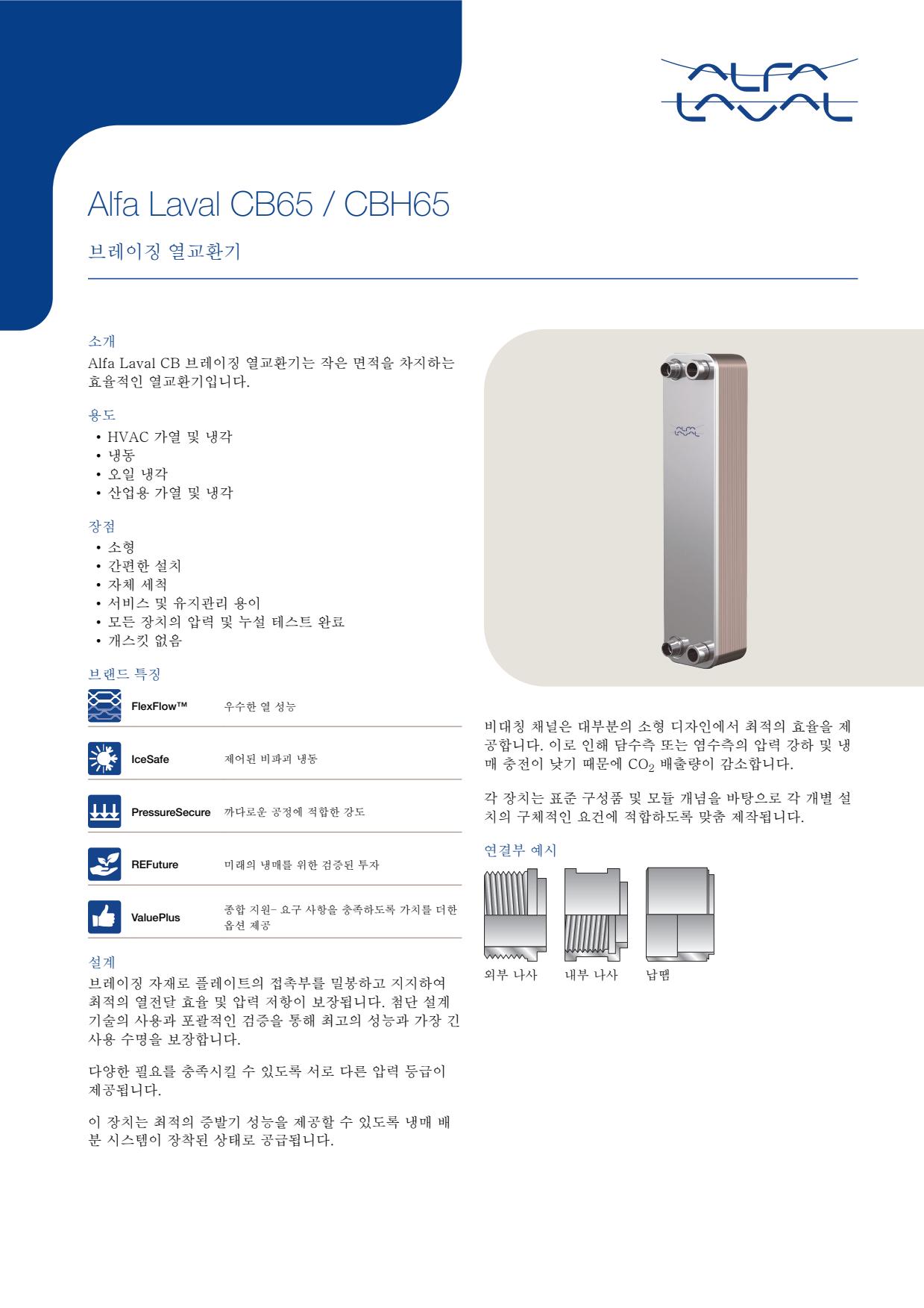
- Fouling or scaling inside the narrow plate channels reduces heat-transfer performance and increases pressure drop
- Blocked strainers or restricted upstream piping reduce flow and produce abnormal outlet temperatures
- Corrosion, erosion or fatigue damage to the bonded plate pack can cause internal cross-contamination between circuits
- External leakage at connections caused by damaged joints, vibration or piping loads produces visible fluid loss
- Freezing, thermal shock or operation outside the approved pressure and temperature envelope can damage the plate pack and lead to leakage
- Fouling or scaling inside the narrow plate channels reduces heat-transfer performance and increases pressure drop
- Blocked strainers or restricted upstream piping reduce flow and produce abnormal outlet temperatures
- Corrosion, erosion or fatigue damage to the bonded plate pack can cause internal cross-contamination between circuits
- External leakage at connections caused by damaged joints, vibration or piping loads produces visible fluid loss
- Freezing, thermal shock or operation outside the approved pressure and temperature envelope can damage the plate pack and lead to leakage
- Fouling or scaling inside the narrow plate channels reduces heat-transfer performance and increases pressure drop
- Blocked strainers or restricted upstream piping reduce flow and produce abnormal outlet temperatures
- Corrosion, erosion or fatigue damage to the bonded plate pack can cause internal cross-contamination between circuits
- External leakage at connections caused by damaged joints, vibration or piping loads produces visible fluid loss
- Freezing, thermal shock or operation outside the approved pressure and temperature envelope can damage the plate pack and lead to leakage
- Fouling or scaling inside the narrow plate channels reduces heat-transfer performance and increases pressure drop
- Blocked strainers or restricted upstream piping reduce flow and produce abnormal outlet temperatures
- Corrosion, erosion or fatigue damage to the bonded plate pack can cause internal cross-contamination between circuits
- External leakage at connections caused by damaged joints, vibration or piping loads produces visible fluid loss
- Freezing, thermal shock or operation outside the approved pressure and temperature envelope can damage the plate pack and lead to leakage
- Fouling or scaling inside the narrow plate channels reduces heat-transfer performance and increases pressure drop
- Blocked strainers or restricted upstream piping reduce flow and produce abnormal outlet temperatures
- Corrosion, erosion or fatigue damage to the bonded plate pack can cause internal cross-contamination between circuits
- External leakage at connections caused by damaged joints, vibration or piping loads produces visible fluid loss
- Freezing, thermal shock or operation outside the approved pressure and temperature envelope can damage the plate pack and lead to leakage
- Fouling or scaling inside the narrow plate channels reduces heat-transfer performance and increases pressure drop
- Blocked strainers or restricted upstream piping reduce flow and produce abnormal outlet temperatures
- Corrosion, erosion or fatigue damage to the bonded plate pack can cause internal cross-contamination between circuits
- External leakage at connections caused by damaged joints, vibration or piping loads produces visible fluid loss
- Freezing, thermal shock or operation outside the approved pressure and temperature envelope can damage the plate pack and lead to leakage
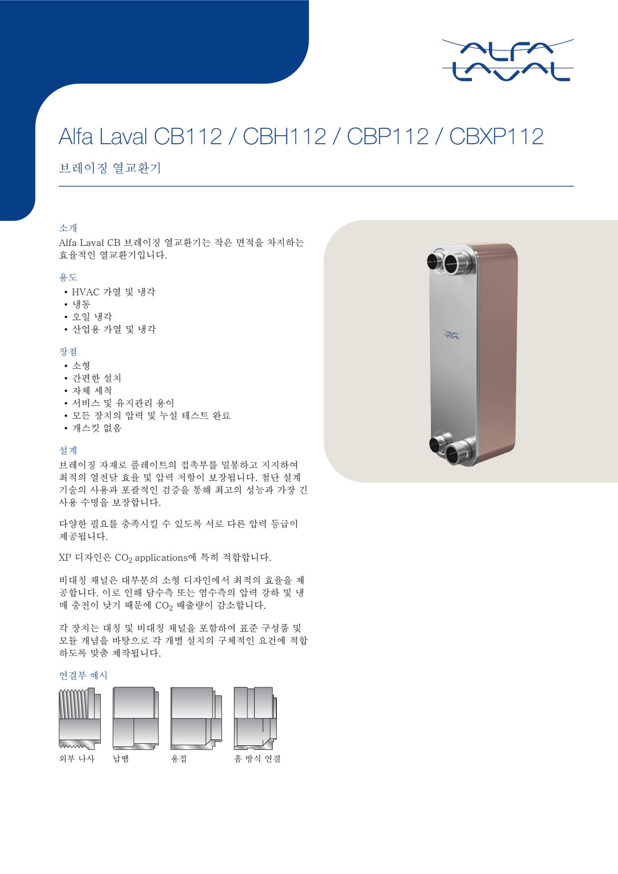
- Fouling or scaling inside the narrow plate channels reduces heat-transfer performance and increases pressure drop
- Blocked strainers or restricted upstream piping reduce flow and produce abnormal outlet temperatures
- Corrosion, erosion or fatigue damage to the bonded plate pack can cause internal cross-contamination between circuits
- External leakage at connections caused by damaged joints, vibration or piping loads produces visible fluid loss
- Freezing, thermal shock or operation outside the approved pressure and temperature envelope can damage the plate pack and lead to leakage
- Fouling or scaling inside the narrow plate channels reduces heat-transfer performance and increases pressure drop
- Blocked strainers or restricted upstream piping reduce flow and produce abnormal outlet temperatures
- Corrosion, erosion or fatigue damage to the bonded plate pack can cause internal cross-contamination between circuits
- External leakage at connections caused by damaged joints, vibration or piping loads produces visible fluid loss
- Freezing, thermal shock or operation outside the approved pressure and temperature envelope can damage the plate pack and lead to leakage
- Fouling or scaling inside the narrow plate channels reduces heat-transfer performance and increases pressure drop
- Blocked strainers or restricted upstream piping reduce flow and produce abnormal outlet temperatures
- Corrosion, erosion or fatigue damage to the bonded plate pack can cause internal cross-contamination between circuits
- External leakage at connections caused by damaged joints, vibration or piping loads produces visible fluid loss
- Freezing, thermal shock or operation outside the approved pressure and temperature envelope can damage the plate pack and lead to leakage
- Fouling or scaling inside the narrow plate channels reduces heat-transfer performance and increases pressure drop
- Blocked strainers or restricted upstream piping reduce flow and produce abnormal outlet temperatures
- Corrosion, erosion or fatigue damage to the bonded plate pack can cause internal cross-contamination between circuits
- External leakage at connections caused by damaged joints, vibration or piping loads produces visible fluid loss
- Freezing, thermal shock or operation outside the approved pressure and temperature envelope can damage the plate pack and lead to leakage
- Fouling or scaling inside the narrow plate channels reduces heat-transfer performance and increases pressure drop
- Blocked strainers or restricted upstream piping reduce flow and produce abnormal outlet temperatures
- Corrosion, erosion or fatigue damage to the bonded plate pack can cause internal cross-contamination between circuits
- External leakage at connections caused by damaged joints, vibration or piping loads produces visible fluid loss
- Freezing, thermal shock or operation outside the approved pressure and temperature envelope can damage the plate pack and lead to leakage
- Fouling or scaling inside the narrow plate channels reduces heat-transfer performance and increases pressure drop
- Blocked strainers or restricted upstream piping reduce flow and produce abnormal outlet temperatures
- Corrosion, erosion or fatigue damage to the bonded plate pack can cause internal cross-contamination between circuits
- External leakage at connections caused by damaged joints, vibration or piping loads produces visible fluid loss
- Freezing, thermal shock or operation outside the approved pressure and temperature envelope can damage the plate pack and lead to leakage
- Fouling or scaling inside the narrow plate channels reduces heat-transfer performance and increases pressure drop
- Blocked strainers or restricted upstream piping reduce flow and produce abnormal outlet temperatures
- Corrosion, erosion or fatigue damage to the bonded plate pack can cause internal cross-contamination between circuits
- External leakage at connections caused by damaged joints, vibration or piping loads produces visible fluid loss
- Freezing, thermal shock or operation outside the approved pressure and temperature envelope can damage the plate pack and lead to leakage
- Fouling or scaling inside the narrow plate channels reduces heat-transfer performance and increases pressure drop
- Blocked strainers or restricted upstream piping reduce flow and produce abnormal outlet temperatures
- Corrosion, erosion or fatigue damage to the bonded plate pack can cause internal cross-contamination between circuits
- External leakage at connections caused by damaged joints, vibration or piping loads produces visible fluid loss
- Freezing, thermal shock or operation outside the approved pressure and temperature envelope can damage the plate pack and lead to leakage
- Fouling or scaling inside the narrow plate channels reduces heat-transfer performance and increases pressure drop
- Blocked strainers or restricted upstream piping reduce flow and produce abnormal outlet temperatures
- Corrosion, erosion or fatigue damage to the bonded plate pack can cause internal cross-contamination between circuits
- External leakage at connections caused by damaged joints, vibration or piping loads produces visible fluid loss
- Freezing, thermal shock or operation outside the approved pressure and temperature envelope can damage the plate pack and lead to leakage
- Fouling or scaling inside the narrow plate channels reduces heat-transfer performance and increases pressure drop
- Blocked strainers or restricted upstream piping reduce flow and produce abnormal outlet temperatures
- Corrosion, erosion or fatigue damage to the bonded plate pack can cause internal cross-contamination between circuits
- External leakage at connections caused by damaged joints, vibration or piping loads produces visible fluid loss
- Freezing, thermal shock or operation outside the approved pressure and temperature envelope can damage the plate pack and lead to leakage
- Fouling or scaling inside the narrow plate channels reduces heat-transfer performance and increases pressure drop
- Blocked strainers or restricted upstream piping reduce flow and produce abnormal outlet temperatures
- Corrosion, erosion or fatigue damage to the bonded plate pack can cause internal cross-contamination between circuits
- External leakage at connections caused by damaged joints, vibration or piping loads produces visible fluid loss
- Freezing, thermal shock or operation outside the approved pressure and temperature envelope can damage the plate pack and lead to leakage
- Fouling or scaling inside the narrow plate channels reduces heat-transfer performance and increases pressure drop
- Blocked strainers or restricted upstream piping reduce flow and produce abnormal outlet temperatures
- Corrosion, erosion or fatigue damage to the bonded plate pack can cause internal cross-contamination between circuits
- External leakage at connections caused by damaged joints, vibration or piping loads produces visible fluid loss
- Freezing, thermal shock or operation outside the approved pressure and temperature envelope can damage the plate pack and lead to leakage
- Fouling or scaling inside the narrow plate channels reduces heat-transfer performance and increases pressure drop
- Blocked strainers or restricted upstream piping reduce flow and produce abnormal outlet temperatures
- Corrosion, erosion or fatigue damage to the bonded plate pack can cause internal cross-contamination between circuits
- External leakage at connections caused by damaged joints, vibration or piping loads produces visible fluid loss
- Freezing, thermal shock or operation outside the approved pressure and temperature envelope can damage the plate pack and lead to leakage
- Fouling or scaling inside the narrow plate channels reduces heat-transfer performance and increases pressure drop
- Blocked strainers or restricted upstream piping reduce flow and produce abnormal outlet temperatures
- Corrosion, erosion or fatigue damage to the bonded plate pack can cause internal cross-contamination between circuits
- External leakage at connections caused by damaged joints, vibration or piping loads produces visible fluid loss
- Freezing, thermal shock or operation outside the approved pressure and temperature envelope can damage the plate pack and lead to leakage
- Fouling or scaling inside the narrow plate channels reduces heat-transfer performance and increases pressure drop
- Blocked strainers or restricted upstream piping reduce flow and produce abnormal outlet temperatures
- Corrosion, erosion or fatigue damage to the bonded plate pack can cause internal cross-contamination between circuits
- External leakage at connections caused by damaged joints, vibration or piping loads produces visible fluid loss
- Freezing, thermal shock or operation outside the approved pressure and temperature envelope can damage the plate pack and lead to leakage
- Fouling, oil films or contamination on the fluid side reduce heat transfer and can cause abnormal approach temperatures
- Restricted strainers, poor refrigerant distribution or insufficient liquid flow causes unstable temperatures and reduced capacity
- Fatigue, corrosion or damage to the bonded plate pack can create internal leakage between circuits, detected by contamination, pressure behaviour or loss of charge
- External leakage at connections caused by vibration, thermal cycling or piping loads produces visible fluid loss or refrigerant alarms
- Freezing, liquid hammer or operation outside the approved pressure and temperature envelope can permanently damage the plate pack
- Fouling or scaling inside the narrow plate channels reduces heat-transfer performance and increases pressure drop
- Blocked strainers or restricted upstream piping reduce flow and produce abnormal outlet temperatures
- Corrosion, erosion or fatigue damage to the bonded plate pack can cause internal cross-contamination between circuits
- External leakage at connections caused by damaged joints, vibration or piping loads produces visible fluid loss
- Freezing, thermal shock or operation outside the approved pressure and temperature envelope can damage the plate pack and lead to leakage
- Fouling or scaling inside the narrow plate channels reduces heat-transfer performance and increases pressure drop
- Blocked strainers or restricted upstream piping reduce flow and produce abnormal outlet temperatures
- Corrosion, erosion or fatigue damage to the bonded plate pack can cause internal cross-contamination between circuits
- External leakage at connections caused by damaged joints, vibration or piping loads produces visible fluid loss
- Freezing, thermal shock or operation outside the approved pressure and temperature envelope can damage the plate pack and lead to leakage
- Fouling or scaling inside the narrow plate channels reduces heat-transfer performance and increases pressure drop
- Blocked strainers or restricted upstream piping reduce flow and produce abnormal outlet temperatures
- Corrosion, erosion or fatigue damage to the bonded plate pack can cause internal cross-contamination between circuits
- External leakage at connections caused by damaged joints, vibration or piping loads produces visible fluid loss
- Freezing, thermal shock or operation outside the approved pressure and temperature envelope can damage the plate pack and lead to leakage
- Fouling or scaling inside the narrow plate channels reduces heat-transfer performance and increases pressure drop
- Blocked strainers or restricted upstream piping reduce flow and produce abnormal outlet temperatures
- Corrosion, erosion or fatigue damage to the bonded plate pack can cause internal cross-contamination between circuits
- External leakage at connections caused by damaged joints, vibration or piping loads produces visible fluid loss
- Freezing, thermal shock or operation outside the approved pressure and temperature envelope can damage the plate pack and lead to leakage
- Fouling or scaling inside the narrow plate channels reduces heat-transfer performance and increases pressure drop
- Blocked strainers or restricted upstream piping reduce flow and produce abnormal outlet temperatures
- Corrosion, erosion or fatigue damage to the bonded plate pack can cause internal cross-contamination between circuits
- External leakage at connections caused by damaged joints, vibration or piping loads produces visible fluid loss
- Freezing, thermal shock or operation outside the approved pressure and temperature envelope can damage the plate pack and lead to leakage
- Fouling or scaling inside the narrow plate channels reduces heat-transfer performance and increases pressure drop
- Blocked strainers or restricted upstream piping reduce flow and produce abnormal outlet temperatures
- Corrosion, erosion or fatigue damage to the bonded plate pack can cause internal cross-contamination between circuits
- External leakage at connections caused by damaged joints, vibration or piping loads produces visible fluid loss
- Freezing, thermal shock or operation outside the approved pressure and temperature envelope can damage the plate pack and lead to leakage
- Fouling or scaling inside the narrow plate channels reduces heat-transfer performance and increases pressure drop
- Blocked strainers or restricted upstream piping reduce flow and produce abnormal outlet temperatures
- Corrosion, erosion or fatigue damage to the bonded plate pack can cause internal cross-contamination between circuits
- External leakage at connections caused by damaged joints, vibration or piping loads produces visible fluid loss
- Freezing, thermal shock or operation outside the approved pressure and temperature envelope can damage the plate pack and lead to leakage
- Fouling or scaling inside the narrow plate channels reduces heat-transfer performance and increases pressure drop
- Blocked strainers or restricted upstream piping reduce flow and produce abnormal outlet temperatures
- Corrosion, erosion or fatigue damage to the bonded plate pack can cause internal cross-contamination between circuits
- External leakage at connections caused by damaged joints, vibration or piping loads produces visible fluid loss
- Freezing, thermal shock or operation outside the approved pressure and temperature envelope can damage the plate pack and lead to leakage
- Fouling or scaling inside the narrow plate channels reduces heat-transfer performance and increases pressure drop
- Blocked strainers or restricted upstream piping reduce flow and produce abnormal outlet temperatures
- Corrosion, erosion or fatigue damage to the bonded plate pack can cause internal cross-contamination between circuits
- External leakage at connections caused by damaged joints, vibration or piping loads produces visible fluid loss
- Freezing, thermal shock or operation outside the approved pressure and temperature envelope can damage the plate pack and lead to leakage
- Fouling or scaling inside the narrow plate channels reduces heat-transfer performance and increases pressure drop
- Blocked strainers or restricted upstream piping reduce flow and produce abnormal outlet temperatures
- Corrosion, erosion or fatigue damage to the bonded plate pack can cause internal cross-contamination between circuits
- External leakage at connections caused by damaged joints, vibration or piping loads produces visible fluid loss
- Freezing, thermal shock or operation outside the approved pressure and temperature envelope can damage the plate pack and lead to leakage
- Fouling or scaling inside the narrow plate channels reduces heat-transfer performance and increases pressure drop
- Blocked strainers or restricted upstream piping reduce flow and produce abnormal outlet temperatures
- Corrosion, erosion or fatigue damage to the bonded plate pack can cause internal cross-contamination between circuits
- External leakage at connections caused by damaged joints, vibration or piping loads produces visible fluid loss
- Freezing, thermal shock or operation outside the approved pressure and temperature envelope can damage the plate pack and lead to leakage
- Fouling or scaling inside the narrow plate channels reduces heat-transfer performance and increases pressure drop
- Blocked strainers or restricted upstream piping reduce flow and produce abnormal outlet temperatures
- Corrosion, erosion or fatigue damage to the bonded plate pack can cause internal cross-contamination between circuits
- External leakage at connections caused by damaged joints, vibration or piping loads produces visible fluid loss
- Freezing, thermal shock or operation outside the approved pressure and temperature envelope can damage the plate pack and lead to leakage
- Fouling or scaling inside the narrow plate channels reduces heat-transfer performance and increases pressure drop
- Blocked strainers or restricted upstream piping reduce flow and produce abnormal outlet temperatures
- Corrosion, erosion or fatigue damage to the bonded plate pack can cause internal cross-contamination between circuits
- External leakage at connections caused by damaged joints, vibration or piping loads produces visible fluid loss
- Freezing, thermal shock or operation outside the approved pressure and temperature envelope can damage the plate pack and lead to leakage
- Fouling or scaling inside the narrow plate channels reduces heat-transfer performance and increases pressure drop
- Blocked strainers or restricted upstream piping reduce flow and produce abnormal outlet temperatures
- Corrosion, erosion or fatigue damage to the bonded plate pack can cause internal cross-contamination between circuits
- External leakage at connections caused by damaged joints, vibration or piping loads produces visible fluid loss
- Freezing, thermal shock or operation outside the approved pressure and temperature envelope can damage the plate pack and lead to leakage
- Fouling or scaling inside the narrow plate channels reduces heat-transfer performance and increases pressure drop
- Blocked strainers or restricted upstream piping reduce flow and produce abnormal outlet temperatures
- Corrosion, erosion or fatigue damage to the bonded plate pack can cause internal cross-contamination between circuits
- External leakage at connections caused by damaged joints, vibration or piping loads produces visible fluid loss
- Freezing, thermal shock or operation outside the approved pressure and temperature envelope can damage the plate pack and lead to leakage
- Fouling or scaling inside the narrow plate channels reduces heat-transfer performance and increases pressure drop
- Blocked strainers or restricted upstream piping reduce flow and produce abnormal outlet temperatures
- Corrosion, erosion or fatigue damage to the bonded plate pack can cause internal cross-contamination between circuits
- External leakage at connections caused by damaged joints, vibration or piping loads produces visible fluid loss
- Freezing, thermal shock or operation outside the approved pressure and temperature envelope can damage the plate pack and lead to leakage
- Fouling or scaling inside the narrow plate channels reduces heat-transfer performance and increases pressure drop
- Blocked strainers or restricted upstream piping reduce flow and produce abnormal outlet temperatures
- Corrosion, erosion or fatigue damage to the bonded plate pack can cause internal cross-contamination between circuits
- External leakage at connections caused by damaged joints, vibration or piping loads produces visible fluid loss
- Freezing, thermal shock or operation outside the approved pressure and temperature envelope can damage the plate pack and lead to leakage
- Fouling or scaling inside the narrow plate channels reduces heat-transfer performance and increases pressure drop
- Blocked strainers or restricted upstream piping reduce flow and produce abnormal outlet temperatures
- Corrosion, erosion or fatigue damage to the bonded plate pack can cause internal cross-contamination between circuits
- External leakage at connections caused by damaged joints, vibration or piping loads produces visible fluid loss
- Freezing, thermal shock or operation outside the approved pressure and temperature envelope can damage the plate pack and lead to leakage
- Fouling or scaling inside the narrow plate channels reduces heat-transfer performance and increases pressure drop
- Blocked strainers or restricted upstream piping reduce flow and produce abnormal outlet temperatures
- Corrosion, erosion or fatigue damage to the bonded plate pack can cause internal cross-contamination between circuits
- External leakage at connections caused by damaged joints, vibration or piping loads produces visible fluid loss
- Freezing, thermal shock or operation outside the approved pressure and temperature envelope can damage the plate pack and lead to leakage
- Fouling or scaling inside the narrow plate channels reduces heat-transfer performance and increases pressure drop
- Blocked strainers or restricted upstream piping reduce flow and produce abnormal outlet temperatures
- Corrosion, erosion or fatigue damage to the bonded plate pack can cause internal cross-contamination between circuits
- External leakage at connections caused by damaged joints, vibration or piping loads produces visible fluid loss
- Freezing, thermal shock or operation outside the approved pressure and temperature envelope can damage the plate pack and lead to leakage
- Fouling or scaling inside the narrow plate channels reduces heat-transfer performance and increases pressure drop
- Blocked strainers or restricted upstream piping reduce flow and produce abnormal outlet temperatures
- Corrosion, erosion or fatigue damage to the bonded plate pack can cause internal cross-contamination between circuits
- External leakage at connections caused by damaged joints, vibration or piping loads produces visible fluid loss
- Freezing, thermal shock or operation outside the approved pressure and temperature envelope can damage the plate pack and lead to leakage
- Fouling or scaling inside the narrow plate channels reduces heat-transfer performance and increases pressure drop
- Blocked strainers or restricted upstream piping reduce flow and produce abnormal outlet temperatures
- Corrosion, erosion or fatigue damage to the bonded plate pack can cause internal cross-contamination between circuits
- External leakage at connections caused by damaged joints, vibration or piping loads produces visible fluid loss
- Freezing, thermal shock or operation outside the approved pressure and temperature envelope can damage the plate pack and lead to leakage
- Fouling or scaling inside the narrow plate channels reduces heat-transfer performance and increases pressure drop
- Blocked strainers or restricted upstream piping reduce flow and produce abnormal outlet temperatures
- Corrosion, erosion or fatigue damage to the bonded plate pack can cause internal cross-contamination between circuits
- External leakage at connections caused by damaged joints, vibration or piping loads produces visible fluid loss
- Freezing, thermal shock or operation outside the approved pressure and temperature envelope can damage the plate pack and lead to leakage
- Fouling or scaling inside the narrow plate channels reduces heat-transfer performance and increases pressure drop
- Blocked strainers or restricted upstream piping reduce flow and produce abnormal outlet temperatures
- Corrosion, erosion or fatigue damage to the bonded plate pack can cause internal cross-contamination between circuits
- External leakage at connections caused by damaged joints, vibration or piping loads produces visible fluid loss
- Freezing, thermal shock or operation outside the approved pressure and temperature envelope can damage the plate pack and lead to leakage
- Fouling or scaling inside the narrow plate channels reduces heat-transfer performance and increases pressure drop
- Blocked strainers or restricted upstream piping reduce flow and produce abnormal outlet temperatures
- Corrosion, erosion or fatigue damage to the bonded plate pack can cause internal cross-contamination between circuits
- External leakage at connections caused by damaged joints, vibration or piping loads produces visible fluid loss
- Freezing, thermal shock or operation outside the approved pressure and temperature envelope can damage the plate pack and lead to leakage
- Fouling or scaling inside the narrow plate channels reduces heat-transfer performance and increases pressure drop
- Blocked strainers or restricted upstream piping reduce flow and produce abnormal outlet temperatures
- Corrosion, erosion or fatigue damage to the bonded plate pack can cause internal cross-contamination between circuits
- External leakage at connections caused by damaged joints, vibration or piping loads produces visible fluid loss
- Freezing, thermal shock or operation outside the approved pressure and temperature envelope can damage the plate pack and lead to leakage
- Fouling or scaling inside the narrow plate channels reduces heat-transfer performance and increases pressure drop
- Blocked strainers or restricted upstream piping reduce flow and produce abnormal outlet temperatures
- Corrosion, erosion or fatigue damage to the bonded plate pack can cause internal cross-contamination between circuits
- External leakage at connections caused by damaged joints, vibration or piping loads produces visible fluid loss
- Freezing, thermal shock or operation outside the approved pressure and temperature envelope can damage the plate pack and lead to leakage
- Fouling or scaling inside the narrow plate channels reduces heat-transfer performance and increases pressure drop
- Blocked strainers or restricted upstream piping reduce flow and produce abnormal outlet temperatures
- Corrosion, erosion or fatigue damage to the bonded plate pack can cause internal cross-contamination between circuits
- External leakage at connections caused by damaged joints, vibration or piping loads produces visible fluid loss
- Freezing, thermal shock or operation outside the approved pressure and temperature envelope can damage the plate pack and lead to leakage
- Fouling or scaling inside the narrow plate channels reduces heat-transfer performance and increases pressure drop
- Blocked strainers or restricted upstream piping reduce flow and produce abnormal outlet temperatures
- Corrosion, erosion or fatigue damage to the bonded plate pack can cause internal cross-contamination between circuits
- External leakage at connections caused by damaged joints, vibration or piping loads produces visible fluid loss
- Freezing, thermal shock or operation outside the approved pressure and temperature envelope can damage the plate pack and lead to leakage
- Fouling or scaling inside the narrow plate channels reduces heat-transfer performance and increases pressure drop
- Blocked strainers or restricted upstream piping reduce flow and produce abnormal outlet temperatures
- Corrosion, erosion or fatigue damage to the bonded plate pack can cause internal cross-contamination between circuits
- External leakage at connections caused by damaged joints, vibration or piping loads produces visible fluid loss
- Freezing, thermal shock or operation outside the approved pressure and temperature envelope can damage the plate pack and lead to leakage
- Fouling or scaling inside the narrow plate channels reduces heat-transfer performance and increases pressure drop
- Blocked strainers or restricted upstream piping reduce flow and produce abnormal outlet temperatures
- Corrosion, erosion or fatigue damage to the bonded plate pack can cause internal cross-contamination between circuits
- External leakage at connections caused by damaged joints, vibration or piping loads produces visible fluid loss
- Freezing, thermal shock or operation outside the approved pressure and temperature envelope can damage the plate pack and lead to leakage
- Fouling or scaling inside the narrow plate channels reduces heat-transfer performance and increases pressure drop
- Blocked strainers or restricted upstream piping reduce flow and produce abnormal outlet temperatures
- Corrosion, erosion or fatigue damage to the bonded plate pack can cause internal cross-contamination between circuits
- External leakage at connections caused by damaged joints, vibration or piping loads produces visible fluid loss
- Freezing, thermal shock or operation outside the approved pressure and temperature envelope can damage the plate pack and lead to leakage
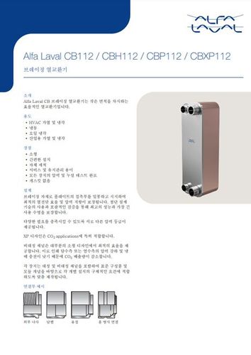
- Fouling or scaling inside the narrow plate channels reduces heat-transfer performance and increases pressure drop
- Blocked strainers or restricted upstream piping reduce flow and produce abnormal outlet temperatures
- Corrosion, erosion or fatigue damage to the bonded plate pack can cause internal cross-contamination between circuits
- External leakage at connections caused by damaged joints, vibration or piping loads produces visible fluid loss
- Freezing, thermal shock or operation outside the approved pressure and temperature envelope can damage the plate pack and lead to leakage
- Fouling or scaling inside the narrow plate channels reduces heat-transfer performance and increases pressure drop
- Blocked strainers or restricted upstream piping reduce flow and produce abnormal outlet temperatures
- Corrosion, erosion or fatigue damage to the bonded plate pack can cause internal cross-contamination between circuits
- External leakage at connections caused by damaged joints, vibration or piping loads produces visible fluid loss
- Freezing, thermal shock or operation outside the approved pressure and temperature envelope can damage the plate pack and lead to leakage
- Fouling or scaling inside the narrow plate channels reduces heat-transfer performance and increases pressure drop
- Blocked strainers or restricted upstream piping reduce flow and produce abnormal outlet temperatures
- Corrosion, erosion or fatigue damage to the bonded plate pack can cause internal cross-contamination between circuits
- External leakage at connections caused by damaged joints, vibration or piping loads produces visible fluid loss
- Freezing, thermal shock or operation outside the approved pressure and temperature envelope can damage the plate pack and lead to leakage
- Fouling or scaling inside the narrow plate channels reduces heat-transfer performance and increases pressure drop
- Blocked strainers or restricted upstream piping reduce flow and produce abnormal outlet temperatures
- Corrosion, erosion or fatigue damage to the bonded plate pack can cause internal cross-contamination between circuits
- External leakage at connections caused by damaged joints, vibration or piping loads produces visible fluid loss
- Freezing, thermal shock or operation outside the approved pressure and temperature envelope can damage the plate pack and lead to leakage
- Fouling or scaling inside the narrow plate channels reduces heat-transfer performance and increases pressure drop
- Blocked strainers or restricted upstream piping reduce flow and produce abnormal outlet temperatures
- Corrosion, erosion or fatigue damage to the bonded plate pack can cause internal cross-contamination between circuits
- External leakage at connections caused by damaged joints, vibration or piping loads produces visible fluid loss
- Freezing, thermal shock or operation outside the approved pressure and temperature envelope can damage the plate pack and lead to leakage
- Fouling or scaling inside the narrow plate channels reduces heat-transfer performance and increases pressure drop
- Blocked strainers or restricted upstream piping reduce flow and produce abnormal outlet temperatures
- Corrosion, erosion or fatigue damage to the bonded plate pack can cause internal cross-contamination between circuits
- External leakage at connections caused by damaged joints, vibration or piping loads produces visible fluid loss
- Freezing, thermal shock or operation outside the approved pressure and temperature envelope can damage the plate pack and lead to leakage
- Fouling or scaling inside the narrow plate channels reduces heat-transfer performance and increases pressure drop
- Blocked strainers or restricted upstream piping reduce flow and produce abnormal outlet temperatures
- Corrosion, erosion or fatigue damage to the bonded plate pack can cause internal cross-contamination between circuits
- External leakage at connections caused by damaged joints, vibration or piping loads produces visible fluid loss
- Freezing, thermal shock or operation outside the approved pressure and temperature envelope can damage the plate pack and lead to leakage
- Fouling or scaling inside the narrow plate channels reduces heat-transfer performance and increases pressure drop
- Blocked strainers or restricted upstream piping reduce flow and produce abnormal outlet temperatures
- Corrosion, erosion or fatigue damage to the bonded plate pack can cause internal cross-contamination between circuits
- External leakage at connections caused by damaged joints, vibration or piping loads produces visible fluid loss
- Freezing, thermal shock or operation outside the approved pressure and temperature envelope can damage the plate pack and lead to leakage
- Fouling or scaling inside the narrow plate channels reduces heat-transfer performance and increases pressure drop
- Blocked strainers or restricted upstream piping reduce flow and produce abnormal outlet temperatures
- Corrosion, erosion or fatigue damage to the bonded plate pack can cause internal cross-contamination between circuits
- External leakage at connections caused by damaged joints, vibration or piping loads produces visible fluid loss
- Freezing, thermal shock or operation outside the approved pressure and temperature envelope can damage the plate pack and lead to leakage
- Fouling or scaling inside the narrow plate channels reduces heat-transfer performance and increases pressure drop
- Blocked strainers or restricted upstream piping reduce flow and produce abnormal outlet temperatures
- Corrosion, erosion or fatigue damage to the bonded plate pack can cause internal cross-contamination between circuits
- External leakage at connections caused by damaged joints, vibration or piping loads produces visible fluid loss
- Freezing, thermal shock or operation outside the approved pressure and temperature envelope can damage the plate pack and lead to leakage
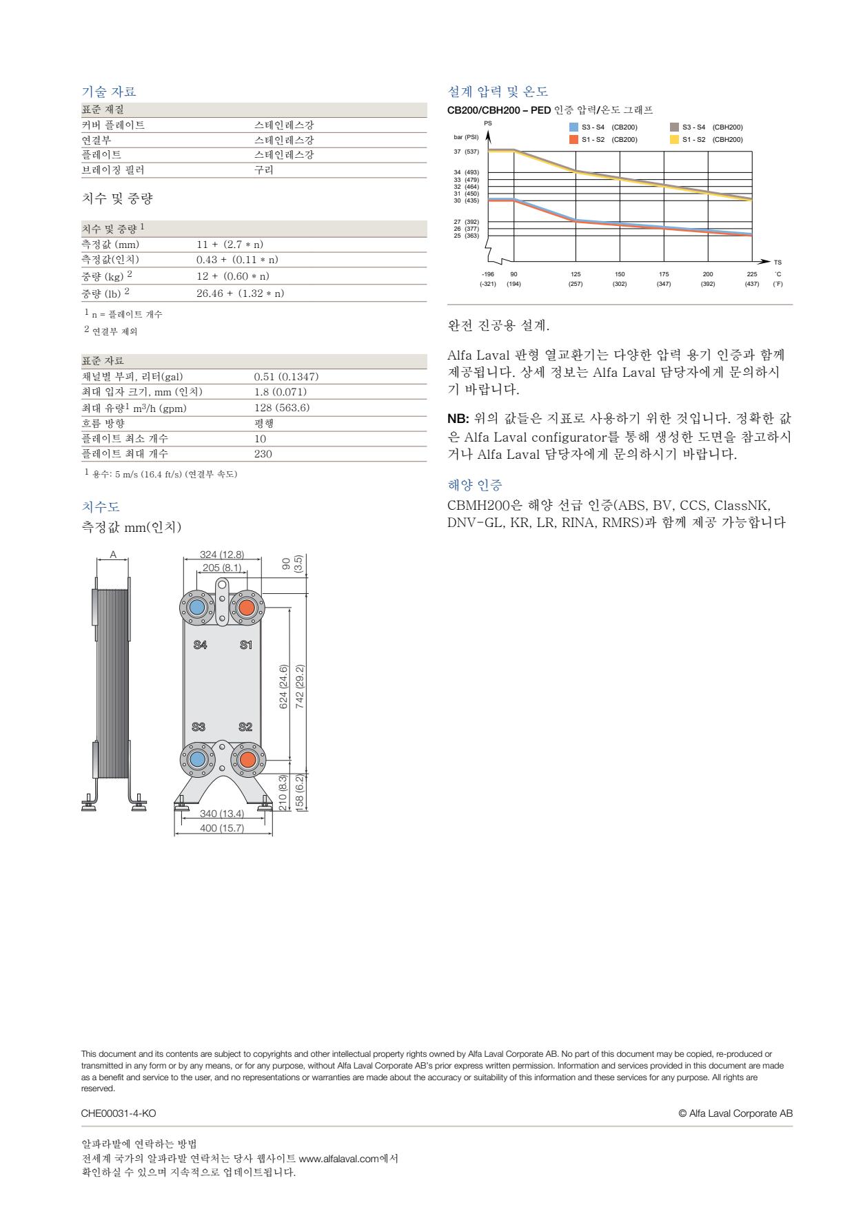
- Fouling or scaling inside the narrow plate channels reduces heat-transfer performance and increases pressure drop
- Blocked strainers or restricted upstream piping reduce flow and produce abnormal outlet temperatures
- Corrosion, erosion or fatigue damage to the bonded plate pack can cause internal cross-contamination between circuits
- External leakage at connections caused by damaged joints, vibration or piping loads produces visible fluid loss
- Freezing, thermal shock or operation outside the approved pressure and temperature envelope can damage the plate pack and lead to leakage
- Fouling or scaling inside the narrow plate channels reduces heat-transfer performance and increases pressure drop
- Blocked strainers or restricted upstream piping reduce flow and produce abnormal outlet temperatures
- Corrosion, erosion or fatigue damage to the bonded plate pack can cause internal cross-contamination between circuits
- External leakage at connections caused by damaged joints, vibration or piping loads produces visible fluid loss
- Freezing, thermal shock or operation outside the approved pressure and temperature envelope can damage the plate pack and lead to leakage
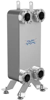
- Fouling or scaling inside the narrow plate channels reduces heat-transfer performance and increases pressure drop
- Blocked strainers or restricted upstream piping reduce flow and produce abnormal outlet temperatures
- Corrosion, erosion or fatigue damage to the bonded plate pack can cause internal cross-contamination between circuits
- External leakage at connections caused by damaged joints, vibration or piping loads produces visible fluid loss
- Freezing, thermal shock or operation outside the approved pressure and temperature envelope can damage the plate pack and lead to leakage
- Fouling or scaling inside the narrow plate channels reduces heat-transfer performance and increases pressure drop
- Blocked strainers or restricted upstream piping reduce flow and produce abnormal outlet temperatures
- Corrosion, erosion or fatigue damage to the bonded plate pack can cause internal cross-contamination between circuits
- External leakage at connections caused by damaged joints, vibration or piping loads produces visible fluid loss
- Freezing, thermal shock or operation outside the approved pressure and temperature envelope can damage the plate pack and lead to leakage
- Fouling or scaling inside the narrow plate channels reduces heat-transfer performance and increases pressure drop
- Blocked strainers or restricted upstream piping reduce flow and produce abnormal outlet temperatures
- Corrosion, erosion or fatigue damage to the bonded plate pack can cause internal cross-contamination between circuits
- External leakage at connections caused by damaged joints, vibration or piping loads produces visible fluid loss
- Freezing, thermal shock or operation outside the approved pressure and temperature envelope can damage the plate pack and lead to leakage
- Fouling or scaling inside the narrow plate channels reduces heat-transfer performance and increases pressure drop
- Blocked strainers or restricted upstream piping reduce flow and produce abnormal outlet temperatures
- Corrosion, erosion or fatigue damage to the bonded plate pack can cause internal cross-contamination between circuits
- External leakage at connections caused by damaged joints, vibration or piping loads produces visible fluid loss
- Freezing, thermal shock or operation outside the approved pressure and temperature envelope can damage the plate pack and lead to leakage
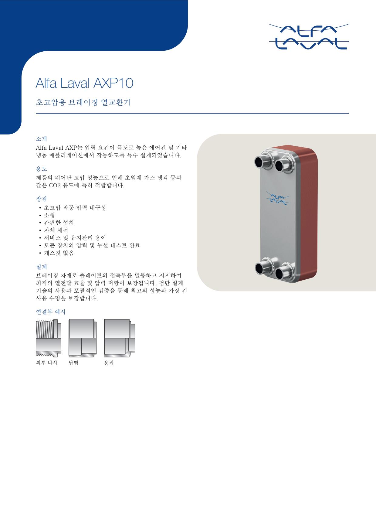
- Fouling, oil films or contamination on the fluid side reduce heat transfer and can cause abnormal approach temperatures
- Restricted strainers, poor refrigerant distribution or insufficient liquid flow causes unstable temperatures and reduced capacity
- Fatigue, corrosion or damage to the bonded plate pack can create internal leakage between circuits, detected by contamination, pressure behaviour or loss of charge
- External leakage at connections caused by vibration, thermal cycling or piping loads produces visible fluid loss or refrigerant alarms
- Freezing, liquid hammer or operation outside the approved pressure and temperature envelope can permanently damage the plate pack
- Fouling, oil films or contamination on the fluid side reduce heat transfer and can cause abnormal approach temperatures
- Restricted strainers, poor refrigerant distribution or insufficient liquid flow causes unstable temperatures and reduced capacity
- Fatigue, corrosion or damage to the bonded plate pack can create internal leakage between circuits, detected by contamination, pressure behaviour or loss of charge
- External leakage at connections caused by vibration, thermal cycling or piping loads produces visible fluid loss or refrigerant alarms
- Freezing, liquid hammer or operation outside the approved pressure and temperature envelope can permanently damage the plate pack
- Fouling, oil films or contamination on the fluid side reduce heat transfer and can cause abnormal approach temperatures
- Restricted strainers, poor refrigerant distribution or insufficient liquid flow causes unstable temperatures and reduced capacity
- Fatigue, corrosion or damage to the bonded plate pack can create internal leakage between circuits, detected by contamination, pressure behaviour or loss of charge
- External leakage at connections caused by vibration, thermal cycling or piping loads produces visible fluid loss or refrigerant alarms
- Freezing, liquid hammer or operation outside the approved pressure and temperature envelope can permanently damage the plate pack
- Fouling, oil films or contamination on the fluid side reduce heat transfer and can cause abnormal approach temperatures
- Restricted strainers, poor refrigerant distribution or insufficient liquid flow causes unstable temperatures and reduced capacity
- Fatigue, corrosion or damage to the bonded plate pack can create internal leakage between circuits, detected by contamination, pressure behaviour or loss of charge
- External leakage at connections caused by vibration, thermal cycling or piping loads produces visible fluid loss or refrigerant alarms
- Freezing, liquid hammer or operation outside the approved pressure and temperature envelope can permanently damage the plate pack
- Fouling, oil films or contamination on the fluid side reduce heat transfer and can cause abnormal approach temperatures
- Restricted strainers, poor refrigerant distribution or insufficient liquid flow causes unstable temperatures and reduced capacity
- Fatigue, corrosion or damage to the bonded plate pack can create internal leakage between circuits, detected by contamination, pressure behaviour or loss of charge
- External leakage at connections caused by vibration, thermal cycling or piping loads produces visible fluid loss or refrigerant alarms
- Freezing, liquid hammer or operation outside the approved pressure and temperature envelope can permanently damage the plate pack
- Fouling, oil films or contamination on the fluid side reduce heat transfer and can cause abnormal approach temperatures
- Restricted strainers, poor refrigerant distribution or insufficient liquid flow causes unstable temperatures and reduced capacity
- Fatigue, corrosion or damage to the bonded plate pack can create internal leakage between circuits, detected by contamination, pressure behaviour or loss of charge
- External leakage at connections caused by vibration, thermal cycling or piping loads produces visible fluid loss or refrigerant alarms
- Freezing, liquid hammer or operation outside the approved pressure and temperature envelope can permanently damage the plate pack
- Fouling, oil films or contamination on the fluid side reduce heat transfer and can cause abnormal approach temperatures
- Restricted strainers, poor refrigerant distribution or insufficient liquid flow causes unstable temperatures and reduced capacity
- Fatigue, corrosion or damage to the bonded plate pack can create internal leakage between circuits, detected by contamination, pressure behaviour or loss of charge
- External leakage at connections caused by vibration, thermal cycling or piping loads produces visible fluid loss or refrigerant alarms
- Freezing, liquid hammer or operation outside the approved pressure and temperature envelope can permanently damage the plate pack
- Fouling, oil films or contamination on the fluid side reduce heat transfer and can cause abnormal approach temperatures
- Restricted strainers, poor refrigerant distribution or insufficient liquid flow causes unstable temperatures and reduced capacity
- Fatigue, corrosion or damage to the bonded plate pack can create internal leakage between circuits, detected by contamination, pressure behaviour or loss of charge
- External leakage at connections caused by vibration, thermal cycling or piping loads produces visible fluid loss or refrigerant alarms
- Freezing, liquid hammer or operation outside the approved pressure and temperature envelope can permanently damage the plate pack
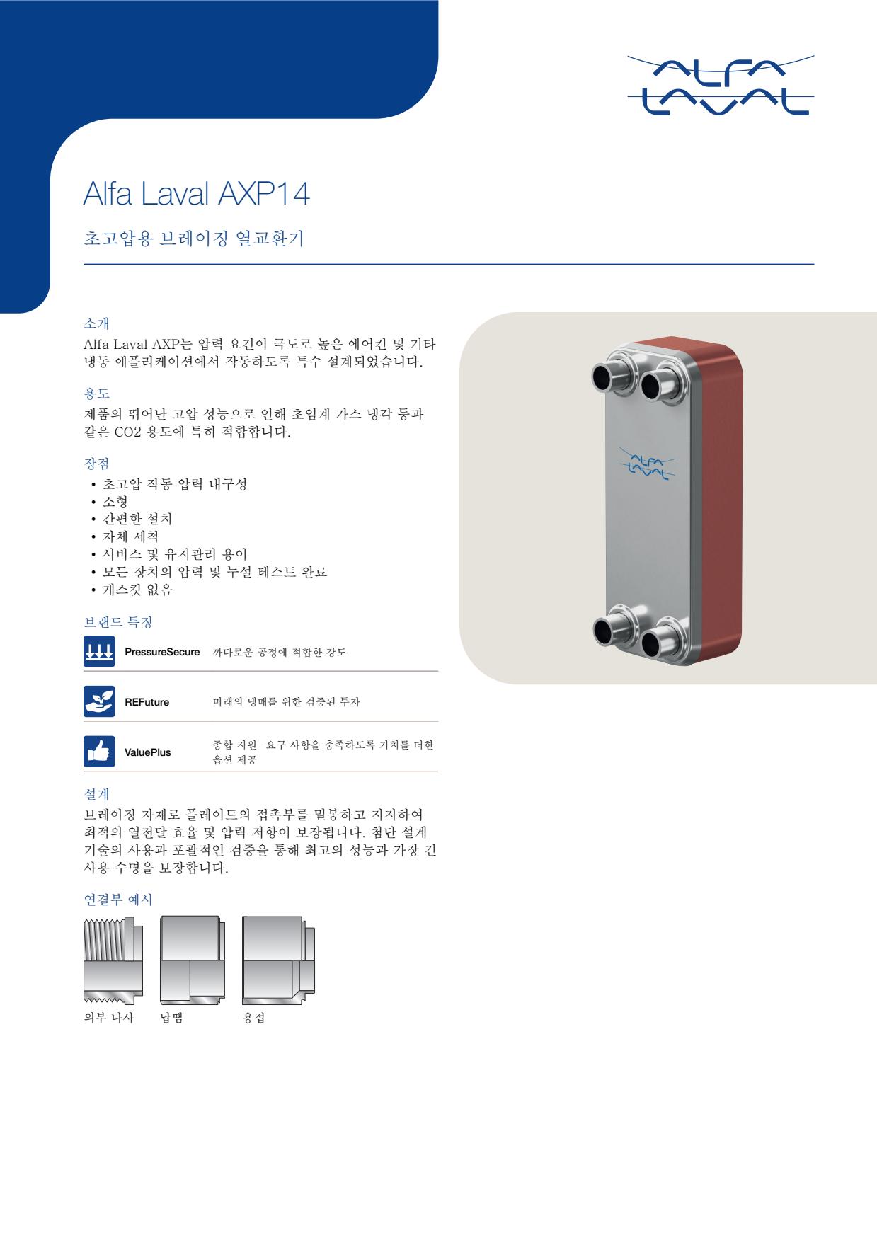
- Fouling, oil films or contamination on the fluid side reduce heat transfer and can cause abnormal approach temperatures
- Restricted strainers, poor refrigerant distribution or insufficient liquid flow causes unstable temperatures and reduced capacity
- Fatigue, corrosion or damage to the bonded plate pack can create internal leakage between circuits, detected by contamination, pressure behaviour or loss of charge
- External leakage at connections caused by vibration, thermal cycling or piping loads produces visible fluid loss or refrigerant alarms
- Freezing, liquid hammer or operation outside the approved pressure and temperature envelope can permanently damage the plate pack
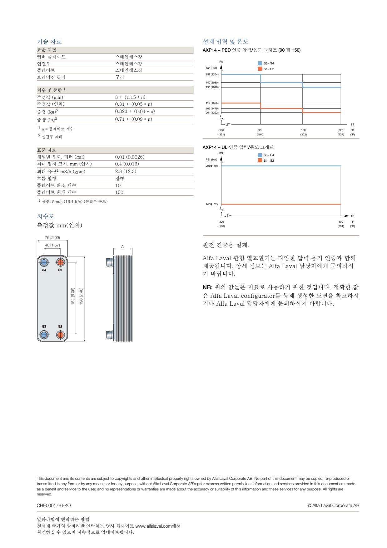
- Fouling, oil films or contamination on the fluid side reduce heat transfer and can cause abnormal approach temperatures
- Restricted strainers, poor refrigerant distribution or insufficient liquid flow causes unstable temperatures and reduced capacity
- Fatigue, corrosion or damage to the bonded plate pack can create internal leakage between circuits, detected by contamination, pressure behaviour or loss of charge
- External leakage at connections caused by vibration, thermal cycling or piping loads produces visible fluid loss or refrigerant alarms
- Freezing, liquid hammer or operation outside the approved pressure and temperature envelope can permanently damage the plate pack
- Fouling, oil films or contamination on the fluid side reduce heat transfer and can cause abnormal approach temperatures
- Restricted strainers, poor refrigerant distribution or insufficient liquid flow causes unstable temperatures and reduced capacity
- Fatigue, corrosion or damage to the bonded plate pack can create internal leakage between circuits, detected by contamination, pressure behaviour or loss of charge
- External leakage at connections caused by vibration, thermal cycling or piping loads produces visible fluid loss or refrigerant alarms
- Freezing, liquid hammer or operation outside the approved pressure and temperature envelope can permanently damage the plate pack
- Fouling, oil films or contamination on the fluid side reduce heat transfer and can cause abnormal approach temperatures
- Restricted strainers, poor refrigerant distribution or insufficient liquid flow causes unstable temperatures and reduced capacity
- Fatigue, corrosion or damage to the bonded plate pack can create internal leakage between circuits, detected by contamination, pressure behaviour or loss of charge
- External leakage at connections caused by vibration, thermal cycling or piping loads produces visible fluid loss or refrigerant alarms
- Freezing, liquid hammer or operation outside the approved pressure and temperature envelope can permanently damage the plate pack
- Fouling, oil films or contamination on the fluid side reduce heat transfer and can cause abnormal approach temperatures
- Restricted strainers, poor refrigerant distribution or insufficient liquid flow causes unstable temperatures and reduced capacity
- Fatigue, corrosion or damage to the bonded plate pack can create internal leakage between circuits, detected by contamination, pressure behaviour or loss of charge
- External leakage at connections caused by vibration, thermal cycling or piping loads produces visible fluid loss or refrigerant alarms
- Freezing, liquid hammer or operation outside the approved pressure and temperature envelope can permanently damage the plate pack
- Fouling, oil films or contamination on the fluid side reduce heat transfer and can cause abnormal approach temperatures
- Restricted strainers, poor refrigerant distribution or insufficient liquid flow causes unstable temperatures and reduced capacity
- Fatigue, corrosion or damage to the bonded plate pack can create internal leakage between circuits, detected by contamination, pressure behaviour or loss of charge
- External leakage at connections caused by vibration, thermal cycling or piping loads produces visible fluid loss or refrigerant alarms
- Freezing, liquid hammer or operation outside the approved pressure and temperature envelope can permanently damage the plate pack
- Fouling, oil films or contamination on the fluid side reduce heat transfer and can cause abnormal approach temperatures
- Restricted strainers, poor refrigerant distribution or insufficient liquid flow causes unstable temperatures and reduced capacity
- Fatigue, corrosion or damage to the bonded plate pack can create internal leakage between circuits, detected by contamination, pressure behaviour or loss of charge
- External leakage at connections caused by vibration, thermal cycling or piping loads produces visible fluid loss or refrigerant alarms
- Freezing, liquid hammer or operation outside the approved pressure and temperature envelope can permanently damage the plate pack
- Fouling, oil films or contamination on the fluid side reduce heat transfer and can cause abnormal approach temperatures
- Restricted strainers, poor refrigerant distribution or insufficient liquid flow causes unstable temperatures and reduced capacity
- Fatigue, corrosion or damage to the bonded plate pack can create internal leakage between circuits, detected by contamination, pressure behaviour or loss of charge
- External leakage at connections caused by vibration, thermal cycling or piping loads produces visible fluid loss or refrigerant alarms
- Freezing, liquid hammer or operation outside the approved pressure and temperature envelope can permanently damage the plate pack
- Fouling, oil films or contamination on the fluid side reduce heat transfer and can cause abnormal approach temperatures
- Restricted strainers, poor refrigerant distribution or insufficient liquid flow causes unstable temperatures and reduced capacity
- Fatigue, corrosion or damage to the bonded plate pack can create internal leakage between circuits, detected by contamination, pressure behaviour or loss of charge
- External leakage at connections caused by vibration, thermal cycling or piping loads produces visible fluid loss or refrigerant alarms
- Freezing, liquid hammer or operation outside the approved pressure and temperature envelope can permanently damage the plate pack
- Fouling, oil films or contamination on the fluid side reduce heat transfer and can cause abnormal approach temperatures
- Restricted strainers, poor refrigerant distribution or insufficient liquid flow causes unstable temperatures and reduced capacity
- Fatigue, corrosion or damage to the bonded plate pack can create internal leakage between circuits, detected by contamination, pressure behaviour or loss of charge
- External leakage at connections caused by vibration, thermal cycling or piping loads produces visible fluid loss or refrigerant alarms
- Freezing, liquid hammer or operation outside the approved pressure and temperature envelope can permanently damage the plate pack
- Fouling, oil films or contamination on the fluid side reduce heat transfer and can cause abnormal approach temperatures
- Restricted strainers, poor refrigerant distribution or insufficient liquid flow causes unstable temperatures and reduced capacity
- Fatigue, corrosion or damage to the bonded plate pack can create internal leakage between circuits, detected by contamination, pressure behaviour or loss of charge
- External leakage at connections caused by vibration, thermal cycling or piping loads produces visible fluid loss or refrigerant alarms
- Freezing, liquid hammer or operation outside the approved pressure and temperature envelope can permanently damage the plate pack
- Fouling, oil films or contamination on the fluid side reduce heat transfer and can cause abnormal approach temperatures
- Restricted strainers, poor refrigerant distribution or insufficient liquid flow causes unstable temperatures and reduced capacity
- Fatigue, corrosion or damage to the bonded plate pack can create internal leakage between circuits, detected by contamination, pressure behaviour or loss of charge
- External leakage at connections caused by vibration, thermal cycling or piping loads produces visible fluid loss or refrigerant alarms
- Freezing, liquid hammer or operation outside the approved pressure and temperature envelope can permanently damage the plate pack
- Fouling, oil films or contamination on the fluid side reduce heat transfer and can cause abnormal approach temperatures
- Restricted strainers, poor refrigerant distribution or insufficient liquid flow causes unstable temperatures and reduced capacity
- Fatigue, corrosion or damage to the bonded plate pack can create internal leakage between circuits, detected by contamination, pressure behaviour or loss of charge
- External leakage at connections caused by vibration, thermal cycling or piping loads produces visible fluid loss or refrigerant alarms
- Freezing, liquid hammer or operation outside the approved pressure and temperature envelope can permanently damage the plate pack
- Fouling, oil films or contamination on the fluid side reduce heat transfer and can cause abnormal approach temperatures
- Restricted strainers, poor refrigerant distribution or insufficient liquid flow causes unstable temperatures and reduced capacity
- Fatigue, corrosion or damage to the bonded plate pack can create internal leakage between circuits, detected by contamination, pressure behaviour or loss of charge
- External leakage at connections caused by vibration, thermal cycling or piping loads produces visible fluid loss or refrigerant alarms
- Freezing, liquid hammer or operation outside the approved pressure and temperature envelope can permanently damage the plate pack
- Fouling, oil films or contamination on the fluid side reduce heat transfer and can cause abnormal approach temperatures
- Restricted strainers, poor refrigerant distribution or insufficient liquid flow causes unstable temperatures and reduced capacity
- Fatigue, corrosion or damage to the bonded plate pack can create internal leakage between circuits, detected by contamination, pressure behaviour or loss of charge
- External leakage at connections caused by vibration, thermal cycling or piping loads produces visible fluid loss or refrigerant alarms
- Freezing, liquid hammer or operation outside the approved pressure and temperature envelope can permanently damage the plate pack
- Fouling, oil films or contamination on the fluid side reduce heat transfer and can cause abnormal approach temperatures
- Restricted strainers, poor refrigerant distribution or insufficient liquid flow causes unstable temperatures and reduced capacity
- Fatigue, corrosion or damage to the bonded plate pack can create internal leakage between circuits, detected by contamination, pressure behaviour or loss of charge
- External leakage at connections caused by vibration, thermal cycling or piping loads produces visible fluid loss or refrigerant alarms
- Freezing, liquid hammer or operation outside the approved pressure and temperature envelope can permanently damage the plate pack
- Fouling, oil films or contamination on the fluid side reduce heat transfer and can cause abnormal approach temperatures
- Restricted strainers, poor refrigerant distribution or insufficient liquid flow causes unstable temperatures and reduced capacity
- Fatigue, corrosion or damage to the bonded plate pack can create internal leakage between circuits, detected by contamination, pressure behaviour or loss of charge
- External leakage at connections caused by vibration, thermal cycling or piping loads produces visible fluid loss or refrigerant alarms
- Freezing, liquid hammer or operation outside the approved pressure and temperature envelope can permanently damage the plate pack
- Fouling, oil films or contamination on the fluid side reduce heat transfer and can cause abnormal approach temperatures
- Restricted strainers, poor refrigerant distribution or insufficient liquid flow causes unstable temperatures and reduced capacity
- Fatigue, corrosion or damage to the bonded plate pack can create internal leakage between circuits, detected by contamination, pressure behaviour or loss of charge
- External leakage at connections caused by vibration, thermal cycling or piping loads produces visible fluid loss or refrigerant alarms
- Freezing, liquid hammer or operation outside the approved pressure and temperature envelope can permanently damage the plate pack
- Fouling, oil films or contamination on the fluid side reduce heat transfer and can cause abnormal approach temperatures
- Restricted strainers, poor refrigerant distribution or insufficient liquid flow causes unstable temperatures and reduced capacity
- Fatigue, corrosion or damage to the bonded plate pack can create internal leakage between circuits, detected by contamination, pressure behaviour or loss of charge
- External leakage at connections caused by vibration, thermal cycling or piping loads produces visible fluid loss or refrigerant alarms
- Freezing, liquid hammer or operation outside the approved pressure and temperature envelope can permanently damage the plate pack
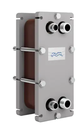
- Fouling, oil films or contamination on the fluid side reduce heat transfer and can cause abnormal approach temperatures
- Restricted strainers, poor refrigerant distribution or insufficient liquid flow causes unstable temperatures and reduced capacity
- Fatigue, corrosion or damage to the bonded plate pack can create internal leakage between circuits, detected by contamination, pressure behaviour or loss of charge
- External leakage at connections caused by vibration, thermal cycling or piping loads produces visible fluid loss or refrigerant alarms
- Freezing, liquid hammer or operation outside the approved pressure and temperature envelope can permanently damage the plate pack
- Fouling, oil films or contamination on the fluid side reduce heat transfer and can cause abnormal approach temperatures
- Restricted strainers, poor refrigerant distribution or insufficient liquid flow causes unstable temperatures and reduced capacity
- Fatigue, corrosion or damage to the bonded plate pack can create internal leakage between circuits, detected by contamination, pressure behaviour or loss of charge
- External leakage at connections caused by vibration, thermal cycling or piping loads produces visible fluid loss or refrigerant alarms
- Freezing, liquid hammer or operation outside the approved pressure and temperature envelope can permanently damage the plate pack
- Fouling, oil films or contamination on the fluid side reduce heat transfer and can cause abnormal approach temperatures
- Restricted strainers, poor refrigerant distribution or insufficient liquid flow causes unstable temperatures and reduced capacity
- Fatigue, corrosion or damage to the bonded plate pack can create internal leakage between circuits, detected by contamination, pressure behaviour or loss of charge
- External leakage at connections caused by vibration, thermal cycling or piping loads produces visible fluid loss or refrigerant alarms
- Freezing, liquid hammer or operation outside the approved pressure and temperature envelope can permanently damage the plate pack
- Fouling, oil films or contamination on the fluid side reduce heat transfer and can cause abnormal approach temperatures
- Restricted strainers, poor refrigerant distribution or insufficient liquid flow causes unstable temperatures and reduced capacity
- Fatigue, corrosion or damage to the bonded plate pack can create internal leakage between circuits, detected by contamination, pressure behaviour or loss of charge
- External leakage at connections caused by vibration, thermal cycling or piping loads produces visible fluid loss or refrigerant alarms
- Freezing, liquid hammer or operation outside the approved pressure and temperature envelope can permanently damage the plate pack
- Fouling, oil films or contamination on the fluid side reduce heat transfer and can cause abnormal approach temperatures
- Restricted strainers, poor refrigerant distribution or insufficient liquid flow causes unstable temperatures and reduced capacity
- Fatigue, corrosion or damage to the bonded plate pack can create internal leakage between circuits, detected by contamination, pressure behaviour or loss of charge
- External leakage at connections caused by vibration, thermal cycling or piping loads produces visible fluid loss or refrigerant alarms
- Freezing, liquid hammer or operation outside the approved pressure and temperature envelope can permanently damage the plate pack
- Fouling, oil films or contamination on the fluid side reduce heat transfer and can cause abnormal approach temperatures
- Restricted strainers, poor refrigerant distribution or insufficient liquid flow causes unstable temperatures and reduced capacity
- Fatigue, corrosion or damage to the bonded plate pack can create internal leakage between circuits, detected by contamination, pressure behaviour or loss of charge
- External leakage at connections caused by vibration, thermal cycling or piping loads produces visible fluid loss or refrigerant alarms
- Freezing, liquid hammer or operation outside the approved pressure and temperature envelope can permanently damage the plate pack
- Fouling, oil films or contamination on the fluid side reduce heat transfer and can cause abnormal approach temperatures
- Restricted strainers, poor refrigerant distribution or insufficient liquid flow causes unstable temperatures and reduced capacity
- Fatigue, corrosion or damage to the bonded plate pack can create internal leakage between circuits, detected by contamination, pressure behaviour or loss of charge
- External leakage at connections caused by vibration, thermal cycling or piping loads produces visible fluid loss or refrigerant alarms
- Freezing, liquid hammer or operation outside the approved pressure and temperature envelope can permanently damage the plate pack
- Fouling, oil films or contamination on the fluid side reduce heat transfer and can cause abnormal approach temperatures
- Restricted strainers, poor refrigerant distribution or insufficient liquid flow causes unstable temperatures and reduced capacity
- Fatigue, corrosion or damage to the bonded plate pack can create internal leakage between circuits, detected by contamination, pressure behaviour or loss of charge
- External leakage at connections caused by vibration, thermal cycling or piping loads produces visible fluid loss or refrigerant alarms
- Freezing, liquid hammer or operation outside the approved pressure and temperature envelope can permanently damage the plate pack
- Fouling, oil films or contamination on the fluid side reduce heat transfer and can cause abnormal approach temperatures
- Restricted strainers, poor refrigerant distribution or insufficient liquid flow causes unstable temperatures and reduced capacity
- Fatigue, corrosion or damage to the bonded plate pack can create internal leakage between circuits, detected by contamination, pressure behaviour or loss of charge
- External leakage at connections caused by vibration, thermal cycling or piping loads produces visible fluid loss or refrigerant alarms
- Freezing, liquid hammer or operation outside the approved pressure and temperature envelope can permanently damage the plate pack
- Fouling, oil films or contamination on the fluid side reduce heat transfer and can cause abnormal approach temperatures
- Restricted strainers, poor refrigerant distribution or insufficient liquid flow causes unstable temperatures and reduced capacity
- Fatigue, corrosion or damage to the bonded plate pack can create internal leakage between circuits, detected by contamination, pressure behaviour or loss of charge
- External leakage at connections caused by vibration, thermal cycling or piping loads produces visible fluid loss or refrigerant alarms
- Freezing, liquid hammer or operation outside the approved pressure and temperature envelope can permanently damage the plate pack
- Fouling, oil films or contamination on the fluid side reduce heat transfer and can cause abnormal approach temperatures
- Restricted strainers, poor refrigerant distribution or insufficient liquid flow causes unstable temperatures and reduced capacity
- Fatigue, corrosion or damage to the bonded plate pack can create internal leakage between circuits, detected by contamination, pressure behaviour or loss of charge
- External leakage at connections caused by vibration, thermal cycling or piping loads produces visible fluid loss or refrigerant alarms
- Freezing, liquid hammer or operation outside the approved pressure and temperature envelope can permanently damage the plate pack
- Fouling, oil films or contamination on the fluid side reduce heat transfer and can cause abnormal approach temperatures
- Restricted strainers, poor refrigerant distribution or insufficient liquid flow causes unstable temperatures and reduced capacity
- Fatigue, corrosion or damage to the bonded plate pack can create internal leakage between circuits, detected by contamination, pressure behaviour or loss of charge
- External leakage at connections caused by vibration, thermal cycling or piping loads produces visible fluid loss or refrigerant alarms
- Freezing, liquid hammer or operation outside the approved pressure and temperature envelope can permanently damage the plate pack
- Fouling, oil films or contamination on the fluid side reduce heat transfer and can cause abnormal approach temperatures
- Restricted strainers, poor refrigerant distribution or insufficient liquid flow causes unstable temperatures and reduced capacity
- Fatigue, corrosion or damage to the bonded plate pack can create internal leakage between circuits, detected by contamination, pressure behaviour or loss of charge
- External leakage at connections caused by vibration, thermal cycling or piping loads produces visible fluid loss or refrigerant alarms
- Freezing, liquid hammer or operation outside the approved pressure and temperature envelope can permanently damage the plate pack
- Fouling, oil films or contamination on the fluid side reduce heat transfer and can cause abnormal approach temperatures
- Restricted strainers, poor refrigerant distribution or insufficient liquid flow causes unstable temperatures and reduced capacity
- Fatigue, corrosion or damage to the bonded plate pack can create internal leakage between circuits, detected by contamination, pressure behaviour or loss of charge
- External leakage at connections caused by vibration, thermal cycling or piping loads produces visible fluid loss or refrigerant alarms
- Freezing, liquid hammer or operation outside the approved pressure and temperature envelope can permanently damage the plate pack
- Fouling, oil films or contamination on the fluid side reduce heat transfer and can cause abnormal approach temperatures
- Restricted strainers, poor refrigerant distribution or insufficient liquid flow causes unstable temperatures and reduced capacity
- Fatigue, corrosion or damage to the bonded plate pack can create internal leakage between circuits, detected by contamination, pressure behaviour or loss of charge
- External leakage at connections caused by vibration, thermal cycling or piping loads produces visible fluid loss or refrigerant alarms
- Freezing, liquid hammer or operation outside the approved pressure and temperature envelope can permanently damage the plate pack
- Fouling, oil films or contamination on the fluid side reduce heat transfer and can cause abnormal approach temperatures
- Restricted strainers, poor refrigerant distribution or insufficient liquid flow causes unstable temperatures and reduced capacity
- Fatigue, corrosion or damage to the bonded plate pack can create internal leakage between circuits, detected by contamination, pressure behaviour or loss of charge
- External leakage at connections caused by vibration, thermal cycling or piping loads produces visible fluid loss or refrigerant alarms
- Freezing, liquid hammer or operation outside the approved pressure and temperature envelope can permanently damage the plate pack
- Fouling, oil films or contamination on the fluid side reduce heat transfer and can cause abnormal approach temperatures
- Restricted strainers, poor refrigerant distribution or insufficient liquid flow causes unstable temperatures and reduced capacity
- Fatigue, corrosion or damage to the bonded plate pack can create internal leakage between circuits, detected by contamination, pressure behaviour or loss of charge
- External leakage at connections caused by vibration, thermal cycling or piping loads produces visible fluid loss or refrigerant alarms
- Freezing, liquid hammer or operation outside the approved pressure and temperature envelope can permanently damage the plate pack
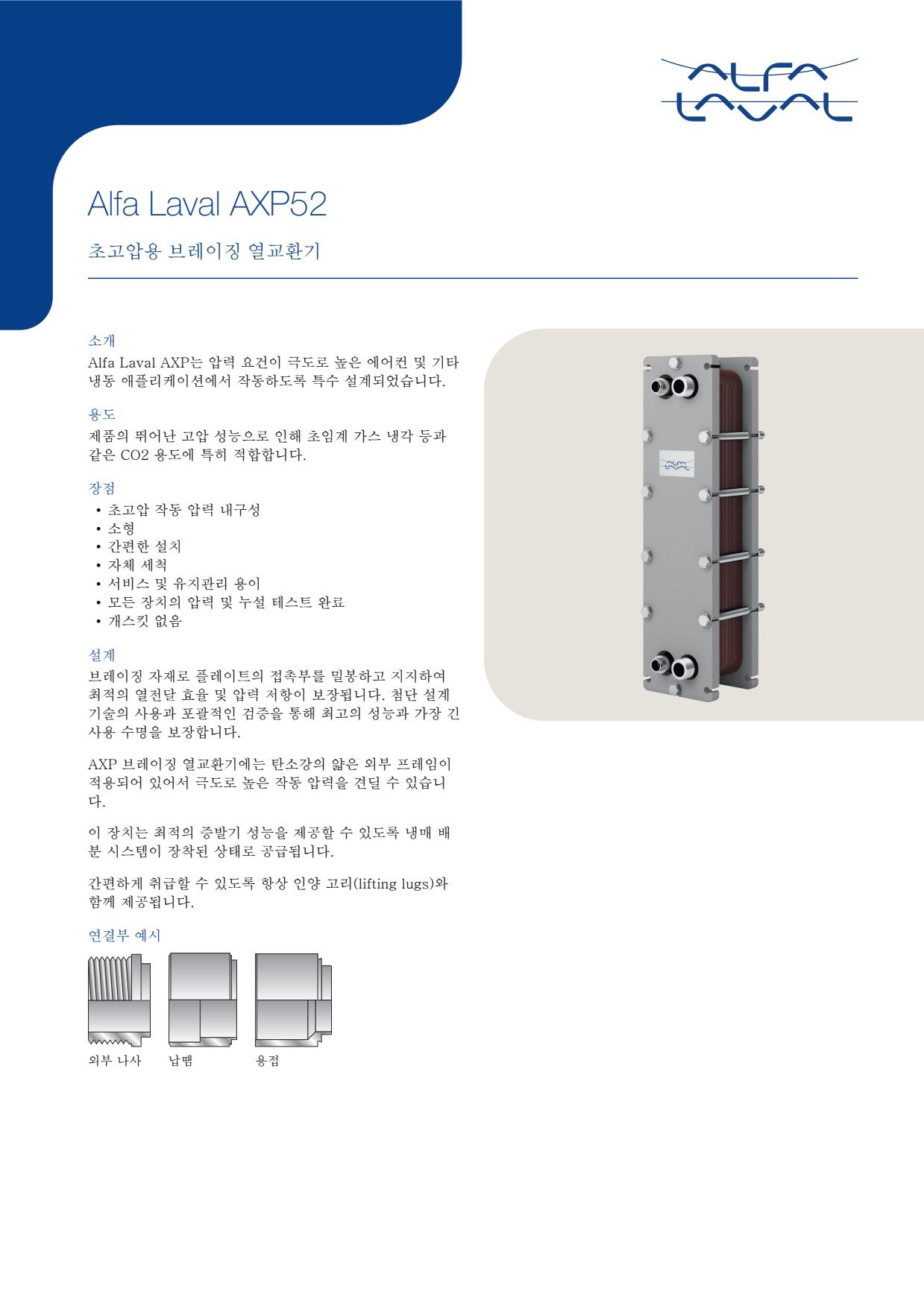
- Fouling, oil films or contamination on the fluid side reduce heat transfer and can cause abnormal approach temperatures
- Restricted strainers, poor refrigerant distribution or insufficient liquid flow causes unstable temperatures and reduced capacity
- Fatigue, corrosion or damage to the bonded plate pack can create internal leakage between circuits, detected by contamination, pressure behaviour or loss of charge
- External leakage at connections caused by vibration, thermal cycling or piping loads produces visible fluid loss or refrigerant alarms
- Freezing, liquid hammer or operation outside the approved pressure and temperature envelope can permanently damage the plate pack
- Fouling, oil films or contamination on the fluid side reduce heat transfer and can cause abnormal approach temperatures
- Restricted strainers, poor refrigerant distribution or insufficient liquid flow causes unstable temperatures and reduced capacity
- Fatigue, corrosion or damage to the bonded plate pack can create internal leakage between circuits, detected by contamination, pressure behaviour or loss of charge
- External leakage at connections caused by vibration, thermal cycling or piping loads produces visible fluid loss or refrigerant alarms
- Freezing, liquid hammer or operation outside the approved pressure and temperature envelope can permanently damage the plate pack
- Fouling, oil films or contamination on the fluid side reduce heat transfer and can cause abnormal approach temperatures
- Restricted strainers, poor refrigerant distribution or insufficient liquid flow causes unstable temperatures and reduced capacity
- Fatigue, corrosion or damage to the bonded plate pack can create internal leakage between circuits, detected by contamination, pressure behaviour or loss of charge
- External leakage at connections caused by vibration, thermal cycling or piping loads produces visible fluid loss or refrigerant alarms
- Freezing, liquid hammer or operation outside the approved pressure and temperature envelope can permanently damage the plate pack
- Fouling, oil films or contamination on the fluid side reduce heat transfer and can cause abnormal approach temperatures
- Restricted strainers, poor refrigerant distribution or insufficient liquid flow causes unstable temperatures and reduced capacity
- Fatigue, corrosion or damage to the bonded plate pack can create internal leakage between circuits, detected by contamination, pressure behaviour or loss of charge
- External leakage at connections caused by vibration, thermal cycling or piping loads produces visible fluid loss or refrigerant alarms
- Freezing, liquid hammer or operation outside the approved pressure and temperature envelope can permanently damage the plate pack
- Fouling or scaling inside the narrow plate channels reduces heat-transfer performance and increases pressure drop
- Blocked strainers or restricted upstream piping reduce flow and produce abnormal outlet temperatures
- Corrosion, erosion or fatigue damage to the bonded plate pack can cause internal cross-contamination between circuits
- External leakage at connections caused by damaged joints, vibration or piping loads produces visible fluid loss
- Freezing, thermal shock or operation outside the approved pressure and temperature envelope can damage the plate pack and lead to leakage
- Fouling or scaling inside the narrow plate channels reduces heat-transfer performance and increases pressure drop
- Blocked strainers or restricted upstream piping reduce flow and produce abnormal outlet temperatures
- Corrosion, erosion or fatigue damage to the bonded plate pack can cause internal cross-contamination between circuits
- External leakage at connections caused by damaged joints, vibration or piping loads produces visible fluid loss
- Freezing, thermal shock or operation outside the approved pressure and temperature envelope can damage the plate pack and lead to leakage
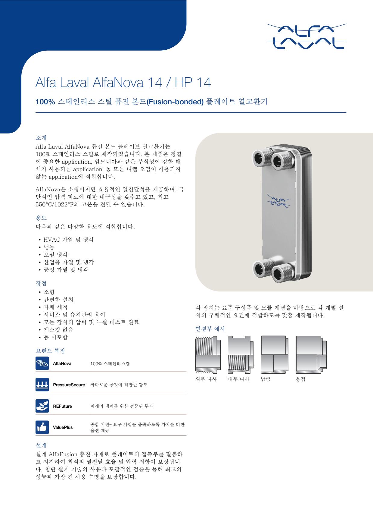
- Fouling or scaling inside the narrow plate channels reduces heat-transfer performance and increases pressure drop
- Blocked strainers or restricted upstream piping reduce flow and produce abnormal outlet temperatures
- Corrosion, erosion or fatigue damage to the bonded plate pack can cause internal cross-contamination between circuits
- External leakage at connections caused by damaged joints, vibration or piping loads produces visible fluid loss
- Freezing, thermal shock or operation outside the approved pressure and temperature envelope can damage the plate pack and lead to leakage
- Fouling or scaling inside the narrow plate channels reduces heat-transfer performance and increases pressure drop
- Blocked strainers or restricted upstream piping reduce flow and produce abnormal outlet temperatures
- Corrosion, erosion or fatigue damage to the bonded plate pack can cause internal cross-contamination between circuits
- External leakage at connections caused by damaged joints, vibration or piping loads produces visible fluid loss
- Freezing, thermal shock or operation outside the approved pressure and temperature envelope can damage the plate pack and lead to leakage
- Fouling or scaling inside the narrow plate channels reduces heat-transfer performance and increases pressure drop
- Blocked strainers or restricted upstream piping reduce flow and produce abnormal outlet temperatures
- Corrosion, erosion or fatigue damage to the bonded plate pack can cause internal cross-contamination between circuits
- External leakage at connections caused by damaged joints, vibration or piping loads produces visible fluid loss
- Freezing, thermal shock or operation outside the approved pressure and temperature envelope can damage the plate pack and lead to leakage
- Fouling or scaling inside the narrow plate channels reduces heat-transfer performance and increases pressure drop
- Blocked strainers or restricted upstream piping reduce flow and produce abnormal outlet temperatures
- Corrosion, erosion or fatigue damage to the bonded plate pack can cause internal cross-contamination between circuits
- External leakage at connections caused by damaged joints, vibration or piping loads produces visible fluid loss
- Freezing, thermal shock or operation outside the approved pressure and temperature envelope can damage the plate pack and lead to leakage
- Fouling or scaling inside the narrow plate channels reduces heat-transfer performance and increases pressure drop
- Blocked strainers or restricted upstream piping reduce flow and produce abnormal outlet temperatures
- Corrosion, erosion or fatigue damage to the bonded plate pack can cause internal cross-contamination between circuits
- External leakage at connections caused by damaged joints, vibration or piping loads produces visible fluid loss
- Freezing, thermal shock or operation outside the approved pressure and temperature envelope can damage the plate pack and lead to leakage
- Fouling or scaling inside the narrow plate channels reduces heat-transfer performance and increases pressure drop
- Blocked strainers or restricted upstream piping reduce flow and produce abnormal outlet temperatures
- Corrosion, erosion or fatigue damage to the bonded plate pack can cause internal cross-contamination between circuits
- External leakage at connections caused by damaged joints, vibration or piping loads produces visible fluid loss
- Freezing, thermal shock or operation outside the approved pressure and temperature envelope can damage the plate pack and lead to leakage
- Fouling or scaling inside the narrow plate channels reduces heat-transfer performance and increases pressure drop
- Blocked strainers or restricted upstream piping reduce flow and produce abnormal outlet temperatures
- Corrosion, erosion or fatigue damage to the bonded plate pack can cause internal cross-contamination between circuits
- External leakage at connections caused by damaged joints, vibration or piping loads produces visible fluid loss
- Freezing, thermal shock or operation outside the approved pressure and temperature envelope can damage the plate pack and lead to leakage
- Fouling or scaling inside the narrow plate channels reduces heat-transfer performance and increases pressure drop
- Blocked strainers or restricted upstream piping reduce flow and produce abnormal outlet temperatures
- Corrosion, erosion or fatigue damage to the bonded plate pack can cause internal cross-contamination between circuits
- External leakage at connections caused by damaged joints, vibration or piping loads produces visible fluid loss
- Freezing, thermal shock or operation outside the approved pressure and temperature envelope can damage the plate pack and lead to leakage
- Fouling or scaling inside the narrow plate channels reduces heat-transfer performance and increases pressure drop
- Blocked strainers or restricted upstream piping reduce flow and produce abnormal outlet temperatures
- Corrosion, erosion or fatigue damage to the bonded plate pack can cause internal cross-contamination between circuits
- External leakage at connections caused by damaged joints, vibration or piping loads produces visible fluid loss
- Freezing, thermal shock or operation outside the approved pressure and temperature envelope can damage the plate pack and lead to leakage
- Fouling or scaling inside the narrow plate channels reduces heat-transfer performance and increases pressure drop
- Blocked strainers or restricted upstream piping reduce flow and produce abnormal outlet temperatures
- Corrosion, erosion or fatigue damage to the bonded plate pack can cause internal cross-contamination between circuits
- External leakage at connections caused by damaged joints, vibration or piping loads produces visible fluid loss
- Freezing, thermal shock or operation outside the approved pressure and temperature envelope can damage the plate pack and lead to leakage
- Fouling or scaling inside the narrow plate channels reduces heat-transfer performance and increases pressure drop
- Blocked strainers or restricted upstream piping reduce flow and produce abnormal outlet temperatures
- Corrosion, erosion or fatigue damage to the bonded plate pack can cause internal cross-contamination between circuits
- External leakage at connections caused by damaged joints, vibration or piping loads produces visible fluid loss
- Freezing, thermal shock or operation outside the approved pressure and temperature envelope can damage the plate pack and lead to leakage
- Fouling or scaling inside the narrow plate channels reduces heat-transfer performance and increases pressure drop
- Blocked strainers or restricted upstream piping reduce flow and produce abnormal outlet temperatures
- Corrosion, erosion or fatigue damage to the bonded plate pack can cause internal cross-contamination between circuits
- External leakage at connections caused by damaged joints, vibration or piping loads produces visible fluid loss
- Freezing, thermal shock or operation outside the approved pressure and temperature envelope can damage the plate pack and lead to leakage
- Fouling or scaling inside the narrow plate channels reduces heat-transfer performance and increases pressure drop
- Blocked strainers or restricted upstream piping reduce flow and produce abnormal outlet temperatures
- Corrosion, erosion or fatigue damage to the bonded plate pack can cause internal cross-contamination between circuits
- External leakage at connections caused by damaged joints, vibration or piping loads produces visible fluid loss
- Freezing, thermal shock or operation outside the approved pressure and temperature envelope can damage the plate pack and lead to leakage
- Fouling or scaling inside the narrow plate channels reduces heat-transfer performance and increases pressure drop
- Blocked strainers or restricted upstream piping reduce flow and produce abnormal outlet temperatures
- Corrosion, erosion or fatigue damage to the bonded plate pack can cause internal cross-contamination between circuits
- External leakage at connections caused by damaged joints, vibration or piping loads produces visible fluid loss
- Freezing, thermal shock or operation outside the approved pressure and temperature envelope can damage the plate pack and lead to leakage
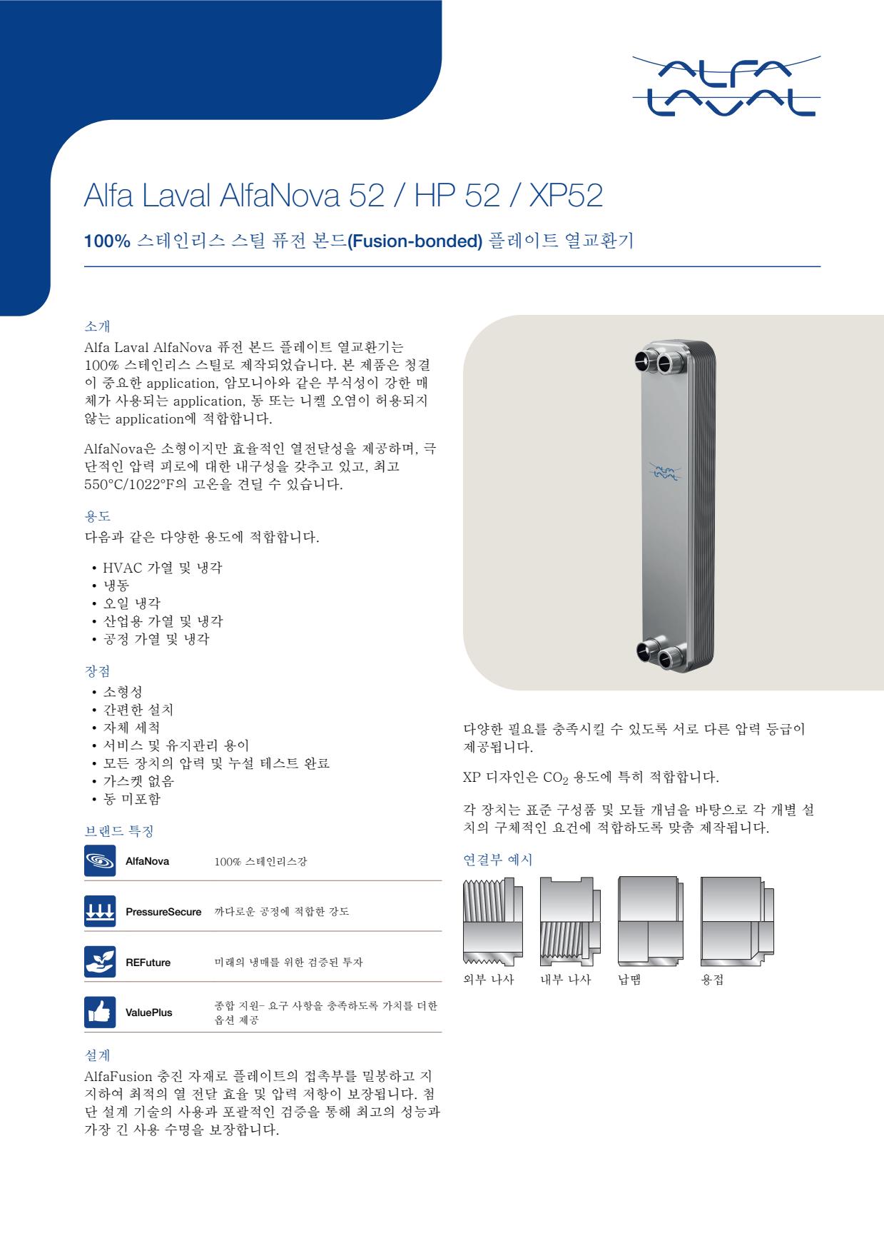
- Fouling or scaling inside the narrow plate channels reduces heat-transfer performance and increases pressure drop
- Blocked strainers or restricted upstream piping reduce flow and produce abnormal outlet temperatures
- Corrosion, erosion or fatigue damage to the bonded plate pack can cause internal cross-contamination between circuits
- External leakage at connections caused by damaged joints, vibration or piping loads produces visible fluid loss
- Freezing, thermal shock or operation outside the approved pressure and temperature envelope can damage the plate pack and lead to leakage
- Fouling or scaling inside the narrow plate channels reduces heat-transfer performance and increases pressure drop
- Blocked strainers or restricted upstream piping reduce flow and produce abnormal outlet temperatures
- Corrosion, erosion or fatigue damage to the bonded plate pack can cause internal cross-contamination between circuits
- External leakage at connections caused by damaged joints, vibration or piping loads produces visible fluid loss
- Freezing, thermal shock or operation outside the approved pressure and temperature envelope can damage the plate pack and lead to leakage
- Fouling or scaling inside the narrow plate channels reduces heat-transfer performance and increases pressure drop
- Blocked strainers or restricted upstream piping reduce flow and produce abnormal outlet temperatures
- Corrosion, erosion or fatigue damage to the bonded plate pack can cause internal cross-contamination between circuits
- External leakage at connections caused by damaged joints, vibration or piping loads produces visible fluid loss
- Freezing, thermal shock or operation outside the approved pressure and temperature envelope can damage the plate pack and lead to leakage
- Fouling or scaling inside the narrow plate channels reduces heat-transfer performance and increases pressure drop
- Blocked strainers or restricted upstream piping reduce flow and produce abnormal outlet temperatures
- Corrosion, erosion or fatigue damage to the bonded plate pack can cause internal cross-contamination between circuits
- External leakage at connections caused by damaged joints, vibration or piping loads produces visible fluid loss
- Freezing, thermal shock or operation outside the approved pressure and temperature envelope can damage the plate pack and lead to leakage
- Fouling or scaling inside narrow plate channels can increase pressure drop and reduce heat transfer
- Corrosion, erosion or fatigue damage can create internal leakage between circuits, indicated by cross-contamination or unexplained changes in fluid condition
- External connection leakage caused by damaged joints or piping loads can produce visible fluid loss
- Freezing, thermal shock or operation outside the approved envelope can damage the plate pack and cause leakage
- Blocked strainers or inadequate circulation can reduce flow and produce abnormal outlet temperatures
- Fouling or scaling inside narrow plate channels can increase pressure drop and reduce heat transfer
- Corrosion, erosion or fatigue damage can create internal leakage between circuits, indicated by cross-contamination or unexplained changes in fluid condition
- External connection leakage caused by damaged joints or piping loads can produce visible fluid loss
- Freezing, thermal shock or operation outside the approved envelope can damage the plate pack and cause leakage
- Blocked strainers or inadequate circulation can reduce flow and produce abnormal outlet temperatures
- Fouling or scaling inside narrow plate channels can increase pressure drop and reduce heat transfer
- Corrosion, erosion or fatigue damage can create internal leakage between circuits, indicated by cross-contamination or unexplained changes in fluid condition
- External connection leakage caused by damaged joints or piping loads can produce visible fluid loss
- Freezing, thermal shock or operation outside the approved envelope can damage the plate pack and cause leakage
- Blocked strainers or inadequate circulation can reduce flow and produce abnormal outlet temperatures
- Fouling or scaling inside narrow plate channels can increase pressure drop and reduce heat transfer
- Corrosion, erosion or fatigue damage can create internal leakage between circuits, indicated by cross-contamination or unexplained changes in fluid condition
- External connection leakage caused by damaged joints or piping loads can produce visible fluid loss
- Freezing, thermal shock or operation outside the approved envelope can damage the plate pack and cause leakage
- Blocked strainers or inadequate circulation can reduce flow and produce abnormal outlet temperatures
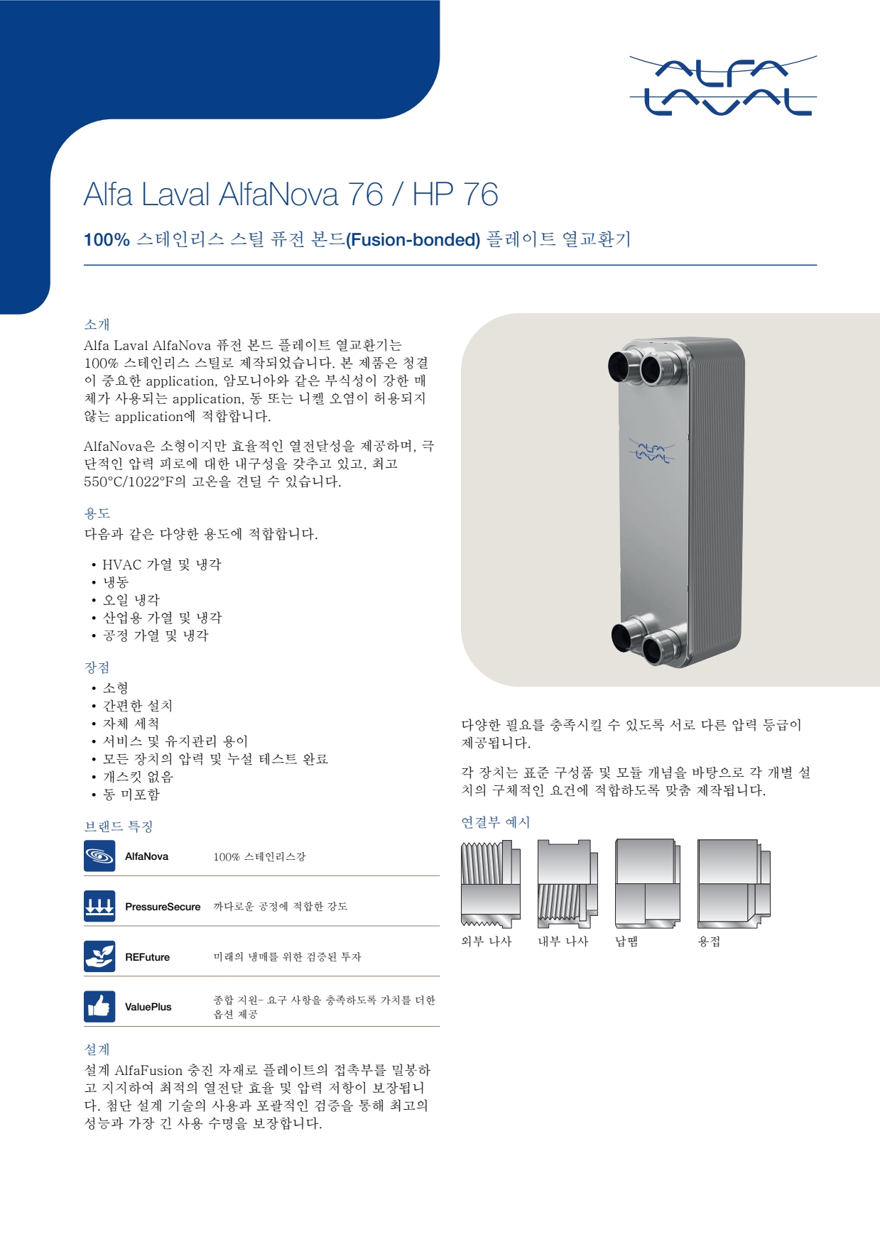
- Fouling or scaling inside narrow plate channels can increase pressure drop and reduce heat transfer
- Corrosion, erosion or fatigue damage can create internal leakage between circuits, indicated by cross-contamination or unexplained changes in fluid condition
- External connection leakage caused by damaged joints or piping loads can produce visible fluid loss
- Freezing, thermal shock or operation outside the approved envelope can damage the plate pack and cause leakage
- Blocked strainers or inadequate circulation can reduce flow and produce abnormal outlet temperatures
- Fouling or scaling inside narrow plate channels can increase pressure drop and reduce heat transfer
- Corrosion, erosion or fatigue damage can create internal leakage between circuits, indicated by cross-contamination or unexplained changes in fluid condition
- External connection leakage caused by damaged joints or piping loads can produce visible fluid loss
- Freezing, thermal shock or operation outside the approved envelope can damage the plate pack and cause leakage
- Blocked strainers or inadequate circulation can reduce flow and produce abnormal outlet temperatures
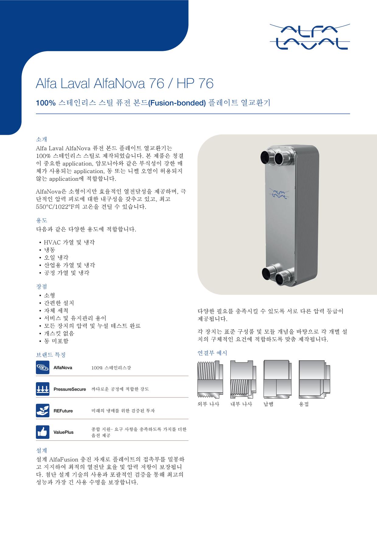
- Fouling or scaling inside narrow plate channels can increase pressure drop and reduce heat transfer
- Corrosion, erosion or fatigue damage can create internal leakage between circuits, indicated by cross-contamination or unexplained changes in fluid condition
- External connection leakage caused by damaged joints or piping loads can produce visible fluid loss
- Freezing, thermal shock or operation outside the approved envelope can damage the plate pack and cause leakage
- Blocked strainers or inadequate circulation can reduce flow and produce abnormal outlet temperatures
- Fouling or scaling inside narrow plate channels can increase pressure drop and reduce heat transfer
- Corrosion, erosion or fatigue damage can create internal leakage between circuits, indicated by cross-contamination or unexplained changes in fluid condition
- External connection leakage caused by damaged joints or piping loads can produce visible fluid loss
- Freezing, thermal shock or operation outside the approved envelope can damage the plate pack and cause leakage
- Blocked strainers or inadequate circulation can reduce flow and produce abnormal outlet temperatures
- Fouling or scaling inside narrow plate channels can increase pressure drop and reduce heat transfer
- Corrosion, erosion or fatigue damage can create internal leakage between circuits, indicated by cross-contamination or unexplained changes in fluid condition
- External connection leakage caused by damaged joints or piping loads can produce visible fluid loss
- Freezing, thermal shock or operation outside the approved envelope can damage the plate pack and cause leakage
- Blocked strainers or inadequate circulation can reduce flow and produce abnormal outlet temperatures
- Fouling or scaling inside narrow plate channels can increase pressure drop and reduce heat transfer
- Corrosion, erosion or fatigue damage can create internal leakage between circuits, indicated by cross-contamination or unexplained changes in fluid condition
- External connection leakage caused by damaged joints or piping loads can produce visible fluid loss
- Freezing, thermal shock or operation outside the approved envelope can damage the plate pack and cause leakage
- Blocked strainers or inadequate circulation can reduce flow and produce abnormal outlet temperatures
- Fouling or scaling inside narrow plate channels can increase pressure drop and reduce heat transfer
- Corrosion, erosion or fatigue damage can create internal leakage between circuits, indicated by cross-contamination or unexplained changes in fluid condition
- External connection leakage caused by damaged joints or piping loads can produce visible fluid loss
- Freezing, thermal shock or operation outside the approved envelope can damage the plate pack and cause leakage
- Blocked strainers or inadequate circulation can reduce flow and produce abnormal outlet temperatures
- Fouling or scaling inside narrow plate channels can increase pressure drop and reduce heat transfer
- Corrosion, erosion or fatigue damage can create internal leakage between circuits, indicated by cross-contamination or unexplained changes in fluid condition
- External connection leakage caused by damaged joints or piping loads can produce visible fluid loss
- Freezing, thermal shock or operation outside the approved envelope can damage the plate pack and cause leakage
- Blocked strainers or inadequate circulation can reduce flow and produce abnormal outlet temperatures
- Plate-channel fouling or scaling caused by contaminated fluid can increase pressure drop and reduce heat-transfer performance
- Aged, damaged or incorrectly seated gaskets can cause external leakage or mixing at the plate edge
- Corrosion, erosion or cracking of a plate can cause internal cross-contamination indicated by unexpected fluid quality, tank level or pressure changes
- Incorrect plate sequence or uneven tightening after maintenance can cause leakage, poor flow distribution or reduced thermal performance
- Blocked strainers or restricted upstream piping can reduce flow and produce abnormal inlet-to-outlet temperatures
- Plate-channel fouling or scaling caused by contaminated fluid can increase pressure drop and reduce heat-transfer performance
- Aged, damaged or incorrectly seated gaskets can cause external leakage or mixing at the plate edge
- Corrosion, erosion or cracking of a plate can cause internal cross-contamination indicated by unexpected fluid quality, tank level or pressure changes
- Incorrect plate sequence or uneven tightening after maintenance can cause leakage, poor flow distribution or reduced thermal performance
- Blocked strainers or restricted upstream piping can reduce flow and produce abnormal inlet-to-outlet temperatures
- Plate-channel fouling or scaling caused by contaminated fluid can increase pressure drop and reduce heat-transfer performance
- Aged, damaged or incorrectly seated gaskets can cause external leakage or mixing at the plate edge
- Corrosion, erosion or cracking of a plate can cause internal cross-contamination indicated by unexpected fluid quality, tank level or pressure changes
- Incorrect plate sequence or uneven tightening after maintenance can cause leakage, poor flow distribution or reduced thermal performance
- Blocked strainers or restricted upstream piping can reduce flow and produce abnormal inlet-to-outlet temperatures
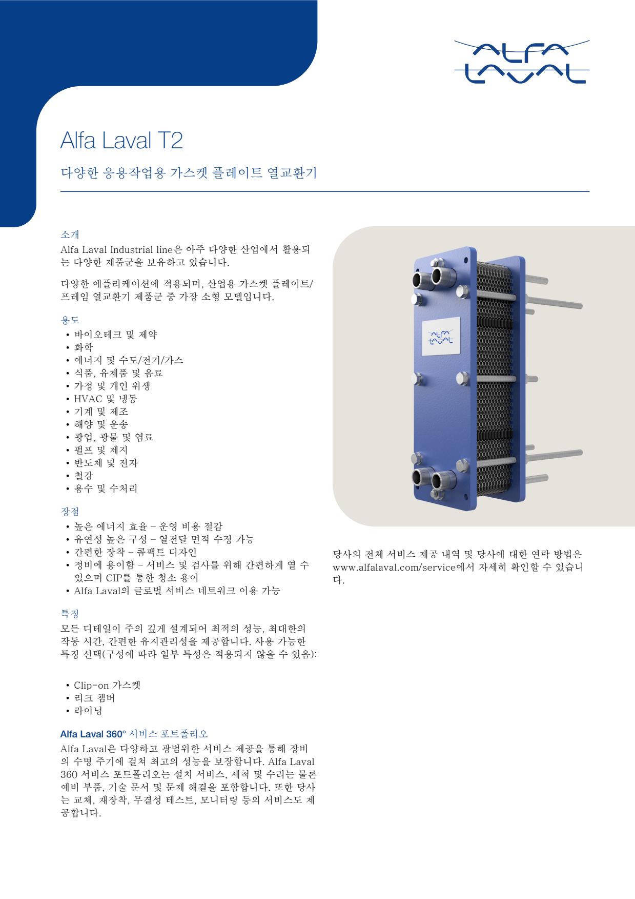
- Plate-channel fouling or scaling caused by contaminated fluid can increase pressure drop and reduce heat-transfer performance
- Aged, damaged or incorrectly seated gaskets can cause external leakage or mixing at the plate edge
- Corrosion, erosion or cracking of a plate can cause internal cross-contamination indicated by unexpected fluid quality, tank level or pressure changes
- Incorrect plate sequence or uneven tightening after maintenance can cause leakage, poor flow distribution or reduced thermal performance
- Blocked strainers or restricted upstream piping can reduce flow and produce abnormal inlet-to-outlet temperatures
- Plate-channel fouling or scaling caused by contaminated fluid can increase pressure drop and reduce heat-transfer performance
- Aged, damaged or incorrectly seated gaskets can cause external leakage or mixing at the plate edge
- Corrosion, erosion or cracking of a plate can cause internal cross-contamination indicated by unexpected fluid quality, tank level or pressure changes
- Incorrect plate sequence or uneven tightening after maintenance can cause leakage, poor flow distribution or reduced thermal performance
- Blocked strainers or restricted upstream piping can reduce flow and produce abnormal inlet-to-outlet temperatures
- Plate-channel fouling or scaling caused by contaminated fluid can increase pressure drop and reduce heat-transfer performance
- Aged, damaged or incorrectly seated gaskets can cause external leakage or mixing at the plate edge
- Corrosion, erosion or cracking of a plate can cause internal cross-contamination indicated by unexpected fluid quality, tank level or pressure changes
- Incorrect plate sequence or uneven tightening after maintenance can cause leakage, poor flow distribution or reduced thermal performance
- Blocked strainers or restricted upstream piping can reduce flow and produce abnormal inlet-to-outlet temperatures
-facing-right_medium.webp)
- Plate-channel fouling or scaling caused by contaminated fluid can increase pressure drop and reduce heat-transfer performance
- Aged, damaged or incorrectly seated gaskets can cause external leakage or mixing at the plate edge
- Corrosion, erosion or cracking of a plate can cause internal cross-contamination indicated by unexpected fluid quality, tank level or pressure changes
- Incorrect plate sequence or uneven tightening after maintenance can cause leakage, poor flow distribution or reduced thermal performance
- Blocked strainers or restricted upstream piping can reduce flow and produce abnormal inlet-to-outlet temperatures
- Plate-channel fouling or scaling caused by contaminated fluid can increase pressure drop and reduce heat-transfer performance
- Aged, damaged or incorrectly seated gaskets can cause external leakage or mixing at the plate edge
- Corrosion, erosion or cracking of a plate can cause internal cross-contamination indicated by unexpected fluid quality, tank level or pressure changes
- Incorrect plate sequence or uneven tightening after maintenance can cause leakage, poor flow distribution or reduced thermal performance
- Blocked strainers or restricted upstream piping can reduce flow and produce abnormal inlet-to-outlet temperatures
- Plate-channel fouling or scaling caused by contaminated fluid can increase pressure drop and reduce heat-transfer performance
- Aged, damaged or incorrectly seated gaskets can cause external leakage or mixing at the plate edge
- Corrosion, erosion or cracking of a plate can cause internal cross-contamination indicated by unexpected fluid quality, tank level or pressure changes
- Incorrect plate sequence or uneven tightening after maintenance can cause leakage, poor flow distribution or reduced thermal performance
- Blocked strainers or restricted upstream piping can reduce flow and produce abnormal inlet-to-outlet temperatures
- Plate-channel fouling or scaling caused by contaminated fluid can increase pressure drop and reduce heat-transfer performance
- Aged, damaged or incorrectly seated gaskets can cause external leakage or mixing at the plate edge
- Corrosion, erosion or cracking of a plate can cause internal cross-contamination indicated by unexpected fluid quality, tank level or pressure changes
- Incorrect plate sequence or uneven tightening after maintenance can cause leakage, poor flow distribution or reduced thermal performance
- Blocked strainers or restricted upstream piping can reduce flow and produce abnormal inlet-to-outlet temperatures
- Plate-channel fouling or scaling caused by contaminated fluid can increase pressure drop and reduce heat-transfer performance
- Aged, damaged or incorrectly seated gaskets can cause external leakage or mixing at the plate edge
- Corrosion, erosion or cracking of a plate can cause internal cross-contamination indicated by unexpected fluid quality, tank level or pressure changes
- Incorrect plate sequence or uneven tightening after maintenance can cause leakage, poor flow distribution or reduced thermal performance
- Blocked strainers or restricted upstream piping can reduce flow and produce abnormal inlet-to-outlet temperatures
- Plate-channel fouling or scaling caused by contaminated fluid can increase pressure drop and reduce heat-transfer performance
- Aged, damaged or incorrectly seated gaskets can cause external leakage or mixing at the plate edge
- Corrosion, erosion or cracking of a plate can cause internal cross-contamination indicated by unexpected fluid quality, tank level or pressure changes
- Incorrect plate sequence or uneven tightening after maintenance can cause leakage, poor flow distribution or reduced thermal performance
- Blocked strainers or restricted upstream piping can reduce flow and produce abnormal inlet-to-outlet temperatures
- Plate-channel fouling or scaling caused by contaminated fluid can increase pressure drop and reduce heat-transfer performance
- Aged, damaged or incorrectly seated gaskets can cause external leakage or mixing at the plate edge
- Corrosion, erosion or cracking of a plate can cause internal cross-contamination indicated by unexpected fluid quality, tank level or pressure changes
- Incorrect plate sequence or uneven tightening after maintenance can cause leakage, poor flow distribution or reduced thermal performance
- Blocked strainers or restricted upstream piping can reduce flow and produce abnormal inlet-to-outlet temperatures
- Plate-channel fouling or scaling caused by contaminated fluid can increase pressure drop and reduce heat-transfer performance
- Aged, damaged or incorrectly seated gaskets can cause external leakage or mixing at the plate edge
- Corrosion, erosion or cracking of a plate can cause internal cross-contamination indicated by unexpected fluid quality, tank level or pressure changes
- Incorrect plate sequence or uneven tightening after maintenance can cause leakage, poor flow distribution or reduced thermal performance
- Blocked strainers or restricted upstream piping can reduce flow and produce abnormal inlet-to-outlet temperatures
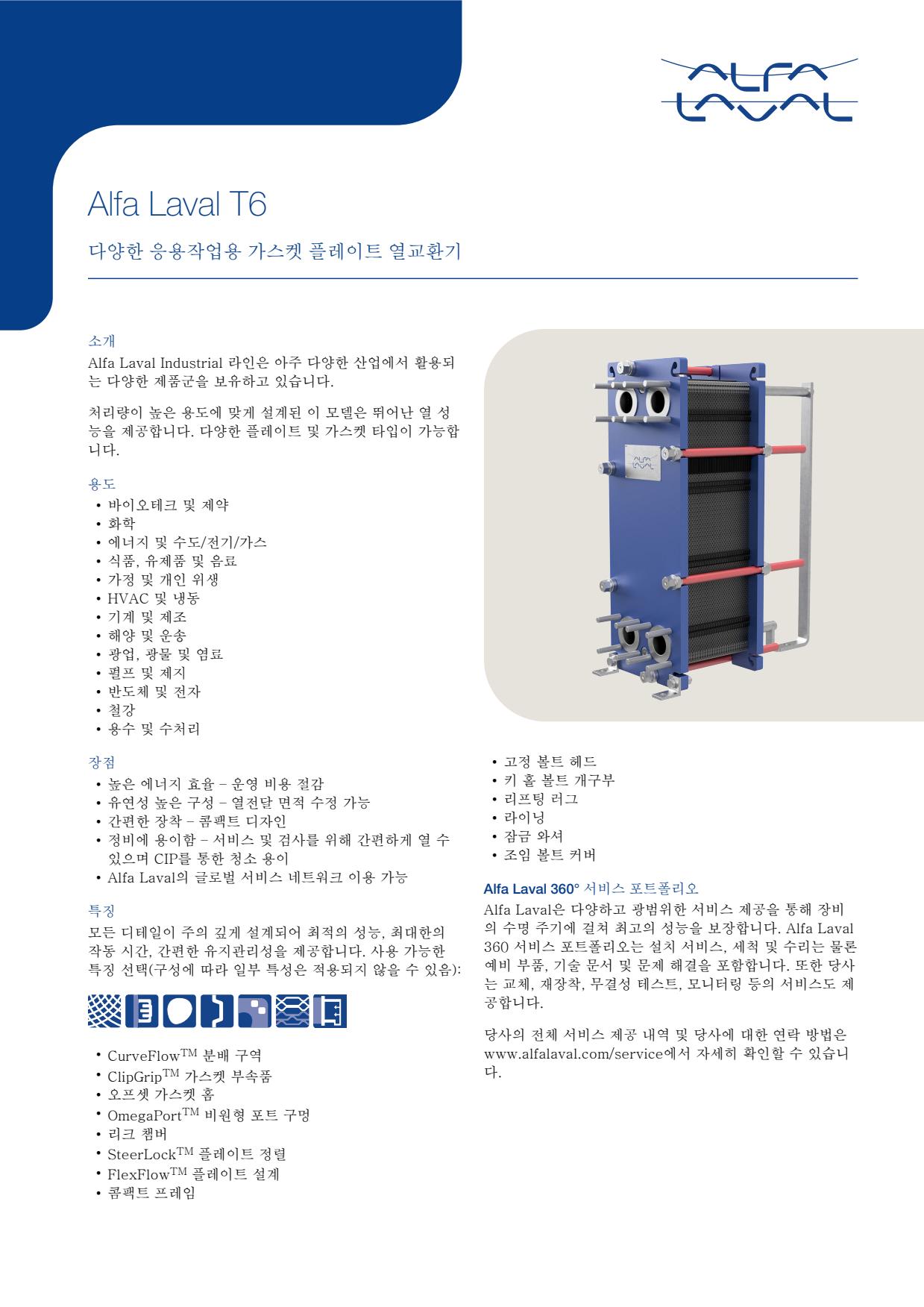
- Plate-channel fouling or scaling caused by contaminated fluid can increase pressure drop and reduce heat-transfer performance
- Aged, damaged or incorrectly seated gaskets can cause external leakage or mixing at the plate edge
- Corrosion, erosion or cracking of a plate can cause internal cross-contamination indicated by unexpected fluid quality, tank level or pressure changes
- Incorrect plate sequence or uneven tightening after maintenance can cause leakage, poor flow distribution or reduced thermal performance
- Blocked strainers or restricted upstream piping can reduce flow and produce abnormal inlet-to-outlet temperatures
-facing-left_medium.webp)
- Plate-channel fouling or scaling caused by contaminated fluid can increase pressure drop and reduce heat-transfer performance
- Aged, damaged or incorrectly seated gaskets can cause external leakage or mixing at the plate edge
- Corrosion, erosion or cracking of a plate can cause internal cross-contamination indicated by unexpected fluid quality, tank level or pressure changes
- Incorrect plate sequence or uneven tightening after maintenance can cause leakage, poor flow distribution or reduced thermal performance
- Blocked strainers or restricted upstream piping can reduce flow and produce abnormal inlet-to-outlet temperatures
- Plate-channel fouling or scaling caused by contaminated fluid can increase pressure drop and reduce heat-transfer performance
- Aged, damaged or incorrectly seated gaskets can cause external leakage or mixing at the plate edge
- Corrosion, erosion or cracking of a plate can cause internal cross-contamination indicated by unexpected fluid quality, tank level or pressure changes
- Incorrect plate sequence or uneven tightening after maintenance can cause leakage, poor flow distribution or reduced thermal performance
- Blocked strainers or restricted upstream piping can reduce flow and produce abnormal inlet-to-outlet temperatures
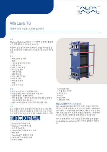
- Plate-channel fouling or scaling caused by contaminated fluid can increase pressure drop and reduce heat-transfer performance
- Aged, damaged or incorrectly seated gaskets can cause external leakage or mixing at the plate edge
- Corrosion, erosion or cracking of a plate can cause internal cross-contamination indicated by unexpected fluid quality, tank level or pressure changes
- Incorrect plate sequence or uneven tightening after maintenance can cause leakage, poor flow distribution or reduced thermal performance
- Blocked strainers or restricted upstream piping can reduce flow and produce abnormal inlet-to-outlet temperatures
- Plate-channel fouling or scaling caused by contaminated fluid can increase pressure drop and reduce heat-transfer performance
- Aged, damaged or incorrectly seated gaskets can cause external leakage or mixing at the plate edge
- Corrosion, erosion or cracking of a plate can cause internal cross-contamination indicated by unexpected fluid quality, tank level or pressure changes
- Incorrect plate sequence or uneven tightening after maintenance can cause leakage, poor flow distribution or reduced thermal performance
- Blocked strainers or restricted upstream piping can reduce flow and produce abnormal inlet-to-outlet temperatures
- Plate-channel fouling or scaling caused by contaminated fluid can increase pressure drop and reduce heat-transfer performance
- Aged, damaged or incorrectly seated gaskets can cause external leakage or mixing at the plate edge
- Corrosion, erosion or cracking of a plate can cause internal cross-contamination indicated by unexpected fluid quality, tank level or pressure changes
- Incorrect plate sequence or uneven tightening after maintenance can cause leakage, poor flow distribution or reduced thermal performance
- Blocked strainers or restricted upstream piping can reduce flow and produce abnormal inlet-to-outlet temperatures
-facing-right_medium.png)
- Plate-channel fouling or scaling caused by contaminated fluid can increase pressure drop and reduce heat-transfer performance
- Aged, damaged or incorrectly seated gaskets can cause external leakage or mixing at the plate edge
- Corrosion, erosion or cracking of a plate can cause internal cross-contamination indicated by unexpected fluid quality, tank level or pressure changes
- Incorrect plate sequence or uneven tightening after maintenance can cause leakage, poor flow distribution or reduced thermal performance
- Blocked strainers or restricted upstream piping can reduce flow and produce abnormal inlet-to-outlet temperatures
- Plate-channel fouling or scaling caused by contaminated fluid can increase pressure drop and reduce heat-transfer performance
- Aged, damaged or incorrectly seated gaskets can cause external leakage or mixing at the plate edge
- Corrosion, erosion or cracking of a plate can cause internal cross-contamination indicated by unexpected fluid quality, tank level or pressure changes
- Incorrect plate sequence or uneven tightening after maintenance can cause leakage, poor flow distribution or reduced thermal performance
- Blocked strainers or restricted upstream piping can reduce flow and produce abnormal inlet-to-outlet temperatures
- Plate-channel fouling or scaling caused by contaminated fluid can increase pressure drop and reduce heat-transfer performance
- Aged, damaged or incorrectly seated gaskets can cause external leakage or mixing at the plate edge
- Corrosion, erosion or cracking of a plate can cause internal cross-contamination indicated by unexpected fluid quality, tank level or pressure changes
- Incorrect plate sequence or uneven tightening after maintenance can cause leakage, poor flow distribution or reduced thermal performance
- Blocked strainers or restricted upstream piping can reduce flow and produce abnormal inlet-to-outlet temperatures
- Plate-channel fouling or scaling caused by contaminated fluid can increase pressure drop and reduce heat-transfer performance
- Aged, damaged or incorrectly seated gaskets can cause external leakage or mixing at the plate edge
- Corrosion, erosion or cracking of a plate can cause internal cross-contamination indicated by unexpected fluid quality, tank level or pressure changes
- Incorrect plate sequence or uneven tightening after maintenance can cause leakage, poor flow distribution or reduced thermal performance
- Blocked strainers or restricted upstream piping can reduce flow and produce abnormal inlet-to-outlet temperatures
- Plate-channel fouling or scaling caused by contaminated fluid can increase pressure drop and reduce heat-transfer performance
- Aged, damaged or incorrectly seated gaskets can cause external leakage or mixing at the plate edge
- Corrosion, erosion or cracking of a plate can cause internal cross-contamination indicated by unexpected fluid quality, tank level or pressure changes
- Incorrect plate sequence or uneven tightening after maintenance can cause leakage, poor flow distribution or reduced thermal performance
- Blocked strainers or restricted upstream piping can reduce flow and produce abnormal inlet-to-outlet temperatures
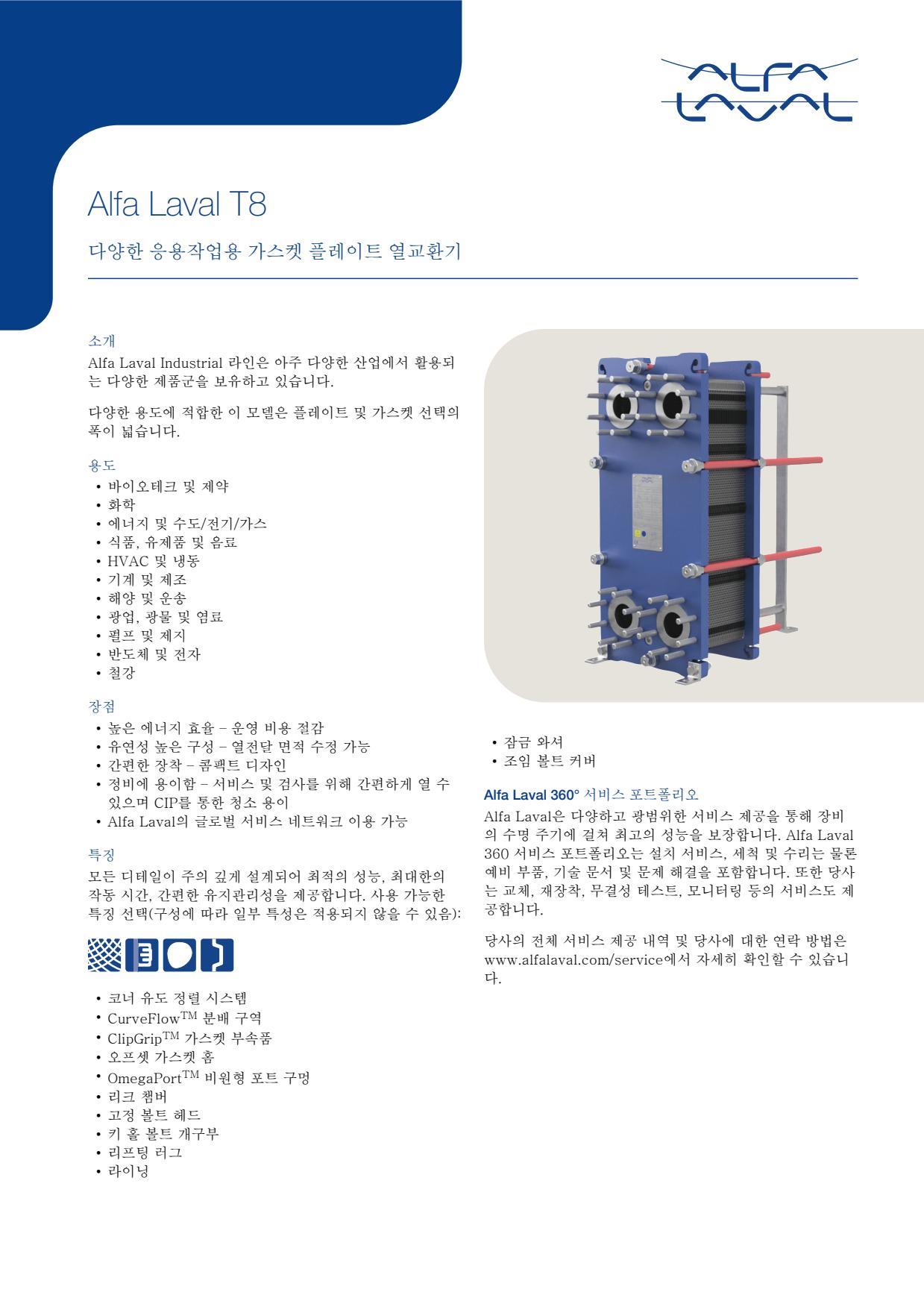
- Plate-channel fouling or scaling caused by contaminated fluid can increase pressure drop and reduce heat-transfer performance
- Aged, damaged or incorrectly seated gaskets can cause external leakage or mixing at the plate edge
- Corrosion, erosion or cracking of a plate can cause internal cross-contamination indicated by unexpected fluid quality, tank level or pressure changes
- Incorrect plate sequence or uneven tightening after maintenance can cause leakage, poor flow distribution or reduced thermal performance
- Blocked strainers or restricted upstream piping can reduce flow and produce abnormal inlet-to-outlet temperatures
- Plate-channel fouling or scaling caused by contaminated fluid can increase pressure drop and reduce heat-transfer performance
- Aged, damaged or incorrectly seated gaskets can cause external leakage or mixing at the plate edge
- Corrosion, erosion or cracking of a plate can cause internal cross-contamination indicated by unexpected fluid quality, tank level or pressure changes
- Incorrect plate sequence or uneven tightening after maintenance can cause leakage, poor flow distribution or reduced thermal performance
- Blocked strainers or restricted upstream piping can reduce flow and produce abnormal inlet-to-outlet temperatures
- Plate-channel fouling or scaling caused by contaminated fluid can increase pressure drop and reduce heat-transfer performance
- Aged, damaged or incorrectly seated gaskets can cause external leakage or mixing at the plate edge
- Corrosion, erosion or cracking of a plate can cause internal cross-contamination indicated by unexpected fluid quality, tank level or pressure changes
- Incorrect plate sequence or uneven tightening after maintenance can cause leakage, poor flow distribution or reduced thermal performance
- Blocked strainers or restricted upstream piping can reduce flow and produce abnormal inlet-to-outlet temperatures
- Plate-channel fouling or scaling caused by contaminated fluid can increase pressure drop and reduce heat-transfer performance
- Aged, damaged or incorrectly seated gaskets can cause external leakage or mixing at the plate edge
- Corrosion, erosion or cracking of a plate can cause internal cross-contamination indicated by unexpected fluid quality, tank level or pressure changes
- Incorrect plate sequence or uneven tightening after maintenance can cause leakage, poor flow distribution or reduced thermal performance
- Blocked strainers or restricted upstream piping can reduce flow and produce abnormal inlet-to-outlet temperatures
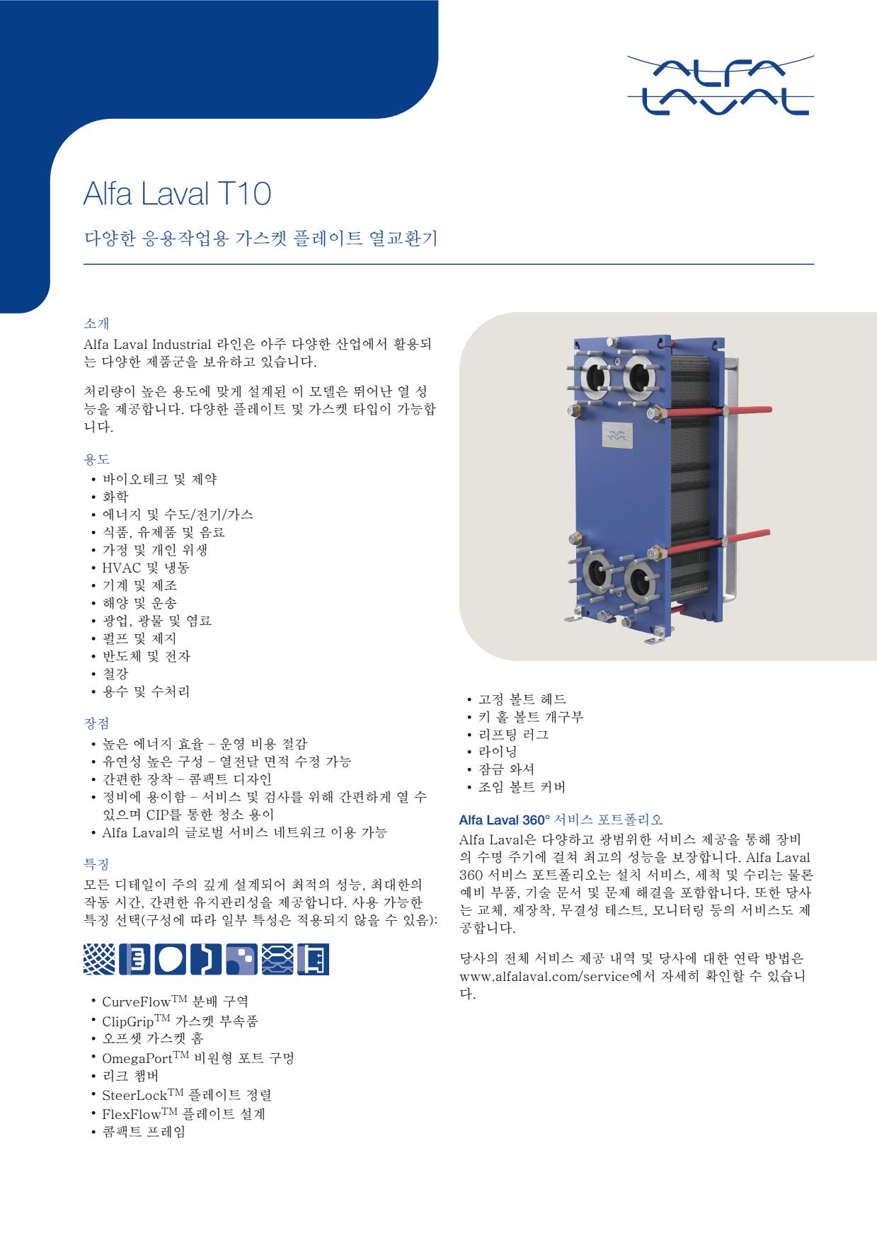
- Plate-channel fouling or scaling caused by contaminated fluid can increase pressure drop and reduce heat-transfer performance
- Aged, damaged or incorrectly seated gaskets can cause external leakage or mixing at the plate edge
- Corrosion, erosion or cracking of a plate can cause internal cross-contamination indicated by unexpected fluid quality, tank level or pressure changes
- Incorrect plate sequence or uneven tightening after maintenance can cause leakage, poor flow distribution or reduced thermal performance
- Blocked strainers or restricted upstream piping can reduce flow and produce abnormal inlet-to-outlet temperatures
- Plate-channel fouling or scaling caused by contaminated fluid can increase pressure drop and reduce heat-transfer performance
- Aged, damaged or incorrectly seated gaskets can cause external leakage or mixing at the plate edge
- Corrosion, erosion or cracking of a plate can cause internal cross-contamination indicated by unexpected fluid quality, tank level or pressure changes
- Incorrect plate sequence or uneven tightening after maintenance can cause leakage, poor flow distribution or reduced thermal performance
- Blocked strainers or restricted upstream piping can reduce flow and produce abnormal inlet-to-outlet temperatures
- Plate-channel fouling or scaling caused by contaminated fluid can increase pressure drop and reduce heat-transfer performance
- Aged, damaged or incorrectly seated gaskets can cause external leakage or mixing at the plate edge
- Corrosion, erosion or cracking of a plate can cause internal cross-contamination indicated by unexpected fluid quality, tank level or pressure changes
- Incorrect plate sequence or uneven tightening after maintenance can cause leakage, poor flow distribution or reduced thermal performance
- Blocked strainers or restricted upstream piping can reduce flow and produce abnormal inlet-to-outlet temperatures
- Plate-channel fouling or scaling caused by contaminated fluid can increase pressure drop and reduce heat-transfer performance
- Aged, damaged or incorrectly seated gaskets can cause external leakage or mixing at the plate edge
- Corrosion, erosion or cracking of a plate can cause internal cross-contamination indicated by unexpected fluid quality, tank level or pressure changes
- Incorrect plate sequence or uneven tightening after maintenance can cause leakage, poor flow distribution or reduced thermal performance
- Blocked strainers or restricted upstream piping can reduce flow and produce abnormal inlet-to-outlet temperatures
- Plate-channel fouling or scaling caused by contaminated fluid can increase pressure drop and reduce heat-transfer performance
- Aged, damaged or incorrectly seated gaskets can cause external leakage or mixing at the plate edge
- Corrosion, erosion or cracking of a plate can cause internal cross-contamination indicated by unexpected fluid quality, tank level or pressure changes
- Incorrect plate sequence or uneven tightening after maintenance can cause leakage, poor flow distribution or reduced thermal performance
- Blocked strainers or restricted upstream piping can reduce flow and produce abnormal inlet-to-outlet temperatures
- Plate-channel fouling or scaling caused by contaminated fluid can increase pressure drop and reduce heat-transfer performance
- Aged, damaged or incorrectly seated gaskets can cause external leakage or mixing at the plate edge
- Corrosion, erosion or cracking of a plate can cause internal cross-contamination indicated by unexpected fluid quality, tank level or pressure changes
- Incorrect plate sequence or uneven tightening after maintenance can cause leakage, poor flow distribution or reduced thermal performance
- Blocked strainers or restricted upstream piping can reduce flow and produce abnormal inlet-to-outlet temperatures
- Plate-channel fouling or scaling caused by contaminated fluid can increase pressure drop and reduce heat-transfer performance
- Aged, damaged or incorrectly seated gaskets can cause external leakage or mixing at the plate edge
- Corrosion, erosion or cracking of a plate can cause internal cross-contamination indicated by unexpected fluid quality, tank level or pressure changes
- Incorrect plate sequence or uneven tightening after maintenance can cause leakage, poor flow distribution or reduced thermal performance
- Blocked strainers or restricted upstream piping can reduce flow and produce abnormal inlet-to-outlet temperatures
- Plate-channel fouling or scaling caused by contaminated fluid can increase pressure drop and reduce heat-transfer performance
- Aged, damaged or incorrectly seated gaskets can cause external leakage or mixing at the plate edge
- Corrosion, erosion or cracking of a plate can cause internal cross-contamination indicated by unexpected fluid quality, tank level or pressure changes
- Incorrect plate sequence or uneven tightening after maintenance can cause leakage, poor flow distribution or reduced thermal performance
- Blocked strainers or restricted upstream piping can reduce flow and produce abnormal inlet-to-outlet temperatures
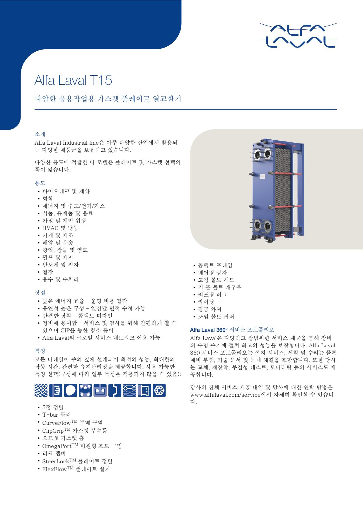
- Plate-channel fouling or scaling caused by contaminated fluid can increase pressure drop and reduce heat-transfer performance
- Aged, damaged or incorrectly seated gaskets can cause external leakage or mixing at the plate edge
- Corrosion, erosion or cracking of a plate can cause internal cross-contamination indicated by unexpected fluid quality, tank level or pressure changes
- Incorrect plate sequence or uneven tightening after maintenance can cause leakage, poor flow distribution or reduced thermal performance
- Blocked strainers or restricted upstream piping can reduce flow and produce abnormal inlet-to-outlet temperatures
- Plate-channel fouling or scaling caused by contaminated fluid can increase pressure drop and reduce heat-transfer performance
- Aged, damaged or incorrectly seated gaskets can cause external leakage or mixing at the plate edge
- Corrosion, erosion or cracking of a plate can cause internal cross-contamination indicated by unexpected fluid quality, tank level or pressure changes
- Incorrect plate sequence or uneven tightening after maintenance can cause leakage, poor flow distribution or reduced thermal performance
- Blocked strainers or restricted upstream piping can reduce flow and produce abnormal inlet-to-outlet temperatures
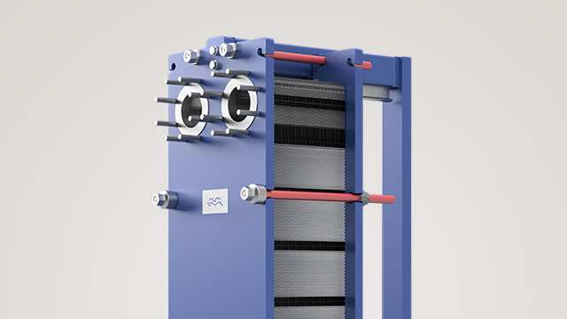
- Plate-channel fouling or scaling caused by contaminated fluid can increase pressure drop and reduce heat-transfer performance
- Aged, damaged or incorrectly seated gaskets can cause external leakage or mixing at the plate edge
- Corrosion, erosion or cracking of a plate can cause internal cross-contamination indicated by unexpected fluid quality, tank level or pressure changes
- Incorrect plate sequence or uneven tightening after maintenance can cause leakage, poor flow distribution or reduced thermal performance
- Blocked strainers or restricted upstream piping can reduce flow and produce abnormal inlet-to-outlet temperatures
- Plate-channel fouling or scaling caused by contaminated fluid can increase pressure drop and reduce heat-transfer performance
- Aged, damaged or incorrectly seated gaskets can cause external leakage or mixing at the plate edge
- Corrosion, erosion or cracking of a plate can cause internal cross-contamination indicated by unexpected fluid quality, tank level or pressure changes
- Incorrect plate sequence or uneven tightening after maintenance can cause leakage, poor flow distribution or reduced thermal performance
- Blocked strainers or restricted upstream piping can reduce flow and produce abnormal inlet-to-outlet temperatures
- Plate-channel fouling or scaling caused by contaminated fluid can increase pressure drop and reduce heat-transfer performance
- Aged, damaged or incorrectly seated gaskets can cause external leakage or mixing at the plate edge
- Corrosion, erosion or cracking of a plate can cause internal cross-contamination indicated by unexpected fluid quality, tank level or pressure changes
- Incorrect plate sequence or uneven tightening after maintenance can cause leakage, poor flow distribution or reduced thermal performance
- Blocked strainers or restricted upstream piping can reduce flow and produce abnormal inlet-to-outlet temperatures
- Plate-channel fouling or scaling caused by contaminated fluid can increase pressure drop and reduce heat-transfer performance
- Aged, damaged or incorrectly seated gaskets can cause external leakage or mixing at the plate edge
- Corrosion, erosion or cracking of a plate can cause internal cross-contamination indicated by unexpected fluid quality, tank level or pressure changes
- Incorrect plate sequence or uneven tightening after maintenance can cause leakage, poor flow distribution or reduced thermal performance
- Blocked strainers or restricted upstream piping can reduce flow and produce abnormal inlet-to-outlet temperatures
- Plate-channel fouling or scaling caused by contaminated fluid can increase pressure drop and reduce heat-transfer performance
- Aged, damaged or incorrectly seated gaskets can cause external leakage or mixing at the plate edge
- Corrosion, erosion or cracking of a plate can cause internal cross-contamination indicated by unexpected fluid quality, tank level or pressure changes
- Incorrect plate sequence or uneven tightening after maintenance can cause leakage, poor flow distribution or reduced thermal performance
- Blocked strainers or restricted upstream piping can reduce flow and produce abnormal inlet-to-outlet temperatures
- Plate-channel fouling or scaling caused by contaminated fluid can increase pressure drop and reduce heat-transfer performance
- Aged, damaged or incorrectly seated gaskets can cause external leakage or mixing at the plate edge
- Corrosion, erosion or cracking of a plate can cause internal cross-contamination indicated by unexpected fluid quality, tank level or pressure changes
- Incorrect plate sequence or uneven tightening after maintenance can cause leakage, poor flow distribution or reduced thermal performance
- Blocked strainers or restricted upstream piping can reduce flow and produce abnormal inlet-to-outlet temperatures
- Plate-channel fouling or scaling caused by contaminated fluid can increase pressure drop and reduce heat-transfer performance
- Aged, damaged or incorrectly seated gaskets can cause external leakage or mixing at the plate edge
- Corrosion, erosion or cracking of a plate can cause internal cross-contamination indicated by unexpected fluid quality, tank level or pressure changes
- Incorrect plate sequence or uneven tightening after maintenance can cause leakage, poor flow distribution or reduced thermal performance
- Blocked strainers or restricted upstream piping can reduce flow and produce abnormal inlet-to-outlet temperatures
- Plate-channel fouling or scaling caused by contaminated fluid can increase pressure drop and reduce heat-transfer performance
- Aged, damaged or incorrectly seated gaskets can cause external leakage or mixing at the plate edge
- Corrosion, erosion or cracking of a plate can cause internal cross-contamination indicated by unexpected fluid quality, tank level or pressure changes
- Incorrect plate sequence or uneven tightening after maintenance can cause leakage, poor flow distribution or reduced thermal performance
- Blocked strainers or restricted upstream piping can reduce flow and produce abnormal inlet-to-outlet temperatures
- Plate-channel fouling or scaling caused by contaminated fluid can increase pressure drop and reduce heat-transfer performance
- Aged, damaged or incorrectly seated gaskets can cause external leakage or mixing at the plate edge
- Corrosion, erosion or cracking of a plate can cause internal cross-contamination indicated by unexpected fluid quality, tank level or pressure changes
- Incorrect plate sequence or uneven tightening after maintenance can cause leakage, poor flow distribution or reduced thermal performance
- Blocked strainers or restricted upstream piping can reduce flow and produce abnormal inlet-to-outlet temperatures
- Plate-channel fouling or scaling caused by contaminated fluid can increase pressure drop and reduce heat-transfer performance
- Aged, damaged or incorrectly seated gaskets can cause external leakage or mixing at the plate edge
- Corrosion, erosion or cracking of a plate can cause internal cross-contamination indicated by unexpected fluid quality, tank level or pressure changes
- Incorrect plate sequence or uneven tightening after maintenance can cause leakage, poor flow distribution or reduced thermal performance
- Blocked strainers or restricted upstream piping can reduce flow and produce abnormal inlet-to-outlet temperatures
- Plate-channel fouling or scaling caused by contaminated fluid can increase pressure drop and reduce heat-transfer performance
- Aged, damaged or incorrectly seated gaskets can cause external leakage or mixing at the plate edge
- Corrosion, erosion or cracking of a plate can cause internal cross-contamination indicated by unexpected fluid quality, tank level or pressure changes
- Incorrect plate sequence or uneven tightening after maintenance can cause leakage, poor flow distribution or reduced thermal performance
- Blocked strainers or restricted upstream piping can reduce flow and produce abnormal inlet-to-outlet temperatures
- Plate-channel fouling or scaling caused by contaminated fluid can increase pressure drop and reduce heat-transfer performance
- Aged, damaged or incorrectly seated gaskets can cause external leakage or mixing at the plate edge
- Corrosion, erosion or cracking of a plate can cause internal cross-contamination indicated by unexpected fluid quality, tank level or pressure changes
- Incorrect plate sequence or uneven tightening after maintenance can cause leakage, poor flow distribution or reduced thermal performance
- Blocked strainers or restricted upstream piping can reduce flow and produce abnormal inlet-to-outlet temperatures
- Plate-channel fouling or scaling caused by contaminated fluid can increase pressure drop and reduce heat-transfer performance
- Aged, damaged or incorrectly seated gaskets can cause external leakage or mixing at the plate edge
- Corrosion, erosion or cracking of a plate can cause internal cross-contamination indicated by unexpected fluid quality, tank level or pressure changes
- Incorrect plate sequence or uneven tightening after maintenance can cause leakage, poor flow distribution or reduced thermal performance
- Blocked strainers or restricted upstream piping can reduce flow and produce abnormal inlet-to-outlet temperatures
- Plate-channel fouling or scaling caused by contaminated fluid can increase pressure drop and reduce heat-transfer performance
- Aged, damaged or incorrectly seated gaskets can cause external leakage or mixing at the plate edge
- Corrosion, erosion or cracking of a plate can cause internal cross-contamination indicated by unexpected fluid quality, tank level or pressure changes
- Incorrect plate sequence or uneven tightening after maintenance can cause leakage, poor flow distribution or reduced thermal performance
- Blocked strainers or restricted upstream piping can reduce flow and produce abnormal inlet-to-outlet temperatures
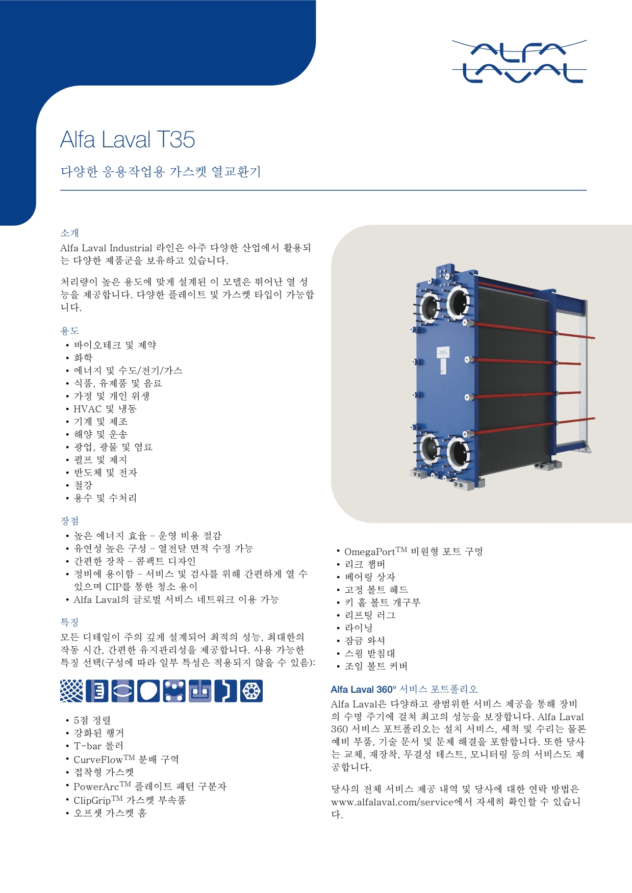
- Plate-channel fouling or scaling caused by contaminated fluid can increase pressure drop and reduce heat-transfer performance
- Aged, damaged or incorrectly seated gaskets can cause external leakage or mixing at the plate edge
- Corrosion, erosion or cracking of a plate can cause internal cross-contamination indicated by unexpected fluid quality, tank level or pressure changes
- Incorrect plate sequence or uneven tightening after maintenance can cause leakage, poor flow distribution or reduced thermal performance
- Blocked strainers or restricted upstream piping can reduce flow and produce abnormal inlet-to-outlet temperatures
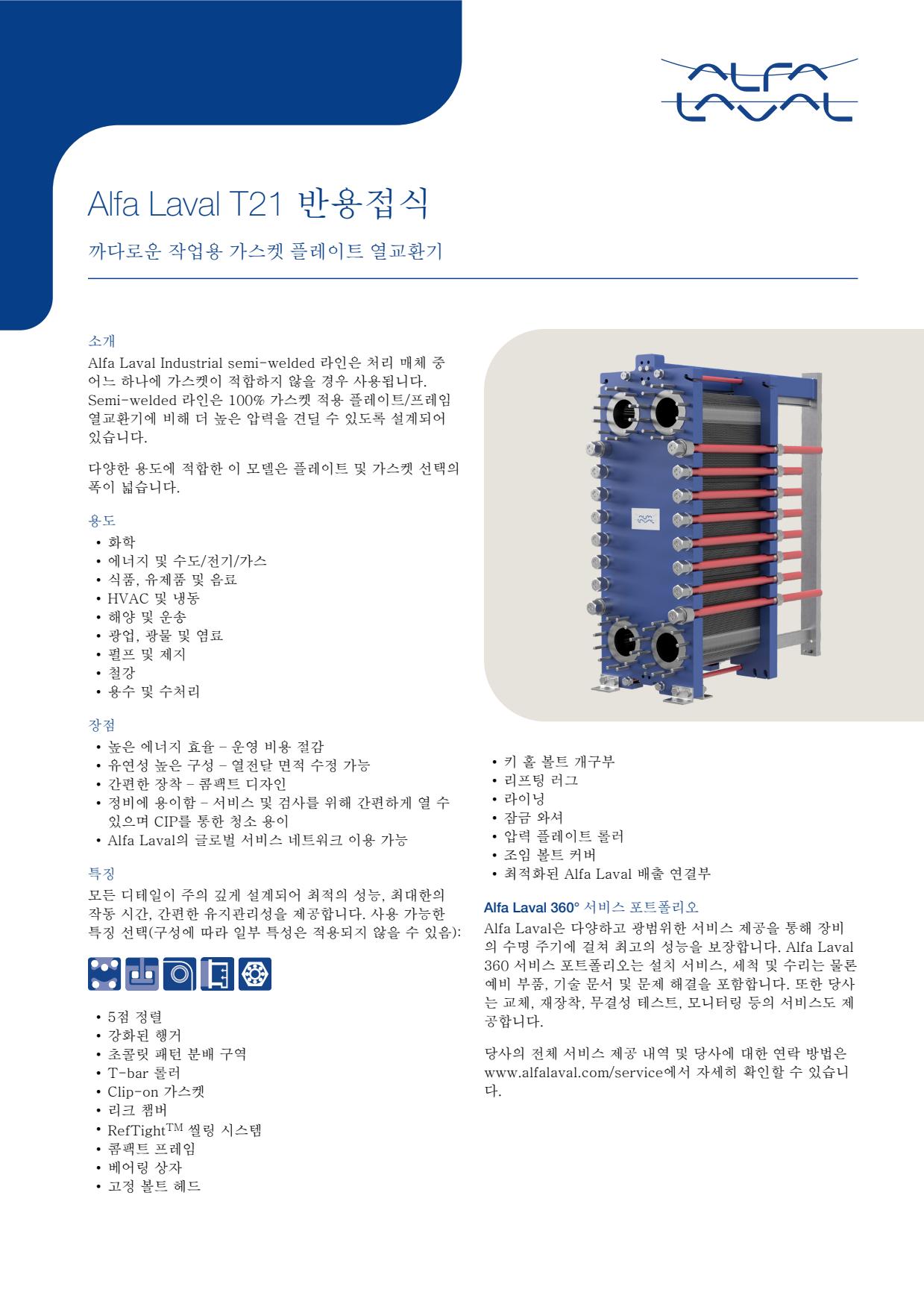
- Plate-channel fouling or scaling caused by contaminated fluid can increase pressure drop and reduce heat-transfer performance
- Aged, damaged or incorrectly seated gaskets can cause external leakage or mixing at the plate edge
- Corrosion, erosion or cracking of a plate can cause internal cross-contamination indicated by unexpected fluid quality, tank level or pressure changes
- Incorrect plate sequence or uneven tightening after maintenance can cause leakage, poor flow distribution or reduced thermal performance
- Blocked strainers or restricted upstream piping can reduce flow and produce abnormal inlet-to-outlet temperatures
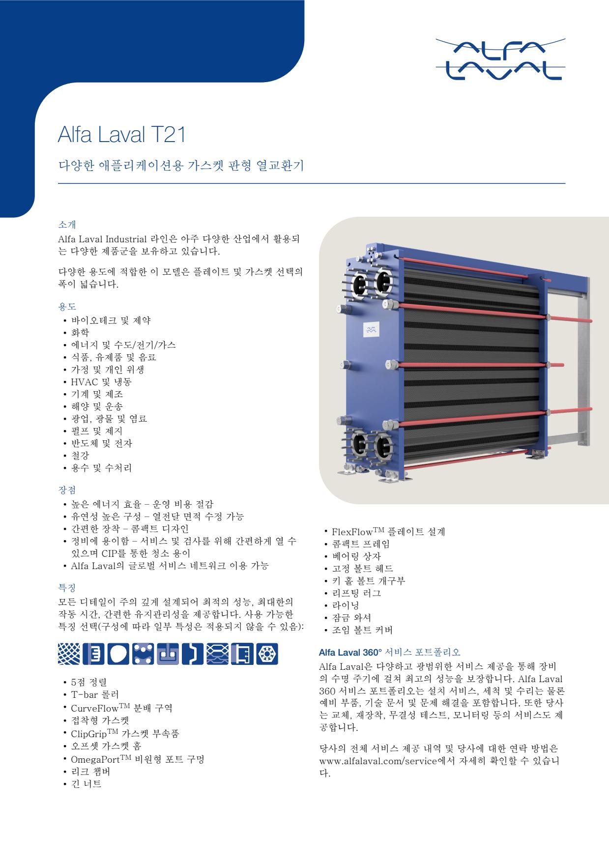
- Plate-channel fouling or scaling caused by contaminated fluid can increase pressure drop and reduce heat-transfer performance
- Aged, damaged or incorrectly seated gaskets can cause external leakage or mixing at the plate edge
- Corrosion, erosion or cracking of a plate can cause internal cross-contamination indicated by unexpected fluid quality, tank level or pressure changes
- Incorrect plate sequence or uneven tightening after maintenance can cause leakage, poor flow distribution or reduced thermal performance
- Blocked strainers or restricted upstream piping can reduce flow and produce abnormal inlet-to-outlet temperatures
- Plate-channel fouling or scaling caused by contaminated fluid can increase pressure drop and reduce heat-transfer performance
- Aged, damaged or incorrectly seated gaskets can cause external leakage or mixing at the plate edge
- Corrosion, erosion or cracking of a plate can cause internal cross-contamination indicated by unexpected fluid quality, tank level or pressure changes
- Incorrect plate sequence or uneven tightening after maintenance can cause leakage, poor flow distribution or reduced thermal performance
- Blocked strainers or restricted upstream piping can reduce flow and produce abnormal inlet-to-outlet temperatures
- Plate-channel fouling or scaling caused by contaminated fluid can increase pressure drop and reduce heat-transfer performance
- Aged, damaged or incorrectly seated gaskets can cause external leakage or mixing at the plate edge
- Corrosion, erosion or cracking of a plate can cause internal cross-contamination indicated by unexpected fluid quality, tank level or pressure changes
- Incorrect plate sequence or uneven tightening after maintenance can cause leakage, poor flow distribution or reduced thermal performance
- Blocked strainers or restricted upstream piping can reduce flow and produce abnormal inlet-to-outlet temperatures
- Plate-channel fouling or scaling caused by contaminated fluid can increase pressure drop and reduce heat-transfer performance
- Aged, damaged or incorrectly seated gaskets can cause external leakage or mixing at the plate edge
- Corrosion, erosion or cracking of a plate can cause internal cross-contamination indicated by unexpected fluid quality, tank level or pressure changes
- Incorrect plate sequence or uneven tightening after maintenance can cause leakage, poor flow distribution or reduced thermal performance
- Blocked strainers or restricted upstream piping can reduce flow and produce abnormal inlet-to-outlet temperatures
- Plate-channel fouling or scaling caused by contaminated fluid can increase pressure drop and reduce heat-transfer performance
- Aged, damaged or incorrectly seated gaskets can cause external leakage or mixing at the plate edge
- Corrosion, erosion or cracking of a plate can cause internal cross-contamination indicated by unexpected fluid quality, tank level or pressure changes
- Incorrect plate sequence or uneven tightening after maintenance can cause leakage, poor flow distribution or reduced thermal performance
- Blocked strainers or restricted upstream piping can reduce flow and produce abnormal inlet-to-outlet temperatures
- Plate-channel fouling or scaling caused by contaminated fluid can increase pressure drop and reduce heat-transfer performance
- Aged, damaged or incorrectly seated gaskets can cause external leakage or mixing at the plate edge
- Corrosion, erosion or cracking of a plate can cause internal cross-contamination indicated by unexpected fluid quality, tank level or pressure changes
- Incorrect plate sequence or uneven tightening after maintenance can cause leakage, poor flow distribution or reduced thermal performance
- Blocked strainers or restricted upstream piping can reduce flow and produce abnormal inlet-to-outlet temperatures
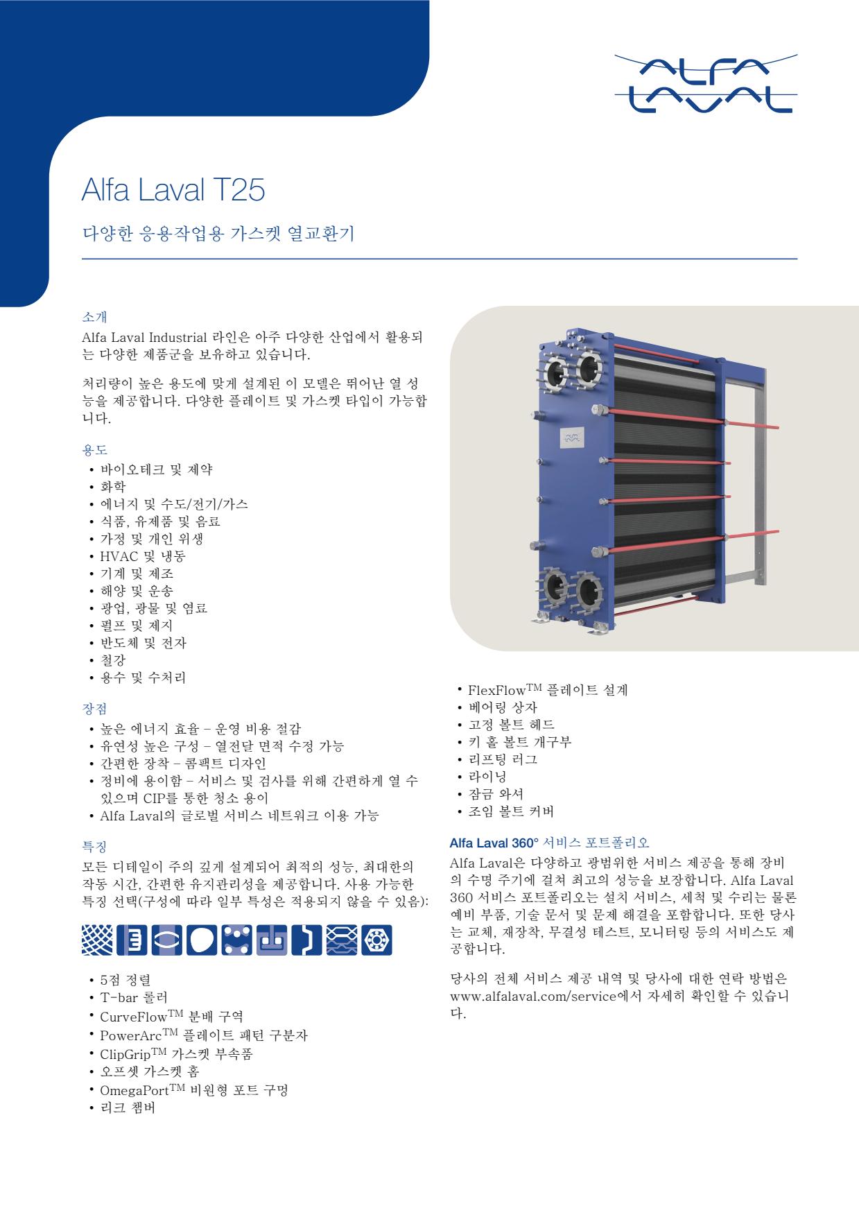
- Plate-channel fouling or scaling caused by contaminated fluid can increase pressure drop and reduce heat-transfer performance
- Aged, damaged or incorrectly seated gaskets can cause external leakage or mixing at the plate edge
- Corrosion, erosion or cracking of a plate can cause internal cross-contamination indicated by unexpected fluid quality, tank level or pressure changes
- Incorrect plate sequence or uneven tightening after maintenance can cause leakage, poor flow distribution or reduced thermal performance
- Blocked strainers or restricted upstream piping can reduce flow and produce abnormal inlet-to-outlet temperatures
- Plate-channel fouling or scaling caused by contaminated fluid can increase pressure drop and reduce heat-transfer performance
- Aged, damaged or incorrectly seated gaskets can cause external leakage or mixing at the plate edge
- Corrosion, erosion or cracking of a plate can cause internal cross-contamination indicated by unexpected fluid quality, tank level or pressure changes
- Incorrect plate sequence or uneven tightening after maintenance can cause leakage, poor flow distribution or reduced thermal performance
- Blocked strainers or restricted upstream piping can reduce flow and produce abnormal inlet-to-outlet temperatures
- Plate-channel fouling or scaling caused by contaminated fluid can increase pressure drop and reduce heat-transfer performance
- Aged, damaged or incorrectly seated gaskets can cause external leakage or mixing at the plate edge
- Corrosion, erosion or cracking of a plate can cause internal cross-contamination indicated by unexpected fluid quality, tank level or pressure changes
- Incorrect plate sequence or uneven tightening after maintenance can cause leakage, poor flow distribution or reduced thermal performance
- Blocked strainers or restricted upstream piping can reduce flow and produce abnormal inlet-to-outlet temperatures
- Plate-channel fouling or scaling caused by contaminated fluid can increase pressure drop and reduce heat-transfer performance
- Aged, damaged or incorrectly seated gaskets can cause external leakage or mixing at the plate edge
- Corrosion, erosion or cracking of a plate can cause internal cross-contamination indicated by unexpected fluid quality, tank level or pressure changes
- Incorrect plate sequence or uneven tightening after maintenance can cause leakage, poor flow distribution or reduced thermal performance
- Blocked strainers or restricted upstream piping can reduce flow and produce abnormal inlet-to-outlet temperatures
- Plate-channel fouling or scaling caused by contaminated fluid can increase pressure drop and reduce heat-transfer performance
- Aged, damaged or incorrectly seated gaskets can cause external leakage or mixing at the plate edge
- Corrosion, erosion or cracking of a plate can cause internal cross-contamination indicated by unexpected fluid quality, tank level or pressure changes
- Incorrect plate sequence or uneven tightening after maintenance can cause leakage, poor flow distribution or reduced thermal performance
- Blocked strainers or restricted upstream piping can reduce flow and produce abnormal inlet-to-outlet temperatures
- Plate-channel fouling or scaling caused by contaminated fluid can increase pressure drop and reduce heat-transfer performance
- Aged, damaged or incorrectly seated gaskets can cause external leakage or mixing at the plate edge
- Corrosion, erosion or cracking of a plate can cause internal cross-contamination indicated by unexpected fluid quality, tank level or pressure changes
- Incorrect plate sequence or uneven tightening after maintenance can cause leakage, poor flow distribution or reduced thermal performance
- Blocked strainers or restricted upstream piping can reduce flow and produce abnormal inlet-to-outlet temperatures
- Plate-channel fouling or scaling caused by contaminated fluid can increase pressure drop and reduce heat-transfer performance
- Aged, damaged or incorrectly seated gaskets can cause external leakage or mixing at the plate edge
- Corrosion, erosion or cracking of a plate can cause internal cross-contamination indicated by unexpected fluid quality, tank level or pressure changes
- Incorrect plate sequence or uneven tightening after maintenance can cause leakage, poor flow distribution or reduced thermal performance
- Blocked strainers or restricted upstream piping can reduce flow and produce abnormal inlet-to-outlet temperatures
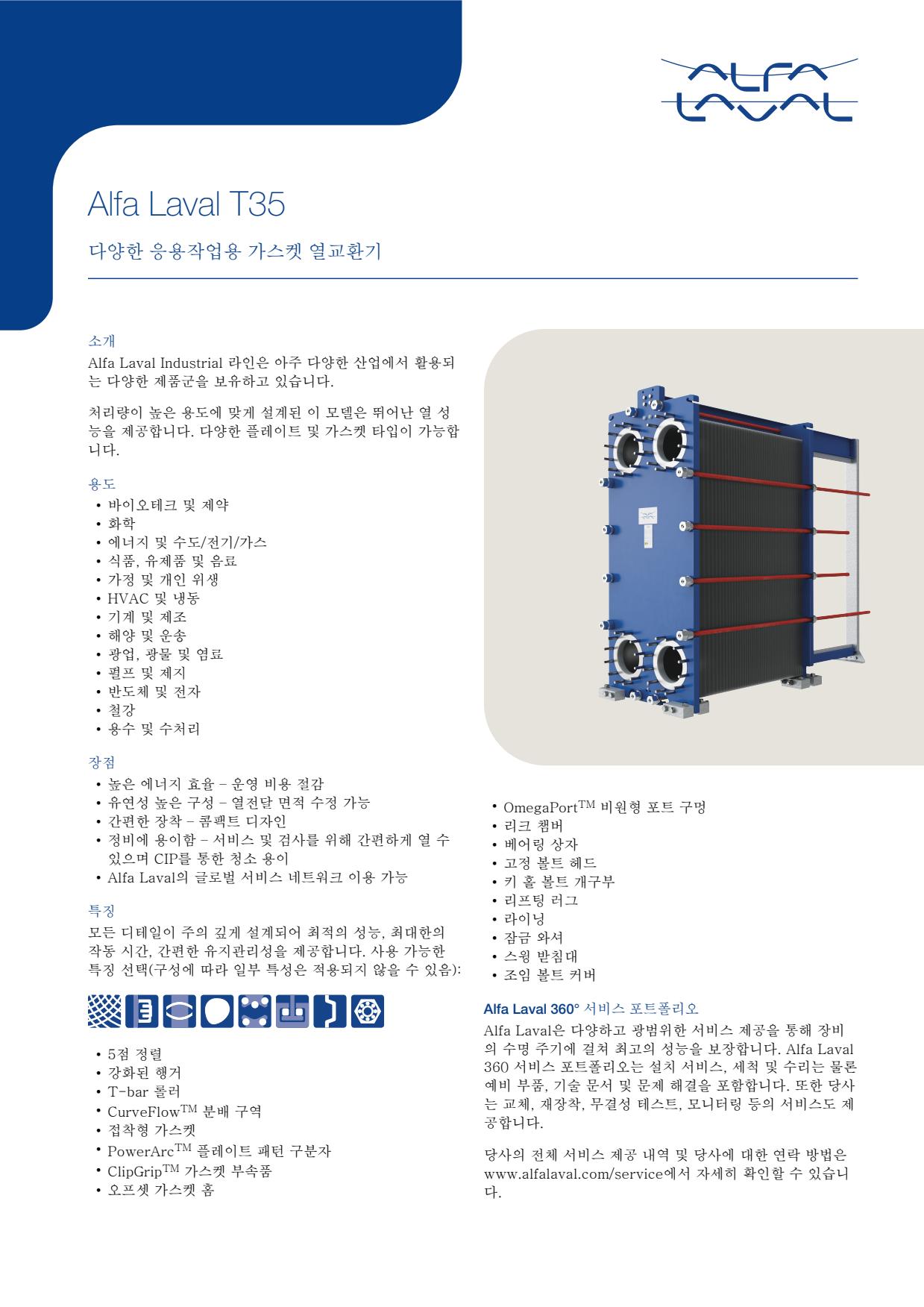
- Plate-channel fouling or scaling caused by contaminated fluid can increase pressure drop and reduce heat-transfer performance
- Aged, damaged or incorrectly seated gaskets can cause external leakage or mixing at the plate edge
- Corrosion, erosion or cracking of a plate can cause internal cross-contamination indicated by unexpected fluid quality, tank level or pressure changes
- Incorrect plate sequence or uneven tightening after maintenance can cause leakage, poor flow distribution or reduced thermal performance
- Blocked strainers or restricted upstream piping can reduce flow and produce abnormal inlet-to-outlet temperatures
- Plate-channel fouling or scaling caused by contaminated fluid can increase pressure drop and reduce heat-transfer performance
- Aged, damaged or incorrectly seated gaskets can cause external leakage or mixing at the plate edge
- Corrosion, erosion or cracking of a plate can cause internal cross-contamination indicated by unexpected fluid quality, tank level or pressure changes
- Incorrect plate sequence or uneven tightening after maintenance can cause leakage, poor flow distribution or reduced thermal performance
- Blocked strainers or restricted upstream piping can reduce flow and produce abnormal inlet-to-outlet temperatures
- Plate-channel fouling or scaling caused by contaminated fluid can increase pressure drop and reduce heat-transfer performance
- Aged, damaged or incorrectly seated gaskets can cause external leakage or mixing at the plate edge
- Corrosion, erosion or cracking of a plate can cause internal cross-contamination indicated by unexpected fluid quality, tank level or pressure changes
- Incorrect plate sequence or uneven tightening after maintenance can cause leakage, poor flow distribution or reduced thermal performance
- Blocked strainers or restricted upstream piping can reduce flow and produce abnormal inlet-to-outlet temperatures
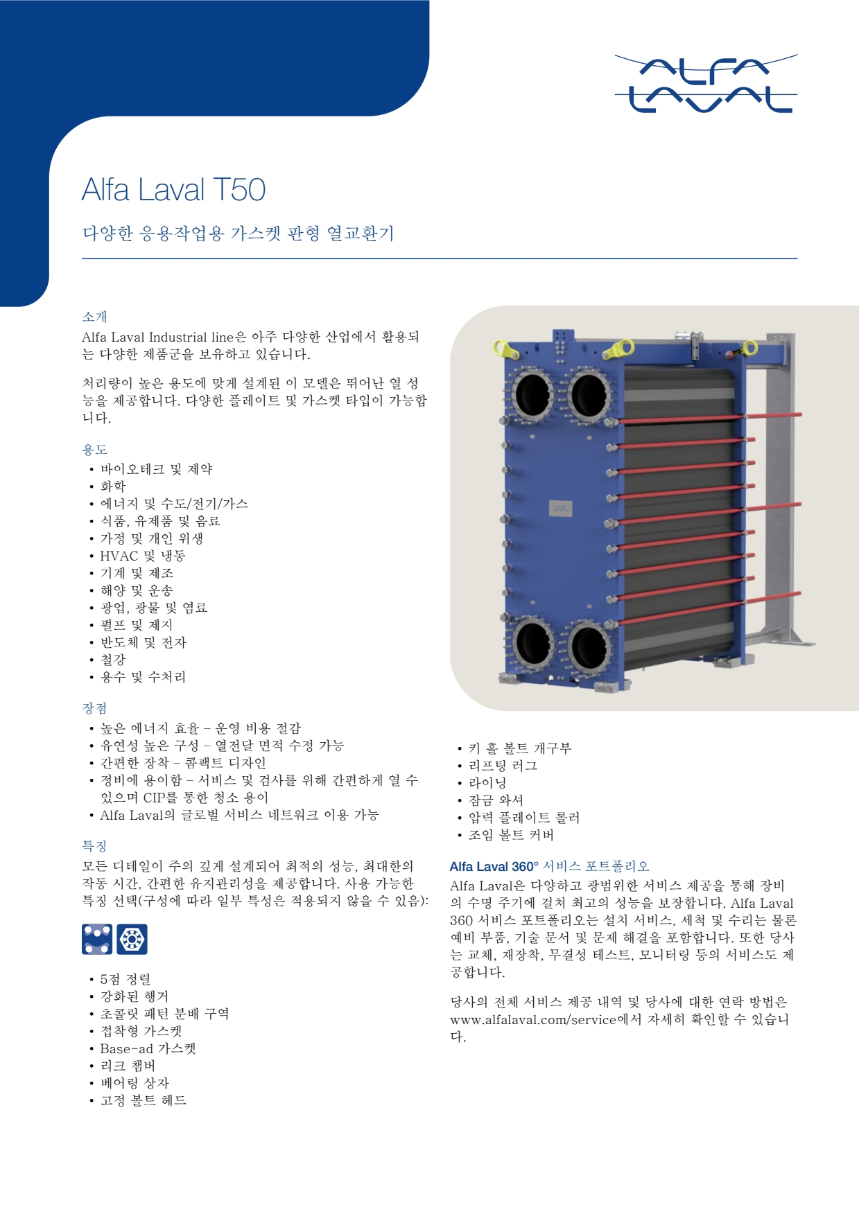
- Plate-channel fouling or scaling caused by contaminated fluid can increase pressure drop and reduce heat-transfer performance
- Aged, damaged or incorrectly seated gaskets can cause external leakage or mixing at the plate edge
- Corrosion, erosion or cracking of a plate can cause internal cross-contamination indicated by unexpected fluid quality, tank level or pressure changes
- Incorrect plate sequence or uneven tightening after maintenance can cause leakage, poor flow distribution or reduced thermal performance
- Blocked strainers or restricted upstream piping can reduce flow and produce abnormal inlet-to-outlet temperatures
- Plate-channel fouling or scaling caused by contaminated fluid can increase pressure drop and reduce heat-transfer performance
- Aged, damaged or incorrectly seated gaskets can cause external leakage or mixing at the plate edge
- Corrosion, erosion or cracking of a plate can cause internal cross-contamination indicated by unexpected fluid quality, tank level or pressure changes
- Incorrect plate sequence or uneven tightening after maintenance can cause leakage, poor flow distribution or reduced thermal performance
- Blocked strainers or restricted upstream piping can reduce flow and produce abnormal inlet-to-outlet temperatures
- Plate-channel fouling or scaling caused by contaminated fluid can increase pressure drop and reduce heat-transfer performance
- Aged, damaged or incorrectly seated gaskets can cause external leakage or mixing at the plate edge
- Corrosion, erosion or cracking of a plate can cause internal cross-contamination indicated by unexpected fluid quality, tank level or pressure changes
- Incorrect plate sequence or uneven tightening after maintenance can cause leakage, poor flow distribution or reduced thermal performance
- Blocked strainers or restricted upstream piping can reduce flow and produce abnormal inlet-to-outlet temperatures
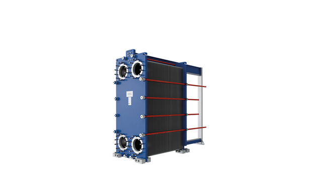
- Plate-channel fouling or scaling caused by contaminated fluid can increase pressure drop and reduce heat-transfer performance
- Aged, damaged or incorrectly seated gaskets can cause external leakage or mixing at the plate edge
- Corrosion, erosion or cracking of a plate can cause internal cross-contamination indicated by unexpected fluid quality, tank level or pressure changes
- Incorrect plate sequence or uneven tightening after maintenance can cause leakage, poor flow distribution or reduced thermal performance
- Blocked strainers or restricted upstream piping can reduce flow and produce abnormal inlet-to-outlet temperatures
- Plate-channel fouling or scaling caused by contaminated fluid can increase pressure drop and reduce heat-transfer performance
- Aged, damaged or incorrectly seated gaskets can cause external leakage or mixing at the plate edge
- Corrosion, erosion or cracking of a plate can cause internal cross-contamination indicated by unexpected fluid quality, tank level or pressure changes
- Incorrect plate sequence or uneven tightening after maintenance can cause leakage, poor flow distribution or reduced thermal performance
- Blocked strainers or restricted upstream piping can reduce flow and produce abnormal inlet-to-outlet temperatures
- Plate-channel fouling or scaling caused by contaminated fluid can increase pressure drop and reduce heat-transfer performance
- Aged, damaged or incorrectly seated gaskets can cause external leakage or mixing at the plate edge
- Corrosion, erosion or cracking of a plate can cause internal cross-contamination indicated by unexpected fluid quality, tank level or pressure changes
- Incorrect plate sequence or uneven tightening after maintenance can cause leakage, poor flow distribution or reduced thermal performance
- Blocked strainers or restricted upstream piping can reduce flow and produce abnormal inlet-to-outlet temperatures
- Plate-channel fouling or scaling caused by contaminated fluid can increase pressure drop and reduce heat-transfer performance
- Aged, damaged or incorrectly seated gaskets can cause external leakage or mixing at the plate edge
- Corrosion, erosion or cracking of a plate can cause internal cross-contamination indicated by unexpected fluid quality, tank level or pressure changes
- Incorrect plate sequence or uneven tightening after maintenance can cause leakage, poor flow distribution or reduced thermal performance
- Blocked strainers or restricted upstream piping can reduce flow and produce abnormal inlet-to-outlet temperatures
- Plate-channel fouling or scaling caused by contaminated fluid can increase pressure drop and reduce heat-transfer performance
- Aged, damaged or incorrectly seated gaskets can cause external leakage or mixing at the plate edge
- Corrosion, erosion or cracking of a plate can cause internal cross-contamination indicated by unexpected fluid quality, tank level or pressure changes
- Incorrect plate sequence or uneven tightening after maintenance can cause leakage, poor flow distribution or reduced thermal performance
- Blocked strainers or restricted upstream piping can reduce flow and produce abnormal inlet-to-outlet temperatures
- Plate-channel fouling or scaling caused by contaminated fluid can increase pressure drop and reduce heat-transfer performance
- Aged, damaged or incorrectly seated gaskets can cause external leakage or mixing at the plate edge
- Corrosion, erosion or cracking of a plate can cause internal cross-contamination indicated by unexpected fluid quality, tank level or pressure changes
- Incorrect plate sequence or uneven tightening after maintenance can cause leakage, poor flow distribution or reduced thermal performance
- Blocked strainers or restricted upstream piping can reduce flow and produce abnormal inlet-to-outlet temperatures
- Plate-channel fouling or scaling caused by contaminated fluid can increase pressure drop and reduce heat-transfer performance
- Aged, damaged or incorrectly seated gaskets can cause external leakage or mixing at the plate edge
- Corrosion, erosion or cracking of a plate can cause internal cross-contamination indicated by unexpected fluid quality, tank level or pressure changes
- Incorrect plate sequence or uneven tightening after maintenance can cause leakage, poor flow distribution or reduced thermal performance
- Blocked strainers or restricted upstream piping can reduce flow and produce abnormal inlet-to-outlet temperatures
- Plate-channel fouling or scaling caused by contaminated fluid can increase pressure drop and reduce heat-transfer performance
- Aged, damaged or incorrectly seated gaskets can cause external leakage or mixing at the plate edge
- Corrosion, erosion or cracking of a plate can cause internal cross-contamination indicated by unexpected fluid quality, tank level or pressure changes
- Incorrect plate sequence or uneven tightening after maintenance can cause leakage, poor flow distribution or reduced thermal performance
- Blocked strainers or restricted upstream piping can reduce flow and produce abnormal inlet-to-outlet temperatures
- Plate-channel fouling or scaling caused by contaminated fluid can increase pressure drop and reduce heat-transfer performance
- Aged, damaged or incorrectly seated gaskets can cause external leakage or mixing at the plate edge
- Corrosion, erosion or cracking of a plate can cause internal cross-contamination indicated by unexpected fluid quality, tank level or pressure changes
- Incorrect plate sequence or uneven tightening after maintenance can cause leakage, poor flow distribution or reduced thermal performance
- Blocked strainers or restricted upstream piping can reduce flow and produce abnormal inlet-to-outlet temperatures
- Plate-channel fouling or scaling caused by contaminated fluid can increase pressure drop and reduce heat-transfer performance
- Aged, damaged or incorrectly seated gaskets can cause external leakage or mixing at the plate edge
- Corrosion, erosion or cracking of a plate can cause internal cross-contamination indicated by unexpected fluid quality, tank level or pressure changes
- Incorrect plate sequence or uneven tightening after maintenance can cause leakage, poor flow distribution or reduced thermal performance
- Blocked strainers or restricted upstream piping can reduce flow and produce abnormal inlet-to-outlet temperatures
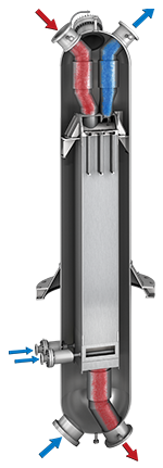
- Fouling or scaling inside narrow plate channels can increase pressure drop and reduce heat transfer
- Corrosion, erosion or fatigue damage can create internal leakage between circuits, indicated by cross-contamination or unexplained changes in fluid condition
- External connection leakage caused by damaged joints or piping loads can produce visible fluid loss
- Freezing, thermal shock or operation outside the approved envelope can damage the plate pack and cause leakage
- Blocked strainers or inadequate circulation can reduce flow and produce abnormal outlet temperatures
- Plate-channel fouling or scaling caused by contaminated fluid can increase pressure drop and reduce heat-transfer performance
- Aged, damaged or incorrectly seated gaskets can cause external leakage or mixing at the plate edge
- Corrosion, erosion or cracking of a plate can cause internal cross-contamination indicated by unexpected fluid quality, tank level or pressure changes
- Incorrect plate sequence or uneven tightening after maintenance can cause leakage, poor flow distribution or reduced thermal performance
- Blocked strainers or restricted upstream piping can reduce flow and produce abnormal inlet-to-outlet temperatures
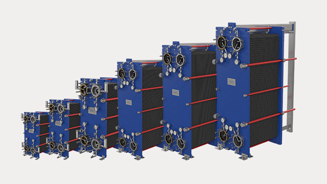
- Plate-channel fouling or scaling caused by contaminated fluid can increase pressure drop and reduce heat-transfer performance
- Aged, damaged or incorrectly seated gaskets can cause external leakage or mixing at the plate edge
- Corrosion, erosion or cracking of a plate can cause internal cross-contamination indicated by unexpected fluid quality, tank level or pressure changes
- Incorrect plate sequence or uneven tightening after maintenance can cause leakage, poor flow distribution or reduced thermal performance
- Blocked strainers or restricted upstream piping can reduce flow and produce abnormal inlet-to-outlet temperatures
- Plate-channel fouling or scaling caused by contaminated fluid can increase pressure drop and reduce heat-transfer performance
- Aged, damaged or incorrectly seated gaskets can cause external leakage or mixing at the plate edge
- Corrosion, erosion or cracking of a plate can cause internal cross-contamination indicated by unexpected fluid quality, tank level or pressure changes
- Incorrect plate sequence or uneven tightening after maintenance can cause leakage, poor flow distribution or reduced thermal performance
- Blocked strainers or restricted upstream piping can reduce flow and produce abnormal inlet-to-outlet temperatures
- Plate-channel fouling or scaling caused by contaminated fluid can increase pressure drop and reduce heat-transfer performance
- Aged, damaged or incorrectly seated gaskets can cause external leakage or mixing at the plate edge
- Corrosion, erosion or cracking of a plate can cause internal cross-contamination indicated by unexpected fluid quality, tank level or pressure changes
- Incorrect plate sequence or uneven tightening after maintenance can cause leakage, poor flow distribution or reduced thermal performance
- Blocked strainers or restricted upstream piping can reduce flow and produce abnormal inlet-to-outlet temperatures
- Plate-channel fouling or scaling caused by contaminated fluid can increase pressure drop and reduce heat-transfer performance
- Aged, damaged or incorrectly seated gaskets can cause external leakage or mixing at the plate edge
- Corrosion, erosion or cracking of a plate can cause internal cross-contamination indicated by unexpected fluid quality, tank level or pressure changes
- Incorrect plate sequence or uneven tightening after maintenance can cause leakage, poor flow distribution or reduced thermal performance
- Blocked strainers or restricted upstream piping can reduce flow and produce abnormal inlet-to-outlet temperatures
- Plate-channel fouling or scaling caused by contaminated fluid can increase pressure drop and reduce heat-transfer performance
- Aged, damaged or incorrectly seated gaskets can cause external leakage or mixing at the plate edge
- Corrosion, erosion or cracking of a plate can cause internal cross-contamination indicated by unexpected fluid quality, tank level or pressure changes
- Incorrect plate sequence or uneven tightening after maintenance can cause leakage, poor flow distribution or reduced thermal performance
- Blocked strainers or restricted upstream piping can reduce flow and produce abnormal inlet-to-outlet temperatures
- Plate-channel fouling or scaling caused by contaminated fluid can increase pressure drop and reduce heat-transfer performance
- Aged, damaged or incorrectly seated gaskets can cause external leakage or mixing at the plate edge
- Corrosion, erosion or cracking of a plate can cause internal cross-contamination indicated by unexpected fluid quality, tank level or pressure changes
- Incorrect plate sequence or uneven tightening after maintenance can cause leakage, poor flow distribution or reduced thermal performance
- Blocked strainers or restricted upstream piping can reduce flow and produce abnormal inlet-to-outlet temperatures
- Plate-channel fouling or scaling caused by contaminated fluid can increase pressure drop and reduce heat-transfer performance
- Aged, damaged or incorrectly seated gaskets can cause external leakage or mixing at the plate edge
- Corrosion, erosion or cracking of a plate can cause internal cross-contamination indicated by unexpected fluid quality, tank level or pressure changes
- Incorrect plate sequence or uneven tightening after maintenance can cause leakage, poor flow distribution or reduced thermal performance
- Blocked strainers or restricted upstream piping can reduce flow and produce abnormal inlet-to-outlet temperatures
- Plate-channel fouling or scaling caused by contaminated fluid can increase pressure drop and reduce heat-transfer performance
- Aged, damaged or incorrectly seated gaskets can cause external leakage or mixing at the plate edge
- Corrosion, erosion or cracking of a plate can cause internal cross-contamination indicated by unexpected fluid quality, tank level or pressure changes
- Incorrect plate sequence or uneven tightening after maintenance can cause leakage, poor flow distribution or reduced thermal performance
- Blocked strainers or restricted upstream piping can reduce flow and produce abnormal inlet-to-outlet temperatures
- Plate-channel fouling or scaling caused by contaminated fluid can increase pressure drop and reduce heat-transfer performance
- Aged, damaged or incorrectly seated gaskets can cause external leakage or mixing at the plate edge
- Corrosion, erosion or cracking of a plate can cause internal cross-contamination indicated by unexpected fluid quality, tank level or pressure changes
- Incorrect plate sequence or uneven tightening after maintenance can cause leakage, poor flow distribution or reduced thermal performance
- Blocked strainers or restricted upstream piping can reduce flow and produce abnormal inlet-to-outlet temperatures
- Plate-channel fouling or scaling caused by contaminated fluid can increase pressure drop and reduce heat-transfer performance
- Aged, damaged or incorrectly seated gaskets can cause external leakage or mixing at the plate edge
- Corrosion, erosion or cracking of a plate can cause internal cross-contamination indicated by unexpected fluid quality, tank level or pressure changes
- Incorrect plate sequence or uneven tightening after maintenance can cause leakage, poor flow distribution or reduced thermal performance
- Blocked strainers or restricted upstream piping can reduce flow and produce abnormal inlet-to-outlet temperatures
- Plate-channel fouling or scaling caused by contaminated fluid can increase pressure drop and reduce heat-transfer performance
- Aged, damaged or incorrectly seated gaskets can cause external leakage or mixing at the plate edge
- Corrosion, erosion or cracking of a plate can cause internal cross-contamination indicated by unexpected fluid quality, tank level or pressure changes
- Incorrect plate sequence or uneven tightening after maintenance can cause leakage, poor flow distribution or reduced thermal performance
- Blocked strainers or restricted upstream piping can reduce flow and produce abnormal inlet-to-outlet temperatures
- Plate-channel fouling or scaling caused by contaminated fluid can increase pressure drop and reduce heat-transfer performance
- Aged, damaged or incorrectly seated gaskets can cause external leakage or mixing at the plate edge
- Corrosion, erosion or cracking of a plate can cause internal cross-contamination indicated by unexpected fluid quality, tank level or pressure changes
- Incorrect plate sequence or uneven tightening after maintenance can cause leakage, poor flow distribution or reduced thermal performance
- Blocked strainers or restricted upstream piping can reduce flow and produce abnormal inlet-to-outlet temperatures
- Plate-channel fouling or scaling caused by contaminated fluid can increase pressure drop and reduce heat-transfer performance
- Aged, damaged or incorrectly seated gaskets can cause external leakage or mixing at the plate edge
- Corrosion, erosion or cracking of a plate can cause internal cross-contamination indicated by unexpected fluid quality, tank level or pressure changes
- Incorrect plate sequence or uneven tightening after maintenance can cause leakage, poor flow distribution or reduced thermal performance
- Blocked strainers or restricted upstream piping can reduce flow and produce abnormal inlet-to-outlet temperatures
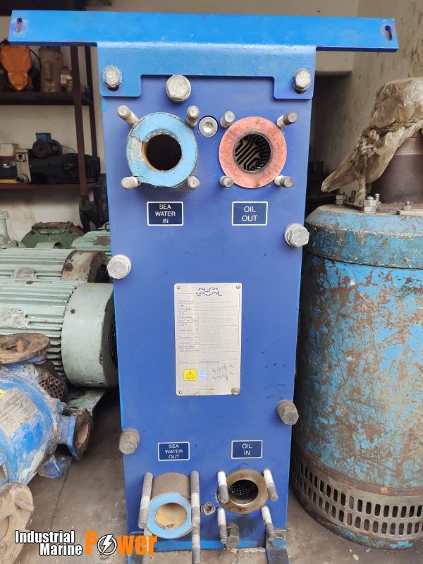
- Plate-channel fouling or scaling caused by contaminated fluid can increase pressure drop and reduce heat-transfer performance
- Aged, damaged or incorrectly seated gaskets can cause external leakage or mixing at the plate edge
- Corrosion, erosion or cracking of a plate can cause internal cross-contamination indicated by unexpected fluid quality, tank level or pressure changes
- Incorrect plate sequence or uneven tightening after maintenance can cause leakage, poor flow distribution or reduced thermal performance
- Blocked strainers or restricted upstream piping can reduce flow and produce abnormal inlet-to-outlet temperatures
- Plate-channel fouling or scaling caused by contaminated fluid can increase pressure drop and reduce heat-transfer performance
- Aged, damaged or incorrectly seated gaskets can cause external leakage or mixing at the plate edge
- Corrosion, erosion or cracking of a plate can cause internal cross-contamination indicated by unexpected fluid quality, tank level or pressure changes
- Incorrect plate sequence or uneven tightening after maintenance can cause leakage, poor flow distribution or reduced thermal performance
- Blocked strainers or restricted upstream piping can reduce flow and produce abnormal inlet-to-outlet temperatures

- Plate-channel fouling or scaling caused by contaminated fluid can increase pressure drop and reduce heat-transfer performance
- Aged, damaged or incorrectly seated gaskets can cause external leakage or mixing at the plate edge
- Corrosion, erosion or cracking of a plate can cause internal cross-contamination indicated by unexpected fluid quality, tank level or pressure changes
- Incorrect plate sequence or uneven tightening after maintenance can cause leakage, poor flow distribution or reduced thermal performance
- Blocked strainers or restricted upstream piping can reduce flow and produce abnormal inlet-to-outlet temperatures
- Plate-channel fouling or scaling caused by contaminated fluid can increase pressure drop and reduce heat-transfer performance
- Aged, damaged or incorrectly seated gaskets can cause external leakage or mixing at the plate edge
- Corrosion, erosion or cracking of a plate can cause internal cross-contamination indicated by unexpected fluid quality, tank level or pressure changes
- Incorrect plate sequence or uneven tightening after maintenance can cause leakage, poor flow distribution or reduced thermal performance
- Blocked strainers or restricted upstream piping can reduce flow and produce abnormal inlet-to-outlet temperatures
- Plate-channel fouling or scaling caused by contaminated fluid can increase pressure drop and reduce heat-transfer performance
- Aged, damaged or incorrectly seated gaskets can cause external leakage or mixing at the plate edge
- Corrosion, erosion or cracking of a plate can cause internal cross-contamination indicated by unexpected fluid quality, tank level or pressure changes
- Incorrect plate sequence or uneven tightening after maintenance can cause leakage, poor flow distribution or reduced thermal performance
- Blocked strainers or restricted upstream piping can reduce flow and produce abnormal inlet-to-outlet temperatures
-facing-left.png)

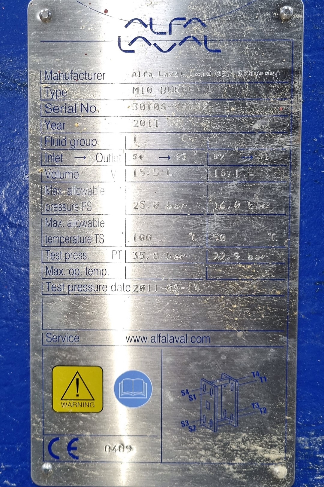


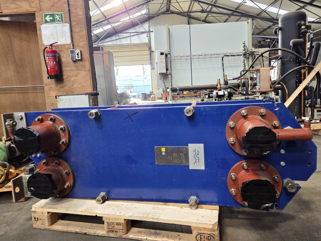
- Fouling on the heat-transfer surfaces from scale, sludge, biological growth, or oil contamination reduces thermal performance and appears as rising outlet temperature or reduced temperature approach
- Gasket, seal, tube, or plate leakage caused by ageing, corrosion, or mechanical damage can allow external leakage or cross-contamination between circuits
- Restricted flow from debris or deposits raises differential pressure and can reduce downstream flow
- Corrosion or erosion of wetted surfaces caused by unsuitable water chemistry, velocity, or material attack can produce pinhole leakage and contamination
- Loose covers, plate packs, or connections after maintenance can cause leakage, unstable temperatures, or loss of system pressure
- Fouling on the heat-transfer surfaces from scale, sludge, biological growth, or oil contamination reduces thermal performance and appears as rising outlet temperature or reduced temperature approach
- Gasket, seal, tube, or plate leakage caused by ageing, corrosion, or mechanical damage can allow external leakage or cross-contamination between circuits
- Restricted flow from debris or deposits raises differential pressure and can reduce downstream flow
- Corrosion or erosion of wetted surfaces caused by unsuitable water chemistry, velocity, or material attack can produce pinhole leakage and contamination
- Loose covers, plate packs, or connections after maintenance can cause leakage, unstable temperatures, or loss of system pressure
- Fouling on the heat-transfer surfaces from scale, sludge, biological growth, or oil contamination reduces thermal performance and appears as rising outlet temperature or reduced temperature approach
- Gasket, seal, tube, or plate leakage caused by ageing, corrosion, or mechanical damage can allow external leakage or cross-contamination between circuits
- Restricted flow from debris or deposits raises differential pressure and can reduce downstream flow
- Corrosion or erosion of wetted surfaces caused by unsuitable water chemistry, velocity, or material attack can produce pinhole leakage and contamination
- Loose covers, plate packs, or connections after maintenance can cause leakage, unstable temperatures, or loss of system pressure
- Fouling on the heat-transfer surfaces from scale, sludge, biological growth, or oil contamination reduces thermal performance and appears as rising outlet temperature or reduced temperature approach
- Gasket, seal, tube, or plate leakage caused by ageing, corrosion, or mechanical damage can allow external leakage or cross-contamination between circuits
- Restricted flow from debris or deposits raises differential pressure and can reduce downstream flow
- Corrosion or erosion of wetted surfaces caused by unsuitable water chemistry, velocity, or material attack can produce pinhole leakage and contamination
- Loose covers, plate packs, or connections after maintenance can cause leakage, unstable temperatures, or loss of system pressure
- Fouling on the heat-transfer surfaces from scale, sludge, biological growth, or oil contamination reduces thermal performance and appears as rising outlet temperature or reduced temperature approach
- Gasket, seal, tube, or plate leakage caused by ageing, corrosion, or mechanical damage can allow external leakage or cross-contamination between circuits
- Restricted flow from debris or deposits raises differential pressure and can reduce downstream flow
- Corrosion or erosion of wetted surfaces caused by unsuitable water chemistry, velocity, or material attack can produce pinhole leakage and contamination
- Loose covers, plate packs, or connections after maintenance can cause leakage, unstable temperatures, or loss of system pressure
- Fouling on the heat-transfer surfaces from scale, sludge, biological growth, or oil contamination reduces thermal performance and appears as rising outlet temperature or reduced temperature approach
- Gasket, seal, tube, or plate leakage caused by ageing, corrosion, or mechanical damage can allow external leakage or cross-contamination between circuits
- Restricted flow from debris or deposits raises differential pressure and can reduce downstream flow
- Corrosion or erosion of wetted surfaces caused by unsuitable water chemistry, velocity, or material attack can produce pinhole leakage and contamination
- Loose covers, plate packs, or connections after maintenance can cause leakage, unstable temperatures, or loss of system pressure
- Fouling on the heat-transfer surfaces from scale, sludge, biological growth, or oil contamination reduces thermal performance and appears as rising outlet temperature or reduced temperature approach
- Gasket, seal, tube, or plate leakage caused by ageing, corrosion, or mechanical damage can allow external leakage or cross-contamination between circuits
- Restricted flow from debris or deposits raises differential pressure and can reduce downstream flow
- Corrosion or erosion of wetted surfaces caused by unsuitable water chemistry, velocity, or material attack can produce pinhole leakage and contamination
- Loose covers, plate packs, or connections after maintenance can cause leakage, unstable temperatures, or loss of system pressure
- Fouling on the heat-transfer surfaces from scale, sludge, biological growth, or oil contamination reduces thermal performance and appears as rising outlet temperature or reduced temperature approach
- Gasket, seal, tube, or plate leakage caused by ageing, corrosion, or mechanical damage can allow external leakage or cross-contamination between circuits
- Restricted flow from debris or deposits raises differential pressure and can reduce downstream flow
- Corrosion or erosion of wetted surfaces caused by unsuitable water chemistry, velocity, or material attack can produce pinhole leakage and contamination
- Loose covers, plate packs, or connections after maintenance can cause leakage, unstable temperatures, or loss of system pressure
- Fouling on the heat-transfer surfaces from scale, sludge, biological growth, or oil contamination reduces thermal performance and appears as rising outlet temperature or reduced temperature approach
- Gasket, seal, tube, or plate leakage caused by ageing, corrosion, or mechanical damage can allow external leakage or cross-contamination between circuits
- Restricted flow from debris or deposits raises differential pressure and can reduce downstream flow
- Corrosion or erosion of wetted surfaces caused by unsuitable water chemistry, velocity, or material attack can produce pinhole leakage and contamination
- Loose covers, plate packs, or connections after maintenance can cause leakage, unstable temperatures, or loss of system pressure
- Fouling on the heat-transfer surfaces from scale, sludge, biological growth, or oil contamination reduces thermal performance and appears as rising outlet temperature or reduced temperature approach
- Gasket, seal, tube, or plate leakage caused by ageing, corrosion, or mechanical damage can allow external leakage or cross-contamination between circuits
- Restricted flow from debris or deposits raises differential pressure and can reduce downstream flow
- Corrosion or erosion of wetted surfaces caused by unsuitable water chemistry, velocity, or material attack can produce pinhole leakage and contamination
- Loose covers, plate packs, or connections after maintenance can cause leakage, unstable temperatures, or loss of system pressure
- Fouling on the heat-transfer surfaces from scale, sludge, biological growth, or oil contamination reduces thermal performance and appears as rising outlet temperature or reduced temperature approach
- Gasket, seal, tube, or plate leakage caused by ageing, corrosion, or mechanical damage can allow external leakage or cross-contamination between circuits
- Restricted flow from debris or deposits raises differential pressure and can reduce downstream flow
- Corrosion or erosion of wetted surfaces caused by unsuitable water chemistry, velocity, or material attack can produce pinhole leakage and contamination
- Loose covers, plate packs, or connections after maintenance can cause leakage, unstable temperatures, or loss of system pressure
- Fouling on the heat-transfer surfaces from scale, sludge, biological growth, or oil contamination reduces thermal performance and appears as rising outlet temperature or reduced temperature approach
- Gasket, seal, tube, or plate leakage caused by ageing, corrosion, or mechanical damage can allow external leakage or cross-contamination between circuits
- Restricted flow from debris or deposits raises differential pressure and can reduce downstream flow
- Corrosion or erosion of wetted surfaces caused by unsuitable water chemistry, velocity, or material attack can produce pinhole leakage and contamination
- Loose covers, plate packs, or connections after maintenance can cause leakage, unstable temperatures, or loss of system pressure
- Fouling on the heat-transfer surfaces from scale, sludge, biological growth, or oil contamination reduces thermal performance and appears as rising outlet temperature or reduced temperature approach
- Gasket, seal, tube, or plate leakage caused by ageing, corrosion, or mechanical damage can allow external leakage or cross-contamination between circuits
- Restricted flow from debris or deposits raises differential pressure and can reduce downstream flow
- Corrosion or erosion of wetted surfaces caused by unsuitable water chemistry, velocity, or material attack can produce pinhole leakage and contamination
- Loose covers, plate packs, or connections after maintenance can cause leakage, unstable temperatures, or loss of system pressure
- Fouling on the heat-transfer surfaces from scale, sludge, biological growth, or oil contamination reduces thermal performance and appears as rising outlet temperature or reduced temperature approach
- Gasket, seal, tube, or plate leakage caused by ageing, corrosion, or mechanical damage can allow external leakage or cross-contamination between circuits
- Restricted flow from debris or deposits raises differential pressure and can reduce downstream flow
- Corrosion or erosion of wetted surfaces caused by unsuitable water chemistry, velocity, or material attack can produce pinhole leakage and contamination
- Loose covers, plate packs, or connections after maintenance can cause leakage, unstable temperatures, or loss of system pressure
- Fouling on the heat-transfer surfaces from scale, sludge, biological growth, or oil contamination reduces thermal performance and appears as rising outlet temperature or reduced temperature approach
- Gasket, seal, tube, or plate leakage caused by ageing, corrosion, or mechanical damage can allow external leakage or cross-contamination between circuits
- Restricted flow from debris or deposits raises differential pressure and can reduce downstream flow
- Corrosion or erosion of wetted surfaces caused by unsuitable water chemistry, velocity, or material attack can produce pinhole leakage and contamination
- Loose covers, plate packs, or connections after maintenance can cause leakage, unstable temperatures, or loss of system pressure
- Fouling on the heat-transfer surfaces from scale, sludge, biological growth, or oil contamination reduces thermal performance and appears as rising outlet temperature or reduced temperature approach
- Gasket, seal, tube, or plate leakage caused by ageing, corrosion, or mechanical damage can allow external leakage or cross-contamination between circuits
- Restricted flow from debris or deposits raises differential pressure and can reduce downstream flow
- Corrosion or erosion of wetted surfaces caused by unsuitable water chemistry, velocity, or material attack can produce pinhole leakage and contamination
- Loose covers, plate packs, or connections after maintenance can cause leakage, unstable temperatures, or loss of system pressure
- Fouling on the heat-transfer surfaces from scale, sludge, biological growth, or oil contamination reduces thermal performance and appears as rising outlet temperature or reduced temperature approach
- Gasket, seal, tube, or plate leakage caused by ageing, corrosion, or mechanical damage can allow external leakage or cross-contamination between circuits
- Restricted flow from debris or deposits raises differential pressure and can reduce downstream flow
- Corrosion or erosion of wetted surfaces caused by unsuitable water chemistry, velocity, or material attack can produce pinhole leakage and contamination
- Loose covers, plate packs, or connections after maintenance can cause leakage, unstable temperatures, or loss of system pressure
- Fouling on the heat-transfer surfaces from scale, sludge, biological growth, or oil contamination reduces thermal performance and appears as rising outlet temperature or reduced temperature approach
- Gasket, seal, tube, or plate leakage caused by ageing, corrosion, or mechanical damage can allow external leakage or cross-contamination between circuits
- Restricted flow from debris or deposits raises differential pressure and can reduce downstream flow
- Corrosion or erosion of wetted surfaces caused by unsuitable water chemistry, velocity, or material attack can produce pinhole leakage and contamination
- Loose covers, plate packs, or connections after maintenance can cause leakage, unstable temperatures, or loss of system pressure
- Fouling on the heat-transfer surfaces from scale, sludge, biological growth, or oil contamination reduces thermal performance and appears as rising outlet temperature or reduced temperature approach
- Gasket, seal, tube, or plate leakage caused by ageing, corrosion, or mechanical damage can allow external leakage or cross-contamination between circuits
- Restricted flow from debris or deposits raises differential pressure and can reduce downstream flow
- Corrosion or erosion of wetted surfaces caused by unsuitable water chemistry, velocity, or material attack can produce pinhole leakage and contamination
- Loose covers, plate packs, or connections after maintenance can cause leakage, unstable temperatures, or loss of system pressure
- Fouling on the heat-transfer surfaces from scale, sludge, biological growth, or oil contamination reduces thermal performance and appears as rising outlet temperature or reduced temperature approach
- Gasket, seal, tube, or plate leakage caused by ageing, corrosion, or mechanical damage can allow external leakage or cross-contamination between circuits
- Restricted flow from debris or deposits raises differential pressure and can reduce downstream flow
- Corrosion or erosion of wetted surfaces caused by unsuitable water chemistry, velocity, or material attack can produce pinhole leakage and contamination
- Loose covers, plate packs, or connections after maintenance can cause leakage, unstable temperatures, or loss of system pressure
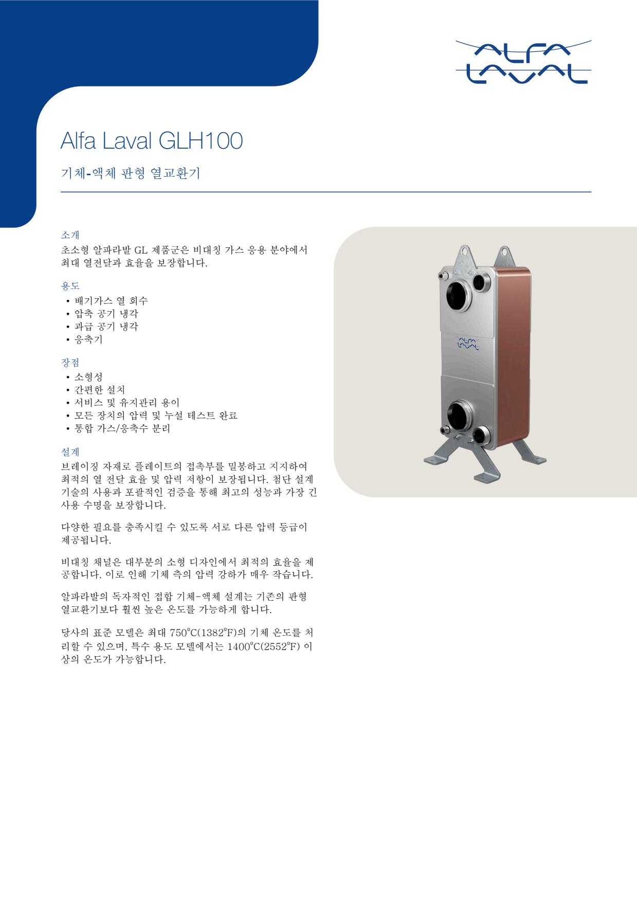
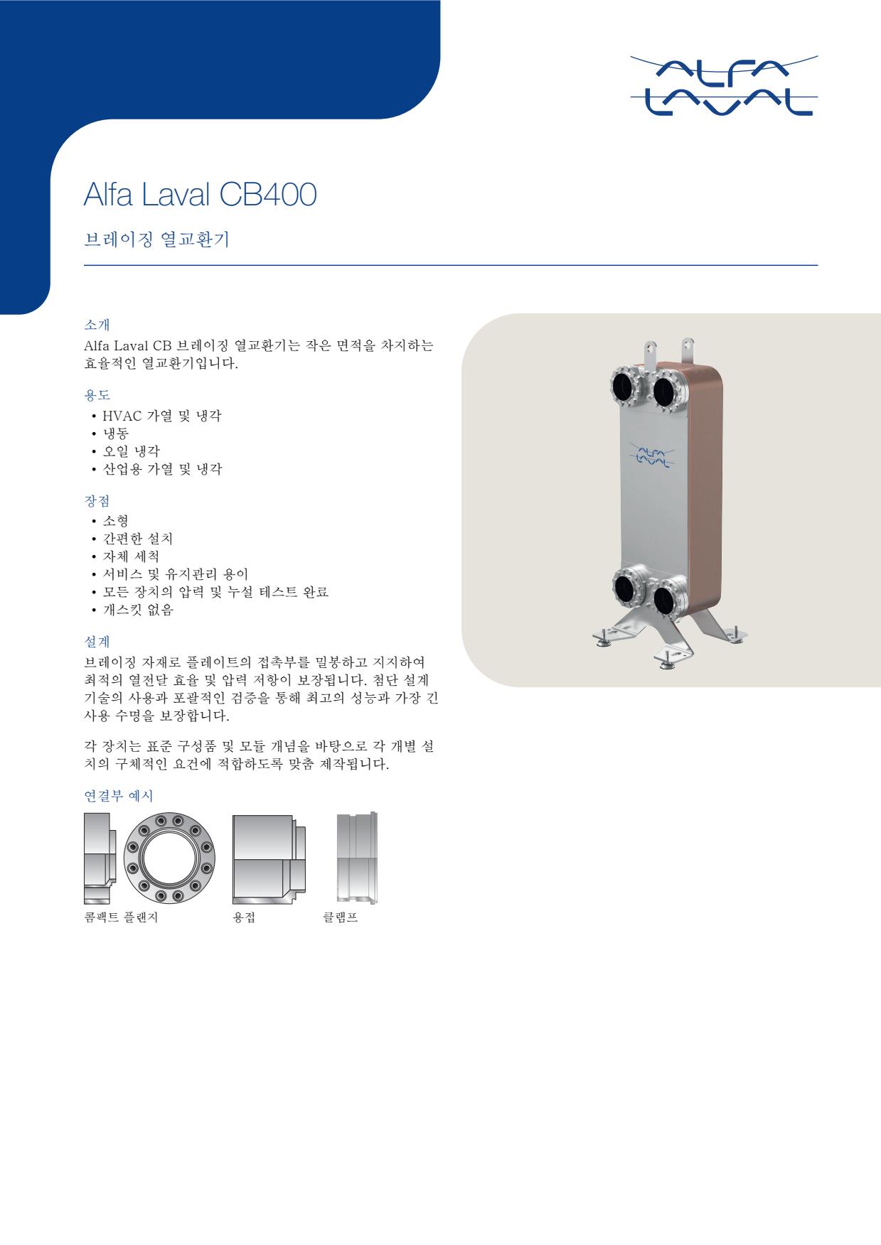
GEA
80- Fouling or scaling increases differential pressure and reduces heat-transfer performance
- Gasket, seal or tube-joint deterioration causes external leakage
- Plate or tube corrosion, erosion or cracking causes internal cross-contamination between fluid circuits
- Blocked strainers or restricted valves reduce flow and produce abnormal inlet-to-outlet temperatures
- Incorrect reassembly, venting or flow distribution after service causes leakage or poor thermal performance
- High heat transfer efficiency in a small footprint
- Glue‑free, clip‑on gasket system enables fast plate removal and inspection
- Stainless‑steel frame provides good corrosion resistance for marine service
- Modular design allows capacity scaling by adding or removing plates
- Suitable for a wide range of media (FW, SW, low‑viscosity oil)
- Gasket material can compress set over time, requiring periodic replacement
- Susceptible to chloride‑induced pitting on plates if water treatment is inadequate
- Limited to moderate pressures/temperatures compared with welded plate exchangers
- Fouling risk in high‑particulate seawater; requires regular cleaning schedule
- Fouling on the heat-transfer surfaces from scale, sludge, biological growth, or oil contamination reduces thermal performance and appears as rising outlet temperature or reduced temperature approach
- Gasket, seal, tube, or plate leakage caused by ageing, corrosion, or mechanical damage can allow external leakage or cross-contamination between circuits
- Restricted flow from debris or deposits raises differential pressure and can reduce downstream flow
- Corrosion or erosion of wetted surfaces caused by unsuitable water chemistry, velocity, or material attack can produce pinhole leakage and contamination
- Loose covers, plate packs, or connections after maintenance can cause leakage, unstable temperatures, or loss of system pressure
- Fouling on the heat-transfer surfaces from scale, sludge, biological growth, or oil contamination reduces thermal performance and appears as rising outlet temperature or reduced temperature approach
- Gasket, seal, tube, or plate leakage caused by ageing, corrosion, or mechanical damage can allow external leakage or cross-contamination between circuits
- Restricted flow from debris or deposits raises differential pressure and can reduce downstream flow
- Corrosion or erosion of wetted surfaces caused by unsuitable water chemistry, velocity, or material attack can produce pinhole leakage and contamination
- Loose covers, plate packs, or connections after maintenance can cause leakage, unstable temperatures, or loss of system pressure
- Fouling on the heat-transfer surfaces from scale, sludge, biological growth, or oil contamination reduces thermal performance and appears as rising outlet temperature or reduced temperature approach
- Gasket, seal, tube, or plate leakage caused by ageing, corrosion, or mechanical damage can allow external leakage or cross-contamination between circuits
- Restricted flow from debris or deposits raises differential pressure and can reduce downstream flow
- Corrosion or erosion of wetted surfaces caused by unsuitable water chemistry, velocity, or material attack can produce pinhole leakage and contamination
- Loose covers, plate packs, or connections after maintenance can cause leakage, unstable temperatures, or loss of system pressure
- Fouling or scaling increases differential pressure and reduces heat-transfer performance
- Gasket, seal or tube-joint deterioration causes external leakage
- Plate or tube corrosion, erosion or cracking causes internal cross-contamination between fluid circuits
- Blocked strainers or restricted valves reduce flow and produce abnormal inlet-to-outlet temperatures
- Incorrect reassembly, venting or flow distribution after service causes leakage or poor thermal performance
- Plate fouling or scale reduces heat transfer, noticed as poor outlet temperatures and increasing temperature approach
- Gasket ageing or incorrect plate compression causes external leakage between plate edges
- Plate perforation can allow cross-contamination, noticed as unexpected level, pressure or fluid-quality changes
- Blocked passages increase pressure drop and reduce circulation through the exchanger
- Corrosion or erosion damages plates and can lead to repeated leakage
- Fouling or scaling increases differential pressure and reduces heat-transfer performance
- Gasket, seal or tube-joint deterioration causes external leakage
- Plate or tube corrosion, erosion or cracking causes internal cross-contamination between fluid circuits
- Blocked strainers or restricted valves reduce flow and produce abnormal inlet-to-outlet temperatures
- Incorrect reassembly, venting or flow distribution after service causes leakage or poor thermal performance
- Fouling or deposit build-up caused by poor combustion, contaminated fluid or exhaust soot can reduce heat transfer or flow and produce higher temperatures or loss of capacity
- Leakage from tubes, gaskets, seals or casing caused by corrosion, thermal cycling or erosion can appear as fluid loss, pressure decay or cross-contamination
- Burner, ignition or fuel-control faults where combustion is used can cause flame failure, unstable firing, smoke or shutdown alarms
- Fan, pump or actuator faults caused by mechanical wear or electrical problems can reduce circulation, airflow or treatment effectiveness
- Sensor, control or safety-interlock faults caused by drift, wiring defects or contamination can trigger nuisance trips or allow unstable operation
- Fouling or deposit build-up caused by poor combustion, contaminated fluid or exhaust soot can reduce heat transfer or flow and produce higher temperatures or loss of capacity
- Leakage from tubes, gaskets, seals or casing caused by corrosion, thermal cycling or erosion can appear as fluid loss, pressure decay or cross-contamination
- Burner, ignition or fuel-control faults where combustion is used can cause flame failure, unstable firing, smoke or shutdown alarms
- Fan, pump or actuator faults caused by mechanical wear or electrical problems can reduce circulation, airflow or treatment effectiveness
- Sensor, control or safety-interlock faults caused by drift, wiring defects or contamination can trigger nuisance trips or allow unstable operation
- Fouling or deposit build-up caused by poor combustion, contaminated fluid or exhaust soot can reduce heat transfer or flow and produce higher temperatures or loss of capacity
- Leakage from tubes, gaskets, seals or casing caused by corrosion, thermal cycling or erosion can appear as fluid loss, pressure decay or cross-contamination
- Burner, ignition or fuel-control faults where combustion is used can cause flame failure, unstable firing, smoke or shutdown alarms
- Fan, pump or actuator faults caused by mechanical wear or electrical problems can reduce circulation, airflow or treatment effectiveness
- Sensor, control or safety-interlock faults caused by drift, wiring defects or contamination can trigger nuisance trips or allow unstable operation
- Fouling on heat-transfer surfaces from scale, sludge, biological growth, or oil contamination reduces thermal performance and appears as rising outlet temperature
- Gasket, seal, tube, or plate leakage from ageing, corrosion, or mechanical damage causes external leakage or cross-contamination
- Restricted flow from debris or deposits raises pressure drop and reduces downstream flow
- Corrosion or erosion of wetted surfaces from unsuitable water chemistry, velocity, or material attack produces pinhole leakage
- Loose covers, plate packs, or connections after maintenance cause leakage, unstable temperatures, or loss of system pressure
- Fouling on heat-transfer surfaces from scale, sludge, biological growth, or oil contamination reduces thermal performance and appears as rising outlet temperature
- Gasket, seal, tube, or plate leakage from ageing, corrosion, or mechanical damage causes external leakage or cross-contamination
- Restricted flow from debris or deposits raises pressure drop and reduces downstream flow
- Corrosion or erosion of wetted surfaces from unsuitable water chemistry, velocity, or material attack produces pinhole leakage
- Loose covers, plate packs, or connections after maintenance cause leakage, unstable temperatures, or loss of system pressure

- Plate fouling caused by scale, sludge or biological deposits, resulting in reduced thermal performance and increased pressure drop
- Gasket deterioration caused by age, temperature, chemicals or incorrect compression, resulting in external leakage or cross-leakage paths
- Plate corrosion or pinholing caused by incompatible fluid chemistry, resulting in contamination between circuits
- Blocked channels caused by debris or deposits, resulting in uneven flow and abnormal differential pressure
- Frame or tightening problems caused by incorrect assembly or piping stress, resulting in leakage and uneven gasket loading
- Plate/tube fouling from scale, sludge or marine growth, typically indicated by reduced temperature approach, high pressure drop or insufficient cooling/heating
- Gasket or braze leakage from ageing, chemical attack or thermal stress, typically indicated by external leakage or cross-contamination
- Corrosion/erosion of heat-transfer surfaces, typically indicated by fluid contamination, pinhole leakage or loss of performance
- Flow blockage or air locking, typically indicated by unstable temperatures or reduced flow
- Incorrect tightening or mechanical distortion after maintenance, typically indicated by gasket leakage or uneven plate compression
- Plate/tube fouling from scale, sludge or marine growth, typically indicated by reduced temperature approach, high pressure drop or insufficient cooling/heating
- Gasket or braze leakage from ageing, chemical attack or thermal stress, typically indicated by external leakage or cross-contamination
- Corrosion/erosion of heat-transfer surfaces, typically indicated by fluid contamination, pinhole leakage or loss of performance
- Flow blockage or air locking, typically indicated by unstable temperatures or reduced flow
- Incorrect tightening or mechanical distortion after maintenance, typically indicated by gasket leakage or uneven plate compression
- Plate/tube fouling from scale, sludge or marine growth, typically indicated by reduced temperature approach, high pressure drop or insufficient cooling/heating
- Gasket or braze leakage from ageing, chemical attack or thermal stress, typically indicated by external leakage or cross-contamination
- Corrosion/erosion of heat-transfer surfaces, typically indicated by fluid contamination, pinhole leakage or loss of performance
- Flow blockage or air locking, typically indicated by unstable temperatures or reduced flow
- Incorrect tightening or mechanical distortion after maintenance, typically indicated by gasket leakage or uneven plate compression
- Plate/tube fouling from scale, sludge or marine growth, typically indicated by reduced temperature approach, high pressure drop or insufficient cooling/heating
- Gasket or braze leakage from ageing, chemical attack or thermal stress, typically indicated by external leakage or cross-contamination
- Corrosion/erosion of heat-transfer surfaces, typically indicated by fluid contamination, pinhole leakage or loss of performance
- Flow blockage or air locking, typically indicated by unstable temperatures or reduced flow
- Incorrect tightening or mechanical distortion after maintenance, typically indicated by gasket leakage or uneven plate compression
- Plate/tube fouling from scale, sludge or marine growth, typically indicated by reduced temperature approach, high pressure drop or insufficient cooling/heating
- Gasket or braze leakage from ageing, chemical attack or thermal stress, typically indicated by external leakage or cross-contamination
- Corrosion/erosion of heat-transfer surfaces, typically indicated by fluid contamination, pinhole leakage or loss of performance
- Flow blockage or air locking, typically indicated by unstable temperatures or reduced flow
- Incorrect tightening or mechanical distortion after maintenance, typically indicated by gasket leakage or uneven plate compression
- Plate/tube fouling from scale, sludge or marine growth, typically indicated by reduced temperature approach, high pressure drop or insufficient cooling/heating
- Gasket or braze leakage from ageing, chemical attack or thermal stress, typically indicated by external leakage or cross-contamination
- Corrosion/erosion of heat-transfer surfaces, typically indicated by fluid contamination, pinhole leakage or loss of performance
- Flow blockage or air locking, typically indicated by unstable temperatures or reduced flow
- Incorrect tightening or mechanical distortion after maintenance, typically indicated by gasket leakage or uneven plate compression
- Plate/tube fouling from scale, sludge or marine growth, typically indicated by reduced temperature approach, high pressure drop or insufficient cooling/heating
- Gasket or braze leakage from ageing, chemical attack or thermal stress, typically indicated by external leakage or cross-contamination
- Corrosion/erosion of heat-transfer surfaces, typically indicated by fluid contamination, pinhole leakage or loss of performance
- Flow blockage or air locking, typically indicated by unstable temperatures or reduced flow
- Incorrect tightening or mechanical distortion after maintenance, typically indicated by gasket leakage or uneven plate compression
- Plate/tube fouling from scale, sludge or marine growth, typically indicated by reduced temperature approach, high pressure drop or insufficient cooling/heating
- Gasket or braze leakage from ageing, chemical attack or thermal stress, typically indicated by external leakage or cross-contamination
- Corrosion/erosion of heat-transfer surfaces, typically indicated by fluid contamination, pinhole leakage or loss of performance
- Flow blockage or air locking, typically indicated by unstable temperatures or reduced flow
- Incorrect tightening or mechanical distortion after maintenance, typically indicated by gasket leakage or uneven plate compression
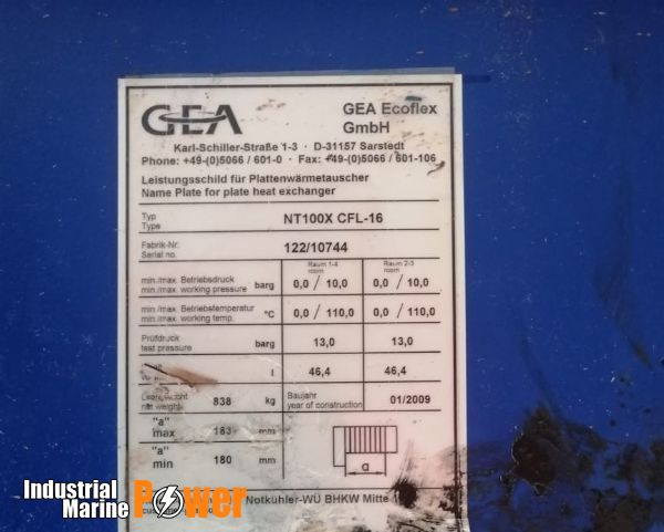
- Plate fouling caused by scale, sludge or biological deposits, resulting in reduced thermal performance and increased pressure drop
- Gasket deterioration caused by age, temperature, chemicals or incorrect compression, resulting in external leakage or cross-leakage paths
- Plate corrosion or pinholing caused by incompatible fluid chemistry, resulting in contamination between circuits
- Blocked channels caused by debris or deposits, resulting in uneven flow and abnormal differential pressure
- Frame or tightening problems caused by incorrect assembly or piping stress, resulting in leakage and uneven gasket loading
- Fouling or scaling increases differential pressure and reduces heat-transfer performance
- Gasket, braze, seal or tube-joint deterioration causes external leakage
- Plate or tube corrosion, erosion or cracking causes internal cross-contamination between fluid circuits
- Blocked strainers or restricted valves reduce flow and produce abnormal inlet-to-outlet temperatures
- Incorrect reassembly, venting or flow distribution after service causes leakage or poor thermal performance
- Heat-transfer surface fouling caused by scale, sludge or biological deposits, resulting in reduced thermal performance and increased pressure drop
- Seal, gasket, braze or tube leakage caused by wear, corrosion or thermal cycling, resulting in external leakage or cross-contamination
- Plate or tube corrosion caused by incompatible fluid chemistry, resulting in pinholes and contamination between circuits
- Blocked flow passages caused by debris or deposits, resulting in uneven flow and abnormal differential pressure
- Frame, cover or connection problems caused by incorrect assembly or piping stress, resulting in leakage and mechanical distortion
- Fouling or scaling increases differential pressure and reduces heat-transfer performance
- Gasket, braze, seal or tube-joint deterioration causes external leakage
- Plate or tube corrosion, erosion or cracking causes internal cross-contamination between fluid circuits
- Blocked strainers or restricted valves reduce flow and produce abnormal inlet-to-outlet temperatures
- Incorrect reassembly, venting or flow distribution after service causes leakage or poor thermal performance
- Heat-transfer surface fouling caused by scale, sludge or biological deposits, resulting in reduced thermal performance and increased pressure drop
- Seal, gasket, braze or tube leakage caused by wear, corrosion or thermal cycling, resulting in external leakage or cross-contamination
- Plate or tube corrosion caused by incompatible fluid chemistry, resulting in pinholes and contamination between circuits
- Blocked flow passages caused by debris or deposits, resulting in uneven flow and abnormal differential pressure
- Frame, cover or connection problems caused by incorrect assembly or piping stress, resulting in leakage and mechanical distortion
- Fouling or scaling increases differential pressure and reduces heat-transfer performance
- Gasket, braze, seal or tube-joint deterioration causes external leakage
- Plate or tube corrosion, erosion or cracking causes internal cross-contamination between fluid circuits
- Blocked strainers or restricted valves reduce flow and produce abnormal inlet-to-outlet temperatures
- Incorrect reassembly, venting or flow distribution after service causes leakage or poor thermal performance
- Heat-transfer surface fouling caused by scale, sludge or biological deposits, resulting in reduced thermal performance and increased pressure drop
- Seal, gasket, braze or tube leakage caused by wear, corrosion or thermal cycling, resulting in external leakage or cross-contamination
- Plate or tube corrosion caused by incompatible fluid chemistry, resulting in pinholes and contamination between circuits
- Blocked flow passages caused by debris or deposits, resulting in uneven flow and abnormal differential pressure
- Frame, cover or connection problems caused by incorrect assembly or piping stress, resulting in leakage and mechanical distortion
- Fouling or scaling increases differential pressure and reduces heat-transfer performance
- Gasket, braze, seal or tube-joint deterioration causes external leakage
- Plate or tube corrosion, erosion or cracking causes internal cross-contamination between fluid circuits
- Blocked strainers or restricted valves reduce flow and produce abnormal inlet-to-outlet temperatures
- Incorrect reassembly, venting or flow distribution after service causes leakage or poor thermal performance
- Heat-transfer surface fouling caused by scale, sludge or biological deposits, resulting in reduced thermal performance and increased pressure drop
- Seal, gasket, braze or tube leakage caused by wear, corrosion or thermal cycling, resulting in external leakage or cross-contamination
- Plate or tube corrosion caused by incompatible fluid chemistry, resulting in pinholes and contamination between circuits
- Blocked flow passages caused by debris or deposits, resulting in uneven flow and abnormal differential pressure
- Frame, cover or connection problems caused by incorrect assembly or piping stress, resulting in leakage and mechanical distortion
- Plate fouling caused by scale, sludge or biological deposits, resulting in reduced thermal performance and increased pressure drop
- Gasket deterioration caused by age, temperature, chemicals or incorrect compression, resulting in external leakage or cross-leakage paths
- Plate corrosion or pinholing caused by incompatible fluid chemistry, resulting in contamination between circuits
- Blocked channels caused by debris or deposits, resulting in uneven flow and abnormal differential pressure
- Frame or tightening problems caused by incorrect assembly or piping stress, resulting in leakage and uneven gasket loading

- Heat-transfer surface fouling caused by scale, sludge or biological deposits, resulting in reduced thermal performance and increased pressure drop
- Seal, gasket, braze or tube leakage caused by wear, corrosion or thermal cycling, resulting in external leakage or cross-contamination
- Plate or tube corrosion caused by incompatible fluid chemistry, resulting in pinholes and contamination between circuits
- Blocked flow passages caused by debris or deposits, resulting in uneven flow and abnormal differential pressure
- Frame, cover or connection problems caused by incorrect assembly or piping stress, resulting in leakage and mechanical distortion
- Fouling or scaling increases differential pressure and reduces heat-transfer performance
- Gasket, braze, seal or tube-joint deterioration causes external leakage
- Plate or tube corrosion, erosion or cracking causes internal cross-contamination between fluid circuits
- Blocked strainers or restricted valves reduce flow and produce abnormal inlet-to-outlet temperatures
- Incorrect reassembly, venting or flow distribution after service causes leakage or poor thermal performance

- Heat-transfer surface fouling caused by scale, sludge or biological deposits, resulting in reduced thermal performance and increased pressure drop
- Seal, gasket, braze or tube leakage caused by wear, corrosion or thermal cycling, resulting in external leakage or cross-contamination
- Plate or tube corrosion caused by incompatible fluid chemistry, resulting in pinholes and contamination between circuits
- Blocked flow passages caused by debris or deposits, resulting in uneven flow and abnormal differential pressure
- Frame, cover or connection problems caused by incorrect assembly or piping stress, resulting in leakage and mechanical distortion
- Fouling or scaling increases differential pressure and reduces heat-transfer performance
- Gasket, braze, seal or tube-joint deterioration causes external leakage
- Plate or tube corrosion, erosion or cracking causes internal cross-contamination between fluid circuits
- Blocked strainers or restricted valves reduce flow and produce abnormal inlet-to-outlet temperatures
- Incorrect reassembly, venting or flow distribution after service causes leakage or poor thermal performance
- Heat-transfer surface fouling caused by scale, sludge or biological deposits, resulting in reduced thermal performance and increased pressure drop
- Seal, gasket, braze or tube leakage caused by wear, corrosion or thermal cycling, resulting in external leakage or cross-contamination
- Plate or tube corrosion caused by incompatible fluid chemistry, resulting in pinholes and contamination between circuits
- Blocked flow passages caused by debris or deposits, resulting in uneven flow and abnormal differential pressure
- Frame, cover or connection problems caused by incorrect assembly or piping stress, resulting in leakage and mechanical distortion
- Fouling or scaling increases differential pressure and reduces heat-transfer performance
- Gasket, braze, seal or tube-joint deterioration causes external leakage
- Plate or tube corrosion, erosion or cracking causes internal cross-contamination between fluid circuits
- Blocked strainers or restricted valves reduce flow and produce abnormal inlet-to-outlet temperatures
- Incorrect reassembly, venting or flow distribution after service causes leakage or poor thermal performance
- Heat-transfer surface fouling caused by scale, sludge or biological deposits, resulting in reduced thermal performance and increased pressure drop
- Seal, gasket, braze or tube leakage caused by wear, corrosion or thermal cycling, resulting in external leakage or cross-contamination
- Plate or tube corrosion caused by incompatible fluid chemistry, resulting in pinholes and contamination between circuits
- Blocked flow passages caused by debris or deposits, resulting in uneven flow and abnormal differential pressure
- Frame, cover or connection problems caused by incorrect assembly or piping stress, resulting in leakage and mechanical distortion
- Fouling or scaling increases differential pressure and reduces heat-transfer performance
- Gasket, braze, seal or tube-joint deterioration causes external leakage
- Plate or tube corrosion, erosion or cracking causes internal cross-contamination between fluid circuits
- Blocked strainers or restricted valves reduce flow and produce abnormal inlet-to-outlet temperatures
- Incorrect reassembly, venting or flow distribution after service causes leakage or poor thermal performance
- Plate fouling caused by scale, sludge or biological deposits, resulting in reduced thermal performance and increased pressure drop
- Gasket deterioration caused by age, temperature, chemicals or incorrect compression, resulting in external leakage or cross-leakage paths
- Plate corrosion or pinholing caused by incompatible fluid chemistry, resulting in contamination between circuits
- Blocked channels caused by debris or deposits, resulting in uneven flow and abnormal differential pressure
- Frame or tightening problems caused by incorrect assembly or piping stress, resulting in leakage and uneven gasket loading
- Heat-transfer surface fouling caused by scale, sludge or biological deposits, resulting in reduced thermal performance and increased pressure drop
- Seal, gasket, braze or tube leakage caused by wear, corrosion or thermal cycling, resulting in external leakage or cross-contamination
- Plate or tube corrosion caused by incompatible fluid chemistry, resulting in pinholes and contamination between circuits
- Blocked flow passages caused by debris or deposits, resulting in uneven flow and abnormal differential pressure
- Frame, cover or connection problems caused by incorrect assembly or piping stress, resulting in leakage and mechanical distortion
- Fouling on heat-transfer surfaces can reduce thermal performance, seen as higher approach temperatures or reduced capacity
- Gasket or tube leakage can mix or release fluids, noticed as pressure loss, contamination or external leakage
- Corrosion or erosion can perforate plates or tubes, detected by leakage or pressure testing
- Blocked passages can raise differential pressure and reduce flow
- Loose clamping or damaged connections can cause leakage during temperature and pressure cycling
- Heat-transfer surface fouling caused by scale, sludge or biological deposits, resulting in reduced thermal performance and increased pressure drop
- Seal, gasket, braze or tube leakage caused by wear, corrosion or thermal cycling, resulting in external leakage or cross-contamination
- Plate or tube corrosion caused by incompatible fluid chemistry, resulting in pinholes and contamination between circuits
- Blocked flow passages caused by debris or deposits, resulting in uneven flow and abnormal differential pressure
- Frame, cover or connection problems caused by incorrect assembly or piping stress, resulting in leakage and mechanical distortion
- Fouling on heat-transfer surfaces can reduce thermal performance, seen as higher approach temperatures or reduced capacity
- Gasket or tube leakage can mix or release fluids, noticed as pressure loss, contamination or external leakage
- Corrosion or erosion can perforate plates or tubes, detected by leakage or pressure testing
- Blocked passages can raise differential pressure and reduce flow
- Loose clamping or damaged connections can cause leakage during temperature and pressure cycling
- Heat-transfer surface fouling caused by scale, sludge or biological deposits, resulting in reduced thermal performance and increased pressure drop
- Seal, gasket, braze or tube leakage caused by wear, corrosion or thermal cycling, resulting in external leakage or cross-contamination
- Plate or tube corrosion caused by incompatible fluid chemistry, resulting in pinholes and contamination between circuits
- Blocked flow passages caused by debris or deposits, resulting in uneven flow and abnormal differential pressure
- Frame, cover or connection problems caused by incorrect assembly or piping stress, resulting in leakage and mechanical distortion
- Fouling on heat-transfer surfaces can reduce thermal performance, seen as higher approach temperatures or reduced capacity
- Gasket or tube leakage can mix or release fluids, noticed as pressure loss, contamination or external leakage
- Corrosion or erosion can perforate plates or tubes, detected by leakage or pressure testing
- Blocked passages can raise differential pressure and reduce flow
- Loose clamping or damaged connections can cause leakage during temperature and pressure cycling
- Heat-transfer surface fouling caused by scale, sludge or biological deposits, resulting in reduced thermal performance and increased pressure drop
- Seal, gasket, braze or tube leakage caused by wear, corrosion or thermal cycling, resulting in external leakage or cross-contamination
- Plate or tube corrosion caused by incompatible fluid chemistry, resulting in pinholes and contamination between circuits
- Blocked flow passages caused by debris or deposits, resulting in uneven flow and abnormal differential pressure
- Frame, cover or connection problems caused by incorrect assembly or piping stress, resulting in leakage and mechanical distortion
- Fouling on heat-transfer surfaces can reduce thermal performance, seen as higher approach temperatures or reduced capacity
- Gasket or tube leakage can mix or release fluids, noticed as pressure loss, contamination or external leakage
- Corrosion or erosion can perforate plates or tubes, detected by leakage or pressure testing
- Blocked passages can raise differential pressure and reduce flow
- Loose clamping or damaged connections can cause leakage during temperature and pressure cycling
- Plate fouling caused by scale, sludge or biological deposits, resulting in reduced thermal performance and increased pressure drop
- Gasket deterioration caused by age, temperature, chemicals or incorrect compression, resulting in external leakage or cross-leakage paths
- Plate corrosion or pinholing caused by incompatible fluid chemistry, resulting in contamination between circuits
- Blocked channels caused by debris or deposits, resulting in uneven flow and abnormal differential pressure
- Frame or tightening problems caused by incorrect assembly or piping stress, resulting in leakage and uneven gasket loading
- Heat-transfer surface fouling caused by scale, sludge or biological deposits, resulting in reduced thermal performance and increased pressure drop
- Seal, gasket, braze or tube leakage caused by wear, corrosion or thermal cycling, resulting in external leakage or cross-contamination
- Plate or tube corrosion caused by incompatible fluid chemistry, resulting in pinholes and contamination between circuits
- Blocked flow passages caused by debris or deposits, resulting in uneven flow and abnormal differential pressure
- Frame, cover or connection problems caused by incorrect assembly or piping stress, resulting in leakage and mechanical distortion
- Heat-transfer surface fouling caused by scale, sludge or biological deposits, resulting in reduced thermal performance and increased pressure drop
- Seal, gasket, braze or tube leakage caused by wear, corrosion or thermal cycling, resulting in external leakage or cross-contamination
- Plate or tube corrosion caused by incompatible fluid chemistry, resulting in pinholes and contamination between circuits
- Blocked flow passages caused by debris or deposits, resulting in uneven flow and abnormal differential pressure
- Frame, cover or connection problems caused by incorrect assembly or piping stress, resulting in leakage and mechanical distortion
- Heat-transfer surface fouling caused by scale, sludge or biological deposits, resulting in reduced thermal performance and increased pressure drop
- Seal, gasket, braze or tube leakage caused by wear, corrosion or thermal cycling, resulting in external leakage or cross-contamination
- Plate or tube corrosion caused by incompatible fluid chemistry, resulting in pinholes and contamination between circuits
- Blocked flow passages caused by debris or deposits, resulting in uneven flow and abnormal differential pressure
- Frame, cover or connection problems caused by incorrect assembly or piping stress, resulting in leakage and mechanical distortion
- Heat-transfer surface fouling caused by scale, sludge or biological deposits, resulting in reduced thermal performance and increased pressure drop
- Seal, gasket, braze or tube leakage caused by wear, corrosion or thermal cycling, resulting in external leakage or cross-contamination
- Plate or tube corrosion caused by incompatible fluid chemistry, resulting in pinholes and contamination between circuits
- Blocked flow passages caused by debris or deposits, resulting in uneven flow and abnormal differential pressure
- Frame, cover or connection problems caused by incorrect assembly or piping stress, resulting in leakage and mechanical distortion
- Plate fouling caused by scale, sludge or biological deposits, resulting in reduced thermal performance and increased pressure drop
- Gasket deterioration caused by age, temperature, chemicals or incorrect compression, resulting in external leakage or cross-leakage paths
- Plate corrosion or pinholing caused by incompatible fluid chemistry, resulting in contamination between circuits
- Blocked channels caused by debris or deposits, resulting in uneven flow and abnormal differential pressure
- Frame or tightening problems caused by incorrect assembly or piping stress, resulting in leakage and uneven gasket loading
- Fouling or scaling increases differential pressure and reduces heat-transfer performance
- Gasket, braze, seal or tube-joint deterioration causes external leakage
- Plate or tube corrosion, erosion or cracking causes internal cross-contamination between fluid circuits
- Blocked strainers or restricted valves reduce flow and produce abnormal inlet-to-outlet temperatures
- Incorrect reassembly, venting or flow distribution after service causes leakage or poor thermal performance
- Fouling or scaling increases differential pressure and reduces heat-transfer performance
- Gasket, braze, seal or tube-joint deterioration causes external leakage
- Plate or tube corrosion, erosion or cracking causes internal cross-contamination between fluid circuits
- Blocked strainers or restricted valves reduce flow and produce abnormal inlet-to-outlet temperatures
- Incorrect reassembly, venting or flow distribution after service causes leakage or poor thermal performance
- Fouling or scaling increases differential pressure and reduces heat-transfer performance
- Gasket, braze, seal or tube-joint deterioration causes external leakage
- Plate or tube corrosion, erosion or cracking causes internal cross-contamination between fluid circuits
- Blocked strainers or restricted valves reduce flow and produce abnormal inlet-to-outlet temperatures
- Incorrect reassembly, venting or flow distribution after service causes leakage or poor thermal performance
- Fouling or scaling increases differential pressure and reduces heat-transfer performance
- Gasket, braze, seal or tube-joint deterioration causes external leakage
- Plate or tube corrosion, erosion or cracking causes internal cross-contamination between fluid circuits
- Blocked strainers or restricted valves reduce flow and produce abnormal inlet-to-outlet temperatures
- Incorrect reassembly, venting or flow distribution after service causes leakage or poor thermal performance
- Fouling or scaling increases differential pressure and reduces heat-transfer performance
- Gasket, braze, seal or tube-joint deterioration causes external leakage
- Plate or tube corrosion, erosion or cracking causes internal cross-contamination between fluid circuits
- Blocked strainers or restricted valves reduce flow and produce abnormal inlet-to-outlet temperatures
- Incorrect reassembly, venting or flow distribution after service causes leakage or poor thermal performance
- Fouling or scaling increases differential pressure and reduces heat-transfer performance
- Gasket, braze, seal or tube-joint deterioration causes external leakage
- Plate or tube corrosion, erosion or cracking causes internal cross-contamination between fluid circuits
- Blocked strainers or restricted valves reduce flow and produce abnormal inlet-to-outlet temperatures
- Incorrect reassembly, venting or flow distribution after service causes leakage or poor thermal performance

- Plate fouling caused by scale, sludge or biological deposits, resulting in reduced thermal performance and increased pressure drop
- Gasket deterioration caused by age, temperature, chemicals or incorrect compression, resulting in external leakage or cross-leakage paths
- Plate corrosion or pinholing caused by incompatible fluid chemistry, resulting in contamination between circuits
- Blocked channels caused by debris or deposits, resulting in uneven flow and abnormal differential pressure
- Frame or tightening problems caused by incorrect assembly or piping stress, resulting in leakage and uneven gasket loading
- Plate/tube fouling from scale, sludge or marine growth, typically indicated by reduced temperature approach, high pressure drop or insufficient cooling/heating
- Gasket or braze leakage from ageing, chemical attack or thermal stress, typically indicated by external leakage or cross-contamination
- Corrosion/erosion of heat-transfer surfaces, typically indicated by fluid contamination, pinhole leakage or loss of performance
- Flow blockage or air locking, typically indicated by unstable temperatures or reduced flow
- Incorrect tightening or mechanical distortion after maintenance, typically indicated by gasket leakage or uneven plate compression
- Plate/tube fouling from scale, sludge or marine growth, typically indicated by reduced temperature approach, high pressure drop or insufficient cooling/heating
- Gasket or braze leakage from ageing, chemical attack or thermal stress, typically indicated by external leakage or cross-contamination
- Corrosion/erosion of heat-transfer surfaces, typically indicated by fluid contamination, pinhole leakage or loss of performance
- Flow blockage or air locking, typically indicated by unstable temperatures or reduced flow
- Incorrect tightening or mechanical distortion after maintenance, typically indicated by gasket leakage or uneven plate compression
- Plate/tube fouling from scale, sludge or marine growth, typically indicated by reduced temperature approach, high pressure drop or insufficient cooling/heating
- Gasket or braze leakage from ageing, chemical attack or thermal stress, typically indicated by external leakage or cross-contamination
- Corrosion/erosion of heat-transfer surfaces, typically indicated by fluid contamination, pinhole leakage or loss of performance
- Flow blockage or air locking, typically indicated by unstable temperatures or reduced flow
- Incorrect tightening or mechanical distortion after maintenance, typically indicated by gasket leakage or uneven plate compression

- Plate fouling caused by scale, sludge or biological deposits, resulting in reduced thermal performance and increased pressure drop
- Gasket deterioration caused by age, temperature, chemicals or incorrect compression, resulting in external leakage or cross-leakage paths
- Plate corrosion or pinholing caused by incompatible fluid chemistry, resulting in contamination between circuits
- Blocked channels caused by debris or deposits, resulting in uneven flow and abnormal differential pressure
- Frame or tightening problems caused by incorrect assembly or piping stress, resulting in leakage and uneven gasket loading
- Fouling or scaling increases differential pressure and reduces heat-transfer performance
- Gasket, braze, seal or tube-joint deterioration causes external leakage
- Plate or tube corrosion, erosion or cracking causes internal cross-contamination between fluid circuits
- Blocked strainers or restricted valves reduce flow and produce abnormal inlet-to-outlet temperatures
- Incorrect reassembly, venting or flow distribution after service causes leakage or poor thermal performance
- Heat-transfer surface fouling caused by scale, sludge or biological deposits, resulting in reduced thermal performance and increased pressure drop
- Seal, gasket, braze or tube leakage caused by wear, corrosion or thermal cycling, resulting in external leakage or cross-contamination
- Plate or tube corrosion caused by incompatible fluid chemistry, resulting in pinholes and contamination between circuits
- Blocked flow passages caused by debris or deposits, resulting in uneven flow and abnormal differential pressure
- Frame, cover or connection problems caused by incorrect assembly or piping stress, resulting in leakage and mechanical distortion
- Fouling or scaling increases differential pressure and reduces heat-transfer performance
- Gasket, braze, seal or tube-joint deterioration causes external leakage
- Plate or tube corrosion, erosion or cracking causes internal cross-contamination between fluid circuits
- Blocked strainers or restricted valves reduce flow and produce abnormal inlet-to-outlet temperatures
- Incorrect reassembly, venting or flow distribution after service causes leakage or poor thermal performance
- Heat-transfer surface fouling caused by scale, sludge or biological deposits, resulting in reduced thermal performance and increased pressure drop
- Seal, gasket, braze or tube leakage caused by wear, corrosion or thermal cycling, resulting in external leakage or cross-contamination
- Plate or tube corrosion caused by incompatible fluid chemistry, resulting in pinholes and contamination between circuits
- Blocked flow passages caused by debris or deposits, resulting in uneven flow and abnormal differential pressure
- Frame, cover or connection problems caused by incorrect assembly or piping stress, resulting in leakage and mechanical distortion

- Fouling or scaling increases differential pressure and reduces heat-transfer performance
- Gasket, braze, seal or tube-joint deterioration causes external leakage
- Plate or tube corrosion, erosion or cracking causes internal cross-contamination between fluid circuits
- Blocked strainers or restricted valves reduce flow and produce abnormal inlet-to-outlet temperatures
- Incorrect reassembly, venting or flow distribution after service causes leakage or poor thermal performance
- Heat-transfer surface fouling caused by scale, sludge or biological deposits, resulting in reduced thermal performance and increased pressure drop
- Seal, gasket, braze or tube leakage caused by wear, corrosion or thermal cycling, resulting in external leakage or cross-contamination
- Plate or tube corrosion caused by incompatible fluid chemistry, resulting in pinholes and contamination between circuits
- Blocked flow passages caused by debris or deposits, resulting in uneven flow and abnormal differential pressure
- Frame, cover or connection problems caused by incorrect assembly or piping stress, resulting in leakage and mechanical distortion

- Fouling or scaling increases differential pressure and reduces heat-transfer performance
- Gasket, braze, seal or tube-joint deterioration causes external leakage
- Plate or tube corrosion, erosion or cracking causes internal cross-contamination between fluid circuits
- Blocked strainers or restricted valves reduce flow and produce abnormal inlet-to-outlet temperatures
- Incorrect reassembly, venting or flow distribution after service causes leakage or poor thermal performance
- Heat-transfer surface fouling caused by scale, sludge or biological deposits, resulting in reduced thermal performance and increased pressure drop
- Seal, gasket, braze or tube leakage caused by wear, corrosion or thermal cycling, resulting in external leakage or cross-contamination
- Plate or tube corrosion caused by incompatible fluid chemistry, resulting in pinholes and contamination between circuits
- Blocked flow passages caused by debris or deposits, resulting in uneven flow and abnormal differential pressure
- Frame, cover or connection problems caused by incorrect assembly or piping stress, resulting in leakage and mechanical distortion

- Plate fouling caused by scale, sludge or biological deposits, resulting in reduced thermal performance and increased pressure drop
- Gasket deterioration caused by age, temperature, chemicals or incorrect compression, resulting in external leakage or cross-leakage paths
- Plate corrosion or pinholing caused by incompatible fluid chemistry, resulting in contamination between circuits
- Blocked channels caused by debris or deposits, resulting in uneven flow and abnormal differential pressure
- Frame or tightening problems caused by incorrect assembly or piping stress, resulting in leakage and uneven gasket loading

- Fouling or scaling increases differential pressure and reduces heat-transfer performance
- Gasket, braze, seal or tube-joint deterioration causes external leakage
- Plate or tube corrosion, erosion or cracking causes internal cross-contamination between fluid circuits
- Blocked strainers or restricted valves reduce flow and produce abnormal inlet-to-outlet temperatures
- Incorrect reassembly, venting or flow distribution after service causes leakage or poor thermal performance
- Heat-transfer surface fouling caused by scale, sludge or biological deposits, resulting in reduced thermal performance and increased pressure drop
- Seal, gasket, braze or tube leakage caused by wear, corrosion or thermal cycling, resulting in external leakage or cross-contamination
- Plate or tube corrosion caused by incompatible fluid chemistry, resulting in pinholes and contamination between circuits
- Blocked flow passages caused by debris or deposits, resulting in uneven flow and abnormal differential pressure
- Frame, cover or connection problems caused by incorrect assembly or piping stress, resulting in leakage and mechanical distortion
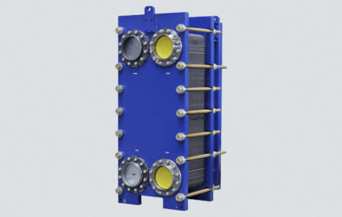
- Fouling or scaling increases differential pressure and reduces heat-transfer performance
- Gasket, braze, seal or tube-joint deterioration causes external leakage
- Plate or tube corrosion, erosion or cracking causes internal cross-contamination between fluid circuits
- Blocked strainers or restricted valves reduce flow and produce abnormal inlet-to-outlet temperatures
- Incorrect reassembly, venting or flow distribution after service causes leakage or poor thermal performance
- Heat-transfer surface fouling caused by scale, sludge or biological deposits, resulting in reduced thermal performance and increased pressure drop
- Seal, gasket, braze or tube leakage caused by wear, corrosion or thermal cycling, resulting in external leakage or cross-contamination
- Plate or tube corrosion caused by incompatible fluid chemistry, resulting in pinholes and contamination between circuits
- Blocked flow passages caused by debris or deposits, resulting in uneven flow and abnormal differential pressure
- Frame, cover or connection problems caused by incorrect assembly or piping stress, resulting in leakage and mechanical distortion
- Fouling or scaling increases differential pressure and reduces heat-transfer performance
- Gasket, braze, seal or tube-joint deterioration causes external leakage
- Plate or tube corrosion, erosion or cracking causes internal cross-contamination between fluid circuits
- Blocked strainers or restricted valves reduce flow and produce abnormal inlet-to-outlet temperatures
- Incorrect reassembly, venting or flow distribution after service causes leakage or poor thermal performance
- Heat-transfer surface fouling caused by scale, sludge or biological deposits, resulting in reduced thermal performance and increased pressure drop
- Seal, gasket, braze or tube leakage caused by wear, corrosion or thermal cycling, resulting in external leakage or cross-contamination
- Plate or tube corrosion caused by incompatible fluid chemistry, resulting in pinholes and contamination between circuits
- Blocked flow passages caused by debris or deposits, resulting in uneven flow and abnormal differential pressure
- Frame, cover or connection problems caused by incorrect assembly or piping stress, resulting in leakage and mechanical distortion
Sondex
58- Plate/tube fouling from scale, sludge or marine growth, typically indicated by reduced temperature approach, high pressure drop or insufficient cooling/heating
- Gasket or braze leakage from ageing, chemical attack or thermal stress, typically indicated by external leakage or cross-contamination
- Corrosion/erosion of heat-transfer surfaces, typically indicated by fluid contamination, pinhole leakage or loss of performance
- Flow blockage or air locking, typically indicated by unstable temperatures or reduced flow
- Incorrect tightening or mechanical distortion after maintenance, typically indicated by gasket leakage or uneven plate compression
- Plate fouling caused by scale, sludge or biological deposits, resulting in reduced thermal performance and increased pressure drop
- Gasket deterioration caused by age, temperature, chemicals or incorrect compression, resulting in external leakage or cross-leakage paths
- Plate corrosion or pinholing caused by incompatible fluid chemistry, resulting in contamination between circuits
- Blocked channels caused by debris or deposits, resulting in uneven flow and abnormal differential pressure
- Frame or tightening problems caused by incorrect assembly or piping stress, resulting in leakage and uneven gasket loading
- Fouling on the heat-transfer surfaces from scale, sludge, biological growth, or oil contamination reduces thermal performance and appears as rising outlet temperature or reduced temperature approach
- Gasket, seal, tube, or plate leakage caused by ageing, corrosion, or mechanical damage can allow external leakage or cross-contamination between circuits
- Restricted flow from debris or deposits raises differential pressure and can reduce downstream flow
- Corrosion or erosion of wetted surfaces caused by unsuitable water chemistry, velocity, or material attack can produce pinhole leakage and contamination
- Loose covers, plate packs, or connections after maintenance can cause leakage, unstable temperatures, or loss of system pressure
- Fouling or deposit build-up caused by poor combustion, contaminated fluid or exhaust soot can reduce heat transfer or flow and produce higher temperatures or loss of capacity
- Leakage from tubes, gaskets, seals or casing caused by corrosion, thermal cycling or erosion can appear as fluid loss, pressure decay or cross-contamination
- Burner, ignition or fuel-control faults where combustion is used can cause flame failure, unstable firing, smoke or shutdown alarms
- Fan, pump or actuator faults caused by mechanical wear or electrical problems can reduce circulation, airflow or treatment effectiveness
- Sensor, control or safety-interlock faults caused by drift, wiring defects or contamination can trigger nuisance trips or allow unstable operation
- Fouling or deposit build-up caused by poor combustion, contaminated fluid or exhaust soot can reduce heat transfer or flow and produce higher temperatures or loss of capacity
- Leakage from tubes, gaskets, seals or casing caused by corrosion, thermal cycling or erosion can appear as fluid loss, pressure decay or cross-contamination
- Burner, ignition or fuel-control faults where combustion is used can cause flame failure, unstable firing, smoke or shutdown alarms
- Fan, pump or actuator faults caused by mechanical wear or electrical problems can reduce circulation, airflow or treatment effectiveness
- Sensor, control or safety-interlock faults caused by drift, wiring defects or contamination can trigger nuisance trips or allow unstable operation
- Fouling or deposit build-up caused by poor combustion, contaminated fluid or exhaust soot can reduce heat transfer or flow and produce higher temperatures or loss of capacity
- Leakage from tubes, gaskets, seals or casing caused by corrosion, thermal cycling or erosion can appear as fluid loss, pressure decay or cross-contamination
- Burner, ignition or fuel-control faults where combustion is used can cause flame failure, unstable firing, smoke or shutdown alarms
- Fan, pump or actuator faults caused by mechanical wear or electrical problems can reduce circulation, airflow or treatment effectiveness
- Sensor, control or safety-interlock faults caused by drift, wiring defects or contamination can trigger nuisance trips or allow unstable operation
- Fouling on heat-transfer surfaces from scale, sludge, biological growth, or oil contamination reduces thermal performance and appears as rising outlet temperature
- Gasket, seal, tube, or plate leakage from ageing, corrosion, or mechanical damage causes external leakage or cross-contamination
- Restricted flow from debris or deposits raises pressure drop and reduces downstream flow
- Corrosion or erosion of wetted surfaces from unsuitable water chemistry, velocity, or material attack produces pinhole leakage
- Loose covers, plate packs, or connections after maintenance cause leakage, unstable temperatures, or loss of system pressure
- Fouling on heat-transfer surfaces from scale, sludge, biological growth, or oil contamination reduces thermal performance and appears as rising outlet temperature
- Gasket, seal, tube, or plate leakage from ageing, corrosion, or mechanical damage causes external leakage or cross-contamination
- Restricted flow from debris or deposits raises pressure drop and reduces downstream flow
- Corrosion or erosion of wetted surfaces from unsuitable water chemistry, velocity, or material attack produces pinhole leakage
- Loose covers, plate packs, or connections after maintenance cause leakage, unstable temperatures, or loss of system pressure
- Plate/tube fouling from scale, sludge or marine growth, typically indicated by reduced temperature approach, high pressure drop or insufficient cooling/heating
- Gasket or braze leakage from ageing, chemical attack or thermal stress, typically indicated by external leakage or cross-contamination
- Corrosion/erosion of heat-transfer surfaces, typically indicated by fluid contamination, pinhole leakage or loss of performance
- Flow blockage or air locking, typically indicated by unstable temperatures or reduced flow
- Incorrect tightening or mechanical distortion after maintenance, typically indicated by gasket leakage or uneven plate compression
- Plate fouling or scaling raises differential pressure and reduces heat-transfer performance
- Gasket ageing, displacement or chemical attack causes external leakage at the plate pack
- Plate corrosion, erosion or cracking causes internal cross-contamination between fluid circuits
- Incorrect plate sequence or compression after overhaul causes immediate leakage or poor thermal performance
- Blocked upstream strainers reduce flow and create abnormal inlet-to-outlet temperatures
- Fouling or scaling increases differential pressure and reduces heat-transfer performance
- Gasket, braze, seal or tube-joint deterioration causes external leakage
- Plate or tube corrosion, erosion or cracking causes internal cross-contamination between fluid circuits
- Blocked strainers or restricted valves reduce flow and produce abnormal inlet-to-outlet temperatures
- Incorrect reassembly, venting or flow distribution after service causes leakage or poor thermal performance
- Fouling or scaling increases differential pressure and reduces heat-transfer performance
- Gasket, braze, seal or tube-joint deterioration causes external leakage
- Plate or tube corrosion, erosion or cracking causes internal cross-contamination between fluid circuits
- Blocked strainers or restricted valves reduce flow and produce abnormal inlet-to-outlet temperatures
- Incorrect reassembly, venting or flow distribution after service causes leakage or poor thermal performance
- Plate-channel fouling caused by scale, sludge or biological deposits, resulting in reduced thermal performance and increased pressure drop
- Gasket, braze or connection leakage caused by wear, corrosion or thermal cycling, resulting in external leakage or cross-contamination
- Plate corrosion caused by incompatible fluid chemistry, resulting in pinholes and contamination between circuits
- Blocked channels caused by debris or deposits, resulting in uneven flow and abnormal differential pressure
- Frame or connection problems caused by incorrect assembly or piping stress, resulting in leakage and mechanical distortion
- Plate-channel fouling caused by scale, sludge or biological deposits, resulting in reduced thermal performance and increased pressure drop
- Gasket, braze or connection leakage caused by wear, corrosion or thermal cycling, resulting in external leakage or cross-contamination
- Plate corrosion caused by incompatible fluid chemistry, resulting in pinholes and contamination between circuits
- Blocked channels caused by debris or deposits, resulting in uneven flow and abnormal differential pressure
- Frame or connection problems caused by incorrect assembly or piping stress, resulting in leakage and mechanical distortion

- Plate-channel fouling caused by scale, sludge or biological deposits, resulting in reduced thermal performance and increased pressure drop
- Gasket, braze or connection leakage caused by wear, corrosion or thermal cycling, resulting in external leakage or cross-contamination
- Plate corrosion caused by incompatible fluid chemistry, resulting in pinholes and contamination between circuits
- Blocked channels caused by debris or deposits, resulting in uneven flow and abnormal differential pressure
- Frame or connection problems caused by incorrect assembly or piping stress, resulting in leakage and mechanical distortion
- Plate-channel fouling caused by scale, sludge or biological deposits, resulting in reduced thermal performance and increased pressure drop
- Gasket, braze or connection leakage caused by wear, corrosion or thermal cycling, resulting in external leakage or cross-contamination
- Plate corrosion caused by incompatible fluid chemistry, resulting in pinholes and contamination between circuits
- Blocked channels caused by debris or deposits, resulting in uneven flow and abnormal differential pressure
- Frame or connection problems caused by incorrect assembly or piping stress, resulting in leakage and mechanical distortion
- Plate fouling or scaling raises differential pressure and reduces heat-transfer performance
- Gasket ageing, displacement or chemical attack causes external leakage at the plate pack
- Plate corrosion, erosion or cracking causes internal cross-contamination between fluid circuits
- Incorrect plate sequence or compression after overhaul causes immediate leakage or poor thermal performance
- Blocked upstream strainers reduce flow and create abnormal inlet-to-outlet temperatures
- Plate-channel fouling caused by scale, sludge or biological deposits, resulting in reduced thermal performance and increased pressure drop
- Gasket, braze or connection leakage caused by wear, corrosion or thermal cycling, resulting in external leakage or cross-contamination
- Plate corrosion caused by incompatible fluid chemistry, resulting in pinholes and contamination between circuits
- Blocked channels caused by debris or deposits, resulting in uneven flow and abnormal differential pressure
- Frame or connection problems caused by incorrect assembly or piping stress, resulting in leakage and mechanical distortion
- Plate-channel fouling caused by scale, sludge or biological deposits, resulting in reduced thermal performance and increased pressure drop
- Gasket, braze or connection leakage caused by wear, corrosion or thermal cycling, resulting in external leakage or cross-contamination
- Plate corrosion caused by incompatible fluid chemistry, resulting in pinholes and contamination between circuits
- Blocked channels caused by debris or deposits, resulting in uneven flow and abnormal differential pressure
- Frame or connection problems caused by incorrect assembly or piping stress, resulting in leakage and mechanical distortion
- Plate-channel fouling caused by scale, sludge or biological deposits, resulting in reduced thermal performance and increased pressure drop
- Gasket, braze or connection leakage caused by wear, corrosion or thermal cycling, resulting in external leakage or cross-contamination
- Plate corrosion caused by incompatible fluid chemistry, resulting in pinholes and contamination between circuits
- Blocked channels caused by debris or deposits, resulting in uneven flow and abnormal differential pressure
- Frame or connection problems caused by incorrect assembly or piping stress, resulting in leakage and mechanical distortion
- Plate-channel fouling caused by scale, sludge or biological deposits, resulting in reduced thermal performance and increased pressure drop
- Gasket, braze or connection leakage caused by wear, corrosion or thermal cycling, resulting in external leakage or cross-contamination
- Plate corrosion caused by incompatible fluid chemistry, resulting in pinholes and contamination between circuits
- Blocked channels caused by debris or deposits, resulting in uneven flow and abnormal differential pressure
- Frame or connection problems caused by incorrect assembly or piping stress, resulting in leakage and mechanical distortion
- Plate-channel fouling caused by scale, sludge or biological deposits, resulting in reduced thermal performance and increased pressure drop
- Gasket, braze or connection leakage caused by wear, corrosion or thermal cycling, resulting in external leakage or cross-contamination
- Plate corrosion caused by incompatible fluid chemistry, resulting in pinholes and contamination between circuits
- Blocked channels caused by debris or deposits, resulting in uneven flow and abnormal differential pressure
- Frame or connection problems caused by incorrect assembly or piping stress, resulting in leakage and mechanical distortion
- Plate-channel fouling caused by scale, sludge or biological deposits, resulting in reduced thermal performance and increased pressure drop
- Gasket, braze or connection leakage caused by wear, corrosion or thermal cycling, resulting in external leakage or cross-contamination
- Plate corrosion caused by incompatible fluid chemistry, resulting in pinholes and contamination between circuits
- Blocked channels caused by debris or deposits, resulting in uneven flow and abnormal differential pressure
- Frame or connection problems caused by incorrect assembly or piping stress, resulting in leakage and mechanical distortion
- Plate fouling or scale reduces heat transfer, noticed as poor outlet temperatures and increasing temperature approach
- Gasket ageing or incorrect plate compression causes external leakage between plate edges
- Plate perforation can allow cross-contamination, noticed as unexpected level, pressure or fluid-quality changes
- Blocked passages increase pressure drop and reduce circulation through the exchanger
- Corrosion or erosion damages plates and can lead to repeated leakage
- Heat-transfer surface fouling caused by scale, sludge or biological deposits, resulting in reduced thermal performance and increased pressure drop
- Seal, gasket, braze or tube leakage caused by wear, corrosion or thermal cycling, resulting in external leakage or cross-contamination
- Plate or tube corrosion caused by incompatible fluid chemistry, resulting in pinholes and contamination between circuits
- Blocked flow passages caused by debris or deposits, resulting in uneven flow and abnormal differential pressure
- Frame, cover or connection problems caused by incorrect assembly or piping stress, resulting in leakage and mechanical distortion
- Plate-channel fouling caused by scale, sludge or biological deposits, resulting in reduced thermal performance and increased pressure drop
- Gasket, braze or connection leakage caused by wear, corrosion or thermal cycling, resulting in external leakage or cross-contamination
- Plate corrosion caused by incompatible fluid chemistry, resulting in pinholes and contamination between circuits
- Blocked channels caused by debris or deposits, resulting in uneven flow and abnormal differential pressure
- Frame or connection problems caused by incorrect assembly or piping stress, resulting in leakage and mechanical distortion
- Heat-transfer surface fouling caused by scale, sludge or biological deposits, resulting in reduced thermal performance and increased pressure drop
- Seal, gasket, braze or tube leakage caused by wear, corrosion or thermal cycling, resulting in external leakage or cross-contamination
- Plate or tube corrosion caused by incompatible fluid chemistry, resulting in pinholes and contamination between circuits
- Blocked flow passages caused by debris or deposits, resulting in uneven flow and abnormal differential pressure
- Frame, cover or connection problems caused by incorrect assembly or piping stress, resulting in leakage and mechanical distortion
- Plate-channel fouling caused by scale, sludge or biological deposits, resulting in reduced thermal performance and increased pressure drop
- Gasket, braze or connection leakage caused by wear, corrosion or thermal cycling, resulting in external leakage or cross-contamination
- Plate corrosion caused by incompatible fluid chemistry, resulting in pinholes and contamination between circuits
- Blocked channels caused by debris or deposits, resulting in uneven flow and abnormal differential pressure
- Frame or connection problems caused by incorrect assembly or piping stress, resulting in leakage and mechanical distortion
- Fouling on heat-transfer surfaces can reduce thermal performance, seen as higher approach temperatures or reduced capacity
- Gasket or tube leakage can mix or release fluids, noticed as pressure loss, contamination or external leakage
- Corrosion or erosion can perforate plates or tubes, detected by leakage or pressure testing
- Blocked passages can raise differential pressure and reduce flow
- Loose clamping or damaged connections can cause leakage during temperature and pressure cycling
- Plate-channel fouling caused by scale, sludge or biological deposits, resulting in reduced thermal performance and increased pressure drop
- Gasket, braze or connection leakage caused by wear, corrosion or thermal cycling, resulting in external leakage or cross-contamination
- Plate corrosion caused by incompatible fluid chemistry, resulting in pinholes and contamination between circuits
- Blocked channels caused by debris or deposits, resulting in uneven flow and abnormal differential pressure
- Frame or connection problems caused by incorrect assembly or piping stress, resulting in leakage and mechanical distortion
- Plate fouling or scale reduces heat transfer, noticed as poor outlet temperatures and increasing temperature approach
- Gasket ageing or incorrect plate compression causes external leakage between plate edges
- Plate perforation can allow cross-contamination, noticed as unexpected level, pressure or fluid-quality changes
- Blocked passages increase pressure drop and reduce circulation through the exchanger
- Corrosion or erosion damages plates and can lead to repeated leakage
- Heat-transfer surface fouling caused by scale, sludge or biological deposits, resulting in reduced thermal performance and increased pressure drop
- Seal, gasket, braze or tube leakage caused by wear, corrosion or thermal cycling, resulting in external leakage or cross-contamination
- Plate or tube corrosion caused by incompatible fluid chemistry, resulting in pinholes and contamination between circuits
- Blocked flow passages caused by debris or deposits, resulting in uneven flow and abnormal differential pressure
- Frame, cover or connection problems caused by incorrect assembly or piping stress, resulting in leakage and mechanical distortion
- Fouling on heat-transfer surfaces can reduce thermal performance, seen as higher approach temperatures or reduced capacity
- Gasket or tube leakage can mix or release fluids, noticed as pressure loss, contamination or external leakage
- Corrosion or erosion can perforate plates or tubes, detected by leakage or pressure testing
- Blocked passages can raise differential pressure and reduce flow
- Loose clamping or damaged connections can cause leakage during temperature and pressure cycling
- Fouling on heat-transfer surfaces can reduce thermal performance, seen as higher approach temperatures or reduced capacity
- Gasket or tube leakage can mix or release fluids, noticed as pressure loss, contamination or external leakage
- Corrosion or erosion can perforate plates or tubes, detected by leakage or pressure testing
- Blocked passages can raise differential pressure and reduce flow
- Loose clamping or damaged connections can cause leakage during temperature and pressure cycling
- Plate fouling or scale reduces heat transfer, noticed as poor outlet temperatures and increasing temperature approach
- Gasket ageing or incorrect plate compression causes external leakage between plate edges
- Plate perforation can allow cross-contamination, noticed as unexpected level, pressure or fluid-quality changes
- Blocked passages increase pressure drop and reduce circulation through the exchanger
- Corrosion or erosion damages plates and can lead to repeated leakage
- Heat-transfer surface fouling caused by scale, sludge or biological deposits, resulting in reduced thermal performance and increased pressure drop
- Seal, gasket, braze or tube leakage caused by wear, corrosion or thermal cycling, resulting in external leakage or cross-contamination
- Plate or tube corrosion caused by incompatible fluid chemistry, resulting in pinholes and contamination between circuits
- Blocked flow passages caused by debris or deposits, resulting in uneven flow and abnormal differential pressure
- Frame, cover or connection problems caused by incorrect assembly or piping stress, resulting in leakage and mechanical distortion
- Fouling on heat-transfer surfaces can reduce thermal performance, seen as higher approach temperatures or reduced capacity
- Gasket or tube leakage can mix or release fluids, noticed as pressure loss, contamination or external leakage
- Corrosion or erosion can perforate plates or tubes, detected by leakage or pressure testing
- Blocked passages can raise differential pressure and reduce flow
- Loose clamping or damaged connections can cause leakage during temperature and pressure cycling
- Fouling on heat-transfer surfaces can reduce thermal performance, seen as higher approach temperatures or reduced capacity
- Gasket or tube leakage can mix or release fluids, noticed as pressure loss, contamination or external leakage
- Corrosion or erosion can perforate plates or tubes, detected by leakage or pressure testing
- Blocked passages can raise differential pressure and reduce flow
- Loose clamping or damaged connections can cause leakage during temperature and pressure cycling
- Fouling on heat-transfer surfaces can reduce thermal performance, seen as higher approach temperatures or reduced capacity
- Gasket or tube leakage can mix or release fluids, noticed as pressure loss, contamination or external leakage
- Corrosion or erosion can perforate plates or tubes, detected by leakage or pressure testing
- Blocked passages can raise differential pressure and reduce flow
- Loose clamping or damaged connections can cause leakage during temperature and pressure cycling
- Fouling on heat-transfer surfaces can reduce thermal performance, seen as higher approach temperatures or reduced capacity
- Gasket or tube leakage can mix or release fluids, noticed as pressure loss, contamination or external leakage
- Corrosion or erosion can perforate plates or tubes, detected by leakage or pressure testing
- Blocked passages can raise differential pressure and reduce flow
- Loose clamping or damaged connections can cause leakage during temperature and pressure cycling
- Fouling on heat-transfer surfaces can reduce thermal performance, seen as higher approach temperatures or reduced capacity
- Gasket or tube leakage can mix or release fluids, noticed as pressure loss, contamination or external leakage
- Corrosion or erosion can perforate plates or tubes, detected by leakage or pressure testing
- Blocked passages can raise differential pressure and reduce flow
- Loose clamping or damaged connections can cause leakage during temperature and pressure cycling
- Fouling on heat-transfer surfaces can reduce thermal performance, seen as higher approach temperatures or reduced capacity
- Gasket or tube leakage can mix or release fluids, noticed as pressure loss, contamination or external leakage
- Corrosion or erosion can perforate plates or tubes, detected by leakage or pressure testing
- Blocked passages can raise differential pressure and reduce flow
- Loose clamping or damaged connections can cause leakage during temperature and pressure cycling
- Fouling on heat-transfer surfaces can reduce thermal performance, seen as higher approach temperatures or reduced capacity
- Gasket or tube leakage can mix or release fluids, noticed as pressure loss, contamination or external leakage
- Corrosion or erosion can perforate plates or tubes, detected by leakage or pressure testing
- Blocked passages can raise differential pressure and reduce flow
- Loose clamping or damaged connections can cause leakage during temperature and pressure cycling
- Plate fouling or scale reduces heat transfer, noticed as poor outlet temperatures and increasing temperature approach
- Gasket ageing or incorrect plate compression causes external leakage between plate edges
- Plate perforation can allow cross-contamination, noticed as unexpected level, pressure or fluid-quality changes
- Blocked passages increase pressure drop and reduce circulation through the exchanger
- Corrosion or erosion damages plates and can lead to repeated leakage
- Fouling on heat-transfer surfaces can reduce thermal performance, seen as higher approach temperatures or reduced capacity
- Gasket or tube leakage can mix or release fluids, noticed as pressure loss, contamination or external leakage
- Corrosion or erosion can perforate plates or tubes, detected by leakage or pressure testing
- Blocked passages can raise differential pressure and reduce flow
- Loose clamping or damaged connections can cause leakage during temperature and pressure cycling
- Fouling on heat-transfer surfaces can reduce thermal performance, seen as higher approach temperatures or reduced capacity
- Gasket or tube leakage can mix or release fluids, noticed as pressure loss, contamination or external leakage
- Corrosion or erosion can perforate plates or tubes, detected by leakage or pressure testing
- Blocked passages can raise differential pressure and reduce flow
- Loose clamping or damaged connections can cause leakage during temperature and pressure cycling
- Fouling on heat-transfer surfaces can reduce thermal performance, seen as higher approach temperatures or reduced capacity
- Gasket or tube leakage can mix or release fluids, noticed as pressure loss, contamination or external leakage
- Corrosion or erosion can perforate plates or tubes, detected by leakage or pressure testing
- Blocked passages can raise differential pressure and reduce flow
- Loose clamping or damaged connections can cause leakage during temperature and pressure cycling
- Fouling on heat-transfer surfaces can reduce thermal performance, seen as higher approach temperatures or reduced capacity
- Gasket or tube leakage can mix or release fluids, noticed as pressure loss, contamination or external leakage
- Corrosion or erosion can perforate plates or tubes, detected by leakage or pressure testing
- Blocked passages can raise differential pressure and reduce flow
- Loose clamping or damaged connections can cause leakage during temperature and pressure cycling
- Plate fouling or scale reduces heat transfer, noticed as poor outlet temperatures and increasing temperature approach
- Gasket ageing or incorrect plate compression causes external leakage between plate edges
- Plate perforation can allow cross-contamination, noticed as unexpected level, pressure or fluid-quality changes
- Blocked passages increase pressure drop and reduce circulation through the exchanger
- Corrosion or erosion damages plates and can lead to repeated leakage
- Fouling on heat-transfer surfaces can reduce thermal performance, seen as higher approach temperatures or reduced capacity
- Gasket or tube leakage can mix or release fluids, noticed as pressure loss, contamination or external leakage
- Corrosion or erosion can perforate plates or tubes, detected by leakage or pressure testing
- Blocked passages can raise differential pressure and reduce flow
- Loose clamping or damaged connections can cause leakage during temperature and pressure cycling
- Fouling on heat-transfer surfaces can reduce thermal performance, seen as higher approach temperatures or reduced capacity
- Gasket or tube leakage can mix or release fluids, noticed as pressure loss, contamination or external leakage
- Corrosion or erosion can perforate plates or tubes, detected by leakage or pressure testing
- Blocked passages can raise differential pressure and reduce flow
- Loose clamping or damaged connections can cause leakage during temperature and pressure cycling
- Fouling on heat-transfer surfaces can reduce thermal performance, seen as higher approach temperatures or reduced capacity
- Gasket or tube leakage can mix or release fluids, noticed as pressure loss, contamination or external leakage
- Corrosion or erosion can perforate plates or tubes, detected by leakage or pressure testing
- Blocked passages can raise differential pressure and reduce flow
- Loose clamping or damaged connections can cause leakage during temperature and pressure cycling
- Plate fouling or scale reduces heat transfer, noticed as poor outlet temperatures and increasing temperature approach
- Gasket ageing or incorrect plate compression causes external leakage between plate edges
- Plate perforation can allow cross-contamination, noticed as unexpected level, pressure or fluid-quality changes
- Blocked passages increase pressure drop and reduce circulation through the exchanger
- Corrosion or erosion damages plates and can lead to repeated leakage
- Fouling on heat-transfer surfaces can reduce thermal performance, seen as higher approach temperatures or reduced capacity
- Gasket or tube leakage can mix or release fluids, noticed as pressure loss, contamination or external leakage
- Corrosion or erosion can perforate plates or tubes, detected by leakage or pressure testing
- Blocked passages can raise differential pressure and reduce flow
- Loose clamping or damaged connections can cause leakage during temperature and pressure cycling
- Fouling on heat-transfer surfaces can reduce thermal performance, seen as higher approach temperatures or reduced capacity
- Gasket or tube leakage can mix or release fluids, noticed as pressure loss, contamination or external leakage
- Corrosion or erosion can perforate plates or tubes, detected by leakage or pressure testing
- Blocked passages can raise differential pressure and reduce flow
- Loose clamping or damaged connections can cause leakage during temperature and pressure cycling
- Plate fouling caused by scale, sludge or biological deposits, resulting in reduced thermal performance and increased pressure drop
- Gasket deterioration caused by age, temperature, chemicals or incorrect compression, resulting in external leakage or cross-leakage paths
- Plate corrosion or pinholing caused by incompatible fluid chemistry, resulting in contamination between circuits
- Blocked channels caused by debris or deposits, resulting in uneven flow and abnormal differential pressure
- Frame or tightening problems caused by incorrect assembly or piping stress, resulting in leakage and uneven gasket loading
- Fouling on heat-transfer surfaces can reduce thermal performance, seen as higher approach temperatures or reduced capacity
- Gasket or tube leakage can mix or release fluids, noticed as pressure loss, contamination or external leakage
- Corrosion or erosion can perforate plates or tubes, detected by leakage or pressure testing
- Blocked passages can raise differential pressure and reduce flow
- Loose clamping or damaged connections can cause leakage during temperature and pressure cycling
- Fouling on heat-transfer surfaces can reduce thermal performance, seen as higher approach temperatures or reduced capacity
- Gasket or tube leakage can mix or release fluids, noticed as pressure loss, contamination or external leakage
- Corrosion or erosion can perforate plates or tubes, detected by leakage or pressure testing
- Blocked passages can raise differential pressure and reduce flow
- Loose clamping or damaged connections can cause leakage during temperature and pressure cycling
Kelvion
48- Fouling or scaling increases differential pressure and reduces heat-transfer performance
- Gasket, seal or tube-joint deterioration causes external leakage
- Plate or tube corrosion, erosion or cracking causes internal cross-contamination between fluid circuits
- Blocked strainers or restricted valves reduce flow and produce abnormal inlet-to-outlet temperatures
- Incorrect reassembly, venting or flow distribution after service causes leakage or poor thermal performance
- Fouling on heat-transfer surfaces from scale, sludge, biological growth, or oil contamination reduces thermal performance and appears as rising outlet temperature
- Gasket, seal, tube, or plate leakage from ageing, corrosion, or mechanical damage causes external leakage or cross-contamination
- Restricted flow from debris or deposits raises pressure drop and reduces downstream flow
- Corrosion or erosion of wetted surfaces from unsuitable water chemistry, velocity, or material attack produces pinhole leakage
- Loose covers, plate packs, or connections after maintenance cause leakage, unstable temperatures, or loss of system pressure
- Fouling on heat-transfer surfaces from scale, sludge, biological growth, or oil contamination reduces thermal performance and appears as rising outlet temperature
- Gasket, seal, tube, or plate leakage from ageing, corrosion, or mechanical damage causes external leakage or cross-contamination
- Restricted flow from debris or deposits raises pressure drop and reduces downstream flow
- Corrosion or erosion of wetted surfaces from unsuitable water chemistry, velocity, or material attack produces pinhole leakage
- Loose covers, plate packs, or connections after maintenance cause leakage, unstable temperatures, or loss of system pressure
- Fouling or scaling increases differential pressure and reduces heat-transfer performance
- Gasket, braze, seal or tube-joint deterioration causes external leakage
- Plate or tube corrosion, erosion or cracking causes internal cross-contamination between fluid circuits
- Blocked strainers or restricted valves reduce flow and produce abnormal inlet-to-outlet temperatures
- Incorrect reassembly, venting or flow distribution after service causes leakage or poor thermal performance
- Fouling or scaling increases differential pressure and reduces heat-transfer performance
- Gasket, seal or tube-joint deterioration causes external leakage
- Plate or tube corrosion, erosion or cracking causes internal cross-contamination between fluid circuits
- Blocked strainers or restricted valves reduce flow and produce abnormal inlet-to-outlet temperatures
- Incorrect reassembly, venting or flow distribution after service causes leakage or poor thermal performance
- Fouling or scaling increases differential pressure and reduces heat-transfer performance
- Gasket, seal or tube-joint deterioration causes external leakage
- Plate or tube corrosion, erosion or cracking causes internal cross-contamination between fluid circuits
- Blocked strainers or restricted valves reduce flow and produce abnormal inlet-to-outlet temperatures
- Incorrect reassembly, venting or flow distribution after service causes leakage or poor thermal performance
- Fouling or scaling increases differential pressure and reduces heat-transfer performance
- Gasket, seal or tube-joint deterioration causes external leakage
- Plate or tube corrosion, erosion or cracking causes internal cross-contamination between fluid circuits
- Blocked strainers or restricted valves reduce flow and produce abnormal inlet-to-outlet temperatures
- Incorrect reassembly, venting or flow distribution after service causes leakage or poor thermal performance
- Plate-channel fouling caused by scale, sludge or biological deposits, resulting in reduced thermal performance and increased pressure drop
- Gasket, braze or connection leakage caused by wear, corrosion or thermal cycling, resulting in external leakage or cross-contamination
- Plate corrosion caused by incompatible fluid chemistry, resulting in pinholes and contamination between circuits
- Blocked channels caused by debris or deposits, resulting in uneven flow and abnormal differential pressure
- Frame or connection problems caused by incorrect assembly or piping stress, resulting in leakage and mechanical distortion
- Plate-channel fouling caused by scale, sludge or biological deposits, resulting in reduced thermal performance and increased pressure drop
- Gasket, braze or connection leakage caused by wear, corrosion or thermal cycling, resulting in external leakage or cross-contamination
- Plate corrosion caused by incompatible fluid chemistry, resulting in pinholes and contamination between circuits
- Blocked channels caused by debris or deposits, resulting in uneven flow and abnormal differential pressure
- Frame or connection problems caused by incorrect assembly or piping stress, resulting in leakage and mechanical distortion
- Heat-transfer surface fouling caused by scale, sludge or biological deposits, resulting in reduced thermal performance and increased pressure drop
- Seal, gasket, braze or tube leakage caused by wear, corrosion or thermal cycling, resulting in external leakage or cross-contamination
- Plate or tube corrosion caused by incompatible fluid chemistry, resulting in pinholes and contamination between circuits
- Blocked flow passages caused by debris or deposits, resulting in uneven flow and abnormal differential pressure
- Frame, cover or connection problems caused by incorrect assembly or piping stress, resulting in leakage and mechanical distortion
- Heat-transfer surface fouling caused by scale, sludge or biological deposits, resulting in reduced thermal performance and increased pressure drop
- Seal, gasket, braze or tube leakage caused by wear, corrosion or thermal cycling, resulting in external leakage or cross-contamination
- Plate or tube corrosion caused by incompatible fluid chemistry, resulting in pinholes and contamination between circuits
- Blocked flow passages caused by debris or deposits, resulting in uneven flow and abnormal differential pressure
- Frame, cover or connection problems caused by incorrect assembly or piping stress, resulting in leakage and mechanical distortion
- Heat-transfer surface fouling caused by scale, sludge or biological deposits, resulting in reduced thermal performance and increased pressure drop
- Seal, gasket, braze or tube leakage caused by wear, corrosion or thermal cycling, resulting in external leakage or cross-contamination
- Plate or tube corrosion caused by incompatible fluid chemistry, resulting in pinholes and contamination between circuits
- Blocked flow passages caused by debris or deposits, resulting in uneven flow and abnormal differential pressure
- Frame, cover or connection problems caused by incorrect assembly or piping stress, resulting in leakage and mechanical distortion
- Heat-transfer surface fouling caused by scale, sludge or biological deposits, resulting in reduced thermal performance and increased pressure drop
- Seal, gasket, braze or tube leakage caused by wear, corrosion or thermal cycling, resulting in external leakage or cross-contamination
- Plate or tube corrosion caused by incompatible fluid chemistry, resulting in pinholes and contamination between circuits
- Blocked flow passages caused by debris or deposits, resulting in uneven flow and abnormal differential pressure
- Frame, cover or connection problems caused by incorrect assembly or piping stress, resulting in leakage and mechanical distortion
- Heat-transfer surface fouling caused by scale, sludge or biological deposits, resulting in reduced thermal performance and increased pressure drop
- Seal, gasket, braze or tube leakage caused by wear, corrosion or thermal cycling, resulting in external leakage or cross-contamination
- Plate or tube corrosion caused by incompatible fluid chemistry, resulting in pinholes and contamination between circuits
- Blocked flow passages caused by debris or deposits, resulting in uneven flow and abnormal differential pressure
- Frame, cover or connection problems caused by incorrect assembly or piping stress, resulting in leakage and mechanical distortion
- Heat-transfer surface fouling caused by scale, sludge or biological deposits, resulting in reduced thermal performance and increased pressure drop
- Seal, gasket, braze or tube leakage caused by wear, corrosion or thermal cycling, resulting in external leakage or cross-contamination
- Plate or tube corrosion caused by incompatible fluid chemistry, resulting in pinholes and contamination between circuits
- Blocked flow passages caused by debris or deposits, resulting in uneven flow and abnormal differential pressure
- Frame, cover or connection problems caused by incorrect assembly or piping stress, resulting in leakage and mechanical distortion
- Plate fouling or scaling increases differential pressure and reduces heat-transfer performance
- Gasket ageing, displacement or chemical attack causes external leakage from the plate pack
- Plate corrosion, erosion or cracking causes internal cross-contamination between the two fluid circuits
- Incorrect plate sequence or compression after overhaul causes immediate leakage or poor thermal performance
- Blocked upstream strainers or restricted valves reduce flow and produce abnormal inlet-to-outlet temperatures
- Heat-transfer surface fouling caused by scale, sludge or biological deposits, resulting in reduced thermal performance and increased pressure drop
- Seal, gasket, braze or tube leakage caused by wear, corrosion or thermal cycling, resulting in external leakage or cross-contamination
- Plate or tube corrosion caused by incompatible fluid chemistry, resulting in pinholes and contamination between circuits
- Blocked flow passages caused by debris or deposits, resulting in uneven flow and abnormal differential pressure
- Frame, cover or connection problems caused by incorrect assembly or piping stress, resulting in leakage and mechanical distortion
- Fouling on heat-transfer surfaces can reduce thermal performance, seen as higher approach temperatures or reduced capacity
- Gasket or tube leakage can mix or release fluids, noticed as pressure loss, contamination or external leakage
- Corrosion or erosion can perforate plates or tubes, detected by leakage or pressure testing
- Blocked passages can raise differential pressure and reduce flow
- Loose clamping or damaged connections can cause leakage during temperature and pressure cycling
- Heat-transfer surface fouling caused by scale, sludge or biological deposits, resulting in reduced thermal performance and increased pressure drop
- Seal, gasket, braze or tube leakage caused by wear, corrosion or thermal cycling, resulting in external leakage or cross-contamination
- Plate or tube corrosion caused by incompatible fluid chemistry, resulting in pinholes and contamination between circuits
- Blocked flow passages caused by debris or deposits, resulting in uneven flow and abnormal differential pressure
- Frame, cover or connection problems caused by incorrect assembly or piping stress, resulting in leakage and mechanical distortion
- Fouling on heat-transfer surfaces can reduce thermal performance, seen as higher approach temperatures or reduced capacity
- Gasket or tube leakage can mix or release fluids, noticed as pressure loss, contamination or external leakage
- Corrosion or erosion can perforate plates or tubes, detected by leakage or pressure testing
- Blocked passages can raise differential pressure and reduce flow
- Loose clamping or damaged connections can cause leakage during temperature and pressure cycling
- Heat-transfer surface fouling caused by scale, sludge or biological deposits, resulting in reduced thermal performance and increased pressure drop
- Seal, gasket, braze or tube leakage caused by wear, corrosion or thermal cycling, resulting in external leakage or cross-contamination
- Plate or tube corrosion caused by incompatible fluid chemistry, resulting in pinholes and contamination between circuits
- Blocked flow passages caused by debris or deposits, resulting in uneven flow and abnormal differential pressure
- Frame, cover or connection problems caused by incorrect assembly or piping stress, resulting in leakage and mechanical distortion
- Fouling on heat-transfer surfaces can reduce thermal performance, seen as higher approach temperatures or reduced capacity
- Gasket or tube leakage can mix or release fluids, noticed as pressure loss, contamination or external leakage
- Corrosion or erosion can perforate plates or tubes, detected by leakage or pressure testing
- Blocked passages can raise differential pressure and reduce flow
- Loose clamping or damaged connections can cause leakage during temperature and pressure cycling
- Heat-transfer surface fouling caused by scale, sludge or biological deposits, resulting in reduced thermal performance and increased pressure drop
- Seal, gasket, braze or tube leakage caused by wear, corrosion or thermal cycling, resulting in external leakage or cross-contamination
- Plate or tube corrosion caused by incompatible fluid chemistry, resulting in pinholes and contamination between circuits
- Blocked flow passages caused by debris or deposits, resulting in uneven flow and abnormal differential pressure
- Frame, cover or connection problems caused by incorrect assembly or piping stress, resulting in leakage and mechanical distortion
- Fouling on heat-transfer surfaces can reduce thermal performance, seen as higher approach temperatures or reduced capacity
- Gasket or tube leakage can mix or release fluids, noticed as pressure loss, contamination or external leakage
- Corrosion or erosion can perforate plates or tubes, detected by leakage or pressure testing
- Blocked passages can raise differential pressure and reduce flow
- Loose clamping or damaged connections can cause leakage during temperature and pressure cycling
- Fouling on the heat-transfer surfaces from scale, sludge, biological growth, or oil contamination reduces thermal performance and appears as rising outlet temperature or reduced temperature approach
- Gasket, seal, tube, or plate leakage caused by ageing, corrosion, or mechanical damage can allow external leakage or cross-contamination between circuits
- Restricted flow from debris or deposits raises differential pressure and can reduce downstream flow
- Corrosion or erosion of wetted surfaces caused by unsuitable water chemistry, velocity, or material attack can produce pinhole leakage and contamination
- Loose covers, plate packs, or connections after maintenance can cause leakage, unstable temperatures, or loss of system pressure
- Fouling on heat-transfer surfaces can reduce thermal performance, seen as higher approach temperatures or reduced capacity
- Gasket or tube leakage can mix or release fluids, noticed as pressure loss, contamination or external leakage
- Corrosion or erosion can perforate plates or tubes, detected by leakage or pressure testing
- Blocked passages can raise differential pressure and reduce flow
- Loose clamping or damaged connections can cause leakage during temperature and pressure cycling
- Fouling on heat-transfer surfaces can reduce thermal performance, seen as higher approach temperatures or reduced capacity
- Gasket or tube leakage can mix or release fluids, noticed as pressure loss, contamination or external leakage
- Corrosion or erosion can perforate plates or tubes, detected by leakage or pressure testing
- Blocked passages can raise differential pressure and reduce flow
- Loose clamping or damaged connections can cause leakage during temperature and pressure cycling
- Fouling on heat-transfer surfaces can reduce thermal performance, seen as higher approach temperatures or reduced capacity
- Gasket or tube leakage can mix or release fluids, noticed as pressure loss, contamination or external leakage
- Corrosion or erosion can perforate plates or tubes, detected by leakage or pressure testing
- Blocked passages can raise differential pressure and reduce flow
- Loose clamping or damaged connections can cause leakage during temperature and pressure cycling
- Fouling on heat-transfer surfaces can reduce thermal performance, seen as higher approach temperatures or reduced capacity
- Gasket or tube leakage can mix or release fluids, noticed as pressure loss, contamination or external leakage
- Corrosion or erosion can perforate plates or tubes, detected by leakage or pressure testing
- Blocked passages can raise differential pressure and reduce flow
- Loose clamping or damaged connections can cause leakage during temperature and pressure cycling
- Fouling on the heat-transfer surfaces from scale, sludge, biological growth, or oil contamination reduces thermal performance and appears as rising outlet temperature or reduced temperature approach
- Gasket, seal, tube, or plate leakage caused by ageing, corrosion, or mechanical damage can allow external leakage or cross-contamination between circuits
- Restricted flow from debris or deposits raises differential pressure and can reduce downstream flow
- Corrosion or erosion of wetted surfaces caused by unsuitable water chemistry, velocity, or material attack can produce pinhole leakage and contamination
- Loose covers, plate packs, or connections after maintenance can cause leakage, unstable temperatures, or loss of system pressure
- Fouling on heat-transfer surfaces can reduce thermal performance, seen as higher approach temperatures or reduced capacity
- Gasket or tube leakage can mix or release fluids, noticed as pressure loss, contamination or external leakage
- Corrosion or erosion can perforate plates or tubes, detected by leakage or pressure testing
- Blocked passages can raise differential pressure and reduce flow
- Loose clamping or damaged connections can cause leakage during temperature and pressure cycling
- Fouling on heat-transfer surfaces can reduce thermal performance, seen as higher approach temperatures or reduced capacity
- Gasket or tube leakage can mix or release fluids, noticed as pressure loss, contamination or external leakage
- Corrosion or erosion can perforate plates or tubes, detected by leakage or pressure testing
- Blocked passages can raise differential pressure and reduce flow
- Loose clamping or damaged connections can cause leakage during temperature and pressure cycling
- Fouling on heat-transfer surfaces can reduce thermal performance, seen as higher approach temperatures or reduced capacity
- Gasket or tube leakage can mix or release fluids, noticed as pressure loss, contamination or external leakage
- Corrosion or erosion can perforate plates or tubes, detected by leakage or pressure testing
- Blocked passages can raise differential pressure and reduce flow
- Loose clamping or damaged connections can cause leakage during temperature and pressure cycling
- Fouling on heat-transfer surfaces can reduce thermal performance, seen as higher approach temperatures or reduced capacity
- Gasket or tube leakage can mix or release fluids, noticed as pressure loss, contamination or external leakage
- Corrosion or erosion can perforate plates or tubes, detected by leakage or pressure testing
- Blocked passages can raise differential pressure and reduce flow
- Loose clamping or damaged connections can cause leakage during temperature and pressure cycling
- Fouling on heat-transfer surfaces can reduce thermal performance, seen as higher approach temperatures or reduced capacity
- Gasket or tube leakage can mix or release fluids, noticed as pressure loss, contamination or external leakage
- Corrosion or erosion can perforate plates or tubes, detected by leakage or pressure testing
- Blocked passages can raise differential pressure and reduce flow
- Loose clamping or damaged connections can cause leakage during temperature and pressure cycling
- Fouling on heat-transfer surfaces can reduce thermal performance, seen as higher approach temperatures or reduced capacity
- Gasket or tube leakage can mix or release fluids, noticed as pressure loss, contamination or external leakage
- Corrosion or erosion can perforate plates or tubes, detected by leakage or pressure testing
- Blocked passages can raise differential pressure and reduce flow
- Loose clamping or damaged connections can cause leakage during temperature and pressure cycling
- Fouling on heat-transfer surfaces can reduce thermal performance, seen as higher approach temperatures or reduced capacity
- Gasket or tube leakage can mix or release fluids, noticed as pressure loss, contamination or external leakage
- Corrosion or erosion can perforate plates or tubes, detected by leakage or pressure testing
- Blocked passages can raise differential pressure and reduce flow
- Loose clamping or damaged connections can cause leakage during temperature and pressure cycling
- Fouling on heat-transfer surfaces can reduce thermal performance, seen as higher approach temperatures or reduced capacity
- Gasket or tube leakage can mix or release fluids, noticed as pressure loss, contamination or external leakage
- Corrosion or erosion can perforate plates or tubes, detected by leakage or pressure testing
- Blocked passages can raise differential pressure and reduce flow
- Loose clamping or damaged connections can cause leakage during temperature and pressure cycling
- Fouling on the heat-transfer surfaces from scale, sludge, biological growth, or oil contamination reduces thermal performance and appears as rising outlet temperature or reduced temperature approach
- Gasket, seal, tube, or plate leakage caused by ageing, corrosion, or mechanical damage can allow external leakage or cross-contamination between circuits
- Restricted flow from debris or deposits raises differential pressure and can reduce downstream flow
- Corrosion or erosion of wetted surfaces caused by unsuitable water chemistry, velocity, or material attack can produce pinhole leakage and contamination
- Loose covers, plate packs, or connections after maintenance can cause leakage, unstable temperatures, or loss of system pressure
- Fouling on heat-transfer surfaces can reduce thermal performance, seen as higher approach temperatures or reduced capacity
- Gasket or tube leakage can mix or release fluids, noticed as pressure loss, contamination or external leakage
- Corrosion or erosion can perforate plates or tubes, detected by leakage or pressure testing
- Blocked passages can raise differential pressure and reduce flow
- Loose clamping or damaged connections can cause leakage during temperature and pressure cycling
- Fouling on heat-transfer surfaces can reduce thermal performance, seen as higher approach temperatures or reduced capacity
- Gasket or tube leakage can mix or release fluids, noticed as pressure loss, contamination or external leakage
- Corrosion or erosion can perforate plates or tubes, detected by leakage or pressure testing
- Blocked passages can raise differential pressure and reduce flow
- Loose clamping or damaged connections can cause leakage during temperature and pressure cycling
- Fouling on heat-transfer surfaces can reduce thermal performance, seen as higher approach temperatures or reduced capacity
- Gasket or tube leakage can mix or release fluids, noticed as pressure loss, contamination or external leakage
- Corrosion or erosion can perforate plates or tubes, detected by leakage or pressure testing
- Blocked passages can raise differential pressure and reduce flow
- Loose clamping or damaged connections can cause leakage during temperature and pressure cycling
- Fouling on heat-transfer surfaces can reduce thermal performance, seen as higher approach temperatures or reduced capacity
- Gasket or tube leakage can mix or release fluids, noticed as pressure loss, contamination or external leakage
- Corrosion or erosion can perforate plates or tubes, detected by leakage or pressure testing
- Blocked passages can raise differential pressure and reduce flow
- Loose clamping or damaged connections can cause leakage during temperature and pressure cycling
- Plate fouling or scaling increases differential pressure and reduces heat-transfer performance
- Gasket ageing, displacement or chemical attack causes external leakage from the plate pack
- Plate corrosion, erosion or cracking causes internal cross-contamination between the two fluid circuits
- Incorrect plate sequence or compression after overhaul causes immediate leakage or poor thermal performance
- Blocked upstream strainers or restricted valves reduce flow and produce abnormal inlet-to-outlet temperatures
- Plate-channel fouling caused by scale, sludge or biological deposits, resulting in reduced thermal performance and increased pressure drop
- Gasket, braze or connection leakage caused by wear, corrosion or thermal cycling, resulting in external leakage or cross-contamination
- Plate corrosion caused by incompatible fluid chemistry, resulting in pinholes and contamination between circuits
- Blocked channels caused by debris or deposits, resulting in uneven flow and abnormal differential pressure
- Frame or connection problems caused by incorrect assembly or piping stress, resulting in leakage and mechanical distortion
- Heat-transfer surface fouling caused by scale, sludge or biological deposits, resulting in reduced thermal performance and increased pressure drop
- Seal, gasket, braze or tube leakage caused by wear, corrosion or thermal cycling, resulting in external leakage or cross-contamination
- Plate or tube corrosion caused by incompatible fluid chemistry, resulting in pinholes and contamination between circuits
- Blocked flow passages caused by debris or deposits, resulting in uneven flow and abnormal differential pressure
- Frame, cover or connection problems caused by incorrect assembly or piping stress, resulting in leakage and mechanical distortion
- Heat-transfer surface fouling caused by scale, sludge or biological deposits, resulting in reduced thermal performance and increased pressure drop
- Seal, gasket, braze or tube leakage caused by wear, corrosion or thermal cycling, resulting in external leakage or cross-contamination
- Plate or tube corrosion caused by incompatible fluid chemistry, resulting in pinholes and contamination between circuits
- Blocked flow passages caused by debris or deposits, resulting in uneven flow and abnormal differential pressure
- Frame, cover or connection problems caused by incorrect assembly or piping stress, resulting in leakage and mechanical distortion
Vahterus
40- Fouling on the heat-transfer surfaces from scale, sludge, biological growth, or oil contamination reduces thermal performance and appears as rising outlet temperature or reduced temperature approach
- Gasket, seal, tube, or plate leakage caused by ageing, corrosion, or mechanical damage can allow external leakage or cross-contamination between circuits
- Restricted flow from debris or deposits raises differential pressure and can reduce downstream flow
- Corrosion or erosion of wetted surfaces caused by unsuitable water chemistry, velocity, or material attack can produce pinhole leakage and contamination
- Loose covers, plate packs, or connections after maintenance can cause leakage, unstable temperatures, or loss of system pressure
- Heat-transfer surface fouling caused by scale, sludge or biological deposits, resulting in reduced thermal performance and increased pressure drop
- Seal, gasket, braze or tube leakage caused by wear, corrosion or thermal cycling, resulting in external leakage or cross-contamination
- Plate or tube corrosion caused by incompatible fluid chemistry, resulting in pinholes and contamination between circuits
- Blocked flow passages caused by debris or deposits, resulting in uneven flow and abnormal differential pressure
- Frame, cover or connection problems caused by incorrect assembly or piping stress, resulting in leakage and mechanical distortion
- Heat-transfer surface fouling caused by scale, sludge or biological deposits, resulting in reduced thermal performance and increased pressure drop
- Seal, gasket, braze or tube leakage caused by wear, corrosion or thermal cycling, resulting in external leakage or cross-contamination
- Plate or tube corrosion caused by incompatible fluid chemistry, resulting in pinholes and contamination between circuits
- Blocked flow passages caused by debris or deposits, resulting in uneven flow and abnormal differential pressure
- Frame, cover or connection problems caused by incorrect assembly or piping stress, resulting in leakage and mechanical distortion
- Heat-transfer surface fouling caused by scale, sludge or biological deposits, resulting in reduced thermal performance and increased pressure drop
- Seal, gasket, braze or tube leakage caused by wear, corrosion or thermal cycling, resulting in external leakage or cross-contamination
- Plate or tube corrosion caused by incompatible fluid chemistry, resulting in pinholes and contamination between circuits
- Blocked flow passages caused by debris or deposits, resulting in uneven flow and abnormal differential pressure
- Frame, cover or connection problems caused by incorrect assembly or piping stress, resulting in leakage and mechanical distortion
- Heat-transfer surface fouling caused by scale, sludge or biological deposits, resulting in reduced thermal performance and increased pressure drop
- Seal, gasket, braze or tube leakage caused by wear, corrosion or thermal cycling, resulting in external leakage or cross-contamination
- Plate or tube corrosion caused by incompatible fluid chemistry, resulting in pinholes and contamination between circuits
- Blocked flow passages caused by debris or deposits, resulting in uneven flow and abnormal differential pressure
- Frame, cover or connection problems caused by incorrect assembly or piping stress, resulting in leakage and mechanical distortion
- Heat-transfer surface fouling caused by scale, sludge or biological deposits, resulting in reduced thermal performance and increased pressure drop
- Seal, gasket, braze or tube leakage caused by wear, corrosion or thermal cycling, resulting in external leakage or cross-contamination
- Plate or tube corrosion caused by incompatible fluid chemistry, resulting in pinholes and contamination between circuits
- Blocked flow passages caused by debris or deposits, resulting in uneven flow and abnormal differential pressure
- Frame, cover or connection problems caused by incorrect assembly or piping stress, resulting in leakage and mechanical distortion
- Heat-transfer surface fouling caused by scale, sludge or biological deposits, resulting in reduced thermal performance and increased pressure drop
- Seal, gasket, braze or tube leakage caused by wear, corrosion or thermal cycling, resulting in external leakage or cross-contamination
- Plate or tube corrosion caused by incompatible fluid chemistry, resulting in pinholes and contamination between circuits
- Blocked flow passages caused by debris or deposits, resulting in uneven flow and abnormal differential pressure
- Frame, cover or connection problems caused by incorrect assembly or piping stress, resulting in leakage and mechanical distortion
- Heat-transfer surface fouling caused by scale, sludge or biological deposits, resulting in reduced thermal performance and increased pressure drop
- Seal, gasket, braze or tube leakage caused by wear, corrosion or thermal cycling, resulting in external leakage or cross-contamination
- Plate or tube corrosion caused by incompatible fluid chemistry, resulting in pinholes and contamination between circuits
- Blocked flow passages caused by debris or deposits, resulting in uneven flow and abnormal differential pressure
- Frame, cover or connection problems caused by incorrect assembly or piping stress, resulting in leakage and mechanical distortion
- Heat-transfer surface fouling caused by scale, sludge or biological deposits, resulting in reduced thermal performance and increased pressure drop
- Seal, gasket, braze or tube leakage caused by wear, corrosion or thermal cycling, resulting in external leakage or cross-contamination
- Plate or tube corrosion caused by incompatible fluid chemistry, resulting in pinholes and contamination between circuits
- Blocked flow passages caused by debris or deposits, resulting in uneven flow and abnormal differential pressure
- Frame, cover or connection problems caused by incorrect assembly or piping stress, resulting in leakage and mechanical distortion
- Fouling on the heat-transfer surfaces from scale, sludge, biological growth, or oil contamination reduces thermal performance and appears as rising outlet temperature or reduced temperature approach
- Gasket, seal, tube, or plate leakage caused by ageing, corrosion, or mechanical damage can allow external leakage or cross-contamination between circuits
- Restricted flow from debris or deposits raises differential pressure and can reduce downstream flow
- Corrosion or erosion of wetted surfaces caused by unsuitable water chemistry, velocity, or material attack can produce pinhole leakage and contamination
- Loose covers, plate packs, or connections after maintenance can cause leakage, unstable temperatures, or loss of system pressure
- Fouling on heat-transfer surfaces can reduce thermal performance, seen as higher approach temperatures or reduced capacity
- Gasket or tube leakage can mix or release fluids, noticed as pressure loss, contamination or external leakage
- Corrosion or erosion can perforate plates or tubes, detected by leakage or pressure testing
- Blocked passages can raise differential pressure and reduce flow
- Loose clamping or damaged connections can cause leakage during temperature and pressure cycling
- Heat-transfer surface fouling caused by scale, sludge or biological deposits, resulting in reduced thermal performance and increased pressure drop
- Seal, gasket, braze or tube leakage caused by wear, corrosion or thermal cycling, resulting in external leakage or cross-contamination
- Plate or tube corrosion caused by incompatible fluid chemistry, resulting in pinholes and contamination between circuits
- Blocked flow passages caused by debris or deposits, resulting in uneven flow and abnormal differential pressure
- Frame, cover or connection problems caused by incorrect assembly or piping stress, resulting in leakage and mechanical distortion
- Fouling on heat-transfer surfaces can reduce thermal performance, seen as higher approach temperatures or reduced capacity
- Gasket or tube leakage can mix or release fluids, noticed as pressure loss, contamination or external leakage
- Corrosion or erosion can perforate plates or tubes, detected by leakage or pressure testing
- Blocked passages can raise differential pressure and reduce flow
- Loose clamping or damaged connections can cause leakage during temperature and pressure cycling
- Heat-transfer surface fouling caused by scale, sludge or biological deposits, resulting in reduced thermal performance and increased pressure drop
- Seal, gasket, braze or tube leakage caused by wear, corrosion or thermal cycling, resulting in external leakage or cross-contamination
- Plate or tube corrosion caused by incompatible fluid chemistry, resulting in pinholes and contamination between circuits
- Blocked flow passages caused by debris or deposits, resulting in uneven flow and abnormal differential pressure
- Frame, cover or connection problems caused by incorrect assembly or piping stress, resulting in leakage and mechanical distortion
- Fouling on heat-transfer surfaces can reduce thermal performance, seen as higher approach temperatures or reduced capacity
- Gasket or tube leakage can mix or release fluids, noticed as pressure loss, contamination or external leakage
- Corrosion or erosion can perforate plates or tubes, detected by leakage or pressure testing
- Blocked passages can raise differential pressure and reduce flow
- Loose clamping or damaged connections can cause leakage during temperature and pressure cycling
- Heat-transfer surface fouling caused by scale, sludge or biological deposits, resulting in reduced thermal performance and increased pressure drop
- Seal, gasket, braze or tube leakage caused by wear, corrosion or thermal cycling, resulting in external leakage or cross-contamination
- Plate or tube corrosion caused by incompatible fluid chemistry, resulting in pinholes and contamination between circuits
- Blocked flow passages caused by debris or deposits, resulting in uneven flow and abnormal differential pressure
- Frame, cover or connection problems caused by incorrect assembly or piping stress, resulting in leakage and mechanical distortion
- Fouling on heat-transfer surfaces can reduce thermal performance, seen as higher approach temperatures or reduced capacity
- Gasket or tube leakage can mix or release fluids, noticed as pressure loss, contamination or external leakage
- Corrosion or erosion can perforate plates or tubes, detected by leakage or pressure testing
- Blocked passages can raise differential pressure and reduce flow
- Loose clamping or damaged connections can cause leakage during temperature and pressure cycling
- Heat-transfer surface fouling caused by scale, sludge or biological deposits, resulting in reduced thermal performance and increased pressure drop
- Seal, gasket, braze or tube leakage caused by wear, corrosion or thermal cycling, resulting in external leakage or cross-contamination
- Plate or tube corrosion caused by incompatible fluid chemistry, resulting in pinholes and contamination between circuits
- Blocked flow passages caused by debris or deposits, resulting in uneven flow and abnormal differential pressure
- Frame, cover or connection problems caused by incorrect assembly or piping stress, resulting in leakage and mechanical distortion
- Fouling on the heat-transfer surfaces from scale, sludge, biological growth, or oil contamination reduces thermal performance and appears as rising outlet temperature or reduced temperature approach
- Gasket, seal, tube, or plate leakage caused by ageing, corrosion, or mechanical damage can allow external leakage or cross-contamination between circuits
- Restricted flow from debris or deposits raises differential pressure and can reduce downstream flow
- Corrosion or erosion of wetted surfaces caused by unsuitable water chemistry, velocity, or material attack can produce pinhole leakage and contamination
- Loose covers, plate packs, or connections after maintenance can cause leakage, unstable temperatures, or loss of system pressure
- Fouling on heat-transfer surfaces can reduce thermal performance, seen as higher approach temperatures or reduced capacity
- Gasket or tube leakage can mix or release fluids, noticed as pressure loss, contamination or external leakage
- Corrosion or erosion can perforate plates or tubes, detected by leakage or pressure testing
- Blocked passages can raise differential pressure and reduce flow
- Loose clamping or damaged connections can cause leakage during temperature and pressure cycling
- Fouling on heat-transfer surfaces can reduce thermal performance, seen as higher approach temperatures or reduced capacity
- Gasket or tube leakage can mix or release fluids, noticed as pressure loss, contamination or external leakage
- Corrosion or erosion can perforate plates or tubes, detected by leakage or pressure testing
- Blocked passages can raise differential pressure and reduce flow
- Loose clamping or damaged connections can cause leakage during temperature and pressure cycling
- Fouling on heat-transfer surfaces can reduce thermal performance, seen as higher approach temperatures or reduced capacity
- Gasket or tube leakage can mix or release fluids, noticed as pressure loss, contamination or external leakage
- Corrosion or erosion can perforate plates or tubes, detected by leakage or pressure testing
- Blocked passages can raise differential pressure and reduce flow
- Loose clamping or damaged connections can cause leakage during temperature and pressure cycling
- Fouling on heat-transfer surfaces can reduce thermal performance, seen as higher approach temperatures or reduced capacity
- Gasket or tube leakage can mix or release fluids, noticed as pressure loss, contamination or external leakage
- Corrosion or erosion can perforate plates or tubes, detected by leakage or pressure testing
- Blocked passages can raise differential pressure and reduce flow
- Loose clamping or damaged connections can cause leakage during temperature and pressure cycling
- Fouling on heat-transfer surfaces can reduce thermal performance, seen as higher approach temperatures or reduced capacity
- Gasket or tube leakage can mix or release fluids, noticed as pressure loss, contamination or external leakage
- Corrosion or erosion can perforate plates or tubes, detected by leakage or pressure testing
- Blocked passages can raise differential pressure and reduce flow
- Loose clamping or damaged connections can cause leakage during temperature and pressure cycling
- Fouling on heat-transfer surfaces can reduce thermal performance, seen as higher approach temperatures or reduced capacity
- Gasket or tube leakage can mix or release fluids, noticed as pressure loss, contamination or external leakage
- Corrosion or erosion can perforate plates or tubes, detected by leakage or pressure testing
- Blocked passages can raise differential pressure and reduce flow
- Loose clamping or damaged connections can cause leakage during temperature and pressure cycling
- Fouling on heat-transfer surfaces can reduce thermal performance, seen as higher approach temperatures or reduced capacity
- Gasket or tube leakage can mix or release fluids, noticed as pressure loss, contamination or external leakage
- Corrosion or erosion can perforate plates or tubes, detected by leakage or pressure testing
- Blocked passages can raise differential pressure and reduce flow
- Loose clamping or damaged connections can cause leakage during temperature and pressure cycling
- Fouling on heat-transfer surfaces can reduce thermal performance, seen as higher approach temperatures or reduced capacity
- Gasket or tube leakage can mix or release fluids, noticed as pressure loss, contamination or external leakage
- Corrosion or erosion can perforate plates or tubes, detected by leakage or pressure testing
- Blocked passages can raise differential pressure and reduce flow
- Loose clamping or damaged connections can cause leakage during temperature and pressure cycling
- Fouling on the heat-transfer surfaces from scale, sludge, biological growth, or oil contamination reduces thermal performance and appears as rising outlet temperature or reduced temperature approach
- Gasket, seal, tube, or plate leakage caused by ageing, corrosion, or mechanical damage can allow external leakage or cross-contamination between circuits
- Restricted flow from debris or deposits raises differential pressure and can reduce downstream flow
- Corrosion or erosion of wetted surfaces caused by unsuitable water chemistry, velocity, or material attack can produce pinhole leakage and contamination
- Loose covers, plate packs, or connections after maintenance can cause leakage, unstable temperatures, or loss of system pressure
- Fouling on heat-transfer surfaces can reduce thermal performance, seen as higher approach temperatures or reduced capacity
- Gasket or tube leakage can mix or release fluids, noticed as pressure loss, contamination or external leakage
- Corrosion or erosion can perforate plates or tubes, detected by leakage or pressure testing
- Blocked passages can raise differential pressure and reduce flow
- Loose clamping or damaged connections can cause leakage during temperature and pressure cycling
- Fouling on heat-transfer surfaces can reduce thermal performance, seen as higher approach temperatures or reduced capacity
- Gasket or tube leakage can mix or release fluids, noticed as pressure loss, contamination or external leakage
- Corrosion or erosion can perforate plates or tubes, detected by leakage or pressure testing
- Blocked passages can raise differential pressure and reduce flow
- Loose clamping or damaged connections can cause leakage during temperature and pressure cycling
- Fouling on heat-transfer surfaces can reduce thermal performance, seen as higher approach temperatures or reduced capacity
- Gasket or tube leakage can mix or release fluids, noticed as pressure loss, contamination or external leakage
- Corrosion or erosion can perforate plates or tubes, detected by leakage or pressure testing
- Blocked passages can raise differential pressure and reduce flow
- Loose clamping or damaged connections can cause leakage during temperature and pressure cycling
- Fouling on heat-transfer surfaces can reduce thermal performance, seen as higher approach temperatures or reduced capacity
- Gasket or tube leakage can mix or release fluids, noticed as pressure loss, contamination or external leakage
- Corrosion or erosion can perforate plates or tubes, detected by leakage or pressure testing
- Blocked passages can raise differential pressure and reduce flow
- Loose clamping or damaged connections can cause leakage during temperature and pressure cycling
- Fouling on the heat-transfer surfaces from scale, sludge, biological growth, or oil contamination reduces thermal performance and appears as rising outlet temperature or reduced temperature approach
- Gasket, seal, tube, or plate leakage caused by ageing, corrosion, or mechanical damage can allow external leakage or cross-contamination between circuits
- Restricted flow from debris or deposits raises differential pressure and can reduce downstream flow
- Corrosion or erosion of wetted surfaces caused by unsuitable water chemistry, velocity, or material attack can produce pinhole leakage and contamination
- Loose covers, plate packs, or connections after maintenance can cause leakage, unstable temperatures, or loss of system pressure
- Heat-transfer surface fouling caused by scale, sludge or biological deposits, resulting in reduced thermal performance and increased pressure drop
- Seal, gasket, braze or tube leakage caused by wear, corrosion or thermal cycling, resulting in external leakage or cross-contamination
- Plate or tube corrosion caused by incompatible fluid chemistry, resulting in pinholes and contamination between circuits
- Blocked flow passages caused by debris or deposits, resulting in uneven flow and abnormal differential pressure
- Frame, cover or connection problems caused by incorrect assembly or piping stress, resulting in leakage and mechanical distortion

- Fouling on heat-transfer surfaces can reduce thermal performance, seen as higher approach temperatures or reduced capacity
- Gasket or tube leakage can mix or release fluids, noticed as pressure loss, contamination or external leakage
- Corrosion or erosion can perforate plates or tubes, detected by leakage or pressure testing
- Blocked passages can raise differential pressure and reduce flow
- Loose clamping or damaged connections can cause leakage during temperature and pressure cycling
- Heat-transfer surface fouling caused by scale, sludge or biological deposits, resulting in reduced thermal performance and increased pressure drop
- Seal, gasket, braze or tube leakage caused by wear, corrosion or thermal cycling, resulting in external leakage or cross-contamination
- Plate or tube corrosion caused by incompatible fluid chemistry, resulting in pinholes and contamination between circuits
- Blocked flow passages caused by debris or deposits, resulting in uneven flow and abnormal differential pressure
- Frame, cover or connection problems caused by incorrect assembly or piping stress, resulting in leakage and mechanical distortion
- Fouling on heat-transfer surfaces can reduce thermal performance, seen as higher approach temperatures or reduced capacity
- Gasket or tube leakage can mix or release fluids, noticed as pressure loss, contamination or external leakage
- Corrosion or erosion can perforate plates or tubes, detected by leakage or pressure testing
- Blocked passages can raise differential pressure and reduce flow
- Loose clamping or damaged connections can cause leakage during temperature and pressure cycling
- Fouling on heat-transfer surfaces can reduce thermal performance, seen as higher approach temperatures or reduced capacity
- Gasket or tube leakage can mix or release fluids, noticed as pressure loss, contamination or external leakage
- Corrosion or erosion can perforate plates or tubes, detected by leakage or pressure testing
- Blocked passages can raise differential pressure and reduce flow
- Loose clamping or damaged connections can cause leakage during temperature and pressure cycling
- Fouling on heat-transfer surfaces can reduce thermal performance, seen as higher approach temperatures or reduced capacity
- Gasket or tube leakage can mix or release fluids, noticed as pressure loss, contamination or external leakage
- Corrosion or erosion can perforate plates or tubes, detected by leakage or pressure testing
- Blocked passages can raise differential pressure and reduce flow
- Loose clamping or damaged connections can cause leakage during temperature and pressure cycling

Funke
39- Plate fouling or scaling raises differential pressure and reduces heat-transfer performance
- Gasket ageing, displacement or chemical attack causes external leakage at the plate pack
- Plate corrosion, erosion or cracking causes internal cross-contamination between fluid circuits
- Incorrect plate sequence or compression after overhaul causes immediate leakage or poor thermal performance
- Blocked upstream strainers reduce flow and create abnormal inlet-to-outlet temperatures
- Plate-channel fouling caused by scale, sludge or biological deposits, resulting in reduced thermal performance and increased pressure drop
- Gasket, braze or connection leakage caused by wear, corrosion or thermal cycling, resulting in external leakage or cross-contamination
- Plate corrosion caused by incompatible fluid chemistry, resulting in pinholes and contamination between circuits
- Blocked channels caused by debris or deposits, resulting in uneven flow and abnormal differential pressure
- Frame or connection problems caused by incorrect assembly or piping stress, resulting in leakage and mechanical distortion
- Plate-channel fouling caused by scale, sludge or biological deposits, resulting in reduced thermal performance and increased pressure drop
- Gasket, braze or connection leakage caused by wear, corrosion or thermal cycling, resulting in external leakage or cross-contamination
- Plate corrosion caused by incompatible fluid chemistry, resulting in pinholes and contamination between circuits
- Blocked channels caused by debris or deposits, resulting in uneven flow and abnormal differential pressure
- Frame or connection problems caused by incorrect assembly or piping stress, resulting in leakage and mechanical distortion
- Plate fouling or scaling raises differential pressure and reduces heat-transfer performance
- Gasket ageing, displacement or chemical attack causes external leakage at the plate pack
- Plate corrosion, erosion or cracking causes internal cross-contamination between fluid circuits
- Incorrect plate sequence or compression after overhaul causes immediate leakage or poor thermal performance
- Blocked upstream strainers reduce flow and create abnormal inlet-to-outlet temperatures
- Plate-channel fouling caused by scale, sludge or biological deposits, resulting in reduced thermal performance and increased pressure drop
- Gasket, braze or connection leakage caused by wear, corrosion or thermal cycling, resulting in external leakage or cross-contamination
- Plate corrosion caused by incompatible fluid chemistry, resulting in pinholes and contamination between circuits
- Blocked channels caused by debris or deposits, resulting in uneven flow and abnormal differential pressure
- Frame or connection problems caused by incorrect assembly or piping stress, resulting in leakage and mechanical distortion
- Plate-channel fouling caused by scale, sludge or biological deposits, resulting in reduced thermal performance and increased pressure drop
- Gasket, braze or connection leakage caused by wear, corrosion or thermal cycling, resulting in external leakage or cross-contamination
- Plate corrosion caused by incompatible fluid chemistry, resulting in pinholes and contamination between circuits
- Blocked channels caused by debris or deposits, resulting in uneven flow and abnormal differential pressure
- Frame or connection problems caused by incorrect assembly or piping stress, resulting in leakage and mechanical distortion
- Plate-channel fouling caused by scale, sludge or biological deposits, resulting in reduced thermal performance and increased pressure drop
- Gasket, braze or connection leakage caused by wear, corrosion or thermal cycling, resulting in external leakage or cross-contamination
- Plate corrosion caused by incompatible fluid chemistry, resulting in pinholes and contamination between circuits
- Blocked channels caused by debris or deposits, resulting in uneven flow and abnormal differential pressure
- Frame or connection problems caused by incorrect assembly or piping stress, resulting in leakage and mechanical distortion
- Plate-channel fouling caused by scale, sludge or biological deposits, resulting in reduced thermal performance and increased pressure drop
- Gasket, braze or connection leakage caused by wear, corrosion or thermal cycling, resulting in external leakage or cross-contamination
- Plate corrosion caused by incompatible fluid chemistry, resulting in pinholes and contamination between circuits
- Blocked channels caused by debris or deposits, resulting in uneven flow and abnormal differential pressure
- Frame or connection problems caused by incorrect assembly or piping stress, resulting in leakage and mechanical distortion
- Plate-channel fouling caused by scale, sludge or biological deposits, resulting in reduced thermal performance and increased pressure drop
- Gasket, braze or connection leakage caused by wear, corrosion or thermal cycling, resulting in external leakage or cross-contamination
- Plate corrosion caused by incompatible fluid chemistry, resulting in pinholes and contamination between circuits
- Blocked channels caused by debris or deposits, resulting in uneven flow and abnormal differential pressure
- Frame or connection problems caused by incorrect assembly or piping stress, resulting in leakage and mechanical distortion
- Plate-channel fouling caused by scale, sludge or biological deposits, resulting in reduced thermal performance and increased pressure drop
- Gasket, braze or connection leakage caused by wear, corrosion or thermal cycling, resulting in external leakage or cross-contamination
- Plate corrosion caused by incompatible fluid chemistry, resulting in pinholes and contamination between circuits
- Blocked channels caused by debris or deposits, resulting in uneven flow and abnormal differential pressure
- Frame or connection problems caused by incorrect assembly or piping stress, resulting in leakage and mechanical distortion
- Plate fouling or scaling raises differential pressure and reduces heat-transfer performance
- Gasket ageing, displacement or chemical attack causes external leakage at the plate pack
- Plate corrosion, erosion or cracking causes internal cross-contamination between fluid circuits
- Incorrect plate sequence or compression after overhaul causes immediate leakage or poor thermal performance
- Blocked upstream strainers reduce flow and create abnormal inlet-to-outlet temperatures
- Plate-channel fouling caused by scale, sludge or biological deposits, resulting in reduced thermal performance and increased pressure drop
- Gasket, braze or connection leakage caused by wear, corrosion or thermal cycling, resulting in external leakage or cross-contamination
- Plate corrosion caused by incompatible fluid chemistry, resulting in pinholes and contamination between circuits
- Blocked channels caused by debris or deposits, resulting in uneven flow and abnormal differential pressure
- Frame or connection problems caused by incorrect assembly or piping stress, resulting in leakage and mechanical distortion
- Heat-transfer surface fouling caused by scale, sludge or biological deposits, resulting in reduced thermal performance and increased pressure drop
- Seal, gasket, braze or tube leakage caused by wear, corrosion or thermal cycling, resulting in external leakage or cross-contamination
- Plate or tube corrosion caused by incompatible fluid chemistry, resulting in pinholes and contamination between circuits
- Blocked flow passages caused by debris or deposits, resulting in uneven flow and abnormal differential pressure
- Frame, cover or connection problems caused by incorrect assembly or piping stress, resulting in leakage and mechanical distortion
- Plate-channel fouling caused by scale, sludge or biological deposits, resulting in reduced thermal performance and increased pressure drop
- Gasket, braze or connection leakage caused by wear, corrosion or thermal cycling, resulting in external leakage or cross-contamination
- Plate corrosion caused by incompatible fluid chemistry, resulting in pinholes and contamination between circuits
- Blocked channels caused by debris or deposits, resulting in uneven flow and abnormal differential pressure
- Frame or connection problems caused by incorrect assembly or piping stress, resulting in leakage and mechanical distortion
- Heat-transfer surface fouling caused by scale, sludge or biological deposits, resulting in reduced thermal performance and increased pressure drop
- Seal, gasket, braze or tube leakage caused by wear, corrosion or thermal cycling, resulting in external leakage or cross-contamination
- Plate or tube corrosion caused by incompatible fluid chemistry, resulting in pinholes and contamination between circuits
- Blocked flow passages caused by debris or deposits, resulting in uneven flow and abnormal differential pressure
- Frame, cover or connection problems caused by incorrect assembly or piping stress, resulting in leakage and mechanical distortion
- Plate-channel fouling caused by scale, sludge or biological deposits, resulting in reduced thermal performance and increased pressure drop
- Gasket, braze or connection leakage caused by wear, corrosion or thermal cycling, resulting in external leakage or cross-contamination
- Plate corrosion caused by incompatible fluid chemistry, resulting in pinholes and contamination between circuits
- Blocked channels caused by debris or deposits, resulting in uneven flow and abnormal differential pressure
- Frame or connection problems caused by incorrect assembly or piping stress, resulting in leakage and mechanical distortion
- Heat-transfer surface fouling caused by scale, sludge or biological deposits, resulting in reduced thermal performance and increased pressure drop
- Seal, gasket, braze or tube leakage caused by wear, corrosion or thermal cycling, resulting in external leakage or cross-contamination
- Plate or tube corrosion caused by incompatible fluid chemistry, resulting in pinholes and contamination between circuits
- Blocked flow passages caused by debris or deposits, resulting in uneven flow and abnormal differential pressure
- Frame, cover or connection problems caused by incorrect assembly or piping stress, resulting in leakage and mechanical distortion
- Plate fouling or scaling raises differential pressure and reduces heat-transfer performance
- Gasket ageing, displacement or chemical attack causes external leakage at the plate pack
- Plate corrosion, erosion or cracking causes internal cross-contamination between fluid circuits
- Incorrect plate sequence or compression after overhaul causes immediate leakage or poor thermal performance
- Blocked upstream strainers reduce flow and create abnormal inlet-to-outlet temperatures
- Heat-transfer surface fouling caused by scale, sludge or biological deposits, resulting in reduced thermal performance and increased pressure drop
- Seal, gasket, braze or tube leakage caused by wear, corrosion or thermal cycling, resulting in external leakage or cross-contamination
- Plate or tube corrosion caused by incompatible fluid chemistry, resulting in pinholes and contamination between circuits
- Blocked flow passages caused by debris or deposits, resulting in uneven flow and abnormal differential pressure
- Frame, cover or connection problems caused by incorrect assembly or piping stress, resulting in leakage and mechanical distortion
- Heat-transfer surface fouling caused by scale, sludge or biological deposits, resulting in reduced thermal performance and increased pressure drop
- Seal, gasket, braze or tube leakage caused by wear, corrosion or thermal cycling, resulting in external leakage or cross-contamination
- Plate or tube corrosion caused by incompatible fluid chemistry, resulting in pinholes and contamination between circuits
- Blocked flow passages caused by debris or deposits, resulting in uneven flow and abnormal differential pressure
- Frame, cover or connection problems caused by incorrect assembly or piping stress, resulting in leakage and mechanical distortion
- Heat-transfer surface fouling caused by scale, sludge or biological deposits, resulting in reduced thermal performance and increased pressure drop
- Seal, gasket, braze or tube leakage caused by wear, corrosion or thermal cycling, resulting in external leakage or cross-contamination
- Plate or tube corrosion caused by incompatible fluid chemistry, resulting in pinholes and contamination between circuits
- Blocked flow passages caused by debris or deposits, resulting in uneven flow and abnormal differential pressure
- Frame, cover or connection problems caused by incorrect assembly or piping stress, resulting in leakage and mechanical distortion
- Plate fouling or scaling raises differential pressure and reduces heat-transfer performance
- Gasket ageing, displacement or chemical attack causes external leakage at the plate pack
- Plate corrosion, erosion or cracking causes internal cross-contamination between fluid circuits
- Incorrect plate sequence or compression after overhaul causes immediate leakage or poor thermal performance
- Blocked upstream strainers reduce flow and create abnormal inlet-to-outlet temperatures
- Heat-transfer surface fouling caused by scale, sludge or biological deposits, resulting in reduced thermal performance and increased pressure drop
- Seal, gasket, braze or tube leakage caused by wear, corrosion or thermal cycling, resulting in external leakage or cross-contamination
- Plate or tube corrosion caused by incompatible fluid chemistry, resulting in pinholes and contamination between circuits
- Blocked flow passages caused by debris or deposits, resulting in uneven flow and abnormal differential pressure
- Frame, cover or connection problems caused by incorrect assembly or piping stress, resulting in leakage and mechanical distortion
- Fouling on heat-transfer surfaces can reduce thermal performance, seen as higher approach temperatures or reduced capacity
- Gasket or tube leakage can mix or release fluids, noticed as pressure loss, contamination or external leakage
- Corrosion or erosion can perforate plates or tubes, detected by leakage or pressure testing
- Blocked passages can raise differential pressure and reduce flow
- Loose clamping or damaged connections can cause leakage during temperature and pressure cycling
- Heat-transfer surface fouling caused by scale, sludge or biological deposits, resulting in reduced thermal performance and increased pressure drop
- Seal, gasket, braze or tube leakage caused by wear, corrosion or thermal cycling, resulting in external leakage or cross-contamination
- Plate or tube corrosion caused by incompatible fluid chemistry, resulting in pinholes and contamination between circuits
- Blocked flow passages caused by debris or deposits, resulting in uneven flow and abnormal differential pressure
- Frame, cover or connection problems caused by incorrect assembly or piping stress, resulting in leakage and mechanical distortion
- Fouling on heat-transfer surfaces can reduce thermal performance, seen as higher approach temperatures or reduced capacity
- Gasket or tube leakage can mix or release fluids, noticed as pressure loss, contamination or external leakage
- Corrosion or erosion can perforate plates or tubes, detected by leakage or pressure testing
- Blocked passages can raise differential pressure and reduce flow
- Loose clamping or damaged connections can cause leakage during temperature and pressure cycling
- Heat-transfer surface fouling caused by scale, sludge or biological deposits, resulting in reduced thermal performance and increased pressure drop
- Seal, gasket, braze or tube leakage caused by wear, corrosion or thermal cycling, resulting in external leakage or cross-contamination
- Plate or tube corrosion caused by incompatible fluid chemistry, resulting in pinholes and contamination between circuits
- Blocked flow passages caused by debris or deposits, resulting in uneven flow and abnormal differential pressure
- Frame, cover or connection problems caused by incorrect assembly or piping stress, resulting in leakage and mechanical distortion
- Fouling on heat-transfer surfaces can reduce thermal performance, seen as higher approach temperatures or reduced capacity
- Gasket or tube leakage can mix or release fluids, noticed as pressure loss, contamination or external leakage
- Corrosion or erosion can perforate plates or tubes, detected by leakage or pressure testing
- Blocked passages can raise differential pressure and reduce flow
- Loose clamping or damaged connections can cause leakage during temperature and pressure cycling
- Plate fouling or scaling raises differential pressure and reduces heat-transfer performance
- Gasket ageing, displacement or chemical attack causes external leakage at the plate pack
- Plate corrosion, erosion or cracking causes internal cross-contamination between fluid circuits
- Incorrect plate sequence or compression after overhaul causes immediate leakage or poor thermal performance
- Blocked upstream strainers reduce flow and create abnormal inlet-to-outlet temperatures
- Heat-transfer surface fouling caused by scale, sludge or biological deposits, resulting in reduced thermal performance and increased pressure drop
- Seal, gasket, braze or tube leakage caused by wear, corrosion or thermal cycling, resulting in external leakage or cross-contamination
- Plate or tube corrosion caused by incompatible fluid chemistry, resulting in pinholes and contamination between circuits
- Blocked flow passages caused by debris or deposits, resulting in uneven flow and abnormal differential pressure
- Frame, cover or connection problems caused by incorrect assembly or piping stress, resulting in leakage and mechanical distortion
- Heat-transfer surface fouling caused by scale, sludge or biological deposits, resulting in reduced thermal performance and increased pressure drop
- Seal, gasket, braze or tube leakage caused by wear, corrosion or thermal cycling, resulting in external leakage or cross-contamination
- Plate or tube corrosion caused by incompatible fluid chemistry, resulting in pinholes and contamination between circuits
- Blocked flow passages caused by debris or deposits, resulting in uneven flow and abnormal differential pressure
- Frame, cover or connection problems caused by incorrect assembly or piping stress, resulting in leakage and mechanical distortion
- Heat-transfer surface fouling caused by scale, sludge or biological deposits, resulting in reduced thermal performance and increased pressure drop
- Seal, gasket, braze or tube leakage caused by wear, corrosion or thermal cycling, resulting in external leakage or cross-contamination
- Plate or tube corrosion caused by incompatible fluid chemistry, resulting in pinholes and contamination between circuits
- Blocked flow passages caused by debris or deposits, resulting in uneven flow and abnormal differential pressure
- Frame, cover or connection problems caused by incorrect assembly or piping stress, resulting in leakage and mechanical distortion
- Plate fouling or scaling raises differential pressure and reduces heat-transfer performance
- Gasket ageing, displacement or chemical attack causes external leakage at the plate pack
- Plate corrosion, erosion or cracking causes internal cross-contamination between fluid circuits
- Incorrect plate sequence or compression after overhaul causes immediate leakage or poor thermal performance
- Blocked upstream strainers reduce flow and create abnormal inlet-to-outlet temperatures
- Heat-transfer surface fouling caused by scale, sludge or biological deposits, resulting in reduced thermal performance and increased pressure drop
- Seal, gasket, braze or tube leakage caused by wear, corrosion or thermal cycling, resulting in external leakage or cross-contamination
- Plate or tube corrosion caused by incompatible fluid chemistry, resulting in pinholes and contamination between circuits
- Blocked flow passages caused by debris or deposits, resulting in uneven flow and abnormal differential pressure
- Frame, cover or connection problems caused by incorrect assembly or piping stress, resulting in leakage and mechanical distortion
- Heat-transfer surface fouling caused by scale, sludge or biological deposits, resulting in reduced thermal performance and increased pressure drop
- Seal, gasket, braze or tube leakage caused by wear, corrosion or thermal cycling, resulting in external leakage or cross-contamination
- Plate or tube corrosion caused by incompatible fluid chemistry, resulting in pinholes and contamination between circuits
- Blocked flow passages caused by debris or deposits, resulting in uneven flow and abnormal differential pressure
- Frame, cover or connection problems caused by incorrect assembly or piping stress, resulting in leakage and mechanical distortion
- Plate fouling or scaling raises differential pressure and reduces heat-transfer performance
- Gasket ageing, displacement or chemical attack causes external leakage at the plate pack
- Plate corrosion, erosion or cracking causes internal cross-contamination between fluid circuits
- Incorrect plate sequence or compression after overhaul causes immediate leakage or poor thermal performance
- Blocked upstream strainers reduce flow and create abnormal inlet-to-outlet temperatures
- Heat-transfer surface fouling caused by scale, sludge or biological deposits, resulting in reduced thermal performance and increased pressure drop
- Seal, gasket, braze or tube leakage caused by wear, corrosion or thermal cycling, resulting in external leakage or cross-contamination
- Plate or tube corrosion caused by incompatible fluid chemistry, resulting in pinholes and contamination between circuits
- Blocked flow passages caused by debris or deposits, resulting in uneven flow and abnormal differential pressure
- Frame, cover or connection problems caused by incorrect assembly or piping stress, resulting in leakage and mechanical distortion
- Heat-transfer surface fouling caused by scale, sludge or biological deposits, resulting in reduced thermal performance and increased pressure drop
- Seal, gasket, braze or tube leakage caused by wear, corrosion or thermal cycling, resulting in external leakage or cross-contamination
- Plate or tube corrosion caused by incompatible fluid chemistry, resulting in pinholes and contamination between circuits
- Blocked flow passages caused by debris or deposits, resulting in uneven flow and abnormal differential pressure
- Frame, cover or connection problems caused by incorrect assembly or piping stress, resulting in leakage and mechanical distortion
Hisaka
39- Plate fouling caused by scale, sludge or biological deposits, resulting in reduced thermal performance and increased pressure drop
- Gasket deterioration caused by age, temperature, chemicals or incorrect compression, resulting in external leakage or cross-leakage paths
- Plate corrosion or pinholing caused by incompatible fluid chemistry, resulting in contamination between circuits
- Blocked channels caused by debris or deposits, resulting in uneven flow and abnormal differential pressure
- Frame or tightening problems caused by incorrect assembly or piping stress, resulting in leakage and uneven gasket loading
- Plate-channel fouling caused by scale, sludge or biological deposits, resulting in reduced thermal performance and increased pressure drop
- Gasket, braze or connection leakage caused by wear, corrosion or thermal cycling, resulting in external leakage or cross-contamination
- Plate corrosion caused by incompatible fluid chemistry, resulting in pinholes and contamination between circuits
- Blocked channels caused by debris or deposits, resulting in uneven flow and abnormal differential pressure
- Frame or connection problems caused by incorrect assembly or piping stress, resulting in leakage and mechanical distortion
- Plate-channel fouling caused by scale, sludge or biological deposits, resulting in reduced thermal performance and increased pressure drop
- Gasket, braze or connection leakage caused by wear, corrosion or thermal cycling, resulting in external leakage or cross-contamination
- Plate corrosion caused by incompatible fluid chemistry, resulting in pinholes and contamination between circuits
- Blocked channels caused by debris or deposits, resulting in uneven flow and abnormal differential pressure
- Frame or connection problems caused by incorrect assembly or piping stress, resulting in leakage and mechanical distortion
- Plate-channel fouling caused by scale, sludge or biological deposits, resulting in reduced thermal performance and increased pressure drop
- Gasket, braze or connection leakage caused by wear, corrosion or thermal cycling, resulting in external leakage or cross-contamination
- Plate corrosion caused by incompatible fluid chemistry, resulting in pinholes and contamination between circuits
- Blocked channels caused by debris or deposits, resulting in uneven flow and abnormal differential pressure
- Frame or connection problems caused by incorrect assembly or piping stress, resulting in leakage and mechanical distortion
- Plate fouling caused by scale, sludge or biological deposits, resulting in reduced thermal performance and increased pressure drop
- Gasket deterioration caused by age, temperature, chemicals or incorrect compression, resulting in external leakage or cross-leakage paths
- Plate corrosion or pinholing caused by incompatible fluid chemistry, resulting in contamination between circuits
- Blocked channels caused by debris or deposits, resulting in uneven flow and abnormal differential pressure
- Frame or tightening problems caused by incorrect assembly or piping stress, resulting in leakage and uneven gasket loading
- Plate-channel fouling caused by scale, sludge or biological deposits, resulting in reduced thermal performance and increased pressure drop
- Gasket, braze or connection leakage caused by wear, corrosion or thermal cycling, resulting in external leakage or cross-contamination
- Plate corrosion caused by incompatible fluid chemistry, resulting in pinholes and contamination between circuits
- Blocked channels caused by debris or deposits, resulting in uneven flow and abnormal differential pressure
- Frame or connection problems caused by incorrect assembly or piping stress, resulting in leakage and mechanical distortion
- Plate-channel fouling caused by scale, sludge or biological deposits, resulting in reduced thermal performance and increased pressure drop
- Gasket, braze or connection leakage caused by wear, corrosion or thermal cycling, resulting in external leakage or cross-contamination
- Plate corrosion caused by incompatible fluid chemistry, resulting in pinholes and contamination between circuits
- Blocked channels caused by debris or deposits, resulting in uneven flow and abnormal differential pressure
- Frame or connection problems caused by incorrect assembly or piping stress, resulting in leakage and mechanical distortion
- Plate-channel fouling caused by scale, sludge or biological deposits, resulting in reduced thermal performance and increased pressure drop
- Gasket, braze or connection leakage caused by wear, corrosion or thermal cycling, resulting in external leakage or cross-contamination
- Plate corrosion caused by incompatible fluid chemistry, resulting in pinholes and contamination between circuits
- Blocked channels caused by debris or deposits, resulting in uneven flow and abnormal differential pressure
- Frame or connection problems caused by incorrect assembly or piping stress, resulting in leakage and mechanical distortion
- Plate-channel fouling caused by scale, sludge or biological deposits, resulting in reduced thermal performance and increased pressure drop
- Gasket, braze or connection leakage caused by wear, corrosion or thermal cycling, resulting in external leakage or cross-contamination
- Plate corrosion caused by incompatible fluid chemistry, resulting in pinholes and contamination between circuits
- Blocked channels caused by debris or deposits, resulting in uneven flow and abnormal differential pressure
- Frame or connection problems caused by incorrect assembly or piping stress, resulting in leakage and mechanical distortion
- Plate-channel fouling caused by scale, sludge or biological deposits, resulting in reduced thermal performance and increased pressure drop
- Gasket, braze or connection leakage caused by wear, corrosion or thermal cycling, resulting in external leakage or cross-contamination
- Plate corrosion caused by incompatible fluid chemistry, resulting in pinholes and contamination between circuits
- Blocked channels caused by debris or deposits, resulting in uneven flow and abnormal differential pressure
- Frame or connection problems caused by incorrect assembly or piping stress, resulting in leakage and mechanical distortion
- Plate-channel fouling caused by scale, sludge or biological deposits, resulting in reduced thermal performance and increased pressure drop
- Gasket, braze or connection leakage caused by wear, corrosion or thermal cycling, resulting in external leakage or cross-contamination
- Plate corrosion caused by incompatible fluid chemistry, resulting in pinholes and contamination between circuits
- Blocked channels caused by debris or deposits, resulting in uneven flow and abnormal differential pressure
- Frame or connection problems caused by incorrect assembly or piping stress, resulting in leakage and mechanical distortion
- Plate fouling caused by scale, sludge or biological deposits, resulting in reduced thermal performance and increased pressure drop
- Gasket deterioration caused by age, temperature, chemicals or incorrect compression, resulting in external leakage or cross-leakage paths
- Plate corrosion or pinholing caused by incompatible fluid chemistry, resulting in contamination between circuits
- Blocked channels caused by debris or deposits, resulting in uneven flow and abnormal differential pressure
- Frame or tightening problems caused by incorrect assembly or piping stress, resulting in leakage and uneven gasket loading
- Plate-channel fouling caused by scale, sludge or biological deposits, resulting in reduced thermal performance and increased pressure drop
- Gasket, braze or connection leakage caused by wear, corrosion or thermal cycling, resulting in external leakage or cross-contamination
- Plate corrosion caused by incompatible fluid chemistry, resulting in pinholes and contamination between circuits
- Blocked channels caused by debris or deposits, resulting in uneven flow and abnormal differential pressure
- Frame or connection problems caused by incorrect assembly or piping stress, resulting in leakage and mechanical distortion
- Fouling on heat-transfer surfaces can reduce thermal performance, seen as higher approach temperatures or reduced capacity
- Gasket or tube leakage can mix or release fluids, noticed as pressure loss, contamination or external leakage
- Corrosion or erosion can perforate plates or tubes, detected by leakage or pressure testing
- Blocked passages can raise differential pressure and reduce flow
- Loose clamping or damaged connections can cause leakage during temperature and pressure cycling
- Plate-channel fouling caused by scale, sludge or biological deposits, resulting in reduced thermal performance and increased pressure drop
- Gasket, braze or connection leakage caused by wear, corrosion or thermal cycling, resulting in external leakage or cross-contamination
- Plate corrosion caused by incompatible fluid chemistry, resulting in pinholes and contamination between circuits
- Blocked channels caused by debris or deposits, resulting in uneven flow and abnormal differential pressure
- Frame or connection problems caused by incorrect assembly or piping stress, resulting in leakage and mechanical distortion
- Fouling on heat-transfer surfaces can reduce thermal performance, seen as higher approach temperatures or reduced capacity
- Gasket or tube leakage can mix or release fluids, noticed as pressure loss, contamination or external leakage
- Corrosion or erosion can perforate plates or tubes, detected by leakage or pressure testing
- Blocked passages can raise differential pressure and reduce flow
- Loose clamping or damaged connections can cause leakage during temperature and pressure cycling
- Plate-channel fouling caused by scale, sludge or biological deposits, resulting in reduced thermal performance and increased pressure drop
- Gasket, braze or connection leakage caused by wear, corrosion or thermal cycling, resulting in external leakage or cross-contamination
- Plate corrosion caused by incompatible fluid chemistry, resulting in pinholes and contamination between circuits
- Blocked channels caused by debris or deposits, resulting in uneven flow and abnormal differential pressure
- Frame or connection problems caused by incorrect assembly or piping stress, resulting in leakage and mechanical distortion
- Fouling on heat-transfer surfaces can reduce thermal performance, seen as higher approach temperatures or reduced capacity
- Gasket or tube leakage can mix or release fluids, noticed as pressure loss, contamination or external leakage
- Corrosion or erosion can perforate plates or tubes, detected by leakage or pressure testing
- Blocked passages can raise differential pressure and reduce flow
- Loose clamping or damaged connections can cause leakage during temperature and pressure cycling
- Plate fouling caused by scale, sludge or biological deposits, resulting in reduced thermal performance and increased pressure drop
- Gasket deterioration caused by age, temperature, chemicals or incorrect compression, resulting in external leakage or cross-leakage paths
- Plate corrosion or pinholing caused by incompatible fluid chemistry, resulting in contamination between circuits
- Blocked channels caused by debris or deposits, resulting in uneven flow and abnormal differential pressure
- Frame or tightening problems caused by incorrect assembly or piping stress, resulting in leakage and uneven gasket loading
- Fouling on heat-transfer surfaces can reduce thermal performance, seen as higher approach temperatures or reduced capacity
- Gasket or tube leakage can mix or release fluids, noticed as pressure loss, contamination or external leakage
- Corrosion or erosion can perforate plates or tubes, detected by leakage or pressure testing
- Blocked passages can raise differential pressure and reduce flow
- Loose clamping or damaged connections can cause leakage during temperature and pressure cycling
- Fouling on heat-transfer surfaces can reduce thermal performance, seen as higher approach temperatures or reduced capacity
- Gasket or tube leakage can mix or release fluids, noticed as pressure loss, contamination or external leakage
- Corrosion or erosion can perforate plates or tubes, detected by leakage or pressure testing
- Blocked passages can raise differential pressure and reduce flow
- Loose clamping or damaged connections can cause leakage during temperature and pressure cycling
- Fouling on heat-transfer surfaces can reduce thermal performance, seen as higher approach temperatures or reduced capacity
- Gasket or tube leakage can mix or release fluids, noticed as pressure loss, contamination or external leakage
- Corrosion or erosion can perforate plates or tubes, detected by leakage or pressure testing
- Blocked passages can raise differential pressure and reduce flow
- Loose clamping or damaged connections can cause leakage during temperature and pressure cycling
- Plate fouling caused by scale, sludge or biological deposits, resulting in reduced thermal performance and increased pressure drop
- Gasket deterioration caused by age, temperature, chemicals or incorrect compression, resulting in external leakage or cross-leakage paths
- Plate corrosion or pinholing caused by incompatible fluid chemistry, resulting in contamination between circuits
- Blocked channels caused by debris or deposits, resulting in uneven flow and abnormal differential pressure
- Frame or tightening problems caused by incorrect assembly or piping stress, resulting in leakage and uneven gasket loading
- Fouling on heat-transfer surfaces can reduce thermal performance, seen as higher approach temperatures or reduced capacity
- Gasket or tube leakage can mix or release fluids, noticed as pressure loss, contamination or external leakage
- Corrosion or erosion can perforate plates or tubes, detected by leakage or pressure testing
- Blocked passages can raise differential pressure and reduce flow
- Loose clamping or damaged connections can cause leakage during temperature and pressure cycling
- Fouling on heat-transfer surfaces can reduce thermal performance, seen as higher approach temperatures or reduced capacity
- Gasket or tube leakage can mix or release fluids, noticed as pressure loss, contamination or external leakage
- Corrosion or erosion can perforate plates or tubes, detected by leakage or pressure testing
- Blocked passages can raise differential pressure and reduce flow
- Loose clamping or damaged connections can cause leakage during temperature and pressure cycling
- Fouling on heat-transfer surfaces can reduce thermal performance, seen as higher approach temperatures or reduced capacity
- Gasket or tube leakage can mix or release fluids, noticed as pressure loss, contamination or external leakage
- Corrosion or erosion can perforate plates or tubes, detected by leakage or pressure testing
- Blocked passages can raise differential pressure and reduce flow
- Loose clamping or damaged connections can cause leakage during temperature and pressure cycling
- Fouling on heat-transfer surfaces can reduce thermal performance, seen as higher approach temperatures or reduced capacity
- Gasket or tube leakage can mix or release fluids, noticed as pressure loss, contamination or external leakage
- Corrosion or erosion can perforate plates or tubes, detected by leakage or pressure testing
- Blocked passages can raise differential pressure and reduce flow
- Loose clamping or damaged connections can cause leakage during temperature and pressure cycling
- Plate fouling caused by scale, sludge or biological deposits, resulting in reduced thermal performance and increased pressure drop
- Gasket deterioration caused by age, temperature, chemicals or incorrect compression, resulting in external leakage or cross-leakage paths
- Plate corrosion or pinholing caused by incompatible fluid chemistry, resulting in contamination between circuits
- Blocked channels caused by debris or deposits, resulting in uneven flow and abnormal differential pressure
- Frame or tightening problems caused by incorrect assembly or piping stress, resulting in leakage and uneven gasket loading
- Fouling on heat-transfer surfaces can reduce thermal performance, seen as higher approach temperatures or reduced capacity
- Gasket or tube leakage can mix or release fluids, noticed as pressure loss, contamination or external leakage
- Corrosion or erosion can perforate plates or tubes, detected by leakage or pressure testing
- Blocked passages can raise differential pressure and reduce flow
- Loose clamping or damaged connections can cause leakage during temperature and pressure cycling
- Fouling on heat-transfer surfaces can reduce thermal performance, seen as higher approach temperatures or reduced capacity
- Gasket or tube leakage can mix or release fluids, noticed as pressure loss, contamination or external leakage
- Corrosion or erosion can perforate plates or tubes, detected by leakage or pressure testing
- Blocked passages can raise differential pressure and reduce flow
- Loose clamping or damaged connections can cause leakage during temperature and pressure cycling
- Fouling on heat-transfer surfaces can reduce thermal performance, seen as higher approach temperatures or reduced capacity
- Gasket or tube leakage can mix or release fluids, noticed as pressure loss, contamination or external leakage
- Corrosion or erosion can perforate plates or tubes, detected by leakage or pressure testing
- Blocked passages can raise differential pressure and reduce flow
- Loose clamping or damaged connections can cause leakage during temperature and pressure cycling
- Plate fouling caused by scale, sludge or biological deposits, resulting in reduced thermal performance and increased pressure drop
- Gasket deterioration caused by age, temperature, chemicals or incorrect compression, resulting in external leakage or cross-leakage paths
- Plate corrosion or pinholing caused by incompatible fluid chemistry, resulting in contamination between circuits
- Blocked channels caused by debris or deposits, resulting in uneven flow and abnormal differential pressure
- Frame or tightening problems caused by incorrect assembly or piping stress, resulting in leakage and uneven gasket loading
- Plate-channel fouling caused by scale, sludge or biological deposits, resulting in reduced thermal performance and increased pressure drop
- Gasket, braze or connection leakage caused by wear, corrosion or thermal cycling, resulting in external leakage or cross-contamination
- Plate corrosion caused by incompatible fluid chemistry, resulting in pinholes and contamination between circuits
- Blocked channels caused by debris or deposits, resulting in uneven flow and abnormal differential pressure
- Frame or connection problems caused by incorrect assembly or piping stress, resulting in leakage and mechanical distortion
- Plate-channel fouling caused by scale, sludge or biological deposits, resulting in reduced thermal performance and increased pressure drop
- Gasket, braze or connection leakage caused by wear, corrosion or thermal cycling, resulting in external leakage or cross-contamination
- Plate corrosion caused by incompatible fluid chemistry, resulting in pinholes and contamination between circuits
- Blocked channels caused by debris or deposits, resulting in uneven flow and abnormal differential pressure
- Frame or connection problems caused by incorrect assembly or piping stress, resulting in leakage and mechanical distortion
- Plate-channel fouling caused by scale, sludge or biological deposits, resulting in reduced thermal performance and increased pressure drop
- Gasket, braze or connection leakage caused by wear, corrosion or thermal cycling, resulting in external leakage or cross-contamination
- Plate corrosion caused by incompatible fluid chemistry, resulting in pinholes and contamination between circuits
- Blocked channels caused by debris or deposits, resulting in uneven flow and abnormal differential pressure
- Frame or connection problems caused by incorrect assembly or piping stress, resulting in leakage and mechanical distortion
- Plate fouling caused by scale, sludge or biological deposits, resulting in reduced thermal performance and increased pressure drop
- Gasket deterioration caused by age, temperature, chemicals or incorrect compression, resulting in external leakage or cross-leakage paths
- Plate corrosion or pinholing caused by incompatible fluid chemistry, resulting in contamination between circuits
- Blocked channels caused by debris or deposits, resulting in uneven flow and abnormal differential pressure
- Frame or tightening problems caused by incorrect assembly or piping stress, resulting in leakage and uneven gasket loading
- Fouling on heat-transfer surfaces can reduce thermal performance, seen as higher approach temperatures or reduced capacity
- Gasket or tube leakage can mix or release fluids, noticed as pressure loss, contamination or external leakage
- Corrosion or erosion can perforate plates or tubes, detected by leakage or pressure testing
- Blocked passages can raise differential pressure and reduce flow
- Loose clamping or damaged connections can cause leakage during temperature and pressure cycling
- Fouling on heat-transfer surfaces can reduce thermal performance, seen as higher approach temperatures or reduced capacity
- Gasket or tube leakage can mix or release fluids, noticed as pressure loss, contamination or external leakage
- Corrosion or erosion can perforate plates or tubes, detected by leakage or pressure testing
- Blocked passages can raise differential pressure and reduce flow
- Loose clamping or damaged connections can cause leakage during temperature and pressure cycling
- Fouling on heat-transfer surfaces can reduce thermal performance, seen as higher approach temperatures or reduced capacity
- Gasket or tube leakage can mix or release fluids, noticed as pressure loss, contamination or external leakage
- Corrosion or erosion can perforate plates or tubes, detected by leakage or pressure testing
- Blocked passages can raise differential pressure and reduce flow
- Loose clamping or damaged connections can cause leakage during temperature and pressure cycling
Tranter
39- Plate fouling or scaling increases differential pressure and reduces heat-transfer performance
- Gasket ageing, displacement or chemical attack causes external leakage from the plate pack
- Plate corrosion, erosion or cracking causes internal cross-contamination between the two fluid circuits
- Incorrect plate sequence or compression after overhaul causes immediate leakage or poor thermal performance
- Blocked upstream strainers or restricted valves reduce flow and produce abnormal inlet-to-outlet temperatures
- Plate-channel fouling caused by scale, sludge or biological deposits, resulting in reduced thermal performance and increased pressure drop
- Gasket, braze or connection leakage caused by wear, corrosion or thermal cycling, resulting in external leakage or cross-contamination
- Plate corrosion caused by incompatible fluid chemistry, resulting in pinholes and contamination between circuits
- Blocked channels caused by debris or deposits, resulting in uneven flow and abnormal differential pressure
- Frame or connection problems caused by incorrect assembly or piping stress, resulting in leakage and mechanical distortion
- Plate-channel fouling caused by scale, sludge or biological deposits, resulting in reduced thermal performance and increased pressure drop
- Gasket, braze or connection leakage caused by wear, corrosion or thermal cycling, resulting in external leakage or cross-contamination
- Plate corrosion caused by incompatible fluid chemistry, resulting in pinholes and contamination between circuits
- Blocked channels caused by debris or deposits, resulting in uneven flow and abnormal differential pressure
- Frame or connection problems caused by incorrect assembly or piping stress, resulting in leakage and mechanical distortion
- Heat-transfer surface fouling caused by scale, sludge or biological deposits, resulting in reduced thermal performance and increased pressure drop
- Seal, gasket, braze or tube leakage caused by wear, corrosion or thermal cycling, resulting in external leakage or cross-contamination
- Plate or tube corrosion caused by incompatible fluid chemistry, resulting in pinholes and contamination between circuits
- Blocked flow passages caused by debris or deposits, resulting in uneven flow and abnormal differential pressure
- Frame, cover or connection problems caused by incorrect assembly or piping stress, resulting in leakage and mechanical distortion
- Heat-transfer surface fouling caused by scale, sludge or biological deposits, resulting in reduced thermal performance and increased pressure drop
- Seal, gasket, braze or tube leakage caused by wear, corrosion or thermal cycling, resulting in external leakage or cross-contamination
- Plate or tube corrosion caused by incompatible fluid chemistry, resulting in pinholes and contamination between circuits
- Blocked flow passages caused by debris or deposits, resulting in uneven flow and abnormal differential pressure
- Frame, cover or connection problems caused by incorrect assembly or piping stress, resulting in leakage and mechanical distortion
- Heat-transfer surface fouling caused by scale, sludge or biological deposits, resulting in reduced thermal performance and increased pressure drop
- Seal, gasket, braze or tube leakage caused by wear, corrosion or thermal cycling, resulting in external leakage or cross-contamination
- Plate or tube corrosion caused by incompatible fluid chemistry, resulting in pinholes and contamination between circuits
- Blocked flow passages caused by debris or deposits, resulting in uneven flow and abnormal differential pressure
- Frame, cover or connection problems caused by incorrect assembly or piping stress, resulting in leakage and mechanical distortion
- Heat-transfer surface fouling caused by scale, sludge or biological deposits, resulting in reduced thermal performance and increased pressure drop
- Seal, gasket, braze or tube leakage caused by wear, corrosion or thermal cycling, resulting in external leakage or cross-contamination
- Plate or tube corrosion caused by incompatible fluid chemistry, resulting in pinholes and contamination between circuits
- Blocked flow passages caused by debris or deposits, resulting in uneven flow and abnormal differential pressure
- Frame, cover or connection problems caused by incorrect assembly or piping stress, resulting in leakage and mechanical distortion
- Plate fouling or scaling increases differential pressure and reduces heat-transfer performance
- Gasket ageing, displacement or chemical attack causes external leakage from the plate pack
- Plate corrosion, erosion or cracking causes internal cross-contamination between the two fluid circuits
- Incorrect plate sequence or compression after overhaul causes immediate leakage or poor thermal performance
- Blocked upstream strainers or restricted valves reduce flow and produce abnormal inlet-to-outlet temperatures
- Heat-transfer surface fouling caused by scale, sludge or biological deposits, resulting in reduced thermal performance and increased pressure drop
- Seal, gasket, braze or tube leakage caused by wear, corrosion or thermal cycling, resulting in external leakage or cross-contamination
- Plate or tube corrosion caused by incompatible fluid chemistry, resulting in pinholes and contamination between circuits
- Blocked flow passages caused by debris or deposits, resulting in uneven flow and abnormal differential pressure
- Frame, cover or connection problems caused by incorrect assembly or piping stress, resulting in leakage and mechanical distortion
- Heat-transfer surface fouling caused by scale, sludge or biological deposits, resulting in reduced thermal performance and increased pressure drop
- Seal, gasket, braze or tube leakage caused by wear, corrosion or thermal cycling, resulting in external leakage or cross-contamination
- Plate or tube corrosion caused by incompatible fluid chemistry, resulting in pinholes and contamination between circuits
- Blocked flow passages caused by debris or deposits, resulting in uneven flow and abnormal differential pressure
- Frame, cover or connection problems caused by incorrect assembly or piping stress, resulting in leakage and mechanical distortion
- Heat-transfer surface fouling caused by scale, sludge or biological deposits, resulting in reduced thermal performance and increased pressure drop
- Seal, gasket, braze or tube leakage caused by wear, corrosion or thermal cycling, resulting in external leakage or cross-contamination
- Plate or tube corrosion caused by incompatible fluid chemistry, resulting in pinholes and contamination between circuits
- Blocked flow passages caused by debris or deposits, resulting in uneven flow and abnormal differential pressure
- Frame, cover or connection problems caused by incorrect assembly or piping stress, resulting in leakage and mechanical distortion
- Heat-transfer surface fouling caused by scale, sludge or biological deposits, resulting in reduced thermal performance and increased pressure drop
- Seal, gasket, braze or tube leakage caused by wear, corrosion or thermal cycling, resulting in external leakage or cross-contamination
- Plate or tube corrosion caused by incompatible fluid chemistry, resulting in pinholes and contamination between circuits
- Blocked flow passages caused by debris or deposits, resulting in uneven flow and abnormal differential pressure
- Frame, cover or connection problems caused by incorrect assembly or piping stress, resulting in leakage and mechanical distortion
- Heat-transfer surface fouling caused by scale, sludge or biological deposits, resulting in reduced thermal performance and increased pressure drop
- Seal, gasket, braze or tube leakage caused by wear, corrosion or thermal cycling, resulting in external leakage or cross-contamination
- Plate or tube corrosion caused by incompatible fluid chemistry, resulting in pinholes and contamination between circuits
- Blocked flow passages caused by debris or deposits, resulting in uneven flow and abnormal differential pressure
- Frame, cover or connection problems caused by incorrect assembly or piping stress, resulting in leakage and mechanical distortion
- Heat-transfer surface fouling caused by scale, sludge or biological deposits, resulting in reduced thermal performance and increased pressure drop
- Seal, gasket, braze or tube leakage caused by wear, corrosion or thermal cycling, resulting in external leakage or cross-contamination
- Plate or tube corrosion caused by incompatible fluid chemistry, resulting in pinholes and contamination between circuits
- Blocked flow passages caused by debris or deposits, resulting in uneven flow and abnormal differential pressure
- Frame, cover or connection problems caused by incorrect assembly or piping stress, resulting in leakage and mechanical distortion
- Plate fouling or scaling increases differential pressure and reduces heat-transfer performance
- Gasket ageing, displacement or chemical attack causes external leakage from the plate pack
- Plate corrosion, erosion or cracking causes internal cross-contamination between the two fluid circuits
- Incorrect plate sequence or compression after overhaul causes immediate leakage or poor thermal performance
- Blocked upstream strainers or restricted valves reduce flow and produce abnormal inlet-to-outlet temperatures
- Fouling on heat-transfer surfaces can reduce thermal performance, seen as higher approach temperatures or reduced capacity
- Gasket or tube leakage can mix or release fluids, noticed as pressure loss, contamination or external leakage
- Corrosion or erosion can perforate plates or tubes, detected by leakage or pressure testing
- Blocked passages can raise differential pressure and reduce flow
- Loose clamping or damaged connections can cause leakage during temperature and pressure cycling
- Heat-transfer surface fouling caused by scale, sludge or biological deposits, resulting in reduced thermal performance and increased pressure drop
- Seal, gasket, braze or tube leakage caused by wear, corrosion or thermal cycling, resulting in external leakage or cross-contamination
- Plate or tube corrosion caused by incompatible fluid chemistry, resulting in pinholes and contamination between circuits
- Blocked flow passages caused by debris or deposits, resulting in uneven flow and abnormal differential pressure
- Frame, cover or connection problems caused by incorrect assembly or piping stress, resulting in leakage and mechanical distortion
- Fouling on heat-transfer surfaces can reduce thermal performance, seen as higher approach temperatures or reduced capacity
- Gasket or tube leakage can mix or release fluids, noticed as pressure loss, contamination or external leakage
- Corrosion or erosion can perforate plates or tubes, detected by leakage or pressure testing
- Blocked passages can raise differential pressure and reduce flow
- Loose clamping or damaged connections can cause leakage during temperature and pressure cycling
- Heat-transfer surface fouling caused by scale, sludge or biological deposits, resulting in reduced thermal performance and increased pressure drop
- Seal, gasket, braze or tube leakage caused by wear, corrosion or thermal cycling, resulting in external leakage or cross-contamination
- Plate or tube corrosion caused by incompatible fluid chemistry, resulting in pinholes and contamination between circuits
- Blocked flow passages caused by debris or deposits, resulting in uneven flow and abnormal differential pressure
- Frame, cover or connection problems caused by incorrect assembly or piping stress, resulting in leakage and mechanical distortion
- Fouling on heat-transfer surfaces can reduce thermal performance, seen as higher approach temperatures or reduced capacity
- Gasket or tube leakage can mix or release fluids, noticed as pressure loss, contamination or external leakage
- Corrosion or erosion can perforate plates or tubes, detected by leakage or pressure testing
- Blocked passages can raise differential pressure and reduce flow
- Loose clamping or damaged connections can cause leakage during temperature and pressure cycling
- Heat-transfer surface fouling caused by scale, sludge or biological deposits, resulting in reduced thermal performance and increased pressure drop
- Seal, gasket, braze or tube leakage caused by wear, corrosion or thermal cycling, resulting in external leakage or cross-contamination
- Plate or tube corrosion caused by incompatible fluid chemistry, resulting in pinholes and contamination between circuits
- Blocked flow passages caused by debris or deposits, resulting in uneven flow and abnormal differential pressure
- Frame, cover or connection problems caused by incorrect assembly or piping stress, resulting in leakage and mechanical distortion
- Plate fouling or scaling increases differential pressure and reduces heat-transfer performance
- Gasket ageing, displacement or chemical attack causes external leakage from the plate pack
- Plate corrosion, erosion or cracking causes internal cross-contamination between the two fluid circuits
- Incorrect plate sequence or compression after overhaul causes immediate leakage or poor thermal performance
- Blocked upstream strainers or restricted valves reduce flow and produce abnormal inlet-to-outlet temperatures
- Fouling on heat-transfer surfaces can reduce thermal performance, seen as higher approach temperatures or reduced capacity
- Gasket or tube leakage can mix or release fluids, noticed as pressure loss, contamination or external leakage
- Corrosion or erosion can perforate plates or tubes, detected by leakage or pressure testing
- Blocked passages can raise differential pressure and reduce flow
- Loose clamping or damaged connections can cause leakage during temperature and pressure cycling
- Fouling on heat-transfer surfaces can reduce thermal performance, seen as higher approach temperatures or reduced capacity
- Gasket or tube leakage can mix or release fluids, noticed as pressure loss, contamination or external leakage
- Corrosion or erosion can perforate plates or tubes, detected by leakage or pressure testing
- Blocked passages can raise differential pressure and reduce flow
- Loose clamping or damaged connections can cause leakage during temperature and pressure cycling
- Fouling on heat-transfer surfaces can reduce thermal performance, seen as higher approach temperatures or reduced capacity
- Gasket or tube leakage can mix or release fluids, noticed as pressure loss, contamination or external leakage
- Corrosion or erosion can perforate plates or tubes, detected by leakage or pressure testing
- Blocked passages can raise differential pressure and reduce flow
- Loose clamping or damaged connections can cause leakage during temperature and pressure cycling
- Plate fouling or scaling increases differential pressure and reduces heat-transfer performance
- Gasket ageing, displacement or chemical attack causes external leakage from the plate pack
- Plate corrosion, erosion or cracking causes internal cross-contamination between the two fluid circuits
- Incorrect plate sequence or compression after overhaul causes immediate leakage or poor thermal performance
- Blocked upstream strainers or restricted valves reduce flow and produce abnormal inlet-to-outlet temperatures
- Fouling on heat-transfer surfaces can reduce thermal performance, seen as higher approach temperatures or reduced capacity
- Gasket or tube leakage can mix or release fluids, noticed as pressure loss, contamination or external leakage
- Corrosion or erosion can perforate plates or tubes, detected by leakage or pressure testing
- Blocked passages can raise differential pressure and reduce flow
- Loose clamping or damaged connections can cause leakage during temperature and pressure cycling
- Fouling on heat-transfer surfaces can reduce thermal performance, seen as higher approach temperatures or reduced capacity
- Gasket or tube leakage can mix or release fluids, noticed as pressure loss, contamination or external leakage
- Corrosion or erosion can perforate plates or tubes, detected by leakage or pressure testing
- Blocked passages can raise differential pressure and reduce flow
- Loose clamping or damaged connections can cause leakage during temperature and pressure cycling
- Fouling on heat-transfer surfaces can reduce thermal performance, seen as higher approach temperatures or reduced capacity
- Gasket or tube leakage can mix or release fluids, noticed as pressure loss, contamination or external leakage
- Corrosion or erosion can perforate plates or tubes, detected by leakage or pressure testing
- Blocked passages can raise differential pressure and reduce flow
- Loose clamping or damaged connections can cause leakage during temperature and pressure cycling
- Fouling on heat-transfer surfaces can reduce thermal performance, seen as higher approach temperatures or reduced capacity
- Gasket or tube leakage can mix or release fluids, noticed as pressure loss, contamination or external leakage
- Corrosion or erosion can perforate plates or tubes, detected by leakage or pressure testing
- Blocked passages can raise differential pressure and reduce flow
- Loose clamping or damaged connections can cause leakage during temperature and pressure cycling
- Fouling on heat-transfer surfaces can reduce thermal performance, seen as higher approach temperatures or reduced capacity
- Gasket or tube leakage can mix or release fluids, noticed as pressure loss, contamination or external leakage
- Corrosion or erosion can perforate plates or tubes, detected by leakage or pressure testing
- Blocked passages can raise differential pressure and reduce flow
- Loose clamping or damaged connections can cause leakage during temperature and pressure cycling
- Fouling on heat-transfer surfaces can reduce thermal performance, seen as higher approach temperatures or reduced capacity
- Gasket or tube leakage can mix or release fluids, noticed as pressure loss, contamination or external leakage
- Corrosion or erosion can perforate plates or tubes, detected by leakage or pressure testing
- Blocked passages can raise differential pressure and reduce flow
- Loose clamping or damaged connections can cause leakage during temperature and pressure cycling
- Plate fouling or scaling increases differential pressure and reduces heat-transfer performance
- Gasket ageing, displacement or chemical attack causes external leakage from the plate pack
- Plate corrosion, erosion or cracking causes internal cross-contamination between the two fluid circuits
- Incorrect plate sequence or compression after overhaul causes immediate leakage or poor thermal performance
- Blocked upstream strainers or restricted valves reduce flow and produce abnormal inlet-to-outlet temperatures
- Fouling on heat-transfer surfaces can reduce thermal performance, seen as higher approach temperatures or reduced capacity
- Gasket or tube leakage can mix or release fluids, noticed as pressure loss, contamination or external leakage
- Corrosion or erosion can perforate plates or tubes, detected by leakage or pressure testing
- Blocked passages can raise differential pressure and reduce flow
- Loose clamping or damaged connections can cause leakage during temperature and pressure cycling
- Fouling on heat-transfer surfaces can reduce thermal performance, seen as higher approach temperatures or reduced capacity
- Gasket or tube leakage can mix or release fluids, noticed as pressure loss, contamination or external leakage
- Corrosion or erosion can perforate plates or tubes, detected by leakage or pressure testing
- Blocked passages can raise differential pressure and reduce flow
- Loose clamping or damaged connections can cause leakage during temperature and pressure cycling
- Fouling on heat-transfer surfaces can reduce thermal performance, seen as higher approach temperatures or reduced capacity
- Gasket or tube leakage can mix or release fluids, noticed as pressure loss, contamination or external leakage
- Corrosion or erosion can perforate plates or tubes, detected by leakage or pressure testing
- Blocked passages can raise differential pressure and reduce flow
- Loose clamping or damaged connections can cause leakage during temperature and pressure cycling
- Fouling on the heat-transfer surfaces from scale, sludge, biological growth, or oil contamination reduces thermal performance and appears as rising outlet temperature or reduced temperature approach
- Gasket, seal, tube, or plate leakage caused by ageing, corrosion, or mechanical damage can allow external leakage or cross-contamination between circuits
- Restricted flow from debris or deposits raises differential pressure and can reduce downstream flow
- Corrosion or erosion of wetted surfaces caused by unsuitable water chemistry, velocity, or material attack can produce pinhole leakage and contamination
- Loose covers, plate packs, or connections after maintenance can cause leakage, unstable temperatures, or loss of system pressure
- Fouling on heat-transfer surfaces can reduce thermal performance, seen as higher approach temperatures or reduced capacity
- Gasket or tube leakage can mix or release fluids, noticed as pressure loss, contamination or external leakage
- Corrosion or erosion can perforate plates or tubes, detected by leakage or pressure testing
- Blocked passages can raise differential pressure and reduce flow
- Loose clamping or damaged connections can cause leakage during temperature and pressure cycling
- Fouling on heat-transfer surfaces can reduce thermal performance, seen as higher approach temperatures or reduced capacity
- Gasket or tube leakage can mix or release fluids, noticed as pressure loss, contamination or external leakage
- Corrosion or erosion can perforate plates or tubes, detected by leakage or pressure testing
- Blocked passages can raise differential pressure and reduce flow
- Loose clamping or damaged connections can cause leakage during temperature and pressure cycling
APV/SPX
29- Fouling on the heat-transfer surfaces from scale, sludge, biological growth, or oil contamination reduces thermal performance and appears as rising outlet temperature or reduced temperature approach
- Gasket, seal, tube, or plate leakage caused by ageing, corrosion, or mechanical damage can allow external leakage or cross-contamination between circuits
- Restricted flow from debris or deposits raises differential pressure and can reduce downstream flow
- Corrosion or erosion of wetted surfaces caused by unsuitable water chemistry, velocity, or material attack can produce pinhole leakage and contamination
- Loose covers, plate packs, or connections after maintenance can cause leakage, unstable temperatures, or loss of system pressure
- Heat-transfer surface fouling caused by scale, sludge or biological deposits, resulting in reduced thermal performance and increased pressure drop
- Seal, gasket, braze or tube leakage caused by wear, corrosion or thermal cycling, resulting in external leakage or cross-contamination
- Plate or tube corrosion caused by incompatible fluid chemistry, resulting in pinholes and contamination between circuits
- Blocked flow passages caused by debris or deposits, resulting in uneven flow and abnormal differential pressure
- Frame, cover or connection problems caused by incorrect assembly or piping stress, resulting in leakage and mechanical distortion
- Heat-transfer surface fouling caused by scale, sludge or biological deposits, resulting in reduced thermal performance and increased pressure drop
- Seal, gasket, braze or tube leakage caused by wear, corrosion or thermal cycling, resulting in external leakage or cross-contamination
- Plate or tube corrosion caused by incompatible fluid chemistry, resulting in pinholes and contamination between circuits
- Blocked flow passages caused by debris or deposits, resulting in uneven flow and abnormal differential pressure
- Frame, cover or connection problems caused by incorrect assembly or piping stress, resulting in leakage and mechanical distortion
- Heat-transfer surface fouling caused by scale, sludge or biological deposits, resulting in reduced thermal performance and increased pressure drop
- Seal, gasket, braze or tube leakage caused by wear, corrosion or thermal cycling, resulting in external leakage or cross-contamination
- Plate or tube corrosion caused by incompatible fluid chemistry, resulting in pinholes and contamination between circuits
- Blocked flow passages caused by debris or deposits, resulting in uneven flow and abnormal differential pressure
- Frame, cover or connection problems caused by incorrect assembly or piping stress, resulting in leakage and mechanical distortion
- Heat-transfer surface fouling caused by scale, sludge or biological deposits, resulting in reduced thermal performance and increased pressure drop
- Seal, gasket, braze or tube leakage caused by wear, corrosion or thermal cycling, resulting in external leakage or cross-contamination
- Plate or tube corrosion caused by incompatible fluid chemistry, resulting in pinholes and contamination between circuits
- Blocked flow passages caused by debris or deposits, resulting in uneven flow and abnormal differential pressure
- Frame, cover or connection problems caused by incorrect assembly or piping stress, resulting in leakage and mechanical distortion
- Heat-transfer surface fouling caused by scale, sludge or biological deposits, resulting in reduced thermal performance and increased pressure drop
- Seal, gasket, braze or tube leakage caused by wear, corrosion or thermal cycling, resulting in external leakage or cross-contamination
- Plate or tube corrosion caused by incompatible fluid chemistry, resulting in pinholes and contamination between circuits
- Blocked flow passages caused by debris or deposits, resulting in uneven flow and abnormal differential pressure
- Frame, cover or connection problems caused by incorrect assembly or piping stress, resulting in leakage and mechanical distortion
- Heat-transfer surface fouling caused by scale, sludge or biological deposits, resulting in reduced thermal performance and increased pressure drop
- Seal, gasket, braze or tube leakage caused by wear, corrosion or thermal cycling, resulting in external leakage or cross-contamination
- Plate or tube corrosion caused by incompatible fluid chemistry, resulting in pinholes and contamination between circuits
- Blocked flow passages caused by debris or deposits, resulting in uneven flow and abnormal differential pressure
- Frame, cover or connection problems caused by incorrect assembly or piping stress, resulting in leakage and mechanical distortion
- Heat-transfer surface fouling caused by scale, sludge or biological deposits, resulting in reduced thermal performance and increased pressure drop
- Seal, gasket, braze or tube leakage caused by wear, corrosion or thermal cycling, resulting in external leakage or cross-contamination
- Plate or tube corrosion caused by incompatible fluid chemistry, resulting in pinholes and contamination between circuits
- Blocked flow passages caused by debris or deposits, resulting in uneven flow and abnormal differential pressure
- Frame, cover or connection problems caused by incorrect assembly or piping stress, resulting in leakage and mechanical distortion
- Heat-transfer surface fouling caused by scale, sludge or biological deposits, resulting in reduced thermal performance and increased pressure drop
- Seal, gasket, braze or tube leakage caused by wear, corrosion or thermal cycling, resulting in external leakage or cross-contamination
- Plate or tube corrosion caused by incompatible fluid chemistry, resulting in pinholes and contamination between circuits
- Blocked flow passages caused by debris or deposits, resulting in uneven flow and abnormal differential pressure
- Frame, cover or connection problems caused by incorrect assembly or piping stress, resulting in leakage and mechanical distortion
- Fouling on the heat-transfer surfaces from scale, sludge, biological growth, or oil contamination reduces thermal performance and appears as rising outlet temperature or reduced temperature approach
- Gasket, seal, tube, or plate leakage caused by ageing, corrosion, or mechanical damage can allow external leakage or cross-contamination between circuits
- Restricted flow from debris or deposits raises differential pressure and can reduce downstream flow
- Corrosion or erosion of wetted surfaces caused by unsuitable water chemistry, velocity, or material attack can produce pinhole leakage and contamination
- Loose covers, plate packs, or connections after maintenance can cause leakage, unstable temperatures, or loss of system pressure
- Heat-transfer surface fouling caused by scale, sludge or biological deposits, resulting in reduced thermal performance and increased pressure drop
- Seal, gasket, braze or tube leakage caused by wear, corrosion or thermal cycling, resulting in external leakage or cross-contamination
- Plate or tube corrosion caused by incompatible fluid chemistry, resulting in pinholes and contamination between circuits
- Blocked flow passages caused by debris or deposits, resulting in uneven flow and abnormal differential pressure
- Frame, cover or connection problems caused by incorrect assembly or piping stress, resulting in leakage and mechanical distortion

- Fouling on heat-transfer surfaces can reduce thermal performance, seen as higher approach temperatures or reduced capacity
- Gasket or tube leakage can mix or release fluids, noticed as pressure loss, contamination or external leakage
- Corrosion or erosion can perforate plates or tubes, detected by leakage or pressure testing
- Blocked passages can raise differential pressure and reduce flow
- Loose clamping or damaged connections can cause leakage during temperature and pressure cycling
- Heat-transfer surface fouling caused by scale, sludge or biological deposits, resulting in reduced thermal performance and increased pressure drop
- Seal, gasket, braze or tube leakage caused by wear, corrosion or thermal cycling, resulting in external leakage or cross-contamination
- Plate or tube corrosion caused by incompatible fluid chemistry, resulting in pinholes and contamination between circuits
- Blocked flow passages caused by debris or deposits, resulting in uneven flow and abnormal differential pressure
- Frame, cover or connection problems caused by incorrect assembly or piping stress, resulting in leakage and mechanical distortion
- Fouling on heat-transfer surfaces can reduce thermal performance, seen as higher approach temperatures or reduced capacity
- Gasket or tube leakage can mix or release fluids, noticed as pressure loss, contamination or external leakage
- Corrosion or erosion can perforate plates or tubes, detected by leakage or pressure testing
- Blocked passages can raise differential pressure and reduce flow
- Loose clamping or damaged connections can cause leakage during temperature and pressure cycling
- Heat-transfer surface fouling caused by scale, sludge or biological deposits, resulting in reduced thermal performance and increased pressure drop
- Seal, gasket, braze or tube leakage caused by wear, corrosion or thermal cycling, resulting in external leakage or cross-contamination
- Plate or tube corrosion caused by incompatible fluid chemistry, resulting in pinholes and contamination between circuits
- Blocked flow passages caused by debris or deposits, resulting in uneven flow and abnormal differential pressure
- Frame, cover or connection problems caused by incorrect assembly or piping stress, resulting in leakage and mechanical distortion
- Fouling on heat-transfer surfaces can reduce thermal performance, seen as higher approach temperatures or reduced capacity
- Gasket or tube leakage can mix or release fluids, noticed as pressure loss, contamination or external leakage
- Corrosion or erosion can perforate plates or tubes, detected by leakage or pressure testing
- Blocked passages can raise differential pressure and reduce flow
- Loose clamping or damaged connections can cause leakage during temperature and pressure cycling
- Fouling on the heat-transfer surfaces from scale, sludge, biological growth, or oil contamination reduces thermal performance and appears as rising outlet temperature or reduced temperature approach
- Gasket, seal, tube, or plate leakage caused by ageing, corrosion, or mechanical damage can allow external leakage or cross-contamination between circuits
- Restricted flow from debris or deposits raises differential pressure and can reduce downstream flow
- Corrosion or erosion of wetted surfaces caused by unsuitable water chemistry, velocity, or material attack can produce pinhole leakage and contamination
- Loose covers, plate packs, or connections after maintenance can cause leakage, unstable temperatures, or loss of system pressure
- Fouling on heat-transfer surfaces can reduce thermal performance, seen as higher approach temperatures or reduced capacity
- Gasket or tube leakage can mix or release fluids, noticed as pressure loss, contamination or external leakage
- Corrosion or erosion can perforate plates or tubes, detected by leakage or pressure testing
- Blocked passages can raise differential pressure and reduce flow
- Loose clamping or damaged connections can cause leakage during temperature and pressure cycling
- Fouling on heat-transfer surfaces can reduce thermal performance, seen as higher approach temperatures or reduced capacity
- Gasket or tube leakage can mix or release fluids, noticed as pressure loss, contamination or external leakage
- Corrosion or erosion can perforate plates or tubes, detected by leakage or pressure testing
- Blocked passages can raise differential pressure and reduce flow
- Loose clamping or damaged connections can cause leakage during temperature and pressure cycling
- Fouling on heat-transfer surfaces can reduce thermal performance, seen as higher approach temperatures or reduced capacity
- Gasket or tube leakage can mix or release fluids, noticed as pressure loss, contamination or external leakage
- Corrosion or erosion can perforate plates or tubes, detected by leakage or pressure testing
- Blocked passages can raise differential pressure and reduce flow
- Loose clamping or damaged connections can cause leakage during temperature and pressure cycling
- Fouling on the heat-transfer surfaces from scale, sludge, biological growth, or oil contamination reduces thermal performance and appears as rising outlet temperature or reduced temperature approach
- Gasket, seal, tube, or plate leakage caused by ageing, corrosion, or mechanical damage can allow external leakage or cross-contamination between circuits
- Restricted flow from debris or deposits raises differential pressure and can reduce downstream flow
- Corrosion or erosion of wetted surfaces caused by unsuitable water chemistry, velocity, or material attack can produce pinhole leakage and contamination
- Loose covers, plate packs, or connections after maintenance can cause leakage, unstable temperatures, or loss of system pressure
- Fouling on heat-transfer surfaces can reduce thermal performance, seen as higher approach temperatures or reduced capacity
- Gasket or tube leakage can mix or release fluids, noticed as pressure loss, contamination or external leakage
- Corrosion or erosion can perforate plates or tubes, detected by leakage or pressure testing
- Blocked passages can raise differential pressure and reduce flow
- Loose clamping or damaged connections can cause leakage during temperature and pressure cycling
- Fouling on heat-transfer surfaces can reduce thermal performance, seen as higher approach temperatures or reduced capacity
- Gasket or tube leakage can mix or release fluids, noticed as pressure loss, contamination or external leakage
- Corrosion or erosion can perforate plates or tubes, detected by leakage or pressure testing
- Blocked passages can raise differential pressure and reduce flow
- Loose clamping or damaged connections can cause leakage during temperature and pressure cycling
- Fouling on heat-transfer surfaces can reduce thermal performance, seen as higher approach temperatures or reduced capacity
- Gasket or tube leakage can mix or release fluids, noticed as pressure loss, contamination or external leakage
- Corrosion or erosion can perforate plates or tubes, detected by leakage or pressure testing
- Blocked passages can raise differential pressure and reduce flow
- Loose clamping or damaged connections can cause leakage during temperature and pressure cycling
- Fouling on the heat-transfer surfaces from scale, sludge, biological growth, or oil contamination reduces thermal performance and appears as rising outlet temperature or reduced temperature approach
- Gasket, seal, tube, or plate leakage caused by ageing, corrosion, or mechanical damage can allow external leakage or cross-contamination between circuits
- Restricted flow from debris or deposits raises differential pressure and can reduce downstream flow
- Corrosion or erosion of wetted surfaces caused by unsuitable water chemistry, velocity, or material attack can produce pinhole leakage and contamination
- Loose covers, plate packs, or connections after maintenance can cause leakage, unstable temperatures, or loss of system pressure
- Fouling on heat-transfer surfaces can reduce thermal performance, seen as higher approach temperatures or reduced capacity
- Gasket or tube leakage can mix or release fluids, noticed as pressure loss, contamination or external leakage
- Corrosion or erosion can perforate plates or tubes, detected by leakage or pressure testing
- Blocked passages can raise differential pressure and reduce flow
- Loose clamping or damaged connections can cause leakage during temperature and pressure cycling
- Fouling on heat-transfer surfaces can reduce thermal performance, seen as higher approach temperatures or reduced capacity
- Gasket or tube leakage can mix or release fluids, noticed as pressure loss, contamination or external leakage
- Corrosion or erosion can perforate plates or tubes, detected by leakage or pressure testing
- Blocked passages can raise differential pressure and reduce flow
- Loose clamping or damaged connections can cause leakage during temperature and pressure cycling
- Fouling on heat-transfer surfaces can reduce thermal performance, seen as higher approach temperatures or reduced capacity
- Gasket or tube leakage can mix or release fluids, noticed as pressure loss, contamination or external leakage
- Corrosion or erosion can perforate plates or tubes, detected by leakage or pressure testing
- Blocked passages can raise differential pressure and reduce flow
- Loose clamping or damaged connections can cause leakage during temperature and pressure cycling
- Fouling on heat-transfer surfaces can reduce thermal performance, seen as higher approach temperatures or reduced capacity
- Gasket or tube leakage can mix or release fluids, noticed as pressure loss, contamination or external leakage
- Corrosion or erosion can perforate plates or tubes, detected by leakage or pressure testing
- Blocked passages can raise differential pressure and reduce flow
- Loose clamping or damaged connections can cause leakage during temperature and pressure cycling
APV
5- Plate fouling caused by scale, sludge or biological deposits, resulting in reduced thermal performance and increased pressure drop
- Gasket deterioration caused by age, temperature, chemicals or incorrect compression, resulting in external leakage or cross-leakage paths
- Plate corrosion or pinholing caused by incompatible fluid chemistry, resulting in contamination between circuits
- Blocked channels caused by debris or deposits, resulting in uneven flow and abnormal differential pressure
- Frame or tightening problems caused by incorrect assembly or piping stress, resulting in leakage and uneven gasket loading
- Plate fouling caused by scale, sludge or biological deposits, resulting in reduced thermal performance and increased pressure drop
- Gasket deterioration caused by age, temperature, chemicals or incorrect compression, resulting in external leakage or cross-leakage paths
- Plate corrosion or pinholing caused by incompatible fluid chemistry, resulting in contamination between circuits
- Blocked channels caused by debris or deposits, resulting in uneven flow and abnormal differential pressure
- Frame or tightening problems caused by incorrect assembly or piping stress, resulting in leakage and uneven gasket loading
- Plate fouling or scaling raises differential pressure and reduces heat-transfer performance
- Gasket ageing, displacement or chemical attack causes external leakage at the plate pack
- Plate corrosion, erosion or cracking causes internal cross-contamination between fluid circuits
- Incorrect plate sequence or compression after overhaul causes immediate leakage or poor thermal performance
- Blocked upstream strainers reduce flow and create abnormal inlet-to-outlet temperatures
- Plate fouling or scaling increases differential pressure and reduces heat-transfer performance
- Gasket ageing, displacement or chemical attack causes external leakage from the plate pack
- Plate corrosion, erosion or cracking causes internal cross-contamination between the two fluid circuits
- Incorrect plate sequence or compression after overhaul causes immediate leakage or poor thermal performance
- Blocked upstream strainers or restricted valves reduce flow and produce abnormal inlet-to-outlet temperatures
- Plate fouling or scaling increases differential pressure and reduces heat-transfer performance
- Gasket ageing, displacement or chemical attack causes external leakage from the plate pack
- Plate corrosion, erosion or cracking causes internal cross-contamination between the two fluid circuits
- Incorrect plate sequence or compression after overhaul causes immediate leakage or poor thermal performance
- Blocked upstream strainers or restricted valves reduce flow and produce abnormal inlet-to-outlet temperatures
Kelvion PHE
5SWEP International
3

Tranter Heat Exchangers (Beijing)
2APV (SPX Flow)
1- Fouling or scaling increases differential pressure and reduces heat-transfer performance
- Gasket, seal or tube-joint deterioration causes external leakage
- Plate or tube corrosion, erosion or cracking causes internal cross-contamination between fluid circuits
- Blocked strainers or restricted valves reduce flow and produce abnormal inlet-to-outlet temperatures
- Incorrect reassembly, venting or flow distribution after service causes leakage or poor thermal performance
- High heat transfer efficiency per unit volume
- Modular design allows capacity adjustment by adding or removing plates
- Titanium plate option provides excellent corrosion resistance in seawater
- Easy to clean and maintain – plates can be removed for inspection
- Low pressure drop compared with shell‑and‑tube exchangers
- Gasket seals can leak under thermal cycling or high differential pressures
- Stainless steel plates are prone to corrosion if seawater is not properly treated
- Fouling from marine growth requires regular cleaning schedules
- Maximum operating pressure lower than many shell‑and‑tube designs
- Plate damage can cause flow restriction and require costly replacement
APV / SPX Flow (Denmark/USA)
1
- N25
- N35
- N50
- Q030
- Q055
- Q080
- 50
- 5000
- Gasket degradation from age and thermal cycling
- Plate fouling from biological growth on seawater side
- Frame alignment issues from repeated opening
Bloksma (Netherlands)
1- B150
- B200
- B300
- B400
- B500
- 20
- 1000
- Tube pitting from seawater chloride
- End cover gasket leakage
- Tube sheet corrosion at tube-to-sheet joints
Bowman (UK)
1
- EC80
- EC100
- EC120
- EC140
- GL140
- GL180
- GL260
- 10
- 500
- Tube bundle erosion from high seawater velocity
- Zinc anode depletion causing accelerated corrosion
- End cover gasket leakage
- Tube scale buildup from hard/tropical water
Dae Sun (South Korea)
1- DS-10
- DS-25
- DS-50
- DS-80
- 30
- 3000
- Gasket quality inconsistency on older production runs
- Plate dimensional tolerances looser than Alfa Laval
- Frame alignment issues
Danfoss
1Donghwa Entec (South Korea)
1- DH-15
- DH-30
- DH-50
- DH-80
- DH-100
- 30
- 5000
- Gasket quality variability between production runs
- Plate fouling
- Frame bolt issues from repeated assembly
Funke (Germany)
1
- FP 04
- FP 08
- FP 10
- FP 14
- FP 20
- FP 31
- 20
- 2000
- Gasket degradation from thermal cycling
- Plate fouling from oil-side deposits
- Frame alignment issues
Funke Wärmeaustauscher Apparatebau
1GEA (Germany)
1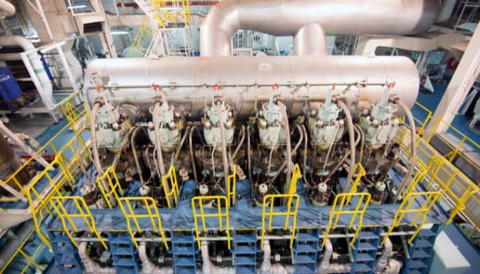
- NT50
- NT100
- NT150
- NT250
- NT350
- 50
- 8000
- Gasket deterioration from thermal stress
- Plate pitting from chloride corrosion on seawater side
- Frame bolt elongation from repeated torquing
Hisaka Works (Japan)
1- RX-10
- RX-20
- RX-30
- UX-01
- UX-10
- UX-20
- UX-40
- 30
- 5000
- Gasket degradation — standard PHE issue
- Plate fouling from seawater
- Frame bolt fatigue
Jiangsu Baode Heat Exchanger
1Jiangsu Nantong Shentong Machinery
1Jiangsu Yuanzhuo Equipment Manufacturing
1Kangrim Heavy Industries (South Korea)
1
- KE-500
- KE-1000
- KE-3000
- KE-5000
- 500
- 20000
- Soot fires — same risk as Aalborg economisers, daily soot blowing mandatory
- Tube erosion from high-velocity exhaust gas
- Feedwater-side corrosion from poor water treatment
- Soot blower mechanism failure
Kelvion (Germany)
1- NX10
- NX25
- NX50
- K055
- K070
- 50
- 5000
- Gasket degradation from age
- Plate fouling
- Frame misalignment from heavy seas vibration
Kelvion Brazed PHE
1
Luoyang Sunrui Ti Precision Casting
1Sasakura Engineering (Japan)
1- VS-15
- VS-25
- VS-50
- VS-75
- VS-100
- Evaporator plate scale buildup from high seawater temperature (>32°C tropics)
- Ejector nozzle erosion from seawater
- Demister pad fouling causing salinity in product water
- Vacuum loss from gasket/seal degradation
Sondex (Danfoss)
1- Fouling or scaling increases differential pressure and reduces heat-transfer performance
- Gasket, seal or tube-joint deterioration causes external leakage
- Plate or tube corrosion, erosion or cracking causes internal cross-contamination between fluid circuits
- Blocked strainers or restricted valves reduce flow and produce abnormal inlet-to-outlet temperatures
- Incorrect reassembly, venting or flow distribution after service causes leakage or poor thermal performance
- High heat transfer efficiency in a small footprint
- Relatively low purchase price and good cost‑performance ratio
- Easy maintenance – gaskets can be replaced on‑site, typically every 5 years
- Modular design allows for quick installation and scaling of capacity
- Suitable for low to medium pressure freshwater, seawater or light oil services
- Gasketed plates limit maximum operating pressure and temperature compared with welded designs
- Susceptible to fouling if used with high‑particulate or oily streams; requires regular cleaning
- Plate corrosion can occur in aggressive seawater environments unless proper material selection is made
- Flow distribution may become uneven as plates age or when fouling occurs
Sondex / Danfoss (Denmark)
1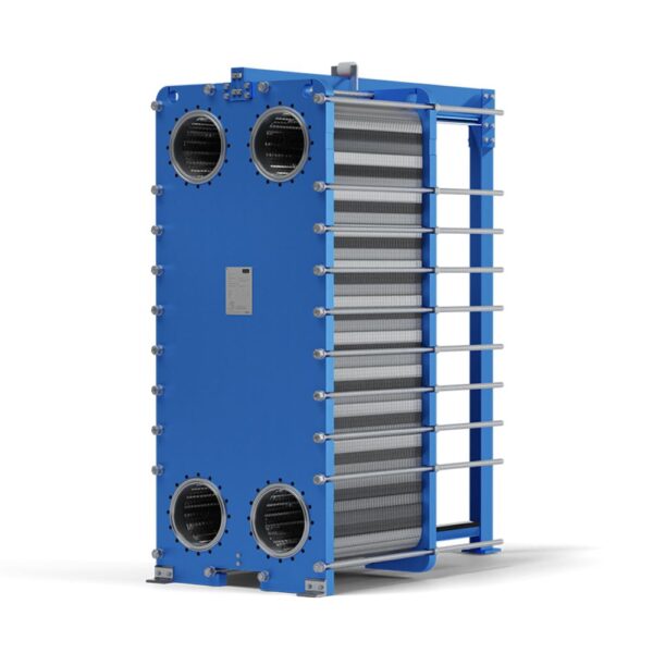
- S4A
- S7A
- S14A
- S19A
- S37
- S62
- 30
- 3000
- Gasket deterioration — standard PHE failure mode
- Plate fouling from seawater side
- Frame alignment issues
SWEP (Sweden)
1- B5
- B8
- B10
- B12
- B15
- B25
- B35
- B80
- B120
- 5
- 300
- Internal fouling — brazed, not cleanable
- Braze joint failure from thermal shock
- Channel blockage from debris
Tranter (USA/Sweden)
1- GX-12
- GX-18
- GX-26
- GX-42
- GX-51
- GX-60
- GC-26
- GC-51
- 30
- 3000
- Gasket deterioration — standard PHE
- Plate fouling from seawater
- Frame alignment issues
Tranter International
1Wärtsilä
1
- MOSS IG 2000
- MOSS IG 5000
- MOSS IG 10000
- Scrubber tower internal corrosion from hot acidic gases
- Demister pad clogging/degradation
- Seawater spray nozzle erosion
- Combustion chamber refractory lining degradation