What to check on a FO Circulating Pump.
A fuel oil circulating pump moves heated, viscosity-corrected fuel oil in a closed loop between the mixing or booster tank and the main engine, running continuously rather than on demand. The engine's injection system only draws off the fuel it actually burns; everything else circulates back to the tank, which is deliberate — the constant flow keeps the fuel at working temperature and sweeps entrained gas and vapour out of the injection pipework before it reaches the injectors. This distinguishes it from a transfer pump, which moves fuel in batches…
What defines this type
A fuel oil circulating pump moves heated, viscosity-corrected fuel oil in a closed loop between the mixing or booster tank and the main engine, running continuously rather than on demand. The engine's injection system only draws off the fuel it actually burns; everything else circulates back to the tank, which is deliberate — the constant flow keeps the fuel at working temperature and sweeps entrained gas and vapour out of the injection pipework before it reaches the injectors. This distinguishes it from a transfer pump, which moves fuel in batches between tanks and stops once the job is done.
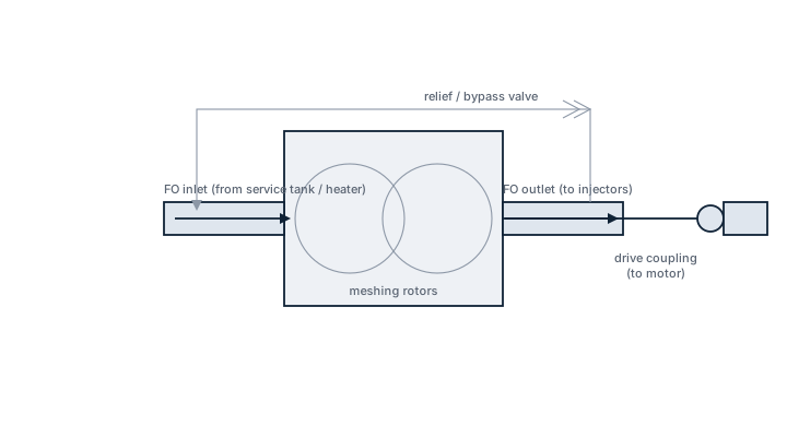
Main components
Pump element
Almost always a screw or gear-type positive displacement pump, chosen because heated heavy fuel oil is viscous and the flow needs to stay steady regardless of small back-pressure changes downstream.
Drive and coupling
A flexible coupling to an electric motor, sized to cope with the torque swings that occur when cold fuel with much higher viscosity than normal is circulated during start-up or after bunkering off-spec fuel.
Relief valve
A spring-loaded bypass fitted across the pump to protect the circuit if a downstream valve is closed against a running pump, since a positive displacement pump will build pressure indefinitely without one.
Strainers
Duplex strainers on the suction side, switchable without stopping flow, to catch debris before it reaches the pump element.
Selection and sizing
Capacity is set by the required circulation rate of the fuel loop, typically several times the engine's maximum consumption, not by the engine's fuel burn alone; the difference is the return flow that carries heat and gas back to the tank. Differential pressure has to cover the loop's total resistance including the heaters, viscosimeter and filters at the fuel's minimum working viscosity, since a thin, hot fuel offers less internal friction inside the pump and can allow slip that a thick fuel would not. Material selection for wetted parts needs to tolerate both heavy fuel oil at 130-150°C and, on dual-fuel-capable systems, distillate fuel at ambient temperature without excessive internal clearance.
Regulations and class
Class rules require duplicated fuel oil circulating pumps for the main engine, so that a single pump failure does not stop propulsion, and the standby pump must be capable of automatic or rapid manual start. Fuel piping and pump installations in way of hot surfaces fall under SOLAS Chapter II-2 requirements for insulation and leakage containment around fuel systems operating above the flash point.
Typical faults
| Fault | Cause | Consequence |
|---|---|---|
| Falling delivery pressure over time | Internal wear of the screw or gear elements from abrasive catalytic fines in the fuel | Increased fuel slip, reduced injection pressure at the engine and possible viscosity control problems |
| Pump runs but no flow develops | Air lock on the suction side after tank changeover or strainer cleaning | Loss of fuel supply to the engine, requiring the pump to be vented before restart |
| Relief valve lifting continuously | Downstream restriction such as a clogged fine filter or closed valve | Fuel recirculating internally through the relief valve, generating heat and wasting pump capacity |
| Excessive noise or vibration | Cavitation from running below the minimum required suction pressure, often after a strainer becomes partly blocked | Accelerated wear of pump internals and coupling |
What to look for in a supplier
- Confirmed compatibility with the fuel viscosity range the ship actually uses, including any low-sulphur distillate fall-back
- Standard flange and coupling dimensions matching the existing motor and pipework, since a mismatch turns a like-for-like replacement into a foundation modification
- Documented wear-part life or clearance data for pumping fuel with typical catalytic fines content
- Availability of spare rotor or gear sets rather than complete pump replacement only
Track delivery pressure at a fixed viscosity and load over successive watches — a slow decline flags internal wear long before the pump fails outright.