"> VHF DSC Radio - Equipment Database

VHF DSC Radio

medium 19 models total

A VHF DSC radio is the GMDSS Sea Area A1 backbone - it distinguishes itself from a plain VHF set by the ability to trigger and receive a digital distress alert automatically, not just carry voice traffic on Channel 16.

Read more — VHF DSC Radio explained

What defines a VHF DSC radio

A VHF Digital Selective Calling (DSC) radio looks like an ordinary VHF set but carries a second, silent channel underneath the voice traffic. Channel 70 carries digital selective calling data - distress alerts, individual and group calls, position reports - while voice communication continues on Channel 16 and the working channels. The distinguishing feature against a non-DSC VHF is the red distress button: pressed and held, it transmits a formatted digital distress alert on Channel 70 containing the vessel's MMSI, and if interfaced with GPS, its position and time, without anyone needing to speak.
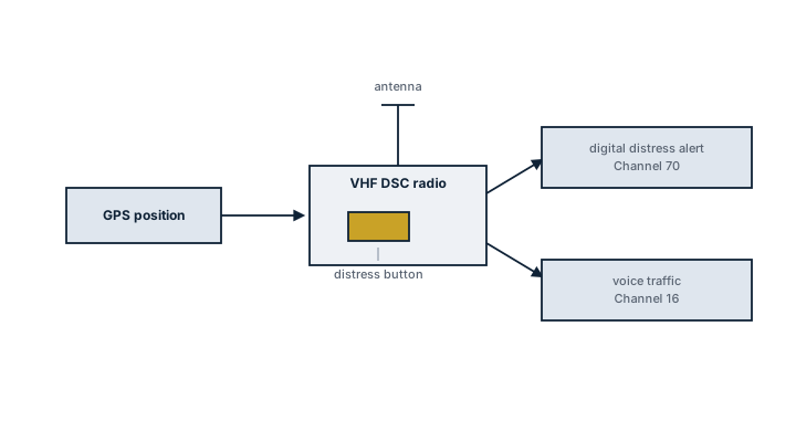
VHF DSC radio signal paths
Block diagram of a VHF DSC radio taking a GPS position and, on pressing the distress button, sending a digital distress alert on Channel 70 as well as carrying ordinary voice traffic on Channel 16.

Within GMDSS, VHF DSC covers Sea Area A1 - waters within range of a shore-based VHF coast station, typically 20 to 40 nautical miles from the coast depending on antenna height. Vessels operating beyond A1 need MF, HF, or satellite equipment in addition, since VHF range does not extend past the horizon.

Main components

Transceiver unit

Combines the voice VHF transceiver with a DSC controller monitoring Channel 70 continuously in the background while the operator uses voice channels.

Distress button

A guarded button, usually requiring a cover to be lifted and held for several seconds, preventing accidental transmission while still being fast to use in a real emergency.

MMSI programming interface

The Maritime Mobile Service Identity is programmed once, typically by an authorised technician, since re-programming after commissioning is restricted to prevent a vessel transmitting under a false identity.

GPS interface

A NMEA input feeding position and time into the DSC controller so a distress alert carries an accurate position; without this interface the set can still send an alert, but without position data.

External antenna and power supply

Fed from an independent circuit, often backed by the ship's emergency battery, so the set stays operational if main power is lost during the casualty that triggers its use.

Selection and sizing

VHF DSC sets are selected by GMDSS equipment class rather than by transmit power alone, since class dictates which vessel categories may carry which set:

  • Output power, typically 1 to 25 watts, with 25 watts the standard for the main distress-capable set.
  • Class D versus Class A/B DSC controller - Class D is standard on most commercial vessels and covers all-ships, individual, and group calling.
  • Integration with the ship's GPS and, on larger vessels, with the bridge alarm system so a received distress relay sounds an audible alarm.
  • Number of installed units - large vessels typically carry a main set on the bridge plus a portable or secondary handheld for lifeboats and bridge wings.

Regulations and class

SOLAS Chapter IV sets the GMDSS carriage requirements, and VHF DSC is mandatory for all SOLAS vessels regardless of sea area, since Sea Area A1 coverage exists almost everywhere a ship transits close to shore. The set must be type-approved to IMO performance standards, and the MMSI must be registered with the flag administration before the set is used. Class societies verify the installation during GMDSS survey, and the annual survey includes a functional test of the distress alert function using the test call facility, since triggering a live distress alert for testing is prohibited.

Typical faults

FaultCauseConsequence
No GPS position in distress alertNMEA interface cable damaged or GPS antenna faultAlert transmits without position, delaying rescue response
Set fails to receive on Channel 70Antenna or coax degradation, often from corrosion at the connectorVessel misses incoming distress relays from other ships
False distress alertsCrew unfamiliar with the guarded button, or a training gap after crew changeUnnecessary SAR response, and repeated false alerts can draw regulatory scrutiny
MMSI mismatch or unregisteredSet replaced or reprogrammed without updating flag state registrationRescue coordination cannot identify the vessel from the alert

What to look for in a supplier

  • IMO/GMDSS type approval certificate matching the flag state's accepted equipment list.
  • Correct MMSI programming procedure and documentation at commissioning.
  • Confirmed GPS/NMEA interface compatibility with the ship's existing navigation equipment.
  • Backup power arrangement tested as part of commissioning, not assumed from the wiring diagram.
  • Training support for the crew on distress button use and false-alert cancellation procedure.

Run the test call function every watch handover, not just at the scheduled radio log entry - a dead Channel 70 receiver is invisible during normal voice traffic and only shows up when someone actually needs it.

Marine VHF radio
Marine VHF radio. Photo: No machine-readable author provided. Ulflarsen assumed (based on copyr, CC BY-SA 3.0, via Wikimedia Commons

8 manufacturers · 19 models

Icom Marine

5
IC-M510 VHF/DSC Marine unverified
Power (W)
25
Dsc
ja
IMO Compliant
ja
Ais receiver
ja
Common Failures & Inspection Points
  • Transmitter or receiver failure caused by RF, antenna, feeder or power faults, noticed as poor range, failed checks or loss of reception
  • Antenna/feed-line deterioration caused by corrosion, water ingress or mechanical damage, noticed as intermittent operation or reduced range
  • Control or audio failure caused by handset, microphone, display, keypad or controller faults, noticed as inability to operate normal functions
  • Position/identity or data-interface failure caused by wiring or configuration faults, noticed as missing or incorrect safety data
  • Power-source failure caused by breaker, fuse, converter or emergency-supply faults, noticed as dead equipment or loss of required GMDSS availability
Service: Carry out the permitted operational/self-tests, inspect antennas, feeders, connectors, controls and cooling, and verify normal and emergency power where required. Check vessel identity, position and interfaces appropriate to the equipment type and review recurring alarms or logbook entries. A radio surveyor should confirm the installation and programmed data against the approved radio documentation.
Spare Parts: Carry fuses, approved handsets/microphones or control accessories where applicable, antenna connectors and feeder repair items, selected power-supply components and manufacturer-recommended interface/control spares. The spare scale should match the vessel's declared GMDSS maintenance method.
Use Cases: Used on merchant, offshore, passenger and workboat fleets for distress, safety and routine maritime communications according to the equipment's approved GMDSS function.
IC-M423G VHF/DSC unverified
Power (W)
25
Dsc
ja
Gps equipped
ja
Common Failures & Inspection Points
  • Antenna or feeder corrosion causes poor range, weak received signals or high transmitter reflected power
  • Microphone, handset or speaker faults cause missing or distorted audio while the radio otherwise powers normally
  • Power-supply, battery or charging faults cause resets, low-voltage alarms or inability to transmit at required power
  • DSC or GPS-interface faults on equipped units cause distress-function alarms or missing position information
  • Internal transceiver or control faults cause intermittent transmission, receiver deafness or unavailable channels
Service: Check antenna and feeder condition, channel operation, audio quality, power supply and emergency or portable battery arrangements where applicable. Test DSC functions only with the approved test method on DSC-equipped radios. Verify programmed identity and position input. RF output and sensitivity measurements should follow manufacturer and GMDSS service procedures.
Spare Parts: Carry fuses, microphones or handsets, battery packs or chargers for portable sets, antenna connectors, power leads and selected approved control accessories.
Use Cases: Bridge communications, port operations, pilotage, distress and safety communications on commercial, offshore and small craft.
IC-M330GE VHF/DSC unverified
Power (W)
25
Dsc
ja
IMO Compliant
ja
Common Failures & Inspection Points
  • Antenna or feeder corrosion causes poor range, weak received signals or high transmitter reflected power
  • Microphone, handset or speaker faults cause missing or distorted audio while the radio otherwise powers normally
  • Power-supply, battery or charging faults cause resets, low-voltage alarms or inability to transmit at required power
  • DSC or GPS-interface faults on equipped units cause distress-function alarms or missing position information
  • Internal transceiver or control faults cause intermittent transmission, receiver deafness or unavailable channels
Service: Check antenna and feeder condition, channel operation, audio quality, power supply and emergency or portable battery arrangements where applicable. Test DSC functions only with the approved test method on DSC-equipped radios. Verify programmed identity and position input. RF output and sensitivity measurements should follow manufacturer and GMDSS service procedures.
Spare Parts: Carry fuses, microphones or handsets, battery packs or chargers for portable sets, antenna connectors, power leads and selected approved control accessories.
Use Cases: Bridge communications, port operations, pilotage, distress and safety communications on commercial, offshore and small craft.
IC-M93D VHF/DSC Handheld unverified
Power (W)
5
Dsc
ja
Gps equipped
ja
Handheld
ja
Common Failures & Inspection Points
  • Loss of supply power from a tripped breaker, failed power unit, loose connection, or depleted reserve battery causes a dead unit, rebooting, or failure to transmit
  • Antenna, feeder, connector, or matching fault caused by corrosion, water ingress, or physical damage results in poor range, failed transmission, or weak received signals
  • Control-panel, display, keypad, or software faults can prevent channel selection, message handling, or normal operator input
  • Interface or position-data failure caused by wiring, configuration, or sensor faults can remove position information or connected-system data
  • Internal transmitter, receiver, or modem faults caused by component ageing or overheating can produce intermittent communication, alarms, or inability to establish a link
Service: Verify primary and reserve power, antenna and feeder condition, distress and safety functions permitted for routine testing, interfaces, audio quality, time and position inputs, and logged self-test results. Any regulatory test or adjustment must follow the vessel's radio procedures and manufacturer documentation.
Spare Parts: Carry the model-specific fuses, approved power-supply items, handset or microphone accessories, connector and sealing items, and critical interface or antenna components recommended by the manufacturer and vessel radio-maintenance plan.
Use Cases: Used on SOLAS merchant ships, offshore vessels, passenger ships, fishing vessels, workboats, and other craft requiring marine radio, distress, safety, or navigation communications.
IC-M506 VHF/DSC GMDSS unverified
Power (W)
25
Dsc
ja
IMO Compliant
ja
Ais receiver
ja
Common Failures & Inspection Points
  • Transmitter or receiver failure caused by RF, antenna, feeder or power faults, noticed as poor range, failed checks or loss of reception
  • Antenna/feed-line deterioration caused by corrosion, water ingress or mechanical damage, noticed as intermittent operation or reduced range
  • Control or audio failure caused by handset, microphone, display, keypad or controller faults, noticed as inability to operate normal functions
  • Position/identity or data-interface failure caused by wiring or configuration faults, noticed as missing or incorrect safety data
  • Power-source failure caused by breaker, fuse, converter or emergency-supply faults, noticed as dead equipment or loss of required GMDSS availability
Service: Carry out the permitted operational/self-tests, inspect antennas, feeders, connectors, controls and cooling, and verify normal and emergency power where required. Check vessel identity, position and interfaces appropriate to the equipment type and review recurring alarms or logbook entries. A radio surveyor should confirm the installation and programmed data against the approved radio documentation.
Spare Parts: Carry fuses, approved handsets/microphones or control accessories where applicable, antenna connectors and feeder repair items, selected power-supply components and manufacturer-recommended interface/control spares. The spare scale should match the vessel's declared GMDSS maintenance method.
Use Cases: Used on merchant, offshore, passenger and workboat fleets for distress, safety and routine maritime communications according to the equipment's approved GMDSS function.

Sailor

3
Sailor 6222 VHF DSC unverified
Power (W)
25
Channels
57
Dsc
ja
IMO Compliant
ja
Common Failures & Inspection Points
  • Transmitter or receiver failure caused by RF, antenna, feeder or power faults, noticed as poor range, failed checks or loss of reception
  • Antenna/feed-line deterioration caused by corrosion, water ingress or mechanical damage, noticed as intermittent operation or reduced range
  • Control or audio failure caused by handset, microphone, display, keypad or controller faults, noticed as inability to operate normal functions
  • Position/identity or data-interface failure caused by wiring or configuration faults, noticed as missing or incorrect safety data
  • Power-source failure caused by breaker, fuse, converter or emergency-supply faults, noticed as dead equipment or loss of required GMDSS availability
Service: Carry out the permitted operational/self-tests, inspect antennas, feeders, connectors, controls and cooling, and verify normal and emergency power where required. Check vessel identity, position and interfaces appropriate to the equipment type and review recurring alarms or logbook entries. A radio surveyor should confirm the installation and programmed data against the approved radio documentation.
Spare Parts: Carry fuses, approved handsets/microphones or control accessories where applicable, antenna connectors and feeder repair items, selected power-supply components and manufacturer-recommended interface/control spares. The spare scale should match the vessel's declared GMDSS maintenance method.
Use Cases: Used on merchant, offshore, passenger and workboat fleets for distress, safety and routine maritime communications according to the equipment's approved GMDSS function.
Sailor 6248 VHF DSC unverified
Power (W)
25
Channels
57
Dsc
ja
IMO Compliant
ja
Dual watch
ja
Common Failures & Inspection Points
  • Transmitter or receiver failure caused by RF, antenna, feeder or power faults, noticed as poor range, failed checks or loss of reception
  • Antenna/feed-line deterioration caused by corrosion, water ingress or mechanical damage, noticed as intermittent operation or reduced range
  • Control or audio failure caused by handset, microphone, display, keypad or controller faults, noticed as inability to operate normal functions
  • Position/identity or data-interface failure caused by wiring or configuration faults, noticed as missing or incorrect safety data
  • Power-source failure caused by breaker, fuse, converter or emergency-supply faults, noticed as dead equipment or loss of required GMDSS availability
Service: Carry out the permitted operational/self-tests, inspect antennas, feeders, connectors, controls and cooling, and verify normal and emergency power where required. Check vessel identity, position and interfaces appropriate to the equipment type and review recurring alarms or logbook entries. A radio surveyor should confirm the installation and programmed data against the approved radio documentation.
Spare Parts: Carry fuses, approved handsets/microphones or control accessories where applicable, antenna connectors and feeder repair items, selected power-supply components and manufacturer-recommended interface/control spares. The spare scale should match the vessel's declared GMDSS maintenance method.
Use Cases: Used on merchant, offshore, passenger and workboat fleets for distress, safety and routine maritime communications according to the equipment's approved GMDSS function.
Sailor 6215 VHF DSC unverified
Power (W)
25
Dsc
ja
IMO Compliant
ja
Common Failures & Inspection Points
  • Transmitter or receiver failure caused by RF, antenna, feeder or power faults, noticed as poor range, failed checks or loss of reception
  • Antenna/feed-line deterioration caused by corrosion, water ingress or mechanical damage, noticed as intermittent operation or reduced range
  • Control or audio failure caused by handset, microphone, display, keypad or controller faults, noticed as inability to operate normal functions
  • Position/identity or data-interface failure caused by wiring or configuration faults, noticed as missing or incorrect safety data
  • Power-source failure caused by breaker, fuse, converter or emergency-supply faults, noticed as dead equipment or loss of required GMDSS availability
Service: Carry out the permitted operational/self-tests, inspect antennas, feeders, connectors, controls and cooling, and verify normal and emergency power where required. Check vessel identity, position and interfaces appropriate to the equipment type and review recurring alarms or logbook entries. A radio surveyor should confirm the installation and programmed data against the approved radio documentation.
Spare Parts: Carry fuses, approved handsets/microphones or control accessories where applicable, antenna connectors and feeder repair items, selected power-supply components and manufacturer-recommended interface/control spares. The spare scale should match the vessel's declared GMDSS maintenance method.
Use Cases: Used on merchant, offshore, passenger and workboat fleets for distress, safety and routine maritime communications according to the equipment's approved GMDSS function.

Furuno

2
FM-8900S VHF GMDSS unverified
Power (W)
25
Channels
57
Dsc
ja
IMO Compliant
ja
Common Failures & Inspection Points
  • Transmitter or receiver failure caused by RF, antenna, feeder or power faults, noticed as poor range, failed checks or loss of reception
  • Antenna/feed-line deterioration caused by corrosion, water ingress or mechanical damage, noticed as intermittent operation or reduced range
  • Control or audio failure caused by handset, microphone, display, keypad or controller faults, noticed as inability to operate normal functions
  • Position/identity or data-interface failure caused by wiring or configuration faults, noticed as missing or incorrect safety data
  • Power-source failure caused by breaker, fuse, converter or emergency-supply faults, noticed as dead equipment or loss of required GMDSS availability
Service: Carry out the permitted operational/self-tests, inspect antennas, feeders, connectors, controls and cooling, and verify normal and emergency power where required. Check vessel identity, position and interfaces appropriate to the equipment type and review recurring alarms or logbook entries. A radio surveyor should confirm the installation and programmed data against the approved radio documentation.
Spare Parts: Carry fuses, approved handsets/microphones or control accessories where applicable, antenna connectors and feeder repair items, selected power-supply components and manufacturer-recommended interface/control spares. The spare scale should match the vessel's declared GMDSS maintenance method.
Use Cases: Used on merchant, offshore, passenger and workboat fleets for distress, safety and routine maritime communications according to the equipment's approved GMDSS function.
FM-4800 VHF/DSC GMDSS unverified
Power (W)
25
Dsc
ja
IMO Compliant
ja
Common Failures & Inspection Points
  • Loss of supply power from a tripped breaker, failed power unit, loose connection, or depleted reserve battery causes a dead unit, rebooting, or failure to transmit
  • Antenna, feeder, connector, or matching fault caused by corrosion, water ingress, or physical damage results in poor range, failed transmission, or weak received signals
  • Control-panel, display, keypad, or software faults can prevent channel selection, message handling, or normal operator input
  • Interface or position-data failure caused by wiring, configuration, or sensor faults can remove position information or connected-system data
  • Internal transmitter, receiver, or modem faults caused by component ageing or overheating can produce intermittent communication, alarms, or inability to establish a link
Service: Verify primary and reserve power, antenna and feeder condition, distress and safety functions permitted for routine testing, interfaces, audio quality, time and position inputs, and logged self-test results. Any regulatory test or adjustment must follow the vessel's radio procedures and manufacturer documentation.
Spare Parts: Carry the model-specific fuses, approved power-supply items, handset or microphone accessories, connector and sealing items, and critical interface or antenna components recommended by the manufacturer and vessel radio-maintenance plan.
Use Cases: Used on SOLAS merchant ships, offshore vessels, passenger ships, fishing vessels, workboats, and other craft requiring marine radio, distress, safety, or navigation communications.

JRC

2
JHS-770S VHF DSC unverified
Power (W)
25
Dsc
ja
IMO Compliant
ja
Common Failures & Inspection Points
  • Antenna or feeder corrosion causes poor range, weak received signals or high transmitter reflected power
  • Microphone, handset or speaker faults cause missing or distorted audio while the radio otherwise powers normally
  • Power-supply, battery or charging faults cause resets, low-voltage alarms or inability to transmit at required power
  • DSC or GPS-interface faults on equipped units cause distress-function alarms or missing position information
  • Internal transceiver or control faults cause intermittent transmission, receiver deafness or unavailable channels
Service: Check antenna and feeder condition, channel operation, audio quality, power supply and emergency or portable battery arrangements where applicable. Test DSC functions only with the approved test method on DSC-equipped radios. Verify programmed identity and position input. RF output and sensitivity measurements should follow manufacturer and GMDSS service procedures.
Spare Parts: Carry fuses, microphones or handsets, battery packs or chargers for portable sets, antenna connectors, power leads and selected approved control accessories.
Use Cases: Bridge communications, port operations, pilotage, distress and safety communications on commercial, offshore and small craft.
JHS-780D VHF DSC GMDSS unverified
Power (W)
25
Dsc
ja
IMO Compliant
ja
Common Failures & Inspection Points
  • Transmitter or receiver failure caused by RF, antenna, feeder or power faults, noticed as poor range, failed checks or loss of reception
  • Antenna/feed-line deterioration caused by corrosion, water ingress or mechanical damage, noticed as intermittent operation or reduced range
  • Control or audio failure caused by handset, microphone, display, keypad or controller faults, noticed as inability to operate normal functions
  • Position/identity or data-interface failure caused by wiring or configuration faults, noticed as missing or incorrect safety data
  • Power-source failure caused by breaker, fuse, converter or emergency-supply faults, noticed as dead equipment or loss of required GMDSS availability
Service: Carry out the permitted operational/self-tests, inspect antennas, feeders, connectors, controls and cooling, and verify normal and emergency power where required. Check vessel identity, position and interfaces appropriate to the equipment type and review recurring alarms or logbook entries. A radio surveyor should confirm the installation and programmed data against the approved radio documentation.
Spare Parts: Carry fuses, approved handsets/microphones or control accessories where applicable, antenna connectors and feeder repair items, selected power-supply components and manufacturer-recommended interface/control spares. The spare scale should match the vessel's declared GMDSS maintenance method.
Use Cases: Used on merchant, offshore, passenger and workboat fleets for distress, safety and routine maritime communications according to the equipment's approved GMDSS function.

Simrad

2
RS40 VHF/DSC Marine unverified
Power (W)
25
Dsc
ja
IMO Compliant
ja
Common Failures & Inspection Points
  • Transmitter or receiver failure caused by RF, antenna, feeder or power faults, noticed as poor range, failed checks or loss of reception
  • Antenna/feed-line deterioration caused by corrosion, water ingress or mechanical damage, noticed as intermittent operation or reduced range
  • Control or audio failure caused by handset, microphone, display, keypad or controller faults, noticed as inability to operate normal functions
  • Position/identity or data-interface failure caused by wiring or configuration faults, noticed as missing or incorrect safety data
  • Power-source failure caused by breaker, fuse, converter or emergency-supply faults, noticed as dead equipment or loss of required GMDSS availability
Service: Carry out the permitted operational/self-tests, inspect antennas, feeders, connectors, controls and cooling, and verify normal and emergency power where required. Check vessel identity, position and interfaces appropriate to the equipment type and review recurring alarms or logbook entries. A radio surveyor should confirm the installation and programmed data against the approved radio documentation.
Spare Parts: Carry fuses, approved handsets/microphones or control accessories where applicable, antenna connectors and feeder repair items, selected power-supply components and manufacturer-recommended interface/control spares. The spare scale should match the vessel's declared GMDSS maintenance method.
Use Cases: Used on merchant, offshore, passenger and workboat fleets for distress, safety and routine maritime communications according to the equipment's approved GMDSS function.
RS100 VHF/DSC/AIS unverified
Power (W)
25
Dsc
ja
Ais receiver
ja
IMO Compliant
ja
Common Failures & Inspection Points
  • Transmitter or receiver failure caused by RF, antenna, feeder or power faults, noticed as poor range, failed checks or loss of reception
  • Antenna/feed-line deterioration caused by corrosion, water ingress or mechanical damage, noticed as intermittent operation or reduced range
  • Control or audio failure caused by handset, microphone, display, keypad or controller faults, noticed as inability to operate normal functions
  • Position/identity or data-interface failure caused by wiring or configuration faults, noticed as missing or incorrect safety data
  • Power-source failure caused by breaker, fuse, converter or emergency-supply faults, noticed as dead equipment or loss of required GMDSS availability
Service: Carry out the permitted operational/self-tests, inspect antennas, feeders, connectors, controls and cooling, and verify normal and emergency power where required. Check vessel identity, position and interfaces appropriate to the equipment type and review recurring alarms or logbook entries. A radio surveyor should confirm the installation and programmed data against the approved radio documentation.
Spare Parts: Carry fuses, approved handsets/microphones or control accessories where applicable, antenna connectors and feeder repair items, selected power-supply components and manufacturer-recommended interface/control spares. The spare scale should match the vessel's declared GMDSS maintenance method.
Use Cases: Used on merchant, offshore, passenger and workboat fleets for distress, safety and routine maritime communications according to the equipment's approved GMDSS function.

Standard Horizon

2
GX6000 VHF/DSC unverified
Power (W)
25
Dsc
ja
Ais receiver
ja
Common Failures & Inspection Points
  • Antenna, feeder or tuning fault caused by corrosion, damaged cabling or poor connections, resulting in weak transmission, reception problems or equipment alarms
  • Power-supply or backup-battery failure caused by charger defects, aged batteries or wiring faults, resulting in loss of availability when main power is removed
  • Transmitter or receiver failure caused by RF-component or electronic faults, resulting in inability to establish communications or receive expected traffic
  • Position or time-input failure caused by GNSS or network faults, resulting in missing or incorrect data in distress or DSC functions
  • Control, display or software fault caused by hardware failure or configuration problems, resulting in frozen controls, error messages or unavailable functions
Service: Perform operational and self-tests permitted by the vessel's procedures without generating unintended distress alerts. Inspect antennas, feeders, grounding, power supplies, backup batteries and connected navigation-data inputs. Verify station identity, position input, time and configured communication services against approved records. Check printers, handsets, microphones and alarm interfaces where fitted. Maintain software, licenses and service subscriptions required by the installed system. Refer to manufacturer and regulatory documentation for exact test methods, battery criteria and approved servicing.
Spare Parts: Keep fuses, handset or microphone accessories, printer consumables where applicable, selected power-supply components and manufacturer-recommended electronic spares. Antenna or feeder repair materials and backup-battery arrangements should reflect the vessel's redundancy plan. Preserve type approval and programmed identity when replacing core units.
Use Cases: Distress, urgency, safety and routine maritime communications within the vessel's GMDSS and operational communications fit.
GX2200 Matrix VHF/AIS unverified
Power (W)
25
Dsc
ja
Ais receiver
ja
Common Failures & Inspection Points
  • Loss of supply power from a tripped breaker, failed power unit, loose connection, or depleted reserve battery causes a dead unit, rebooting, or failure to transmit
  • Antenna, feeder, connector, or matching fault caused by corrosion, water ingress, or physical damage results in poor range, failed transmission, or weak received signals
  • Control-panel, display, keypad, or software faults can prevent channel selection, message handling, or normal operator input
  • Interface or position-data failure caused by wiring, configuration, or sensor faults can remove position information or connected-system data
  • Internal transmitter, receiver, or modem faults caused by component ageing or overheating can produce intermittent communication, alarms, or inability to establish a link
Service: Verify primary and reserve power, antenna and feeder condition, distress and safety functions permitted for routine testing, interfaces, audio quality, time and position inputs, and logged self-test results. Any regulatory test or adjustment must follow the vessel's radio procedures and manufacturer documentation.
Spare Parts: Carry the model-specific fuses, approved power-supply items, handset or microphone accessories, connector and sealing items, and critical interface or antenna components recommended by the manufacturer and vessel radio-maintenance plan.
Use Cases: Used on SOLAS merchant ships, offshore vessels, passenger ships, fishing vessels, workboats, and other craft requiring marine radio, distress, safety, or navigation communications.

Vesper Marine

2
Cortex H1 VHF/AIS unverified
Power (W)
25
Dsc
ja
Ais transponder
ja
Touchscreen
ja
Common Failures & Inspection Points
  • Antenna, feeder or tuning fault caused by corrosion, damaged cabling or poor connections, resulting in weak transmission, reception problems or equipment alarms
  • Power-supply or backup-battery failure caused by charger defects, aged batteries or wiring faults, resulting in loss of availability when main power is removed
  • Transmitter or receiver failure caused by RF-component or electronic faults, resulting in inability to establish communications or receive expected traffic
  • Position or time-input failure caused by GNSS or network faults, resulting in missing or incorrect data in distress or DSC functions
  • Control, display or software fault caused by hardware failure or configuration problems, resulting in frozen controls, error messages or unavailable functions
Service: Perform operational and self-tests permitted by the vessel's procedures without generating unintended distress alerts. Inspect antennas, feeders, grounding, power supplies, backup batteries and connected navigation-data inputs. Verify station identity, position input, time and configured communication services against approved records. Check printers, handsets, microphones and alarm interfaces where fitted. Maintain software, licenses and service subscriptions required by the installed system. Refer to manufacturer and regulatory documentation for exact test methods, battery criteria and approved servicing.
Spare Parts: Keep fuses, handset or microphone accessories, printer consumables where applicable, selected power-supply components and manufacturer-recommended electronic spares. Antenna or feeder repair materials and backup-battery arrangements should reflect the vessel's redundancy plan. Preserve type approval and programmed identity when replacing core units.
Use Cases: Distress, urgency, safety and routine maritime communications within the vessel's GMDSS and operational communications fit.
Cortex H1P VHF/AIS Premium unverified
Power (W)
25
Dsc
ja
Ais transponder
ja
Touchscreen
ja
Remote monitoring
ja
Common Failures & Inspection Points
  • Loss of supply power from a tripped breaker, failed power unit, loose connection, or depleted reserve battery causes a dead unit, rebooting, or failure to transmit
  • Antenna, feeder, connector, or matching fault caused by corrosion, water ingress, or physical damage results in poor range, failed transmission, or weak received signals
  • Control-panel, display, keypad, or software faults can prevent channel selection, message handling, or normal operator input
  • Interface or position-data failure caused by wiring, configuration, or sensor faults can remove position information or connected-system data
  • Internal transmitter, receiver, or modem faults caused by component ageing or overheating can produce intermittent communication, alarms, or inability to establish a link
Service: Verify primary and reserve power, antenna and feeder condition, distress and safety functions permitted for routine testing, interfaces, audio quality, time and position inputs, and logged self-test results. Any regulatory test or adjustment must follow the vessel's radio procedures and manufacturer documentation.
Spare Parts: Carry the model-specific fuses, approved power-supply items, handset or microphone accessories, connector and sealing items, and critical interface or antenna components recommended by the manufacturer and vessel radio-maintenance plan.
Use Cases: Used on SOLAS merchant ships, offshore vessels, passenger ships, fishing vessels, workboats, and other craft requiring marine radio, distress, safety, or navigation communications.

Navico

1
B&G V60-B VHF/AIS/DSC unverified
Power (W)
25
Dsc
ja
Ais transponder
ja
Common Failures & Inspection Points
  • Loss of supply power from a tripped breaker, failed power unit, loose connection, or depleted reserve battery causes a dead unit, rebooting, or failure to transmit
  • Antenna, feeder, connector, or matching fault caused by corrosion, water ingress, or physical damage results in poor range, failed transmission, or weak received signals
  • Control-panel, display, keypad, or software faults can prevent channel selection, message handling, or normal operator input
  • Interface or position-data failure caused by wiring, configuration, or sensor faults can remove position information or connected-system data
  • Internal transmitter, receiver, or modem faults caused by component ageing or overheating can produce intermittent communication, alarms, or inability to establish a link
Service: Verify primary and reserve power, antenna and feeder condition, distress and safety functions permitted for routine testing, interfaces, audio quality, time and position inputs, and logged self-test results. Any regulatory test or adjustment must follow the vessel's radio procedures and manufacturer documentation.
Spare Parts: Carry the model-specific fuses, approved power-supply items, handset or microphone accessories, connector and sealing items, and critical interface or antenna components recommended by the manufacturer and vessel radio-maintenance plan.
Use Cases: Used on SOLAS merchant ships, offshore vessels, passenger ships, fishing vessels, workboats, and other craft requiring marine radio, distress, safety, or navigation communications.