What to check on a MF/HF SSB Radio (GMDSS).
MF/HF single sideband (SSB) radio provides GMDSS distress alerting, safety communication and voice traffic over ranges from roughly 150 nautical miles on medium frequency up to several thousand nautical miles on high frequency, using ionospheric skywave propagation rather than a satellite link. This is what separates it from Inmarsat-based GMDSS equipment: SSB works with no satellite visibility at all, which matters in polar regions above roughly 76 degrees latitude that fall outside the coverage of the geostationary satellites most GMDSS ships rely on, and it keeps working during the kind…
What Makes This Type
MF/HF single sideband (SSB) radio provides GMDSS distress alerting, safety communication and voice traffic over ranges from roughly 150 nautical miles on medium frequency up to several thousand nautical miles on high frequency, using ionospheric skywave propagation rather than a satellite link. This is what separates it from Inmarsat-based GMDSS equipment: SSB works with no satellite visibility at all, which matters in polar regions above roughly 76 degrees latitude that fall outside the coverage of the geostationary satellites most GMDSS ships rely on, and it keeps working during the kind of widespread outage that can affect a single satellite operator. Digital selective calling (DSC) on the dedicated distress frequencies automates the alert itself, sending vessel identity and position so a voice watch is not the only way a distress call gets through.
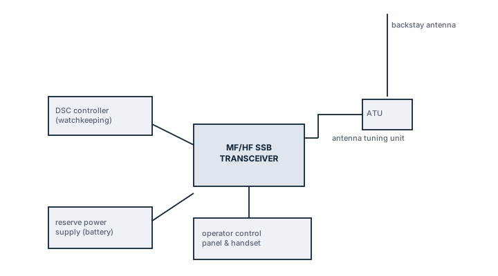
Main Components
- MF/HF transceiver: the transmitter/receiver unit covering the required frequency bands, typically 1.6 to 27.5 MHz, with the specific GMDSS distress and safety channels pre-programmed and protected from accidental retuning.
- DSC controller: a dedicated unit or integrated function that formats and sends the digital distress alert on 2187.5 kHz (MF) and 8414.5 kHz (HF), and monitors those frequencies continuously for incoming alerts.
- Automatic antenna tuner: matches the transmitter output to the whip or backstay antenna across the wide frequency range the equipment covers, since a single fixed-length antenna cannot be resonant at every band without one.
- Radio installation battery and charger: a dedicated reserve source of energy separate from the ship's main supply, sized to power the distress and safety functions for a set minimum period after a mains failure.
Selection and Sizing
The sea area the vessel is certified to operate in under GMDSS (A1 through A4) drives what has to be fitted; MF/HF SSB with DSC becomes mandatory once a vessel's voyages take it into Sea Area A3 or A4, beyond VHF coverage and, for A4, beyond Inmarsat coverage as well. Transmitter power, typically around 150 watts PEP on smaller installations, is matched to the antenna and expected range requirement rather than chosen independently. Battery capacity is sized against SOLAS's minimum reserve power duration for the radio installation, not just against what fits in the available battery locker.
Regulations and Class
SOLAS Chapter IV sets the GMDSS carriage requirements by sea area, and MF/HF SSB with DSC is mandatory equipment for vessels operating in Sea Area A3 or A4 unless an accepted alternative combination is fitted. Radio equipment requires type approval and the installation is checked at survey for correct programming of the distress frequencies, functioning of the automatic antenna tuner and the reserve battery's ability to meet its rated duration. A radio log and record of DSC test calls is part of what surveyors and port state control check.
Typical Faults
| Fault | Consequence |
|---|---|
| Antenna tuner failure or corroded antenna connection | Transmitter cannot load properly into the antenna, cutting effective range well below rated performance |
| Reserve battery capacity degraded with age | Radio installation cannot meet its minimum operating duration after a mains failure, a survey finding |
| DSC controller left un-monitored or muted | Incoming distress alerts on the watch frequencies go unnoticed |
| Incorrect MMSI programming after a flag or name change | Distress alerts transmit with the wrong vessel identity, delaying rescue coordination |
What to Look for in a Supplier
- Type approval covering the vessel's certified GMDSS sea area, not just general radio equipment approval.
- Documented battery reserve capacity testing procedure and replacement schedule.
- Technician familiarity with antenna tuner fault-finding specifically, since this is the component that fails most often in service.
Confirm the MMSI programmed into the DSC controller matches the current certificate after any flag, name or ownership change - it is a five-minute check that prevents a distress alert going out under the wrong identity.