What to check on a GMDSS Console.
GMDSS is not one device but a set of separate radio and satellite systems - MF/HF DSC, VHF DSC, NAVTEX, Inmarsat-C, SART - each required for different sea areas. The console is the physical and operational integration point: rather than scattered separate units, it groups the controls, displays and alarm panel the watchkeeper actually needs to send or receive a distress alert without hunting across the bridge for the right piece of equipment during an emergency. What distinguishes one console fit from another is mainly the sea area (A1 to…
What sets this type apart
GMDSS is not one device but a set of separate radio and satellite systems - MF/HF DSC, VHF DSC, NAVTEX, Inmarsat-C, SART - each required for different sea areas. The console is the physical and operational integration point: rather than scattered separate units, it groups the controls, displays and alarm panel the watchkeeper actually needs to send or receive a distress alert without hunting across the bridge for the right piece of equipment during an emergency. What distinguishes one console fit from another is mainly the sea area (A1 to A4) the ship is certified for, since each area requires a different combination of the underlying systems.
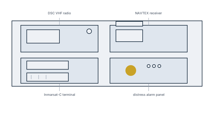
Main components
- VHF DSC radio - short-range distress and routine calling, mandatory on essentially all GMDSS-fitted ships, covering sea area A1 near shore-based VHF coverage.
- MF/HF DSC transceiver - longer range distress alerting and voice/telex communication for sea areas A2 and A3, using digital selective calling to raise an automated alarm at shore stations.
- Inmarsat-C terminal (or equivalent satellite system) - store-and-forward distress messaging and maritime safety information via satellite, covering ocean areas without MF/HF or VHF shore coverage.
- NAVTEX receiver - automatically prints or displays navigational and meteorological safety warnings for the coastal area the ship is transiting.
- Distress alarm panel and reserve power source - a dedicated panel that lets the watchkeeper trigger a distress alert instantly, backed by a battery source independent of the ship's main and emergency supply so it functions even after a total power failure.
Selection and sizing
The console's equipment fit is determined by the sea areas the ship is certified to operate in, not by owner preference: an A1-only coastal vessel needs far less than a ship certified for A4 (polar/high-latitude) operation, which requires the full suite including satellite communication able to function outside Inmarsat's geostationary coverage. Console layout and redundancy - whether a second independent means of distress alerting is provided - also follow ship type and passenger carriage requirements rather than a single universal specification.
Regulations and class
GMDSS carriage requirements are set out in SOLAS chapter IV, tied directly to the sea area(s) a ship is certified for. Equipment must be maintained under one of the approved maintenance regimes - shore-based maintenance, at-sea duplication, or a combination - with a Radio Log kept and equipment tested regularly, including reserve power source checks. A Radio Survey confirms the fit is complete and functioning for the ship's certified sea areas, and any change to those sea areas requires the equipment fit to be reassessed.
Typical faults
- Reserve (backup) battery source not tested or discharged without the crew noticing - defeats the purpose of independent power exactly when main power is lost.
- DSC radio with an outdated or incorrectly programmed MMSI - distress alert transmitted with wrong ship identity, delaying rescue coordination.
- NAVTEX left set to the wrong station selection for the current transit area - safety messages for the actual coastal area are missed.
- False alarms from accidental distress button activation, leading crew to disable or ignore alarms rather than fix the guard cover or training issue - a serious risk if a real alert is then also ignored.
What to look for in a supplier
- Type approval covering the specific sea areas (A1-A4) the ship needs, confirmed against the vessel's actual trading pattern.
- Maintenance regime support matching what the operator has chosen - shore-based service network reach, or duplication and spares for at-sea maintenance.
- Console ergonomics allowing the watchkeeper to reach the distress alarm and DSC controls without searching, given that these are used under stress.
- Confirmed reserve power source sizing and independent testing capability built into the installation.
Test the reserve power source under an actual simulated main-power-off condition periodically, not just by checking a status light - a battery that reads as present can still be too weak to carry a real distress transmission.