What to check on a Vapor Recovery/Return System.
Ordinary tank venting through pressure/vacuum valves lets displaced vapor escape to atmosphere as cargo is loaded. A vapor recovery or vapor return system instead connects the ship's vapor manifold to shore piping so that vapor displaced by the incoming liquid cargo is pushed back to the terminal's recovery or flare system rather than vented on deck. It is specific to the loading evolution at terminals fitted for vapor balancing or vapor recovery; it does not replace the ship's normal P/V valves and mast risers, which remain the safety venting path…
What Sets This Type Apart
Ordinary tank venting through pressure/vacuum valves lets displaced vapor escape to atmosphere as cargo is loaded. A vapor recovery or vapor return system instead connects the ship's vapor manifold to shore piping so that vapor displaced by the incoming liquid cargo is pushed back to the terminal's recovery or flare system rather than vented on deck. It is specific to the loading evolution at terminals fitted for vapor balancing or vapor recovery; it does not replace the ship's normal P/V valves and mast risers, which remain the safety venting path when the vapor connection is not in use or fails.
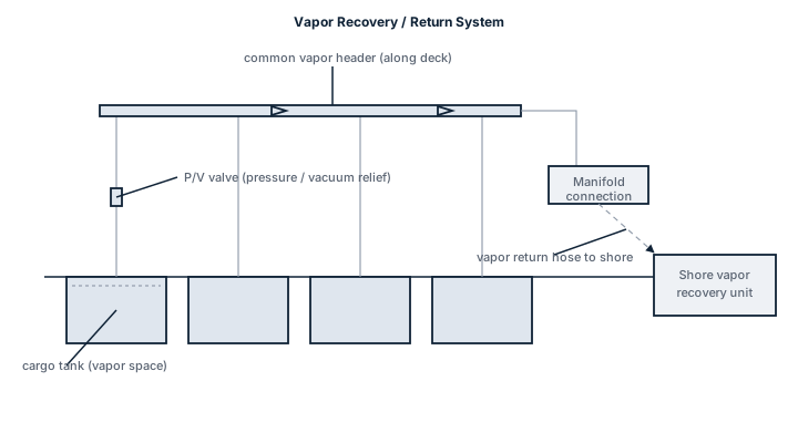
Main Components
Vapor manifold and shore connection
A dedicated line and flange, separate from the liquid cargo manifold, sized to carry the vapor volume displaced at maximum loading rate without pressuring the tanks above their design limit.
Vapor collection header
Runs along the tank deck, tying each cargo tank's vapor space into the common line through isolation valves, so individual tanks can be included or excluded from the recovery circuit.
Pressure control and relief
High-velocity vents and P/V valves remain in the system as the fallback if the shore vapor line cannot take the full flow or the connection is broken; a pressure/vacuum breaker protects the collection header itself from over- or under-pressure.
Flame screens and detonation arrestors
Fitted in the vapor line to stop a flame front from propagating back into the cargo tanks if an ignition source reaches the shore-side vapor system.
Selection and Sizing
Sizing is driven by the loading rate the ship is designed for, since vapor displacement tracks liquid loading volume almost directly.
- Maximum design loading rate per tank and in total, which sets the vapor line diameter and valve capacity needed.
- Allowable tank pressure range, since the vapor return path must keep pace with displacement without pushing tank pressure toward the P/V valve's set point.
- Cargo type and vapor characteristics; some cargoes carry vapor recovery requirements tied to their flash point or toxicity rather than pure convenience.
- Compatibility of the ship's manifold connection standard with the terminals the vessel regularly calls at.
Regulations and Class
MARPOL Annex VI and regional port regulations increasingly require vapor emission control at terminals handling volatile cargoes, which drives the shore-side requirement for a compatible ship connection; class rules for the cargo system require the P/V valves and venting arrangement to remain fully functional and independently capable of protecting the tanks regardless of whether a vapor return connection is in use. Flame arrestors and detonation arrestors in the vapor path are subject to type approval and periodic inspection under the society's cargo system survey requirements.
Typical Faults
| Fault | Cause | Consequence |
|---|---|---|
| Flame screen blockage | Fouling from polymerising cargo vapor or ice formation in cold conditions | Restricted vapor flow, rising tank pressure during loading, possible unplanned P/V valve lift |
| Isolation valve left shut | Tank not included in the vapor circuit at the pre-loading line-up | That tank vents locally instead of through the recovery line, undermining the terminal's emission commitment |
| Manifold connection mismatch | Ship and shore vapor connections use different standards or gaskets | Delayed cargo operation or a connection made with an unsuitable adapter |
| Overpressure during loading | Vapor return line undersized or restricted relative to actual loading rate | Tank pressure rises toward the P/V valve set point, forcing a reduced loading rate |
What to Look for in a Supplier
- Documentation of vapor line capacity against the ship's stated maximum loading rate, not a generic size match.
- Flame and detonation arrestor type approval certificates specific to the cargo range the ship carries.
- Manifold connection dimensions matched to the terminals in the vessel's trading pattern.
- Clear maintenance and inspection intervals for flame screens, which foul faster than most crews expect.
Never treat the vapor return connection as a substitute for watching tank pressure during loading; if the shore side cannot keep pace, the ship's own P/V valves are still what stands between the tank and an overpressure, so the loading rate has to come down, not the vigilance.