What to check on a Cargo Pump (Centrifugal, Pumproom).
A pumproom centrifugal cargo pump is driven from outside the hazardous space: the impeller sits low in the pumproom, but the steam turbine or electric motor that turns it sits in the engine room, connected through a long vertical shaft that passes through a gas-tight bulkhead gland. That single arrangement separates it from a deepwell pump, where the motor rides on top of the column inside the tank, and from a submersible pump, where the whole unit is immersed in the cargo. The bulkhead penetration gives easier maintenance access to…
What sets this pump apart
A pumproom centrifugal cargo pump is driven from outside the hazardous space: the impeller sits low in the pumproom, but the steam turbine or electric motor that turns it sits in the engine room, connected through a long vertical shaft that passes through a gas-tight bulkhead gland. That single arrangement separates it from a deepwell pump, where the motor rides on top of the column inside the tank, and from a submersible pump, where the whole unit is immersed in the cargo. The bulkhead penetration gives easier maintenance access to the driver but adds one more sealing point that can pass vapour into the engine room if it is neglected.
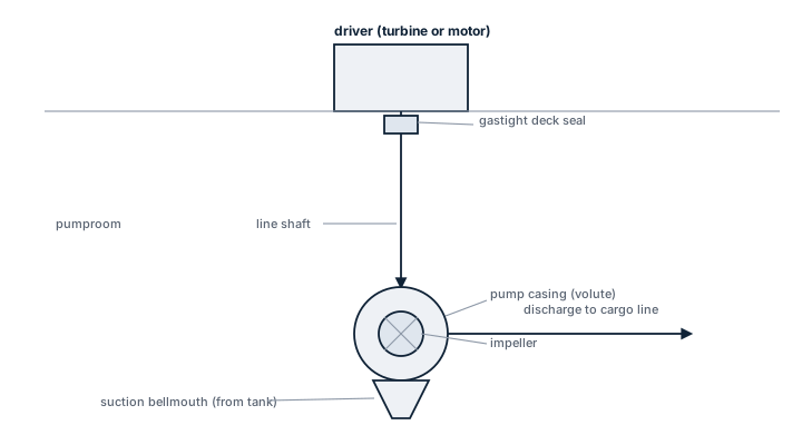
Main components
Casing and impeller
Single or multi-stage centrifugal casing, usually duplex or austenitic stainless steel for corrosive or aggressive cargoes, carbon steel with a protective coating for cleaner products. Impeller trim (diameter and vane profile) sets the duty point on the pump curve.
Vertical line shaft and bearings
A long shaft, supported by intermediate line shaft bearings, connects the driver to the pump. Bearings are usually product- or water-lubricated and are the first place misalignment shows up as vibration.
Bulkhead gland
The seal where the shaft crosses from pumproom to engine room, either a mechanical seal or a packed gland. This is a designated gas-hazard boundary and is monitored accordingly.
Driver
Steam turbine, common on older and larger tankers because it needs no electrical certification in the pumproom, or a variable-speed electric motor located in a non-hazardous area, coupled through the same vertical shaft.
Suction bell and strum box
Strainer at the tank suction that keeps debris and scale out of the impeller. Stripping arrangements, eductors or a dedicated stripping pump, handle the last cargo the main pump cannot lift once suction breaks.
Selection and sizing
Sizing runs off capacity, typically several hundred to well over a thousand cubic metres per hour per pump on a product or crude tanker, total developed head against manifold back-pressure and shore line resistance, and NPSH available at minimum tank level versus NPSH required by the pump. That last figure usually limits how far a tank can be stripped by the main pump before switching to eductors. Cargo viscosity and vapour pressure at loading temperature also set limits: a viscous or high-vapour-pressure cargo needs a flatter curve and more NPSH margin than the pump's water-test curve suggests. Most tankers fit one pump per cargo tank group so segregated grades can be discharged in parallel.
Regulations and class
The pumproom is a hazardous space under SOLAS Ch. II-2 and, where applicable, the IBC Code, with mechanical ventilation running continuously in port and gas detection at the entrance and at the bulkhead gland. Class rules require periodic survey of the shaft seal and bearings, and the bulkhead penetration is a specific item on annual and special survey checklists. Electric motor drivers in the engine room must still satisfy the certification appropriate to their proximity to the hazardous boundary.
Typical faults
- Bulkhead gland wear -- loses its seal over time; the consequence is vapour migration into the engine room, which is why gas detection sits right at that point.
- Cavitation from insufficient NPSH -- usually from stripping too low a tank level or a blocked strum box; the consequence is impeller and casing erosion and a sharp drop in delivered capacity.
- Line shaft misalignment -- from bearing wear or a shifted foundation; the consequence is vibration that accelerates bearing failure and can eventually crack the shaft.
- Impeller wear from abrasive or corrosive cargo -- the consequence is falling head and capacity even though the pump still runs smoothly.
What to look for in a supplier
- Casing and impeller material actually matched to the cargo slate the vessel trades, not a generic stainless specification.
- A bulkhead seal design with a proven service record and accessible spares.
- Documented pump curves at the viscosities and temperatures the vessel actually loads, not only water curves.
- Line shaft bearing spares available without a long lead time, since a bearing failure can take a pump out of service mid-voyage.
Treat the bulkhead gland like a class item every voyage, not only at survey -- a slow vapour leak there is one of the few cargo pump faults that turns into a safety case rather than a maintenance job.