Smoke Detector
A ship's smoke detector is chosen by fire behaviour, not brand: optical heads catch smouldering, particle-heavy fires early, ionisation heads react faster to open flame with little smoke, and picking the wrong type for a space leaves a real blind spot in the detection system.
Read more — Smoke Detector explained ▾
What distinguishes this detector type
Point-type smoke detectors used on board fall into two working principles. Optical (photoelectric) detectors shine an infrared beam across a sensing chamber and measure light scattered by smoke particles; they respond well to the dense, visible smoke typical of smouldering cable insulation, upholstery or slow-burning solids. Ionisation detectors use a small radioactive source to ionise air in the chamber and measure the drop in current when smoke particles interfere with that ionised flow; they respond faster to the fine, largely invisible particles thrown off by fast-flaming fires with little visible smoke, such as burning fuel or paper. Multi-criteria detectors combine a smoke sensor with a heat or CO sensor and vote between them to cut false alarms, at the cost of a slower response in a genuine fast fire.
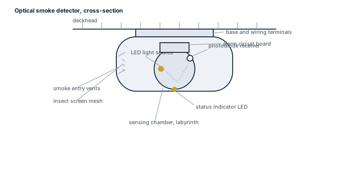
Main components
Sensing chamber
The optical or ionisation element itself, protected by an insect screen and a light trap or ionisation chamber housing. This is the part that ages: dust and salt-laden air gradually raise the baseline signal until the head drifts into false alarm territory.
Detector base and loop wiring
Plugs into a fixed base wired into an addressable or conventional loop back to the fire panel. Addressable bases carry an individual address so the panel reports the exact detector, not just the zone.
Fire panel interface
Processes the analogue signal, applies drift compensation and raises alarm, pre-alarm or fault at the bridge panel and any repeater panels.
Selection and placement
Type selection follows the fire risk of the space, not a fixed rule for the whole ship:
- Machinery spaces and areas with oil mist: heat detectors or multi-criteria units, since smoke detectors alone false-alarm on normal engine room haze.
- Accommodation, control rooms, cable trunks: optical smoke detectors are the default.
- Galleys and spaces with cooking fumes or steam: heat detectors or specially rated smoke detectors to avoid nuisance alarms.
- Coverage area per detector, ceiling height and beam obstructions all affect spacing and must follow the fire detection system's approved layout drawing, not a generic ceiling grid.
Regulations and class
SOLAS Chapter II-2 requires fixed fire detection and alarm systems in specified spaces depending on ship type, and the detectors themselves must meet the applicable IMO performance standard for shipborne fire detection equipment. Class rules require the system to be tested and the individual detector heads to be functionally tested at survey intervals set by the classification society, with sensitivity drift checked against the manufacturer's data. A detector that has drifted out of its calibrated window is treated as a fault, not left in service on the assumption it "still works".
Typical faults
| Fault | Cause | Consequence |
|---|---|---|
| Nuisance alarms | Dust or salt build-up in the chamber, insect ingress, wrong type for the space | Crew starts isolating or ignoring zones, defeating the system's purpose |
| No alarm on test | Corroded base contacts, broken loop wiring, detector not seated | Real fire in that space goes undetected until it is visible or smelt |
| Ground fault on loop | Chafed cable at a bulkhead penetration, moisture ingress in a junction box | Panel may isolate part of the loop, dropping several detectors at once |
| Sensitivity drift flagged by panel | Ageing sensing element, contamination | Detector due for cleaning or replacement before it fails outright |
What to look for in a supplier
- Type approval certificate matching the specific detector model, not just the product family.
- Compatibility confirmed with the existing fire panel's protocol - addressable loops are not interchangeable between panel manufacturers.
- Traceable batch and manufacture date, since sensing elements have a service life independent of whether they have triggered an alarm.
- Availability of the matching base, since heads and bases from different ranges of the same maker are not always compatible.
When a detector keeps false-alarming, replace or clean it rather than isolating the zone on the panel - an isolated zone is a zone with no fire protection at all, and it is easy to forget it was ever isolated.

14 manufacturers · 260 models
Hochiki Marine
67 ✓ 58 verified- Area: Detector Optical Window ObstructionCheck: Visually inspect detector lens and chamber for dust, insect contamination, or corrosion buildup. Clean or replace detector if optical transmission is compromised (use magnifying glass for small particulates).
- Area: Sensitivity Drift and CalibrationCheck: Perform semi-annual sensitivity testing using manufacturer-approved calibration tools (e.g., NSTT-C for SIJ-24 series). Verify detector responds within listed sensitivity range (typically 25%-70% obscuration for photoelectric). Replace if sensitivity cannot be recalibrated.
- Area: Installation Mounting and AlignmentCheck: Verify detectors are properly seated in bases (confirm clockwise twist-lock engagement). For beam detectors, confirm alignment within reflector center using motorized alignment verification. Check mounting hardware security and absence of vibration-induced looseness.
- Area: Electrical Continuity and Base ContactCheck: Verify electrical connections at detector base and wiring terminals. Test continuity to control panel. For conventional detectors, confirm 24VDC supply voltage at detector head. For addressable detectors, test SCI loop continuity and polling response.
- Area: Environmental Interference and False AlarmsCheck: Inspect for sources of nuisance triggers: proximity to HVAC ducts, direct sunlight on beam detectors, steam/condensation sources near smoke detectors, or electromagnetic interference near addressable loops. Reposition detectors or install optical filters as needed per EN54 standards.
Typ-universelle Inspektionspunkte fuer Fire Detection Systems (verifiziert, 2026-06).
- Area: Detector Optical Window ObstructionCheck: Visually inspect detector lens and chamber for dust, insect contamination, or corrosion buildup. Clean or replace detector if optical transmission is compromised (use magnifying glass for small particulates).
- Area: Sensitivity Drift and CalibrationCheck: Perform semi-annual sensitivity testing using manufacturer-approved calibration tools (e.g., NSTT-C for SIJ-24 series). Verify detector responds within listed sensitivity range (typically 25%-70% obscuration for photoelectric). Replace if sensitivity cannot be recalibrated.
- Area: Installation Mounting and AlignmentCheck: Verify detectors are properly seated in bases (confirm clockwise twist-lock engagement). For beam detectors, confirm alignment within reflector center using motorized alignment verification. Check mounting hardware security and absence of vibration-induced looseness.
- Area: Electrical Continuity and Base ContactCheck: Verify electrical connections at detector base and wiring terminals. Test continuity to control panel. For conventional detectors, confirm 24VDC supply voltage at detector head. For addressable detectors, test SCI loop continuity and polling response.
- Area: Environmental Interference and False AlarmsCheck: Inspect for sources of nuisance triggers: proximity to HVAC ducts, direct sunlight on beam detectors, steam/condensation sources near smoke detectors, or electromagnetic interference near addressable loops. Reposition detectors or install optical filters as needed per EN54 standards.
Typ-universelle Inspektionspunkte fuer Fire Detection Systems (verifiziert, 2026-06).
- Area: Detector Optical Window ObstructionCheck: Visually inspect detector lens and chamber for dust, insect contamination, or corrosion buildup. Clean or replace detector if optical transmission is compromised (use magnifying glass for small particulates).
- Area: Sensitivity Drift and CalibrationCheck: Perform semi-annual sensitivity testing using manufacturer-approved calibration tools (e.g., NSTT-C for SIJ-24 series). Verify detector responds within listed sensitivity range (typically 25%-70% obscuration for photoelectric). Replace if sensitivity cannot be recalibrated.
- Area: Installation Mounting and AlignmentCheck: Verify detectors are properly seated in bases (confirm clockwise twist-lock engagement). For beam detectors, confirm alignment within reflector center using motorized alignment verification. Check mounting hardware security and absence of vibration-induced looseness.
- Area: Electrical Continuity and Base ContactCheck: Verify electrical connections at detector base and wiring terminals. Test continuity to control panel. For conventional detectors, confirm 24VDC supply voltage at detector head. For addressable detectors, test SCI loop continuity and polling response.
- Area: Environmental Interference and False AlarmsCheck: Inspect for sources of nuisance triggers: proximity to HVAC ducts, direct sunlight on beam detectors, steam/condensation sources near smoke detectors, or electromagnetic interference near addressable loops. Reposition detectors or install optical filters as needed per EN54 standards.
Typ-universelle Inspektionspunkte fuer Fire Detection Systems (verifiziert, 2026-06).
- Area: Detector Optical Window ObstructionCheck: Visually inspect detector lens and chamber for dust, insect contamination, or corrosion buildup. Clean or replace detector if optical transmission is compromised (use magnifying glass for small particulates).
- Area: Sensitivity Drift and CalibrationCheck: Perform semi-annual sensitivity testing using manufacturer-approved calibration tools (e.g., NSTT-C for SIJ-24 series). Verify detector responds within listed sensitivity range (typically 25%-70% obscuration for photoelectric). Replace if sensitivity cannot be recalibrated.
- Area: Installation Mounting and AlignmentCheck: Verify detectors are properly seated in bases (confirm clockwise twist-lock engagement). For beam detectors, confirm alignment within reflector center using motorized alignment verification. Check mounting hardware security and absence of vibration-induced looseness.
- Area: Electrical Continuity and Base ContactCheck: Verify electrical connections at detector base and wiring terminals. Test continuity to control panel. For conventional detectors, confirm 24VDC supply voltage at detector head. For addressable detectors, test SCI loop continuity and polling response.
- Area: Environmental Interference and False AlarmsCheck: Inspect for sources of nuisance triggers: proximity to HVAC ducts, direct sunlight on beam detectors, steam/condensation sources near smoke detectors, or electromagnetic interference near addressable loops. Reposition detectors or install optical filters as needed per EN54 standards.
Typ-universelle Inspektionspunkte fuer Fire Detection Systems (verifiziert, 2026-06).
- Area: Detector Optical Window ObstructionCheck: Visually inspect detector lens and chamber for dust, insect contamination, or corrosion buildup. Clean or replace detector if optical transmission is compromised (use magnifying glass for small particulates).
- Area: Sensitivity Drift and CalibrationCheck: Perform semi-annual sensitivity testing using manufacturer-approved calibration tools (e.g., NSTT-C for SIJ-24 series). Verify detector responds within listed sensitivity range (typically 25%-70% obscuration for photoelectric). Replace if sensitivity cannot be recalibrated.
- Area: Installation Mounting and AlignmentCheck: Verify detectors are properly seated in bases (confirm clockwise twist-lock engagement). For beam detectors, confirm alignment within reflector center using motorized alignment verification. Check mounting hardware security and absence of vibration-induced looseness.
- Area: Electrical Continuity and Base ContactCheck: Verify electrical connections at detector base and wiring terminals. Test continuity to control panel. For conventional detectors, confirm 24VDC supply voltage at detector head. For addressable detectors, test SCI loop continuity and polling response.
- Area: Environmental Interference and False AlarmsCheck: Inspect for sources of nuisance triggers: proximity to HVAC ducts, direct sunlight on beam detectors, steam/condensation sources near smoke detectors, or electromagnetic interference near addressable loops. Reposition detectors or install optical filters as needed per EN54 standards.
Typ-universelle Inspektionspunkte fuer Fire Detection Systems (verifiziert, 2026-06).
- Area: Detector Optical Window ObstructionCheck: Visually inspect detector lens and chamber for dust, insect contamination, or corrosion buildup. Clean or replace detector if optical transmission is compromised (use magnifying glass for small particulates).
- Area: Sensitivity Drift and CalibrationCheck: Perform semi-annual sensitivity testing using manufacturer-approved calibration tools (e.g., NSTT-C for SIJ-24 series). Verify detector responds within listed sensitivity range (typically 25%-70% obscuration for photoelectric). Replace if sensitivity cannot be recalibrated.
- Area: Installation Mounting and AlignmentCheck: Verify detectors are properly seated in bases (confirm clockwise twist-lock engagement). For beam detectors, confirm alignment within reflector center using motorized alignment verification. Check mounting hardware security and absence of vibration-induced looseness.
- Area: Electrical Continuity and Base ContactCheck: Verify electrical connections at detector base and wiring terminals. Test continuity to control panel. For conventional detectors, confirm 24VDC supply voltage at detector head. For addressable detectors, test SCI loop continuity and polling response.
- Area: Environmental Interference and False AlarmsCheck: Inspect for sources of nuisance triggers: proximity to HVAC ducts, direct sunlight on beam detectors, steam/condensation sources near smoke detectors, or electromagnetic interference near addressable loops. Reposition detectors or install optical filters as needed per EN54 standards.
Typ-universelle Inspektionspunkte fuer Fire Detection Systems (verifiziert, 2026-06).
- Area: Detector Optical Window ObstructionCheck: Visually inspect detector lens and chamber for dust, insect contamination, or corrosion buildup. Clean or replace detector if optical transmission is compromised (use magnifying glass for small particulates).
- Area: Sensitivity Drift and CalibrationCheck: Perform semi-annual sensitivity testing using manufacturer-approved calibration tools (e.g., NSTT-C for SIJ-24 series). Verify detector responds within listed sensitivity range (typically 25%-70% obscuration for photoelectric). Replace if sensitivity cannot be recalibrated.
- Area: Installation Mounting and AlignmentCheck: Verify detectors are properly seated in bases (confirm clockwise twist-lock engagement). For beam detectors, confirm alignment within reflector center using motorized alignment verification. Check mounting hardware security and absence of vibration-induced looseness.
- Area: Electrical Continuity and Base ContactCheck: Verify electrical connections at detector base and wiring terminals. Test continuity to control panel. For conventional detectors, confirm 24VDC supply voltage at detector head. For addressable detectors, test SCI loop continuity and polling response.
- Area: Environmental Interference and False AlarmsCheck: Inspect for sources of nuisance triggers: proximity to HVAC ducts, direct sunlight on beam detectors, steam/condensation sources near smoke detectors, or electromagnetic interference near addressable loops. Reposition detectors or install optical filters as needed per EN54 standards.
Typ-universelle Inspektionspunkte fuer Fire Detection Systems (verifiziert, 2026-06).
- Area: Detector Optical Window ObstructionCheck: Visually inspect detector lens and chamber for dust, insect contamination, or corrosion buildup. Clean or replace detector if optical transmission is compromised (use magnifying glass for small particulates).
- Area: Sensitivity Drift and CalibrationCheck: Perform semi-annual sensitivity testing using manufacturer-approved calibration tools (e.g., NSTT-C for SIJ-24 series). Verify detector responds within listed sensitivity range (typically 25%-70% obscuration for photoelectric). Replace if sensitivity cannot be recalibrated.
- Area: Installation Mounting and AlignmentCheck: Verify detectors are properly seated in bases (confirm clockwise twist-lock engagement). For beam detectors, confirm alignment within reflector center using motorized alignment verification. Check mounting hardware security and absence of vibration-induced looseness.
- Area: Electrical Continuity and Base ContactCheck: Verify electrical connections at detector base and wiring terminals. Test continuity to control panel. For conventional detectors, confirm 24VDC supply voltage at detector head. For addressable detectors, test SCI loop continuity and polling response.
- Area: Environmental Interference and False AlarmsCheck: Inspect for sources of nuisance triggers: proximity to HVAC ducts, direct sunlight on beam detectors, steam/condensation sources near smoke detectors, or electromagnetic interference near addressable loops. Reposition detectors or install optical filters as needed per EN54 standards.
Typ-universelle Inspektionspunkte fuer Fire Detection Systems (verifiziert, 2026-06).
- Area: Detector Optical Window ObstructionCheck: Visually inspect detector lens and chamber for dust, insect contamination, or corrosion buildup. Clean or replace detector if optical transmission is compromised (use magnifying glass for small particulates).
- Area: Sensitivity Drift and CalibrationCheck: Perform semi-annual sensitivity testing using manufacturer-approved calibration tools (e.g., NSTT-C for SIJ-24 series). Verify detector responds within listed sensitivity range (typically 25%-70% obscuration for photoelectric). Replace if sensitivity cannot be recalibrated.
- Area: Installation Mounting and AlignmentCheck: Verify detectors are properly seated in bases (confirm clockwise twist-lock engagement). For beam detectors, confirm alignment within reflector center using motorized alignment verification. Check mounting hardware security and absence of vibration-induced looseness.
- Area: Electrical Continuity and Base ContactCheck: Verify electrical connections at detector base and wiring terminals. Test continuity to control panel. For conventional detectors, confirm 24VDC supply voltage at detector head. For addressable detectors, test SCI loop continuity and polling response.
- Area: Environmental Interference and False AlarmsCheck: Inspect for sources of nuisance triggers: proximity to HVAC ducts, direct sunlight on beam detectors, steam/condensation sources near smoke detectors, or electromagnetic interference near addressable loops. Reposition detectors or install optical filters as needed per EN54 standards.
Typ-universelle Inspektionspunkte fuer Fire Detection Systems (verifiziert, 2026-06).
- Area: Detector Optical Window ObstructionCheck: Visually inspect detector lens and chamber for dust, insect contamination, or corrosion buildup. Clean or replace detector if optical transmission is compromised (use magnifying glass for small particulates).
- Area: Sensitivity Drift and CalibrationCheck: Perform semi-annual sensitivity testing using manufacturer-approved calibration tools (e.g., NSTT-C for SIJ-24 series). Verify detector responds within listed sensitivity range (typically 25%-70% obscuration for photoelectric). Replace if sensitivity cannot be recalibrated.
- Area: Installation Mounting and AlignmentCheck: Verify detectors are properly seated in bases (confirm clockwise twist-lock engagement). For beam detectors, confirm alignment within reflector center using motorized alignment verification. Check mounting hardware security and absence of vibration-induced looseness.
- Area: Electrical Continuity and Base ContactCheck: Verify electrical connections at detector base and wiring terminals. Test continuity to control panel. For conventional detectors, confirm 24VDC supply voltage at detector head. For addressable detectors, test SCI loop continuity and polling response.
- Area: Environmental Interference and False AlarmsCheck: Inspect for sources of nuisance triggers: proximity to HVAC ducts, direct sunlight on beam detectors, steam/condensation sources near smoke detectors, or electromagnetic interference near addressable loops. Reposition detectors or install optical filters as needed per EN54 standards.
Typ-universelle Inspektionspunkte fuer Fire Detection Systems (verifiziert, 2026-06).
- Area: Detector Optical Window ObstructionCheck: Visually inspect detector lens and chamber for dust, insect contamination, or corrosion buildup. Clean or replace detector if optical transmission is compromised (use magnifying glass for small particulates).
- Area: Sensitivity Drift and CalibrationCheck: Perform semi-annual sensitivity testing using manufacturer-approved calibration tools (e.g., NSTT-C for SIJ-24 series). Verify detector responds within listed sensitivity range (typically 25%-70% obscuration for photoelectric). Replace if sensitivity cannot be recalibrated.
- Area: Installation Mounting and AlignmentCheck: Verify detectors are properly seated in bases (confirm clockwise twist-lock engagement). For beam detectors, confirm alignment within reflector center using motorized alignment verification. Check mounting hardware security and absence of vibration-induced looseness.
- Area: Electrical Continuity and Base ContactCheck: Verify electrical connections at detector base and wiring terminals. Test continuity to control panel. For conventional detectors, confirm 24VDC supply voltage at detector head. For addressable detectors, test SCI loop continuity and polling response.
- Area: Environmental Interference and False AlarmsCheck: Inspect for sources of nuisance triggers: proximity to HVAC ducts, direct sunlight on beam detectors, steam/condensation sources near smoke detectors, or electromagnetic interference near addressable loops. Reposition detectors or install optical filters as needed per EN54 standards.
Typ-universelle Inspektionspunkte fuer Fire Detection Systems (verifiziert, 2026-06).
- Area: Detector Optical Window ObstructionCheck: Visually inspect detector lens and chamber for dust, insect contamination, or corrosion buildup. Clean or replace detector if optical transmission is compromised (use magnifying glass for small particulates).
- Area: Sensitivity Drift and CalibrationCheck: Perform semi-annual sensitivity testing using manufacturer-approved calibration tools (e.g., NSTT-C for SIJ-24 series). Verify detector responds within listed sensitivity range (typically 25%-70% obscuration for photoelectric). Replace if sensitivity cannot be recalibrated.
- Area: Installation Mounting and AlignmentCheck: Verify detectors are properly seated in bases (confirm clockwise twist-lock engagement). For beam detectors, confirm alignment within reflector center using motorized alignment verification. Check mounting hardware security and absence of vibration-induced looseness.
- Area: Electrical Continuity and Base ContactCheck: Verify electrical connections at detector base and wiring terminals. Test continuity to control panel. For conventional detectors, confirm 24VDC supply voltage at detector head. For addressable detectors, test SCI loop continuity and polling response.
- Area: Environmental Interference and False AlarmsCheck: Inspect for sources of nuisance triggers: proximity to HVAC ducts, direct sunlight on beam detectors, steam/condensation sources near smoke detectors, or electromagnetic interference near addressable loops. Reposition detectors or install optical filters as needed per EN54 standards.
Typ-universelle Inspektionspunkte fuer Fire Detection Systems (verifiziert, 2026-06).
- Area: Detector Optical Window ObstructionCheck: Visually inspect detector lens and chamber for dust, insect contamination, or corrosion buildup. Clean or replace detector if optical transmission is compromised (use magnifying glass for small particulates).
- Area: Sensitivity Drift and CalibrationCheck: Perform semi-annual sensitivity testing using manufacturer-approved calibration tools (e.g., NSTT-C for SIJ-24 series). Verify detector responds within listed sensitivity range (typically 25%-70% obscuration for photoelectric). Replace if sensitivity cannot be recalibrated.
- Area: Installation Mounting and AlignmentCheck: Verify detectors are properly seated in bases (confirm clockwise twist-lock engagement). For beam detectors, confirm alignment within reflector center using motorized alignment verification. Check mounting hardware security and absence of vibration-induced looseness.
- Area: Electrical Continuity and Base ContactCheck: Verify electrical connections at detector base and wiring terminals. Test continuity to control panel. For conventional detectors, confirm 24VDC supply voltage at detector head. For addressable detectors, test SCI loop continuity and polling response.
- Area: Environmental Interference and False AlarmsCheck: Inspect for sources of nuisance triggers: proximity to HVAC ducts, direct sunlight on beam detectors, steam/condensation sources near smoke detectors, or electromagnetic interference near addressable loops. Reposition detectors or install optical filters as needed per EN54 standards.
Typ-universelle Inspektionspunkte fuer Fire Detection Systems (verifiziert, 2026-06).
- Area: Detector Optical Window ObstructionCheck: Visually inspect detector lens and chamber for dust, insect contamination, or corrosion buildup. Clean or replace detector if optical transmission is compromised (use magnifying glass for small particulates).
- Area: Sensitivity Drift and CalibrationCheck: Perform semi-annual sensitivity testing using manufacturer-approved calibration tools (e.g., NSTT-C for SIJ-24 series). Verify detector responds within listed sensitivity range (typically 25%-70% obscuration for photoelectric). Replace if sensitivity cannot be recalibrated.
- Area: Installation Mounting and AlignmentCheck: Verify detectors are properly seated in bases (confirm clockwise twist-lock engagement). For beam detectors, confirm alignment within reflector center using motorized alignment verification. Check mounting hardware security and absence of vibration-induced looseness.
- Area: Electrical Continuity and Base ContactCheck: Verify electrical connections at detector base and wiring terminals. Test continuity to control panel. For conventional detectors, confirm 24VDC supply voltage at detector head. For addressable detectors, test SCI loop continuity and polling response.
- Area: Environmental Interference and False AlarmsCheck: Inspect for sources of nuisance triggers: proximity to HVAC ducts, direct sunlight on beam detectors, steam/condensation sources near smoke detectors, or electromagnetic interference near addressable loops. Reposition detectors or install optical filters as needed per EN54 standards.
Typ-universelle Inspektionspunkte fuer Fire Detection Systems (verifiziert, 2026-06).
- Area: Detector Optical Window ObstructionCheck: Visually inspect detector lens and chamber for dust, insect contamination, or corrosion buildup. Clean or replace detector if optical transmission is compromised (use magnifying glass for small particulates).
- Area: Sensitivity Drift and CalibrationCheck: Perform semi-annual sensitivity testing using manufacturer-approved calibration tools (e.g., NSTT-C for SIJ-24 series). Verify detector responds within listed sensitivity range (typically 25%-70% obscuration for photoelectric). Replace if sensitivity cannot be recalibrated.
- Area: Installation Mounting and AlignmentCheck: Verify detectors are properly seated in bases (confirm clockwise twist-lock engagement). For beam detectors, confirm alignment within reflector center using motorized alignment verification. Check mounting hardware security and absence of vibration-induced looseness.
- Area: Electrical Continuity and Base ContactCheck: Verify electrical connections at detector base and wiring terminals. Test continuity to control panel. For conventional detectors, confirm 24VDC supply voltage at detector head. For addressable detectors, test SCI loop continuity and polling response.
- Area: Environmental Interference and False AlarmsCheck: Inspect for sources of nuisance triggers: proximity to HVAC ducts, direct sunlight on beam detectors, steam/condensation sources near smoke detectors, or electromagnetic interference near addressable loops. Reposition detectors or install optical filters as needed per EN54 standards.
Typ-universelle Inspektionspunkte fuer Fire Detection Systems (verifiziert, 2026-06).
- Area: Detector Optical Window ObstructionCheck: Visually inspect detector lens and chamber for dust, insect contamination, or corrosion buildup. Clean or replace detector if optical transmission is compromised (use magnifying glass for small particulates).
- Area: Sensitivity Drift and CalibrationCheck: Perform semi-annual sensitivity testing using manufacturer-approved calibration tools (e.g., NSTT-C for SIJ-24 series). Verify detector responds within listed sensitivity range (typically 25%-70% obscuration for photoelectric). Replace if sensitivity cannot be recalibrated.
- Area: Installation Mounting and AlignmentCheck: Verify detectors are properly seated in bases (confirm clockwise twist-lock engagement). For beam detectors, confirm alignment within reflector center using motorized alignment verification. Check mounting hardware security and absence of vibration-induced looseness.
- Area: Electrical Continuity and Base ContactCheck: Verify electrical connections at detector base and wiring terminals. Test continuity to control panel. For conventional detectors, confirm 24VDC supply voltage at detector head. For addressable detectors, test SCI loop continuity and polling response.
- Area: Environmental Interference and False AlarmsCheck: Inspect for sources of nuisance triggers: proximity to HVAC ducts, direct sunlight on beam detectors, steam/condensation sources near smoke detectors, or electromagnetic interference near addressable loops. Reposition detectors or install optical filters as needed per EN54 standards.
Typ-universelle Inspektionspunkte fuer Fire Detection Systems (verifiziert, 2026-06).
- Area: Detector Optical Window ObstructionCheck: Visually inspect detector lens and chamber for dust, insect contamination, or corrosion buildup. Clean or replace detector if optical transmission is compromised (use magnifying glass for small particulates).
- Area: Sensitivity Drift and CalibrationCheck: Perform semi-annual sensitivity testing using manufacturer-approved calibration tools (e.g., NSTT-C for SIJ-24 series). Verify detector responds within listed sensitivity range (typically 25%-70% obscuration for photoelectric). Replace if sensitivity cannot be recalibrated.
- Area: Installation Mounting and AlignmentCheck: Verify detectors are properly seated in bases (confirm clockwise twist-lock engagement). For beam detectors, confirm alignment within reflector center using motorized alignment verification. Check mounting hardware security and absence of vibration-induced looseness.
- Area: Electrical Continuity and Base ContactCheck: Verify electrical connections at detector base and wiring terminals. Test continuity to control panel. For conventional detectors, confirm 24VDC supply voltage at detector head. For addressable detectors, test SCI loop continuity and polling response.
- Area: Environmental Interference and False AlarmsCheck: Inspect for sources of nuisance triggers: proximity to HVAC ducts, direct sunlight on beam detectors, steam/condensation sources near smoke detectors, or electromagnetic interference near addressable loops. Reposition detectors or install optical filters as needed per EN54 standards.
Typ-universelle Inspektionspunkte fuer Fire Detection Systems (verifiziert, 2026-06).
- Area: Detector Optical Window ObstructionCheck: Visually inspect detector lens and chamber for dust, insect contamination, or corrosion buildup. Clean or replace detector if optical transmission is compromised (use magnifying glass for small particulates).
- Area: Sensitivity Drift and CalibrationCheck: Perform semi-annual sensitivity testing using manufacturer-approved calibration tools (e.g., NSTT-C for SIJ-24 series). Verify detector responds within listed sensitivity range (typically 25%-70% obscuration for photoelectric). Replace if sensitivity cannot be recalibrated.
- Area: Installation Mounting and AlignmentCheck: Verify detectors are properly seated in bases (confirm clockwise twist-lock engagement). For beam detectors, confirm alignment within reflector center using motorized alignment verification. Check mounting hardware security and absence of vibration-induced looseness.
- Area: Electrical Continuity and Base ContactCheck: Verify electrical connections at detector base and wiring terminals. Test continuity to control panel. For conventional detectors, confirm 24VDC supply voltage at detector head. For addressable detectors, test SCI loop continuity and polling response.
- Area: Environmental Interference and False AlarmsCheck: Inspect for sources of nuisance triggers: proximity to HVAC ducts, direct sunlight on beam detectors, steam/condensation sources near smoke detectors, or electromagnetic interference near addressable loops. Reposition detectors or install optical filters as needed per EN54 standards.
Typ-universelle Inspektionspunkte fuer Fire Detection Systems (verifiziert, 2026-06).
- Area: Detector Optical Window ObstructionCheck: Visually inspect detector lens and chamber for dust, insect contamination, or corrosion buildup. Clean or replace detector if optical transmission is compromised (use magnifying glass for small particulates).
- Area: Sensitivity Drift and CalibrationCheck: Perform semi-annual sensitivity testing using manufacturer-approved calibration tools (e.g., NSTT-C for SIJ-24 series). Verify detector responds within listed sensitivity range (typically 25%-70% obscuration for photoelectric). Replace if sensitivity cannot be recalibrated.
- Area: Installation Mounting and AlignmentCheck: Verify detectors are properly seated in bases (confirm clockwise twist-lock engagement). For beam detectors, confirm alignment within reflector center using motorized alignment verification. Check mounting hardware security and absence of vibration-induced looseness.
- Area: Electrical Continuity and Base ContactCheck: Verify electrical connections at detector base and wiring terminals. Test continuity to control panel. For conventional detectors, confirm 24VDC supply voltage at detector head. For addressable detectors, test SCI loop continuity and polling response.
- Area: Environmental Interference and False AlarmsCheck: Inspect for sources of nuisance triggers: proximity to HVAC ducts, direct sunlight on beam detectors, steam/condensation sources near smoke detectors, or electromagnetic interference near addressable loops. Reposition detectors or install optical filters as needed per EN54 standards.
Typ-universelle Inspektionspunkte fuer Fire Detection Systems (verifiziert, 2026-06).
- Area: Detector Optical Window ObstructionCheck: Visually inspect detector lens and chamber for dust, insect contamination, or corrosion buildup. Clean or replace detector if optical transmission is compromised (use magnifying glass for small particulates).
- Area: Sensitivity Drift and CalibrationCheck: Perform semi-annual sensitivity testing using manufacturer-approved calibration tools (e.g., NSTT-C for SIJ-24 series). Verify detector responds within listed sensitivity range (typically 25%-70% obscuration for photoelectric). Replace if sensitivity cannot be recalibrated.
- Area: Installation Mounting and AlignmentCheck: Verify detectors are properly seated in bases (confirm clockwise twist-lock engagement). For beam detectors, confirm alignment within reflector center using motorized alignment verification. Check mounting hardware security and absence of vibration-induced looseness.
- Area: Electrical Continuity and Base ContactCheck: Verify electrical connections at detector base and wiring terminals. Test continuity to control panel. For conventional detectors, confirm 24VDC supply voltage at detector head. For addressable detectors, test SCI loop continuity and polling response.
- Area: Environmental Interference and False AlarmsCheck: Inspect for sources of nuisance triggers: proximity to HVAC ducts, direct sunlight on beam detectors, steam/condensation sources near smoke detectors, or electromagnetic interference near addressable loops. Reposition detectors or install optical filters as needed per EN54 standards.
Typ-universelle Inspektionspunkte fuer Fire Detection Systems (verifiziert, 2026-06).
- Area: Detector Optical Window ObstructionCheck: Visually inspect detector lens and chamber for dust, insect contamination, or corrosion buildup. Clean or replace detector if optical transmission is compromised (use magnifying glass for small particulates).
- Area: Sensitivity Drift and CalibrationCheck: Perform semi-annual sensitivity testing using manufacturer-approved calibration tools (e.g., NSTT-C for SIJ-24 series). Verify detector responds within listed sensitivity range (typically 25%-70% obscuration for photoelectric). Replace if sensitivity cannot be recalibrated.
- Area: Installation Mounting and AlignmentCheck: Verify detectors are properly seated in bases (confirm clockwise twist-lock engagement). For beam detectors, confirm alignment within reflector center using motorized alignment verification. Check mounting hardware security and absence of vibration-induced looseness.
- Area: Electrical Continuity and Base ContactCheck: Verify electrical connections at detector base and wiring terminals. Test continuity to control panel. For conventional detectors, confirm 24VDC supply voltage at detector head. For addressable detectors, test SCI loop continuity and polling response.
- Area: Environmental Interference and False AlarmsCheck: Inspect for sources of nuisance triggers: proximity to HVAC ducts, direct sunlight on beam detectors, steam/condensation sources near smoke detectors, or electromagnetic interference near addressable loops. Reposition detectors or install optical filters as needed per EN54 standards.
Typ-universelle Inspektionspunkte fuer Fire Detection Systems (verifiziert, 2026-06).
- Area: Detector Optical Window ObstructionCheck: Visually inspect detector lens and chamber for dust, insect contamination, or corrosion buildup. Clean or replace detector if optical transmission is compromised (use magnifying glass for small particulates).
- Area: Sensitivity Drift and CalibrationCheck: Perform semi-annual sensitivity testing using manufacturer-approved calibration tools (e.g., NSTT-C for SIJ-24 series). Verify detector responds within listed sensitivity range (typically 25%-70% obscuration for photoelectric). Replace if sensitivity cannot be recalibrated.
- Area: Installation Mounting and AlignmentCheck: Verify detectors are properly seated in bases (confirm clockwise twist-lock engagement). For beam detectors, confirm alignment within reflector center using motorized alignment verification. Check mounting hardware security and absence of vibration-induced looseness.
- Area: Electrical Continuity and Base ContactCheck: Verify electrical connections at detector base and wiring terminals. Test continuity to control panel. For conventional detectors, confirm 24VDC supply voltage at detector head. For addressable detectors, test SCI loop continuity and polling response.
- Area: Environmental Interference and False AlarmsCheck: Inspect for sources of nuisance triggers: proximity to HVAC ducts, direct sunlight on beam detectors, steam/condensation sources near smoke detectors, or electromagnetic interference near addressable loops. Reposition detectors or install optical filters as needed per EN54 standards.
Typ-universelle Inspektionspunkte fuer Fire Detection Systems (verifiziert, 2026-06).
- Area: Detector Optical Window ObstructionCheck: Visually inspect detector lens and chamber for dust, insect contamination, or corrosion buildup. Clean or replace detector if optical transmission is compromised (use magnifying glass for small particulates).
- Area: Sensitivity Drift and CalibrationCheck: Perform semi-annual sensitivity testing using manufacturer-approved calibration tools (e.g., NSTT-C for SIJ-24 series). Verify detector responds within listed sensitivity range (typically 25%-70% obscuration for photoelectric). Replace if sensitivity cannot be recalibrated.
- Area: Installation Mounting and AlignmentCheck: Verify detectors are properly seated in bases (confirm clockwise twist-lock engagement). For beam detectors, confirm alignment within reflector center using motorized alignment verification. Check mounting hardware security and absence of vibration-induced looseness.
- Area: Electrical Continuity and Base ContactCheck: Verify electrical connections at detector base and wiring terminals. Test continuity to control panel. For conventional detectors, confirm 24VDC supply voltage at detector head. For addressable detectors, test SCI loop continuity and polling response.
- Area: Environmental Interference and False AlarmsCheck: Inspect for sources of nuisance triggers: proximity to HVAC ducts, direct sunlight on beam detectors, steam/condensation sources near smoke detectors, or electromagnetic interference near addressable loops. Reposition detectors or install optical filters as needed per EN54 standards.
Typ-universelle Inspektionspunkte fuer Fire Detection Systems (verifiziert, 2026-06).
- Area: Detector Optical Window ObstructionCheck: Visually inspect detector lens and chamber for dust, insect contamination, or corrosion buildup. Clean or replace detector if optical transmission is compromised (use magnifying glass for small particulates).
- Area: Sensitivity Drift and CalibrationCheck: Perform semi-annual sensitivity testing using manufacturer-approved calibration tools (e.g., NSTT-C for SIJ-24 series). Verify detector responds within listed sensitivity range (typically 25%-70% obscuration for photoelectric). Replace if sensitivity cannot be recalibrated.
- Area: Installation Mounting and AlignmentCheck: Verify detectors are properly seated in bases (confirm clockwise twist-lock engagement). For beam detectors, confirm alignment within reflector center using motorized alignment verification. Check mounting hardware security and absence of vibration-induced looseness.
- Area: Electrical Continuity and Base ContactCheck: Verify electrical connections at detector base and wiring terminals. Test continuity to control panel. For conventional detectors, confirm 24VDC supply voltage at detector head. For addressable detectors, test SCI loop continuity and polling response.
- Area: Environmental Interference and False AlarmsCheck: Inspect for sources of nuisance triggers: proximity to HVAC ducts, direct sunlight on beam detectors, steam/condensation sources near smoke detectors, or electromagnetic interference near addressable loops. Reposition detectors or install optical filters as needed per EN54 standards.
Typ-universelle Inspektionspunkte fuer Fire Detection Systems (verifiziert, 2026-06).
- Area: Detector Optical Window ObstructionCheck: Visually inspect detector lens and chamber for dust, insect contamination, or corrosion buildup. Clean or replace detector if optical transmission is compromised (use magnifying glass for small particulates).
- Area: Sensitivity Drift and CalibrationCheck: Perform semi-annual sensitivity testing using manufacturer-approved calibration tools (e.g., NSTT-C for SIJ-24 series). Verify detector responds within listed sensitivity range (typically 25%-70% obscuration for photoelectric). Replace if sensitivity cannot be recalibrated.
- Area: Installation Mounting and AlignmentCheck: Verify detectors are properly seated in bases (confirm clockwise twist-lock engagement). For beam detectors, confirm alignment within reflector center using motorized alignment verification. Check mounting hardware security and absence of vibration-induced looseness.
- Area: Electrical Continuity and Base ContactCheck: Verify electrical connections at detector base and wiring terminals. Test continuity to control panel. For conventional detectors, confirm 24VDC supply voltage at detector head. For addressable detectors, test SCI loop continuity and polling response.
- Area: Environmental Interference and False AlarmsCheck: Inspect for sources of nuisance triggers: proximity to HVAC ducts, direct sunlight on beam detectors, steam/condensation sources near smoke detectors, or electromagnetic interference near addressable loops. Reposition detectors or install optical filters as needed per EN54 standards.
Typ-universelle Inspektionspunkte fuer Fire Detection Systems (verifiziert, 2026-06).
- Area: Detector Optical Window ObstructionCheck: Visually inspect detector lens and chamber for dust, insect contamination, or corrosion buildup. Clean or replace detector if optical transmission is compromised (use magnifying glass for small particulates).
- Area: Sensitivity Drift and CalibrationCheck: Perform semi-annual sensitivity testing using manufacturer-approved calibration tools (e.g., NSTT-C for SIJ-24 series). Verify detector responds within listed sensitivity range (typically 25%-70% obscuration for photoelectric). Replace if sensitivity cannot be recalibrated.
- Area: Installation Mounting and AlignmentCheck: Verify detectors are properly seated in bases (confirm clockwise twist-lock engagement). For beam detectors, confirm alignment within reflector center using motorized alignment verification. Check mounting hardware security and absence of vibration-induced looseness.
- Area: Electrical Continuity and Base ContactCheck: Verify electrical connections at detector base and wiring terminals. Test continuity to control panel. For conventional detectors, confirm 24VDC supply voltage at detector head. For addressable detectors, test SCI loop continuity and polling response.
- Area: Environmental Interference and False AlarmsCheck: Inspect for sources of nuisance triggers: proximity to HVAC ducts, direct sunlight on beam detectors, steam/condensation sources near smoke detectors, or electromagnetic interference near addressable loops. Reposition detectors or install optical filters as needed per EN54 standards.
Typ-universelle Inspektionspunkte fuer Fire Detection Systems (verifiziert, 2026-06).
- Area: Detector Optical Window ObstructionCheck: Visually inspect detector lens and chamber for dust, insect contamination, or corrosion buildup. Clean or replace detector if optical transmission is compromised (use magnifying glass for small particulates).
- Area: Sensitivity Drift and CalibrationCheck: Perform semi-annual sensitivity testing using manufacturer-approved calibration tools (e.g., NSTT-C for SIJ-24 series). Verify detector responds within listed sensitivity range (typically 25%-70% obscuration for photoelectric). Replace if sensitivity cannot be recalibrated.
- Area: Installation Mounting and AlignmentCheck: Verify detectors are properly seated in bases (confirm clockwise twist-lock engagement). For beam detectors, confirm alignment within reflector center using motorized alignment verification. Check mounting hardware security and absence of vibration-induced looseness.
- Area: Electrical Continuity and Base ContactCheck: Verify electrical connections at detector base and wiring terminals. Test continuity to control panel. For conventional detectors, confirm 24VDC supply voltage at detector head. For addressable detectors, test SCI loop continuity and polling response.
- Area: Environmental Interference and False AlarmsCheck: Inspect for sources of nuisance triggers: proximity to HVAC ducts, direct sunlight on beam detectors, steam/condensation sources near smoke detectors, or electromagnetic interference near addressable loops. Reposition detectors or install optical filters as needed per EN54 standards.
Typ-universelle Inspektionspunkte fuer Fire Detection Systems (verifiziert, 2026-06).
- Area: Detector Optical Window ObstructionCheck: Visually inspect detector lens and chamber for dust, insect contamination, or corrosion buildup. Clean or replace detector if optical transmission is compromised (use magnifying glass for small particulates).
- Area: Sensitivity Drift and CalibrationCheck: Perform semi-annual sensitivity testing using manufacturer-approved calibration tools (e.g., NSTT-C for SIJ-24 series). Verify detector responds within listed sensitivity range (typically 25%-70% obscuration for photoelectric). Replace if sensitivity cannot be recalibrated.
- Area: Installation Mounting and AlignmentCheck: Verify detectors are properly seated in bases (confirm clockwise twist-lock engagement). For beam detectors, confirm alignment within reflector center using motorized alignment verification. Check mounting hardware security and absence of vibration-induced looseness.
- Area: Electrical Continuity and Base ContactCheck: Verify electrical connections at detector base and wiring terminals. Test continuity to control panel. For conventional detectors, confirm 24VDC supply voltage at detector head. For addressable detectors, test SCI loop continuity and polling response.
- Area: Environmental Interference and False AlarmsCheck: Inspect for sources of nuisance triggers: proximity to HVAC ducts, direct sunlight on beam detectors, steam/condensation sources near smoke detectors, or electromagnetic interference near addressable loops. Reposition detectors or install optical filters as needed per EN54 standards.
Typ-universelle Inspektionspunkte fuer Fire Detection Systems (verifiziert, 2026-06).
- Area: Detector Optical Window ObstructionCheck: Visually inspect detector lens and chamber for dust, insect contamination, or corrosion buildup. Clean or replace detector if optical transmission is compromised (use magnifying glass for small particulates).
- Area: Sensitivity Drift and CalibrationCheck: Perform semi-annual sensitivity testing using manufacturer-approved calibration tools (e.g., NSTT-C for SIJ-24 series). Verify detector responds within listed sensitivity range (typically 25%-70% obscuration for photoelectric). Replace if sensitivity cannot be recalibrated.
- Area: Installation Mounting and AlignmentCheck: Verify detectors are properly seated in bases (confirm clockwise twist-lock engagement). For beam detectors, confirm alignment within reflector center using motorized alignment verification. Check mounting hardware security and absence of vibration-induced looseness.
- Area: Electrical Continuity and Base ContactCheck: Verify electrical connections at detector base and wiring terminals. Test continuity to control panel. For conventional detectors, confirm 24VDC supply voltage at detector head. For addressable detectors, test SCI loop continuity and polling response.
- Area: Environmental Interference and False AlarmsCheck: Inspect for sources of nuisance triggers: proximity to HVAC ducts, direct sunlight on beam detectors, steam/condensation sources near smoke detectors, or electromagnetic interference near addressable loops. Reposition detectors or install optical filters as needed per EN54 standards.
Typ-universelle Inspektionspunkte fuer Fire Detection Systems (verifiziert, 2026-06).
- Area: Detector Optical Window ObstructionCheck: Visually inspect detector lens and chamber for dust, insect contamination, or corrosion buildup. Clean or replace detector if optical transmission is compromised (use magnifying glass for small particulates).
- Area: Sensitivity Drift and CalibrationCheck: Perform semi-annual sensitivity testing using manufacturer-approved calibration tools (e.g., NSTT-C for SIJ-24 series). Verify detector responds within listed sensitivity range (typically 25%-70% obscuration for photoelectric). Replace if sensitivity cannot be recalibrated.
- Area: Installation Mounting and AlignmentCheck: Verify detectors are properly seated in bases (confirm clockwise twist-lock engagement). For beam detectors, confirm alignment within reflector center using motorized alignment verification. Check mounting hardware security and absence of vibration-induced looseness.
- Area: Electrical Continuity and Base ContactCheck: Verify electrical connections at detector base and wiring terminals. Test continuity to control panel. For conventional detectors, confirm 24VDC supply voltage at detector head. For addressable detectors, test SCI loop continuity and polling response.
- Area: Environmental Interference and False AlarmsCheck: Inspect for sources of nuisance triggers: proximity to HVAC ducts, direct sunlight on beam detectors, steam/condensation sources near smoke detectors, or electromagnetic interference near addressable loops. Reposition detectors or install optical filters as needed per EN54 standards.
Typ-universelle Inspektionspunkte fuer Fire Detection Systems (verifiziert, 2026-06).
- Area: Detector Optical Window ObstructionCheck: Visually inspect detector lens and chamber for dust, insect contamination, or corrosion buildup. Clean or replace detector if optical transmission is compromised (use magnifying glass for small particulates).
- Area: Sensitivity Drift and CalibrationCheck: Perform semi-annual sensitivity testing using manufacturer-approved calibration tools (e.g., NSTT-C for SIJ-24 series). Verify detector responds within listed sensitivity range (typically 25%-70% obscuration for photoelectric). Replace if sensitivity cannot be recalibrated.
- Area: Installation Mounting and AlignmentCheck: Verify detectors are properly seated in bases (confirm clockwise twist-lock engagement). For beam detectors, confirm alignment within reflector center using motorized alignment verification. Check mounting hardware security and absence of vibration-induced looseness.
- Area: Electrical Continuity and Base ContactCheck: Verify electrical connections at detector base and wiring terminals. Test continuity to control panel. For conventional detectors, confirm 24VDC supply voltage at detector head. For addressable detectors, test SCI loop continuity and polling response.
- Area: Environmental Interference and False AlarmsCheck: Inspect for sources of nuisance triggers: proximity to HVAC ducts, direct sunlight on beam detectors, steam/condensation sources near smoke detectors, or electromagnetic interference near addressable loops. Reposition detectors or install optical filters as needed per EN54 standards.
Typ-universelle Inspektionspunkte fuer Fire Detection Systems (verifiziert, 2026-06).
- Area: Detector Optical Window ObstructionCheck: Visually inspect detector lens and chamber for dust, insect contamination, or corrosion buildup. Clean or replace detector if optical transmission is compromised (use magnifying glass for small particulates).
- Area: Sensitivity Drift and CalibrationCheck: Perform semi-annual sensitivity testing using manufacturer-approved calibration tools (e.g., NSTT-C for SIJ-24 series). Verify detector responds within listed sensitivity range (typically 25%-70% obscuration for photoelectric). Replace if sensitivity cannot be recalibrated.
- Area: Installation Mounting and AlignmentCheck: Verify detectors are properly seated in bases (confirm clockwise twist-lock engagement). For beam detectors, confirm alignment within reflector center using motorized alignment verification. Check mounting hardware security and absence of vibration-induced looseness.
- Area: Electrical Continuity and Base ContactCheck: Verify electrical connections at detector base and wiring terminals. Test continuity to control panel. For conventional detectors, confirm 24VDC supply voltage at detector head. For addressable detectors, test SCI loop continuity and polling response.
- Area: Environmental Interference and False AlarmsCheck: Inspect for sources of nuisance triggers: proximity to HVAC ducts, direct sunlight on beam detectors, steam/condensation sources near smoke detectors, or electromagnetic interference near addressable loops. Reposition detectors or install optical filters as needed per EN54 standards.
Typ-universelle Inspektionspunkte fuer Fire Detection Systems (verifiziert, 2026-06).
- Area: Detector Optical Window ObstructionCheck: Visually inspect detector lens and chamber for dust, insect contamination, or corrosion buildup. Clean or replace detector if optical transmission is compromised (use magnifying glass for small particulates).
- Area: Sensitivity Drift and CalibrationCheck: Perform semi-annual sensitivity testing using manufacturer-approved calibration tools (e.g., NSTT-C for SIJ-24 series). Verify detector responds within listed sensitivity range (typically 25%-70% obscuration for photoelectric). Replace if sensitivity cannot be recalibrated.
- Area: Installation Mounting and AlignmentCheck: Verify detectors are properly seated in bases (confirm clockwise twist-lock engagement). For beam detectors, confirm alignment within reflector center using motorized alignment verification. Check mounting hardware security and absence of vibration-induced looseness.
- Area: Electrical Continuity and Base ContactCheck: Verify electrical connections at detector base and wiring terminals. Test continuity to control panel. For conventional detectors, confirm 24VDC supply voltage at detector head. For addressable detectors, test SCI loop continuity and polling response.
- Area: Environmental Interference and False AlarmsCheck: Inspect for sources of nuisance triggers: proximity to HVAC ducts, direct sunlight on beam detectors, steam/condensation sources near smoke detectors, or electromagnetic interference near addressable loops. Reposition detectors or install optical filters as needed per EN54 standards.
Typ-universelle Inspektionspunkte fuer Fire Detection Systems (verifiziert, 2026-06).
- Area: Detector Optical Window ObstructionCheck: Visually inspect detector lens and chamber for dust, insect contamination, or corrosion buildup. Clean or replace detector if optical transmission is compromised (use magnifying glass for small particulates).
- Area: Sensitivity Drift and CalibrationCheck: Perform semi-annual sensitivity testing using manufacturer-approved calibration tools (e.g., NSTT-C for SIJ-24 series). Verify detector responds within listed sensitivity range (typically 25%-70% obscuration for photoelectric). Replace if sensitivity cannot be recalibrated.
- Area: Installation Mounting and AlignmentCheck: Verify detectors are properly seated in bases (confirm clockwise twist-lock engagement). For beam detectors, confirm alignment within reflector center using motorized alignment verification. Check mounting hardware security and absence of vibration-induced looseness.
- Area: Electrical Continuity and Base ContactCheck: Verify electrical connections at detector base and wiring terminals. Test continuity to control panel. For conventional detectors, confirm 24VDC supply voltage at detector head. For addressable detectors, test SCI loop continuity and polling response.
- Area: Environmental Interference and False AlarmsCheck: Inspect for sources of nuisance triggers: proximity to HVAC ducts, direct sunlight on beam detectors, steam/condensation sources near smoke detectors, or electromagnetic interference near addressable loops. Reposition detectors or install optical filters as needed per EN54 standards.
Typ-universelle Inspektionspunkte fuer Fire Detection Systems (verifiziert, 2026-06).
- Area: Detector Optical Window ObstructionCheck: Visually inspect detector lens and chamber for dust, insect contamination, or corrosion buildup. Clean or replace detector if optical transmission is compromised (use magnifying glass for small particulates).
- Area: Sensitivity Drift and CalibrationCheck: Perform semi-annual sensitivity testing using manufacturer-approved calibration tools (e.g., NSTT-C for SIJ-24 series). Verify detector responds within listed sensitivity range (typically 25%-70% obscuration for photoelectric). Replace if sensitivity cannot be recalibrated.
- Area: Installation Mounting and AlignmentCheck: Verify detectors are properly seated in bases (confirm clockwise twist-lock engagement). For beam detectors, confirm alignment within reflector center using motorized alignment verification. Check mounting hardware security and absence of vibration-induced looseness.
- Area: Electrical Continuity and Base ContactCheck: Verify electrical connections at detector base and wiring terminals. Test continuity to control panel. For conventional detectors, confirm 24VDC supply voltage at detector head. For addressable detectors, test SCI loop continuity and polling response.
- Area: Environmental Interference and False AlarmsCheck: Inspect for sources of nuisance triggers: proximity to HVAC ducts, direct sunlight on beam detectors, steam/condensation sources near smoke detectors, or electromagnetic interference near addressable loops. Reposition detectors or install optical filters as needed per EN54 standards.
Typ-universelle Inspektionspunkte fuer Fire Detection Systems (verifiziert, 2026-06).
- Area: Detector Optical Window ObstructionCheck: Visually inspect detector lens and chamber for dust, insect contamination, or corrosion buildup. Clean or replace detector if optical transmission is compromised (use magnifying glass for small particulates).
- Area: Sensitivity Drift and CalibrationCheck: Perform semi-annual sensitivity testing using manufacturer-approved calibration tools (e.g., NSTT-C for SIJ-24 series). Verify detector responds within listed sensitivity range (typically 25%-70% obscuration for photoelectric). Replace if sensitivity cannot be recalibrated.
- Area: Installation Mounting and AlignmentCheck: Verify detectors are properly seated in bases (confirm clockwise twist-lock engagement). For beam detectors, confirm alignment within reflector center using motorized alignment verification. Check mounting hardware security and absence of vibration-induced looseness.
- Area: Electrical Continuity and Base ContactCheck: Verify electrical connections at detector base and wiring terminals. Test continuity to control panel. For conventional detectors, confirm 24VDC supply voltage at detector head. For addressable detectors, test SCI loop continuity and polling response.
- Area: Environmental Interference and False AlarmsCheck: Inspect for sources of nuisance triggers: proximity to HVAC ducts, direct sunlight on beam detectors, steam/condensation sources near smoke detectors, or electromagnetic interference near addressable loops. Reposition detectors or install optical filters as needed per EN54 standards.
Typ-universelle Inspektionspunkte fuer Fire Detection Systems (verifiziert, 2026-06).
- Area: Detector Optical Window ObstructionCheck: Visually inspect detector lens and chamber for dust, insect contamination, or corrosion buildup. Clean or replace detector if optical transmission is compromised (use magnifying glass for small particulates).
- Area: Sensitivity Drift and CalibrationCheck: Perform semi-annual sensitivity testing using manufacturer-approved calibration tools (e.g., NSTT-C for SIJ-24 series). Verify detector responds within listed sensitivity range (typically 25%-70% obscuration for photoelectric). Replace if sensitivity cannot be recalibrated.
- Area: Installation Mounting and AlignmentCheck: Verify detectors are properly seated in bases (confirm clockwise twist-lock engagement). For beam detectors, confirm alignment within reflector center using motorized alignment verification. Check mounting hardware security and absence of vibration-induced looseness.
- Area: Electrical Continuity and Base ContactCheck: Verify electrical connections at detector base and wiring terminals. Test continuity to control panel. For conventional detectors, confirm 24VDC supply voltage at detector head. For addressable detectors, test SCI loop continuity and polling response.
- Area: Environmental Interference and False AlarmsCheck: Inspect for sources of nuisance triggers: proximity to HVAC ducts, direct sunlight on beam detectors, steam/condensation sources near smoke detectors, or electromagnetic interference near addressable loops. Reposition detectors or install optical filters as needed per EN54 standards.
Typ-universelle Inspektionspunkte fuer Fire Detection Systems (verifiziert, 2026-06).
- Area: Detector Optical Window ObstructionCheck: Visually inspect detector lens and chamber for dust, insect contamination, or corrosion buildup. Clean or replace detector if optical transmission is compromised (use magnifying glass for small particulates).
- Area: Sensitivity Drift and CalibrationCheck: Perform semi-annual sensitivity testing using manufacturer-approved calibration tools (e.g., NSTT-C for SIJ-24 series). Verify detector responds within listed sensitivity range (typically 25%-70% obscuration for photoelectric). Replace if sensitivity cannot be recalibrated.
- Area: Installation Mounting and AlignmentCheck: Verify detectors are properly seated in bases (confirm clockwise twist-lock engagement). For beam detectors, confirm alignment within reflector center using motorized alignment verification. Check mounting hardware security and absence of vibration-induced looseness.
- Area: Electrical Continuity and Base ContactCheck: Verify electrical connections at detector base and wiring terminals. Test continuity to control panel. For conventional detectors, confirm 24VDC supply voltage at detector head. For addressable detectors, test SCI loop continuity and polling response.
- Area: Environmental Interference and False AlarmsCheck: Inspect for sources of nuisance triggers: proximity to HVAC ducts, direct sunlight on beam detectors, steam/condensation sources near smoke detectors, or electromagnetic interference near addressable loops. Reposition detectors or install optical filters as needed per EN54 standards.
Typ-universelle Inspektionspunkte fuer Fire Detection Systems (verifiziert, 2026-06).
- Area: Detector Optical Window ObstructionCheck: Visually inspect detector lens and chamber for dust, insect contamination, or corrosion buildup. Clean or replace detector if optical transmission is compromised (use magnifying glass for small particulates).
- Area: Sensitivity Drift and CalibrationCheck: Perform semi-annual sensitivity testing using manufacturer-approved calibration tools (e.g., NSTT-C for SIJ-24 series). Verify detector responds within listed sensitivity range (typically 25%-70% obscuration for photoelectric). Replace if sensitivity cannot be recalibrated.
- Area: Installation Mounting and AlignmentCheck: Verify detectors are properly seated in bases (confirm clockwise twist-lock engagement). For beam detectors, confirm alignment within reflector center using motorized alignment verification. Check mounting hardware security and absence of vibration-induced looseness.
- Area: Electrical Continuity and Base ContactCheck: Verify electrical connections at detector base and wiring terminals. Test continuity to control panel. For conventional detectors, confirm 24VDC supply voltage at detector head. For addressable detectors, test SCI loop continuity and polling response.
- Area: Environmental Interference and False AlarmsCheck: Inspect for sources of nuisance triggers: proximity to HVAC ducts, direct sunlight on beam detectors, steam/condensation sources near smoke detectors, or electromagnetic interference near addressable loops. Reposition detectors or install optical filters as needed per EN54 standards.
Typ-universelle Inspektionspunkte fuer Fire Detection Systems (verifiziert, 2026-06).
- Area: Detector Optical Window ObstructionCheck: Visually inspect detector lens and chamber for dust, insect contamination, or corrosion buildup. Clean or replace detector if optical transmission is compromised (use magnifying glass for small particulates).
- Area: Sensitivity Drift and CalibrationCheck: Perform semi-annual sensitivity testing using manufacturer-approved calibration tools (e.g., NSTT-C for SIJ-24 series). Verify detector responds within listed sensitivity range (typically 25%-70% obscuration for photoelectric). Replace if sensitivity cannot be recalibrated.
- Area: Installation Mounting and AlignmentCheck: Verify detectors are properly seated in bases (confirm clockwise twist-lock engagement). For beam detectors, confirm alignment within reflector center using motorized alignment verification. Check mounting hardware security and absence of vibration-induced looseness.
- Area: Electrical Continuity and Base ContactCheck: Verify electrical connections at detector base and wiring terminals. Test continuity to control panel. For conventional detectors, confirm 24VDC supply voltage at detector head. For addressable detectors, test SCI loop continuity and polling response.
- Area: Environmental Interference and False AlarmsCheck: Inspect for sources of nuisance triggers: proximity to HVAC ducts, direct sunlight on beam detectors, steam/condensation sources near smoke detectors, or electromagnetic interference near addressable loops. Reposition detectors or install optical filters as needed per EN54 standards.
Typ-universelle Inspektionspunkte fuer Fire Detection Systems (verifiziert, 2026-06).
- Area: Detector Optical Window ObstructionCheck: Visually inspect detector lens and chamber for dust, insect contamination, or corrosion buildup. Clean or replace detector if optical transmission is compromised (use magnifying glass for small particulates).
- Area: Sensitivity Drift and CalibrationCheck: Perform semi-annual sensitivity testing using manufacturer-approved calibration tools (e.g., NSTT-C for SIJ-24 series). Verify detector responds within listed sensitivity range (typically 25%-70% obscuration for photoelectric). Replace if sensitivity cannot be recalibrated.
- Area: Installation Mounting and AlignmentCheck: Verify detectors are properly seated in bases (confirm clockwise twist-lock engagement). For beam detectors, confirm alignment within reflector center using motorized alignment verification. Check mounting hardware security and absence of vibration-induced looseness.
- Area: Electrical Continuity and Base ContactCheck: Verify electrical connections at detector base and wiring terminals. Test continuity to control panel. For conventional detectors, confirm 24VDC supply voltage at detector head. For addressable detectors, test SCI loop continuity and polling response.
- Area: Environmental Interference and False AlarmsCheck: Inspect for sources of nuisance triggers: proximity to HVAC ducts, direct sunlight on beam detectors, steam/condensation sources near smoke detectors, or electromagnetic interference near addressable loops. Reposition detectors or install optical filters as needed per EN54 standards.
Typ-universelle Inspektionspunkte fuer Fire Detection Systems (verifiziert, 2026-06).
- Area: Detector Optical Window ObstructionCheck: Visually inspect detector lens and chamber for dust, insect contamination, or corrosion buildup. Clean or replace detector if optical transmission is compromised (use magnifying glass for small particulates).
- Area: Sensitivity Drift and CalibrationCheck: Perform semi-annual sensitivity testing using manufacturer-approved calibration tools (e.g., NSTT-C for SIJ-24 series). Verify detector responds within listed sensitivity range (typically 25%-70% obscuration for photoelectric). Replace if sensitivity cannot be recalibrated.
- Area: Installation Mounting and AlignmentCheck: Verify detectors are properly seated in bases (confirm clockwise twist-lock engagement). For beam detectors, confirm alignment within reflector center using motorized alignment verification. Check mounting hardware security and absence of vibration-induced looseness.
- Area: Electrical Continuity and Base ContactCheck: Verify electrical connections at detector base and wiring terminals. Test continuity to control panel. For conventional detectors, confirm 24VDC supply voltage at detector head. For addressable detectors, test SCI loop continuity and polling response.
- Area: Environmental Interference and False AlarmsCheck: Inspect for sources of nuisance triggers: proximity to HVAC ducts, direct sunlight on beam detectors, steam/condensation sources near smoke detectors, or electromagnetic interference near addressable loops. Reposition detectors or install optical filters as needed per EN54 standards.
Typ-universelle Inspektionspunkte fuer Fire Detection Systems (verifiziert, 2026-06).
- Area: Detector Optical Window ObstructionCheck: Visually inspect detector lens and chamber for dust, insect contamination, or corrosion buildup. Clean or replace detector if optical transmission is compromised (use magnifying glass for small particulates).
- Area: Sensitivity Drift and CalibrationCheck: Perform semi-annual sensitivity testing using manufacturer-approved calibration tools (e.g., NSTT-C for SIJ-24 series). Verify detector responds within listed sensitivity range (typically 25%-70% obscuration for photoelectric). Replace if sensitivity cannot be recalibrated.
- Area: Installation Mounting and AlignmentCheck: Verify detectors are properly seated in bases (confirm clockwise twist-lock engagement). For beam detectors, confirm alignment within reflector center using motorized alignment verification. Check mounting hardware security and absence of vibration-induced looseness.
- Area: Electrical Continuity and Base ContactCheck: Verify electrical connections at detector base and wiring terminals. Test continuity to control panel. For conventional detectors, confirm 24VDC supply voltage at detector head. For addressable detectors, test SCI loop continuity and polling response.
- Area: Environmental Interference and False AlarmsCheck: Inspect for sources of nuisance triggers: proximity to HVAC ducts, direct sunlight on beam detectors, steam/condensation sources near smoke detectors, or electromagnetic interference near addressable loops. Reposition detectors or install optical filters as needed per EN54 standards.
Typ-universelle Inspektionspunkte fuer Fire Detection Systems (verifiziert, 2026-06).
- Area: Detector Optical Window ObstructionCheck: Visually inspect detector lens and chamber for dust, insect contamination, or corrosion buildup. Clean or replace detector if optical transmission is compromised (use magnifying glass for small particulates).
- Area: Sensitivity Drift and CalibrationCheck: Perform semi-annual sensitivity testing using manufacturer-approved calibration tools (e.g., NSTT-C for SIJ-24 series). Verify detector responds within listed sensitivity range (typically 25%-70% obscuration for photoelectric). Replace if sensitivity cannot be recalibrated.
- Area: Installation Mounting and AlignmentCheck: Verify detectors are properly seated in bases (confirm clockwise twist-lock engagement). For beam detectors, confirm alignment within reflector center using motorized alignment verification. Check mounting hardware security and absence of vibration-induced looseness.
- Area: Electrical Continuity and Base ContactCheck: Verify electrical connections at detector base and wiring terminals. Test continuity to control panel. For conventional detectors, confirm 24VDC supply voltage at detector head. For addressable detectors, test SCI loop continuity and polling response.
- Area: Environmental Interference and False AlarmsCheck: Inspect for sources of nuisance triggers: proximity to HVAC ducts, direct sunlight on beam detectors, steam/condensation sources near smoke detectors, or electromagnetic interference near addressable loops. Reposition detectors or install optical filters as needed per EN54 standards.
Typ-universelle Inspektionspunkte fuer Fire Detection Systems (verifiziert, 2026-06).
- Area: Detector Optical Window ObstructionCheck: Visually inspect detector lens and chamber for dust, insect contamination, or corrosion buildup. Clean or replace detector if optical transmission is compromised (use magnifying glass for small particulates).
- Area: Sensitivity Drift and CalibrationCheck: Perform semi-annual sensitivity testing using manufacturer-approved calibration tools (e.g., NSTT-C for SIJ-24 series). Verify detector responds within listed sensitivity range (typically 25%-70% obscuration for photoelectric). Replace if sensitivity cannot be recalibrated.
- Area: Installation Mounting and AlignmentCheck: Verify detectors are properly seated in bases (confirm clockwise twist-lock engagement). For beam detectors, confirm alignment within reflector center using motorized alignment verification. Check mounting hardware security and absence of vibration-induced looseness.
- Area: Electrical Continuity and Base ContactCheck: Verify electrical connections at detector base and wiring terminals. Test continuity to control panel. For conventional detectors, confirm 24VDC supply voltage at detector head. For addressable detectors, test SCI loop continuity and polling response.
- Area: Environmental Interference and False AlarmsCheck: Inspect for sources of nuisance triggers: proximity to HVAC ducts, direct sunlight on beam detectors, steam/condensation sources near smoke detectors, or electromagnetic interference near addressable loops. Reposition detectors or install optical filters as needed per EN54 standards.
Typ-universelle Inspektionspunkte fuer Fire Detection Systems (verifiziert, 2026-06).
- Area: Detector Optical Window ObstructionCheck: Visually inspect detector lens and chamber for dust, insect contamination, or corrosion buildup. Clean or replace detector if optical transmission is compromised (use magnifying glass for small particulates).
- Area: Sensitivity Drift and CalibrationCheck: Perform semi-annual sensitivity testing using manufacturer-approved calibration tools (e.g., NSTT-C for SIJ-24 series). Verify detector responds within listed sensitivity range (typically 25%-70% obscuration for photoelectric). Replace if sensitivity cannot be recalibrated.
- Area: Installation Mounting and AlignmentCheck: Verify detectors are properly seated in bases (confirm clockwise twist-lock engagement). For beam detectors, confirm alignment within reflector center using motorized alignment verification. Check mounting hardware security and absence of vibration-induced looseness.
- Area: Electrical Continuity and Base ContactCheck: Verify electrical connections at detector base and wiring terminals. Test continuity to control panel. For conventional detectors, confirm 24VDC supply voltage at detector head. For addressable detectors, test SCI loop continuity and polling response.
- Area: Environmental Interference and False AlarmsCheck: Inspect for sources of nuisance triggers: proximity to HVAC ducts, direct sunlight on beam detectors, steam/condensation sources near smoke detectors, or electromagnetic interference near addressable loops. Reposition detectors or install optical filters as needed per EN54 standards.
Typ-universelle Inspektionspunkte fuer Fire Detection Systems (verifiziert, 2026-06).
- Area: Detector Optical Window ObstructionCheck: Visually inspect detector lens and chamber for dust, insect contamination, or corrosion buildup. Clean or replace detector if optical transmission is compromised (use magnifying glass for small particulates).
- Area: Sensitivity Drift and CalibrationCheck: Perform semi-annual sensitivity testing using manufacturer-approved calibration tools (e.g., NSTT-C for SIJ-24 series). Verify detector responds within listed sensitivity range (typically 25%-70% obscuration for photoelectric). Replace if sensitivity cannot be recalibrated.
- Area: Installation Mounting and AlignmentCheck: Verify detectors are properly seated in bases (confirm clockwise twist-lock engagement). For beam detectors, confirm alignment within reflector center using motorized alignment verification. Check mounting hardware security and absence of vibration-induced looseness.
- Area: Electrical Continuity and Base ContactCheck: Verify electrical connections at detector base and wiring terminals. Test continuity to control panel. For conventional detectors, confirm 24VDC supply voltage at detector head. For addressable detectors, test SCI loop continuity and polling response.
- Area: Environmental Interference and False AlarmsCheck: Inspect for sources of nuisance triggers: proximity to HVAC ducts, direct sunlight on beam detectors, steam/condensation sources near smoke detectors, or electromagnetic interference near addressable loops. Reposition detectors or install optical filters as needed per EN54 standards.
Typ-universelle Inspektionspunkte fuer Fire Detection Systems (verifiziert, 2026-06).
- Area: Detector Optical Window ObstructionCheck: Visually inspect detector lens and chamber for dust, insect contamination, or corrosion buildup. Clean or replace detector if optical transmission is compromised (use magnifying glass for small particulates).
- Area: Sensitivity Drift and CalibrationCheck: Perform semi-annual sensitivity testing using manufacturer-approved calibration tools (e.g., NSTT-C for SIJ-24 series). Verify detector responds within listed sensitivity range (typically 25%-70% obscuration for photoelectric). Replace if sensitivity cannot be recalibrated.
- Area: Installation Mounting and AlignmentCheck: Verify detectors are properly seated in bases (confirm clockwise twist-lock engagement). For beam detectors, confirm alignment within reflector center using motorized alignment verification. Check mounting hardware security and absence of vibration-induced looseness.
- Area: Electrical Continuity and Base ContactCheck: Verify electrical connections at detector base and wiring terminals. Test continuity to control panel. For conventional detectors, confirm 24VDC supply voltage at detector head. For addressable detectors, test SCI loop continuity and polling response.
- Area: Environmental Interference and False AlarmsCheck: Inspect for sources of nuisance triggers: proximity to HVAC ducts, direct sunlight on beam detectors, steam/condensation sources near smoke detectors, or electromagnetic interference near addressable loops. Reposition detectors or install optical filters as needed per EN54 standards.
Typ-universelle Inspektionspunkte fuer Fire Detection Systems (verifiziert, 2026-06).
- Area: Detector Optical Window ObstructionCheck: Visually inspect detector lens and chamber for dust, insect contamination, or corrosion buildup. Clean or replace detector if optical transmission is compromised (use magnifying glass for small particulates).
- Area: Sensitivity Drift and CalibrationCheck: Perform semi-annual sensitivity testing using manufacturer-approved calibration tools (e.g., NSTT-C for SIJ-24 series). Verify detector responds within listed sensitivity range (typically 25%-70% obscuration for photoelectric). Replace if sensitivity cannot be recalibrated.
- Area: Installation Mounting and AlignmentCheck: Verify detectors are properly seated in bases (confirm clockwise twist-lock engagement). For beam detectors, confirm alignment within reflector center using motorized alignment verification. Check mounting hardware security and absence of vibration-induced looseness.
- Area: Electrical Continuity and Base ContactCheck: Verify electrical connections at detector base and wiring terminals. Test continuity to control panel. For conventional detectors, confirm 24VDC supply voltage at detector head. For addressable detectors, test SCI loop continuity and polling response.
- Area: Environmental Interference and False AlarmsCheck: Inspect for sources of nuisance triggers: proximity to HVAC ducts, direct sunlight on beam detectors, steam/condensation sources near smoke detectors, or electromagnetic interference near addressable loops. Reposition detectors or install optical filters as needed per EN54 standards.
Typ-universelle Inspektionspunkte fuer Fire Detection Systems (verifiziert, 2026-06).
- Area: Detector Optical Window ObstructionCheck: Visually inspect detector lens and chamber for dust, insect contamination, or corrosion buildup. Clean or replace detector if optical transmission is compromised (use magnifying glass for small particulates).
- Area: Sensitivity Drift and CalibrationCheck: Perform semi-annual sensitivity testing using manufacturer-approved calibration tools (e.g., NSTT-C for SIJ-24 series). Verify detector responds within listed sensitivity range (typically 25%-70% obscuration for photoelectric). Replace if sensitivity cannot be recalibrated.
- Area: Installation Mounting and AlignmentCheck: Verify detectors are properly seated in bases (confirm clockwise twist-lock engagement). For beam detectors, confirm alignment within reflector center using motorized alignment verification. Check mounting hardware security and absence of vibration-induced looseness.
- Area: Electrical Continuity and Base ContactCheck: Verify electrical connections at detector base and wiring terminals. Test continuity to control panel. For conventional detectors, confirm 24VDC supply voltage at detector head. For addressable detectors, test SCI loop continuity and polling response.
- Area: Environmental Interference and False AlarmsCheck: Inspect for sources of nuisance triggers: proximity to HVAC ducts, direct sunlight on beam detectors, steam/condensation sources near smoke detectors, or electromagnetic interference near addressable loops. Reposition detectors or install optical filters as needed per EN54 standards.
Typ-universelle Inspektionspunkte fuer Fire Detection Systems (verifiziert, 2026-06).
- Area: Detector Optical Window ObstructionCheck: Visually inspect detector lens and chamber for dust, insect contamination, or corrosion buildup. Clean or replace detector if optical transmission is compromised (use magnifying glass for small particulates).
- Area: Sensitivity Drift and CalibrationCheck: Perform semi-annual sensitivity testing using manufacturer-approved calibration tools (e.g., NSTT-C for SIJ-24 series). Verify detector responds within listed sensitivity range (typically 25%-70% obscuration for photoelectric). Replace if sensitivity cannot be recalibrated.
- Area: Installation Mounting and AlignmentCheck: Verify detectors are properly seated in bases (confirm clockwise twist-lock engagement). For beam detectors, confirm alignment within reflector center using motorized alignment verification. Check mounting hardware security and absence of vibration-induced looseness.
- Area: Electrical Continuity and Base ContactCheck: Verify electrical connections at detector base and wiring terminals. Test continuity to control panel. For conventional detectors, confirm 24VDC supply voltage at detector head. For addressable detectors, test SCI loop continuity and polling response.
- Area: Environmental Interference and False AlarmsCheck: Inspect for sources of nuisance triggers: proximity to HVAC ducts, direct sunlight on beam detectors, steam/condensation sources near smoke detectors, or electromagnetic interference near addressable loops. Reposition detectors or install optical filters as needed per EN54 standards.
Typ-universelle Inspektionspunkte fuer Fire Detection Systems (verifiziert, 2026-06).
- Area: Detector Optical Window ObstructionCheck: Visually inspect detector lens and chamber for dust, insect contamination, or corrosion buildup. Clean or replace detector if optical transmission is compromised (use magnifying glass for small particulates).
- Area: Sensitivity Drift and CalibrationCheck: Perform semi-annual sensitivity testing using manufacturer-approved calibration tools (e.g., NSTT-C for SIJ-24 series). Verify detector responds within listed sensitivity range (typically 25%-70% obscuration for photoelectric). Replace if sensitivity cannot be recalibrated.
- Area: Installation Mounting and AlignmentCheck: Verify detectors are properly seated in bases (confirm clockwise twist-lock engagement). For beam detectors, confirm alignment within reflector center using motorized alignment verification. Check mounting hardware security and absence of vibration-induced looseness.
- Area: Electrical Continuity and Base ContactCheck: Verify electrical connections at detector base and wiring terminals. Test continuity to control panel. For conventional detectors, confirm 24VDC supply voltage at detector head. For addressable detectors, test SCI loop continuity and polling response.
- Area: Environmental Interference and False AlarmsCheck: Inspect for sources of nuisance triggers: proximity to HVAC ducts, direct sunlight on beam detectors, steam/condensation sources near smoke detectors, or electromagnetic interference near addressable loops. Reposition detectors or install optical filters as needed per EN54 standards.
Typ-universelle Inspektionspunkte fuer Fire Detection Systems (verifiziert, 2026-06).
- Area: Detector Optical Window ObstructionCheck: Visually inspect detector lens and chamber for dust, insect contamination, or corrosion buildup. Clean or replace detector if optical transmission is compromised (use magnifying glass for small particulates).
- Area: Sensitivity Drift and CalibrationCheck: Perform semi-annual sensitivity testing using manufacturer-approved calibration tools (e.g., NSTT-C for SIJ-24 series). Verify detector responds within listed sensitivity range (typically 25%-70% obscuration for photoelectric). Replace if sensitivity cannot be recalibrated.
- Area: Installation Mounting and AlignmentCheck: Verify detectors are properly seated in bases (confirm clockwise twist-lock engagement). For beam detectors, confirm alignment within reflector center using motorized alignment verification. Check mounting hardware security and absence of vibration-induced looseness.
- Area: Electrical Continuity and Base ContactCheck: Verify electrical connections at detector base and wiring terminals. Test continuity to control panel. For conventional detectors, confirm 24VDC supply voltage at detector head. For addressable detectors, test SCI loop continuity and polling response.
- Area: Environmental Interference and False AlarmsCheck: Inspect for sources of nuisance triggers: proximity to HVAC ducts, direct sunlight on beam detectors, steam/condensation sources near smoke detectors, or electromagnetic interference near addressable loops. Reposition detectors or install optical filters as needed per EN54 standards.
Typ-universelle Inspektionspunkte fuer Fire Detection Systems (verifiziert, 2026-06).
- Area: Detector Optical Window ObstructionCheck: Visually inspect detector lens and chamber for dust, insect contamination, or corrosion buildup. Clean or replace detector if optical transmission is compromised (use magnifying glass for small particulates).
- Area: Sensitivity Drift and CalibrationCheck: Perform semi-annual sensitivity testing using manufacturer-approved calibration tools (e.g., NSTT-C for SIJ-24 series). Verify detector responds within listed sensitivity range (typically 25%-70% obscuration for photoelectric). Replace if sensitivity cannot be recalibrated.
- Area: Installation Mounting and AlignmentCheck: Verify detectors are properly seated in bases (confirm clockwise twist-lock engagement). For beam detectors, confirm alignment within reflector center using motorized alignment verification. Check mounting hardware security and absence of vibration-induced looseness.
- Area: Electrical Continuity and Base ContactCheck: Verify electrical connections at detector base and wiring terminals. Test continuity to control panel. For conventional detectors, confirm 24VDC supply voltage at detector head. For addressable detectors, test SCI loop continuity and polling response.
- Area: Environmental Interference and False AlarmsCheck: Inspect for sources of nuisance triggers: proximity to HVAC ducts, direct sunlight on beam detectors, steam/condensation sources near smoke detectors, or electromagnetic interference near addressable loops. Reposition detectors or install optical filters as needed per EN54 standards.
Typ-universelle Inspektionspunkte fuer Fire Detection Systems (verifiziert, 2026-06).
- Area: Detector Optical Window ObstructionCheck: Visually inspect detector lens and chamber for dust, insect contamination, or corrosion buildup. Clean or replace detector if optical transmission is compromised (use magnifying glass for small particulates).
- Area: Sensitivity Drift and CalibrationCheck: Perform semi-annual sensitivity testing using manufacturer-approved calibration tools (e.g., NSTT-C for SIJ-24 series). Verify detector responds within listed sensitivity range (typically 25%-70% obscuration for photoelectric). Replace if sensitivity cannot be recalibrated.
- Area: Installation Mounting and AlignmentCheck: Verify detectors are properly seated in bases (confirm clockwise twist-lock engagement). For beam detectors, confirm alignment within reflector center using motorized alignment verification. Check mounting hardware security and absence of vibration-induced looseness.
- Area: Electrical Continuity and Base ContactCheck: Verify electrical connections at detector base and wiring terminals. Test continuity to control panel. For conventional detectors, confirm 24VDC supply voltage at detector head. For addressable detectors, test SCI loop continuity and polling response.
- Area: Environmental Interference and False AlarmsCheck: Inspect for sources of nuisance triggers: proximity to HVAC ducts, direct sunlight on beam detectors, steam/condensation sources near smoke detectors, or electromagnetic interference near addressable loops. Reposition detectors or install optical filters as needed per EN54 standards.
Typ-universelle Inspektionspunkte fuer Fire Detection Systems (verifiziert, 2026-06).
- Area: Detector Optical Window ObstructionCheck: Visually inspect detector lens and chamber for dust, insect contamination, or corrosion buildup. Clean or replace detector if optical transmission is compromised (use magnifying glass for small particulates).
- Area: Sensitivity Drift and CalibrationCheck: Perform semi-annual sensitivity testing using manufacturer-approved calibration tools (e.g., NSTT-C for SIJ-24 series). Verify detector responds within listed sensitivity range (typically 25%-70% obscuration for photoelectric). Replace if sensitivity cannot be recalibrated.
- Area: Installation Mounting and AlignmentCheck: Verify detectors are properly seated in bases (confirm clockwise twist-lock engagement). For beam detectors, confirm alignment within reflector center using motorized alignment verification. Check mounting hardware security and absence of vibration-induced looseness.
- Area: Electrical Continuity and Base ContactCheck: Verify electrical connections at detector base and wiring terminals. Test continuity to control panel. For conventional detectors, confirm 24VDC supply voltage at detector head. For addressable detectors, test SCI loop continuity and polling response.
- Area: Environmental Interference and False AlarmsCheck: Inspect for sources of nuisance triggers: proximity to HVAC ducts, direct sunlight on beam detectors, steam/condensation sources near smoke detectors, or electromagnetic interference near addressable loops. Reposition detectors or install optical filters as needed per EN54 standards.
Typ-universelle Inspektionspunkte fuer Fire Detection Systems (verifiziert, 2026-06).
- Area: Detector Optical Window ObstructionCheck: Visually inspect detector lens and chamber for dust, insect contamination, or corrosion buildup. Clean or replace detector if optical transmission is compromised (use magnifying glass for small particulates).
- Area: Sensitivity Drift and CalibrationCheck: Perform semi-annual sensitivity testing using manufacturer-approved calibration tools (e.g., NSTT-C for SIJ-24 series). Verify detector responds within listed sensitivity range (typically 25%-70% obscuration for photoelectric). Replace if sensitivity cannot be recalibrated.
- Area: Installation Mounting and AlignmentCheck: Verify detectors are properly seated in bases (confirm clockwise twist-lock engagement). For beam detectors, confirm alignment within reflector center using motorized alignment verification. Check mounting hardware security and absence of vibration-induced looseness.
- Area: Electrical Continuity and Base ContactCheck: Verify electrical connections at detector base and wiring terminals. Test continuity to control panel. For conventional detectors, confirm 24VDC supply voltage at detector head. For addressable detectors, test SCI loop continuity and polling response.
- Area: Environmental Interference and False AlarmsCheck: Inspect for sources of nuisance triggers: proximity to HVAC ducts, direct sunlight on beam detectors, steam/condensation sources near smoke detectors, or electromagnetic interference near addressable loops. Reposition detectors or install optical filters as needed per EN54 standards.
Typ-universelle Inspektionspunkte fuer Fire Detection Systems (verifiziert, 2026-06).
- Area: Detector Optical Window ObstructionCheck: Visually inspect detector lens and chamber for dust, insect contamination, or corrosion buildup. Clean or replace detector if optical transmission is compromised (use magnifying glass for small particulates).
- Area: Sensitivity Drift and CalibrationCheck: Perform semi-annual sensitivity testing using manufacturer-approved calibration tools (e.g., NSTT-C for SIJ-24 series). Verify detector responds within listed sensitivity range (typically 25%-70% obscuration for photoelectric). Replace if sensitivity cannot be recalibrated.
- Area: Installation Mounting and AlignmentCheck: Verify detectors are properly seated in bases (confirm clockwise twist-lock engagement). For beam detectors, confirm alignment within reflector center using motorized alignment verification. Check mounting hardware security and absence of vibration-induced looseness.
- Area: Electrical Continuity and Base ContactCheck: Verify electrical connections at detector base and wiring terminals. Test continuity to control panel. For conventional detectors, confirm 24VDC supply voltage at detector head. For addressable detectors, test SCI loop continuity and polling response.
- Area: Environmental Interference and False AlarmsCheck: Inspect for sources of nuisance triggers: proximity to HVAC ducts, direct sunlight on beam detectors, steam/condensation sources near smoke detectors, or electromagnetic interference near addressable loops. Reposition detectors or install optical filters as needed per EN54 standards.
Typ-universelle Inspektionspunkte fuer Fire Detection Systems (verifiziert, 2026-06).
- Sensor ageing, poisoning, contamination or dirt causes drift, slow response, false alarms or failed tests
- Power, battery, wiring or communication faults cause device-failure alarms or loss of indication
- Water ingress, corrosion or impact damage causes intermittent operation or failed controls
- Blocked sampling paths or obstructed detector exposure delays response or prevents correct detection
- Incorrect calibration, configuration or detector type causes misleading readings or nuisance alarms
- Sensor ageing, poisoning, contamination or dirt causes drift, slow response, false alarms or failed tests
- Power, battery, wiring or communication faults cause device-failure alarms or loss of indication
- Water ingress, corrosion or impact damage causes intermittent operation or failed controls
- Blocked sampling paths or obstructed detector exposure delays response or prevents correct detection
- Incorrect calibration, configuration or detector type causes misleading readings or nuisance alarms
- Detector contamination or sensor aging can cause nuisance alarms or reduced sensitivity, noticed as repeated false alarms or failed tests
- Open or short circuits in loops and zones can isolate devices, shown by fault indications at the panel
- Power-supply or battery faults can reduce system availability, seen as charger, supply or standby-power alarms
- Addressing or configuration errors can identify the wrong device or zone, noticed during functional testing
- Moisture, corrosion or loose terminals can create intermittent faults, seen as unstable loop status or recurring device communication alarms
- Detector contamination or sensor aging can cause nuisance alarms or reduced sensitivity, noticed as repeated false alarms or failed tests
- Open or short circuits in loops and zones can isolate devices, shown by fault indications at the panel
- Power-supply or battery faults can reduce system availability, seen as charger, supply or standby-power alarms
- Addressing or configuration errors can identify the wrong device or zone, noticed during functional testing
- Moisture, corrosion or loose terminals can create intermittent faults, seen as unstable loop status or recurring device communication alarms
- Detector contamination or sensor aging can cause nuisance alarms or reduced sensitivity, noticed as repeated false alarms or failed tests
- Open or short circuits in loops and zones can isolate devices, shown by fault indications at the panel
- Power-supply or battery faults can reduce system availability, seen as charger, supply or standby-power alarms
- Addressing or configuration errors can identify the wrong device or zone, noticed during functional testing
- Moisture, corrosion or loose terminals can create intermittent faults, seen as unstable loop status or recurring device communication alarms
- Detector contamination or sensor aging can cause nuisance alarms or reduced sensitivity, noticed as repeated false alarms or failed tests
- Open or short circuits in loops and zones can isolate devices, shown by fault indications at the panel
- Power-supply or battery faults can reduce system availability, seen as charger, supply or standby-power alarms
- Addressing or configuration errors can identify the wrong device or zone, noticed during functional testing
- Moisture, corrosion or loose terminals can create intermittent faults, seen as unstable loop status or recurring device communication alarms
- Detector contamination or sensor aging can cause nuisance alarms or reduced sensitivity, noticed as repeated false alarms or failed tests
- Open or short circuits in loops and zones can isolate devices, shown by fault indications at the panel
- Power-supply or battery faults can reduce system availability, seen as charger, supply or standby-power alarms
- Addressing or configuration errors can identify the wrong device or zone, noticed during functional testing
- Moisture, corrosion or loose terminals can create intermittent faults, seen as unstable loop status or recurring device communication alarms
- Detector or sensing-element contamination caused by dust, grease, moisture or aging, resulting in false alarms, slow response or fault indication
- Loop or cable fault caused by damaged wiring, loose terminals or earth leakage, resulting in missing devices or intermittent system faults
- Addressing or configuration error caused by replacement or software changes, resulting in incorrect device identification or unavailable zones
- Power-supply or backup-battery deterioration caused by charger faults or aged batteries, resulting in power alarms or reduced standby capability
- Panel, relay or communication failure caused by electronics faults, resulting in missing alarms, failed outputs or loss of connection to other safety systems
- Detector or sensing-element contamination caused by dust, grease, moisture or aging, resulting in false alarms, slow response or fault indication
- Loop or cable fault caused by damaged wiring, loose terminals or earth leakage, resulting in missing devices or intermittent system faults
- Addressing or configuration error caused by replacement or software changes, resulting in incorrect device identification or unavailable zones
- Power-supply or backup-battery deterioration caused by charger faults or aged batteries, resulting in power alarms or reduced standby capability
- Panel, relay or communication failure caused by electronics faults, resulting in missing alarms, failed outputs or loss of connection to other safety systems
Autronica
40 ✓ 40 verified- Area: Dust and dirt accumulation on optical surfacesCheck: Visual inspection of detector exterior and lens/chamber areas; vacuum cleaning with brush attachment for light dust, cloth with mild detergent solution for housing
- Area: Detector window/lens contamination reducing flame detection sensitivityCheck: Visual verification of transparency and clarity of optical elements; test flame detector coverage and range verification using coverage verification systems
- Area: Protective dust covers or physical obstruction during construction/installationCheck: Verify removal of all dust caps and construction covers; inspect for debris or paint spray coverage; clean detector chambers if contaminated before returning to service
- Area: Power supply and communication cable integrityCheck: Verify correct voltage (10-27 VDC typical), test communication signals to fire panel, verify no loose connections or corrosion at terminals
- Area: SelfVerify system functionality (for applicable models)Check: Verify automatic daily self-test execution (24-hour cycle), confirm alarm panel receives SelfVerify status reports, check that sensitivity is within listed parameters
Typ-universelle Inspektionspunkte fuer Fire Detection Systems (verifiziert, 2026-06).
- Area: Dust and dirt accumulation on optical surfacesCheck: Visual inspection of detector exterior and lens/chamber areas; vacuum cleaning with brush attachment for light dust, cloth with mild detergent solution for housing
- Area: Detector window/lens contamination reducing flame detection sensitivityCheck: Visual verification of transparency and clarity of optical elements; test flame detector coverage and range verification using coverage verification systems
- Area: Protective dust covers or physical obstruction during construction/installationCheck: Verify removal of all dust caps and construction covers; inspect for debris or paint spray coverage; clean detector chambers if contaminated before returning to service
- Area: Power supply and communication cable integrityCheck: Verify correct voltage (10-27 VDC typical), test communication signals to fire panel, verify no loose connections or corrosion at terminals
- Area: SelfVerify system functionality (for applicable models)Check: Verify automatic daily self-test execution (24-hour cycle), confirm alarm panel receives SelfVerify status reports, check that sensitivity is within listed parameters
Typ-universelle Inspektionspunkte fuer Fire Detection Systems (verifiziert, 2026-06).
- Area: Dust and dirt accumulation on optical surfacesCheck: Visual inspection of detector exterior and lens/chamber areas; vacuum cleaning with brush attachment for light dust, cloth with mild detergent solution for housing
- Area: Detector window/lens contamination reducing flame detection sensitivityCheck: Visual verification of transparency and clarity of optical elements; test flame detector coverage and range verification using coverage verification systems
- Area: Protective dust covers or physical obstruction during construction/installationCheck: Verify removal of all dust caps and construction covers; inspect for debris or paint spray coverage; clean detector chambers if contaminated before returning to service
- Area: Power supply and communication cable integrityCheck: Verify correct voltage (10-27 VDC typical), test communication signals to fire panel, verify no loose connections or corrosion at terminals
- Area: SelfVerify system functionality (for applicable models)Check: Verify automatic daily self-test execution (24-hour cycle), confirm alarm panel receives SelfVerify status reports, check that sensitivity is within listed parameters
Typ-universelle Inspektionspunkte fuer Fire Detection Systems (verifiziert, 2026-06).
- Area: Dust and dirt accumulation on optical surfacesCheck: Visual inspection of detector exterior and lens/chamber areas; vacuum cleaning with brush attachment for light dust, cloth with mild detergent solution for housing
- Area: Detector window/lens contamination reducing flame detection sensitivityCheck: Visual verification of transparency and clarity of optical elements; test flame detector coverage and range verification using coverage verification systems
- Area: Protective dust covers or physical obstruction during construction/installationCheck: Verify removal of all dust caps and construction covers; inspect for debris or paint spray coverage; clean detector chambers if contaminated before returning to service
- Area: Power supply and communication cable integrityCheck: Verify correct voltage (10-27 VDC typical), test communication signals to fire panel, verify no loose connections or corrosion at terminals
- Area: SelfVerify system functionality (for applicable models)Check: Verify automatic daily self-test execution (24-hour cycle), confirm alarm panel receives SelfVerify status reports, check that sensitivity is within listed parameters
Typ-universelle Inspektionspunkte fuer Fire Detection Systems (verifiziert, 2026-06).
- Area: Dust and dirt accumulation on optical surfacesCheck: Visual inspection of detector exterior and lens/chamber areas; vacuum cleaning with brush attachment for light dust, cloth with mild detergent solution for housing
- Area: Detector window/lens contamination reducing flame detection sensitivityCheck: Visual verification of transparency and clarity of optical elements; test flame detector coverage and range verification using coverage verification systems
- Area: Protective dust covers or physical obstruction during construction/installationCheck: Verify removal of all dust caps and construction covers; inspect for debris or paint spray coverage; clean detector chambers if contaminated before returning to service
- Area: Power supply and communication cable integrityCheck: Verify correct voltage (10-27 VDC typical), test communication signals to fire panel, verify no loose connections or corrosion at terminals
- Area: SelfVerify system functionality (for applicable models)Check: Verify automatic daily self-test execution (24-hour cycle), confirm alarm panel receives SelfVerify status reports, check that sensitivity is within listed parameters
Typ-universelle Inspektionspunkte fuer Fire Detection Systems (verifiziert, 2026-06).
- Area: Dust and dirt accumulation on optical surfacesCheck: Visual inspection of detector exterior and lens/chamber areas; vacuum cleaning with brush attachment for light dust, cloth with mild detergent solution for housing
- Area: Detector window/lens contamination reducing flame detection sensitivityCheck: Visual verification of transparency and clarity of optical elements; test flame detector coverage and range verification using coverage verification systems
- Area: Protective dust covers or physical obstruction during construction/installationCheck: Verify removal of all dust caps and construction covers; inspect for debris or paint spray coverage; clean detector chambers if contaminated before returning to service
- Area: Power supply and communication cable integrityCheck: Verify correct voltage (10-27 VDC typical), test communication signals to fire panel, verify no loose connections or corrosion at terminals
- Area: SelfVerify system functionality (for applicable models)Check: Verify automatic daily self-test execution (24-hour cycle), confirm alarm panel receives SelfVerify status reports, check that sensitivity is within listed parameters
Typ-universelle Inspektionspunkte fuer Fire Detection Systems (verifiziert, 2026-06).
- Area: Dust and dirt accumulation on optical surfacesCheck: Visual inspection of detector exterior and lens/chamber areas; vacuum cleaning with brush attachment for light dust, cloth with mild detergent solution for housing
- Area: Detector window/lens contamination reducing flame detection sensitivityCheck: Visual verification of transparency and clarity of optical elements; test flame detector coverage and range verification using coverage verification systems
- Area: Protective dust covers or physical obstruction during construction/installationCheck: Verify removal of all dust caps and construction covers; inspect for debris or paint spray coverage; clean detector chambers if contaminated before returning to service
- Area: Power supply and communication cable integrityCheck: Verify correct voltage (10-27 VDC typical), test communication signals to fire panel, verify no loose connections or corrosion at terminals
- Area: SelfVerify system functionality (for applicable models)Check: Verify automatic daily self-test execution (24-hour cycle), confirm alarm panel receives SelfVerify status reports, check that sensitivity is within listed parameters
Typ-universelle Inspektionspunkte fuer Fire Detection Systems (verifiziert, 2026-06).
- Area: Dust and dirt accumulation on optical surfacesCheck: Visual inspection of detector exterior and lens/chamber areas; vacuum cleaning with brush attachment for light dust, cloth with mild detergent solution for housing
- Area: Detector window/lens contamination reducing flame detection sensitivityCheck: Visual verification of transparency and clarity of optical elements; test flame detector coverage and range verification using coverage verification systems
- Area: Protective dust covers or physical obstruction during construction/installationCheck: Verify removal of all dust caps and construction covers; inspect for debris or paint spray coverage; clean detector chambers if contaminated before returning to service
- Area: Power supply and communication cable integrityCheck: Verify correct voltage (10-27 VDC typical), test communication signals to fire panel, verify no loose connections or corrosion at terminals
- Area: SelfVerify system functionality (for applicable models)Check: Verify automatic daily self-test execution (24-hour cycle), confirm alarm panel receives SelfVerify status reports, check that sensitivity is within listed parameters
Typ-universelle Inspektionspunkte fuer Fire Detection Systems (verifiziert, 2026-06).
- Area: Dust and dirt accumulation on optical surfacesCheck: Visual inspection of detector exterior and lens/chamber areas; vacuum cleaning with brush attachment for light dust, cloth with mild detergent solution for housing
- Area: Detector window/lens contamination reducing flame detection sensitivityCheck: Visual verification of transparency and clarity of optical elements; test flame detector coverage and range verification using coverage verification systems
- Area: Protective dust covers or physical obstruction during construction/installationCheck: Verify removal of all dust caps and construction covers; inspect for debris or paint spray coverage; clean detector chambers if contaminated before returning to service
- Area: Power supply and communication cable integrityCheck: Verify correct voltage (10-27 VDC typical), test communication signals to fire panel, verify no loose connections or corrosion at terminals
- Area: SelfVerify system functionality (for applicable models)Check: Verify automatic daily self-test execution (24-hour cycle), confirm alarm panel receives SelfVerify status reports, check that sensitivity is within listed parameters
Typ-universelle Inspektionspunkte fuer Fire Detection Systems (verifiziert, 2026-06).
- Area: Dust and dirt accumulation on optical surfacesCheck: Visual inspection of detector exterior and lens/chamber areas; vacuum cleaning with brush attachment for light dust, cloth with mild detergent solution for housing
- Area: Detector window/lens contamination reducing flame detection sensitivityCheck: Visual verification of transparency and clarity of optical elements; test flame detector coverage and range verification using coverage verification systems
- Area: Protective dust covers or physical obstruction during construction/installationCheck: Verify removal of all dust caps and construction covers; inspect for debris or paint spray coverage; clean detector chambers if contaminated before returning to service
- Area: Power supply and communication cable integrityCheck: Verify correct voltage (10-27 VDC typical), test communication signals to fire panel, verify no loose connections or corrosion at terminals
- Area: SelfVerify system functionality (for applicable models)Check: Verify automatic daily self-test execution (24-hour cycle), confirm alarm panel receives SelfVerify status reports, check that sensitivity is within listed parameters
Typ-universelle Inspektionspunkte fuer Fire Detection Systems (verifiziert, 2026-06).
- Area: Dust and dirt accumulation on optical surfacesCheck: Visual inspection of detector exterior and lens/chamber areas; vacuum cleaning with brush attachment for light dust, cloth with mild detergent solution for housing
- Area: Detector window/lens contamination reducing flame detection sensitivityCheck: Visual verification of transparency and clarity of optical elements; test flame detector coverage and range verification using coverage verification systems
- Area: Protective dust covers or physical obstruction during construction/installationCheck: Verify removal of all dust caps and construction covers; inspect for debris or paint spray coverage; clean detector chambers if contaminated before returning to service
- Area: Power supply and communication cable integrityCheck: Verify correct voltage (10-27 VDC typical), test communication signals to fire panel, verify no loose connections or corrosion at terminals
- Area: SelfVerify system functionality (for applicable models)Check: Verify automatic daily self-test execution (24-hour cycle), confirm alarm panel receives SelfVerify status reports, check that sensitivity is within listed parameters
Typ-universelle Inspektionspunkte fuer Fire Detection Systems (verifiziert, 2026-06).
- Area: Dust and dirt accumulation on optical surfacesCheck: Visual inspection of detector exterior and lens/chamber areas; vacuum cleaning with brush attachment for light dust, cloth with mild detergent solution for housing
- Area: Detector window/lens contamination reducing flame detection sensitivityCheck: Visual verification of transparency and clarity of optical elements; test flame detector coverage and range verification using coverage verification systems
- Area: Protective dust covers or physical obstruction during construction/installationCheck: Verify removal of all dust caps and construction covers; inspect for debris or paint spray coverage; clean detector chambers if contaminated before returning to service
- Area: Power supply and communication cable integrityCheck: Verify correct voltage (10-27 VDC typical), test communication signals to fire panel, verify no loose connections or corrosion at terminals
- Area: SelfVerify system functionality (for applicable models)Check: Verify automatic daily self-test execution (24-hour cycle), confirm alarm panel receives SelfVerify status reports, check that sensitivity is within listed parameters
Typ-universelle Inspektionspunkte fuer Fire Detection Systems (verifiziert, 2026-06).
- Area: Dust and dirt accumulation on optical surfacesCheck: Visual inspection of detector exterior and lens/chamber areas; vacuum cleaning with brush attachment for light dust, cloth with mild detergent solution for housing
- Area: Detector window/lens contamination reducing flame detection sensitivityCheck: Visual verification of transparency and clarity of optical elements; test flame detector coverage and range verification using coverage verification systems
- Area: Protective dust covers or physical obstruction during construction/installationCheck: Verify removal of all dust caps and construction covers; inspect for debris or paint spray coverage; clean detector chambers if contaminated before returning to service
- Area: Power supply and communication cable integrityCheck: Verify correct voltage (10-27 VDC typical), test communication signals to fire panel, verify no loose connections or corrosion at terminals
- Area: SelfVerify system functionality (for applicable models)Check: Verify automatic daily self-test execution (24-hour cycle), confirm alarm panel receives SelfVerify status reports, check that sensitivity is within listed parameters
Typ-universelle Inspektionspunkte fuer Fire Detection Systems (verifiziert, 2026-06).
- Area: Dust and dirt accumulation on optical surfacesCheck: Visual inspection of detector exterior and lens/chamber areas; vacuum cleaning with brush attachment for light dust, cloth with mild detergent solution for housing
- Area: Detector window/lens contamination reducing flame detection sensitivityCheck: Visual verification of transparency and clarity of optical elements; test flame detector coverage and range verification using coverage verification systems
- Area: Protective dust covers or physical obstruction during construction/installationCheck: Verify removal of all dust caps and construction covers; inspect for debris or paint spray coverage; clean detector chambers if contaminated before returning to service
- Area: Power supply and communication cable integrityCheck: Verify correct voltage (10-27 VDC typical), test communication signals to fire panel, verify no loose connections or corrosion at terminals
- Area: SelfVerify system functionality (for applicable models)Check: Verify automatic daily self-test execution (24-hour cycle), confirm alarm panel receives SelfVerify status reports, check that sensitivity is within listed parameters
Typ-universelle Inspektionspunkte fuer Fire Detection Systems (verifiziert, 2026-06).
- Area: Dust and dirt accumulation on optical surfacesCheck: Visual inspection of detector exterior and lens/chamber areas; vacuum cleaning with brush attachment for light dust, cloth with mild detergent solution for housing
- Area: Detector window/lens contamination reducing flame detection sensitivityCheck: Visual verification of transparency and clarity of optical elements; test flame detector coverage and range verification using coverage verification systems
- Area: Protective dust covers or physical obstruction during construction/installationCheck: Verify removal of all dust caps and construction covers; inspect for debris or paint spray coverage; clean detector chambers if contaminated before returning to service
- Area: Power supply and communication cable integrityCheck: Verify correct voltage (10-27 VDC typical), test communication signals to fire panel, verify no loose connections or corrosion at terminals
- Area: SelfVerify system functionality (for applicable models)Check: Verify automatic daily self-test execution (24-hour cycle), confirm alarm panel receives SelfVerify status reports, check that sensitivity is within listed parameters
Typ-universelle Inspektionspunkte fuer Fire Detection Systems (verifiziert, 2026-06).
- Area: Dust and dirt accumulation on optical surfacesCheck: Visual inspection of detector exterior and lens/chamber areas; vacuum cleaning with brush attachment for light dust, cloth with mild detergent solution for housing
- Area: Detector window/lens contamination reducing flame detection sensitivityCheck: Visual verification of transparency and clarity of optical elements; test flame detector coverage and range verification using coverage verification systems
- Area: Protective dust covers or physical obstruction during construction/installationCheck: Verify removal of all dust caps and construction covers; inspect for debris or paint spray coverage; clean detector chambers if contaminated before returning to service
- Area: Power supply and communication cable integrityCheck: Verify correct voltage (10-27 VDC typical), test communication signals to fire panel, verify no loose connections or corrosion at terminals
- Area: SelfVerify system functionality (for applicable models)Check: Verify automatic daily self-test execution (24-hour cycle), confirm alarm panel receives SelfVerify status reports, check that sensitivity is within listed parameters
Typ-universelle Inspektionspunkte fuer Fire Detection Systems (verifiziert, 2026-06).
- Area: Dust and dirt accumulation on optical surfacesCheck: Visual inspection of detector exterior and lens/chamber areas; vacuum cleaning with brush attachment for light dust, cloth with mild detergent solution for housing
- Area: Detector window/lens contamination reducing flame detection sensitivityCheck: Visual verification of transparency and clarity of optical elements; test flame detector coverage and range verification using coverage verification systems
- Area: Protective dust covers or physical obstruction during construction/installationCheck: Verify removal of all dust caps and construction covers; inspect for debris or paint spray coverage; clean detector chambers if contaminated before returning to service
- Area: Power supply and communication cable integrityCheck: Verify correct voltage (10-27 VDC typical), test communication signals to fire panel, verify no loose connections or corrosion at terminals
- Area: SelfVerify system functionality (for applicable models)Check: Verify automatic daily self-test execution (24-hour cycle), confirm alarm panel receives SelfVerify status reports, check that sensitivity is within listed parameters
Typ-universelle Inspektionspunkte fuer Fire Detection Systems (verifiziert, 2026-06).
- Area: Dust and dirt accumulation on optical surfacesCheck: Visual inspection of detector exterior and lens/chamber areas; vacuum cleaning with brush attachment for light dust, cloth with mild detergent solution for housing
- Area: Detector window/lens contamination reducing flame detection sensitivityCheck: Visual verification of transparency and clarity of optical elements; test flame detector coverage and range verification using coverage verification systems
- Area: Protective dust covers or physical obstruction during construction/installationCheck: Verify removal of all dust caps and construction covers; inspect for debris or paint spray coverage; clean detector chambers if contaminated before returning to service
- Area: Power supply and communication cable integrityCheck: Verify correct voltage (10-27 VDC typical), test communication signals to fire panel, verify no loose connections or corrosion at terminals
- Area: SelfVerify system functionality (for applicable models)Check: Verify automatic daily self-test execution (24-hour cycle), confirm alarm panel receives SelfVerify status reports, check that sensitivity is within listed parameters
Typ-universelle Inspektionspunkte fuer Fire Detection Systems (verifiziert, 2026-06).
- Area: Dust and dirt accumulation on optical surfacesCheck: Visual inspection of detector exterior and lens/chamber areas; vacuum cleaning with brush attachment for light dust, cloth with mild detergent solution for housing
- Area: Detector window/lens contamination reducing flame detection sensitivityCheck: Visual verification of transparency and clarity of optical elements; test flame detector coverage and range verification using coverage verification systems
- Area: Protective dust covers or physical obstruction during construction/installationCheck: Verify removal of all dust caps and construction covers; inspect for debris or paint spray coverage; clean detector chambers if contaminated before returning to service
- Area: Power supply and communication cable integrityCheck: Verify correct voltage (10-27 VDC typical), test communication signals to fire panel, verify no loose connections or corrosion at terminals
- Area: SelfVerify system functionality (for applicable models)Check: Verify automatic daily self-test execution (24-hour cycle), confirm alarm panel receives SelfVerify status reports, check that sensitivity is within listed parameters
Typ-universelle Inspektionspunkte fuer Fire Detection Systems (verifiziert, 2026-06).
- Area: Dust and dirt accumulation on optical surfacesCheck: Visual inspection of detector exterior and lens/chamber areas; vacuum cleaning with brush attachment for light dust, cloth with mild detergent solution for housing
- Area: Detector window/lens contamination reducing flame detection sensitivityCheck: Visual verification of transparency and clarity of optical elements; test flame detector coverage and range verification using coverage verification systems
- Area: Protective dust covers or physical obstruction during construction/installationCheck: Verify removal of all dust caps and construction covers; inspect for debris or paint spray coverage; clean detector chambers if contaminated before returning to service
- Area: Power supply and communication cable integrityCheck: Verify correct voltage (10-27 VDC typical), test communication signals to fire panel, verify no loose connections or corrosion at terminals
- Area: SelfVerify system functionality (for applicable models)Check: Verify automatic daily self-test execution (24-hour cycle), confirm alarm panel receives SelfVerify status reports, check that sensitivity is within listed parameters
Typ-universelle Inspektionspunkte fuer Fire Detection Systems (verifiziert, 2026-06).
- Area: Dust and dirt accumulation on optical surfacesCheck: Visual inspection of detector exterior and lens/chamber areas; vacuum cleaning with brush attachment for light dust, cloth with mild detergent solution for housing
- Area: Detector window/lens contamination reducing flame detection sensitivityCheck: Visual verification of transparency and clarity of optical elements; test flame detector coverage and range verification using coverage verification systems
- Area: Protective dust covers or physical obstruction during construction/installationCheck: Verify removal of all dust caps and construction covers; inspect for debris or paint spray coverage; clean detector chambers if contaminated before returning to service
- Area: Power supply and communication cable integrityCheck: Verify correct voltage (10-27 VDC typical), test communication signals to fire panel, verify no loose connections or corrosion at terminals
- Area: SelfVerify system functionality (for applicable models)Check: Verify automatic daily self-test execution (24-hour cycle), confirm alarm panel receives SelfVerify status reports, check that sensitivity is within listed parameters
Typ-universelle Inspektionspunkte fuer Fire Detection Systems (verifiziert, 2026-06).
- Area: Dust and dirt accumulation on optical surfacesCheck: Visual inspection of detector exterior and lens/chamber areas; vacuum cleaning with brush attachment for light dust, cloth with mild detergent solution for housing
- Area: Detector window/lens contamination reducing flame detection sensitivityCheck: Visual verification of transparency and clarity of optical elements; test flame detector coverage and range verification using coverage verification systems
- Area: Protective dust covers or physical obstruction during construction/installationCheck: Verify removal of all dust caps and construction covers; inspect for debris or paint spray coverage; clean detector chambers if contaminated before returning to service
- Area: Power supply and communication cable integrityCheck: Verify correct voltage (10-27 VDC typical), test communication signals to fire panel, verify no loose connections or corrosion at terminals
- Area: SelfVerify system functionality (for applicable models)Check: Verify automatic daily self-test execution (24-hour cycle), confirm alarm panel receives SelfVerify status reports, check that sensitivity is within listed parameters
Typ-universelle Inspektionspunkte fuer Fire Detection Systems (verifiziert, 2026-06).
- Area: Dust and dirt accumulation on optical surfacesCheck: Visual inspection of detector exterior and lens/chamber areas; vacuum cleaning with brush attachment for light dust, cloth with mild detergent solution for housing
- Area: Detector window/lens contamination reducing flame detection sensitivityCheck: Visual verification of transparency and clarity of optical elements; test flame detector coverage and range verification using coverage verification systems
- Area: Protective dust covers or physical obstruction during construction/installationCheck: Verify removal of all dust caps and construction covers; inspect for debris or paint spray coverage; clean detector chambers if contaminated before returning to service
- Area: Power supply and communication cable integrityCheck: Verify correct voltage (10-27 VDC typical), test communication signals to fire panel, verify no loose connections or corrosion at terminals
- Area: SelfVerify system functionality (for applicable models)Check: Verify automatic daily self-test execution (24-hour cycle), confirm alarm panel receives SelfVerify status reports, check that sensitivity is within listed parameters
Typ-universelle Inspektionspunkte fuer Fire Detection Systems (verifiziert, 2026-06).
- Area: Dust and dirt accumulation on optical surfacesCheck: Visual inspection of detector exterior and lens/chamber areas; vacuum cleaning with brush attachment for light dust, cloth with mild detergent solution for housing
- Area: Detector window/lens contamination reducing flame detection sensitivityCheck: Visual verification of transparency and clarity of optical elements; test flame detector coverage and range verification using coverage verification systems
- Area: Protective dust covers or physical obstruction during construction/installationCheck: Verify removal of all dust caps and construction covers; inspect for debris or paint spray coverage; clean detector chambers if contaminated before returning to service
- Area: Power supply and communication cable integrityCheck: Verify correct voltage (10-27 VDC typical), test communication signals to fire panel, verify no loose connections or corrosion at terminals
- Area: SelfVerify system functionality (for applicable models)Check: Verify automatic daily self-test execution (24-hour cycle), confirm alarm panel receives SelfVerify status reports, check that sensitivity is within listed parameters
Typ-universelle Inspektionspunkte fuer Fire Detection Systems (verifiziert, 2026-06).
- Area: Dust and dirt accumulation on optical surfacesCheck: Visual inspection of detector exterior and lens/chamber areas; vacuum cleaning with brush attachment for light dust, cloth with mild detergent solution for housing
- Area: Detector window/lens contamination reducing flame detection sensitivityCheck: Visual verification of transparency and clarity of optical elements; test flame detector coverage and range verification using coverage verification systems
- Area: Protective dust covers or physical obstruction during construction/installationCheck: Verify removal of all dust caps and construction covers; inspect for debris or paint spray coverage; clean detector chambers if contaminated before returning to service
- Area: Power supply and communication cable integrityCheck: Verify correct voltage (10-27 VDC typical), test communication signals to fire panel, verify no loose connections or corrosion at terminals
- Area: SelfVerify system functionality (for applicable models)Check: Verify automatic daily self-test execution (24-hour cycle), confirm alarm panel receives SelfVerify status reports, check that sensitivity is within listed parameters
Typ-universelle Inspektionspunkte fuer Fire Detection Systems (verifiziert, 2026-06).
- Area: Dust and dirt accumulation on optical surfacesCheck: Visual inspection of detector exterior and lens/chamber areas; vacuum cleaning with brush attachment for light dust, cloth with mild detergent solution for housing
- Area: Detector window/lens contamination reducing flame detection sensitivityCheck: Visual verification of transparency and clarity of optical elements; test flame detector coverage and range verification using coverage verification systems
- Area: Protective dust covers or physical obstruction during construction/installationCheck: Verify removal of all dust caps and construction covers; inspect for debris or paint spray coverage; clean detector chambers if contaminated before returning to service
- Area: Power supply and communication cable integrityCheck: Verify correct voltage (10-27 VDC typical), test communication signals to fire panel, verify no loose connections or corrosion at terminals
- Area: SelfVerify system functionality (for applicable models)Check: Verify automatic daily self-test execution (24-hour cycle), confirm alarm panel receives SelfVerify status reports, check that sensitivity is within listed parameters
Typ-universelle Inspektionspunkte fuer Fire Detection Systems (verifiziert, 2026-06).
- Area: Dust and dirt accumulation on optical surfacesCheck: Visual inspection of detector exterior and lens/chamber areas; vacuum cleaning with brush attachment for light dust, cloth with mild detergent solution for housing
- Area: Detector window/lens contamination reducing flame detection sensitivityCheck: Visual verification of transparency and clarity of optical elements; test flame detector coverage and range verification using coverage verification systems
- Area: Protective dust covers or physical obstruction during construction/installationCheck: Verify removal of all dust caps and construction covers; inspect for debris or paint spray coverage; clean detector chambers if contaminated before returning to service
- Area: Power supply and communication cable integrityCheck: Verify correct voltage (10-27 VDC typical), test communication signals to fire panel, verify no loose connections or corrosion at terminals
- Area: SelfVerify system functionality (for applicable models)Check: Verify automatic daily self-test execution (24-hour cycle), confirm alarm panel receives SelfVerify status reports, check that sensitivity is within listed parameters
Typ-universelle Inspektionspunkte fuer Fire Detection Systems (verifiziert, 2026-06).
- Area: Dust and dirt accumulation on optical surfacesCheck: Visual inspection of detector exterior and lens/chamber areas; vacuum cleaning with brush attachment for light dust, cloth with mild detergent solution for housing
- Area: Detector window/lens contamination reducing flame detection sensitivityCheck: Visual verification of transparency and clarity of optical elements; test flame detector coverage and range verification using coverage verification systems
- Area: Protective dust covers or physical obstruction during construction/installationCheck: Verify removal of all dust caps and construction covers; inspect for debris or paint spray coverage; clean detector chambers if contaminated before returning to service
- Area: Power supply and communication cable integrityCheck: Verify correct voltage (10-27 VDC typical), test communication signals to fire panel, verify no loose connections or corrosion at terminals
- Area: SelfVerify system functionality (for applicable models)Check: Verify automatic daily self-test execution (24-hour cycle), confirm alarm panel receives SelfVerify status reports, check that sensitivity is within listed parameters
Typ-universelle Inspektionspunkte fuer Fire Detection Systems (verifiziert, 2026-06).
- Area: Dust and dirt accumulation on optical surfacesCheck: Visual inspection of detector exterior and lens/chamber areas; vacuum cleaning with brush attachment for light dust, cloth with mild detergent solution for housing
- Area: Detector window/lens contamination reducing flame detection sensitivityCheck: Visual verification of transparency and clarity of optical elements; test flame detector coverage and range verification using coverage verification systems
- Area: Protective dust covers or physical obstruction during construction/installationCheck: Verify removal of all dust caps and construction covers; inspect for debris or paint spray coverage; clean detector chambers if contaminated before returning to service
- Area: Power supply and communication cable integrityCheck: Verify correct voltage (10-27 VDC typical), test communication signals to fire panel, verify no loose connections or corrosion at terminals
- Area: SelfVerify system functionality (for applicable models)Check: Verify automatic daily self-test execution (24-hour cycle), confirm alarm panel receives SelfVerify status reports, check that sensitivity is within listed parameters
Typ-universelle Inspektionspunkte fuer Fire Detection Systems (verifiziert, 2026-06).
- Area: Dust and dirt accumulation on optical surfacesCheck: Visual inspection of detector exterior and lens/chamber areas; vacuum cleaning with brush attachment for light dust, cloth with mild detergent solution for housing
- Area: Detector window/lens contamination reducing flame detection sensitivityCheck: Visual verification of transparency and clarity of optical elements; test flame detector coverage and range verification using coverage verification systems
- Area: Protective dust covers or physical obstruction during construction/installationCheck: Verify removal of all dust caps and construction covers; inspect for debris or paint spray coverage; clean detector chambers if contaminated before returning to service
- Area: Power supply and communication cable integrityCheck: Verify correct voltage (10-27 VDC typical), test communication signals to fire panel, verify no loose connections or corrosion at terminals
- Area: SelfVerify system functionality (for applicable models)Check: Verify automatic daily self-test execution (24-hour cycle), confirm alarm panel receives SelfVerify status reports, check that sensitivity is within listed parameters
Typ-universelle Inspektionspunkte fuer Fire Detection Systems (verifiziert, 2026-06).
- Area: Dust and dirt accumulation on optical surfacesCheck: Visual inspection of detector exterior and lens/chamber areas; vacuum cleaning with brush attachment for light dust, cloth with mild detergent solution for housing
- Area: Detector window/lens contamination reducing flame detection sensitivityCheck: Visual verification of transparency and clarity of optical elements; test flame detector coverage and range verification using coverage verification systems
- Area: Protective dust covers or physical obstruction during construction/installationCheck: Verify removal of all dust caps and construction covers; inspect for debris or paint spray coverage; clean detector chambers if contaminated before returning to service
- Area: Power supply and communication cable integrityCheck: Verify correct voltage (10-27 VDC typical), test communication signals to fire panel, verify no loose connections or corrosion at terminals
- Area: SelfVerify system functionality (for applicable models)Check: Verify automatic daily self-test execution (24-hour cycle), confirm alarm panel receives SelfVerify status reports, check that sensitivity is within listed parameters
Typ-universelle Inspektionspunkte fuer Fire Detection Systems (verifiziert, 2026-06).
- Area: Dust and dirt accumulation on optical surfacesCheck: Visual inspection of detector exterior and lens/chamber areas; vacuum cleaning with brush attachment for light dust, cloth with mild detergent solution for housing
- Area: Detector window/lens contamination reducing flame detection sensitivityCheck: Visual verification of transparency and clarity of optical elements; test flame detector coverage and range verification using coverage verification systems
- Area: Protective dust covers or physical obstruction during construction/installationCheck: Verify removal of all dust caps and construction covers; inspect for debris or paint spray coverage; clean detector chambers if contaminated before returning to service
- Area: Power supply and communication cable integrityCheck: Verify correct voltage (10-27 VDC typical), test communication signals to fire panel, verify no loose connections or corrosion at terminals
- Area: SelfVerify system functionality (for applicable models)Check: Verify automatic daily self-test execution (24-hour cycle), confirm alarm panel receives SelfVerify status reports, check that sensitivity is within listed parameters
Typ-universelle Inspektionspunkte fuer Fire Detection Systems (verifiziert, 2026-06).
- Area: Dust and dirt accumulation on optical surfacesCheck: Visual inspection of detector exterior and lens/chamber areas; vacuum cleaning with brush attachment for light dust, cloth with mild detergent solution for housing
- Area: Detector window/lens contamination reducing flame detection sensitivityCheck: Visual verification of transparency and clarity of optical elements; test flame detector coverage and range verification using coverage verification systems
- Area: Protective dust covers or physical obstruction during construction/installationCheck: Verify removal of all dust caps and construction covers; inspect for debris or paint spray coverage; clean detector chambers if contaminated before returning to service
- Area: Power supply and communication cable integrityCheck: Verify correct voltage (10-27 VDC typical), test communication signals to fire panel, verify no loose connections or corrosion at terminals
- Area: SelfVerify system functionality (for applicable models)Check: Verify automatic daily self-test execution (24-hour cycle), confirm alarm panel receives SelfVerify status reports, check that sensitivity is within listed parameters
Typ-universelle Inspektionspunkte fuer Fire Detection Systems (verifiziert, 2026-06).
- Area: Dust and dirt accumulation on optical surfacesCheck: Visual inspection of detector exterior and lens/chamber areas; vacuum cleaning with brush attachment for light dust, cloth with mild detergent solution for housing
- Area: Detector window/lens contamination reducing flame detection sensitivityCheck: Visual verification of transparency and clarity of optical elements; test flame detector coverage and range verification using coverage verification systems
- Area: Protective dust covers or physical obstruction during construction/installationCheck: Verify removal of all dust caps and construction covers; inspect for debris or paint spray coverage; clean detector chambers if contaminated before returning to service
- Area: Power supply and communication cable integrityCheck: Verify correct voltage (10-27 VDC typical), test communication signals to fire panel, verify no loose connections or corrosion at terminals
- Area: SelfVerify system functionality (for applicable models)Check: Verify automatic daily self-test execution (24-hour cycle), confirm alarm panel receives SelfVerify status reports, check that sensitivity is within listed parameters
Typ-universelle Inspektionspunkte fuer Fire Detection Systems (verifiziert, 2026-06).
- Area: Dust and dirt accumulation on optical surfacesCheck: Visual inspection of detector exterior and lens/chamber areas; vacuum cleaning with brush attachment for light dust, cloth with mild detergent solution for housing
- Area: Detector window/lens contamination reducing flame detection sensitivityCheck: Visual verification of transparency and clarity of optical elements; test flame detector coverage and range verification using coverage verification systems
- Area: Protective dust covers or physical obstruction during construction/installationCheck: Verify removal of all dust caps and construction covers; inspect for debris or paint spray coverage; clean detector chambers if contaminated before returning to service
- Area: Power supply and communication cable integrityCheck: Verify correct voltage (10-27 VDC typical), test communication signals to fire panel, verify no loose connections or corrosion at terminals
- Area: SelfVerify system functionality (for applicable models)Check: Verify automatic daily self-test execution (24-hour cycle), confirm alarm panel receives SelfVerify status reports, check that sensitivity is within listed parameters
Typ-universelle Inspektionspunkte fuer Fire Detection Systems (verifiziert, 2026-06).
- Area: Dust and dirt accumulation on optical surfacesCheck: Visual inspection of detector exterior and lens/chamber areas; vacuum cleaning with brush attachment for light dust, cloth with mild detergent solution for housing
- Area: Detector window/lens contamination reducing flame detection sensitivityCheck: Visual verification of transparency and clarity of optical elements; test flame detector coverage and range verification using coverage verification systems
- Area: Protective dust covers or physical obstruction during construction/installationCheck: Verify removal of all dust caps and construction covers; inspect for debris or paint spray coverage; clean detector chambers if contaminated before returning to service
- Area: Power supply and communication cable integrityCheck: Verify correct voltage (10-27 VDC typical), test communication signals to fire panel, verify no loose connections or corrosion at terminals
- Area: SelfVerify system functionality (for applicable models)Check: Verify automatic daily self-test execution (24-hour cycle), confirm alarm panel receives SelfVerify status reports, check that sensitivity is within listed parameters
Typ-universelle Inspektionspunkte fuer Fire Detection Systems (verifiziert, 2026-06).
- Area: Dust and dirt accumulation on optical surfacesCheck: Visual inspection of detector exterior and lens/chamber areas; vacuum cleaning with brush attachment for light dust, cloth with mild detergent solution for housing
- Area: Detector window/lens contamination reducing flame detection sensitivityCheck: Visual verification of transparency and clarity of optical elements; test flame detector coverage and range verification using coverage verification systems
- Area: Protective dust covers or physical obstruction during construction/installationCheck: Verify removal of all dust caps and construction covers; inspect for debris or paint spray coverage; clean detector chambers if contaminated before returning to service
- Area: Power supply and communication cable integrityCheck: Verify correct voltage (10-27 VDC typical), test communication signals to fire panel, verify no loose connections or corrosion at terminals
- Area: SelfVerify system functionality (for applicable models)Check: Verify automatic daily self-test execution (24-hour cycle), confirm alarm panel receives SelfVerify status reports, check that sensitivity is within listed parameters
Typ-universelle Inspektionspunkte fuer Fire Detection Systems (verifiziert, 2026-06).
- Area: Dust and dirt accumulation on optical surfacesCheck: Visual inspection of detector exterior and lens/chamber areas; vacuum cleaning with brush attachment for light dust, cloth with mild detergent solution for housing
- Area: Detector window/lens contamination reducing flame detection sensitivityCheck: Visual verification of transparency and clarity of optical elements; test flame detector coverage and range verification using coverage verification systems
- Area: Protective dust covers or physical obstruction during construction/installationCheck: Verify removal of all dust caps and construction covers; inspect for debris or paint spray coverage; clean detector chambers if contaminated before returning to service
- Area: Power supply and communication cable integrityCheck: Verify correct voltage (10-27 VDC typical), test communication signals to fire panel, verify no loose connections or corrosion at terminals
- Area: SelfVerify system functionality (for applicable models)Check: Verify automatic daily self-test execution (24-hour cycle), confirm alarm panel receives SelfVerify status reports, check that sensitivity is within listed parameters
Typ-universelle Inspektionspunkte fuer Fire Detection Systems (verifiziert, 2026-06).
- Area: Dust and dirt accumulation on optical surfacesCheck: Visual inspection of detector exterior and lens/chamber areas; vacuum cleaning with brush attachment for light dust, cloth with mild detergent solution for housing
- Area: Detector window/lens contamination reducing flame detection sensitivityCheck: Visual verification of transparency and clarity of optical elements; test flame detector coverage and range verification using coverage verification systems
- Area: Protective dust covers or physical obstruction during construction/installationCheck: Verify removal of all dust caps and construction covers; inspect for debris or paint spray coverage; clean detector chambers if contaminated before returning to service
- Area: Power supply and communication cable integrityCheck: Verify correct voltage (10-27 VDC typical), test communication signals to fire panel, verify no loose connections or corrosion at terminals
- Area: SelfVerify system functionality (for applicable models)Check: Verify automatic daily self-test execution (24-hour cycle), confirm alarm panel receives SelfVerify status reports, check that sensitivity is within listed parameters
Typ-universelle Inspektionspunkte fuer Fire Detection Systems (verifiziert, 2026-06).
- Area: Dust and dirt accumulation on optical surfacesCheck: Visual inspection of detector exterior and lens/chamber areas; vacuum cleaning with brush attachment for light dust, cloth with mild detergent solution for housing
- Area: Detector window/lens contamination reducing flame detection sensitivityCheck: Visual verification of transparency and clarity of optical elements; test flame detector coverage and range verification using coverage verification systems
- Area: Protective dust covers or physical obstruction during construction/installationCheck: Verify removal of all dust caps and construction covers; inspect for debris or paint spray coverage; clean detector chambers if contaminated before returning to service
- Area: Power supply and communication cable integrityCheck: Verify correct voltage (10-27 VDC typical), test communication signals to fire panel, verify no loose connections or corrosion at terminals
- Area: SelfVerify system functionality (for applicable models)Check: Verify automatic daily self-test execution (24-hour cycle), confirm alarm panel receives SelfVerify status reports, check that sensitivity is within listed parameters
Typ-universelle Inspektionspunkte fuer Fire Detection Systems (verifiziert, 2026-06).
Consilium/Salwico
40 ✓ 40 verified- Area: Optical chamber contamination and sensor foulingCheck: Inspect optical chamber visibility and sensor cleanliness; check for dust, debris, or discoloration on lens surfaces; verify LED light transmission through optical window; perform visual cleanliness assessment per EN54-7 maintenance procedures
- Area: Thermal sensor drift and heat detection accuracyCheck: Verify temperature sensing element operation via control panel diagnostics; check for slow response times; test thermal elements using heat gun at specified setpoints (54°C for A1R, 84°C for CS class); confirm rate-of-rise functionality within 0.8°C/min tolerance
- Area: Flame detector alignment and optical path obstructionCheck: Verify unobstructed line-of-sight between flame detector and protected area; check for window/lens blockage on UV and IR detectors; inspect for dirt accumulation on sapphire glass filters (AC-IR-3Fq); confirm 100-degree field of view clearance for UV detectors
- Area: Connector and wiring integrity in damp/marine environmentsCheck: Inspect all connections for corrosion or green patina; verify waterproof seals on IP67-rated detectors (HC100 A2-IP67, CS-MCP WP); check for loose terminal pins; test continuity of detector loops; ensure proper strain relief on cables in high-vibration areas
- Area: Address assignment and control panel communication failureCheck: Verify DIP-switch settings match commissioning documentation (NS-AOS N11111, NS-AOHS N11250, NS-AH detectors); perform address conflict scan via control panel; test loop communication at each detector node; confirm alarm signal generation and LED indication (red LED on alarm)
Typ-universelle Inspektionspunkte fuer Fire Detection Systems (verifiziert, 2026-06).
- Area: Optical chamber contamination and sensor foulingCheck: Inspect optical chamber visibility and sensor cleanliness; check for dust, debris, or discoloration on lens surfaces; verify LED light transmission through optical window; perform visual cleanliness assessment per EN54-7 maintenance procedures
- Area: Thermal sensor drift and heat detection accuracyCheck: Verify temperature sensing element operation via control panel diagnostics; check for slow response times; test thermal elements using heat gun at specified setpoints (54°C for A1R, 84°C for CS class); confirm rate-of-rise functionality within 0.8°C/min tolerance
- Area: Flame detector alignment and optical path obstructionCheck: Verify unobstructed line-of-sight between flame detector and protected area; check for window/lens blockage on UV and IR detectors; inspect for dirt accumulation on sapphire glass filters (AC-IR-3Fq); confirm 100-degree field of view clearance for UV detectors
- Area: Connector and wiring integrity in damp/marine environmentsCheck: Inspect all connections for corrosion or green patina; verify waterproof seals on IP67-rated detectors (HC100 A2-IP67, CS-MCP WP); check for loose terminal pins; test continuity of detector loops; ensure proper strain relief on cables in high-vibration areas
- Area: Address assignment and control panel communication failureCheck: Verify DIP-switch settings match commissioning documentation (NS-AOS N11111, NS-AOHS N11250, NS-AH detectors); perform address conflict scan via control panel; test loop communication at each detector node; confirm alarm signal generation and LED indication (red LED on alarm)
Typ-universelle Inspektionspunkte fuer Fire Detection Systems (verifiziert, 2026-06).
- Area: Optical chamber contamination and sensor foulingCheck: Inspect optical chamber visibility and sensor cleanliness; check for dust, debris, or discoloration on lens surfaces; verify LED light transmission through optical window; perform visual cleanliness assessment per EN54-7 maintenance procedures
- Area: Thermal sensor drift and heat detection accuracyCheck: Verify temperature sensing element operation via control panel diagnostics; check for slow response times; test thermal elements using heat gun at specified setpoints (54°C for A1R, 84°C for CS class); confirm rate-of-rise functionality within 0.8°C/min tolerance
- Area: Flame detector alignment and optical path obstructionCheck: Verify unobstructed line-of-sight between flame detector and protected area; check for window/lens blockage on UV and IR detectors; inspect for dirt accumulation on sapphire glass filters (AC-IR-3Fq); confirm 100-degree field of view clearance for UV detectors
- Area: Connector and wiring integrity in damp/marine environmentsCheck: Inspect all connections for corrosion or green patina; verify waterproof seals on IP67-rated detectors (HC100 A2-IP67, CS-MCP WP); check for loose terminal pins; test continuity of detector loops; ensure proper strain relief on cables in high-vibration areas
- Area: Address assignment and control panel communication failureCheck: Verify DIP-switch settings match commissioning documentation (NS-AOS N11111, NS-AOHS N11250, NS-AH detectors); perform address conflict scan via control panel; test loop communication at each detector node; confirm alarm signal generation and LED indication (red LED on alarm)
Typ-universelle Inspektionspunkte fuer Fire Detection Systems (verifiziert, 2026-06).
- Area: Optical chamber contamination and sensor foulingCheck: Inspect optical chamber visibility and sensor cleanliness; check for dust, debris, or discoloration on lens surfaces; verify LED light transmission through optical window; perform visual cleanliness assessment per EN54-7 maintenance procedures
- Area: Thermal sensor drift and heat detection accuracyCheck: Verify temperature sensing element operation via control panel diagnostics; check for slow response times; test thermal elements using heat gun at specified setpoints (54°C for A1R, 84°C for CS class); confirm rate-of-rise functionality within 0.8°C/min tolerance
- Area: Flame detector alignment and optical path obstructionCheck: Verify unobstructed line-of-sight between flame detector and protected area; check for window/lens blockage on UV and IR detectors; inspect for dirt accumulation on sapphire glass filters (AC-IR-3Fq); confirm 100-degree field of view clearance for UV detectors
- Area: Connector and wiring integrity in damp/marine environmentsCheck: Inspect all connections for corrosion or green patina; verify waterproof seals on IP67-rated detectors (HC100 A2-IP67, CS-MCP WP); check for loose terminal pins; test continuity of detector loops; ensure proper strain relief on cables in high-vibration areas
- Area: Address assignment and control panel communication failureCheck: Verify DIP-switch settings match commissioning documentation (NS-AOS N11111, NS-AOHS N11250, NS-AH detectors); perform address conflict scan via control panel; test loop communication at each detector node; confirm alarm signal generation and LED indication (red LED on alarm)
Typ-universelle Inspektionspunkte fuer Fire Detection Systems (verifiziert, 2026-06).
- Area: Optical chamber contamination and sensor foulingCheck: Inspect optical chamber visibility and sensor cleanliness; check for dust, debris, or discoloration on lens surfaces; verify LED light transmission through optical window; perform visual cleanliness assessment per EN54-7 maintenance procedures
- Area: Thermal sensor drift and heat detection accuracyCheck: Verify temperature sensing element operation via control panel diagnostics; check for slow response times; test thermal elements using heat gun at specified setpoints (54°C for A1R, 84°C for CS class); confirm rate-of-rise functionality within 0.8°C/min tolerance
- Area: Flame detector alignment and optical path obstructionCheck: Verify unobstructed line-of-sight between flame detector and protected area; check for window/lens blockage on UV and IR detectors; inspect for dirt accumulation on sapphire glass filters (AC-IR-3Fq); confirm 100-degree field of view clearance for UV detectors
- Area: Connector and wiring integrity in damp/marine environmentsCheck: Inspect all connections for corrosion or green patina; verify waterproof seals on IP67-rated detectors (HC100 A2-IP67, CS-MCP WP); check for loose terminal pins; test continuity of detector loops; ensure proper strain relief on cables in high-vibration areas
- Area: Address assignment and control panel communication failureCheck: Verify DIP-switch settings match commissioning documentation (NS-AOS N11111, NS-AOHS N11250, NS-AH detectors); perform address conflict scan via control panel; test loop communication at each detector node; confirm alarm signal generation and LED indication (red LED on alarm)
Typ-universelle Inspektionspunkte fuer Fire Detection Systems (verifiziert, 2026-06).
- Area: Optical chamber contamination and sensor foulingCheck: Inspect optical chamber visibility and sensor cleanliness; check for dust, debris, or discoloration on lens surfaces; verify LED light transmission through optical window; perform visual cleanliness assessment per EN54-7 maintenance procedures
- Area: Thermal sensor drift and heat detection accuracyCheck: Verify temperature sensing element operation via control panel diagnostics; check for slow response times; test thermal elements using heat gun at specified setpoints (54°C for A1R, 84°C for CS class); confirm rate-of-rise functionality within 0.8°C/min tolerance
- Area: Flame detector alignment and optical path obstructionCheck: Verify unobstructed line-of-sight between flame detector and protected area; check for window/lens blockage on UV and IR detectors; inspect for dirt accumulation on sapphire glass filters (AC-IR-3Fq); confirm 100-degree field of view clearance for UV detectors
- Area: Connector and wiring integrity in damp/marine environmentsCheck: Inspect all connections for corrosion or green patina; verify waterproof seals on IP67-rated detectors (HC100 A2-IP67, CS-MCP WP); check for loose terminal pins; test continuity of detector loops; ensure proper strain relief on cables in high-vibration areas
- Area: Address assignment and control panel communication failureCheck: Verify DIP-switch settings match commissioning documentation (NS-AOS N11111, NS-AOHS N11250, NS-AH detectors); perform address conflict scan via control panel; test loop communication at each detector node; confirm alarm signal generation and LED indication (red LED on alarm)
Typ-universelle Inspektionspunkte fuer Fire Detection Systems (verifiziert, 2026-06).
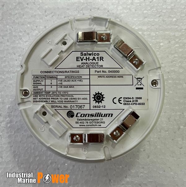
- Area: Optical chamber contamination and sensor foulingCheck: Inspect optical chamber visibility and sensor cleanliness; check for dust, debris, or discoloration on lens surfaces; verify LED light transmission through optical window; perform visual cleanliness assessment per EN54-7 maintenance procedures
- Area: Thermal sensor drift and heat detection accuracyCheck: Verify temperature sensing element operation via control panel diagnostics; check for slow response times; test thermal elements using heat gun at specified setpoints (54°C for A1R, 84°C for CS class); confirm rate-of-rise functionality within 0.8°C/min tolerance
- Area: Flame detector alignment and optical path obstructionCheck: Verify unobstructed line-of-sight between flame detector and protected area; check for window/lens blockage on UV and IR detectors; inspect for dirt accumulation on sapphire glass filters (AC-IR-3Fq); confirm 100-degree field of view clearance for UV detectors
- Area: Connector and wiring integrity in damp/marine environmentsCheck: Inspect all connections for corrosion or green patina; verify waterproof seals on IP67-rated detectors (HC100 A2-IP67, CS-MCP WP); check for loose terminal pins; test continuity of detector loops; ensure proper strain relief on cables in high-vibration areas
- Area: Address assignment and control panel communication failureCheck: Verify DIP-switch settings match commissioning documentation (NS-AOS N11111, NS-AOHS N11250, NS-AH detectors); perform address conflict scan via control panel; test loop communication at each detector node; confirm alarm signal generation and LED indication (red LED on alarm)
Typ-universelle Inspektionspunkte fuer Fire Detection Systems (verifiziert, 2026-06).
- Area: Optical chamber contamination and sensor foulingCheck: Inspect optical chamber visibility and sensor cleanliness; check for dust, debris, or discoloration on lens surfaces; verify LED light transmission through optical window; perform visual cleanliness assessment per EN54-7 maintenance procedures
- Area: Thermal sensor drift and heat detection accuracyCheck: Verify temperature sensing element operation via control panel diagnostics; check for slow response times; test thermal elements using heat gun at specified setpoints (54°C for A1R, 84°C for CS class); confirm rate-of-rise functionality within 0.8°C/min tolerance
- Area: Flame detector alignment and optical path obstructionCheck: Verify unobstructed line-of-sight between flame detector and protected area; check for window/lens blockage on UV and IR detectors; inspect for dirt accumulation on sapphire glass filters (AC-IR-3Fq); confirm 100-degree field of view clearance for UV detectors
- Area: Connector and wiring integrity in damp/marine environmentsCheck: Inspect all connections for corrosion or green patina; verify waterproof seals on IP67-rated detectors (HC100 A2-IP67, CS-MCP WP); check for loose terminal pins; test continuity of detector loops; ensure proper strain relief on cables in high-vibration areas
- Area: Address assignment and control panel communication failureCheck: Verify DIP-switch settings match commissioning documentation (NS-AOS N11111, NS-AOHS N11250, NS-AH detectors); perform address conflict scan via control panel; test loop communication at each detector node; confirm alarm signal generation and LED indication (red LED on alarm)
Typ-universelle Inspektionspunkte fuer Fire Detection Systems (verifiziert, 2026-06).
- Area: Optical chamber contamination and sensor foulingCheck: Inspect optical chamber visibility and sensor cleanliness; check for dust, debris, or discoloration on lens surfaces; verify LED light transmission through optical window; perform visual cleanliness assessment per EN54-7 maintenance procedures
- Area: Thermal sensor drift and heat detection accuracyCheck: Verify temperature sensing element operation via control panel diagnostics; check for slow response times; test thermal elements using heat gun at specified setpoints (54°C for A1R, 84°C for CS class); confirm rate-of-rise functionality within 0.8°C/min tolerance
- Area: Flame detector alignment and optical path obstructionCheck: Verify unobstructed line-of-sight between flame detector and protected area; check for window/lens blockage on UV and IR detectors; inspect for dirt accumulation on sapphire glass filters (AC-IR-3Fq); confirm 100-degree field of view clearance for UV detectors
- Area: Connector and wiring integrity in damp/marine environmentsCheck: Inspect all connections for corrosion or green patina; verify waterproof seals on IP67-rated detectors (HC100 A2-IP67, CS-MCP WP); check for loose terminal pins; test continuity of detector loops; ensure proper strain relief on cables in high-vibration areas
- Area: Address assignment and control panel communication failureCheck: Verify DIP-switch settings match commissioning documentation (NS-AOS N11111, NS-AOHS N11250, NS-AH detectors); perform address conflict scan via control panel; test loop communication at each detector node; confirm alarm signal generation and LED indication (red LED on alarm)
Typ-universelle Inspektionspunkte fuer Fire Detection Systems (verifiziert, 2026-06).
- Area: Optical chamber contamination and sensor foulingCheck: Inspect optical chamber visibility and sensor cleanliness; check for dust, debris, or discoloration on lens surfaces; verify LED light transmission through optical window; perform visual cleanliness assessment per EN54-7 maintenance procedures
- Area: Thermal sensor drift and heat detection accuracyCheck: Verify temperature sensing element operation via control panel diagnostics; check for slow response times; test thermal elements using heat gun at specified setpoints (54°C for A1R, 84°C for CS class); confirm rate-of-rise functionality within 0.8°C/min tolerance
- Area: Flame detector alignment and optical path obstructionCheck: Verify unobstructed line-of-sight between flame detector and protected area; check for window/lens blockage on UV and IR detectors; inspect for dirt accumulation on sapphire glass filters (AC-IR-3Fq); confirm 100-degree field of view clearance for UV detectors
- Area: Connector and wiring integrity in damp/marine environmentsCheck: Inspect all connections for corrosion or green patina; verify waterproof seals on IP67-rated detectors (HC100 A2-IP67, CS-MCP WP); check for loose terminal pins; test continuity of detector loops; ensure proper strain relief on cables in high-vibration areas
- Area: Address assignment and control panel communication failureCheck: Verify DIP-switch settings match commissioning documentation (NS-AOS N11111, NS-AOHS N11250, NS-AH detectors); perform address conflict scan via control panel; test loop communication at each detector node; confirm alarm signal generation and LED indication (red LED on alarm)
Typ-universelle Inspektionspunkte fuer Fire Detection Systems (verifiziert, 2026-06).
- Area: Optical chamber contamination and sensor foulingCheck: Inspect optical chamber visibility and sensor cleanliness; check for dust, debris, or discoloration on lens surfaces; verify LED light transmission through optical window; perform visual cleanliness assessment per EN54-7 maintenance procedures
- Area: Thermal sensor drift and heat detection accuracyCheck: Verify temperature sensing element operation via control panel diagnostics; check for slow response times; test thermal elements using heat gun at specified setpoints (54°C for A1R, 84°C for CS class); confirm rate-of-rise functionality within 0.8°C/min tolerance
- Area: Flame detector alignment and optical path obstructionCheck: Verify unobstructed line-of-sight between flame detector and protected area; check for window/lens blockage on UV and IR detectors; inspect for dirt accumulation on sapphire glass filters (AC-IR-3Fq); confirm 100-degree field of view clearance for UV detectors
- Area: Connector and wiring integrity in damp/marine environmentsCheck: Inspect all connections for corrosion or green patina; verify waterproof seals on IP67-rated detectors (HC100 A2-IP67, CS-MCP WP); check for loose terminal pins; test continuity of detector loops; ensure proper strain relief on cables in high-vibration areas
- Area: Address assignment and control panel communication failureCheck: Verify DIP-switch settings match commissioning documentation (NS-AOS N11111, NS-AOHS N11250, NS-AH detectors); perform address conflict scan via control panel; test loop communication at each detector node; confirm alarm signal generation and LED indication (red LED on alarm)
Typ-universelle Inspektionspunkte fuer Fire Detection Systems (verifiziert, 2026-06).
- Area: Optical chamber contamination and sensor foulingCheck: Inspect optical chamber visibility and sensor cleanliness; check for dust, debris, or discoloration on lens surfaces; verify LED light transmission through optical window; perform visual cleanliness assessment per EN54-7 maintenance procedures
- Area: Thermal sensor drift and heat detection accuracyCheck: Verify temperature sensing element operation via control panel diagnostics; check for slow response times; test thermal elements using heat gun at specified setpoints (54°C for A1R, 84°C for CS class); confirm rate-of-rise functionality within 0.8°C/min tolerance
- Area: Flame detector alignment and optical path obstructionCheck: Verify unobstructed line-of-sight between flame detector and protected area; check for window/lens blockage on UV and IR detectors; inspect for dirt accumulation on sapphire glass filters (AC-IR-3Fq); confirm 100-degree field of view clearance for UV detectors
- Area: Connector and wiring integrity in damp/marine environmentsCheck: Inspect all connections for corrosion or green patina; verify waterproof seals on IP67-rated detectors (HC100 A2-IP67, CS-MCP WP); check for loose terminal pins; test continuity of detector loops; ensure proper strain relief on cables in high-vibration areas
- Area: Address assignment and control panel communication failureCheck: Verify DIP-switch settings match commissioning documentation (NS-AOS N11111, NS-AOHS N11250, NS-AH detectors); perform address conflict scan via control panel; test loop communication at each detector node; confirm alarm signal generation and LED indication (red LED on alarm)
Typ-universelle Inspektionspunkte fuer Fire Detection Systems (verifiziert, 2026-06).
- Area: Optical chamber contamination and sensor foulingCheck: Inspect optical chamber visibility and sensor cleanliness; check for dust, debris, or discoloration on lens surfaces; verify LED light transmission through optical window; perform visual cleanliness assessment per EN54-7 maintenance procedures
- Area: Thermal sensor drift and heat detection accuracyCheck: Verify temperature sensing element operation via control panel diagnostics; check for slow response times; test thermal elements using heat gun at specified setpoints (54°C for A1R, 84°C for CS class); confirm rate-of-rise functionality within 0.8°C/min tolerance
- Area: Flame detector alignment and optical path obstructionCheck: Verify unobstructed line-of-sight between flame detector and protected area; check for window/lens blockage on UV and IR detectors; inspect for dirt accumulation on sapphire glass filters (AC-IR-3Fq); confirm 100-degree field of view clearance for UV detectors
- Area: Connector and wiring integrity in damp/marine environmentsCheck: Inspect all connections for corrosion or green patina; verify waterproof seals on IP67-rated detectors (HC100 A2-IP67, CS-MCP WP); check for loose terminal pins; test continuity of detector loops; ensure proper strain relief on cables in high-vibration areas
- Area: Address assignment and control panel communication failureCheck: Verify DIP-switch settings match commissioning documentation (NS-AOS N11111, NS-AOHS N11250, NS-AH detectors); perform address conflict scan via control panel; test loop communication at each detector node; confirm alarm signal generation and LED indication (red LED on alarm)
Typ-universelle Inspektionspunkte fuer Fire Detection Systems (verifiziert, 2026-06).
- Area: Optical chamber contamination and sensor foulingCheck: Inspect optical chamber visibility and sensor cleanliness; check for dust, debris, or discoloration on lens surfaces; verify LED light transmission through optical window; perform visual cleanliness assessment per EN54-7 maintenance procedures
- Area: Thermal sensor drift and heat detection accuracyCheck: Verify temperature sensing element operation via control panel diagnostics; check for slow response times; test thermal elements using heat gun at specified setpoints (54°C for A1R, 84°C for CS class); confirm rate-of-rise functionality within 0.8°C/min tolerance
- Area: Flame detector alignment and optical path obstructionCheck: Verify unobstructed line-of-sight between flame detector and protected area; check for window/lens blockage on UV and IR detectors; inspect for dirt accumulation on sapphire glass filters (AC-IR-3Fq); confirm 100-degree field of view clearance for UV detectors
- Area: Connector and wiring integrity in damp/marine environmentsCheck: Inspect all connections for corrosion or green patina; verify waterproof seals on IP67-rated detectors (HC100 A2-IP67, CS-MCP WP); check for loose terminal pins; test continuity of detector loops; ensure proper strain relief on cables in high-vibration areas
- Area: Address assignment and control panel communication failureCheck: Verify DIP-switch settings match commissioning documentation (NS-AOS N11111, NS-AOHS N11250, NS-AH detectors); perform address conflict scan via control panel; test loop communication at each detector node; confirm alarm signal generation and LED indication (red LED on alarm)
Typ-universelle Inspektionspunkte fuer Fire Detection Systems (verifiziert, 2026-06).
- Area: Optical chamber contamination and sensor foulingCheck: Inspect optical chamber visibility and sensor cleanliness; check for dust, debris, or discoloration on lens surfaces; verify LED light transmission through optical window; perform visual cleanliness assessment per EN54-7 maintenance procedures
- Area: Thermal sensor drift and heat detection accuracyCheck: Verify temperature sensing element operation via control panel diagnostics; check for slow response times; test thermal elements using heat gun at specified setpoints (54°C for A1R, 84°C for CS class); confirm rate-of-rise functionality within 0.8°C/min tolerance
- Area: Flame detector alignment and optical path obstructionCheck: Verify unobstructed line-of-sight between flame detector and protected area; check for window/lens blockage on UV and IR detectors; inspect for dirt accumulation on sapphire glass filters (AC-IR-3Fq); confirm 100-degree field of view clearance for UV detectors
- Area: Connector and wiring integrity in damp/marine environmentsCheck: Inspect all connections for corrosion or green patina; verify waterproof seals on IP67-rated detectors (HC100 A2-IP67, CS-MCP WP); check for loose terminal pins; test continuity of detector loops; ensure proper strain relief on cables in high-vibration areas
- Area: Address assignment and control panel communication failureCheck: Verify DIP-switch settings match commissioning documentation (NS-AOS N11111, NS-AOHS N11250, NS-AH detectors); perform address conflict scan via control panel; test loop communication at each detector node; confirm alarm signal generation and LED indication (red LED on alarm)
Typ-universelle Inspektionspunkte fuer Fire Detection Systems (verifiziert, 2026-06).
- Area: Optical chamber contamination and sensor foulingCheck: Inspect optical chamber visibility and sensor cleanliness; check for dust, debris, or discoloration on lens surfaces; verify LED light transmission through optical window; perform visual cleanliness assessment per EN54-7 maintenance procedures
- Area: Thermal sensor drift and heat detection accuracyCheck: Verify temperature sensing element operation via control panel diagnostics; check for slow response times; test thermal elements using heat gun at specified setpoints (54°C for A1R, 84°C for CS class); confirm rate-of-rise functionality within 0.8°C/min tolerance
- Area: Flame detector alignment and optical path obstructionCheck: Verify unobstructed line-of-sight between flame detector and protected area; check for window/lens blockage on UV and IR detectors; inspect for dirt accumulation on sapphire glass filters (AC-IR-3Fq); confirm 100-degree field of view clearance for UV detectors
- Area: Connector and wiring integrity in damp/marine environmentsCheck: Inspect all connections for corrosion or green patina; verify waterproof seals on IP67-rated detectors (HC100 A2-IP67, CS-MCP WP); check for loose terminal pins; test continuity of detector loops; ensure proper strain relief on cables in high-vibration areas
- Area: Address assignment and control panel communication failureCheck: Verify DIP-switch settings match commissioning documentation (NS-AOS N11111, NS-AOHS N11250, NS-AH detectors); perform address conflict scan via control panel; test loop communication at each detector node; confirm alarm signal generation and LED indication (red LED on alarm)
Typ-universelle Inspektionspunkte fuer Fire Detection Systems (verifiziert, 2026-06).
- Area: Optical chamber contamination and sensor foulingCheck: Inspect optical chamber visibility and sensor cleanliness; check for dust, debris, or discoloration on lens surfaces; verify LED light transmission through optical window; perform visual cleanliness assessment per EN54-7 maintenance procedures
- Area: Thermal sensor drift and heat detection accuracyCheck: Verify temperature sensing element operation via control panel diagnostics; check for slow response times; test thermal elements using heat gun at specified setpoints (54°C for A1R, 84°C for CS class); confirm rate-of-rise functionality within 0.8°C/min tolerance
- Area: Flame detector alignment and optical path obstructionCheck: Verify unobstructed line-of-sight between flame detector and protected area; check for window/lens blockage on UV and IR detectors; inspect for dirt accumulation on sapphire glass filters (AC-IR-3Fq); confirm 100-degree field of view clearance for UV detectors
- Area: Connector and wiring integrity in damp/marine environmentsCheck: Inspect all connections for corrosion or green patina; verify waterproof seals on IP67-rated detectors (HC100 A2-IP67, CS-MCP WP); check for loose terminal pins; test continuity of detector loops; ensure proper strain relief on cables in high-vibration areas
- Area: Address assignment and control panel communication failureCheck: Verify DIP-switch settings match commissioning documentation (NS-AOS N11111, NS-AOHS N11250, NS-AH detectors); perform address conflict scan via control panel; test loop communication at each detector node; confirm alarm signal generation and LED indication (red LED on alarm)
Typ-universelle Inspektionspunkte fuer Fire Detection Systems (verifiziert, 2026-06).
- Area: Optical chamber contamination and sensor foulingCheck: Inspect optical chamber visibility and sensor cleanliness; check for dust, debris, or discoloration on lens surfaces; verify LED light transmission through optical window; perform visual cleanliness assessment per EN54-7 maintenance procedures
- Area: Thermal sensor drift and heat detection accuracyCheck: Verify temperature sensing element operation via control panel diagnostics; check for slow response times; test thermal elements using heat gun at specified setpoints (54°C for A1R, 84°C for CS class); confirm rate-of-rise functionality within 0.8°C/min tolerance
- Area: Flame detector alignment and optical path obstructionCheck: Verify unobstructed line-of-sight between flame detector and protected area; check for window/lens blockage on UV and IR detectors; inspect for dirt accumulation on sapphire glass filters (AC-IR-3Fq); confirm 100-degree field of view clearance for UV detectors
- Area: Connector and wiring integrity in damp/marine environmentsCheck: Inspect all connections for corrosion or green patina; verify waterproof seals on IP67-rated detectors (HC100 A2-IP67, CS-MCP WP); check for loose terminal pins; test continuity of detector loops; ensure proper strain relief on cables in high-vibration areas
- Area: Address assignment and control panel communication failureCheck: Verify DIP-switch settings match commissioning documentation (NS-AOS N11111, NS-AOHS N11250, NS-AH detectors); perform address conflict scan via control panel; test loop communication at each detector node; confirm alarm signal generation and LED indication (red LED on alarm)
Typ-universelle Inspektionspunkte fuer Fire Detection Systems (verifiziert, 2026-06).
- Area: Optical chamber contamination and sensor foulingCheck: Inspect optical chamber visibility and sensor cleanliness; check for dust, debris, or discoloration on lens surfaces; verify LED light transmission through optical window; perform visual cleanliness assessment per EN54-7 maintenance procedures
- Area: Thermal sensor drift and heat detection accuracyCheck: Verify temperature sensing element operation via control panel diagnostics; check for slow response times; test thermal elements using heat gun at specified setpoints (54°C for A1R, 84°C for CS class); confirm rate-of-rise functionality within 0.8°C/min tolerance
- Area: Flame detector alignment and optical path obstructionCheck: Verify unobstructed line-of-sight between flame detector and protected area; check for window/lens blockage on UV and IR detectors; inspect for dirt accumulation on sapphire glass filters (AC-IR-3Fq); confirm 100-degree field of view clearance for UV detectors
- Area: Connector and wiring integrity in damp/marine environmentsCheck: Inspect all connections for corrosion or green patina; verify waterproof seals on IP67-rated detectors (HC100 A2-IP67, CS-MCP WP); check for loose terminal pins; test continuity of detector loops; ensure proper strain relief on cables in high-vibration areas
- Area: Address assignment and control panel communication failureCheck: Verify DIP-switch settings match commissioning documentation (NS-AOS N11111, NS-AOHS N11250, NS-AH detectors); perform address conflict scan via control panel; test loop communication at each detector node; confirm alarm signal generation and LED indication (red LED on alarm)
Typ-universelle Inspektionspunkte fuer Fire Detection Systems (verifiziert, 2026-06).
- Area: Optical chamber contamination and sensor foulingCheck: Inspect optical chamber visibility and sensor cleanliness; check for dust, debris, or discoloration on lens surfaces; verify LED light transmission through optical window; perform visual cleanliness assessment per EN54-7 maintenance procedures
- Area: Thermal sensor drift and heat detection accuracyCheck: Verify temperature sensing element operation via control panel diagnostics; check for slow response times; test thermal elements using heat gun at specified setpoints (54°C for A1R, 84°C for CS class); confirm rate-of-rise functionality within 0.8°C/min tolerance
- Area: Flame detector alignment and optical path obstructionCheck: Verify unobstructed line-of-sight between flame detector and protected area; check for window/lens blockage on UV and IR detectors; inspect for dirt accumulation on sapphire glass filters (AC-IR-3Fq); confirm 100-degree field of view clearance for UV detectors
- Area: Connector and wiring integrity in damp/marine environmentsCheck: Inspect all connections for corrosion or green patina; verify waterproof seals on IP67-rated detectors (HC100 A2-IP67, CS-MCP WP); check for loose terminal pins; test continuity of detector loops; ensure proper strain relief on cables in high-vibration areas
- Area: Address assignment and control panel communication failureCheck: Verify DIP-switch settings match commissioning documentation (NS-AOS N11111, NS-AOHS N11250, NS-AH detectors); perform address conflict scan via control panel; test loop communication at each detector node; confirm alarm signal generation and LED indication (red LED on alarm)
Typ-universelle Inspektionspunkte fuer Fire Detection Systems (verifiziert, 2026-06).
- Area: Optical chamber contamination and sensor foulingCheck: Inspect optical chamber visibility and sensor cleanliness; check for dust, debris, or discoloration on lens surfaces; verify LED light transmission through optical window; perform visual cleanliness assessment per EN54-7 maintenance procedures
- Area: Thermal sensor drift and heat detection accuracyCheck: Verify temperature sensing element operation via control panel diagnostics; check for slow response times; test thermal elements using heat gun at specified setpoints (54°C for A1R, 84°C for CS class); confirm rate-of-rise functionality within 0.8°C/min tolerance
- Area: Flame detector alignment and optical path obstructionCheck: Verify unobstructed line-of-sight between flame detector and protected area; check for window/lens blockage on UV and IR detectors; inspect for dirt accumulation on sapphire glass filters (AC-IR-3Fq); confirm 100-degree field of view clearance for UV detectors
- Area: Connector and wiring integrity in damp/marine environmentsCheck: Inspect all connections for corrosion or green patina; verify waterproof seals on IP67-rated detectors (HC100 A2-IP67, CS-MCP WP); check for loose terminal pins; test continuity of detector loops; ensure proper strain relief on cables in high-vibration areas
- Area: Address assignment and control panel communication failureCheck: Verify DIP-switch settings match commissioning documentation (NS-AOS N11111, NS-AOHS N11250, NS-AH detectors); perform address conflict scan via control panel; test loop communication at each detector node; confirm alarm signal generation and LED indication (red LED on alarm)
Typ-universelle Inspektionspunkte fuer Fire Detection Systems (verifiziert, 2026-06).
- Area: Optical chamber contamination and sensor foulingCheck: Inspect optical chamber visibility and sensor cleanliness; check for dust, debris, or discoloration on lens surfaces; verify LED light transmission through optical window; perform visual cleanliness assessment per EN54-7 maintenance procedures
- Area: Thermal sensor drift and heat detection accuracyCheck: Verify temperature sensing element operation via control panel diagnostics; check for slow response times; test thermal elements using heat gun at specified setpoints (54°C for A1R, 84°C for CS class); confirm rate-of-rise functionality within 0.8°C/min tolerance
- Area: Flame detector alignment and optical path obstructionCheck: Verify unobstructed line-of-sight between flame detector and protected area; check for window/lens blockage on UV and IR detectors; inspect for dirt accumulation on sapphire glass filters (AC-IR-3Fq); confirm 100-degree field of view clearance for UV detectors
- Area: Connector and wiring integrity in damp/marine environmentsCheck: Inspect all connections for corrosion or green patina; verify waterproof seals on IP67-rated detectors (HC100 A2-IP67, CS-MCP WP); check for loose terminal pins; test continuity of detector loops; ensure proper strain relief on cables in high-vibration areas
- Area: Address assignment and control panel communication failureCheck: Verify DIP-switch settings match commissioning documentation (NS-AOS N11111, NS-AOHS N11250, NS-AH detectors); perform address conflict scan via control panel; test loop communication at each detector node; confirm alarm signal generation and LED indication (red LED on alarm)
Typ-universelle Inspektionspunkte fuer Fire Detection Systems (verifiziert, 2026-06).
- Area: Optical chamber contamination and sensor foulingCheck: Inspect optical chamber visibility and sensor cleanliness; check for dust, debris, or discoloration on lens surfaces; verify LED light transmission through optical window; perform visual cleanliness assessment per EN54-7 maintenance procedures
- Area: Thermal sensor drift and heat detection accuracyCheck: Verify temperature sensing element operation via control panel diagnostics; check for slow response times; test thermal elements using heat gun at specified setpoints (54°C for A1R, 84°C for CS class); confirm rate-of-rise functionality within 0.8°C/min tolerance
- Area: Flame detector alignment and optical path obstructionCheck: Verify unobstructed line-of-sight between flame detector and protected area; check for window/lens blockage on UV and IR detectors; inspect for dirt accumulation on sapphire glass filters (AC-IR-3Fq); confirm 100-degree field of view clearance for UV detectors
- Area: Connector and wiring integrity in damp/marine environmentsCheck: Inspect all connections for corrosion or green patina; verify waterproof seals on IP67-rated detectors (HC100 A2-IP67, CS-MCP WP); check for loose terminal pins; test continuity of detector loops; ensure proper strain relief on cables in high-vibration areas
- Area: Address assignment and control panel communication failureCheck: Verify DIP-switch settings match commissioning documentation (NS-AOS N11111, NS-AOHS N11250, NS-AH detectors); perform address conflict scan via control panel; test loop communication at each detector node; confirm alarm signal generation and LED indication (red LED on alarm)
Typ-universelle Inspektionspunkte fuer Fire Detection Systems (verifiziert, 2026-06).
- Area: Optical chamber contamination and sensor foulingCheck: Inspect optical chamber visibility and sensor cleanliness; check for dust, debris, or discoloration on lens surfaces; verify LED light transmission through optical window; perform visual cleanliness assessment per EN54-7 maintenance procedures
- Area: Thermal sensor drift and heat detection accuracyCheck: Verify temperature sensing element operation via control panel diagnostics; check for slow response times; test thermal elements using heat gun at specified setpoints (54°C for A1R, 84°C for CS class); confirm rate-of-rise functionality within 0.8°C/min tolerance
- Area: Flame detector alignment and optical path obstructionCheck: Verify unobstructed line-of-sight between flame detector and protected area; check for window/lens blockage on UV and IR detectors; inspect for dirt accumulation on sapphire glass filters (AC-IR-3Fq); confirm 100-degree field of view clearance for UV detectors
- Area: Connector and wiring integrity in damp/marine environmentsCheck: Inspect all connections for corrosion or green patina; verify waterproof seals on IP67-rated detectors (HC100 A2-IP67, CS-MCP WP); check for loose terminal pins; test continuity of detector loops; ensure proper strain relief on cables in high-vibration areas
- Area: Address assignment and control panel communication failureCheck: Verify DIP-switch settings match commissioning documentation (NS-AOS N11111, NS-AOHS N11250, NS-AH detectors); perform address conflict scan via control panel; test loop communication at each detector node; confirm alarm signal generation and LED indication (red LED on alarm)
Typ-universelle Inspektionspunkte fuer Fire Detection Systems (verifiziert, 2026-06).
- Area: Optical chamber contamination and sensor foulingCheck: Inspect optical chamber visibility and sensor cleanliness; check for dust, debris, or discoloration on lens surfaces; verify LED light transmission through optical window; perform visual cleanliness assessment per EN54-7 maintenance procedures
- Area: Thermal sensor drift and heat detection accuracyCheck: Verify temperature sensing element operation via control panel diagnostics; check for slow response times; test thermal elements using heat gun at specified setpoints (54°C for A1R, 84°C for CS class); confirm rate-of-rise functionality within 0.8°C/min tolerance
- Area: Flame detector alignment and optical path obstructionCheck: Verify unobstructed line-of-sight between flame detector and protected area; check for window/lens blockage on UV and IR detectors; inspect for dirt accumulation on sapphire glass filters (AC-IR-3Fq); confirm 100-degree field of view clearance for UV detectors
- Area: Connector and wiring integrity in damp/marine environmentsCheck: Inspect all connections for corrosion or green patina; verify waterproof seals on IP67-rated detectors (HC100 A2-IP67, CS-MCP WP); check for loose terminal pins; test continuity of detector loops; ensure proper strain relief on cables in high-vibration areas
- Area: Address assignment and control panel communication failureCheck: Verify DIP-switch settings match commissioning documentation (NS-AOS N11111, NS-AOHS N11250, NS-AH detectors); perform address conflict scan via control panel; test loop communication at each detector node; confirm alarm signal generation and LED indication (red LED on alarm)
Typ-universelle Inspektionspunkte fuer Fire Detection Systems (verifiziert, 2026-06).
- Area: Optical chamber contamination and sensor foulingCheck: Inspect optical chamber visibility and sensor cleanliness; check for dust, debris, or discoloration on lens surfaces; verify LED light transmission through optical window; perform visual cleanliness assessment per EN54-7 maintenance procedures
- Area: Thermal sensor drift and heat detection accuracyCheck: Verify temperature sensing element operation via control panel diagnostics; check for slow response times; test thermal elements using heat gun at specified setpoints (54°C for A1R, 84°C for CS class); confirm rate-of-rise functionality within 0.8°C/min tolerance
- Area: Flame detector alignment and optical path obstructionCheck: Verify unobstructed line-of-sight between flame detector and protected area; check for window/lens blockage on UV and IR detectors; inspect for dirt accumulation on sapphire glass filters (AC-IR-3Fq); confirm 100-degree field of view clearance for UV detectors
- Area: Connector and wiring integrity in damp/marine environmentsCheck: Inspect all connections for corrosion or green patina; verify waterproof seals on IP67-rated detectors (HC100 A2-IP67, CS-MCP WP); check for loose terminal pins; test continuity of detector loops; ensure proper strain relief on cables in high-vibration areas
- Area: Address assignment and control panel communication failureCheck: Verify DIP-switch settings match commissioning documentation (NS-AOS N11111, NS-AOHS N11250, NS-AH detectors); perform address conflict scan via control panel; test loop communication at each detector node; confirm alarm signal generation and LED indication (red LED on alarm)
Typ-universelle Inspektionspunkte fuer Fire Detection Systems (verifiziert, 2026-06).
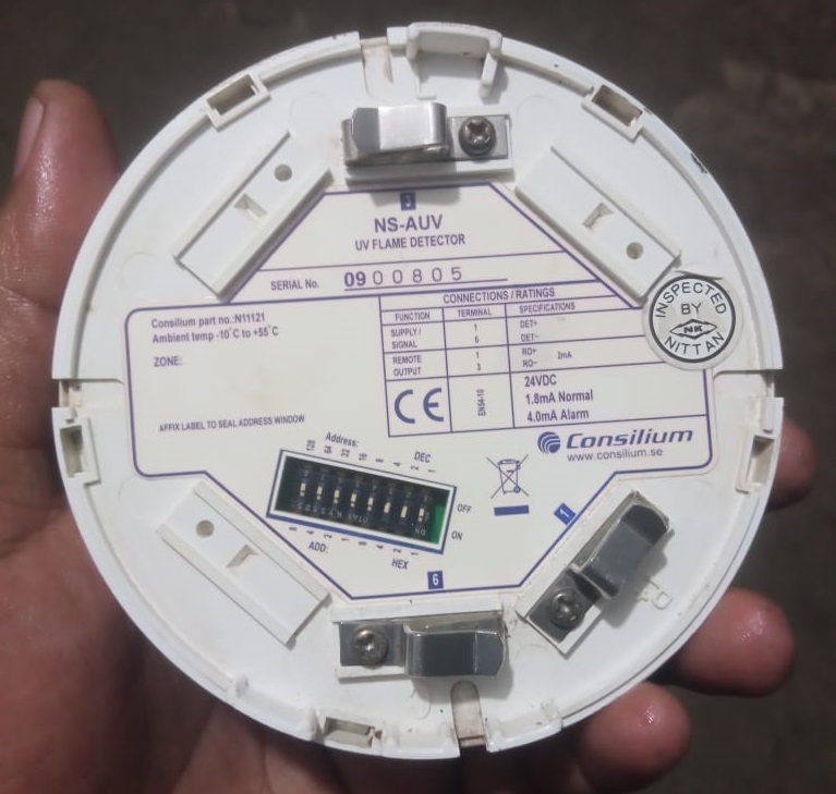
- Area: Optical chamber contamination and sensor foulingCheck: Inspect optical chamber visibility and sensor cleanliness; check for dust, debris, or discoloration on lens surfaces; verify LED light transmission through optical window; perform visual cleanliness assessment per EN54-7 maintenance procedures
- Area: Thermal sensor drift and heat detection accuracyCheck: Verify temperature sensing element operation via control panel diagnostics; check for slow response times; test thermal elements using heat gun at specified setpoints (54°C for A1R, 84°C for CS class); confirm rate-of-rise functionality within 0.8°C/min tolerance
- Area: Flame detector alignment and optical path obstructionCheck: Verify unobstructed line-of-sight between flame detector and protected area; check for window/lens blockage on UV and IR detectors; inspect for dirt accumulation on sapphire glass filters (AC-IR-3Fq); confirm 100-degree field of view clearance for UV detectors
- Area: Connector and wiring integrity in damp/marine environmentsCheck: Inspect all connections for corrosion or green patina; verify waterproof seals on IP67-rated detectors (HC100 A2-IP67, CS-MCP WP); check for loose terminal pins; test continuity of detector loops; ensure proper strain relief on cables in high-vibration areas
- Area: Address assignment and control panel communication failureCheck: Verify DIP-switch settings match commissioning documentation (NS-AOS N11111, NS-AOHS N11250, NS-AH detectors); perform address conflict scan via control panel; test loop communication at each detector node; confirm alarm signal generation and LED indication (red LED on alarm)
Typ-universelle Inspektionspunkte fuer Fire Detection Systems (verifiziert, 2026-06).
- Area: Optical chamber contamination and sensor foulingCheck: Inspect optical chamber visibility and sensor cleanliness; check for dust, debris, or discoloration on lens surfaces; verify LED light transmission through optical window; perform visual cleanliness assessment per EN54-7 maintenance procedures
- Area: Thermal sensor drift and heat detection accuracyCheck: Verify temperature sensing element operation via control panel diagnostics; check for slow response times; test thermal elements using heat gun at specified setpoints (54°C for A1R, 84°C for CS class); confirm rate-of-rise functionality within 0.8°C/min tolerance
- Area: Flame detector alignment and optical path obstructionCheck: Verify unobstructed line-of-sight between flame detector and protected area; check for window/lens blockage on UV and IR detectors; inspect for dirt accumulation on sapphire glass filters (AC-IR-3Fq); confirm 100-degree field of view clearance for UV detectors
- Area: Connector and wiring integrity in damp/marine environmentsCheck: Inspect all connections for corrosion or green patina; verify waterproof seals on IP67-rated detectors (HC100 A2-IP67, CS-MCP WP); check for loose terminal pins; test continuity of detector loops; ensure proper strain relief on cables in high-vibration areas
- Area: Address assignment and control panel communication failureCheck: Verify DIP-switch settings match commissioning documentation (NS-AOS N11111, NS-AOHS N11250, NS-AH detectors); perform address conflict scan via control panel; test loop communication at each detector node; confirm alarm signal generation and LED indication (red LED on alarm)
Typ-universelle Inspektionspunkte fuer Fire Detection Systems (verifiziert, 2026-06).
- Area: Optical chamber contamination and sensor foulingCheck: Inspect optical chamber visibility and sensor cleanliness; check for dust, debris, or discoloration on lens surfaces; verify LED light transmission through optical window; perform visual cleanliness assessment per EN54-7 maintenance procedures
- Area: Thermal sensor drift and heat detection accuracyCheck: Verify temperature sensing element operation via control panel diagnostics; check for slow response times; test thermal elements using heat gun at specified setpoints (54°C for A1R, 84°C for CS class); confirm rate-of-rise functionality within 0.8°C/min tolerance
- Area: Flame detector alignment and optical path obstructionCheck: Verify unobstructed line-of-sight between flame detector and protected area; check for window/lens blockage on UV and IR detectors; inspect for dirt accumulation on sapphire glass filters (AC-IR-3Fq); confirm 100-degree field of view clearance for UV detectors
- Area: Connector and wiring integrity in damp/marine environmentsCheck: Inspect all connections for corrosion or green patina; verify waterproof seals on IP67-rated detectors (HC100 A2-IP67, CS-MCP WP); check for loose terminal pins; test continuity of detector loops; ensure proper strain relief on cables in high-vibration areas
- Area: Address assignment and control panel communication failureCheck: Verify DIP-switch settings match commissioning documentation (NS-AOS N11111, NS-AOHS N11250, NS-AH detectors); perform address conflict scan via control panel; test loop communication at each detector node; confirm alarm signal generation and LED indication (red LED on alarm)
Typ-universelle Inspektionspunkte fuer Fire Detection Systems (verifiziert, 2026-06).
- Area: Optical chamber contamination and sensor foulingCheck: Inspect optical chamber visibility and sensor cleanliness; check for dust, debris, or discoloration on lens surfaces; verify LED light transmission through optical window; perform visual cleanliness assessment per EN54-7 maintenance procedures
- Area: Thermal sensor drift and heat detection accuracyCheck: Verify temperature sensing element operation via control panel diagnostics; check for slow response times; test thermal elements using heat gun at specified setpoints (54°C for A1R, 84°C for CS class); confirm rate-of-rise functionality within 0.8°C/min tolerance
- Area: Flame detector alignment and optical path obstructionCheck: Verify unobstructed line-of-sight between flame detector and protected area; check for window/lens blockage on UV and IR detectors; inspect for dirt accumulation on sapphire glass filters (AC-IR-3Fq); confirm 100-degree field of view clearance for UV detectors
- Area: Connector and wiring integrity in damp/marine environmentsCheck: Inspect all connections for corrosion or green patina; verify waterproof seals on IP67-rated detectors (HC100 A2-IP67, CS-MCP WP); check for loose terminal pins; test continuity of detector loops; ensure proper strain relief on cables in high-vibration areas
- Area: Address assignment and control panel communication failureCheck: Verify DIP-switch settings match commissioning documentation (NS-AOS N11111, NS-AOHS N11250, NS-AH detectors); perform address conflict scan via control panel; test loop communication at each detector node; confirm alarm signal generation and LED indication (red LED on alarm)
Typ-universelle Inspektionspunkte fuer Fire Detection Systems (verifiziert, 2026-06).
- Area: Optical chamber contamination and sensor foulingCheck: Inspect optical chamber visibility and sensor cleanliness; check for dust, debris, or discoloration on lens surfaces; verify LED light transmission through optical window; perform visual cleanliness assessment per EN54-7 maintenance procedures
- Area: Thermal sensor drift and heat detection accuracyCheck: Verify temperature sensing element operation via control panel diagnostics; check for slow response times; test thermal elements using heat gun at specified setpoints (54°C for A1R, 84°C for CS class); confirm rate-of-rise functionality within 0.8°C/min tolerance
- Area: Flame detector alignment and optical path obstructionCheck: Verify unobstructed line-of-sight between flame detector and protected area; check for window/lens blockage on UV and IR detectors; inspect for dirt accumulation on sapphire glass filters (AC-IR-3Fq); confirm 100-degree field of view clearance for UV detectors
- Area: Connector and wiring integrity in damp/marine environmentsCheck: Inspect all connections for corrosion or green patina; verify waterproof seals on IP67-rated detectors (HC100 A2-IP67, CS-MCP WP); check for loose terminal pins; test continuity of detector loops; ensure proper strain relief on cables in high-vibration areas
- Area: Address assignment and control panel communication failureCheck: Verify DIP-switch settings match commissioning documentation (NS-AOS N11111, NS-AOHS N11250, NS-AH detectors); perform address conflict scan via control panel; test loop communication at each detector node; confirm alarm signal generation and LED indication (red LED on alarm)
Typ-universelle Inspektionspunkte fuer Fire Detection Systems (verifiziert, 2026-06).
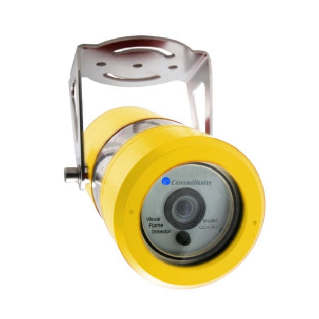
- Area: Optical chamber contamination and sensor foulingCheck: Inspect optical chamber visibility and sensor cleanliness; check for dust, debris, or discoloration on lens surfaces; verify LED light transmission through optical window; perform visual cleanliness assessment per EN54-7 maintenance procedures
- Area: Thermal sensor drift and heat detection accuracyCheck: Verify temperature sensing element operation via control panel diagnostics; check for slow response times; test thermal elements using heat gun at specified setpoints (54°C for A1R, 84°C for CS class); confirm rate-of-rise functionality within 0.8°C/min tolerance
- Area: Flame detector alignment and optical path obstructionCheck: Verify unobstructed line-of-sight between flame detector and protected area; check for window/lens blockage on UV and IR detectors; inspect for dirt accumulation on sapphire glass filters (AC-IR-3Fq); confirm 100-degree field of view clearance for UV detectors
- Area: Connector and wiring integrity in damp/marine environmentsCheck: Inspect all connections for corrosion or green patina; verify waterproof seals on IP67-rated detectors (HC100 A2-IP67, CS-MCP WP); check for loose terminal pins; test continuity of detector loops; ensure proper strain relief on cables in high-vibration areas
- Area: Address assignment and control panel communication failureCheck: Verify DIP-switch settings match commissioning documentation (NS-AOS N11111, NS-AOHS N11250, NS-AH detectors); perform address conflict scan via control panel; test loop communication at each detector node; confirm alarm signal generation and LED indication (red LED on alarm)
Typ-universelle Inspektionspunkte fuer Fire Detection Systems (verifiziert, 2026-06).
- Area: Optical chamber contamination and sensor foulingCheck: Inspect optical chamber visibility and sensor cleanliness; check for dust, debris, or discoloration on lens surfaces; verify LED light transmission through optical window; perform visual cleanliness assessment per EN54-7 maintenance procedures
- Area: Thermal sensor drift and heat detection accuracyCheck: Verify temperature sensing element operation via control panel diagnostics; check for slow response times; test thermal elements using heat gun at specified setpoints (54°C for A1R, 84°C for CS class); confirm rate-of-rise functionality within 0.8°C/min tolerance
- Area: Flame detector alignment and optical path obstructionCheck: Verify unobstructed line-of-sight between flame detector and protected area; check for window/lens blockage on UV and IR detectors; inspect for dirt accumulation on sapphire glass filters (AC-IR-3Fq); confirm 100-degree field of view clearance for UV detectors
- Area: Connector and wiring integrity in damp/marine environmentsCheck: Inspect all connections for corrosion or green patina; verify waterproof seals on IP67-rated detectors (HC100 A2-IP67, CS-MCP WP); check for loose terminal pins; test continuity of detector loops; ensure proper strain relief on cables in high-vibration areas
- Area: Address assignment and control panel communication failureCheck: Verify DIP-switch settings match commissioning documentation (NS-AOS N11111, NS-AOHS N11250, NS-AH detectors); perform address conflict scan via control panel; test loop communication at each detector node; confirm alarm signal generation and LED indication (red LED on alarm)
Typ-universelle Inspektionspunkte fuer Fire Detection Systems (verifiziert, 2026-06).
- Area: Optical chamber contamination and sensor foulingCheck: Inspect optical chamber visibility and sensor cleanliness; check for dust, debris, or discoloration on lens surfaces; verify LED light transmission through optical window; perform visual cleanliness assessment per EN54-7 maintenance procedures
- Area: Thermal sensor drift and heat detection accuracyCheck: Verify temperature sensing element operation via control panel diagnostics; check for slow response times; test thermal elements using heat gun at specified setpoints (54°C for A1R, 84°C for CS class); confirm rate-of-rise functionality within 0.8°C/min tolerance
- Area: Flame detector alignment and optical path obstructionCheck: Verify unobstructed line-of-sight between flame detector and protected area; check for window/lens blockage on UV and IR detectors; inspect for dirt accumulation on sapphire glass filters (AC-IR-3Fq); confirm 100-degree field of view clearance for UV detectors
- Area: Connector and wiring integrity in damp/marine environmentsCheck: Inspect all connections for corrosion or green patina; verify waterproof seals on IP67-rated detectors (HC100 A2-IP67, CS-MCP WP); check for loose terminal pins; test continuity of detector loops; ensure proper strain relief on cables in high-vibration areas
- Area: Address assignment and control panel communication failureCheck: Verify DIP-switch settings match commissioning documentation (NS-AOS N11111, NS-AOHS N11250, NS-AH detectors); perform address conflict scan via control panel; test loop communication at each detector node; confirm alarm signal generation and LED indication (red LED on alarm)
Typ-universelle Inspektionspunkte fuer Fire Detection Systems (verifiziert, 2026-06).
- Area: Optical chamber contamination and sensor foulingCheck: Inspect optical chamber visibility and sensor cleanliness; check for dust, debris, or discoloration on lens surfaces; verify LED light transmission through optical window; perform visual cleanliness assessment per EN54-7 maintenance procedures
- Area: Thermal sensor drift and heat detection accuracyCheck: Verify temperature sensing element operation via control panel diagnostics; check for slow response times; test thermal elements using heat gun at specified setpoints (54°C for A1R, 84°C for CS class); confirm rate-of-rise functionality within 0.8°C/min tolerance
- Area: Flame detector alignment and optical path obstructionCheck: Verify unobstructed line-of-sight between flame detector and protected area; check for window/lens blockage on UV and IR detectors; inspect for dirt accumulation on sapphire glass filters (AC-IR-3Fq); confirm 100-degree field of view clearance for UV detectors
- Area: Connector and wiring integrity in damp/marine environmentsCheck: Inspect all connections for corrosion or green patina; verify waterproof seals on IP67-rated detectors (HC100 A2-IP67, CS-MCP WP); check for loose terminal pins; test continuity of detector loops; ensure proper strain relief on cables in high-vibration areas
- Area: Address assignment and control panel communication failureCheck: Verify DIP-switch settings match commissioning documentation (NS-AOS N11111, NS-AOHS N11250, NS-AH detectors); perform address conflict scan via control panel; test loop communication at each detector node; confirm alarm signal generation and LED indication (red LED on alarm)
Typ-universelle Inspektionspunkte fuer Fire Detection Systems (verifiziert, 2026-06).
- Area: Optical chamber contamination and sensor foulingCheck: Inspect optical chamber visibility and sensor cleanliness; check for dust, debris, or discoloration on lens surfaces; verify LED light transmission through optical window; perform visual cleanliness assessment per EN54-7 maintenance procedures
- Area: Thermal sensor drift and heat detection accuracyCheck: Verify temperature sensing element operation via control panel diagnostics; check for slow response times; test thermal elements using heat gun at specified setpoints (54°C for A1R, 84°C for CS class); confirm rate-of-rise functionality within 0.8°C/min tolerance
- Area: Flame detector alignment and optical path obstructionCheck: Verify unobstructed line-of-sight between flame detector and protected area; check for window/lens blockage on UV and IR detectors; inspect for dirt accumulation on sapphire glass filters (AC-IR-3Fq); confirm 100-degree field of view clearance for UV detectors
- Area: Connector and wiring integrity in damp/marine environmentsCheck: Inspect all connections for corrosion or green patina; verify waterproof seals on IP67-rated detectors (HC100 A2-IP67, CS-MCP WP); check for loose terminal pins; test continuity of detector loops; ensure proper strain relief on cables in high-vibration areas
- Area: Address assignment and control panel communication failureCheck: Verify DIP-switch settings match commissioning documentation (NS-AOS N11111, NS-AOHS N11250, NS-AH detectors); perform address conflict scan via control panel; test loop communication at each detector node; confirm alarm signal generation and LED indication (red LED on alarm)
Typ-universelle Inspektionspunkte fuer Fire Detection Systems (verifiziert, 2026-06).
- Area: Optical chamber contamination and sensor foulingCheck: Inspect optical chamber visibility and sensor cleanliness; check for dust, debris, or discoloration on lens surfaces; verify LED light transmission through optical window; perform visual cleanliness assessment per EN54-7 maintenance procedures
- Area: Thermal sensor drift and heat detection accuracyCheck: Verify temperature sensing element operation via control panel diagnostics; check for slow response times; test thermal elements using heat gun at specified setpoints (54°C for A1R, 84°C for CS class); confirm rate-of-rise functionality within 0.8°C/min tolerance
- Area: Flame detector alignment and optical path obstructionCheck: Verify unobstructed line-of-sight between flame detector and protected area; check for window/lens blockage on UV and IR detectors; inspect for dirt accumulation on sapphire glass filters (AC-IR-3Fq); confirm 100-degree field of view clearance for UV detectors
- Area: Connector and wiring integrity in damp/marine environmentsCheck: Inspect all connections for corrosion or green patina; verify waterproof seals on IP67-rated detectors (HC100 A2-IP67, CS-MCP WP); check for loose terminal pins; test continuity of detector loops; ensure proper strain relief on cables in high-vibration areas
- Area: Address assignment and control panel communication failureCheck: Verify DIP-switch settings match commissioning documentation (NS-AOS N11111, NS-AOHS N11250, NS-AH detectors); perform address conflict scan via control panel; test loop communication at each detector node; confirm alarm signal generation and LED indication (red LED on alarm)
Typ-universelle Inspektionspunkte fuer Fire Detection Systems (verifiziert, 2026-06).
- Area: Optical chamber contamination and sensor foulingCheck: Inspect optical chamber visibility and sensor cleanliness; check for dust, debris, or discoloration on lens surfaces; verify LED light transmission through optical window; perform visual cleanliness assessment per EN54-7 maintenance procedures
- Area: Thermal sensor drift and heat detection accuracyCheck: Verify temperature sensing element operation via control panel diagnostics; check for slow response times; test thermal elements using heat gun at specified setpoints (54°C for A1R, 84°C for CS class); confirm rate-of-rise functionality within 0.8°C/min tolerance
- Area: Flame detector alignment and optical path obstructionCheck: Verify unobstructed line-of-sight between flame detector and protected area; check for window/lens blockage on UV and IR detectors; inspect for dirt accumulation on sapphire glass filters (AC-IR-3Fq); confirm 100-degree field of view clearance for UV detectors
- Area: Connector and wiring integrity in damp/marine environmentsCheck: Inspect all connections for corrosion or green patina; verify waterproof seals on IP67-rated detectors (HC100 A2-IP67, CS-MCP WP); check for loose terminal pins; test continuity of detector loops; ensure proper strain relief on cables in high-vibration areas
- Area: Address assignment and control panel communication failureCheck: Verify DIP-switch settings match commissioning documentation (NS-AOS N11111, NS-AOHS N11250, NS-AH detectors); perform address conflict scan via control panel; test loop communication at each detector node; confirm alarm signal generation and LED indication (red LED on alarm)
Typ-universelle Inspektionspunkte fuer Fire Detection Systems (verifiziert, 2026-06).
- Area: Optical chamber contamination and sensor foulingCheck: Inspect optical chamber visibility and sensor cleanliness; check for dust, debris, or discoloration on lens surfaces; verify LED light transmission through optical window; perform visual cleanliness assessment per EN54-7 maintenance procedures
- Area: Thermal sensor drift and heat detection accuracyCheck: Verify temperature sensing element operation via control panel diagnostics; check for slow response times; test thermal elements using heat gun at specified setpoints (54°C for A1R, 84°C for CS class); confirm rate-of-rise functionality within 0.8°C/min tolerance
- Area: Flame detector alignment and optical path obstructionCheck: Verify unobstructed line-of-sight between flame detector and protected area; check for window/lens blockage on UV and IR detectors; inspect for dirt accumulation on sapphire glass filters (AC-IR-3Fq); confirm 100-degree field of view clearance for UV detectors
- Area: Connector and wiring integrity in damp/marine environmentsCheck: Inspect all connections for corrosion or green patina; verify waterproof seals on IP67-rated detectors (HC100 A2-IP67, CS-MCP WP); check for loose terminal pins; test continuity of detector loops; ensure proper strain relief on cables in high-vibration areas
- Area: Address assignment and control panel communication failureCheck: Verify DIP-switch settings match commissioning documentation (NS-AOS N11111, NS-AOHS N11250, NS-AH detectors); perform address conflict scan via control panel; test loop communication at each detector node; confirm alarm signal generation and LED indication (red LED on alarm)
Typ-universelle Inspektionspunkte fuer Fire Detection Systems (verifiziert, 2026-06).
- Area: Optical chamber contamination and sensor foulingCheck: Inspect optical chamber visibility and sensor cleanliness; check for dust, debris, or discoloration on lens surfaces; verify LED light transmission through optical window; perform visual cleanliness assessment per EN54-7 maintenance procedures
- Area: Thermal sensor drift and heat detection accuracyCheck: Verify temperature sensing element operation via control panel diagnostics; check for slow response times; test thermal elements using heat gun at specified setpoints (54°C for A1R, 84°C for CS class); confirm rate-of-rise functionality within 0.8°C/min tolerance
- Area: Flame detector alignment and optical path obstructionCheck: Verify unobstructed line-of-sight between flame detector and protected area; check for window/lens blockage on UV and IR detectors; inspect for dirt accumulation on sapphire glass filters (AC-IR-3Fq); confirm 100-degree field of view clearance for UV detectors
- Area: Connector and wiring integrity in damp/marine environmentsCheck: Inspect all connections for corrosion or green patina; verify waterproof seals on IP67-rated detectors (HC100 A2-IP67, CS-MCP WP); check for loose terminal pins; test continuity of detector loops; ensure proper strain relief on cables in high-vibration areas
- Area: Address assignment and control panel communication failureCheck: Verify DIP-switch settings match commissioning documentation (NS-AOS N11111, NS-AOHS N11250, NS-AH detectors); perform address conflict scan via control panel; test loop communication at each detector node; confirm alarm signal generation and LED indication (red LED on alarm)
Typ-universelle Inspektionspunkte fuer Fire Detection Systems (verifiziert, 2026-06).
Minimax Marine
18 ✓ 18 verified- Area: Optical sensor contamination or window obscurationCheck: Visual inspection of detector lens and internal optical elements for dust, insect debris, corrosion, or condensation; perform monthly visual check and semi-annual smoke-entry functional test per NFPA 72
- Area: Sensitivity drift or sensor degradationCheck: Sensitivity testing of detector elements within 1 year after installation and every 2 years thereafter; for aspirating systems, verify suction pressure (>400 Pa) and air sample integrity
- Area: Physical damage or mechanical misalignmentCheck: Visual inspection for cracks, corrosion, impact damage; verify mounting security and alignment; check for loose connectors or cable damage; test mechanical self-testing indicators (for YMX5000 cyclic optics monitoring)
- Area: Electrical connection failure or signal lossCheck: Functional test of detector signal transmission to control panel; verify alarm and fault relay operations; test communication loop continuity; check battery status (for battery-powered units like Ei series), expected 10-year life
- Area: Age-related degradation and end-of-lifeCheck: Document installation date; replace heat detectors (WMX series) after 15 years maximum service life; replace aspirating smoke detectors (AMX series) per manufacturer recommendations typically 20-25 years; check for obsolescence of electronic components
Typ-universelle Inspektionspunkte fuer Fire Detection Systems (verifiziert, 2026-06).
- Area: Optical sensor contamination or window obscurationCheck: Visual inspection of detector lens and internal optical elements for dust, insect debris, corrosion, or condensation; perform monthly visual check and semi-annual smoke-entry functional test per NFPA 72
- Area: Sensitivity drift or sensor degradationCheck: Sensitivity testing of detector elements within 1 year after installation and every 2 years thereafter; for aspirating systems, verify suction pressure (>400 Pa) and air sample integrity
- Area: Physical damage or mechanical misalignmentCheck: Visual inspection for cracks, corrosion, impact damage; verify mounting security and alignment; check for loose connectors or cable damage; test mechanical self-testing indicators (for YMX5000 cyclic optics monitoring)
- Area: Electrical connection failure or signal lossCheck: Functional test of detector signal transmission to control panel; verify alarm and fault relay operations; test communication loop continuity; check battery status (for battery-powered units like Ei series), expected 10-year life
- Area: Age-related degradation and end-of-lifeCheck: Document installation date; replace heat detectors (WMX series) after 15 years maximum service life; replace aspirating smoke detectors (AMX series) per manufacturer recommendations typically 20-25 years; check for obsolescence of electronic components
Typ-universelle Inspektionspunkte fuer Fire Detection Systems (verifiziert, 2026-06).
- Area: Optical sensor contamination or window obscurationCheck: Visual inspection of detector lens and internal optical elements for dust, insect debris, corrosion, or condensation; perform monthly visual check and semi-annual smoke-entry functional test per NFPA 72
- Area: Sensitivity drift or sensor degradationCheck: Sensitivity testing of detector elements within 1 year after installation and every 2 years thereafter; for aspirating systems, verify suction pressure (>400 Pa) and air sample integrity
- Area: Physical damage or mechanical misalignmentCheck: Visual inspection for cracks, corrosion, impact damage; verify mounting security and alignment; check for loose connectors or cable damage; test mechanical self-testing indicators (for YMX5000 cyclic optics monitoring)
- Area: Electrical connection failure or signal lossCheck: Functional test of detector signal transmission to control panel; verify alarm and fault relay operations; test communication loop continuity; check battery status (for battery-powered units like Ei series), expected 10-year life
- Area: Age-related degradation and end-of-lifeCheck: Document installation date; replace heat detectors (WMX series) after 15 years maximum service life; replace aspirating smoke detectors (AMX series) per manufacturer recommendations typically 20-25 years; check for obsolescence of electronic components
Typ-universelle Inspektionspunkte fuer Fire Detection Systems (verifiziert, 2026-06).
- Area: Optical sensor contamination or window obscurationCheck: Visual inspection of detector lens and internal optical elements for dust, insect debris, corrosion, or condensation; perform monthly visual check and semi-annual smoke-entry functional test per NFPA 72
- Area: Sensitivity drift or sensor degradationCheck: Sensitivity testing of detector elements within 1 year after installation and every 2 years thereafter; for aspirating systems, verify suction pressure (>400 Pa) and air sample integrity
- Area: Physical damage or mechanical misalignmentCheck: Visual inspection for cracks, corrosion, impact damage; verify mounting security and alignment; check for loose connectors or cable damage; test mechanical self-testing indicators (for YMX5000 cyclic optics monitoring)
- Area: Electrical connection failure or signal lossCheck: Functional test of detector signal transmission to control panel; verify alarm and fault relay operations; test communication loop continuity; check battery status (for battery-powered units like Ei series), expected 10-year life
- Area: Age-related degradation and end-of-lifeCheck: Document installation date; replace heat detectors (WMX series) after 15 years maximum service life; replace aspirating smoke detectors (AMX series) per manufacturer recommendations typically 20-25 years; check for obsolescence of electronic components
Typ-universelle Inspektionspunkte fuer Fire Detection Systems (verifiziert, 2026-06).
- Area: Optical sensor contamination or window obscurationCheck: Visual inspection of detector lens and internal optical elements for dust, insect debris, corrosion, or condensation; perform monthly visual check and semi-annual smoke-entry functional test per NFPA 72
- Area: Sensitivity drift or sensor degradationCheck: Sensitivity testing of detector elements within 1 year after installation and every 2 years thereafter; for aspirating systems, verify suction pressure (>400 Pa) and air sample integrity
- Area: Physical damage or mechanical misalignmentCheck: Visual inspection for cracks, corrosion, impact damage; verify mounting security and alignment; check for loose connectors or cable damage; test mechanical self-testing indicators (for YMX5000 cyclic optics monitoring)
- Area: Electrical connection failure or signal lossCheck: Functional test of detector signal transmission to control panel; verify alarm and fault relay operations; test communication loop continuity; check battery status (for battery-powered units like Ei series), expected 10-year life
- Area: Age-related degradation and end-of-lifeCheck: Document installation date; replace heat detectors (WMX series) after 15 years maximum service life; replace aspirating smoke detectors (AMX series) per manufacturer recommendations typically 20-25 years; check for obsolescence of electronic components
Typ-universelle Inspektionspunkte fuer Fire Detection Systems (verifiziert, 2026-06).
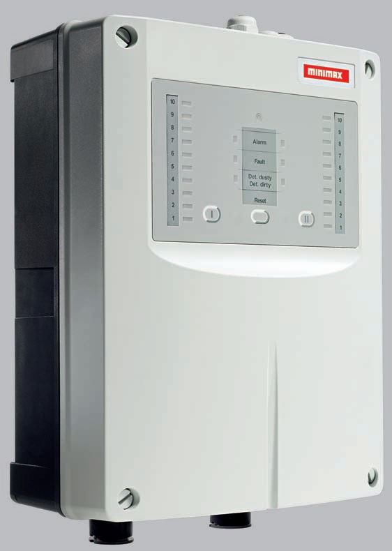
- Area: Optical sensor contamination or window obscurationCheck: Visual inspection of detector lens and internal optical elements for dust, insect debris, corrosion, or condensation; perform monthly visual check and semi-annual smoke-entry functional test per NFPA 72
- Area: Sensitivity drift or sensor degradationCheck: Sensitivity testing of detector elements within 1 year after installation and every 2 years thereafter; for aspirating systems, verify suction pressure (>400 Pa) and air sample integrity
- Area: Physical damage or mechanical misalignmentCheck: Visual inspection for cracks, corrosion, impact damage; verify mounting security and alignment; check for loose connectors or cable damage; test mechanical self-testing indicators (for YMX5000 cyclic optics monitoring)
- Area: Electrical connection failure or signal lossCheck: Functional test of detector signal transmission to control panel; verify alarm and fault relay operations; test communication loop continuity; check battery status (for battery-powered units like Ei series), expected 10-year life
- Area: Age-related degradation and end-of-lifeCheck: Document installation date; replace heat detectors (WMX series) after 15 years maximum service life; replace aspirating smoke detectors (AMX series) per manufacturer recommendations typically 20-25 years; check for obsolescence of electronic components
Typ-universelle Inspektionspunkte fuer Fire Detection Systems (verifiziert, 2026-06).
- Area: Optical sensor contamination or window obscurationCheck: Visual inspection of detector lens and internal optical elements for dust, insect debris, corrosion, or condensation; perform monthly visual check and semi-annual smoke-entry functional test per NFPA 72
- Area: Sensitivity drift or sensor degradationCheck: Sensitivity testing of detector elements within 1 year after installation and every 2 years thereafter; for aspirating systems, verify suction pressure (>400 Pa) and air sample integrity
- Area: Physical damage or mechanical misalignmentCheck: Visual inspection for cracks, corrosion, impact damage; verify mounting security and alignment; check for loose connectors or cable damage; test mechanical self-testing indicators (for YMX5000 cyclic optics monitoring)
- Area: Electrical connection failure or signal lossCheck: Functional test of detector signal transmission to control panel; verify alarm and fault relay operations; test communication loop continuity; check battery status (for battery-powered units like Ei series), expected 10-year life
- Area: Age-related degradation and end-of-lifeCheck: Document installation date; replace heat detectors (WMX series) after 15 years maximum service life; replace aspirating smoke detectors (AMX series) per manufacturer recommendations typically 20-25 years; check for obsolescence of electronic components
Typ-universelle Inspektionspunkte fuer Fire Detection Systems (verifiziert, 2026-06).
- Area: Optical sensor contamination or window obscurationCheck: Visual inspection of detector lens and internal optical elements for dust, insect debris, corrosion, or condensation; perform monthly visual check and semi-annual smoke-entry functional test per NFPA 72
- Area: Sensitivity drift or sensor degradationCheck: Sensitivity testing of detector elements within 1 year after installation and every 2 years thereafter; for aspirating systems, verify suction pressure (>400 Pa) and air sample integrity
- Area: Physical damage or mechanical misalignmentCheck: Visual inspection for cracks, corrosion, impact damage; verify mounting security and alignment; check for loose connectors or cable damage; test mechanical self-testing indicators (for YMX5000 cyclic optics monitoring)
- Area: Electrical connection failure or signal lossCheck: Functional test of detector signal transmission to control panel; verify alarm and fault relay operations; test communication loop continuity; check battery status (for battery-powered units like Ei series), expected 10-year life
- Area: Age-related degradation and end-of-lifeCheck: Document installation date; replace heat detectors (WMX series) after 15 years maximum service life; replace aspirating smoke detectors (AMX series) per manufacturer recommendations typically 20-25 years; check for obsolescence of electronic components
Typ-universelle Inspektionspunkte fuer Fire Detection Systems (verifiziert, 2026-06).
- Area: Optical sensor contamination or window obscurationCheck: Visual inspection of detector lens and internal optical elements for dust, insect debris, corrosion, or condensation; perform monthly visual check and semi-annual smoke-entry functional test per NFPA 72
- Area: Sensitivity drift or sensor degradationCheck: Sensitivity testing of detector elements within 1 year after installation and every 2 years thereafter; for aspirating systems, verify suction pressure (>400 Pa) and air sample integrity
- Area: Physical damage or mechanical misalignmentCheck: Visual inspection for cracks, corrosion, impact damage; verify mounting security and alignment; check for loose connectors or cable damage; test mechanical self-testing indicators (for YMX5000 cyclic optics monitoring)
- Area: Electrical connection failure or signal lossCheck: Functional test of detector signal transmission to control panel; verify alarm and fault relay operations; test communication loop continuity; check battery status (for battery-powered units like Ei series), expected 10-year life
- Area: Age-related degradation and end-of-lifeCheck: Document installation date; replace heat detectors (WMX series) after 15 years maximum service life; replace aspirating smoke detectors (AMX series) per manufacturer recommendations typically 20-25 years; check for obsolescence of electronic components
Typ-universelle Inspektionspunkte fuer Fire Detection Systems (verifiziert, 2026-06).
- Area: Optical sensor contamination or window obscurationCheck: Visual inspection of detector lens and internal optical elements for dust, insect debris, corrosion, or condensation; perform monthly visual check and semi-annual smoke-entry functional test per NFPA 72
- Area: Sensitivity drift or sensor degradationCheck: Sensitivity testing of detector elements within 1 year after installation and every 2 years thereafter; for aspirating systems, verify suction pressure (>400 Pa) and air sample integrity
- Area: Physical damage or mechanical misalignmentCheck: Visual inspection for cracks, corrosion, impact damage; verify mounting security and alignment; check for loose connectors or cable damage; test mechanical self-testing indicators (for YMX5000 cyclic optics monitoring)
- Area: Electrical connection failure or signal lossCheck: Functional test of detector signal transmission to control panel; verify alarm and fault relay operations; test communication loop continuity; check battery status (for battery-powered units like Ei series), expected 10-year life
- Area: Age-related degradation and end-of-lifeCheck: Document installation date; replace heat detectors (WMX series) after 15 years maximum service life; replace aspirating smoke detectors (AMX series) per manufacturer recommendations typically 20-25 years; check for obsolescence of electronic components
Typ-universelle Inspektionspunkte fuer Fire Detection Systems (verifiziert, 2026-06).
- Area: Optical sensor contamination or window obscurationCheck: Visual inspection of detector lens and internal optical elements for dust, insect debris, corrosion, or condensation; perform monthly visual check and semi-annual smoke-entry functional test per NFPA 72
- Area: Sensitivity drift or sensor degradationCheck: Sensitivity testing of detector elements within 1 year after installation and every 2 years thereafter; for aspirating systems, verify suction pressure (>400 Pa) and air sample integrity
- Area: Physical damage or mechanical misalignmentCheck: Visual inspection for cracks, corrosion, impact damage; verify mounting security and alignment; check for loose connectors or cable damage; test mechanical self-testing indicators (for YMX5000 cyclic optics monitoring)
- Area: Electrical connection failure or signal lossCheck: Functional test of detector signal transmission to control panel; verify alarm and fault relay operations; test communication loop continuity; check battery status (for battery-powered units like Ei series), expected 10-year life
- Area: Age-related degradation and end-of-lifeCheck: Document installation date; replace heat detectors (WMX series) after 15 years maximum service life; replace aspirating smoke detectors (AMX series) per manufacturer recommendations typically 20-25 years; check for obsolescence of electronic components
Typ-universelle Inspektionspunkte fuer Fire Detection Systems (verifiziert, 2026-06).
- Area: Optical sensor contamination or window obscurationCheck: Visual inspection of detector lens and internal optical elements for dust, insect debris, corrosion, or condensation; perform monthly visual check and semi-annual smoke-entry functional test per NFPA 72
- Area: Sensitivity drift or sensor degradationCheck: Sensitivity testing of detector elements within 1 year after installation and every 2 years thereafter; for aspirating systems, verify suction pressure (>400 Pa) and air sample integrity
- Area: Physical damage or mechanical misalignmentCheck: Visual inspection for cracks, corrosion, impact damage; verify mounting security and alignment; check for loose connectors or cable damage; test mechanical self-testing indicators (for YMX5000 cyclic optics monitoring)
- Area: Electrical connection failure or signal lossCheck: Functional test of detector signal transmission to control panel; verify alarm and fault relay operations; test communication loop continuity; check battery status (for battery-powered units like Ei series), expected 10-year life
- Area: Age-related degradation and end-of-lifeCheck: Document installation date; replace heat detectors (WMX series) after 15 years maximum service life; replace aspirating smoke detectors (AMX series) per manufacturer recommendations typically 20-25 years; check for obsolescence of electronic components
Typ-universelle Inspektionspunkte fuer Fire Detection Systems (verifiziert, 2026-06).
- Area: Optical sensor contamination or window obscurationCheck: Visual inspection of detector lens and internal optical elements for dust, insect debris, corrosion, or condensation; perform monthly visual check and semi-annual smoke-entry functional test per NFPA 72
- Area: Sensitivity drift or sensor degradationCheck: Sensitivity testing of detector elements within 1 year after installation and every 2 years thereafter; for aspirating systems, verify suction pressure (>400 Pa) and air sample integrity
- Area: Physical damage or mechanical misalignmentCheck: Visual inspection for cracks, corrosion, impact damage; verify mounting security and alignment; check for loose connectors or cable damage; test mechanical self-testing indicators (for YMX5000 cyclic optics monitoring)
- Area: Electrical connection failure or signal lossCheck: Functional test of detector signal transmission to control panel; verify alarm and fault relay operations; test communication loop continuity; check battery status (for battery-powered units like Ei series), expected 10-year life
- Area: Age-related degradation and end-of-lifeCheck: Document installation date; replace heat detectors (WMX series) after 15 years maximum service life; replace aspirating smoke detectors (AMX series) per manufacturer recommendations typically 20-25 years; check for obsolescence of electronic components
Typ-universelle Inspektionspunkte fuer Fire Detection Systems (verifiziert, 2026-06).
- Area: Optical sensor contamination or window obscurationCheck: Visual inspection of detector lens and internal optical elements for dust, insect debris, corrosion, or condensation; perform monthly visual check and semi-annual smoke-entry functional test per NFPA 72
- Area: Sensitivity drift or sensor degradationCheck: Sensitivity testing of detector elements within 1 year after installation and every 2 years thereafter; for aspirating systems, verify suction pressure (>400 Pa) and air sample integrity
- Area: Physical damage or mechanical misalignmentCheck: Visual inspection for cracks, corrosion, impact damage; verify mounting security and alignment; check for loose connectors or cable damage; test mechanical self-testing indicators (for YMX5000 cyclic optics monitoring)
- Area: Electrical connection failure or signal lossCheck: Functional test of detector signal transmission to control panel; verify alarm and fault relay operations; test communication loop continuity; check battery status (for battery-powered units like Ei series), expected 10-year life
- Area: Age-related degradation and end-of-lifeCheck: Document installation date; replace heat detectors (WMX series) after 15 years maximum service life; replace aspirating smoke detectors (AMX series) per manufacturer recommendations typically 20-25 years; check for obsolescence of electronic components
Typ-universelle Inspektionspunkte fuer Fire Detection Systems (verifiziert, 2026-06).
- Area: Optical sensor contamination or window obscurationCheck: Visual inspection of detector lens and internal optical elements for dust, insect debris, corrosion, or condensation; perform monthly visual check and semi-annual smoke-entry functional test per NFPA 72
- Area: Sensitivity drift or sensor degradationCheck: Sensitivity testing of detector elements within 1 year after installation and every 2 years thereafter; for aspirating systems, verify suction pressure (>400 Pa) and air sample integrity
- Area: Physical damage or mechanical misalignmentCheck: Visual inspection for cracks, corrosion, impact damage; verify mounting security and alignment; check for loose connectors or cable damage; test mechanical self-testing indicators (for YMX5000 cyclic optics monitoring)
- Area: Electrical connection failure or signal lossCheck: Functional test of detector signal transmission to control panel; verify alarm and fault relay operations; test communication loop continuity; check battery status (for battery-powered units like Ei series), expected 10-year life
- Area: Age-related degradation and end-of-lifeCheck: Document installation date; replace heat detectors (WMX series) after 15 years maximum service life; replace aspirating smoke detectors (AMX series) per manufacturer recommendations typically 20-25 years; check for obsolescence of electronic components
Typ-universelle Inspektionspunkte fuer Fire Detection Systems (verifiziert, 2026-06).
- Area: Optical sensor contamination or window obscurationCheck: Visual inspection of detector lens and internal optical elements for dust, insect debris, corrosion, or condensation; perform monthly visual check and semi-annual smoke-entry functional test per NFPA 72
- Area: Sensitivity drift or sensor degradationCheck: Sensitivity testing of detector elements within 1 year after installation and every 2 years thereafter; for aspirating systems, verify suction pressure (>400 Pa) and air sample integrity
- Area: Physical damage or mechanical misalignmentCheck: Visual inspection for cracks, corrosion, impact damage; verify mounting security and alignment; check for loose connectors or cable damage; test mechanical self-testing indicators (for YMX5000 cyclic optics monitoring)
- Area: Electrical connection failure or signal lossCheck: Functional test of detector signal transmission to control panel; verify alarm and fault relay operations; test communication loop continuity; check battery status (for battery-powered units like Ei series), expected 10-year life
- Area: Age-related degradation and end-of-lifeCheck: Document installation date; replace heat detectors (WMX series) after 15 years maximum service life; replace aspirating smoke detectors (AMX series) per manufacturer recommendations typically 20-25 years; check for obsolescence of electronic components
Typ-universelle Inspektionspunkte fuer Fire Detection Systems (verifiziert, 2026-06).
- Area: Optical sensor contamination or window obscurationCheck: Visual inspection of detector lens and internal optical elements for dust, insect debris, corrosion, or condensation; perform monthly visual check and semi-annual smoke-entry functional test per NFPA 72
- Area: Sensitivity drift or sensor degradationCheck: Sensitivity testing of detector elements within 1 year after installation and every 2 years thereafter; for aspirating systems, verify suction pressure (>400 Pa) and air sample integrity
- Area: Physical damage or mechanical misalignmentCheck: Visual inspection for cracks, corrosion, impact damage; verify mounting security and alignment; check for loose connectors or cable damage; test mechanical self-testing indicators (for YMX5000 cyclic optics monitoring)
- Area: Electrical connection failure or signal lossCheck: Functional test of detector signal transmission to control panel; verify alarm and fault relay operations; test communication loop continuity; check battery status (for battery-powered units like Ei series), expected 10-year life
- Area: Age-related degradation and end-of-lifeCheck: Document installation date; replace heat detectors (WMX series) after 15 years maximum service life; replace aspirating smoke detectors (AMX series) per manufacturer recommendations typically 20-25 years; check for obsolescence of electronic components
Typ-universelle Inspektionspunkte fuer Fire Detection Systems (verifiziert, 2026-06).
- Area: Optical sensor contamination or window obscurationCheck: Visual inspection of detector lens and internal optical elements for dust, insect debris, corrosion, or condensation; perform monthly visual check and semi-annual smoke-entry functional test per NFPA 72
- Area: Sensitivity drift or sensor degradationCheck: Sensitivity testing of detector elements within 1 year after installation and every 2 years thereafter; for aspirating systems, verify suction pressure (>400 Pa) and air sample integrity
- Area: Physical damage or mechanical misalignmentCheck: Visual inspection for cracks, corrosion, impact damage; verify mounting security and alignment; check for loose connectors or cable damage; test mechanical self-testing indicators (for YMX5000 cyclic optics monitoring)
- Area: Electrical connection failure or signal lossCheck: Functional test of detector signal transmission to control panel; verify alarm and fault relay operations; test communication loop continuity; check battery status (for battery-powered units like Ei series), expected 10-year life
- Area: Age-related degradation and end-of-lifeCheck: Document installation date; replace heat detectors (WMX series) after 15 years maximum service life; replace aspirating smoke detectors (AMX series) per manufacturer recommendations typically 20-25 years; check for obsolescence of electronic components
Typ-universelle Inspektionspunkte fuer Fire Detection Systems (verifiziert, 2026-06).
Dräger
15 ✓ 15 verified- Area: Optical window contamination (dust, oil, moisture, soot)Check: Visually inspect optical window for debris; perform automatic built-in test (BIT) for window contamination; clean with lint-free cloth and isopropyl alcohol if contamination detected; even minor contamination can reduce sensitivity by up to 50% per NFPA 72
- Area: Sensor sensitivity drift or degradationCheck: Perform sensitivity testing using manufacturer-approved test methods (e.g., Dräger FS-5000 flame simulator for Flame detectors); test within 1 year of installation and every 2 years thereafter; sensors outside rated range must be cleaned, recalibrated, or replaced
- Area: Mechanical obstructions blocking field of viewCheck: Verify unobstructed field of view per specifications; check for dust, condensation, or physical objects blocking detector line of sight; confirm mounting position and alignment; use visual technology (Flame 5000) or bore-sight tools to verify clear optical path
- Area: Electrical and communication failures (loss of signal, intermittent faults)Check: Verify 18-32 VDC power supply and correct polarity; test HART/Modbus communication if equipped; check 4-20 mA signal output (normal ~4 mA, warning ~16 mA, alarm 20 mA); perform monthly functional tests; verify LED indicator status (green=normal, yellow=fault, red=radiation detected)
- Area: Environmental stress (temperature extremes, harsh conditions, salt spray)Check: Confirm detector rated for actual operating environment (-60°C to +85°C range for Flame 5000; ATEX/IECEx for hazardous areas); inspect for corrosion of stainless steel or aluminum housing; in offshore/dusty environments increase cleaning frequency to quarterly or monthly vs. annual minimum
Typ-universelle Inspektionspunkte fuer Fire Detection Systems (verifiziert, 2026-06).
- Area: Optical window contamination (dust, oil, moisture, soot)Check: Visually inspect optical window for debris; perform automatic built-in test (BIT) for window contamination; clean with lint-free cloth and isopropyl alcohol if contamination detected; even minor contamination can reduce sensitivity by up to 50% per NFPA 72
- Area: Sensor sensitivity drift or degradationCheck: Perform sensitivity testing using manufacturer-approved test methods (e.g., Dräger FS-5000 flame simulator for Flame detectors); test within 1 year of installation and every 2 years thereafter; sensors outside rated range must be cleaned, recalibrated, or replaced
- Area: Mechanical obstructions blocking field of viewCheck: Verify unobstructed field of view per specifications; check for dust, condensation, or physical objects blocking detector line of sight; confirm mounting position and alignment; use visual technology (Flame 5000) or bore-sight tools to verify clear optical path
- Area: Electrical and communication failures (loss of signal, intermittent faults)Check: Verify 18-32 VDC power supply and correct polarity; test HART/Modbus communication if equipped; check 4-20 mA signal output (normal ~4 mA, warning ~16 mA, alarm 20 mA); perform monthly functional tests; verify LED indicator status (green=normal, yellow=fault, red=radiation detected)
- Area: Environmental stress (temperature extremes, harsh conditions, salt spray)Check: Confirm detector rated for actual operating environment (-60°C to +85°C range for Flame 5000; ATEX/IECEx for hazardous areas); inspect for corrosion of stainless steel or aluminum housing; in offshore/dusty environments increase cleaning frequency to quarterly or monthly vs. annual minimum
Typ-universelle Inspektionspunkte fuer Fire Detection Systems (verifiziert, 2026-06).
- Area: Optical window contamination (dust, oil, moisture, soot)Check: Visually inspect optical window for debris; perform automatic built-in test (BIT) for window contamination; clean with lint-free cloth and isopropyl alcohol if contamination detected; even minor contamination can reduce sensitivity by up to 50% per NFPA 72
- Area: Sensor sensitivity drift or degradationCheck: Perform sensitivity testing using manufacturer-approved test methods (e.g., Dräger FS-5000 flame simulator for Flame detectors); test within 1 year of installation and every 2 years thereafter; sensors outside rated range must be cleaned, recalibrated, or replaced
- Area: Mechanical obstructions blocking field of viewCheck: Verify unobstructed field of view per specifications; check for dust, condensation, or physical objects blocking detector line of sight; confirm mounting position and alignment; use visual technology (Flame 5000) or bore-sight tools to verify clear optical path
- Area: Electrical and communication failures (loss of signal, intermittent faults)Check: Verify 18-32 VDC power supply and correct polarity; test HART/Modbus communication if equipped; check 4-20 mA signal output (normal ~4 mA, warning ~16 mA, alarm 20 mA); perform monthly functional tests; verify LED indicator status (green=normal, yellow=fault, red=radiation detected)
- Area: Environmental stress (temperature extremes, harsh conditions, salt spray)Check: Confirm detector rated for actual operating environment (-60°C to +85°C range for Flame 5000; ATEX/IECEx for hazardous areas); inspect for corrosion of stainless steel or aluminum housing; in offshore/dusty environments increase cleaning frequency to quarterly or monthly vs. annual minimum
Typ-universelle Inspektionspunkte fuer Fire Detection Systems (verifiziert, 2026-06).
- Area: Optical window contamination (dust, oil, moisture, soot)Check: Visually inspect optical window for debris; perform automatic built-in test (BIT) for window contamination; clean with lint-free cloth and isopropyl alcohol if contamination detected; even minor contamination can reduce sensitivity by up to 50% per NFPA 72
- Area: Sensor sensitivity drift or degradationCheck: Perform sensitivity testing using manufacturer-approved test methods (e.g., Dräger FS-5000 flame simulator for Flame detectors); test within 1 year of installation and every 2 years thereafter; sensors outside rated range must be cleaned, recalibrated, or replaced
- Area: Mechanical obstructions blocking field of viewCheck: Verify unobstructed field of view per specifications; check for dust, condensation, or physical objects blocking detector line of sight; confirm mounting position and alignment; use visual technology (Flame 5000) or bore-sight tools to verify clear optical path
- Area: Electrical and communication failures (loss of signal, intermittent faults)Check: Verify 18-32 VDC power supply and correct polarity; test HART/Modbus communication if equipped; check 4-20 mA signal output (normal ~4 mA, warning ~16 mA, alarm 20 mA); perform monthly functional tests; verify LED indicator status (green=normal, yellow=fault, red=radiation detected)
- Area: Environmental stress (temperature extremes, harsh conditions, salt spray)Check: Confirm detector rated for actual operating environment (-60°C to +85°C range for Flame 5000; ATEX/IECEx for hazardous areas); inspect for corrosion of stainless steel or aluminum housing; in offshore/dusty environments increase cleaning frequency to quarterly or monthly vs. annual minimum
Typ-universelle Inspektionspunkte fuer Fire Detection Systems (verifiziert, 2026-06).
- Area: Optical window contamination (dust, oil, moisture, soot)Check: Visually inspect optical window for debris; perform automatic built-in test (BIT) for window contamination; clean with lint-free cloth and isopropyl alcohol if contamination detected; even minor contamination can reduce sensitivity by up to 50% per NFPA 72
- Area: Sensor sensitivity drift or degradationCheck: Perform sensitivity testing using manufacturer-approved test methods (e.g., Dräger FS-5000 flame simulator for Flame detectors); test within 1 year of installation and every 2 years thereafter; sensors outside rated range must be cleaned, recalibrated, or replaced
- Area: Mechanical obstructions blocking field of viewCheck: Verify unobstructed field of view per specifications; check for dust, condensation, or physical objects blocking detector line of sight; confirm mounting position and alignment; use visual technology (Flame 5000) or bore-sight tools to verify clear optical path
- Area: Electrical and communication failures (loss of signal, intermittent faults)Check: Verify 18-32 VDC power supply and correct polarity; test HART/Modbus communication if equipped; check 4-20 mA signal output (normal ~4 mA, warning ~16 mA, alarm 20 mA); perform monthly functional tests; verify LED indicator status (green=normal, yellow=fault, red=radiation detected)
- Area: Environmental stress (temperature extremes, harsh conditions, salt spray)Check: Confirm detector rated for actual operating environment (-60°C to +85°C range for Flame 5000; ATEX/IECEx for hazardous areas); inspect for corrosion of stainless steel or aluminum housing; in offshore/dusty environments increase cleaning frequency to quarterly or monthly vs. annual minimum
Typ-universelle Inspektionspunkte fuer Fire Detection Systems (verifiziert, 2026-06).
- Area: Optical window contamination (dust, oil, moisture, soot)Check: Visually inspect optical window for debris; perform automatic built-in test (BIT) for window contamination; clean with lint-free cloth and isopropyl alcohol if contamination detected; even minor contamination can reduce sensitivity by up to 50% per NFPA 72
- Area: Sensor sensitivity drift or degradationCheck: Perform sensitivity testing using manufacturer-approved test methods (e.g., Dräger FS-5000 flame simulator for Flame detectors); test within 1 year of installation and every 2 years thereafter; sensors outside rated range must be cleaned, recalibrated, or replaced
- Area: Mechanical obstructions blocking field of viewCheck: Verify unobstructed field of view per specifications; check for dust, condensation, or physical objects blocking detector line of sight; confirm mounting position and alignment; use visual technology (Flame 5000) or bore-sight tools to verify clear optical path
- Area: Electrical and communication failures (loss of signal, intermittent faults)Check: Verify 18-32 VDC power supply and correct polarity; test HART/Modbus communication if equipped; check 4-20 mA signal output (normal ~4 mA, warning ~16 mA, alarm 20 mA); perform monthly functional tests; verify LED indicator status (green=normal, yellow=fault, red=radiation detected)
- Area: Environmental stress (temperature extremes, harsh conditions, salt spray)Check: Confirm detector rated for actual operating environment (-60°C to +85°C range for Flame 5000; ATEX/IECEx for hazardous areas); inspect for corrosion of stainless steel or aluminum housing; in offshore/dusty environments increase cleaning frequency to quarterly or monthly vs. annual minimum
Typ-universelle Inspektionspunkte fuer Fire Detection Systems (verifiziert, 2026-06).
- Area: Optical window contamination (dust, oil, moisture, soot)Check: Visually inspect optical window for debris; perform automatic built-in test (BIT) for window contamination; clean with lint-free cloth and isopropyl alcohol if contamination detected; even minor contamination can reduce sensitivity by up to 50% per NFPA 72
- Area: Sensor sensitivity drift or degradationCheck: Perform sensitivity testing using manufacturer-approved test methods (e.g., Dräger FS-5000 flame simulator for Flame detectors); test within 1 year of installation and every 2 years thereafter; sensors outside rated range must be cleaned, recalibrated, or replaced
- Area: Mechanical obstructions blocking field of viewCheck: Verify unobstructed field of view per specifications; check for dust, condensation, or physical objects blocking detector line of sight; confirm mounting position and alignment; use visual technology (Flame 5000) or bore-sight tools to verify clear optical path
- Area: Electrical and communication failures (loss of signal, intermittent faults)Check: Verify 18-32 VDC power supply and correct polarity; test HART/Modbus communication if equipped; check 4-20 mA signal output (normal ~4 mA, warning ~16 mA, alarm 20 mA); perform monthly functional tests; verify LED indicator status (green=normal, yellow=fault, red=radiation detected)
- Area: Environmental stress (temperature extremes, harsh conditions, salt spray)Check: Confirm detector rated for actual operating environment (-60°C to +85°C range for Flame 5000; ATEX/IECEx for hazardous areas); inspect for corrosion of stainless steel or aluminum housing; in offshore/dusty environments increase cleaning frequency to quarterly or monthly vs. annual minimum
Typ-universelle Inspektionspunkte fuer Fire Detection Systems (verifiziert, 2026-06).
- Area: Optical window contamination (dust, oil, moisture, soot)Check: Visually inspect optical window for debris; perform automatic built-in test (BIT) for window contamination; clean with lint-free cloth and isopropyl alcohol if contamination detected; even minor contamination can reduce sensitivity by up to 50% per NFPA 72
- Area: Sensor sensitivity drift or degradationCheck: Perform sensitivity testing using manufacturer-approved test methods (e.g., Dräger FS-5000 flame simulator for Flame detectors); test within 1 year of installation and every 2 years thereafter; sensors outside rated range must be cleaned, recalibrated, or replaced
- Area: Mechanical obstructions blocking field of viewCheck: Verify unobstructed field of view per specifications; check for dust, condensation, or physical objects blocking detector line of sight; confirm mounting position and alignment; use visual technology (Flame 5000) or bore-sight tools to verify clear optical path
- Area: Electrical and communication failures (loss of signal, intermittent faults)Check: Verify 18-32 VDC power supply and correct polarity; test HART/Modbus communication if equipped; check 4-20 mA signal output (normal ~4 mA, warning ~16 mA, alarm 20 mA); perform monthly functional tests; verify LED indicator status (green=normal, yellow=fault, red=radiation detected)
- Area: Environmental stress (temperature extremes, harsh conditions, salt spray)Check: Confirm detector rated for actual operating environment (-60°C to +85°C range for Flame 5000; ATEX/IECEx for hazardous areas); inspect for corrosion of stainless steel or aluminum housing; in offshore/dusty environments increase cleaning frequency to quarterly or monthly vs. annual minimum
Typ-universelle Inspektionspunkte fuer Fire Detection Systems (verifiziert, 2026-06).
- Area: Optical window contamination (dust, oil, moisture, soot)Check: Visually inspect optical window for debris; perform automatic built-in test (BIT) for window contamination; clean with lint-free cloth and isopropyl alcohol if contamination detected; even minor contamination can reduce sensitivity by up to 50% per NFPA 72
- Area: Sensor sensitivity drift or degradationCheck: Perform sensitivity testing using manufacturer-approved test methods (e.g., Dräger FS-5000 flame simulator for Flame detectors); test within 1 year of installation and every 2 years thereafter; sensors outside rated range must be cleaned, recalibrated, or replaced
- Area: Mechanical obstructions blocking field of viewCheck: Verify unobstructed field of view per specifications; check for dust, condensation, or physical objects blocking detector line of sight; confirm mounting position and alignment; use visual technology (Flame 5000) or bore-sight tools to verify clear optical path
- Area: Electrical and communication failures (loss of signal, intermittent faults)Check: Verify 18-32 VDC power supply and correct polarity; test HART/Modbus communication if equipped; check 4-20 mA signal output (normal ~4 mA, warning ~16 mA, alarm 20 mA); perform monthly functional tests; verify LED indicator status (green=normal, yellow=fault, red=radiation detected)
- Area: Environmental stress (temperature extremes, harsh conditions, salt spray)Check: Confirm detector rated for actual operating environment (-60°C to +85°C range for Flame 5000; ATEX/IECEx for hazardous areas); inspect for corrosion of stainless steel or aluminum housing; in offshore/dusty environments increase cleaning frequency to quarterly or monthly vs. annual minimum
Typ-universelle Inspektionspunkte fuer Fire Detection Systems (verifiziert, 2026-06).
- Area: Optical window contamination (dust, oil, moisture, soot)Check: Visually inspect optical window for debris; perform automatic built-in test (BIT) for window contamination; clean with lint-free cloth and isopropyl alcohol if contamination detected; even minor contamination can reduce sensitivity by up to 50% per NFPA 72
- Area: Sensor sensitivity drift or degradationCheck: Perform sensitivity testing using manufacturer-approved test methods (e.g., Dräger FS-5000 flame simulator for Flame detectors); test within 1 year of installation and every 2 years thereafter; sensors outside rated range must be cleaned, recalibrated, or replaced
- Area: Mechanical obstructions blocking field of viewCheck: Verify unobstructed field of view per specifications; check for dust, condensation, or physical objects blocking detector line of sight; confirm mounting position and alignment; use visual technology (Flame 5000) or bore-sight tools to verify clear optical path
- Area: Electrical and communication failures (loss of signal, intermittent faults)Check: Verify 18-32 VDC power supply and correct polarity; test HART/Modbus communication if equipped; check 4-20 mA signal output (normal ~4 mA, warning ~16 mA, alarm 20 mA); perform monthly functional tests; verify LED indicator status (green=normal, yellow=fault, red=radiation detected)
- Area: Environmental stress (temperature extremes, harsh conditions, salt spray)Check: Confirm detector rated for actual operating environment (-60°C to +85°C range for Flame 5000; ATEX/IECEx for hazardous areas); inspect for corrosion of stainless steel or aluminum housing; in offshore/dusty environments increase cleaning frequency to quarterly or monthly vs. annual minimum
Typ-universelle Inspektionspunkte fuer Fire Detection Systems (verifiziert, 2026-06).
- Area: Optical window contamination (dust, oil, moisture, soot)Check: Visually inspect optical window for debris; perform automatic built-in test (BIT) for window contamination; clean with lint-free cloth and isopropyl alcohol if contamination detected; even minor contamination can reduce sensitivity by up to 50% per NFPA 72
- Area: Sensor sensitivity drift or degradationCheck: Perform sensitivity testing using manufacturer-approved test methods (e.g., Dräger FS-5000 flame simulator for Flame detectors); test within 1 year of installation and every 2 years thereafter; sensors outside rated range must be cleaned, recalibrated, or replaced
- Area: Mechanical obstructions blocking field of viewCheck: Verify unobstructed field of view per specifications; check for dust, condensation, or physical objects blocking detector line of sight; confirm mounting position and alignment; use visual technology (Flame 5000) or bore-sight tools to verify clear optical path
- Area: Electrical and communication failures (loss of signal, intermittent faults)Check: Verify 18-32 VDC power supply and correct polarity; test HART/Modbus communication if equipped; check 4-20 mA signal output (normal ~4 mA, warning ~16 mA, alarm 20 mA); perform monthly functional tests; verify LED indicator status (green=normal, yellow=fault, red=radiation detected)
- Area: Environmental stress (temperature extremes, harsh conditions, salt spray)Check: Confirm detector rated for actual operating environment (-60°C to +85°C range for Flame 5000; ATEX/IECEx for hazardous areas); inspect for corrosion of stainless steel or aluminum housing; in offshore/dusty environments increase cleaning frequency to quarterly or monthly vs. annual minimum
Typ-universelle Inspektionspunkte fuer Fire Detection Systems (verifiziert, 2026-06).
- Area: Optical window contamination (dust, oil, moisture, soot)Check: Visually inspect optical window for debris; perform automatic built-in test (BIT) for window contamination; clean with lint-free cloth and isopropyl alcohol if contamination detected; even minor contamination can reduce sensitivity by up to 50% per NFPA 72
- Area: Sensor sensitivity drift or degradationCheck: Perform sensitivity testing using manufacturer-approved test methods (e.g., Dräger FS-5000 flame simulator for Flame detectors); test within 1 year of installation and every 2 years thereafter; sensors outside rated range must be cleaned, recalibrated, or replaced
- Area: Mechanical obstructions blocking field of viewCheck: Verify unobstructed field of view per specifications; check for dust, condensation, or physical objects blocking detector line of sight; confirm mounting position and alignment; use visual technology (Flame 5000) or bore-sight tools to verify clear optical path
- Area: Electrical and communication failures (loss of signal, intermittent faults)Check: Verify 18-32 VDC power supply and correct polarity; test HART/Modbus communication if equipped; check 4-20 mA signal output (normal ~4 mA, warning ~16 mA, alarm 20 mA); perform monthly functional tests; verify LED indicator status (green=normal, yellow=fault, red=radiation detected)
- Area: Environmental stress (temperature extremes, harsh conditions, salt spray)Check: Confirm detector rated for actual operating environment (-60°C to +85°C range for Flame 5000; ATEX/IECEx for hazardous areas); inspect for corrosion of stainless steel or aluminum housing; in offshore/dusty environments increase cleaning frequency to quarterly or monthly vs. annual minimum
Typ-universelle Inspektionspunkte fuer Fire Detection Systems (verifiziert, 2026-06).
- Area: Optical window contamination (dust, oil, moisture, soot)Check: Visually inspect optical window for debris; perform automatic built-in test (BIT) for window contamination; clean with lint-free cloth and isopropyl alcohol if contamination detected; even minor contamination can reduce sensitivity by up to 50% per NFPA 72
- Area: Sensor sensitivity drift or degradationCheck: Perform sensitivity testing using manufacturer-approved test methods (e.g., Dräger FS-5000 flame simulator for Flame detectors); test within 1 year of installation and every 2 years thereafter; sensors outside rated range must be cleaned, recalibrated, or replaced
- Area: Mechanical obstructions blocking field of viewCheck: Verify unobstructed field of view per specifications; check for dust, condensation, or physical objects blocking detector line of sight; confirm mounting position and alignment; use visual technology (Flame 5000) or bore-sight tools to verify clear optical path
- Area: Electrical and communication failures (loss of signal, intermittent faults)Check: Verify 18-32 VDC power supply and correct polarity; test HART/Modbus communication if equipped; check 4-20 mA signal output (normal ~4 mA, warning ~16 mA, alarm 20 mA); perform monthly functional tests; verify LED indicator status (green=normal, yellow=fault, red=radiation detected)
- Area: Environmental stress (temperature extremes, harsh conditions, salt spray)Check: Confirm detector rated for actual operating environment (-60°C to +85°C range for Flame 5000; ATEX/IECEx for hazardous areas); inspect for corrosion of stainless steel or aluminum housing; in offshore/dusty environments increase cleaning frequency to quarterly or monthly vs. annual minimum
Typ-universelle Inspektionspunkte fuer Fire Detection Systems (verifiziert, 2026-06).
- Area: Optical window contamination (dust, oil, moisture, soot)Check: Visually inspect optical window for debris; perform automatic built-in test (BIT) for window contamination; clean with lint-free cloth and isopropyl alcohol if contamination detected; even minor contamination can reduce sensitivity by up to 50% per NFPA 72
- Area: Sensor sensitivity drift or degradationCheck: Perform sensitivity testing using manufacturer-approved test methods (e.g., Dräger FS-5000 flame simulator for Flame detectors); test within 1 year of installation and every 2 years thereafter; sensors outside rated range must be cleaned, recalibrated, or replaced
- Area: Mechanical obstructions blocking field of viewCheck: Verify unobstructed field of view per specifications; check for dust, condensation, or physical objects blocking detector line of sight; confirm mounting position and alignment; use visual technology (Flame 5000) or bore-sight tools to verify clear optical path
- Area: Electrical and communication failures (loss of signal, intermittent faults)Check: Verify 18-32 VDC power supply and correct polarity; test HART/Modbus communication if equipped; check 4-20 mA signal output (normal ~4 mA, warning ~16 mA, alarm 20 mA); perform monthly functional tests; verify LED indicator status (green=normal, yellow=fault, red=radiation detected)
- Area: Environmental stress (temperature extremes, harsh conditions, salt spray)Check: Confirm detector rated for actual operating environment (-60°C to +85°C range for Flame 5000; ATEX/IECEx for hazardous areas); inspect for corrosion of stainless steel or aluminum housing; in offshore/dusty environments increase cleaning frequency to quarterly or monthly vs. annual minimum
Typ-universelle Inspektionspunkte fuer Fire Detection Systems (verifiziert, 2026-06).
- Area: Optical window contamination (dust, oil, moisture, soot)Check: Visually inspect optical window for debris; perform automatic built-in test (BIT) for window contamination; clean with lint-free cloth and isopropyl alcohol if contamination detected; even minor contamination can reduce sensitivity by up to 50% per NFPA 72
- Area: Sensor sensitivity drift or degradationCheck: Perform sensitivity testing using manufacturer-approved test methods (e.g., Dräger FS-5000 flame simulator for Flame detectors); test within 1 year of installation and every 2 years thereafter; sensors outside rated range must be cleaned, recalibrated, or replaced
- Area: Mechanical obstructions blocking field of viewCheck: Verify unobstructed field of view per specifications; check for dust, condensation, or physical objects blocking detector line of sight; confirm mounting position and alignment; use visual technology (Flame 5000) or bore-sight tools to verify clear optical path
- Area: Electrical and communication failures (loss of signal, intermittent faults)Check: Verify 18-32 VDC power supply and correct polarity; test HART/Modbus communication if equipped; check 4-20 mA signal output (normal ~4 mA, warning ~16 mA, alarm 20 mA); perform monthly functional tests; verify LED indicator status (green=normal, yellow=fault, red=radiation detected)
- Area: Environmental stress (temperature extremes, harsh conditions, salt spray)Check: Confirm detector rated for actual operating environment (-60°C to +85°C range for Flame 5000; ATEX/IECEx for hazardous areas); inspect for corrosion of stainless steel or aluminum housing; in offshore/dusty environments increase cleaning frequency to quarterly or monthly vs. annual minimum
Typ-universelle Inspektionspunkte fuer Fire Detection Systems (verifiziert, 2026-06).
Apollo Fire Detectors
15- Detector contamination or ageing, typically indicated by false alarms, reduced sensitivity or detector fault indication
- Loop wiring open/short circuit from cable or terminal damage, typically indicated by zone/loop fault alarms and loss of multiple devices
- Power-supply or backup-battery failure, typically indicated by panel power alarms or loss of standby capability
- Addressable module or panel electronics fault, typically indicated by missing devices, communication errors or unstable indications
- Incorrect detector placement/obstruction or damaged sensing path, typically indicated by slow or unreliable detection during testing
- Dust, salt, oil or contamination at the sensing element causes false alarms, reduced sensitivity or failed tests
- Water ingress or condensation causes intermittent alarms or detector failure
- Loop wiring, base or address faults cause missing-device or communication alarms
- Paint, covers or physical obstruction prevents the detector from sensing the protected space correctly
- Ageing electronics or sensor deterioration causes repeated nuisance alarms or failure during test
- Detector contamination or sensor aging caused by dust, grease, moisture or long service, resulting in false alarms, slow response or fault indication
- Loop or cable fault caused by damaged wiring, loose terminals or earth leakage, resulting in missing devices, intermittent faults or a loop alarm
- Addressing or configuration error caused by replacement or software changes, resulting in incorrect device identification or unavailable zones
- Power-supply or backup-battery deterioration caused by charger faults, aged batteries or wiring problems, resulting in power alarms or reduced standby capability
- Panel, relay or communication failure caused by electronics faults, resulting in missing alarms, failed outputs or loss of connection to other safety systems
- Detector contamination or sensor aging caused by dust, grease, moisture or long service, resulting in false alarms, slow response or fault indication
- Loop or cable fault caused by damaged wiring, loose terminals or earth leakage, resulting in missing devices, intermittent faults or a loop alarm
- Addressing or configuration error caused by replacement or software changes, resulting in incorrect device identification or unavailable zones
- Power-supply or backup-battery deterioration caused by charger faults, aged batteries or wiring problems, resulting in power alarms or reduced standby capability
- Panel, relay or communication failure caused by electronics faults, resulting in missing alarms, failed outputs or loss of connection to other safety systems
- Detector or sensing-element contamination caused by dust, grease, moisture or aging, resulting in false alarms, slow response or fault indication
- Loop or cable fault caused by damaged wiring, loose terminals or earth leakage, resulting in missing devices or intermittent system faults
- Addressing or configuration error caused by replacement or software changes, resulting in incorrect device identification or unavailable zones
- Power-supply or backup-battery deterioration caused by charger faults or aged batteries, resulting in power alarms or reduced standby capability
- Panel, relay or communication failure caused by electronics faults, resulting in missing alarms, failed outputs or loss of connection to other safety systems
- Detector contamination or ageing, typically indicated by false alarms, reduced sensitivity or detector fault indication
- Loop wiring open/short circuit from cable or terminal damage, typically indicated by zone/loop fault alarms and loss of multiple devices
- Power-supply or backup-battery failure, typically indicated by panel power alarms or loss of standby capability
- Addressable module or panel electronics fault, typically indicated by missing devices, communication errors or unstable indications
- Incorrect detector placement/obstruction or damaged sensing path, typically indicated by slow or unreliable detection during testing
- Dust, salt, oil or contamination at the sensing element causes false alarms, reduced sensitivity or failed tests
- Water ingress or condensation causes intermittent alarms or detector failure
- Loop wiring, base or address faults cause missing-device or communication alarms
- Paint, covers or physical obstruction prevents the detector from sensing the protected space correctly
- Ageing electronics or sensor deterioration causes repeated nuisance alarms or failure during test
- Detector contamination or sensor aging caused by dust, grease, moisture or long service, resulting in false alarms, slow response or fault indication
- Loop or cable fault caused by damaged wiring, loose terminals or earth leakage, resulting in missing devices, intermittent faults or a loop alarm
- Addressing or configuration error caused by replacement or software changes, resulting in incorrect device identification or unavailable zones
- Power-supply or backup-battery deterioration caused by charger faults, aged batteries or wiring problems, resulting in power alarms or reduced standby capability
- Panel, relay or communication failure caused by electronics faults, resulting in missing alarms, failed outputs or loss of connection to other safety systems
- Detector contamination or sensor aging can cause nuisance alarms or reduced sensitivity, noticed as repeated false alarms or failed tests
- Open or short circuits in loops and zones can isolate devices, shown by fault indications at the panel
- Power-supply or battery faults can reduce system availability, seen as charger, supply or standby-power alarms
- Addressing or configuration errors can identify the wrong device or zone, noticed during functional testing
- Moisture, corrosion or loose terminals can create intermittent faults, seen as unstable loop status or recurring device communication alarms
- Detector contamination or sensor aging can cause nuisance alarms or reduced sensitivity, noticed as repeated false alarms or failed tests
- Open or short circuits in loops and zones can isolate devices, shown by fault indications at the panel
- Power-supply or battery faults can reduce system availability, seen as charger, supply or standby-power alarms
- Addressing or configuration errors can identify the wrong device or zone, noticed during functional testing
- Moisture, corrosion or loose terminals can create intermittent faults, seen as unstable loop status or recurring device communication alarms
- Detector contamination or sensor aging can cause nuisance alarms or reduced sensitivity, noticed as repeated false alarms or failed tests
- Open or short circuits in loops and zones can isolate devices, shown by fault indications at the panel
- Power-supply or battery faults can reduce system availability, seen as charger, supply or standby-power alarms
- Addressing or configuration errors can identify the wrong device or zone, noticed during functional testing
- Moisture, corrosion or loose terminals can create intermittent faults, seen as unstable loop status or recurring device communication alarms
- Detector contamination or sensor aging can cause nuisance alarms or reduced sensitivity, noticed as repeated false alarms or failed tests
- Open or short circuits in loops and zones can isolate devices, shown by fault indications at the panel
- Power-supply or battery faults can reduce system availability, seen as charger, supply or standby-power alarms
- Addressing or configuration errors can identify the wrong device or zone, noticed during functional testing
- Moisture, corrosion or loose terminals can create intermittent faults, seen as unstable loop status or recurring device communication alarms
- Detector contamination or sensor aging can cause nuisance alarms or reduced sensitivity, noticed as repeated false alarms or failed tests
- Open or short circuits in loops and zones can isolate devices, shown by fault indications at the panel
- Power-supply or battery faults can reduce system availability, seen as charger, supply or standby-power alarms
- Addressing or configuration errors can identify the wrong device or zone, noticed during functional testing
- Moisture, corrosion or loose terminals can create intermittent faults, seen as unstable loop status or recurring device communication alarms
- Detector contamination or sensor aging can cause nuisance alarms or reduced sensitivity, noticed as repeated false alarms or failed tests
- Open or short circuits in loops and zones can isolate devices, shown by fault indications at the panel
- Power-supply or battery faults can reduce system availability, seen as charger, supply or standby-power alarms
- Addressing or configuration errors can identify the wrong device or zone, noticed during functional testing
- Moisture, corrosion or loose terminals can create intermittent faults, seen as unstable loop status or recurring device communication alarms
- Detector contamination or sensor aging can cause nuisance alarms or reduced sensitivity, noticed as repeated false alarms or failed tests
- Open or short circuits in loops and zones can isolate devices, shown by fault indications at the panel
- Power-supply or battery faults can reduce system availability, seen as charger, supply or standby-power alarms
- Addressing or configuration errors can identify the wrong device or zone, noticed during functional testing
- Moisture, corrosion or loose terminals can create intermittent faults, seen as unstable loop status or recurring device communication alarms
Siemens Fire Safety
12- Detector contamination or ageing, typically indicated by false alarms, reduced sensitivity or detector fault indication
- Loop wiring open/short circuit from cable or terminal damage, typically indicated by zone/loop fault alarms and loss of multiple devices
- Power-supply or backup-battery failure, typically indicated by panel power alarms or loss of standby capability
- Addressable module or panel electronics fault, typically indicated by missing devices, communication errors or unstable indications
- Incorrect detector placement/obstruction or damaged sensing path, typically indicated by slow or unreliable detection during testing
- Detector contamination or ageing, typically indicated by false alarms, reduced sensitivity or detector fault indication
- Loop wiring open/short circuit from cable or terminal damage, typically indicated by zone/loop fault alarms and loss of multiple devices
- Power-supply or backup-battery failure, typically indicated by panel power alarms or loss of standby capability
- Addressable module or panel electronics fault, typically indicated by missing devices, communication errors or unstable indications
- Incorrect detector placement/obstruction or damaged sensing path, typically indicated by slow or unreliable detection during testing
- Detector or sensing-element contamination, poisoning or ageing can cause false alarms, slow response or failed functional tests
- Battery, power-supply or control-circuit faults caused by ageing, loose wiring or blown protection can lead to trouble alarms or unavailable safety functions
- Cylinder pressure loss, leakage or damaged valves where stored media is used can leave the equipment outside ready condition and may be found during inspection or weighing checks
- Blocked, corroded or mechanically damaged nozzles, piping, hoses or masks can restrict discharge or breathing flow and show as poor functional test results
- Incorrect isolation, expired service status or disturbed release interlocks after maintenance can prevent normal arming and create panel faults or failed readiness checks
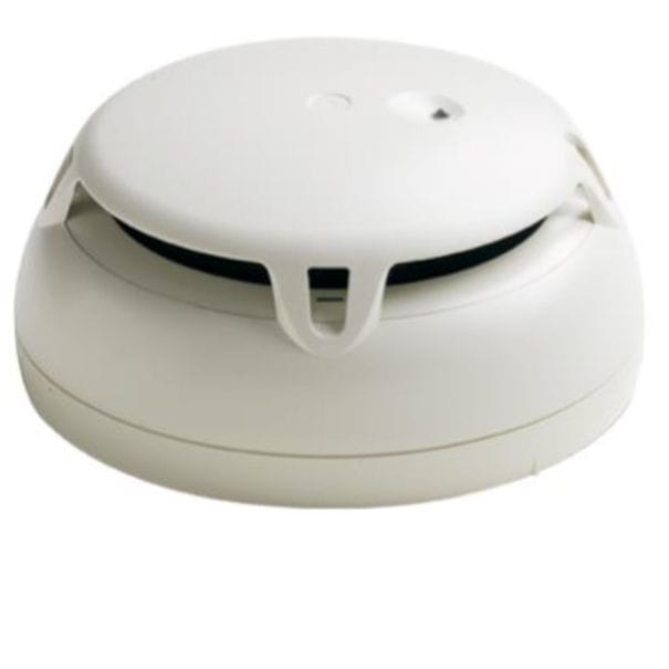
- Detector or sensing-element contamination, poisoning or ageing can cause false alarms, slow response or failed functional tests
- Battery, power-supply or control-circuit faults caused by ageing, loose wiring or blown protection can lead to trouble alarms or unavailable safety functions
- Cylinder pressure loss, leakage or damaged valves where stored media is used can leave the equipment outside ready condition and may be found during inspection or weighing checks
- Blocked, corroded or mechanically damaged nozzles, piping, hoses or masks can restrict discharge or breathing flow and show as poor functional test results
- Incorrect isolation, expired service status or disturbed release interlocks after maintenance can prevent normal arming and create panel faults or failed readiness checks
- Detector or sensing-element contamination, poisoning or ageing can cause false alarms, slow response or failed functional tests
- Battery, power-supply or control-circuit faults caused by ageing, loose wiring or blown protection can lead to trouble alarms or unavailable safety functions
- Cylinder pressure loss, leakage or damaged valves where stored media is used can leave the equipment outside ready condition and may be found during inspection or weighing checks
- Blocked, corroded or mechanically damaged nozzles, piping, hoses or masks can restrict discharge or breathing flow and show as poor functional test results
- Incorrect isolation, expired service status or disturbed release interlocks after maintenance can prevent normal arming and create panel faults or failed readiness checks
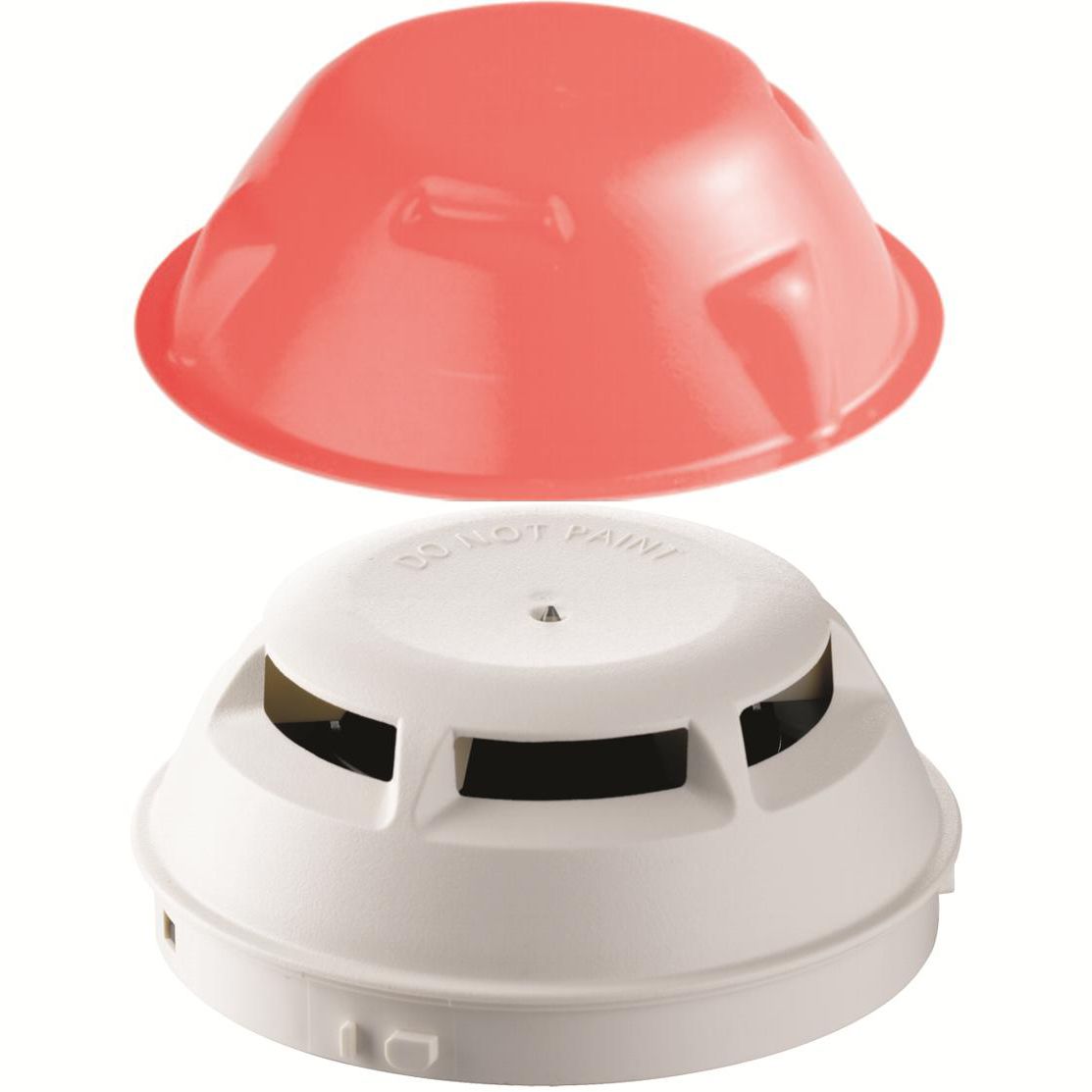
- Detector contamination or sensor aging can cause nuisance alarms or reduced sensitivity, noticed as repeated false alarms or failed tests
- Open or short circuits in loops and zones can isolate devices, shown by fault indications at the panel
- Power-supply or battery faults can reduce system availability, seen as charger, supply or standby-power alarms
- Addressing or configuration errors can identify the wrong device or zone, noticed during functional testing
- Moisture, corrosion or loose terminals can create intermittent faults, seen as unstable loop status or recurring device communication alarms
- Detector contamination or sensor aging can cause nuisance alarms or reduced sensitivity, noticed as repeated false alarms or failed tests
- Open or short circuits in loops and zones can isolate devices, shown by fault indications at the panel
- Power-supply or battery faults can reduce system availability, seen as charger, supply or standby-power alarms
- Addressing or configuration errors can identify the wrong device or zone, noticed during functional testing
- Moisture, corrosion or loose terminals can create intermittent faults, seen as unstable loop status or recurring device communication alarms
- Detector contamination or sensor aging can cause nuisance alarms or reduced sensitivity, noticed as repeated false alarms or failed tests
- Open or short circuits in loops and zones can isolate devices, shown by fault indications at the panel
- Power-supply or battery faults can reduce system availability, seen as charger, supply or standby-power alarms
- Addressing or configuration errors can identify the wrong device or zone, noticed during functional testing
- Moisture, corrosion or loose terminals can create intermittent faults, seen as unstable loop status or recurring device communication alarms
- Detector contamination or sensor aging can cause nuisance alarms or reduced sensitivity, noticed as repeated false alarms or failed tests
- Open or short circuits in loops and zones can isolate devices, shown by fault indications at the panel
- Power-supply or battery faults can reduce system availability, seen as charger, supply or standby-power alarms
- Addressing or configuration errors can identify the wrong device or zone, noticed during functional testing
- Moisture, corrosion or loose terminals can create intermittent faults, seen as unstable loop status or recurring device communication alarms
- Detector contamination or sensor aging can cause nuisance alarms or reduced sensitivity, noticed as repeated false alarms or failed tests
- Open or short circuits in loops and zones can isolate devices, shown by fault indications at the panel
- Power-supply or battery faults can reduce system availability, seen as charger, supply or standby-power alarms
- Addressing or configuration errors can identify the wrong device or zone, noticed during functional testing
- Moisture, corrosion or loose terminals can create intermittent faults, seen as unstable loop status or recurring device communication alarms
- Detector contamination or sensor aging can cause nuisance alarms or reduced sensitivity, noticed as repeated false alarms or failed tests
- Open or short circuits in loops and zones can isolate devices, shown by fault indications at the panel
- Power-supply or battery faults can reduce system availability, seen as charger, supply or standby-power alarms
- Addressing or configuration errors can identify the wrong device or zone, noticed during functional testing
- Moisture, corrosion or loose terminals can create intermittent faults, seen as unstable loop status or recurring device communication alarms
- Detector contamination or sensor aging can cause nuisance alarms or reduced sensitivity, noticed as repeated false alarms or failed tests
- Open or short circuits in loops and zones can isolate devices, shown by fault indications at the panel
- Power-supply or battery faults can reduce system availability, seen as charger, supply or standby-power alarms
- Addressing or configuration errors can identify the wrong device or zone, noticed during functional testing
- Moisture, corrosion or loose terminals can create intermittent faults, seen as unstable loop status or recurring device communication alarms
Autronica / Honeywell
10- Detector or sensing-element contamination, poisoning or ageing can cause false alarms, slow response or failed functional tests
- Battery, power-supply or control-circuit faults caused by ageing, loose wiring or blown protection can lead to trouble alarms or unavailable safety functions
- Cylinder pressure loss, leakage or damaged valves where stored media is used can leave the equipment outside ready condition and may be found during inspection or weighing checks
- Blocked, corroded or mechanically damaged nozzles, piping, hoses or masks can restrict discharge or breathing flow and show as poor functional test results
- Incorrect isolation, expired service status or disturbed release interlocks after maintenance can prevent normal arming and create panel faults or failed readiness checks
- Blocked, damaged, corroded, or contaminated detectors, nozzles, piping, valves, or release components reduce coverage or prevent correct discharge
- Loss of extinguishing medium, pressure, water supply, or foam concentrate causes low-level indications, failed tests, or reduced firefighting capability
- Control-panel, power-supply, loop, cable, or communication faults produce alarms, disabled zones, or loss of remote release
- Valve, damper, actuator, or interlock faults prevent the required shutdown, isolation, or agent release sequence
- Poor maintenance, incorrect line-up, or obstructed access is identified during tests and can delay emergency response
- Detector or sensing-element contamination, poisoning or ageing can cause false alarms, slow response or failed functional tests
- Battery, power-supply or control-circuit faults caused by ageing, loose wiring or blown protection can lead to trouble alarms or unavailable safety functions
- Cylinder pressure loss, leakage or damaged valves where stored media is used can leave the equipment outside ready condition and may be found during inspection or weighing checks
- Blocked, corroded or mechanically damaged nozzles, piping, hoses or masks can restrict discharge or breathing flow and show as poor functional test results
- Incorrect isolation, expired service status or disturbed release interlocks after maintenance can prevent normal arming and create panel faults or failed readiness checks
- Detector contamination or sensor aging can cause nuisance alarms or reduced sensitivity, noticed as repeated false alarms or failed tests
- Open or short circuits in loops and zones can isolate devices, shown by fault indications at the panel
- Power-supply or battery faults can reduce system availability, seen as charger, supply or standby-power alarms
- Addressing or configuration errors can identify the wrong device or zone, noticed during functional testing
- Moisture, corrosion or loose terminals can create intermittent faults, seen as unstable loop status or recurring device communication alarms
- Detector contamination or sensor aging can cause nuisance alarms or reduced sensitivity, noticed as repeated false alarms or failed tests
- Open or short circuits in loops and zones can isolate devices, shown by fault indications at the panel
- Power-supply or battery faults can reduce system availability, seen as charger, supply or standby-power alarms
- Addressing or configuration errors can identify the wrong device or zone, noticed during functional testing
- Moisture, corrosion or loose terminals can create intermittent faults, seen as unstable loop status or recurring device communication alarms
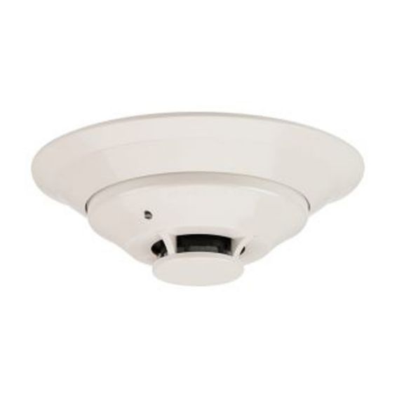
- Detector contamination or sensor aging can cause nuisance alarms or reduced sensitivity, noticed as repeated false alarms or failed tests
- Open or short circuits in loops and zones can isolate devices, shown by fault indications at the panel
- Power-supply or battery faults can reduce system availability, seen as charger, supply or standby-power alarms
- Addressing or configuration errors can identify the wrong device or zone, noticed during functional testing
- Moisture, corrosion or loose terminals can create intermittent faults, seen as unstable loop status or recurring device communication alarms
- Detector contamination or sensor aging can cause nuisance alarms or reduced sensitivity, noticed as repeated false alarms or failed tests
- Open or short circuits in loops and zones can isolate devices, shown by fault indications at the panel
- Power-supply or battery faults can reduce system availability, seen as charger, supply or standby-power alarms
- Addressing or configuration errors can identify the wrong device or zone, noticed during functional testing
- Moisture, corrosion or loose terminals can create intermittent faults, seen as unstable loop status or recurring device communication alarms
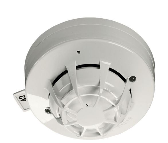
- Detector contamination or sensor aging can cause nuisance alarms or reduced sensitivity, noticed as repeated false alarms or failed tests
- Open or short circuits in loops and zones can isolate devices, shown by fault indications at the panel
- Power-supply or battery faults can reduce system availability, seen as charger, supply or standby-power alarms
- Addressing or configuration errors can identify the wrong device or zone, noticed during functional testing
- Moisture, corrosion or loose terminals can create intermittent faults, seen as unstable loop status or recurring device communication alarms
- Detector contamination or sensor aging can cause nuisance alarms or reduced sensitivity, noticed as repeated false alarms or failed tests
- Open or short circuits in loops and zones can isolate devices, shown by fault indications at the panel
- Power-supply or battery faults can reduce system availability, seen as charger, supply or standby-power alarms
- Addressing or configuration errors can identify the wrong device or zone, noticed during functional testing
- Moisture, corrosion or loose terminals can create intermittent faults, seen as unstable loop status or recurring device communication alarms
- Detector contamination or sensor aging can cause nuisance alarms or reduced sensitivity, noticed as repeated false alarms or failed tests
- Open or short circuits in loops and zones can isolate devices, shown by fault indications at the panel
- Power-supply or battery faults can reduce system availability, seen as charger, supply or standby-power alarms
- Addressing or configuration errors can identify the wrong device or zone, noticed during functional testing
- Moisture, corrosion or loose terminals can create intermittent faults, seen as unstable loop status or recurring device communication alarms
Consilium Marine
10- Blocked, damaged, corroded, or contaminated detectors, nozzles, piping, valves, or release components reduce coverage or prevent correct discharge
- Loss of extinguishing medium, pressure, water supply, or foam concentrate causes low-level indications, failed tests, or reduced firefighting capability
- Control-panel, power-supply, loop, cable, or communication faults produce alarms, disabled zones, or loss of remote release
- Valve, damper, actuator, or interlock faults prevent the required shutdown, isolation, or agent release sequence
- Poor maintenance, incorrect line-up, or obstructed access is identified during tests and can delay emergency response
- Blocked, damaged, corroded, or contaminated detectors, nozzles, piping, valves, or release components reduce coverage or prevent correct discharge
- Loss of extinguishing medium, pressure, water supply, or foam concentrate causes low-level indications, failed tests, or reduced firefighting capability
- Control-panel, power-supply, loop, cable, or communication faults produce alarms, disabled zones, or loss of remote release
- Valve, damper, actuator, or interlock faults prevent the required shutdown, isolation, or agent release sequence
- Poor maintenance, incorrect line-up, or obstructed access is identified during tests and can delay emergency response
- Blocked, damaged, corroded, or contaminated detectors, nozzles, piping, valves, or release components reduce coverage or prevent correct discharge
- Loss of extinguishing medium, pressure, water supply, or foam concentrate causes low-level indications, failed tests, or reduced firefighting capability
- Control-panel, power-supply, loop, cable, or communication faults produce alarms, disabled zones, or loss of remote release
- Valve, damper, actuator, or interlock faults prevent the required shutdown, isolation, or agent release sequence
- Poor maintenance, incorrect line-up, or obstructed access is identified during tests and can delay emergency response
- Detector contamination or sensor aging can cause nuisance alarms or reduced sensitivity, noticed as repeated false alarms or failed tests
- Open or short circuits in loops and zones can isolate devices, shown by fault indications at the panel
- Power-supply or battery faults can reduce system availability, seen as charger, supply or standby-power alarms
- Addressing or configuration errors can identify the wrong device or zone, noticed during functional testing
- Moisture, corrosion or loose terminals can create intermittent faults, seen as unstable loop status or recurring device communication alarms
- Detector contamination or sensor aging can cause nuisance alarms or reduced sensitivity, noticed as repeated false alarms or failed tests
- Open or short circuits in loops and zones can isolate devices, shown by fault indications at the panel
- Power-supply or battery faults can reduce system availability, seen as charger, supply or standby-power alarms
- Addressing or configuration errors can identify the wrong device or zone, noticed during functional testing
- Moisture, corrosion or loose terminals can create intermittent faults, seen as unstable loop status or recurring device communication alarms
- Detector contamination or sensor aging can cause nuisance alarms or reduced sensitivity, noticed as repeated false alarms or failed tests
- Open or short circuits in loops and zones can isolate devices, shown by fault indications at the panel
- Power-supply or battery faults can reduce system availability, seen as charger, supply or standby-power alarms
- Addressing or configuration errors can identify the wrong device or zone, noticed during functional testing
- Moisture, corrosion or loose terminals can create intermittent faults, seen as unstable loop status or recurring device communication alarms
- Detector contamination or sensor aging can cause nuisance alarms or reduced sensitivity, noticed as repeated false alarms or failed tests
- Open or short circuits in loops and zones can isolate devices, shown by fault indications at the panel
- Power-supply or battery faults can reduce system availability, seen as charger, supply or standby-power alarms
- Addressing or configuration errors can identify the wrong device or zone, noticed during functional testing
- Moisture, corrosion or loose terminals can create intermittent faults, seen as unstable loop status or recurring device communication alarms
- Detector contamination or sensor aging can cause nuisance alarms or reduced sensitivity, noticed as repeated false alarms or failed tests
- Open or short circuits in loops and zones can isolate devices, shown by fault indications at the panel
- Power-supply or battery faults can reduce system availability, seen as charger, supply or standby-power alarms
- Addressing or configuration errors can identify the wrong device or zone, noticed during functional testing
- Moisture, corrosion or loose terminals can create intermittent faults, seen as unstable loop status or recurring device communication alarms
- Detector contamination or sensor aging can cause nuisance alarms or reduced sensitivity, noticed as repeated false alarms or failed tests
- Open or short circuits in loops and zones can isolate devices, shown by fault indications at the panel
- Power-supply or battery faults can reduce system availability, seen as charger, supply or standby-power alarms
- Addressing or configuration errors can identify the wrong device or zone, noticed during functional testing
- Moisture, corrosion or loose terminals can create intermittent faults, seen as unstable loop status or recurring device communication alarms
- Detector contamination or sensor aging can cause nuisance alarms or reduced sensitivity, noticed as repeated false alarms or failed tests
- Open or short circuits in loops and zones can isolate devices, shown by fault indications at the panel
- Power-supply or battery faults can reduce system availability, seen as charger, supply or standby-power alarms
- Addressing or configuration errors can identify the wrong device or zone, noticed during functional testing
- Moisture, corrosion or loose terminals can create intermittent faults, seen as unstable loop status or recurring device communication alarms
Esser / Honeywell
10- Detector or sensing-element contamination, poisoning or ageing can cause false alarms, slow response or failed functional tests
- Battery, power-supply or control-circuit faults caused by ageing, loose wiring or blown protection can lead to trouble alarms or unavailable safety functions
- Cylinder pressure loss, leakage or damaged valves where stored media is used can leave the equipment outside ready condition and may be found during inspection or weighing checks
- Blocked, corroded or mechanically damaged nozzles, piping, hoses or masks can restrict discharge or breathing flow and show as poor functional test results
- Incorrect isolation, expired service status or disturbed release interlocks after maintenance can prevent normal arming and create panel faults or failed readiness checks
- Detector or sensing-element contamination, poisoning or ageing can cause false alarms, slow response or failed functional tests
- Battery, power-supply or control-circuit faults caused by ageing, loose wiring or blown protection can lead to trouble alarms or unavailable safety functions
- Cylinder pressure loss, leakage or damaged valves where stored media is used can leave the equipment outside ready condition and may be found during inspection or weighing checks
- Blocked, corroded or mechanically damaged nozzles, piping, hoses or masks can restrict discharge or breathing flow and show as poor functional test results
- Incorrect isolation, expired service status or disturbed release interlocks after maintenance can prevent normal arming and create panel faults or failed readiness checks
- Blocked, damaged, corroded, or contaminated detectors, nozzles, piping, valves, or release components reduce coverage or prevent correct discharge
- Loss of extinguishing medium, pressure, water supply, or foam concentrate causes low-level indications, failed tests, or reduced firefighting capability
- Control-panel, power-supply, loop, cable, or communication faults produce alarms, disabled zones, or loss of remote release
- Valve, damper, actuator, or interlock faults prevent the required shutdown, isolation, or agent release sequence
- Poor maintenance, incorrect line-up, or obstructed access is identified during tests and can delay emergency response
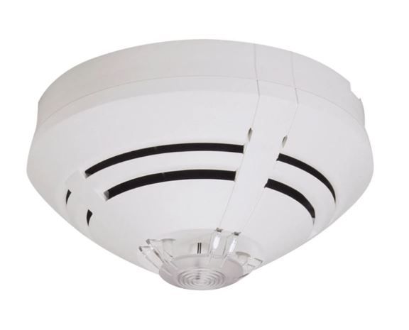
- Detector or sensing-element contamination caused by dust, grease, moisture or aging, resulting in false alarms, slow response or fault indication
- Loop or cable fault caused by damaged wiring, loose terminals or earth leakage, resulting in missing devices or intermittent system faults
- Addressing or configuration error caused by replacement or software changes, resulting in incorrect device identification or unavailable zones
- Power-supply or backup-battery deterioration caused by charger faults or aged batteries, resulting in power alarms or reduced standby capability
- Panel, relay or communication failure caused by electronics faults, resulting in missing alarms, failed outputs or loss of connection to other safety systems
- Detector or sensing-element contamination caused by dust, grease, moisture or aging, resulting in false alarms, slow response or fault indication
- Loop or cable fault caused by damaged wiring, loose terminals or earth leakage, resulting in missing devices or intermittent system faults
- Addressing or configuration error caused by replacement or software changes, resulting in incorrect device identification or unavailable zones
- Power-supply or backup-battery deterioration caused by charger faults or aged batteries, resulting in power alarms or reduced standby capability
- Panel, relay or communication failure caused by electronics faults, resulting in missing alarms, failed outputs or loss of connection to other safety systems
- Detector contamination or sensor aging can cause nuisance alarms or reduced sensitivity, noticed as repeated false alarms or failed tests
- Open or short circuits in loops and zones can isolate devices, shown by fault indications at the panel
- Power-supply or battery faults can reduce system availability, seen as charger, supply or standby-power alarms
- Addressing or configuration errors can identify the wrong device or zone, noticed during functional testing
- Moisture, corrosion or loose terminals can create intermittent faults, seen as unstable loop status or recurring device communication alarms
- Detector or sensing-element contamination caused by dust, grease, moisture or aging, resulting in false alarms, slow response or fault indication
- Loop or cable fault caused by damaged wiring, loose terminals or earth leakage, resulting in missing devices or intermittent system faults
- Addressing or configuration error caused by replacement or software changes, resulting in incorrect device identification or unavailable zones
- Power-supply or backup-battery deterioration caused by charger faults or aged batteries, resulting in power alarms or reduced standby capability
- Panel, relay or communication failure caused by electronics faults, resulting in missing alarms, failed outputs or loss of connection to other safety systems
- Detector or sensing-element contamination caused by dust, grease, moisture or aging, resulting in false alarms, slow response or fault indication
- Loop or cable fault caused by damaged wiring, loose terminals or earth leakage, resulting in missing devices or intermittent system faults
- Addressing or configuration error caused by replacement or software changes, resulting in incorrect device identification or unavailable zones
- Power-supply or backup-battery deterioration caused by charger faults or aged batteries, resulting in power alarms or reduced standby capability
- Panel, relay or communication failure caused by electronics faults, resulting in missing alarms, failed outputs or loss of connection to other safety systems
- Detector or sensing-element contamination caused by dust, grease, moisture or aging, resulting in false alarms, slow response or fault indication
- Loop or cable fault caused by damaged wiring, loose terminals or earth leakage, resulting in missing devices or intermittent system faults
- Addressing or configuration error caused by replacement or software changes, resulting in incorrect device identification or unavailable zones
- Power-supply or backup-battery deterioration caused by charger faults or aged batteries, resulting in power alarms or reduced standby capability
- Panel, relay or communication failure caused by electronics faults, resulting in missing alarms, failed outputs or loss of connection to other safety systems
- Detector or sensing-element contamination caused by dust, grease, moisture or aging, resulting in false alarms, slow response or fault indication
- Loop or cable fault caused by damaged wiring, loose terminals or earth leakage, resulting in missing devices or intermittent system faults
- Addressing or configuration error caused by replacement or software changes, resulting in incorrect device identification or unavailable zones
- Power-supply or backup-battery deterioration caused by charger faults or aged batteries, resulting in power alarms or reduced standby capability
- Panel, relay or communication failure caused by electronics faults, resulting in missing alarms, failed outputs or loss of connection to other safety systems
Notifier / Honeywell
10- Detector or sensing-element contamination, poisoning or ageing can cause false alarms, slow response or failed functional tests
- Battery, power-supply or control-circuit faults caused by ageing, loose wiring or blown protection can lead to trouble alarms or unavailable safety functions
- Cylinder pressure loss, leakage or damaged valves where stored media is used can leave the equipment outside ready condition and may be found during inspection or weighing checks
- Blocked, corroded or mechanically damaged nozzles, piping, hoses or masks can restrict discharge or breathing flow and show as poor functional test results
- Incorrect isolation, expired service status or disturbed release interlocks after maintenance can prevent normal arming and create panel faults or failed readiness checks
- Detector or sensing-element contamination, poisoning or ageing can cause false alarms, slow response or failed functional tests
- Battery, power-supply or control-circuit faults caused by ageing, loose wiring or blown protection can lead to trouble alarms or unavailable safety functions
- Cylinder pressure loss, leakage or damaged valves where stored media is used can leave the equipment outside ready condition and may be found during inspection or weighing checks
- Blocked, corroded or mechanically damaged nozzles, piping, hoses or masks can restrict discharge or breathing flow and show as poor functional test results
- Incorrect isolation, expired service status or disturbed release interlocks after maintenance can prevent normal arming and create panel faults or failed readiness checks
- Detector contamination or sensor aging can cause nuisance alarms or reduced sensitivity, noticed as repeated false alarms or failed tests
- Open or short circuits in loops and zones can isolate devices, shown by fault indications at the panel
- Power-supply or battery faults can reduce system availability, seen as charger, supply or standby-power alarms
- Addressing or configuration errors can identify the wrong device or zone, noticed during functional testing
- Moisture, corrosion or loose terminals can create intermittent faults, seen as unstable loop status or recurring device communication alarms
- Detector contamination or sensor aging can cause nuisance alarms or reduced sensitivity, noticed as repeated false alarms or failed tests
- Open or short circuits in loops and zones can isolate devices, shown by fault indications at the panel
- Power-supply or battery faults can reduce system availability, seen as charger, supply or standby-power alarms
- Addressing or configuration errors can identify the wrong device or zone, noticed during functional testing
- Moisture, corrosion or loose terminals can create intermittent faults, seen as unstable loop status or recurring device communication alarms
- Detector contamination or sensor aging can cause nuisance alarms or reduced sensitivity, noticed as repeated false alarms or failed tests
- Open or short circuits in loops and zones can isolate devices, shown by fault indications at the panel
- Power-supply or battery faults can reduce system availability, seen as charger, supply or standby-power alarms
- Addressing or configuration errors can identify the wrong device or zone, noticed during functional testing
- Moisture, corrosion or loose terminals can create intermittent faults, seen as unstable loop status or recurring device communication alarms
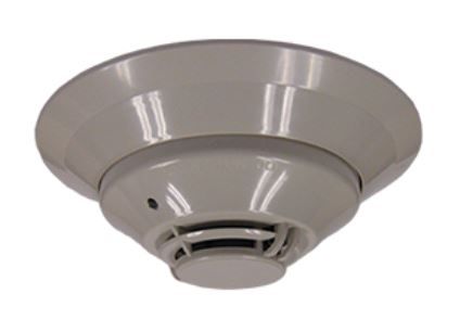
- Detector contamination or sensor aging can cause nuisance alarms or reduced sensitivity, noticed as repeated false alarms or failed tests
- Open or short circuits in loops and zones can isolate devices, shown by fault indications at the panel
- Power-supply or battery faults can reduce system availability, seen as charger, supply or standby-power alarms
- Addressing or configuration errors can identify the wrong device or zone, noticed during functional testing
- Moisture, corrosion or loose terminals can create intermittent faults, seen as unstable loop status or recurring device communication alarms
- Detector contamination or sensor aging can cause nuisance alarms or reduced sensitivity, noticed as repeated false alarms or failed tests
- Open or short circuits in loops and zones can isolate devices, shown by fault indications at the panel
- Power-supply or battery faults can reduce system availability, seen as charger, supply or standby-power alarms
- Addressing or configuration errors can identify the wrong device or zone, noticed during functional testing
- Moisture, corrosion or loose terminals can create intermittent faults, seen as unstable loop status or recurring device communication alarms
- Detector or sensing-element contamination caused by dust, grease, moisture or aging, resulting in false alarms, slow response or fault indication
- Loop or cable fault caused by damaged wiring, loose terminals or earth leakage, resulting in missing devices or intermittent system faults
- Addressing or configuration error caused by replacement or software changes, resulting in incorrect device identification or unavailable zones
- Power-supply or backup-battery deterioration caused by charger faults or aged batteries, resulting in power alarms or reduced standby capability
- Panel, relay or communication failure caused by electronics faults, resulting in missing alarms, failed outputs or loss of connection to other safety systems
- Detector or sensing-element contamination caused by dust, grease, moisture or aging, resulting in false alarms, slow response or fault indication
- Loop or cable fault caused by damaged wiring, loose terminals or earth leakage, resulting in missing devices or intermittent system faults
- Addressing or configuration error caused by replacement or software changes, resulting in incorrect device identification or unavailable zones
- Power-supply or backup-battery deterioration caused by charger faults or aged batteries, resulting in power alarms or reduced standby capability
- Panel, relay or communication failure caused by electronics faults, resulting in missing alarms, failed outputs or loss of connection to other safety systems
Xtralis / Honeywell
9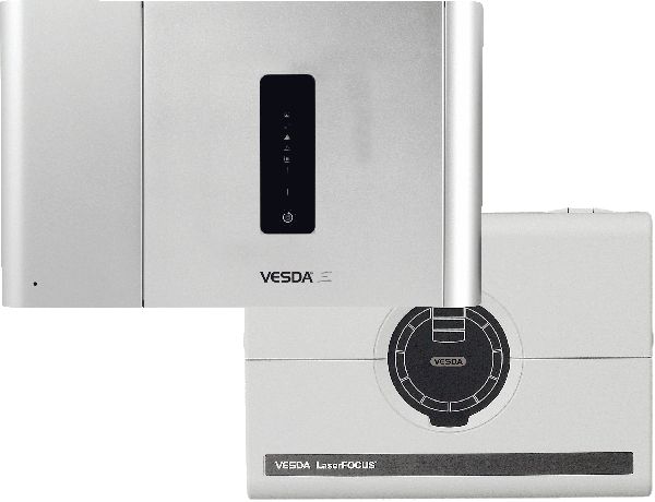
- Blocked, damaged, corroded, or contaminated detectors, nozzles, piping, valves, or release components reduce coverage or prevent correct discharge
- Loss of extinguishing medium, pressure, water supply, or foam concentrate causes low-level indications, failed tests, or reduced firefighting capability
- Control-panel, power-supply, loop, cable, or communication faults produce alarms, disabled zones, or loss of remote release
- Valve, damper, actuator, or interlock faults prevent the required shutdown, isolation, or agent release sequence
- Poor maintenance, incorrect line-up, or obstructed access is identified during tests and can delay emergency response
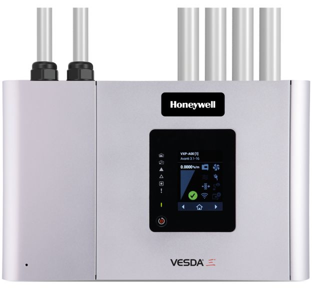
- Detector contamination or ageing, typically indicated by false alarms, reduced sensitivity or detector fault indication
- Loop wiring open/short circuit from cable or terminal damage, typically indicated by zone/loop fault alarms and loss of multiple devices
- Power-supply or backup-battery failure, typically indicated by panel power alarms or loss of standby capability
- Addressable module or panel electronics fault, typically indicated by missing devices, communication errors or unstable indications
- Incorrect detector placement/obstruction or damaged sensing path, typically indicated by slow or unreliable detection during testing
- Dust, salt, oil or contamination at the sensing element causes false alarms, reduced sensitivity or failed tests
- Water ingress or condensation causes intermittent alarms or detector failure
- Loop wiring, base or address faults cause missing-device or communication alarms
- Paint, covers or physical obstruction prevents the detector from sensing the protected space correctly
- Ageing electronics or sensor deterioration causes repeated nuisance alarms or failure during test
- Detector contamination or ageing, typically indicated by false alarms, reduced sensitivity or detector fault indication
- Loop wiring open/short circuit from cable or terminal damage, typically indicated by zone/loop fault alarms and loss of multiple devices
- Power-supply or backup-battery failure, typically indicated by panel power alarms or loss of standby capability
- Addressable module or panel electronics fault, typically indicated by missing devices, communication errors or unstable indications
- Incorrect detector placement/obstruction or damaged sensing path, typically indicated by slow or unreliable detection during testing
- Dust, salt, oil or contamination at the sensing element causes false alarms, reduced sensitivity or failed tests
- Water ingress or condensation causes intermittent alarms or detector failure
- Loop wiring, base or address faults cause missing-device or communication alarms
- Paint, covers or physical obstruction prevents the detector from sensing the protected space correctly
- Ageing electronics or sensor deterioration causes repeated nuisance alarms or failure during test
- Dust, salt, oil or contamination at the sensing element causes false alarms, reduced sensitivity or failed tests
- Water ingress or condensation causes intermittent alarms or detector failure
- Loop wiring, base or address faults cause missing-device or communication alarms
- Paint, covers or physical obstruction prevents the detector from sensing the protected space correctly
- Ageing electronics or sensor deterioration causes repeated nuisance alarms or failure during test
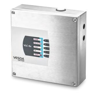
- Dust, salt, oil or contamination at the sensing element causes false alarms, reduced sensitivity or failed tests
- Water ingress or condensation causes intermittent alarms or detector failure
- Loop wiring, base or address faults cause missing-device or communication alarms
- Paint, covers or physical obstruction prevents the detector from sensing the protected space correctly
- Ageing electronics or sensor deterioration causes repeated nuisance alarms or failure during test
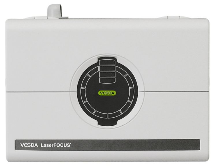
- Dust, salt, oil or contamination at the sensing element causes false alarms, reduced sensitivity or failed tests
- Water ingress or condensation causes intermittent alarms or detector failure
- Loop wiring, base or address faults cause missing-device or communication alarms
- Paint, covers or physical obstruction prevents the detector from sensing the protected space correctly
- Ageing electronics or sensor deterioration causes repeated nuisance alarms or failure during test
- Dust, salt, oil or contamination at the sensing element causes false alarms, reduced sensitivity or failed tests
- Water ingress or condensation causes intermittent alarms or detector failure
- Loop wiring, base or address faults cause missing-device or communication alarms
- Paint, covers or physical obstruction prevents the detector from sensing the protected space correctly
- Ageing electronics or sensor deterioration causes repeated nuisance alarms or failure during test
Det-Tronics
2- Dust, paint or contamination obstructs the sensing chamber and causes false alarms or reduced sensitivity
- Water ingress or corrosion causes intermittent faults or complete detector failure
- Loose loop wiring or base contacts produces open-circuit or device-fault indications
- Incorrect detector addressing or configuration causes the alarm to appear at the wrong location
- Ageing sensing components may fail functional testing or become prone to nuisance alarms
- Dust, paint or contamination obstructs the sensing chamber and causes false alarms or reduced sensitivity
- Water ingress or corrosion causes intermittent faults or complete detector failure
- Loose loop wiring or base contacts produces open-circuit or device-fault indications
- Incorrect detector addressing or configuration causes the alarm to appear at the wrong location
- Ageing sensing components may fail functional testing or become prone to nuisance alarms
Hochiki / FFE
2- Detector or sensing-element contamination, poisoning or ageing can cause false alarms, slow response or failed functional tests
- Battery, power-supply or control-circuit faults caused by ageing, loose wiring or blown protection can lead to trouble alarms or unavailable safety functions
- Cylinder pressure loss, leakage or damaged valves where stored media is used can leave the equipment outside ready condition and may be found during inspection or weighing checks
- Blocked, corroded or mechanically damaged nozzles, piping, hoses or masks can restrict discharge or breathing flow and show as poor functional test results
- Incorrect isolation, expired service status or disturbed release interlocks after maintenance can prevent normal arming and create panel faults or failed readiness checks
- Detector or sensing-element contamination, poisoning or ageing can cause false alarms, slow response or failed functional tests
- Battery, power-supply or control-circuit faults caused by ageing, loose wiring or blown protection can lead to trouble alarms or unavailable safety functions
- Cylinder pressure loss, leakage or damaged valves where stored media is used can leave the equipment outside ready condition and may be found during inspection or weighing checks
- Blocked, corroded or mechanically damaged nozzles, piping, hoses or masks can restrict discharge or breathing flow and show as poor functional test results
- Incorrect isolation, expired service status or disturbed release interlocks after maintenance can prevent normal arming and create panel faults or failed readiness checks