What to check on a Bollard.
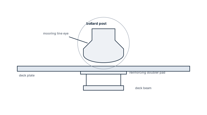
A bollard looks like the simplest piece of equipment on deck, but it carries some of the highest concentrated loads a ship's structure sees: the full pull of a mooring line, sometimes two lines crossed on the same pair of posts, transmitted through a small footprint into the deck plating. What makes a bollard fit for purpose is not the casting itself, which is usually a straightforward design, but the doubler plates, brackets and reinforcement welded beneath the deck to spread that load into the surrounding structure. A bollard bolted…
What sets a bollard apart
A bollard looks like the simplest piece of equipment on deck, but it carries some of the highest concentrated loads a ship's structure sees: the full pull of a mooring line, sometimes two lines crossed on the same pair of posts, transmitted through a small footprint into the deck plating. What makes a bollard fit for purpose is not the casting itself, which is usually a straightforward design, but the doubler plates, brackets and reinforcement welded beneath the deck to spread that load into the surrounding structure. A bollard bolted or welded onto unreinforced deck plating will eventually tear the plating around its base long before the casting itself fails. This is the key distinction from other deck fittings such as padeyes or fairleads: a bollard is rated by the mooring line load path through the whole local structure, not by the strength of the fitting in isolation.
Main types
- Single bollard — one post, used for lighter duty or where deck space is tight
- Double (twin) bollard — the standard mooring bollard, two posts on a common base allowing a line to be figure-eighted for a secure, adjustable hold
- Bitts — a related fitting, typically lower and heavier, common at the towing point or where very high loads concentrate
- Warping drum end posts — bollards that double as a powered warping point on some vessels
Selection and sizing
- Safe working load matched to the mooring line pull the fitting is expected to take, per the ship's mooring arrangement plan
- Base plate and underdeck reinforcement designed together with the bollard, not specified as separate items
- Post diameter and height suited to the mooring line size actually used, so the line does not chafe on a post that is too small
- Position relative to fairleads, so the mooring line runs at a fair lead angle rather than across a sharp edge
Regulations and class
Classification society rules for mooring equipment set the required safe working loads for bollards based on the ship's equipment number, and specify how the load is to be verified through the deck structure, not just the casting. Survey checks include visual inspection for cracking at the weld toe between bollard and deck, a common fatigue point given the cyclic loading mooring lines apply.
Typical faults
| Fault | Cause | Consequence |
|---|---|---|
| Weld cracking at the base | Fatigue from repeated mooring loads, or a single overload event | Progressive weakening, risk of the bollard tearing free under load |
| Deck plating deformation around the base | Inadequate underdeck reinforcement for the loads actually applied | Local structural damage that can spread if not repaired |
| Wasted or grooved post surface | Years of mooring line chafe against the same contact point | Reduced post diameter concentrates load on the mooring line and accelerates line wear |
| Corrosion at the deck-to-base joint | Trapped moisture at a poorly sealed base joint | Hidden thinning of the base plate, only found on close inspection |
What to look for in a supplier
- A bollard supplied with a matching underdeck reinforcement drawing, not the casting alone
- Safe working load certification tied to the ship's actual equipment number, not a generic catalogue rating
- Post dimensions suited to the mooring line size in service, confirmed against current line diameter rather than the original build specification if lines have since changed
- Welding procedure and material grade compatible with the surrounding deck steel
Look under the deck, not just at the bollard, during inspection: cracking or deformation in the reinforcement below is often the true early warning, and it is invisible from the deck surface where everyone normally looks.