OceanSphere
Engines
Also listed under Navigation & Bridge Equipment (16 models)

Inmarsat Terminal

medium 134 / 134 models (Inspector)

An Inmarsat terminal provides GMDSS-approved satellite distress alerting and two-way communication through Inmarsat's geostationary satellite network, giving near-global coverage except at the high latitudes the satellites cannot see, which is why polar-trading vessels still need an Iridium or HF alternative.

Read more — Inmarsat Terminal explained

What defines this type

An Inmarsat terminal is a satellite communication unit certified for GMDSS use that links the ship to Inmarsat's geostationary satellite constellation for distress alerting, safety information reception and general voice or data communication. Its defining limitation is geometric: geostationary satellites sit over the equator, so coverage weakens and eventually disappears above roughly 70 to 76 degrees latitude depending on the specific satellite and antenna, which is why GMDSS regulations recognise Inmarsat as satisfying sea area A3 coverage but not the polar sea area A4, where an alternative such as an Iridium terminal or HF/MF radio is required instead. This distinguishes it from Iridium-based GMDSS terminals, which use a low-earth-orbit constellation with genuine pole-to-pole coverage but a different antenna and service architecture.

Inmarsat terminal shipboard arrangement
Ship profile showing the stabilised above-deck antenna in its radome on the mast, the RF cable running down to the below-deck unit in the radio room, and its connections to the distress button, handset/telex terminal and backup power supply.

Main components

  • Above-deck unit: a stabilised parabolic or phased-array antenna that tracks the satellite as the ship moves and rolls, housed in a radome
  • Below-deck transceiver unit handling modulation, GMDSS distress button logic and interface to the bridge alarm panel
  • Distress button, a dedicated, guarded, spring-loaded control that transmits a distress alert with the ship's identity and position directly, bypassing normal message routing
  • Power supply from the ship's main and emergency source, since GMDSS equipment must function on emergency power
  • Interface to the ship's GPS or GNSS receiver, since the distress alert must include current position

Selection and sizing

  • GMDSS sea area the vessel actually trades in, which determines whether an Inmarsat terminal alone satisfies the carriage requirement or must be paired with another system for area A4
  • Service type: FleetBroadband and similar terminals combine GMDSS distress functions with commercial voice and broadband data, while older, simpler terminals may provide GMDSS functions only
  • Antenna size, since a larger stabilised antenna gives a more reliable link in heavy weather and higher data rates for commercial use, at greater installed cost and deck space
  • Redundant power and cabling routing so the antenna and transceiver survive the same casualty scenario the distress function is meant to respond to

Regulations and class

SOLAS Chapter IV sets the GMDSS carriage requirements by sea area, specifying which combination of satellite and radio equipment a vessel must carry for the areas it operates in. IMO performance standards for Inmarsat ship earth stations set the technical requirements a type-approved terminal must meet, covering distress priority, automatic position inclusion and power backup. Class and flag administration surveys verify the terminal's GMDSS certification is current, that battery backup meets the required endurance, and that the distress button and alarm panel interface function correctly at each periodic survey.

Typical faults

FaultCauseConsequence
Loss of satellite lock in heavy weatherAntenna stabilisation unable to track through severe roll and pitchCommunication drops exactly when weather-related distress risk is higher
No position included in distress alertGNSS interface fault or lost GPS fixDistress alert transmits without position, delaying rescue coordination
Radome or antenna dome damageAge, UV degradation, or physical impact from cargo operations nearbyWater ingress affecting antenna electronics, degraded signal
Battery backup fails endurance testBattery age not tracked against the required replacement intervalGMDSS function unavailable during a mains power loss, the exact scenario it exists for

What to look for in a supplier

  • Current GMDSS type approval and confirmation of which sea areas the specific model satisfies on its own versus in combination with other equipment
  • Service and airtime provider coverage matching the vessel's actual trading pattern, not just a headline global coverage claim
  • Battery backup replacement and testing regime clearly documented for the surveyor
  • Antenna stabilisation performance specification for the sea states the vessel actually encounters

Confirm which GMDSS sea area a specific Inmarsat terminal model is actually approved for before assuming it covers the vessel's full trading pattern, since equipment satisfying area A3 does not automatically extend to A4.

Inspector Mode Show All 134 / 134 with inspector value

10 manufacturers · 134 models

Intellian

27
v60Ka unverified
Type
VSAT
Stabilized
ja
Common Failures & Inspection Points
  • Antenna obstruction, tracking fault or damaged radome causes loss of satellite lock, poor signal quality or repeated connection drops
  • Modem, terminal or network-interface failure causes unavailable data or voice services despite normal ship power
  • Power-supply or UPS faults cause terminal rebooting, blank displays or complete service loss
  • Cabling, connector or Ethernet faults cause intermittent connectivity or loss of interfaces to ship systems
  • Configuration, registration or service-provider problems prevent log-in or message transfer even when hardware tests appear normal
Service: Inspect antenna or radome, mounting, cabling, indoor units, power supply and network interfaces. Review signal-quality and terminal logs for recurring dropouts. Confirm vessel identity, service configuration and emergency functions where applicable. Antenna alignment, software and network settings should only be changed using approved documentation.
Spare Parts: Carry fuses, power supplies where supported, network and RF cables, connectors, approved modem or terminal modules where vessel policy requires them and backed-up configuration information.
Use Cases: Ocean-going merchant, passenger and offshore vessels requiring long-range safety, operational or crew communications.
v100Ka unverified
Type
VSAT
Stabilized
ja
Common Failures & Inspection Points
  • Antenna obstruction, tracking fault or damaged radome causes loss of satellite lock, poor signal quality or repeated connection drops
  • Modem, terminal or network-interface failure causes unavailable data or voice services despite normal ship power
  • Power-supply or UPS faults cause terminal rebooting, blank displays or complete service loss
  • Cabling, connector or Ethernet faults cause intermittent connectivity or loss of interfaces to ship systems
  • Configuration, registration or service-provider problems prevent log-in or message transfer even when hardware tests appear normal
Service: Inspect antenna or radome, mounting, cabling, indoor units, power supply and network interfaces. Review signal-quality and terminal logs for recurring dropouts. Confirm vessel identity, service configuration and emergency functions where applicable. Antenna alignment, software and network settings should only be changed using approved documentation.
Spare Parts: Carry fuses, power supplies where supported, network and RF cables, connectors, approved modem or terminal modules where vessel policy requires them and backed-up configuration information.
Use Cases: Ocean-going merchant, passenger and offshore vessels requiring long-range safety, operational or crew communications.
v130G unverified
Type
VSAT
Stabilized
ja
Common Failures & Inspection Points
  • Antenna obstruction, tracking fault or damaged radome causes loss of satellite lock, poor signal quality or repeated connection drops
  • Modem, terminal or network-interface failure causes unavailable data or voice services despite normal ship power
  • Power-supply or UPS faults cause terminal rebooting, blank displays or complete service loss
  • Cabling, connector or Ethernet faults cause intermittent connectivity or loss of interfaces to ship systems
  • Configuration, registration or service-provider problems prevent log-in or message transfer even when hardware tests appear normal
Service: Inspect antenna or radome, mounting, cabling, indoor units, power supply and network interfaces. Review signal-quality and terminal logs for recurring dropouts. Confirm vessel identity, service configuration and emergency functions where applicable. Antenna alignment, software and network settings should only be changed using approved documentation.
Spare Parts: Carry fuses, power supplies where supported, network and RF cables, connectors, approved modem or terminal modules where vessel policy requires them and backed-up configuration information.
Use Cases: Ocean-going merchant, passenger and offshore vessels requiring long-range safety, operational or crew communications.
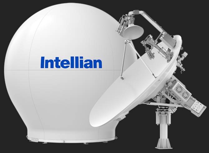
Intellian v240MT
v240MT unverified
Type
VSAT
Stabilized
ja
Common Failures & Inspection Points
  • Antenna obstruction, tracking fault or damaged radome causes loss of satellite lock, poor signal quality or repeated connection drops
  • Modem, terminal or network-interface failure causes unavailable data or voice services despite normal ship power
  • Power-supply or UPS faults cause terminal rebooting, blank displays or complete service loss
  • Cabling, connector or Ethernet faults cause intermittent connectivity or loss of interfaces to ship systems
  • Configuration, registration or service-provider problems prevent log-in or message transfer even when hardware tests appear normal
Service: Inspect antenna or radome, mounting, cabling, indoor units, power supply and network interfaces. Review signal-quality and terminal logs for recurring dropouts. Confirm vessel identity, service configuration and emergency functions where applicable. Antenna alignment, software and network settings should only be changed using approved documentation.
Spare Parts: Carry fuses, power supplies where supported, network and RF cables, connectors, approved modem or terminal modules where vessel policy requires them and backed-up configuration information.
Use Cases: Ocean-going merchant, passenger and offshore vessels requiring long-range safety, operational or crew communications.
v45C unverified
Stabilized
ja
Common Failures & Inspection Points
  • Antenna obstruction, tracking fault or damaged radome causes loss of satellite lock, poor signal quality or repeated connection drops
  • Modem, terminal or network-interface failure causes unavailable data or voice services despite normal ship power
  • Power-supply or UPS faults cause terminal rebooting, blank displays or complete service loss
  • Cabling, connector or Ethernet faults cause intermittent connectivity or loss of interfaces to ship systems
  • Configuration, registration or service-provider problems prevent log-in or message transfer even when hardware tests appear normal
Service: Inspect antenna or radome, mounting, cabling, indoor units, power supply and network interfaces. Review signal-quality and terminal logs for recurring dropouts. Confirm vessel identity, service configuration and emergency functions where applicable. Antenna alignment, software and network settings should only be changed using approved documentation.
Spare Parts: Carry fuses, power supplies where supported, network and RF cables, connectors, approved modem or terminal modules where vessel policy requires them and backed-up configuration information.
Use Cases: Ocean-going merchant, passenger and offshore vessels requiring long-range safety, operational or crew communications.
v85NX Mk2 unverified
Stabilized
ja
Common Failures & Inspection Points
  • Antenna obstruction, tracking fault or damaged radome causes loss of satellite lock, poor signal quality or repeated connection drops
  • Modem, terminal or network-interface failure causes unavailable data or voice services despite normal ship power
  • Power-supply or UPS faults cause terminal rebooting, blank displays or complete service loss
  • Cabling, connector or Ethernet faults cause intermittent connectivity or loss of interfaces to ship systems
  • Configuration, registration or service-provider problems prevent log-in or message transfer even when hardware tests appear normal
Service: Inspect antenna or radome, mounting, cabling, indoor units, power supply and network interfaces. Review signal-quality and terminal logs for recurring dropouts. Confirm vessel identity, service configuration and emergency functions where applicable. Antenna alignment, software and network settings should only be changed using approved documentation.
Spare Parts: Carry fuses, power supplies where supported, network and RF cables, connectors, approved modem or terminal modules where vessel policy requires them and backed-up configuration information.
Use Cases: Ocean-going merchant, passenger and offshore vessels requiring long-range safety, operational or crew communications.
v100Ka Mk2 unverified
Stabilized
ja
Common Failures & Inspection Points
  • Antenna obstruction, tracking fault or damaged radome causes loss of satellite lock, poor signal quality or repeated connection drops
  • Modem, terminal or network-interface failure causes unavailable data or voice services despite normal ship power
  • Power-supply or UPS faults cause terminal rebooting, blank displays or complete service loss
  • Cabling, connector or Ethernet faults cause intermittent connectivity or loss of interfaces to ship systems
  • Configuration, registration or service-provider problems prevent log-in or message transfer even when hardware tests appear normal
Service: Inspect antenna or radome, mounting, cabling, indoor units, power supply and network interfaces. Review signal-quality and terminal logs for recurring dropouts. Confirm vessel identity, service configuration and emergency functions where applicable. Antenna alignment, software and network settings should only be changed using approved documentation.
Spare Parts: Carry fuses, power supplies where supported, network and RF cables, connectors, approved modem or terminal modules where vessel policy requires them and backed-up configuration information.
Use Cases: Ocean-going merchant, passenger and offshore vessels requiring long-range safety, operational or crew communications.
v130G Mk2 unverified
Stabilized
ja
Common Failures & Inspection Points
  • Antenna obstruction, tracking fault or damaged radome causes loss of satellite lock, poor signal quality or repeated connection drops
  • Modem, terminal or network-interface failure causes unavailable data or voice services despite normal ship power
  • Power-supply or UPS faults cause terminal rebooting, blank displays or complete service loss
  • Cabling, connector or Ethernet faults cause intermittent connectivity or loss of interfaces to ship systems
  • Configuration, registration or service-provider problems prevent log-in or message transfer even when hardware tests appear normal
Service: Inspect antenna or radome, mounting, cabling, indoor units, power supply and network interfaces. Review signal-quality and terminal logs for recurring dropouts. Confirm vessel identity, service configuration and emergency functions where applicable. Antenna alignment, software and network settings should only be changed using approved documentation.
Spare Parts: Carry fuses, power supplies where supported, network and RF cables, connectors, approved modem or terminal modules where vessel policy requires them and backed-up configuration information.
Use Cases: Ocean-going merchant, passenger and offshore vessels requiring long-range safety, operational or crew communications.
v240M Mk2 unverified
Stabilized
ja
Common Failures & Inspection Points
  • Antenna obstruction, tracking fault or damaged radome causes loss of satellite lock, poor signal quality or repeated connection drops
  • Modem, terminal or network-interface failure causes unavailable data or voice services despite normal ship power
  • Power-supply or UPS faults cause terminal rebooting, blank displays or complete service loss
  • Cabling, connector or Ethernet faults cause intermittent connectivity or loss of interfaces to ship systems
  • Configuration, registration or service-provider problems prevent log-in or message transfer even when hardware tests appear normal
Service: Inspect antenna or radome, mounting, cabling, indoor units, power supply and network interfaces. Review signal-quality and terminal logs for recurring dropouts. Confirm vessel identity, service configuration and emergency functions where applicable. Antenna alignment, software and network settings should only be changed using approved documentation.
Spare Parts: Carry fuses, power supplies where supported, network and RF cables, connectors, approved modem or terminal modules where vessel policy requires them and backed-up configuration information.
Use Cases: Ocean-going merchant, passenger and offshore vessels requiring long-range safety, operational or crew communications.
GX100NX unverified
Stabilized
ja
Common Failures & Inspection Points
  • Antenna obstruction, tracking fault or damaged radome causes loss of satellite lock, poor signal quality or repeated connection drops
  • Modem, terminal or network-interface failure causes unavailable data or voice services despite normal ship power
  • Power-supply or UPS faults cause terminal rebooting, blank displays or complete service loss
  • Cabling, connector or Ethernet faults cause intermittent connectivity or loss of interfaces to ship systems
  • Configuration, registration or service-provider problems prevent log-in or message transfer even when hardware tests appear normal
Service: Inspect antenna or radome, mounting, cabling, indoor units, power supply and network interfaces. Review signal-quality and terminal logs for recurring dropouts. Confirm vessel identity, service configuration and emergency functions where applicable. Antenna alignment, software and network settings should only be changed using approved documentation.
Spare Parts: Carry fuses, power supplies where supported, network and RF cables, connectors, approved modem or terminal modules where vessel policy requires them and backed-up configuration information.
Use Cases: Ocean-going merchant, passenger and offshore vessels requiring long-range safety, operational or crew communications.
Intellian VSAT Ku-Band 37cm-C unverified
Antenna diameter cm
37
Band
Ku-Band
Stabilized
ja
Common Failures & Inspection Points
  • Loss of supply power from a tripped breaker, failed power unit, loose connection, or depleted reserve battery causes a dead unit, rebooting, or failure to transmit
  • Antenna, feeder, connector, or matching fault caused by corrosion, water ingress, or physical damage results in poor range, failed transmission, or weak received signals
  • Control-panel, display, keypad, or software faults can prevent channel selection, message handling, or normal operator input
  • Interface or position-data failure caused by wiring, configuration, or sensor faults can remove position information or connected-system data
  • Internal transmitter, receiver, or modem faults caused by component ageing or overheating can produce intermittent communication, alarms, or inability to establish a link
Service: Verify primary and reserve power, antenna and feeder condition, distress and safety functions permitted for routine testing, interfaces, audio quality, time and position inputs, and logged self-test results. Any regulatory test or adjustment must follow the vessel's radio procedures and manufacturer documentation.
Spare Parts: Carry the model-specific fuses, approved power-supply items, handset or microphone accessories, connector and sealing items, and critical interface or antenna components recommended by the manufacturer and vessel radio-maintenance plan.
Use Cases: Used on SOLAS merchant ships, offshore vessels, passenger ships, fishing vessels, workboats, and other craft requiring marine radio, distress, safety, or navigation communications.
Intellian VSAT Ka-Band 37cm-C unverified
Antenna diameter cm
37
Band
Ka-Band
Stabilized
ja
Common Failures & Inspection Points
  • Loss of supply power from a tripped breaker, failed power unit, loose connection, or depleted reserve battery causes a dead unit, rebooting, or failure to transmit
  • Antenna, feeder, connector, or matching fault caused by corrosion, water ingress, or physical damage results in poor range, failed transmission, or weak received signals
  • Control-panel, display, keypad, or software faults can prevent channel selection, message handling, or normal operator input
  • Interface or position-data failure caused by wiring, configuration, or sensor faults can remove position information or connected-system data
  • Internal transmitter, receiver, or modem faults caused by component ageing or overheating can produce intermittent communication, alarms, or inability to establish a link
Service: Verify primary and reserve power, antenna and feeder condition, distress and safety functions permitted for routine testing, interfaces, audio quality, time and position inputs, and logged self-test results. Any regulatory test or adjustment must follow the vessel's radio procedures and manufacturer documentation.
Spare Parts: Carry the model-specific fuses, approved power-supply items, handset or microphone accessories, connector and sealing items, and critical interface or antenna components recommended by the manufacturer and vessel radio-maintenance plan.
Use Cases: Used on SOLAS merchant ships, offshore vessels, passenger ships, fishing vessels, workboats, and other craft requiring marine radio, distress, safety, or navigation communications.
Intellian VSAT Ku-Band 45cm-C unverified
Antenna diameter cm
45
Band
Ku-Band
Stabilized
ja
Common Failures & Inspection Points
  • Loss of supply power from a tripped breaker, failed power unit, loose connection, or depleted reserve battery causes a dead unit, rebooting, or failure to transmit
  • Antenna, feeder, connector, or matching fault caused by corrosion, water ingress, or physical damage results in poor range, failed transmission, or weak received signals
  • Control-panel, display, keypad, or software faults can prevent channel selection, message handling, or normal operator input
  • Interface or position-data failure caused by wiring, configuration, or sensor faults can remove position information or connected-system data
  • Internal transmitter, receiver, or modem faults caused by component ageing or overheating can produce intermittent communication, alarms, or inability to establish a link
Service: Verify primary and reserve power, antenna and feeder condition, distress and safety functions permitted for routine testing, interfaces, audio quality, time and position inputs, and logged self-test results. Any regulatory test or adjustment must follow the vessel's radio procedures and manufacturer documentation.
Spare Parts: Carry the model-specific fuses, approved power-supply items, handset or microphone accessories, connector and sealing items, and critical interface or antenna components recommended by the manufacturer and vessel radio-maintenance plan.
Use Cases: Used on SOLAS merchant ships, offshore vessels, passenger ships, fishing vessels, workboats, and other craft requiring marine radio, distress, safety, or navigation communications.
Intellian VSAT Ka-Band 45cm-C unverified
Antenna diameter cm
45
Band
Ka-Band
Stabilized
ja
Common Failures & Inspection Points
  • Loss of supply power from a tripped breaker, failed power unit, loose connection, or depleted reserve battery causes a dead unit, rebooting, or failure to transmit
  • Antenna, feeder, connector, or matching fault caused by corrosion, water ingress, or physical damage results in poor range, failed transmission, or weak received signals
  • Control-panel, display, keypad, or software faults can prevent channel selection, message handling, or normal operator input
  • Interface or position-data failure caused by wiring, configuration, or sensor faults can remove position information or connected-system data
  • Internal transmitter, receiver, or modem faults caused by component ageing or overheating can produce intermittent communication, alarms, or inability to establish a link
Service: Verify primary and reserve power, antenna and feeder condition, distress and safety functions permitted for routine testing, interfaces, audio quality, time and position inputs, and logged self-test results. Any regulatory test or adjustment must follow the vessel's radio procedures and manufacturer documentation.
Spare Parts: Carry the model-specific fuses, approved power-supply items, handset or microphone accessories, connector and sealing items, and critical interface or antenna components recommended by the manufacturer and vessel radio-maintenance plan.
Use Cases: Used on SOLAS merchant ships, offshore vessels, passenger ships, fishing vessels, workboats, and other craft requiring marine radio, distress, safety, or navigation communications.
Intellian VSAT Ku-Band 60cm-C unverified
Antenna diameter cm
60
Band
Ku-Band
Stabilized
ja
Common Failures & Inspection Points
  • Loss of supply power from a tripped breaker, failed power unit, loose connection, or depleted reserve battery causes a dead unit, rebooting, or failure to transmit
  • Antenna, feeder, connector, or matching fault caused by corrosion, water ingress, or physical damage results in poor range, failed transmission, or weak received signals
  • Control-panel, display, keypad, or software faults can prevent channel selection, message handling, or normal operator input
  • Interface or position-data failure caused by wiring, configuration, or sensor faults can remove position information or connected-system data
  • Internal transmitter, receiver, or modem faults caused by component ageing or overheating can produce intermittent communication, alarms, or inability to establish a link
Service: Verify primary and reserve power, antenna and feeder condition, distress and safety functions permitted for routine testing, interfaces, audio quality, time and position inputs, and logged self-test results. Any regulatory test or adjustment must follow the vessel's radio procedures and manufacturer documentation.
Spare Parts: Carry the model-specific fuses, approved power-supply items, handset or microphone accessories, connector and sealing items, and critical interface or antenna components recommended by the manufacturer and vessel radio-maintenance plan.
Use Cases: Used on SOLAS merchant ships, offshore vessels, passenger ships, fishing vessels, workboats, and other craft requiring marine radio, distress, safety, or navigation communications.
Intellian VSAT Ka-Band 60cm-C unverified
Antenna diameter cm
60
Band
Ka-Band
Stabilized
ja
Common Failures & Inspection Points
  • Loss of supply power from a tripped breaker, failed power unit, loose connection, or depleted reserve battery causes a dead unit, rebooting, or failure to transmit
  • Antenna, feeder, connector, or matching fault caused by corrosion, water ingress, or physical damage results in poor range, failed transmission, or weak received signals
  • Control-panel, display, keypad, or software faults can prevent channel selection, message handling, or normal operator input
  • Interface or position-data failure caused by wiring, configuration, or sensor faults can remove position information or connected-system data
  • Internal transmitter, receiver, or modem faults caused by component ageing or overheating can produce intermittent communication, alarms, or inability to establish a link
Service: Verify primary and reserve power, antenna and feeder condition, distress and safety functions permitted for routine testing, interfaces, audio quality, time and position inputs, and logged self-test results. Any regulatory test or adjustment must follow the vessel's radio procedures and manufacturer documentation.
Spare Parts: Carry the model-specific fuses, approved power-supply items, handset or microphone accessories, connector and sealing items, and critical interface or antenna components recommended by the manufacturer and vessel radio-maintenance plan.
Use Cases: Used on SOLAS merchant ships, offshore vessels, passenger ships, fishing vessels, workboats, and other craft requiring marine radio, distress, safety, or navigation communications.
Intellian VSAT Ku-Band 85cm-C unverified
Antenna diameter cm
85
Band
Ku-Band
Stabilized
ja
Common Failures & Inspection Points
  • Loss of supply power from a tripped breaker, failed power unit, loose connection, or depleted reserve battery causes a dead unit, rebooting, or failure to transmit
  • Antenna, feeder, connector, or matching fault caused by corrosion, water ingress, or physical damage results in poor range, failed transmission, or weak received signals
  • Control-panel, display, keypad, or software faults can prevent channel selection, message handling, or normal operator input
  • Interface or position-data failure caused by wiring, configuration, or sensor faults can remove position information or connected-system data
  • Internal transmitter, receiver, or modem faults caused by component ageing or overheating can produce intermittent communication, alarms, or inability to establish a link
Service: Verify primary and reserve power, antenna and feeder condition, distress and safety functions permitted for routine testing, interfaces, audio quality, time and position inputs, and logged self-test results. Any regulatory test or adjustment must follow the vessel's radio procedures and manufacturer documentation.
Spare Parts: Carry the model-specific fuses, approved power-supply items, handset or microphone accessories, connector and sealing items, and critical interface or antenna components recommended by the manufacturer and vessel radio-maintenance plan.
Use Cases: Used on SOLAS merchant ships, offshore vessels, passenger ships, fishing vessels, workboats, and other craft requiring marine radio, distress, safety, or navigation communications.
Intellian VSAT Ka-Band 85cm-C unverified
Antenna diameter cm
85
Band
Ka-Band
Stabilized
ja
Common Failures & Inspection Points
  • Loss of supply power from a tripped breaker, failed power unit, loose connection, or depleted reserve battery causes a dead unit, rebooting, or failure to transmit
  • Antenna, feeder, connector, or matching fault caused by corrosion, water ingress, or physical damage results in poor range, failed transmission, or weak received signals
  • Control-panel, display, keypad, or software faults can prevent channel selection, message handling, or normal operator input
  • Interface or position-data failure caused by wiring, configuration, or sensor faults can remove position information or connected-system data
  • Internal transmitter, receiver, or modem faults caused by component ageing or overheating can produce intermittent communication, alarms, or inability to establish a link
Service: Verify primary and reserve power, antenna and feeder condition, distress and safety functions permitted for routine testing, interfaces, audio quality, time and position inputs, and logged self-test results. Any regulatory test or adjustment must follow the vessel's radio procedures and manufacturer documentation.
Spare Parts: Carry the model-specific fuses, approved power-supply items, handset or microphone accessories, connector and sealing items, and critical interface or antenna components recommended by the manufacturer and vessel radio-maintenance plan.
Use Cases: Used on SOLAS merchant ships, offshore vessels, passenger ships, fishing vessels, workboats, and other craft requiring marine radio, distress, safety, or navigation communications.
Intellian VSAT Ku-Band 100cm-C unverified
Antenna diameter cm
100
Band
Ku-Band
Stabilized
ja
Common Failures & Inspection Points
  • Loss of supply power from a tripped breaker, failed power unit, loose connection, or depleted reserve battery causes a dead unit, rebooting, or failure to transmit
  • Antenna, feeder, connector, or matching fault caused by corrosion, water ingress, or physical damage results in poor range, failed transmission, or weak received signals
  • Control-panel, display, keypad, or software faults can prevent channel selection, message handling, or normal operator input
  • Interface or position-data failure caused by wiring, configuration, or sensor faults can remove position information or connected-system data
  • Internal transmitter, receiver, or modem faults caused by component ageing or overheating can produce intermittent communication, alarms, or inability to establish a link
Service: Verify primary and reserve power, antenna and feeder condition, distress and safety functions permitted for routine testing, interfaces, audio quality, time and position inputs, and logged self-test results. Any regulatory test or adjustment must follow the vessel's radio procedures and manufacturer documentation.
Spare Parts: Carry the model-specific fuses, approved power-supply items, handset or microphone accessories, connector and sealing items, and critical interface or antenna components recommended by the manufacturer and vessel radio-maintenance plan.
Use Cases: Used on SOLAS merchant ships, offshore vessels, passenger ships, fishing vessels, workboats, and other craft requiring marine radio, distress, safety, or navigation communications.
Intellian VSAT Ka-Band 100cm-C unverified
Antenna diameter cm
100
Band
Ka-Band
Stabilized
ja
Common Failures & Inspection Points
  • Loss of supply power from a tripped breaker, failed power unit, loose connection, or depleted reserve battery causes a dead unit, rebooting, or failure to transmit
  • Antenna, feeder, connector, or matching fault caused by corrosion, water ingress, or physical damage results in poor range, failed transmission, or weak received signals
  • Control-panel, display, keypad, or software faults can prevent channel selection, message handling, or normal operator input
  • Interface or position-data failure caused by wiring, configuration, or sensor faults can remove position information or connected-system data
  • Internal transmitter, receiver, or modem faults caused by component ageing or overheating can produce intermittent communication, alarms, or inability to establish a link
Service: Verify primary and reserve power, antenna and feeder condition, distress and safety functions permitted for routine testing, interfaces, audio quality, time and position inputs, and logged self-test results. Any regulatory test or adjustment must follow the vessel's radio procedures and manufacturer documentation.
Spare Parts: Carry the model-specific fuses, approved power-supply items, handset or microphone accessories, connector and sealing items, and critical interface or antenna components recommended by the manufacturer and vessel radio-maintenance plan.
Use Cases: Used on SOLAS merchant ships, offshore vessels, passenger ships, fishing vessels, workboats, and other craft requiring marine radio, distress, safety, or navigation communications.
Intellian VSAT C-Band 100cm-C unverified
Antenna diameter cm
100
Band
C-Band
Stabilized
ja
Common Failures & Inspection Points
  • Loss of supply power from a tripped breaker, failed power unit, loose connection, or depleted reserve battery causes a dead unit, rebooting, or failure to transmit
  • Antenna, feeder, connector, or matching fault caused by corrosion, water ingress, or physical damage results in poor range, failed transmission, or weak received signals
  • Control-panel, display, keypad, or software faults can prevent channel selection, message handling, or normal operator input
  • Interface or position-data failure caused by wiring, configuration, or sensor faults can remove position information or connected-system data
  • Internal transmitter, receiver, or modem faults caused by component ageing or overheating can produce intermittent communication, alarms, or inability to establish a link
Service: Verify primary and reserve power, antenna and feeder condition, distress and safety functions permitted for routine testing, interfaces, audio quality, time and position inputs, and logged self-test results. Any regulatory test or adjustment must follow the vessel's radio procedures and manufacturer documentation.
Spare Parts: Carry the model-specific fuses, approved power-supply items, handset or microphone accessories, connector and sealing items, and critical interface or antenna components recommended by the manufacturer and vessel radio-maintenance plan.
Use Cases: Used on SOLAS merchant ships, offshore vessels, passenger ships, fishing vessels, workboats, and other craft requiring marine radio, distress, safety, or navigation communications.
Intellian VSAT Ku-Band 130cm-C unverified
Antenna diameter cm
130
Band
Ku-Band
Stabilized
ja
Common Failures & Inspection Points
  • Loss of supply power from a tripped breaker, failed power unit, loose connection, or depleted reserve battery causes a dead unit, rebooting, or failure to transmit
  • Antenna, feeder, connector, or matching fault caused by corrosion, water ingress, or physical damage results in poor range, failed transmission, or weak received signals
  • Control-panel, display, keypad, or software faults can prevent channel selection, message handling, or normal operator input
  • Interface or position-data failure caused by wiring, configuration, or sensor faults can remove position information or connected-system data
  • Internal transmitter, receiver, or modem faults caused by component ageing or overheating can produce intermittent communication, alarms, or inability to establish a link
Service: Verify primary and reserve power, antenna and feeder condition, distress and safety functions permitted for routine testing, interfaces, audio quality, time and position inputs, and logged self-test results. Any regulatory test or adjustment must follow the vessel's radio procedures and manufacturer documentation.
Spare Parts: Carry the model-specific fuses, approved power-supply items, handset or microphone accessories, connector and sealing items, and critical interface or antenna components recommended by the manufacturer and vessel radio-maintenance plan.
Use Cases: Used on SOLAS merchant ships, offshore vessels, passenger ships, fishing vessels, workboats, and other craft requiring marine radio, distress, safety, or navigation communications.
Intellian VSAT Ka-Band 130cm-C unverified
Antenna diameter cm
130
Band
Ka-Band
Stabilized
ja
Intellian VSAT C-Band 130cm-C unverified
Antenna diameter cm
130
Band
C-Band
Stabilized
ja
Common Failures & Inspection Points
  • Loss of supply power from a tripped breaker, failed power unit, loose connection, or depleted reserve battery causes a dead unit, rebooting, or failure to transmit
  • Antenna, feeder, connector, or matching fault caused by corrosion, water ingress, or physical damage results in poor range, failed transmission, or weak received signals
  • Control-panel, display, keypad, or software faults can prevent channel selection, message handling, or normal operator input
  • Interface or position-data failure caused by wiring, configuration, or sensor faults can remove position information or connected-system data
  • Internal transmitter, receiver, or modem faults caused by component ageing or overheating can produce intermittent communication, alarms, or inability to establish a link
Service: Verify primary and reserve power, antenna and feeder condition, distress and safety functions permitted for routine testing, interfaces, audio quality, time and position inputs, and logged self-test results. Any regulatory test or adjustment must follow the vessel's radio procedures and manufacturer documentation.
Spare Parts: Carry the model-specific fuses, approved power-supply items, handset or microphone accessories, connector and sealing items, and critical interface or antenna components recommended by the manufacturer and vessel radio-maintenance plan.
Use Cases: Used on SOLAS merchant ships, offshore vessels, passenger ships, fishing vessels, workboats, and other craft requiring marine radio, distress, safety, or navigation communications.
Intellian VSAT Ku-Band 240cm-C unverified
Antenna diameter cm
240
Band
Ku-Band
Stabilized
ja
Common Failures & Inspection Points
  • Loss of supply power from a tripped breaker, failed power unit, loose connection, or depleted reserve battery causes a dead unit, rebooting, or failure to transmit
  • Antenna, feeder, connector, or matching fault caused by corrosion, water ingress, or physical damage results in poor range, failed transmission, or weak received signals
  • Control-panel, display, keypad, or software faults can prevent channel selection, message handling, or normal operator input
  • Interface or position-data failure caused by wiring, configuration, or sensor faults can remove position information or connected-system data
  • Internal transmitter, receiver, or modem faults caused by component ageing or overheating can produce intermittent communication, alarms, or inability to establish a link
Service: Verify primary and reserve power, antenna and feeder condition, distress and safety functions permitted for routine testing, interfaces, audio quality, time and position inputs, and logged self-test results. Any regulatory test or adjustment must follow the vessel's radio procedures and manufacturer documentation.
Spare Parts: Carry the model-specific fuses, approved power-supply items, handset or microphone accessories, connector and sealing items, and critical interface or antenna components recommended by the manufacturer and vessel radio-maintenance plan.
Use Cases: Used on SOLAS merchant ships, offshore vessels, passenger ships, fishing vessels, workboats, and other craft requiring marine radio, distress, safety, or navigation communications.
Intellian VSAT Ka-Band 240cm-C unverified
Antenna diameter cm
240
Band
Ka-Band
Stabilized
ja
Common Failures & Inspection Points
  • Loss of supply power from a tripped breaker, failed power unit, loose connection, or depleted reserve battery causes a dead unit, rebooting, or failure to transmit
  • Antenna, feeder, connector, or matching fault caused by corrosion, water ingress, or physical damage results in poor range, failed transmission, or weak received signals
  • Control-panel, display, keypad, or software faults can prevent channel selection, message handling, or normal operator input
  • Interface or position-data failure caused by wiring, configuration, or sensor faults can remove position information or connected-system data
  • Internal transmitter, receiver, or modem faults caused by component ageing or overheating can produce intermittent communication, alarms, or inability to establish a link
Service: Verify primary and reserve power, antenna and feeder condition, distress and safety functions permitted for routine testing, interfaces, audio quality, time and position inputs, and logged self-test results. Any regulatory test or adjustment must follow the vessel's radio procedures and manufacturer documentation.
Spare Parts: Carry the model-specific fuses, approved power-supply items, handset or microphone accessories, connector and sealing items, and critical interface or antenna components recommended by the manufacturer and vessel radio-maintenance plan.
Use Cases: Used on SOLAS merchant ships, offshore vessels, passenger ships, fishing vessels, workboats, and other craft requiring marine radio, distress, safety, or navigation communications.
Intellian VSAT C-Band 240cm-C unverified
Antenna diameter cm
240
Band
C-Band
Stabilized
ja
Common Failures & Inspection Points
  • Loss of supply power from a tripped breaker, failed power unit, loose connection, or depleted reserve battery causes a dead unit, rebooting, or failure to transmit
  • Antenna, feeder, connector, or matching fault caused by corrosion, water ingress, or physical damage results in poor range, failed transmission, or weak received signals
  • Control-panel, display, keypad, or software faults can prevent channel selection, message handling, or normal operator input
  • Interface or position-data failure caused by wiring, configuration, or sensor faults can remove position information or connected-system data
  • Internal transmitter, receiver, or modem faults caused by component ageing or overheating can produce intermittent communication, alarms, or inability to establish a link
Service: Verify primary and reserve power, antenna and feeder condition, distress and safety functions permitted for routine testing, interfaces, audio quality, time and position inputs, and logged self-test results. Any regulatory test or adjustment must follow the vessel's radio procedures and manufacturer documentation.
Spare Parts: Carry the model-specific fuses, approved power-supply items, handset or microphone accessories, connector and sealing items, and critical interface or antenna components recommended by the manufacturer and vessel radio-maintenance plan.
Use Cases: Used on SOLAS merchant ships, offshore vessels, passenger ships, fishing vessels, workboats, and other craft requiring marine radio, distress, safety, or navigation communications.

KVH Industries

26
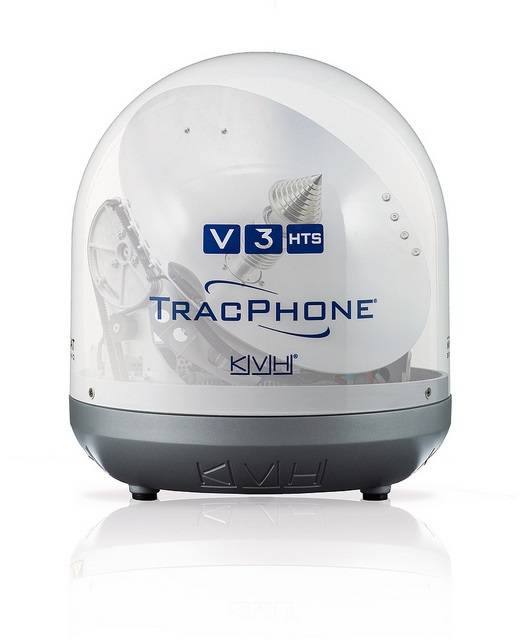
KVH Industries TracPhone V3-HTS
TracPhone V3-HTS unverified
Type
mini-VSAT
Stabilized
ja
Common Failures & Inspection Points
  • Antenna, feeder or tuning fault caused by corrosion, damaged cabling or poor connections, resulting in weak transmission, reception problems or equipment alarms
  • Power-supply or backup-battery failure caused by charger defects, aged batteries or wiring faults, resulting in loss of availability when main power is removed
  • Transmitter or receiver failure caused by RF-component or electronic faults, resulting in inability to establish communications or receive expected traffic
  • Position or time-input failure caused by GNSS or network faults, resulting in missing or incorrect data in distress or DSC functions
  • Control, display or software fault caused by hardware failure or configuration problems, resulting in frozen controls, error messages or unavailable functions
Service: Perform operational and self-tests permitted by the vessel's procedures without generating unintended distress alerts. Inspect antennas, feeders, grounding, power supplies, backup batteries and connected navigation-data inputs. Verify station identity, position input, time and configured communication services against approved records. Check printers, handsets, microphones and alarm interfaces where fitted. Maintain software, licenses and service subscriptions required by the installed system. Refer to manufacturer and regulatory documentation for exact test methods, battery criteria and approved servicing.
Spare Parts: Keep fuses, handset or microphone accessories, printer consumables where applicable, selected power-supply components and manufacturer-recommended electronic spares. Antenna or feeder repair materials and backup-battery arrangements should reflect the vessel's redundancy plan. Preserve type approval and programmed identity when replacing core units.
Use Cases: Distress, urgency, safety and routine maritime communications within the vessel's GMDSS and operational communications fit.
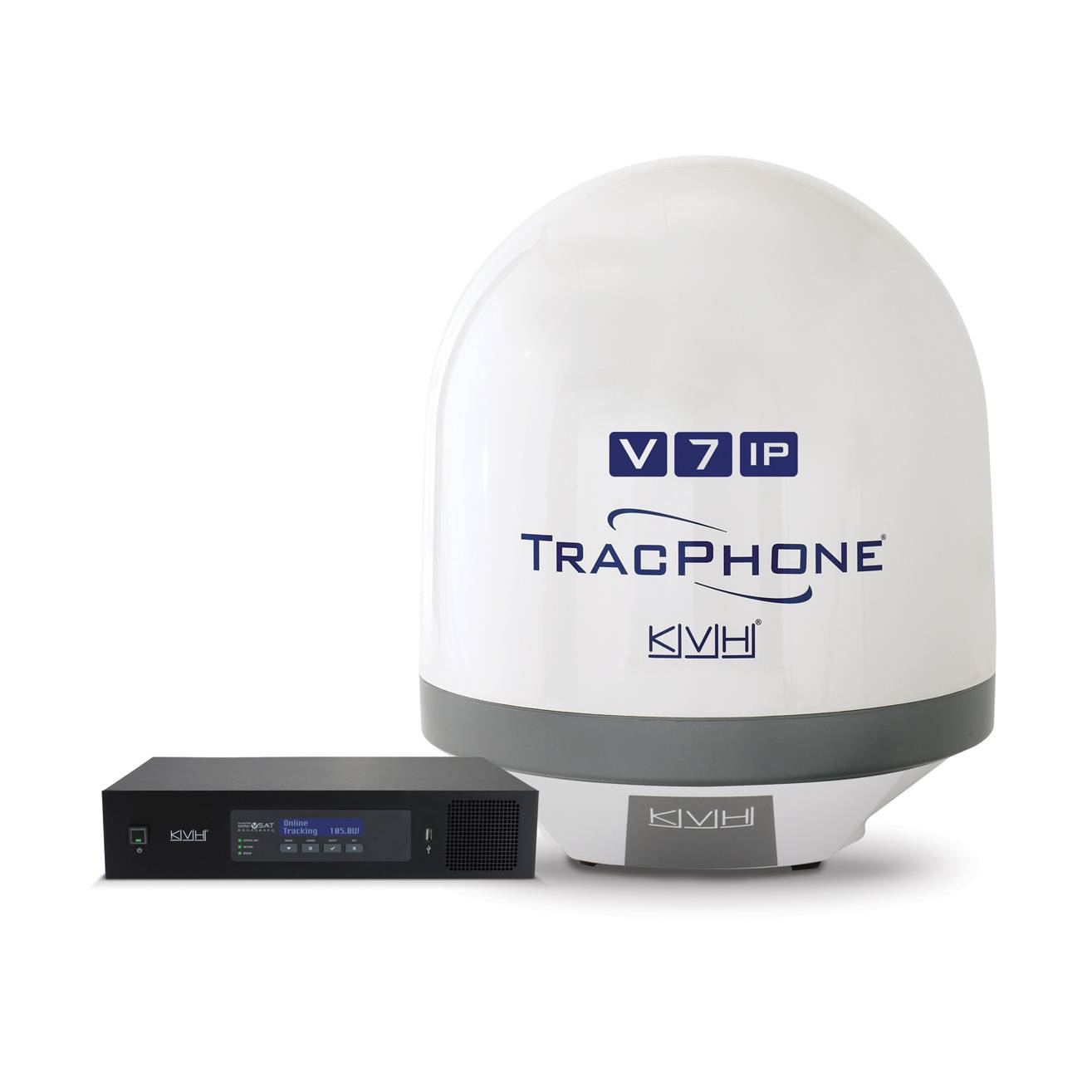
KVH Industries TracPhone V7-HTS
TracPhone V7-HTS unverified
Type
mini-VSAT
Stabilized
ja
Common Failures & Inspection Points
  • Antenna, feeder or tuning fault caused by corrosion, damaged cabling or poor connections, resulting in weak transmission, reception problems or equipment alarms
  • Power-supply or backup-battery failure caused by charger defects, aged batteries or wiring faults, resulting in loss of availability when main power is removed
  • Transmitter or receiver failure caused by RF-component or electronic faults, resulting in inability to establish communications or receive expected traffic
  • Position or time-input failure caused by GNSS or network faults, resulting in missing or incorrect data in distress or DSC functions
  • Control, display or software fault caused by hardware failure or configuration problems, resulting in frozen controls, error messages or unavailable functions
Service: Perform operational and self-tests permitted by the vessel's procedures without generating unintended distress alerts. Inspect antennas, feeders, grounding, power supplies, backup batteries and connected navigation-data inputs. Verify station identity, position input, time and configured communication services against approved records. Check printers, handsets, microphones and alarm interfaces where fitted. Maintain software, licenses and service subscriptions required by the installed system. Refer to manufacturer and regulatory documentation for exact test methods, battery criteria and approved servicing.
Spare Parts: Keep fuses, handset or microphone accessories, printer consumables where applicable, selected power-supply components and manufacturer-recommended electronic spares. Antenna or feeder repair materials and backup-battery arrangements should reflect the vessel's redundancy plan. Preserve type approval and programmed identity when replacing core units.
Use Cases: Distress, urgency, safety and routine maritime communications within the vessel's GMDSS and operational communications fit.
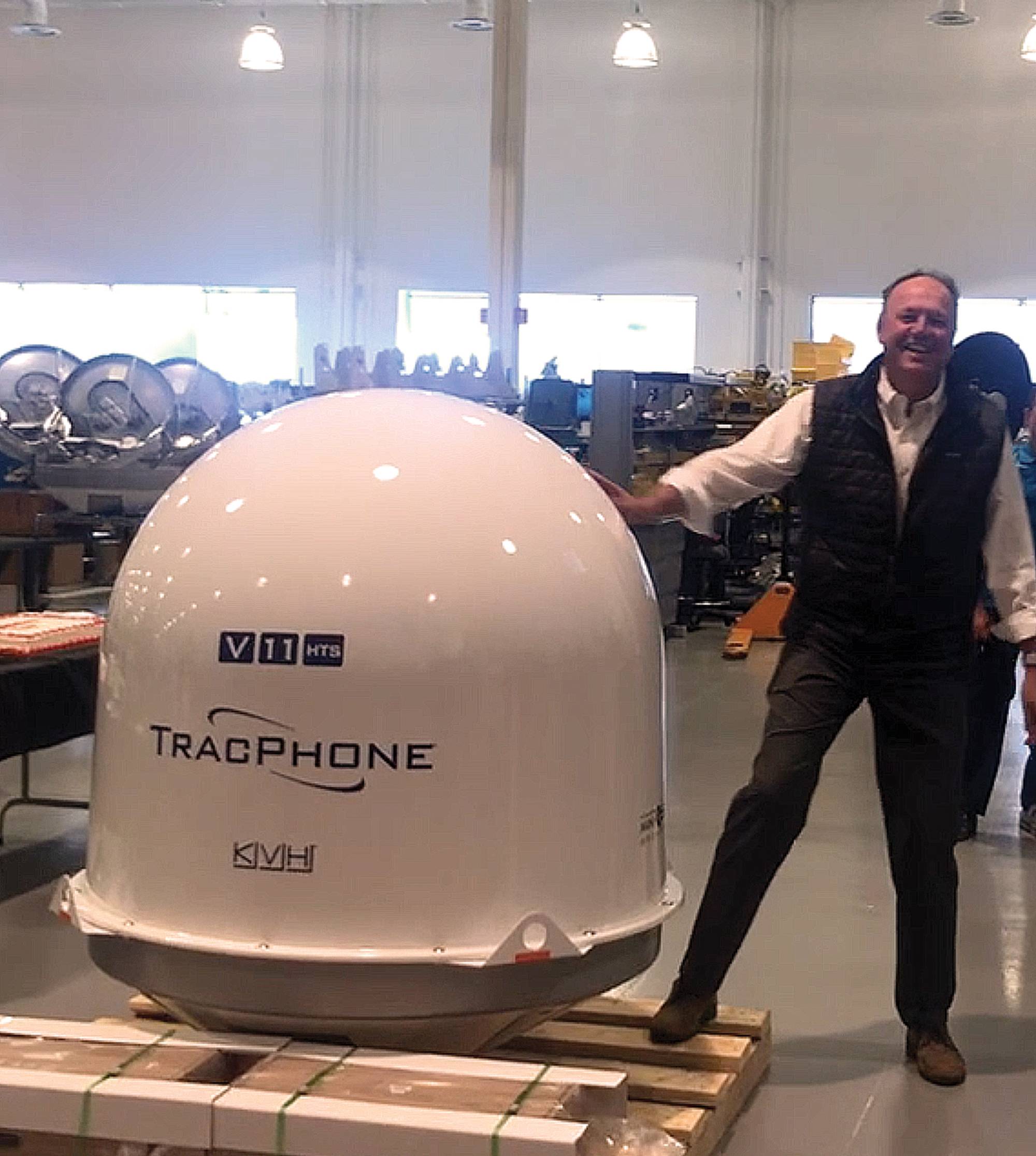
TracPhone V11-HTS unverified
Type
mini-VSAT
Stabilized
ja
Common Failures & Inspection Points
  • Antenna obstruction, tracking fault or damaged radome causes loss of satellite lock or repeated connection drops
  • Terminal, modem or network-interface faults cause unavailable data or voice service despite normal ship power
  • Power-supply or UPS faults cause terminal rebooting or complete service loss
  • Cabling or connector faults cause intermittent connectivity or loss of interfaces to ship systems
  • Configuration, registration or service-provider problems prevent log-in or message transfer even when hardware appears normal
Service: Inspect antenna or radome, mounting, cabling, indoor units, power supply and network interfaces. Review signal quality and terminal logs for recurring dropouts. Confirm vessel identity and service configuration. Antenna alignment, software and network changes should follow approved documentation.
Spare Parts: Carry fuses, power supplies where supported, RF and network cables, connectors, approved modem or terminal modules and backed-up configuration information.
Use Cases: Ocean-going merchant, passenger and offshore vessels requiring long-range safety and operational communications.
TracPhone V30 unverified
Type
mini-VSAT
Stabilized
ja
Common Failures & Inspection Points
  • Loss of supply power from a tripped breaker, failed power unit, loose connection, or depleted reserve battery causes a dead unit, rebooting, or failure to transmit
  • Antenna, feeder, connector, or matching fault caused by corrosion, water ingress, or physical damage results in poor range, failed transmission, or weak received signals
  • Control-panel, display, keypad, or software faults can prevent channel selection, message handling, or normal operator input
  • Interface or position-data failure caused by wiring, configuration, or sensor faults can remove position information or connected-system data
  • Internal transmitter, receiver, or modem faults caused by component ageing or overheating can produce intermittent communication, alarms, or inability to establish a link
Service: Verify primary and reserve power, antenna and feeder condition, distress and safety functions permitted for routine testing, interfaces, audio quality, time and position inputs, and logged self-test results. Any regulatory test or adjustment must follow the vessel's radio procedures and manufacturer documentation.
Spare Parts: Carry the model-specific fuses, approved power-supply items, handset or microphone accessories, connector and sealing items, and critical interface or antenna components recommended by the manufacturer and vessel radio-maintenance plan.
Use Cases: Used on SOLAS merchant ships, offshore vessels, passenger ships, fishing vessels, workboats, and other craft requiring marine radio, distress, safety, or navigation communications.
TracPhone V3-HTS Mk2 unverified
Stabilized
ja
Common Failures & Inspection Points
  • Antenna, feeder or connector corrosion causes weak reception, poor transmission or high reflected-power indications
  • Power-supply or backup-battery faults cause resets or loss of availability during main-power failure
  • GNSS or data-interface loss causes missing position or identity information in transmitted messages
  • Microphone, handset, speaker or operator-control faults impair communication despite the main unit remaining powered
  • Configuration or programming errors can cause incorrect identity, channel or service behaviour
Service: Carry out the approved self-tests and operational checks without generating false distress alerts. Inspect antennas, feeders, connectors, earth or bonding arrangements where applicable, reserve supply and interfaces to navigation data. Verify programmed identity information and GMDSS records; exact radio tests, power measurements and configuration procedures must follow manufacturer and statutory documentation.
Spare Parts: Keep approved fuses, handset or microphone parts, antenna connectors, selected cables, printer consumables where fitted and critical power-supply or interface modules according to the vessel's GMDSS spares arrangement.
Use Cases: Used on seagoing vessels for distress, safety and routine maritime communications as part of the bridge and GMDSS installation.
TracPhone V7-HTS Mk2 unverified
Stabilized
ja
Common Failures & Inspection Points
  • Antenna, feeder or connector corrosion causes weak reception, poor transmission or high reflected-power indications
  • Power-supply or backup-battery faults cause resets or loss of availability during main-power failure
  • GNSS or data-interface loss causes missing position or identity information in transmitted messages
  • Microphone, handset, speaker or operator-control faults impair communication despite the main unit remaining powered
  • Configuration or programming errors can cause incorrect identity, channel or service behaviour
Service: Carry out the approved self-tests and operational checks without generating false distress alerts. Inspect antennas, feeders, connectors, earth or bonding arrangements where applicable, reserve supply and interfaces to navigation data. Verify programmed identity information and GMDSS records; exact radio tests, power measurements and configuration procedures must follow manufacturer and statutory documentation.
Spare Parts: Keep approved fuses, handset or microphone parts, antenna connectors, selected cables, printer consumables where fitted and critical power-supply or interface modules according to the vessel's GMDSS spares arrangement.
Use Cases: Used on seagoing vessels for distress, safety and routine maritime communications as part of the bridge and GMDSS installation.
KVH Industries TracPhone V11-HTS Mk2
TracPhone V11-HTS Mk2 unverified
Stabilized
ja
Common Failures & Inspection Points
  • Antenna, feeder or tuning fault caused by corrosion, damaged cabling or poor connections, resulting in weak transmission, reception problems or equipment alarms
  • Power-supply or backup-battery failure caused by charger defects, aged batteries or wiring faults, resulting in loss of availability when normal power is removed
  • Transmitter or receiver failure caused by RF-component or electronic faults, resulting in inability to establish communications or receive expected traffic
  • Position, time or identity-input problem caused by navigation-data or configuration faults, resulting in missing or incorrect information in distress or DSC functions
  • Control, display or software fault caused by hardware failure or configuration problems, resulting in frozen controls, error messages or unavailable functions
Service: Perform operational and self-tests permitted by the vessel's procedures without generating unintended distress alerts. Inspect antennas, feeders, grounding, power supplies, backup batteries and connected navigation-data inputs. Verify programmed station identity, position input, time and configured communication services against approved records. Check handsets, microphones, printers and alarm interfaces where fitted. Maintain software, licenses and service subscriptions required by the installed system. Refer to manufacturer and regulatory documentation for exact test methods, battery criteria and approved servicing.
Spare Parts: Keep fuses, handset or microphone accessories, printer consumables where applicable, selected power-supply components and manufacturer-recommended electronic spares. Antenna or feeder repair materials and backup-battery arrangements should reflect the vessel's redundancy plan. Preserve type approval and programmed identity when replacing core units.
Use Cases: Distress, urgency, safety and routine maritime communications within the vessel's GMDSS and operational communications fit.
TracPhone LTE-1 unverified
Stabilized
ja
Common Failures & Inspection Points
  • Antenna, feeder or tuning fault caused by corrosion, damaged cabling or poor connections, resulting in weak transmission, reception problems or equipment alarms
  • Power-supply or backup-battery failure caused by charger defects, aged batteries or wiring faults, resulting in loss of availability when main power is removed
  • Transmitter or receiver failure caused by RF-component or electronic faults, resulting in inability to establish communications or receive expected traffic
  • Position or time-input failure caused by GNSS or network faults, resulting in missing or incorrect data in distress or DSC functions
  • Control, display or software fault caused by hardware failure or configuration problems, resulting in frozen controls, error messages or unavailable functions
Service: Perform operational and self-tests permitted by the vessel's procedures without generating unintended distress alerts. Inspect antennas, feeders, grounding, power supplies, backup batteries and connected navigation-data inputs. Verify station identity, position input, time and configured communication services against approved records. Check printers, handsets, microphones and alarm interfaces where fitted. Maintain software, licenses and service subscriptions required by the installed system. Refer to manufacturer and regulatory documentation for exact test methods, battery criteria and approved servicing.
Spare Parts: Keep fuses, handset or microphone accessories, printer consumables where applicable, selected power-supply components and manufacturer-recommended electronic spares. Antenna or feeder repair materials and backup-battery arrangements should reflect the vessel's redundancy plan. Preserve type approval and programmed identity when replacing core units.
Use Cases: Distress, urgency, safety and routine maritime communications within the vessel's GMDSS and operational communications fit.
HTS 50 unverified
Stabilized
ja
Common Failures & Inspection Points
  • Antenna obstruction, tracking fault or damaged radome causes loss of satellite lock, poor signal quality or repeated connection drops
  • Modem, terminal or network-interface failure causes unavailable data or voice services despite normal ship power
  • Power-supply or UPS faults cause terminal rebooting, blank displays or complete service loss
  • Cabling, connector or Ethernet faults cause intermittent connectivity or loss of interfaces to ship systems
  • Configuration, registration or service-provider problems prevent log-in or message transfer even when hardware tests appear normal
Service: Inspect antenna or radome, mounting, cabling, indoor units, power supply and network interfaces. Review signal-quality and terminal logs for recurring dropouts. Confirm vessel identity, service configuration and emergency functions where applicable. Antenna alignment, software and network settings should only be changed using approved documentation.
Spare Parts: Carry fuses, power supplies where supported, network and RF cables, connectors, approved modem or terminal modules where vessel policy requires them and backed-up configuration information.
Use Cases: Ocean-going merchant, passenger and offshore vessels requiring long-range safety, operational or crew communications.
KVH Industries VSAT Ku-Band 37cm-C unverified
Antenna diameter cm
37
Band
Ku-Band
Stabilized
ja
Common Failures & Inspection Points
  • Antenna or RF/cabling fault, typically indicated by loss of link, weak signal or communication alarm
  • Power-supply/reserve battery failure, typically indicated by terminal shutdown or reserve-power alarm
  • Terminal software/network fault, typically indicated by registration failure, frozen interface or loss of messaging
  • GNSS/time input fault where used, typically indicated by missing position in distress data or navigation-data alarm
  • Connector corrosion or water ingress, typically indicated by intermittent communication or high RF loss
Service: Check self-tests, distress controls under approved test mode, antenna/cables, reserve power, registration/status, GNSS input and communication logs; avoid unintended distress transmissions.
Spare Parts: Keep fuses, power-supply components, handset/keyboard peripherals, approved cables/connectors and critical terminal interface parts; reserve batteries should meet the installed radio plan.
Use Cases: Used on SOLAS vessels and other ships requiring GMDSS distress, safety and operational communication capability. This entry applies specifically to the Inmarsat Terminal variant identified as KVH Industries KVH Industries VSAT Ku-Band 37cm-C.
KVH Industries VSAT Ka-Band 37cm-C unverified
Antenna diameter cm
37
Band
Ka-Band
Stabilized
ja
Common Failures & Inspection Points
  • Antenna or RF/cabling fault, typically indicated by loss of link, weak signal or communication alarm
  • Power-supply/reserve battery failure, typically indicated by terminal shutdown or reserve-power alarm
  • Terminal software/network fault, typically indicated by registration failure, frozen interface or loss of messaging
  • GNSS/time input fault where used, typically indicated by missing position in distress data or navigation-data alarm
  • Connector corrosion or water ingress, typically indicated by intermittent communication or high RF loss
Service: Check self-tests, distress controls under approved test mode, antenna/cables, reserve power, registration/status, GNSS input and communication logs; avoid unintended distress transmissions.
Spare Parts: Keep fuses, power-supply components, handset/keyboard peripherals, approved cables/connectors and critical terminal interface parts; reserve batteries should meet the installed radio plan.
Use Cases: Used on SOLAS vessels and other ships requiring GMDSS distress, safety and operational communication capability. This entry applies specifically to the Inmarsat Terminal variant identified as KVH Industries KVH Industries VSAT Ka-Band 37cm-C.
KVH Industries VSAT Ku-Band 45cm-C unverified
Antenna diameter cm
45
Band
Ku-Band
Stabilized
ja
Common Failures & Inspection Points
  • Antenna or RF/cabling fault, typically indicated by loss of link, weak signal or communication alarm
  • Power-supply/reserve battery failure, typically indicated by terminal shutdown or reserve-power alarm
  • Terminal software/network fault, typically indicated by registration failure, frozen interface or loss of messaging
  • GNSS/time input fault where used, typically indicated by missing position in distress data or navigation-data alarm
  • Connector corrosion or water ingress, typically indicated by intermittent communication or high RF loss
Service: Check self-tests, distress controls under approved test mode, antenna/cables, reserve power, registration/status, GNSS input and communication logs; avoid unintended distress transmissions.
Spare Parts: Keep fuses, power-supply components, handset/keyboard peripherals, approved cables/connectors and critical terminal interface parts; reserve batteries should meet the installed radio plan.
Use Cases: Used on SOLAS vessels and other ships requiring GMDSS distress, safety and operational communication capability. This entry applies specifically to the Inmarsat Terminal variant identified as KVH Industries KVH Industries VSAT Ku-Band 45cm-C.
KVH Industries VSAT Ka-Band 45cm-C unverified
Antenna diameter cm
45
Band
Ka-Band
Stabilized
ja
Common Failures & Inspection Points
  • Antenna or RF/cabling fault, typically indicated by loss of link, weak signal or communication alarm
  • Power-supply/reserve battery failure, typically indicated by terminal shutdown or reserve-power alarm
  • Terminal software/network fault, typically indicated by registration failure, frozen interface or loss of messaging
  • GNSS/time input fault where used, typically indicated by missing position in distress data or navigation-data alarm
  • Connector corrosion or water ingress, typically indicated by intermittent communication or high RF loss
Service: Check self-tests, distress controls under approved test mode, antenna/cables, reserve power, registration/status, GNSS input and communication logs; avoid unintended distress transmissions.
Spare Parts: Keep fuses, power-supply components, handset/keyboard peripherals, approved cables/connectors and critical terminal interface parts; reserve batteries should meet the installed radio plan.
Use Cases: Used on SOLAS vessels and other ships requiring GMDSS distress, safety and operational communication capability. This entry applies specifically to the Inmarsat Terminal variant identified as KVH Industries KVH Industries VSAT Ka-Band 45cm-C.
KVH Industries VSAT Ku-Band 60cm-C unverified
Antenna diameter cm
60
Band
Ku-Band
Stabilized
ja
Common Failures & Inspection Points
  • Antenna or RF/cabling fault, typically indicated by loss of link, weak signal or communication alarm
  • Power-supply/reserve battery failure, typically indicated by terminal shutdown or reserve-power alarm
  • Terminal software/network fault, typically indicated by registration failure, frozen interface or loss of messaging
  • GNSS/time input fault where used, typically indicated by missing position in distress data or navigation-data alarm
  • Connector corrosion or water ingress, typically indicated by intermittent communication or high RF loss
Service: Check self-tests, distress controls under approved test mode, antenna/cables, reserve power, registration/status, GNSS input and communication logs; avoid unintended distress transmissions.
Spare Parts: Keep fuses, power-supply components, handset/keyboard peripherals, approved cables/connectors and critical terminal interface parts; reserve batteries should meet the installed radio plan.
Use Cases: Used on SOLAS vessels and other ships requiring GMDSS distress, safety and operational communication capability. This entry applies specifically to the Inmarsat Terminal variant identified as KVH Industries KVH Industries VSAT Ku-Band 60cm-C.
KVH Industries VSAT Ka-Band 60cm-C unverified
Antenna diameter cm
60
Band
Ka-Band
Stabilized
ja
Common Failures & Inspection Points
  • Antenna or RF/cabling fault, typically indicated by loss of link, weak signal or communication alarm
  • Power-supply/reserve battery failure, typically indicated by terminal shutdown or reserve-power alarm
  • Terminal software/network fault, typically indicated by registration failure, frozen interface or loss of messaging
  • GNSS/time input fault where used, typically indicated by missing position in distress data or navigation-data alarm
  • Connector corrosion or water ingress, typically indicated by intermittent communication or high RF loss
Service: Check self-tests, distress controls under approved test mode, antenna/cables, reserve power, registration/status, GNSS input and communication logs; avoid unintended distress transmissions.
Spare Parts: Keep fuses, power-supply components, handset/keyboard peripherals, approved cables/connectors and critical terminal interface parts; reserve batteries should meet the installed radio plan.
Use Cases: Used on SOLAS vessels and other ships requiring GMDSS distress, safety and operational communication capability. This entry applies specifically to the Inmarsat Terminal variant identified as KVH Industries KVH Industries VSAT Ka-Band 60cm-C.
KVH Industries VSAT Ku-Band 85cm-C unverified
Antenna diameter cm
85
Band
Ku-Band
Stabilized
ja
Common Failures & Inspection Points
  • Antenna or RF/cabling fault, typically indicated by loss of link, weak signal or communication alarm
  • Power-supply/reserve battery failure, typically indicated by terminal shutdown or reserve-power alarm
  • Terminal software/network fault, typically indicated by registration failure, frozen interface or loss of messaging
  • GNSS/time input fault where used, typically indicated by missing position in distress data or navigation-data alarm
  • Connector corrosion or water ingress, typically indicated by intermittent communication or high RF loss
Service: Check self-tests, distress controls under approved test mode, antenna/cables, reserve power, registration/status, GNSS input and communication logs; avoid unintended distress transmissions.
Spare Parts: Keep fuses, power-supply components, handset/keyboard peripherals, approved cables/connectors and critical terminal interface parts; reserve batteries should meet the installed radio plan.
Use Cases: Used on SOLAS vessels and other ships requiring GMDSS distress, safety and operational communication capability. This entry applies specifically to the Inmarsat Terminal variant identified as KVH Industries KVH Industries VSAT Ku-Band 85cm-C.
KVH Industries VSAT Ka-Band 85cm-C unverified
Antenna diameter cm
85
Band
Ka-Band
Stabilized
ja
Common Failures & Inspection Points
  • Antenna or RF/cabling fault, typically indicated by loss of link, weak signal or communication alarm
  • Power-supply/reserve battery failure, typically indicated by terminal shutdown or reserve-power alarm
  • Terminal software/network fault, typically indicated by registration failure, frozen interface or loss of messaging
  • GNSS/time input fault where used, typically indicated by missing position in distress data or navigation-data alarm
  • Connector corrosion or water ingress, typically indicated by intermittent communication or high RF loss
Service: Check self-tests, distress controls under approved test mode, antenna/cables, reserve power, registration/status, GNSS input and communication logs; avoid unintended distress transmissions.
Spare Parts: Keep fuses, power-supply components, handset/keyboard peripherals, approved cables/connectors and critical terminal interface parts; reserve batteries should meet the installed radio plan.
Use Cases: Used on SOLAS vessels and other ships requiring GMDSS distress, safety and operational communication capability. This entry applies specifically to the Inmarsat Terminal variant identified as KVH Industries KVH Industries VSAT Ka-Band 85cm-C.
KVH Industries VSAT Ku-Band 100cm-C unverified
Antenna diameter cm
100
Band
Ku-Band
Stabilized
ja
Common Failures & Inspection Points
  • Antenna or RF/cabling fault, typically indicated by loss of link, weak signal or communication alarm
  • Power-supply/reserve battery failure, typically indicated by terminal shutdown or reserve-power alarm
  • Terminal software/network fault, typically indicated by registration failure, frozen interface or loss of messaging
  • GNSS/time input fault where used, typically indicated by missing position in distress data or navigation-data alarm
  • Connector corrosion or water ingress, typically indicated by intermittent communication or high RF loss
Service: Check self-tests, distress controls under approved test mode, antenna/cables, reserve power, registration/status, GNSS input and communication logs; avoid unintended distress transmissions.
Spare Parts: Keep fuses, power-supply components, handset/keyboard peripherals, approved cables/connectors and critical terminal interface parts; reserve batteries should meet the installed radio plan.
Use Cases: Used on SOLAS vessels and other ships requiring GMDSS distress, safety and operational communication capability. This entry applies specifically to the Inmarsat Terminal variant identified as KVH Industries KVH Industries VSAT Ku-Band 100cm-C.
KVH Industries VSAT Ka-Band 100cm-C unverified
Antenna diameter cm
100
Band
Ka-Band
Stabilized
ja
Common Failures & Inspection Points
  • Antenna or RF/cabling fault, typically indicated by loss of link, weak signal or communication alarm
  • Power-supply/reserve battery failure, typically indicated by terminal shutdown or reserve-power alarm
  • Terminal software/network fault, typically indicated by registration failure, frozen interface or loss of messaging
  • GNSS/time input fault where used, typically indicated by missing position in distress data or navigation-data alarm
  • Connector corrosion or water ingress, typically indicated by intermittent communication or high RF loss
Service: Check self-tests, distress controls under approved test mode, antenna/cables, reserve power, registration/status, GNSS input and communication logs; avoid unintended distress transmissions.
Spare Parts: Keep fuses, power-supply components, handset/keyboard peripherals, approved cables/connectors and critical terminal interface parts; reserve batteries should meet the installed radio plan.
Use Cases: Used on SOLAS vessels and other ships requiring GMDSS distress, safety and operational communication capability. This entry applies specifically to the Inmarsat Terminal variant identified as KVH Industries KVH Industries VSAT Ka-Band 100cm-C.
KVH Industries VSAT C-Band 100cm-C unverified
Antenna diameter cm
100
Band
C-Band
Stabilized
ja
Common Failures & Inspection Points
  • Antenna or RF/cabling fault, typically indicated by loss of link, weak signal or communication alarm
  • Power-supply/reserve battery failure, typically indicated by terminal shutdown or reserve-power alarm
  • Terminal software/network fault, typically indicated by registration failure, frozen interface or loss of messaging
  • GNSS/time input fault where used, typically indicated by missing position in distress data or navigation-data alarm
  • Connector corrosion or water ingress, typically indicated by intermittent communication or high RF loss
Service: Check self-tests, distress controls under approved test mode, antenna/cables, reserve power, registration/status, GNSS input and communication logs; avoid unintended distress transmissions.
Spare Parts: Keep fuses, power-supply components, handset/keyboard peripherals, approved cables/connectors and critical terminal interface parts; reserve batteries should meet the installed radio plan.
Use Cases: Used on SOLAS vessels and other ships requiring GMDSS distress, safety and operational communication capability. This entry applies specifically to the Inmarsat Terminal variant identified as KVH Industries KVH Industries VSAT C-Band 100cm-C.
KVH Industries VSAT Ku-Band 130cm-C unverified
Antenna diameter cm
130
Band
Ku-Band
Stabilized
ja
Common Failures & Inspection Points
  • Antenna or RF/cabling fault, typically indicated by loss of link, weak signal or communication alarm
  • Power-supply/reserve battery failure, typically indicated by terminal shutdown or reserve-power alarm
  • Terminal software/network fault, typically indicated by registration failure, frozen interface or loss of messaging
  • GNSS/time input fault where used, typically indicated by missing position in distress data or navigation-data alarm
  • Connector corrosion or water ingress, typically indicated by intermittent communication or high RF loss
Service: Check self-tests, distress controls under approved test mode, antenna/cables, reserve power, registration/status, GNSS input and communication logs; avoid unintended distress transmissions.
Spare Parts: Keep fuses, power-supply components, handset/keyboard peripherals, approved cables/connectors and critical terminal interface parts; reserve batteries should meet the installed radio plan.
Use Cases: Used on SOLAS vessels and other ships requiring GMDSS distress, safety and operational communication capability. This entry applies specifically to the Inmarsat Terminal variant identified as KVH Industries KVH Industries VSAT Ku-Band 130cm-C.
KVH Industries VSAT Ka-Band 130cm-C unverified
Antenna diameter cm
130
Band
Ka-Band
Stabilized
ja
Common Failures & Inspection Points
  • Antenna or RF/cabling fault, typically indicated by loss of link, weak signal or communication alarm
  • Power-supply/reserve battery failure, typically indicated by terminal shutdown or reserve-power alarm
  • Terminal software/network fault, typically indicated by registration failure, frozen interface or loss of messaging
  • GNSS/time input fault where used, typically indicated by missing position in distress data or navigation-data alarm
  • Connector corrosion or water ingress, typically indicated by intermittent communication or high RF loss
Service: Check self-tests, distress controls under approved test mode, antenna/cables, reserve power, registration/status, GNSS input and communication logs; avoid unintended distress transmissions.
Spare Parts: Keep fuses, power-supply components, handset/keyboard peripherals, approved cables/connectors and critical terminal interface parts; reserve batteries should meet the installed radio plan.
Use Cases: Used on SOLAS vessels and other ships requiring GMDSS distress, safety and operational communication capability. This entry applies specifically to the Inmarsat Terminal variant identified as KVH Industries KVH Industries VSAT Ka-Band 130cm-C.
KVH Industries VSAT C-Band 130cm-C unverified
Antenna diameter cm
130
Band
C-Band
Stabilized
ja
Common Failures & Inspection Points
  • Antenna or RF/cabling fault, typically indicated by loss of link, weak signal or communication alarm
  • Power-supply/reserve battery failure, typically indicated by terminal shutdown or reserve-power alarm
  • Terminal software/network fault, typically indicated by registration failure, frozen interface or loss of messaging
  • GNSS/time input fault where used, typically indicated by missing position in distress data or navigation-data alarm
  • Connector corrosion or water ingress, typically indicated by intermittent communication or high RF loss
Service: Check self-tests, distress controls under approved test mode, antenna/cables, reserve power, registration/status, GNSS input and communication logs; avoid unintended distress transmissions.
Spare Parts: Keep fuses, power-supply components, handset/keyboard peripherals, approved cables/connectors and critical terminal interface parts; reserve batteries should meet the installed radio plan.
Use Cases: Used on SOLAS vessels and other ships requiring GMDSS distress, safety and operational communication capability. This entry applies specifically to the Inmarsat Terminal variant identified as KVH Industries KVH Industries VSAT C-Band 130cm-C.
KVH Industries VSAT Ku-Band 240cm-C unverified
Antenna diameter cm
240
Band
Ku-Band
Stabilized
ja
Common Failures & Inspection Points
  • Antenna or RF/cabling fault, typically indicated by loss of link, weak signal or communication alarm
  • Power-supply/reserve battery failure, typically indicated by terminal shutdown or reserve-power alarm
  • Terminal software/network fault, typically indicated by registration failure, frozen interface or loss of messaging
  • GNSS/time input fault where used, typically indicated by missing position in distress data or navigation-data alarm
  • Connector corrosion or water ingress, typically indicated by intermittent communication or high RF loss
Service: Check self-tests, distress controls under approved test mode, antenna/cables, reserve power, registration/status, GNSS input and communication logs; avoid unintended distress transmissions.
Spare Parts: Keep fuses, power-supply components, handset/keyboard peripherals, approved cables/connectors and critical terminal interface parts; reserve batteries should meet the installed radio plan.
Use Cases: Used on SOLAS vessels and other ships requiring GMDSS distress, safety and operational communication capability. This entry applies specifically to the Inmarsat Terminal variant identified as KVH Industries KVH Industries VSAT Ku-Band 240cm-C.
KVH Industries VSAT Ka-Band 240cm-C unverified
Antenna diameter cm
240
Band
Ka-Band
Stabilized
ja
Common Failures & Inspection Points
  • Antenna or RF/cabling fault, typically indicated by loss of link, weak signal or communication alarm
  • Power-supply/reserve battery failure, typically indicated by terminal shutdown or reserve-power alarm
  • Terminal software/network fault, typically indicated by registration failure, frozen interface or loss of messaging
  • GNSS/time input fault where used, typically indicated by missing position in distress data or navigation-data alarm
  • Connector corrosion or water ingress, typically indicated by intermittent communication or high RF loss
Service: Check self-tests, distress controls under approved test mode, antenna/cables, reserve power, registration/status, GNSS input and communication logs; avoid unintended distress transmissions.
Spare Parts: Keep fuses, power-supply components, handset/keyboard peripherals, approved cables/connectors and critical terminal interface parts; reserve batteries should meet the installed radio plan.
Use Cases: Used on SOLAS vessels and other ships requiring GMDSS distress, safety and operational communication capability. This entry applies specifically to the Inmarsat Terminal variant identified as KVH Industries KVH Industries VSAT Ka-Band 240cm-C.
KVH Industries VSAT C-Band 240cm-C unverified
Antenna diameter cm
240
Band
C-Band
Stabilized
ja
Common Failures & Inspection Points
  • Antenna or RF/cabling fault, typically indicated by loss of link, weak signal or communication alarm
  • Power-supply/reserve battery failure, typically indicated by terminal shutdown or reserve-power alarm
  • Terminal software/network fault, typically indicated by registration failure, frozen interface or loss of messaging
  • GNSS/time input fault where used, typically indicated by missing position in distress data or navigation-data alarm
  • Connector corrosion or water ingress, typically indicated by intermittent communication or high RF loss
Service: Check self-tests, distress controls under approved test mode, antenna/cables, reserve power, registration/status, GNSS input and communication logs; avoid unintended distress transmissions.
Spare Parts: Keep fuses, power-supply components, handset/keyboard peripherals, approved cables/connectors and critical terminal interface parts; reserve batteries should meet the installed radio plan.
Use Cases: Used on SOLAS vessels and other ships requiring GMDSS distress, safety and operational communication capability. This entry applies specifically to the Inmarsat Terminal variant identified as KVH Industries KVH Industries VSAT C-Band 240cm-C.

Cobham SATCOM

21
EXPLORER 5075 Mk2 unverified
Stabilized
ja
Common Failures & Inspection Points
  • Antenna, feeder or tuning fault caused by corrosion, damaged cabling or poor connections, resulting in weak transmission, reception problems or equipment alarms
  • Power-supply or backup-battery failure caused by charger defects, aged batteries or wiring faults, resulting in loss of availability when main power is removed
  • Transmitter or receiver failure caused by RF-component or electronic faults, resulting in inability to establish communications or receive expected traffic
  • Position or time-input failure caused by GNSS or network faults, resulting in missing or incorrect data in distress or DSC functions
  • Control, display or software fault caused by hardware failure or configuration problems, resulting in frozen controls, error messages or unavailable functions
Service: Perform operational and self-tests permitted by the vessel's procedures without generating unintended distress alerts. Inspect antennas, feeders, grounding, power supplies, backup batteries and connected navigation-data inputs. Verify station identity, position input, time and configured communication services against approved records. Check printers, handsets, microphones and alarm interfaces where fitted. Maintain software, licenses and service subscriptions required by the installed system. Refer to manufacturer and regulatory documentation for exact test methods, battery criteria and approved servicing.
Spare Parts: Keep fuses, handset or microphone accessories, printer consumables where applicable, selected power-supply components and manufacturer-recommended electronic spares. Antenna or feeder repair materials and backup-battery arrangements should reflect the vessel's redundancy plan. Preserve type approval and programmed identity when replacing core units.
Use Cases: Distress, urgency, safety and routine maritime communications within the vessel's GMDSS and operational communications fit.
EXPLORER 727 Mk2 unverified
Stabilized
ja
Common Failures & Inspection Points
  • Antenna, feeder or tuning fault caused by corrosion, damaged cabling or poor connections, resulting in weak transmission, reception problems or equipment alarms
  • Power-supply or backup-battery failure caused by charger defects, aged batteries or wiring faults, resulting in loss of availability when main power is removed
  • Transmitter or receiver failure caused by RF-component or electronic faults, resulting in inability to establish communications or receive expected traffic
  • Position or time-input failure caused by GNSS or network faults, resulting in missing or incorrect data in distress or DSC functions
  • Control, display or software fault caused by hardware failure or configuration problems, resulting in frozen controls, error messages or unavailable functions
Service: Perform operational and self-tests permitted by the vessel's procedures without generating unintended distress alerts. Inspect antennas, feeders, grounding, power supplies, backup batteries and connected navigation-data inputs. Verify station identity, position input, time and configured communication services against approved records. Check printers, handsets, microphones and alarm interfaces where fitted. Maintain software, licenses and service subscriptions required by the installed system. Refer to manufacturer and regulatory documentation for exact test methods, battery criteria and approved servicing.
Spare Parts: Keep fuses, handset or microphone accessories, printer consumables where applicable, selected power-supply components and manufacturer-recommended electronic spares. Antenna or feeder repair materials and backup-battery arrangements should reflect the vessel's redundancy plan. Preserve type approval and programmed identity when replacing core units.
Use Cases: Distress, urgency, safety and routine maritime communications within the vessel's GMDSS and operational communications fit.
AVIATOR 200S unverified
Stabilized
ja
Common Failures & Inspection Points
  • Transmitter or receiver failure caused by RF, antenna, feeder or power faults, noticed as poor range, failed checks or loss of reception
  • Antenna/feed-line deterioration caused by corrosion, water ingress or mechanical damage, noticed as intermittent operation or reduced range
  • Control or audio failure caused by handset, microphone, display, keypad or controller faults, noticed as inability to operate normal functions
  • Position/identity or data-interface failure caused by wiring or configuration faults, noticed as missing or incorrect safety data
  • Power-source failure caused by breaker, fuse, converter or emergency-supply faults, noticed as dead equipment or loss of required GMDSS availability
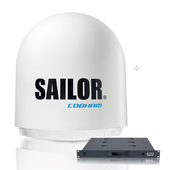
Service: Carry out the permitted operational/self-tests, inspect antennas, feeders, connectors, controls and cooling, and verify normal and emergency power where required. Check vessel identity, position and interfaces appropriate to the equipment type and review recurring alarms or logbook entries. A radio surveyor should confirm the installation and programmed data against the approved radio documentation.
Spare Parts: Carry fuses, approved handsets/microphones or control accessories where applicable, antenna connectors and feeder repair items, selected power-supply components and manufacturer-recommended interface/control spares. The spare scale should match the vessel's declared GMDSS maintenance method.
Use Cases: Used on merchant, offshore, passenger and workboat fleets for distress, safety and routine maritime communications according to the equipment's approved GMDSS function.
Cobham SATCOM SAILOR 800 VSAT
SAILOR 800 VSAT unverified
Stabilized
ja
Common Failures & Inspection Points
  • Loss of supply power from a tripped breaker, failed power unit, loose connection, or depleted reserve battery causes a dead unit, rebooting, or failure to transmit
  • Antenna, feeder, connector, or matching fault caused by corrosion, water ingress, or physical damage results in poor range, failed transmission, or weak received signals
  • Control-panel, display, keypad, or software faults can prevent channel selection, message handling, or normal operator input
  • Interface or position-data failure caused by wiring, configuration, or sensor faults can remove position information or connected-system data
  • Internal transmitter, receiver, or modem faults caused by component ageing or overheating can produce intermittent communication, alarms, or inability to establish a link
Service: Verify primary and reserve power, antenna and feeder condition, distress and safety functions permitted for routine testing, interfaces, audio quality, time and position inputs, and logged self-test results. Any regulatory test or adjustment must follow the vessel's radio procedures and manufacturer documentation.
Spare Parts: Carry the model-specific fuses, approved power-supply items, handset or microphone accessories, connector and sealing items, and critical interface or antenna components recommended by the manufacturer and vessel radio-maintenance plan.
Use Cases: Used on SOLAS merchant ships, offshore vessels, passenger ships, fishing vessels, workboats, and other craft requiring marine radio, distress, safety, or navigation communications.
Cobham SATCOM VSAT Ku-Band 37cm-C unverified
Antenna diameter cm
37
Band
Ku-Band
Stabilized
ja
Common Failures & Inspection Points
  • Loss of primary or reserve power from a tripped breaker, failed power unit, loose connection, or depleted battery causes a dead unit, rebooting, or failed transmission
  • Antenna, feeder, connector, or matching faults from corrosion, water ingress, or physical damage cause poor range or weak received signals
  • Control-panel, display, keypad, or software faults prevent channel selection, message handling, or operator input
  • Interface or position-data failure from wiring, configuration, or sensor faults removes position or connected-system data
  • Internal transmitter, receiver, or modem faults from component ageing or overheating cause intermittent communication, alarms, or inability to establish a link
Service: Verify primary and reserve power, antenna and feeder condition, permitted distress/safety self-tests, interfaces, audio quality, time and position inputs, and logged faults. Regulatory tests and adjustments must follow vessel radio procedures and manufacturer documentation.
Spare Parts: Carry model-specific fuses, approved power-supply items, handset or microphone accessories where relevant, connector and sealing items, and critical interface or antenna components recommended by the manufacturer.
Use Cases: Used on SOLAS merchant ships, offshore vessels, passenger ships, fishing vessels, workboats, and other craft requiring marine radio, distress, safety, or navigation communications.
Cobham SATCOM VSAT Ka-Band 37cm-C unverified
Antenna diameter cm
37
Band
Ka-Band
Stabilized
ja
Common Failures & Inspection Points
  • Loss of primary or reserve power from a tripped breaker, failed power unit, loose connection, or depleted battery causes a dead unit, rebooting, or failed transmission
  • Antenna, feeder, connector, or matching faults from corrosion, water ingress, or physical damage cause poor range or weak received signals
  • Control-panel, display, keypad, or software faults prevent channel selection, message handling, or operator input
  • Interface or position-data failure from wiring, configuration, or sensor faults removes position or connected-system data
  • Internal transmitter, receiver, or modem faults from component ageing or overheating cause intermittent communication, alarms, or inability to establish a link
Service: Verify primary and reserve power, antenna and feeder condition, permitted distress/safety self-tests, interfaces, audio quality, time and position inputs, and logged faults. Regulatory tests and adjustments must follow vessel radio procedures and manufacturer documentation.
Spare Parts: Carry model-specific fuses, approved power-supply items, handset or microphone accessories where relevant, connector and sealing items, and critical interface or antenna components recommended by the manufacturer.
Use Cases: Used on SOLAS merchant ships, offshore vessels, passenger ships, fishing vessels, workboats, and other craft requiring marine radio, distress, safety, or navigation communications.
Cobham SATCOM VSAT Ku-Band 45cm-C unverified
Antenna diameter cm
45
Band
Ku-Band
Stabilized
ja
Common Failures & Inspection Points
  • Loss of primary or reserve power from a tripped breaker, failed power unit, loose connection, or depleted battery causes a dead unit, rebooting, or failed transmission
  • Antenna, feeder, connector, or matching faults from corrosion, water ingress, or physical damage cause poor range or weak received signals
  • Control-panel, display, keypad, or software faults prevent channel selection, message handling, or operator input
  • Interface or position-data failure from wiring, configuration, or sensor faults removes position or connected-system data
  • Internal transmitter, receiver, or modem faults from component ageing or overheating cause intermittent communication, alarms, or inability to establish a link
Service: Verify primary and reserve power, antenna and feeder condition, permitted distress/safety self-tests, interfaces, audio quality, time and position inputs, and logged faults. Regulatory tests and adjustments must follow vessel radio procedures and manufacturer documentation.
Spare Parts: Carry model-specific fuses, approved power-supply items, handset or microphone accessories where relevant, connector and sealing items, and critical interface or antenna components recommended by the manufacturer.
Use Cases: Used on SOLAS merchant ships, offshore vessels, passenger ships, fishing vessels, workboats, and other craft requiring marine radio, distress, safety, or navigation communications.
Cobham SATCOM VSAT Ka-Band 45cm-C unverified
Antenna diameter cm
45
Band
Ka-Band
Stabilized
ja
Common Failures & Inspection Points
  • Loss of primary or reserve power from a tripped breaker, failed power unit, loose connection, or depleted battery causes a dead unit, rebooting, or failed transmission
  • Antenna, feeder, connector, or matching faults from corrosion, water ingress, or physical damage cause poor range or weak received signals
  • Control-panel, display, keypad, or software faults prevent channel selection, message handling, or operator input
  • Interface or position-data failure from wiring, configuration, or sensor faults removes position or connected-system data
  • Internal transmitter, receiver, or modem faults from component ageing or overheating cause intermittent communication, alarms, or inability to establish a link
Service: Verify primary and reserve power, antenna and feeder condition, permitted distress/safety self-tests, interfaces, audio quality, time and position inputs, and logged faults. Regulatory tests and adjustments must follow vessel radio procedures and manufacturer documentation.
Spare Parts: Carry model-specific fuses, approved power-supply items, handset or microphone accessories where relevant, connector and sealing items, and critical interface or antenna components recommended by the manufacturer.
Use Cases: Used on SOLAS merchant ships, offshore vessels, passenger ships, fishing vessels, workboats, and other craft requiring marine radio, distress, safety, or navigation communications.
Cobham SATCOM VSAT Ku-Band 60cm-C unverified
Antenna diameter cm
60
Band
Ku-Band
Stabilized
ja
Common Failures & Inspection Points
  • Loss of primary or reserve power from a tripped breaker, failed power unit, loose connection, or depleted battery causes a dead unit, rebooting, or failed transmission
  • Antenna, feeder, connector, or matching faults from corrosion, water ingress, or physical damage cause poor range or weak received signals
  • Control-panel, display, keypad, or software faults prevent channel selection, message handling, or operator input
  • Interface or position-data failure from wiring, configuration, or sensor faults removes position or connected-system data
  • Internal transmitter, receiver, or modem faults from component ageing or overheating cause intermittent communication, alarms, or inability to establish a link
Service: Verify primary and reserve power, antenna and feeder condition, permitted distress/safety self-tests, interfaces, audio quality, time and position inputs, and logged faults. Regulatory tests and adjustments must follow vessel radio procedures and manufacturer documentation.
Spare Parts: Carry model-specific fuses, approved power-supply items, handset or microphone accessories where relevant, connector and sealing items, and critical interface or antenna components recommended by the manufacturer.
Use Cases: Used on SOLAS merchant ships, offshore vessels, passenger ships, fishing vessels, workboats, and other craft requiring marine radio, distress, safety, or navigation communications.
Cobham SATCOM VSAT Ka-Band 60cm-C unverified
Antenna diameter cm
60
Band
Ka-Band
Stabilized
ja
Common Failures & Inspection Points
  • Loss of primary or reserve power from a tripped breaker, failed power unit, loose connection, or depleted battery causes a dead unit, rebooting, or failed transmission
  • Antenna, feeder, connector, or matching faults from corrosion, water ingress, or physical damage cause poor range or weak received signals
  • Control-panel, display, keypad, or software faults prevent channel selection, message handling, or operator input
  • Interface or position-data failure from wiring, configuration, or sensor faults removes position or connected-system data
  • Internal transmitter, receiver, or modem faults from component ageing or overheating cause intermittent communication, alarms, or inability to establish a link
Service: Verify primary and reserve power, antenna and feeder condition, permitted distress/safety self-tests, interfaces, audio quality, time and position inputs, and logged faults. Regulatory tests and adjustments must follow vessel radio procedures and manufacturer documentation.
Spare Parts: Carry model-specific fuses, approved power-supply items, handset or microphone accessories where relevant, connector and sealing items, and critical interface or antenna components recommended by the manufacturer.
Use Cases: Used on SOLAS merchant ships, offshore vessels, passenger ships, fishing vessels, workboats, and other craft requiring marine radio, distress, safety, or navigation communications.
Cobham SATCOM VSAT Ku-Band 85cm-C unverified
Antenna diameter cm
85
Band
Ku-Band
Stabilized
ja
Common Failures & Inspection Points
  • Loss of primary or reserve power from a tripped breaker, failed power unit, loose connection, or depleted battery causes a dead unit, rebooting, or failed transmission
  • Antenna, feeder, connector, or matching faults from corrosion, water ingress, or physical damage cause poor range or weak received signals
  • Control-panel, display, keypad, or software faults prevent channel selection, message handling, or operator input
  • Interface or position-data failure from wiring, configuration, or sensor faults removes position or connected-system data
  • Internal transmitter, receiver, or modem faults from component ageing or overheating cause intermittent communication, alarms, or inability to establish a link
Service: Verify primary and reserve power, antenna and feeder condition, permitted distress/safety self-tests, interfaces, audio quality, time and position inputs, and logged faults. Regulatory tests and adjustments must follow vessel radio procedures and manufacturer documentation.
Spare Parts: Carry model-specific fuses, approved power-supply items, handset or microphone accessories where relevant, connector and sealing items, and critical interface or antenna components recommended by the manufacturer.
Use Cases: Used on SOLAS merchant ships, offshore vessels, passenger ships, fishing vessels, workboats, and other craft requiring marine radio, distress, safety, or navigation communications.
Cobham SATCOM VSAT Ka-Band 85cm-C unverified
Antenna diameter cm
85
Band
Ka-Band
Stabilized
ja
Common Failures & Inspection Points
  • Loss of primary or reserve power from a tripped breaker, failed power unit, loose connection, or depleted battery causes a dead unit, rebooting, or failed transmission
  • Antenna, feeder, connector, or matching faults from corrosion, water ingress, or physical damage cause poor range or weak received signals
  • Control-panel, display, keypad, or software faults prevent channel selection, message handling, or operator input
  • Interface or position-data failure from wiring, configuration, or sensor faults removes position or connected-system data
  • Internal transmitter, receiver, or modem faults from component ageing or overheating cause intermittent communication, alarms, or inability to establish a link
Service: Verify primary and reserve power, antenna and feeder condition, permitted distress/safety self-tests, interfaces, audio quality, time and position inputs, and logged faults. Regulatory tests and adjustments must follow vessel radio procedures and manufacturer documentation.
Spare Parts: Carry model-specific fuses, approved power-supply items, handset or microphone accessories where relevant, connector and sealing items, and critical interface or antenna components recommended by the manufacturer.
Use Cases: Used on SOLAS merchant ships, offshore vessels, passenger ships, fishing vessels, workboats, and other craft requiring marine radio, distress, safety, or navigation communications.
Cobham SATCOM VSAT Ku-Band 100cm-C unverified
Antenna diameter cm
100
Band
Ku-Band
Stabilized
ja
Common Failures & Inspection Points
  • Loss of primary or reserve power from a tripped breaker, failed power unit, loose connection, or depleted battery causes a dead unit, rebooting, or failed transmission
  • Antenna, feeder, connector, or matching faults from corrosion, water ingress, or physical damage cause poor range or weak received signals
  • Control-panel, display, keypad, or software faults prevent channel selection, message handling, or operator input
  • Interface or position-data failure from wiring, configuration, or sensor faults removes position or connected-system data
  • Internal transmitter, receiver, or modem faults from component ageing or overheating cause intermittent communication, alarms, or inability to establish a link
Service: Verify primary and reserve power, antenna and feeder condition, permitted distress/safety self-tests, interfaces, audio quality, time and position inputs, and logged faults. Regulatory tests and adjustments must follow vessel radio procedures and manufacturer documentation.
Spare Parts: Carry model-specific fuses, approved power-supply items, handset or microphone accessories where relevant, connector and sealing items, and critical interface or antenna components recommended by the manufacturer.
Use Cases: Used on SOLAS merchant ships, offshore vessels, passenger ships, fishing vessels, workboats, and other craft requiring marine radio, distress, safety, or navigation communications.
Cobham SATCOM VSAT Ka-Band 100cm-C unverified
Antenna diameter cm
100
Band
Ka-Band
Stabilized
ja
Common Failures & Inspection Points
  • Loss of primary or reserve power from a tripped breaker, failed power unit, loose connection, or depleted battery causes a dead unit, rebooting, or failed transmission
  • Antenna, feeder, connector, or matching faults from corrosion, water ingress, or physical damage cause poor range or weak received signals
  • Control-panel, display, keypad, or software faults prevent channel selection, message handling, or operator input
  • Interface or position-data failure from wiring, configuration, or sensor faults removes position or connected-system data
  • Internal transmitter, receiver, or modem faults from component ageing or overheating cause intermittent communication, alarms, or inability to establish a link
Service: Verify primary and reserve power, antenna and feeder condition, permitted distress/safety self-tests, interfaces, audio quality, time and position inputs, and logged faults. Regulatory tests and adjustments must follow vessel radio procedures and manufacturer documentation.
Spare Parts: Carry model-specific fuses, approved power-supply items, handset or microphone accessories where relevant, connector and sealing items, and critical interface or antenna components recommended by the manufacturer.
Use Cases: Used on SOLAS merchant ships, offshore vessels, passenger ships, fishing vessels, workboats, and other craft requiring marine radio, distress, safety, or navigation communications.
Cobham SATCOM VSAT C-Band 100cm-C unverified
Antenna diameter cm
100
Band
C-Band
Stabilized
ja
Common Failures & Inspection Points
  • Loss of primary or reserve power from a tripped breaker, failed power unit, loose connection, or depleted battery causes a dead unit, rebooting, or failed transmission
  • Antenna, feeder, connector, or matching faults from corrosion, water ingress, or physical damage cause poor range or weak received signals
  • Control-panel, display, keypad, or software faults prevent channel selection, message handling, or operator input
  • Interface or position-data failure from wiring, configuration, or sensor faults removes position or connected-system data
  • Internal transmitter, receiver, or modem faults from component ageing or overheating cause intermittent communication, alarms, or inability to establish a link
Service: Verify primary and reserve power, antenna and feeder condition, permitted distress/safety self-tests, interfaces, audio quality, time and position inputs, and logged faults. Regulatory tests and adjustments must follow vessel radio procedures and manufacturer documentation.
Spare Parts: Carry model-specific fuses, approved power-supply items, handset or microphone accessories where relevant, connector and sealing items, and critical interface or antenna components recommended by the manufacturer.
Use Cases: Used on SOLAS merchant ships, offshore vessels, passenger ships, fishing vessels, workboats, and other craft requiring marine radio, distress, safety, or navigation communications.
Cobham SATCOM VSAT Ku-Band 130cm-C unverified
Antenna diameter cm
130
Band
Ku-Band
Stabilized
ja
Common Failures & Inspection Points
  • Loss of primary or reserve power from a tripped breaker, failed power unit, loose connection, or depleted battery causes a dead unit, rebooting, or failed transmission
  • Antenna, feeder, connector, or matching faults from corrosion, water ingress, or physical damage cause poor range or weak received signals
  • Control-panel, display, keypad, or software faults prevent channel selection, message handling, or operator input
  • Interface or position-data failure from wiring, configuration, or sensor faults removes position or connected-system data
  • Internal transmitter, receiver, or modem faults from component ageing or overheating cause intermittent communication, alarms, or inability to establish a link
Service: Verify primary and reserve power, antenna and feeder condition, permitted distress/safety self-tests, interfaces, audio quality, time and position inputs, and logged faults. Regulatory tests and adjustments must follow vessel radio procedures and manufacturer documentation.
Spare Parts: Carry model-specific fuses, approved power-supply items, handset or microphone accessories where relevant, connector and sealing items, and critical interface or antenna components recommended by the manufacturer.
Use Cases: Used on SOLAS merchant ships, offshore vessels, passenger ships, fishing vessels, workboats, and other craft requiring marine radio, distress, safety, or navigation communications.
Cobham SATCOM VSAT Ka-Band 130cm-C unverified
Antenna diameter cm
130
Band
Ka-Band
Stabilized
ja
Common Failures & Inspection Points
  • Loss of primary or reserve power from a tripped breaker, failed power unit, loose connection, or depleted battery causes a dead unit, rebooting, or failed transmission
  • Antenna, feeder, connector, or matching faults from corrosion, water ingress, or physical damage cause poor range or weak received signals
  • Control-panel, display, keypad, or software faults prevent channel selection, message handling, or operator input
  • Interface or position-data failure from wiring, configuration, or sensor faults removes position or connected-system data
  • Internal transmitter, receiver, or modem faults from component ageing or overheating cause intermittent communication, alarms, or inability to establish a link
Service: Verify primary and reserve power, antenna and feeder condition, permitted distress/safety self-tests, interfaces, audio quality, time and position inputs, and logged faults. Regulatory tests and adjustments must follow vessel radio procedures and manufacturer documentation.
Spare Parts: Carry model-specific fuses, approved power-supply items, handset or microphone accessories where relevant, connector and sealing items, and critical interface or antenna components recommended by the manufacturer.
Use Cases: Used on SOLAS merchant ships, offshore vessels, passenger ships, fishing vessels, workboats, and other craft requiring marine radio, distress, safety, or navigation communications.
Cobham SATCOM VSAT C-Band 130cm-C unverified
Antenna diameter cm
130
Band
C-Band
Stabilized
ja
Common Failures & Inspection Points
  • Loss of primary or reserve power from a tripped breaker, failed power unit, loose connection, or depleted battery causes a dead unit, rebooting, or failed transmission
  • Antenna, feeder, connector, or matching faults from corrosion, water ingress, or physical damage cause poor range or weak received signals
  • Control-panel, display, keypad, or software faults prevent channel selection, message handling, or operator input
  • Interface or position-data failure from wiring, configuration, or sensor faults removes position or connected-system data
  • Internal transmitter, receiver, or modem faults from component ageing or overheating cause intermittent communication, alarms, or inability to establish a link
Service: Verify primary and reserve power, antenna and feeder condition, permitted distress/safety self-tests, interfaces, audio quality, time and position inputs, and logged faults. Regulatory tests and adjustments must follow vessel radio procedures and manufacturer documentation.
Spare Parts: Carry model-specific fuses, approved power-supply items, handset or microphone accessories where relevant, connector and sealing items, and critical interface or antenna components recommended by the manufacturer.
Use Cases: Used on SOLAS merchant ships, offshore vessels, passenger ships, fishing vessels, workboats, and other craft requiring marine radio, distress, safety, or navigation communications.
Cobham SATCOM VSAT Ku-Band 240cm-C unverified
Antenna diameter cm
240
Band
Ku-Band
Stabilized
ja
Common Failures & Inspection Points
  • Loss of primary or reserve power from a tripped breaker, failed power unit, loose connection, or depleted battery causes a dead unit, rebooting, or failed transmission
  • Antenna, feeder, connector, or matching faults from corrosion, water ingress, or physical damage cause poor range or weak received signals
  • Control-panel, display, keypad, or software faults prevent channel selection, message handling, or operator input
  • Interface or position-data failure from wiring, configuration, or sensor faults removes position or connected-system data
  • Internal transmitter, receiver, or modem faults from component ageing or overheating cause intermittent communication, alarms, or inability to establish a link
Service: Verify primary and reserve power, antenna and feeder condition, permitted distress/safety self-tests, interfaces, audio quality, time and position inputs, and logged faults. Regulatory tests and adjustments must follow vessel radio procedures and manufacturer documentation.
Spare Parts: Carry model-specific fuses, approved power-supply items, handset or microphone accessories where relevant, connector and sealing items, and critical interface or antenna components recommended by the manufacturer.
Use Cases: Used on SOLAS merchant ships, offshore vessels, passenger ships, fishing vessels, workboats, and other craft requiring marine radio, distress, safety, or navigation communications.
Cobham SATCOM VSAT Ka-Band 240cm-C unverified
Antenna diameter cm
240
Band
Ka-Band
Stabilized
ja
Common Failures & Inspection Points
  • Loss of primary or reserve power from a tripped breaker, failed power unit, loose connection, or depleted battery causes a dead unit, rebooting, or failed transmission
  • Antenna, feeder, connector, or matching faults from corrosion, water ingress, or physical damage cause poor range or weak received signals
  • Control-panel, display, keypad, or software faults prevent channel selection, message handling, or operator input
  • Interface or position-data failure from wiring, configuration, or sensor faults removes position or connected-system data
  • Internal transmitter, receiver, or modem faults from component ageing or overheating cause intermittent communication, alarms, or inability to establish a link
Service: Verify primary and reserve power, antenna and feeder condition, permitted distress/safety self-tests, interfaces, audio quality, time and position inputs, and logged faults. Regulatory tests and adjustments must follow vessel radio procedures and manufacturer documentation.
Spare Parts: Carry model-specific fuses, approved power-supply items, handset or microphone accessories where relevant, connector and sealing items, and critical interface or antenna components recommended by the manufacturer.
Use Cases: Used on SOLAS merchant ships, offshore vessels, passenger ships, fishing vessels, workboats, and other craft requiring marine radio, distress, safety, or navigation communications.
Cobham SATCOM VSAT C-Band 240cm-C unverified
Antenna diameter cm
240
Band
C-Band
Stabilized
ja
Common Failures & Inspection Points
  • Loss of primary or reserve power from a tripped breaker, failed power unit, loose connection, or depleted battery causes a dead unit, rebooting, or failed transmission
  • Antenna, feeder, connector, or matching faults from corrosion, water ingress, or physical damage cause poor range or weak received signals
  • Control-panel, display, keypad, or software faults prevent channel selection, message handling, or operator input
  • Interface or position-data failure from wiring, configuration, or sensor faults removes position or connected-system data
  • Internal transmitter, receiver, or modem faults from component ageing or overheating cause intermittent communication, alarms, or inability to establish a link
Service: Verify primary and reserve power, antenna and feeder condition, permitted distress/safety self-tests, interfaces, audio quality, time and position inputs, and logged faults. Regulatory tests and adjustments must follow vessel radio procedures and manufacturer documentation.
Spare Parts: Carry model-specific fuses, approved power-supply items, handset or microphone accessories where relevant, connector and sealing items, and critical interface or antenna components recommended by the manufacturer.
Use Cases: Used on SOLAS merchant ships, offshore vessels, passenger ships, fishing vessels, workboats, and other craft requiring marine radio, distress, safety, or navigation communications.

Epak

20
DynaSat D60 unverified
Stabilized
ja
Common Failures & Inspection Points
  • Antenna obstruction, tracking fault or damaged radome causes loss of satellite lock, poor signal quality or repeated connection drops
  • Modem, terminal or network-interface failure causes unavailable data or voice services despite normal ship power
  • Power-supply or UPS faults cause terminal rebooting, blank displays or complete service loss
  • Cabling, connector or Ethernet faults cause intermittent connectivity or loss of interfaces to ship systems
  • Configuration, registration or service-provider problems prevent log-in or message transfer even when hardware tests appear normal
Service: Inspect antenna or radome, mounting, cabling, indoor units, power supply and network interfaces. Review signal-quality and terminal logs for recurring dropouts. Confirm vessel identity, service configuration and emergency functions where applicable. Antenna alignment, software and network settings should only be changed using approved documentation.
Spare Parts: Carry fuses, power supplies where supported, network and RF cables, connectors, approved modem or terminal modules where vessel policy requires them and backed-up configuration information.
Use Cases: Ocean-going merchant, passenger and offshore vessels requiring long-range safety, operational or crew communications.
DynaSat D80 unverified
Stabilized
ja
Common Failures & Inspection Points
  • Antenna obstruction, tracking fault or damaged radome causes loss of satellite lock, poor signal quality or repeated connection drops
  • Modem, terminal or network-interface failure causes unavailable data or voice services despite normal ship power
  • Power-supply or UPS faults cause terminal rebooting, blank displays or complete service loss
  • Cabling, connector or Ethernet faults cause intermittent connectivity or loss of interfaces to ship systems
  • Configuration, registration or service-provider problems prevent log-in or message transfer even when hardware tests appear normal
Service: Inspect antenna or radome, mounting, cabling, indoor units, power supply and network interfaces. Review signal-quality and terminal logs for recurring dropouts. Confirm vessel identity, service configuration and emergency functions where applicable. Antenna alignment, software and network settings should only be changed using approved documentation.
Spare Parts: Carry fuses, power supplies where supported, network and RF cables, connectors, approved modem or terminal modules where vessel policy requires them and backed-up configuration information.
Use Cases: Ocean-going merchant, passenger and offshore vessels requiring long-range safety, operational or crew communications.
DynaSat D100 unverified
Stabilized
ja
Common Failures & Inspection Points
  • Antenna obstruction, tracking fault or damaged radome causes loss of satellite lock, poor signal quality or repeated connection drops
  • Modem, terminal or network-interface failure causes unavailable data or voice services despite normal ship power
  • Power-supply or UPS faults cause terminal rebooting, blank displays or complete service loss
  • Cabling, connector or Ethernet faults cause intermittent connectivity or loss of interfaces to ship systems
  • Configuration, registration or service-provider problems prevent log-in or message transfer even when hardware tests appear normal
Service: Inspect antenna or radome, mounting, cabling, indoor units, power supply and network interfaces. Review signal-quality and terminal logs for recurring dropouts. Confirm vessel identity, service configuration and emergency functions where applicable. Antenna alignment, software and network settings should only be changed using approved documentation.
Spare Parts: Carry fuses, power supplies where supported, network and RF cables, connectors, approved modem or terminal modules where vessel policy requires them and backed-up configuration information.
Use Cases: Ocean-going merchant, passenger and offshore vessels requiring long-range safety, operational or crew communications.
Epak VSAT Ku-Band 37cm-C unverified
Antenna diameter cm
37
Band
Ku-Band
Stabilized
ja
Common Failures & Inspection Points
  • Loss of supply power from a tripped breaker, failed power unit, loose connection, or depleted reserve battery causes a dead unit, rebooting, or failure to transmit
  • Antenna, feeder, connector, or matching fault caused by corrosion, water ingress, or physical damage results in poor range, failed transmission, or weak received signals
  • Control-panel, display, keypad, or software faults can prevent channel selection, message handling, or normal operator input
  • Interface or position-data failure caused by wiring, configuration, or sensor faults can remove position information or connected-system data
  • Internal transmitter, receiver, or modem faults caused by component ageing or overheating can produce intermittent communication, alarms, or inability to establish a link
Service: Verify primary and reserve power, antenna and feeder condition, distress and safety functions permitted for routine testing, interfaces, audio quality, time and position inputs, and logged self-test results. Any regulatory test or adjustment must follow the vessel's radio procedures and manufacturer documentation.
Spare Parts: Carry the model-specific fuses, approved power-supply items, handset or microphone accessories, connector and sealing items, and critical interface or antenna components recommended by the manufacturer and vessel radio-maintenance plan.
Use Cases: Used on SOLAS merchant ships, offshore vessels, passenger ships, fishing vessels, workboats, and other craft requiring marine radio, distress, safety, or navigation communications.
Epak VSAT Ka-Band 37cm-C unverified
Antenna diameter cm
37
Band
Ka-Band
Stabilized
ja
Common Failures & Inspection Points
  • Loss of supply power from a tripped breaker, failed power unit, loose connection, or depleted reserve battery causes a dead unit, rebooting, or failure to transmit
  • Antenna, feeder, connector, or matching fault caused by corrosion, water ingress, or physical damage results in poor range, failed transmission, or weak received signals
  • Control-panel, display, keypad, or software faults can prevent channel selection, message handling, or normal operator input
  • Interface or position-data failure caused by wiring, configuration, or sensor faults can remove position information or connected-system data
  • Internal transmitter, receiver, or modem faults caused by component ageing or overheating can produce intermittent communication, alarms, or inability to establish a link
Service: Verify primary and reserve power, antenna and feeder condition, distress and safety functions permitted for routine testing, interfaces, audio quality, time and position inputs, and logged self-test results. Any regulatory test or adjustment must follow the vessel's radio procedures and manufacturer documentation.
Spare Parts: Carry the model-specific fuses, approved power-supply items, handset or microphone accessories, connector and sealing items, and critical interface or antenna components recommended by the manufacturer and vessel radio-maintenance plan.
Use Cases: Used on SOLAS merchant ships, offshore vessels, passenger ships, fishing vessels, workboats, and other craft requiring marine radio, distress, safety, or navigation communications.
Epak VSAT Ku-Band 45cm-C unverified
Antenna diameter cm
45
Band
Ku-Band
Stabilized
ja
Common Failures & Inspection Points
  • Loss of supply power from a tripped breaker, failed power unit, loose connection, or depleted reserve battery causes a dead unit, rebooting, or failure to transmit
  • Antenna, feeder, connector, or matching fault caused by corrosion, water ingress, or physical damage results in poor range, failed transmission, or weak received signals
  • Control-panel, display, keypad, or software faults can prevent channel selection, message handling, or normal operator input
  • Interface or position-data failure caused by wiring, configuration, or sensor faults can remove position information or connected-system data
  • Internal transmitter, receiver, or modem faults caused by component ageing or overheating can produce intermittent communication, alarms, or inability to establish a link
Service: Verify primary and reserve power, antenna and feeder condition, distress and safety functions permitted for routine testing, interfaces, audio quality, time and position inputs, and logged self-test results. Any regulatory test or adjustment must follow the vessel's radio procedures and manufacturer documentation.
Spare Parts: Carry the model-specific fuses, approved power-supply items, handset or microphone accessories, connector and sealing items, and critical interface or antenna components recommended by the manufacturer and vessel radio-maintenance plan.
Use Cases: Used on SOLAS merchant ships, offshore vessels, passenger ships, fishing vessels, workboats, and other craft requiring marine radio, distress, safety, or navigation communications.
Epak VSAT Ka-Band 45cm-C unverified
Antenna diameter cm
45
Band
Ka-Band
Stabilized
ja
Common Failures & Inspection Points
  • Loss of supply power from a tripped breaker, failed power unit, loose connection, or depleted reserve battery causes a dead unit, rebooting, or failure to transmit
  • Antenna, feeder, connector, or matching fault caused by corrosion, water ingress, or physical damage results in poor range, failed transmission, or weak received signals
  • Control-panel, display, keypad, or software faults can prevent channel selection, message handling, or normal operator input
  • Interface or position-data failure caused by wiring, configuration, or sensor faults can remove position information or connected-system data
  • Internal transmitter, receiver, or modem faults caused by component ageing or overheating can produce intermittent communication, alarms, or inability to establish a link
Service: Verify primary and reserve power, antenna and feeder condition, distress and safety functions permitted for routine testing, interfaces, audio quality, time and position inputs, and logged self-test results. Any regulatory test or adjustment must follow the vessel's radio procedures and manufacturer documentation.
Spare Parts: Carry the model-specific fuses, approved power-supply items, handset or microphone accessories, connector and sealing items, and critical interface or antenna components recommended by the manufacturer and vessel radio-maintenance plan.
Use Cases: Used on SOLAS merchant ships, offshore vessels, passenger ships, fishing vessels, workboats, and other craft requiring marine radio, distress, safety, or navigation communications.
Epak VSAT Ku-Band 60cm-C unverified
Antenna diameter cm
60
Band
Ku-Band
Stabilized
ja
Common Failures & Inspection Points
  • Loss of supply power from a tripped breaker, failed power unit, loose connection, or depleted reserve battery causes a dead unit, rebooting, or failure to transmit
  • Antenna, feeder, connector, or matching fault caused by corrosion, water ingress, or physical damage results in poor range, failed transmission, or weak received signals
  • Control-panel, display, keypad, or software faults can prevent channel selection, message handling, or normal operator input
  • Interface or position-data failure caused by wiring, configuration, or sensor faults can remove position information or connected-system data
  • Internal transmitter, receiver, or modem faults caused by component ageing or overheating can produce intermittent communication, alarms, or inability to establish a link
Service: Verify primary and reserve power, antenna and feeder condition, distress and safety functions permitted for routine testing, interfaces, audio quality, time and position inputs, and logged self-test results. Any regulatory test or adjustment must follow the vessel's radio procedures and manufacturer documentation.
Spare Parts: Carry the model-specific fuses, approved power-supply items, handset or microphone accessories, connector and sealing items, and critical interface or antenna components recommended by the manufacturer and vessel radio-maintenance plan.
Use Cases: Used on SOLAS merchant ships, offshore vessels, passenger ships, fishing vessels, workboats, and other craft requiring marine radio, distress, safety, or navigation communications.
Epak VSAT Ka-Band 60cm-C unverified
Antenna diameter cm
60
Band
Ka-Band
Stabilized
ja
Common Failures & Inspection Points
  • Loss of supply power from a tripped breaker, failed power unit, loose connection, or depleted reserve battery causes a dead unit, rebooting, or failure to transmit
  • Antenna, feeder, connector, or matching fault caused by corrosion, water ingress, or physical damage results in poor range, failed transmission, or weak received signals
  • Control-panel, display, keypad, or software faults can prevent channel selection, message handling, or normal operator input
  • Interface or position-data failure caused by wiring, configuration, or sensor faults can remove position information or connected-system data
  • Internal transmitter, receiver, or modem faults caused by component ageing or overheating can produce intermittent communication, alarms, or inability to establish a link
Service: Verify primary and reserve power, antenna and feeder condition, distress and safety functions permitted for routine testing, interfaces, audio quality, time and position inputs, and logged self-test results. Any regulatory test or adjustment must follow the vessel's radio procedures and manufacturer documentation.
Spare Parts: Carry the model-specific fuses, approved power-supply items, handset or microphone accessories, connector and sealing items, and critical interface or antenna components recommended by the manufacturer and vessel radio-maintenance plan.
Use Cases: Used on SOLAS merchant ships, offshore vessels, passenger ships, fishing vessels, workboats, and other craft requiring marine radio, distress, safety, or navigation communications.
Epak VSAT Ku-Band 85cm-C unverified
Antenna diameter cm
85
Band
Ku-Band
Stabilized
ja
Common Failures & Inspection Points
  • Loss of supply power from a tripped breaker, failed power unit, loose connection, or depleted reserve battery causes a dead unit, rebooting, or failure to transmit
  • Antenna, feeder, connector, or matching fault caused by corrosion, water ingress, or physical damage results in poor range, failed transmission, or weak received signals
  • Control-panel, display, keypad, or software faults can prevent channel selection, message handling, or normal operator input
  • Interface or position-data failure caused by wiring, configuration, or sensor faults can remove position information or connected-system data
  • Internal transmitter, receiver, or modem faults caused by component ageing or overheating can produce intermittent communication, alarms, or inability to establish a link
Service: Verify primary and reserve power, antenna and feeder condition, distress and safety functions permitted for routine testing, interfaces, audio quality, time and position inputs, and logged self-test results. Any regulatory test or adjustment must follow the vessel's radio procedures and manufacturer documentation.
Spare Parts: Carry the model-specific fuses, approved power-supply items, handset or microphone accessories, connector and sealing items, and critical interface or antenna components recommended by the manufacturer and vessel radio-maintenance plan.
Use Cases: Used on SOLAS merchant ships, offshore vessels, passenger ships, fishing vessels, workboats, and other craft requiring marine radio, distress, safety, or navigation communications.
Epak VSAT Ka-Band 85cm-C unverified
Antenna diameter cm
85
Band
Ka-Band
Stabilized
ja
Common Failures & Inspection Points
  • Loss of supply power from a tripped breaker, failed power unit, loose connection, or depleted reserve battery causes a dead unit, rebooting, or failure to transmit
  • Antenna, feeder, connector, or matching fault caused by corrosion, water ingress, or physical damage results in poor range, failed transmission, or weak received signals
  • Control-panel, display, keypad, or software faults can prevent channel selection, message handling, or normal operator input
  • Interface or position-data failure caused by wiring, configuration, or sensor faults can remove position information or connected-system data
  • Internal transmitter, receiver, or modem faults caused by component ageing or overheating can produce intermittent communication, alarms, or inability to establish a link
Service: Verify primary and reserve power, antenna and feeder condition, distress and safety functions permitted for routine testing, interfaces, audio quality, time and position inputs, and logged self-test results. Any regulatory test or adjustment must follow the vessel's radio procedures and manufacturer documentation.
Spare Parts: Carry the model-specific fuses, approved power-supply items, handset or microphone accessories, connector and sealing items, and critical interface or antenna components recommended by the manufacturer and vessel radio-maintenance plan.
Use Cases: Used on SOLAS merchant ships, offshore vessels, passenger ships, fishing vessels, workboats, and other craft requiring marine radio, distress, safety, or navigation communications.
Epak VSAT Ku-Band 100cm-C unverified
Antenna diameter cm
100
Band
Ku-Band
Stabilized
ja
Common Failures & Inspection Points
  • Antenna, feeder or tuning fault caused by corrosion, damaged cabling or poor connections, resulting in weak transmission, reception problems or equipment alarms
  • Power-supply or backup-battery failure caused by charger defects, aged batteries or wiring faults, resulting in loss of availability when main power is removed
  • Transmitter or receiver failure caused by RF-component or electronic faults, resulting in inability to establish communications or receive expected traffic
  • Position or time-input failure caused by GNSS or network faults, resulting in missing or incorrect data in distress or DSC functions
  • Control, display or software fault caused by hardware failure or configuration problems, resulting in frozen controls, error messages or unavailable functions
Service: Perform operational and self-tests permitted by the vessel's procedures without generating unintended distress alerts. Inspect antennas, feeders, grounding, power supplies, backup batteries and connected navigation-data inputs. Verify station identity, position input, time and configured communication services against approved records. Check printers, handsets, microphones and alarm interfaces where fitted. Maintain software, licenses and service subscriptions required by the installed system. Refer to manufacturer and regulatory documentation for exact test methods, battery criteria and approved servicing.
Spare Parts: Keep fuses, handset or microphone accessories, printer consumables where applicable, selected power-supply components and manufacturer-recommended electronic spares. Antenna or feeder repair materials and backup-battery arrangements should reflect the vessel's redundancy plan. Preserve type approval and programmed identity when replacing core units.
Use Cases: Distress, urgency, safety and routine maritime communications within the vessel's GMDSS and operational communications fit.
Epak VSAT Ka-Band 100cm-C unverified
Antenna diameter cm
100
Band
Ka-Band
Stabilized
ja
Common Failures & Inspection Points
  • Antenna, feeder or tuning fault caused by corrosion, damaged cabling or poor connections, resulting in weak transmission, reception problems or equipment alarms
  • Power-supply or backup-battery failure caused by charger defects, aged batteries or wiring faults, resulting in loss of availability when main power is removed
  • Transmitter or receiver failure caused by RF-component or electronic faults, resulting in inability to establish communications or receive expected traffic
  • Position or time-input failure caused by GNSS or network faults, resulting in missing or incorrect data in distress or DSC functions
  • Control, display or software fault caused by hardware failure or configuration problems, resulting in frozen controls, error messages or unavailable functions
Service: Perform operational and self-tests permitted by the vessel's procedures without generating unintended distress alerts. Inspect antennas, feeders, grounding, power supplies, backup batteries and connected navigation-data inputs. Verify station identity, position input, time and configured communication services against approved records. Check printers, handsets, microphones and alarm interfaces where fitted. Maintain software, licenses and service subscriptions required by the installed system. Refer to manufacturer and regulatory documentation for exact test methods, battery criteria and approved servicing.
Spare Parts: Keep fuses, handset or microphone accessories, printer consumables where applicable, selected power-supply components and manufacturer-recommended electronic spares. Antenna or feeder repair materials and backup-battery arrangements should reflect the vessel's redundancy plan. Preserve type approval and programmed identity when replacing core units.
Use Cases: Distress, urgency, safety and routine maritime communications within the vessel's GMDSS and operational communications fit.
Epak VSAT C-Band 100cm-C unverified
Antenna diameter cm
100
Band
C-Band
Stabilized
ja
Common Failures & Inspection Points
  • Loss of supply power from a tripped breaker, failed power unit, loose connection, or depleted reserve battery causes a dead unit, rebooting, or failure to transmit
  • Antenna, feeder, connector, or matching fault caused by corrosion, water ingress, or physical damage results in poor range, failed transmission, or weak received signals
  • Control-panel, display, keypad, or software faults can prevent channel selection, message handling, or normal operator input
  • Interface or position-data failure caused by wiring, configuration, or sensor faults can remove position information or connected-system data
  • Internal transmitter, receiver, or modem faults caused by component ageing or overheating can produce intermittent communication, alarms, or inability to establish a link
Service: Verify primary and reserve power, antenna and feeder condition, distress and safety functions permitted for routine testing, interfaces, audio quality, time and position inputs, and logged self-test results. Any regulatory test or adjustment must follow the vessel's radio procedures and manufacturer documentation.
Spare Parts: Carry the model-specific fuses, approved power-supply items, handset or microphone accessories, connector and sealing items, and critical interface or antenna components recommended by the manufacturer and vessel radio-maintenance plan.
Use Cases: Used on SOLAS merchant ships, offshore vessels, passenger ships, fishing vessels, workboats, and other craft requiring marine radio, distress, safety, or navigation communications.
Epak VSAT Ku-Band 130cm-C unverified
Antenna diameter cm
130
Band
Ku-Band
Stabilized
ja
Common Failures & Inspection Points
  • Antenna, feeder or tuning fault caused by corrosion, damaged cabling or poor connections, resulting in weak transmission, reception problems or equipment alarms
  • Power-supply or backup-battery failure caused by charger defects, aged batteries or wiring faults, resulting in loss of availability when main power is removed
  • Transmitter or receiver failure caused by RF-component or electronic faults, resulting in inability to establish communications or receive expected traffic
  • Position or time-input failure caused by GNSS or network faults, resulting in missing or incorrect data in distress or DSC functions
  • Control, display or software fault caused by hardware failure or configuration problems, resulting in frozen controls, error messages or unavailable functions
Service: Perform operational and self-tests permitted by the vessel's procedures without generating unintended distress alerts. Inspect antennas, feeders, grounding, power supplies, backup batteries and connected navigation-data inputs. Verify station identity, position input, time and configured communication services against approved records. Check printers, handsets, microphones and alarm interfaces where fitted. Maintain software, licenses and service subscriptions required by the installed system. Refer to manufacturer and regulatory documentation for exact test methods, battery criteria and approved servicing.
Spare Parts: Keep fuses, handset or microphone accessories, printer consumables where applicable, selected power-supply components and manufacturer-recommended electronic spares. Antenna or feeder repair materials and backup-battery arrangements should reflect the vessel's redundancy plan. Preserve type approval and programmed identity when replacing core units.
Use Cases: Distress, urgency, safety and routine maritime communications within the vessel's GMDSS and operational communications fit.
Epak VSAT Ka-Band 130cm-C unverified
Antenna diameter cm
130
Band
Ka-Band
Stabilized
ja
Common Failures & Inspection Points
  • Antenna, feeder or tuning fault caused by corrosion, damaged cabling or poor connections, resulting in weak transmission, reception problems or equipment alarms
  • Power-supply or backup-battery failure caused by charger defects, aged batteries or wiring faults, resulting in loss of availability when main power is removed
  • Transmitter or receiver failure caused by RF-component or electronic faults, resulting in inability to establish communications or receive expected traffic
  • Position or time-input failure caused by GNSS or network faults, resulting in missing or incorrect data in distress or DSC functions
  • Control, display or software fault caused by hardware failure or configuration problems, resulting in frozen controls, error messages or unavailable functions
Service: Perform operational and self-tests permitted by the vessel's procedures without generating unintended distress alerts. Inspect antennas, feeders, grounding, power supplies, backup batteries and connected navigation-data inputs. Verify station identity, position input, time and configured communication services against approved records. Check printers, handsets, microphones and alarm interfaces where fitted. Maintain software, licenses and service subscriptions required by the installed system. Refer to manufacturer and regulatory documentation for exact test methods, battery criteria and approved servicing.
Spare Parts: Keep fuses, handset or microphone accessories, printer consumables where applicable, selected power-supply components and manufacturer-recommended electronic spares. Antenna or feeder repair materials and backup-battery arrangements should reflect the vessel's redundancy plan. Preserve type approval and programmed identity when replacing core units.
Use Cases: Distress, urgency, safety and routine maritime communications within the vessel's GMDSS and operational communications fit.
Epak VSAT C-Band 130cm-C unverified
Antenna diameter cm
130
Band
C-Band
Stabilized
ja
Common Failures & Inspection Points
  • Loss of supply power from a tripped breaker, failed power unit, loose connection, or depleted reserve battery causes a dead unit, rebooting, or failure to transmit
  • Antenna, feeder, connector, or matching fault caused by corrosion, water ingress, or physical damage results in poor range, failed transmission, or weak received signals
  • Control-panel, display, keypad, or software faults can prevent channel selection, message handling, or normal operator input
  • Interface or position-data failure caused by wiring, configuration, or sensor faults can remove position information or connected-system data
  • Internal transmitter, receiver, or modem faults caused by component ageing or overheating can produce intermittent communication, alarms, or inability to establish a link
Service: Verify primary and reserve power, antenna and feeder condition, distress and safety functions permitted for routine testing, interfaces, audio quality, time and position inputs, and logged self-test results. Any regulatory test or adjustment must follow the vessel's radio procedures and manufacturer documentation.
Spare Parts: Carry the model-specific fuses, approved power-supply items, handset or microphone accessories, connector and sealing items, and critical interface or antenna components recommended by the manufacturer and vessel radio-maintenance plan.
Use Cases: Used on SOLAS merchant ships, offshore vessels, passenger ships, fishing vessels, workboats, and other craft requiring marine radio, distress, safety, or navigation communications.
Epak VSAT Ku-Band 240cm-C unverified
Antenna diameter cm
240
Band
Ku-Band
Stabilized
ja
Common Failures & Inspection Points
  • Antenna, feeder or tuning fault caused by corrosion, damaged cabling or poor connections, resulting in weak transmission, reception problems or equipment alarms
  • Power-supply or backup-battery failure caused by charger defects, aged batteries or wiring faults, resulting in loss of availability when main power is removed
  • Transmitter or receiver failure caused by RF-component or electronic faults, resulting in inability to establish communications or receive expected traffic
  • Position or time-input failure caused by GNSS or network faults, resulting in missing or incorrect data in distress or DSC functions
  • Control, display or software fault caused by hardware failure or configuration problems, resulting in frozen controls, error messages or unavailable functions
Service: Perform operational and self-tests permitted by the vessel's procedures without generating unintended distress alerts. Inspect antennas, feeders, grounding, power supplies, backup batteries and connected navigation-data inputs. Verify station identity, position input, time and configured communication services against approved records. Check printers, handsets, microphones and alarm interfaces where fitted. Maintain software, licenses and service subscriptions required by the installed system. Refer to manufacturer and regulatory documentation for exact test methods, battery criteria and approved servicing.
Spare Parts: Keep fuses, handset or microphone accessories, printer consumables where applicable, selected power-supply components and manufacturer-recommended electronic spares. Antenna or feeder repair materials and backup-battery arrangements should reflect the vessel's redundancy plan. Preserve type approval and programmed identity when replacing core units.
Use Cases: Distress, urgency, safety and routine maritime communications within the vessel's GMDSS and operational communications fit.
Epak VSAT Ka-Band 240cm-C unverified
Antenna diameter cm
240
Band
Ka-Band
Stabilized
ja
Common Failures & Inspection Points
  • Antenna, feeder or tuning fault caused by corrosion, damaged cabling or poor connections, resulting in weak transmission, reception problems or equipment alarms
  • Power-supply or backup-battery failure caused by charger defects, aged batteries or wiring faults, resulting in loss of availability when main power is removed
  • Transmitter or receiver failure caused by RF-component or electronic faults, resulting in inability to establish communications or receive expected traffic
  • Position or time-input failure caused by GNSS or network faults, resulting in missing or incorrect data in distress or DSC functions
  • Control, display or software fault caused by hardware failure or configuration problems, resulting in frozen controls, error messages or unavailable functions
Service: Perform operational and self-tests permitted by the vessel's procedures without generating unintended distress alerts. Inspect antennas, feeders, grounding, power supplies, backup batteries and connected navigation-data inputs. Verify station identity, position input, time and configured communication services against approved records. Check printers, handsets, microphones and alarm interfaces where fitted. Maintain software, licenses and service subscriptions required by the installed system. Refer to manufacturer and regulatory documentation for exact test methods, battery criteria and approved servicing.
Spare Parts: Keep fuses, handset or microphone accessories, printer consumables where applicable, selected power-supply components and manufacturer-recommended electronic spares. Antenna or feeder repair materials and backup-battery arrangements should reflect the vessel's redundancy plan. Preserve type approval and programmed identity when replacing core units.
Use Cases: Distress, urgency, safety and routine maritime communications within the vessel's GMDSS and operational communications fit.
Epak VSAT C-Band 240cm-C unverified
Antenna diameter cm
240
Band
C-Band
Stabilized
ja
Common Failures & Inspection Points
  • Loss of supply power from a tripped breaker, failed power unit, loose connection, or depleted reserve battery causes a dead unit, rebooting, or failure to transmit
  • Antenna, feeder, connector, or matching fault caused by corrosion, water ingress, or physical damage results in poor range, failed transmission, or weak received signals
  • Control-panel, display, keypad, or software faults can prevent channel selection, message handling, or normal operator input
  • Interface or position-data failure caused by wiring, configuration, or sensor faults can remove position information or connected-system data
  • Internal transmitter, receiver, or modem faults caused by component ageing or overheating can produce intermittent communication, alarms, or inability to establish a link
Service: Verify primary and reserve power, antenna and feeder condition, distress and safety functions permitted for routine testing, interfaces, audio quality, time and position inputs, and logged self-test results. Any regulatory test or adjustment must follow the vessel's radio procedures and manufacturer documentation.
Spare Parts: Carry the model-specific fuses, approved power-supply items, handset or microphone accessories, connector and sealing items, and critical interface or antenna components recommended by the manufacturer and vessel radio-maintenance plan.
Use Cases: Used on SOLAS merchant ships, offshore vessels, passenger ships, fishing vessels, workboats, and other craft requiring marine radio, distress, safety, or navigation communications.

Iridium

10
Iridium 9575 unverified
Network
Iridium
Portable
ja
Common Failures & Inspection Points
  • Antenna obstruction, tracking fault or damaged radome causes loss of satellite lock, poor signal quality or repeated connection drops
  • Modem, terminal or network-interface failure causes unavailable data or voice services despite normal ship power
  • Power-supply or UPS faults cause terminal rebooting, blank displays or complete service loss
  • Cabling, connector or Ethernet faults cause intermittent connectivity or loss of interfaces to ship systems
  • Configuration, registration or service-provider problems prevent log-in or message transfer even when hardware tests appear normal
Service: Inspect antenna or radome, mounting, cabling, indoor units, power supply and network interfaces. Review signal-quality and terminal logs for recurring dropouts. Confirm vessel identity, service configuration and emergency functions where applicable. Antenna alignment, software and network settings should only be changed using approved documentation.
Spare Parts: Carry fuses, power supplies where supported, network and RF cables, connectors, approved modem or terminal modules where vessel policy requires them and backed-up configuration information.
Use Cases: Ocean-going merchant, passenger and offshore vessels requiring long-range safety, operational or crew communications.
Iridium 9555 unverified
Network
Iridium
Portable
ja
Common Failures & Inspection Points
  • Antenna obstruction, tracking fault or damaged radome causes loss of satellite lock, poor signal quality or repeated connection drops
  • Modem, terminal or network-interface failure causes unavailable data or voice services despite normal ship power
  • Power-supply or UPS faults cause terminal rebooting, blank displays or complete service loss
  • Cabling, connector or Ethernet faults cause intermittent connectivity or loss of interfaces to ship systems
  • Configuration, registration or service-provider problems prevent log-in or message transfer even when hardware tests appear normal
Service: Inspect antenna or radome, mounting, cabling, indoor units, power supply and network interfaces. Review signal-quality and terminal logs for recurring dropouts. Confirm vessel identity, service configuration and emergency functions where applicable. Antenna alignment, software and network settings should only be changed using approved documentation.
Spare Parts: Carry fuses, power supplies where supported, network and RF cables, connectors, approved modem or terminal modules where vessel policy requires them and backed-up configuration information.
Use Cases: Ocean-going merchant, passenger and offshore vessels requiring long-range safety, operational or crew communications.
Iridium GO! unverified
Network
Iridium
Portable
ja
Common Failures & Inspection Points
  • Antenna obstruction, tracking fault or damaged radome causes loss of satellite lock, poor signal quality or repeated connection drops
  • Modem, terminal or network-interface failure causes unavailable data or voice services despite normal ship power
  • Power-supply or UPS faults cause terminal rebooting, blank displays or complete service loss
  • Cabling, connector or Ethernet faults cause intermittent connectivity or loss of interfaces to ship systems
  • Configuration, registration or service-provider problems prevent log-in or message transfer even when hardware tests appear normal
Service: Inspect antenna or radome, mounting, cabling, indoor units, power supply and network interfaces. Review signal-quality and terminal logs for recurring dropouts. Confirm vessel identity, service configuration and emergency functions where applicable. Antenna alignment, software and network settings should only be changed using approved documentation.
Spare Parts: Carry fuses, power supplies where supported, network and RF cables, connectors, approved modem or terminal modules where vessel policy requires them and backed-up configuration information.
Use Cases: Ocean-going merchant, passenger and offshore vessels requiring long-range safety, operational or crew communications.
Iridium Certus 100 unverified
Network
Iridium
Portable
nein
Common Failures & Inspection Points
  • Transmitter or receiver failure caused by RF, antenna, feeder or power faults, noticed as poor range, failed checks or loss of reception
  • Antenna/feed-line deterioration caused by corrosion, water ingress or mechanical damage, noticed as intermittent operation or reduced range
  • Control or audio failure caused by handset, microphone, display, keypad or controller faults, noticed as inability to operate normal functions
  • Position/identity or data-interface failure caused by wiring or configuration faults, noticed as missing or incorrect safety data
  • Power-source failure caused by breaker, fuse, converter or emergency-supply faults, noticed as dead equipment or loss of required GMDSS availability
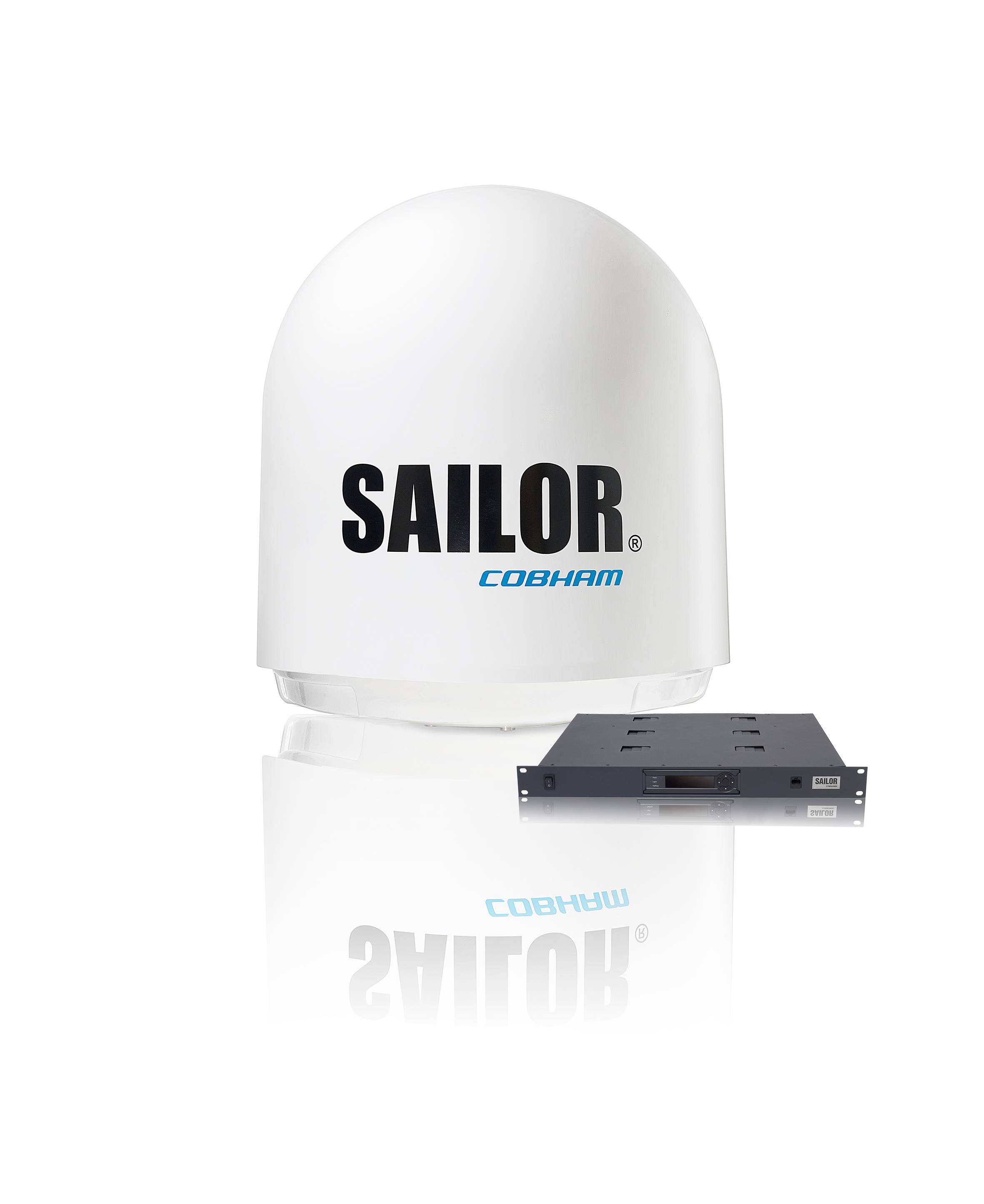
Service: Carry out the permitted operational/self-tests, inspect antennas, feeders, connectors, controls and cooling, and verify normal and emergency power where required. Check vessel identity, position and interfaces appropriate to the equipment type and review recurring alarms or logbook entries. A radio surveyor should confirm the installation and programmed data against the approved radio documentation.
Spare Parts: Carry fuses, approved handsets/microphones or control accessories where applicable, antenna connectors and feeder repair items, selected power-supply components and manufacturer-recommended interface/control spares. The spare scale should match the vessel's declared GMDSS maintenance method.
Use Cases: Used on merchant, offshore, passenger and workboat fleets for distress, safety and routine maritime communications according to the equipment's approved GMDSS function.
Iridium Certus 700 unverified
Network
Iridium
Portable
nein
Common Failures & Inspection Points
  • Transmitter or receiver failure caused by RF, antenna, feeder or power faults, noticed as poor range, failed checks or loss of reception
  • Antenna/feed-line deterioration caused by corrosion, water ingress or mechanical damage, noticed as intermittent operation or reduced range
  • Control or audio failure caused by handset, microphone, display, keypad or controller faults, noticed as inability to operate normal functions
  • Position/identity or data-interface failure caused by wiring or configuration faults, noticed as missing or incorrect safety data
  • Power-source failure caused by breaker, fuse, converter or emergency-supply faults, noticed as dead equipment or loss of required GMDSS availability
Service: Carry out the permitted operational/self-tests, inspect antennas, feeders, connectors, controls and cooling, and verify normal and emergency power where required. Check vessel identity, position and interfaces appropriate to the equipment type and review recurring alarms or logbook entries. A radio surveyor should confirm the installation and programmed data against the approved radio documentation.
Spare Parts: Carry fuses, approved handsets/microphones or control accessories where applicable, antenna connectors and feeder repair items, selected power-supply components and manufacturer-recommended interface/control spares. The spare scale should match the vessel's declared GMDSS maintenance method.
Use Cases: Used on merchant, offshore, passenger and workboat fleets for distress, safety and routine maritime communications according to the equipment's approved GMDSS function.
Certus 350 unverified
Stabilized
ja
Common Failures & Inspection Points
  • Antenna obstruction, tracking fault or damaged radome causes loss of satellite lock, poor signal quality or repeated connection drops
  • Modem, terminal or network-interface failure causes unavailable data or voice services despite normal ship power
  • Power-supply or UPS faults cause terminal rebooting, blank displays or complete service loss
  • Cabling, connector or Ethernet faults cause intermittent connectivity or loss of interfaces to ship systems
  • Configuration, registration or service-provider problems prevent log-in or message transfer even when hardware tests appear normal
Service: Inspect antenna or radome, mounting, cabling, indoor units, power supply and network interfaces. Review signal-quality and terminal logs for recurring dropouts. Confirm vessel identity, service configuration and emergency functions where applicable. Antenna alignment, software and network settings should only be changed using approved documentation.
Spare Parts: Carry fuses, power supplies where supported, network and RF cables, connectors, approved modem or terminal modules where vessel policy requires them and backed-up configuration information.
Use Cases: Ocean-going merchant, passenger and offshore vessels requiring long-range safety, operational or crew communications.
Certus 700 Mk2 unverified
Stabilized
ja
Common Failures & Inspection Points
  • Antenna obstruction, tracking fault or damaged radome causes loss of satellite lock, poor signal quality or repeated connection drops
  • Modem, terminal or network-interface failure causes unavailable data or voice services despite normal ship power
  • Power-supply or UPS faults cause terminal rebooting, blank displays or complete service loss
  • Cabling, connector or Ethernet faults cause intermittent connectivity or loss of interfaces to ship systems
  • Configuration, registration or service-provider problems prevent log-in or message transfer even when hardware tests appear normal
Service: Inspect antenna or radome, mounting, cabling, indoor units, power supply and network interfaces. Review signal-quality and terminal logs for recurring dropouts. Confirm vessel identity, service configuration and emergency functions where applicable. Antenna alignment, software and network settings should only be changed using approved documentation.
Spare Parts: Carry fuses, power supplies where supported, network and RF cables, connectors, approved modem or terminal modules where vessel policy requires them and backed-up configuration information.
Use Cases: Ocean-going merchant, passenger and offshore vessels requiring long-range safety, operational or crew communications.
Certus 9810 unverified
Stabilized
ja
Common Failures & Inspection Points
  • Antenna obstruction, tracking fault or damaged radome causes loss of satellite lock, poor signal quality or repeated connection drops
  • Modem, terminal or network-interface failure causes unavailable data or voice services despite normal ship power
  • Power-supply or UPS faults cause terminal rebooting, blank displays or complete service loss
  • Cabling, connector or Ethernet faults cause intermittent connectivity or loss of interfaces to ship systems
  • Configuration, registration or service-provider problems prevent log-in or message transfer even when hardware tests appear normal
Service: Inspect antenna or radome, mounting, cabling, indoor units, power supply and network interfaces. Review signal-quality and terminal logs for recurring dropouts. Confirm vessel identity, service configuration and emergency functions where applicable. Antenna alignment, software and network settings should only be changed using approved documentation.
Spare Parts: Carry fuses, power supplies where supported, network and RF cables, connectors, approved modem or terminal modules where vessel policy requires them and backed-up configuration information.
Use Cases: Ocean-going merchant, passenger and offshore vessels requiring long-range safety, operational or crew communications.
OpenPort unverified
Stabilized
ja
Common Failures & Inspection Points
  • Antenna obstruction, tracking fault or damaged radome causes loss of satellite lock, poor signal quality or repeated connection drops
  • Modem, terminal or network-interface failure causes unavailable data or voice services despite normal ship power
  • Power-supply or UPS faults cause terminal rebooting, blank displays or complete service loss
  • Cabling, connector or Ethernet faults cause intermittent connectivity or loss of interfaces to ship systems
  • Configuration, registration or service-provider problems prevent log-in or message transfer even when hardware tests appear normal
Service: Inspect antenna or radome, mounting, cabling, indoor units, power supply and network interfaces. Review signal-quality and terminal logs for recurring dropouts. Confirm vessel identity, service configuration and emergency functions where applicable. Antenna alignment, software and network settings should only be changed using approved documentation.
Spare Parts: Carry fuses, power supplies where supported, network and RF cables, connectors, approved modem or terminal modules where vessel policy requires them and backed-up configuration information.
Use Cases: Ocean-going merchant, passenger and offshore vessels requiring long-range safety, operational or crew communications.
Pilot unverified
Stabilized
ja
Common Failures & Inspection Points
  • Antenna obstruction, tracking fault or damaged radome causes loss of satellite lock, poor signal quality or repeated connection drops
  • Modem, terminal or network-interface failure causes unavailable data or voice services despite normal ship power
  • Power-supply or UPS faults cause terminal rebooting, blank displays or complete service loss
  • Cabling, connector or Ethernet faults cause intermittent connectivity or loss of interfaces to ship systems
  • Configuration, registration or service-provider problems prevent log-in or message transfer even when hardware tests appear normal
Service: Inspect antenna or radome, mounting, cabling, indoor units, power supply and network interfaces. Review signal-quality and terminal logs for recurring dropouts. Confirm vessel identity, service configuration and emergency functions where applicable. Antenna alignment, software and network settings should only be changed using approved documentation.
Spare Parts: Carry fuses, power supplies where supported, network and RF cables, connectors, approved modem or terminal modules where vessel policy requires them and backed-up configuration information.
Use Cases: Ocean-going merchant, passenger and offshore vessels requiring long-range safety, operational or crew communications.

Sailor / Cobham

10
6110 Inmarsat-C unverified
IMO Compliant
ja
Common Failures & Inspection Points
  • Antenna, feeder or tuning fault caused by corrosion, damaged cabling or poor connections, resulting in weak transmission, reception problems or equipment alarms
  • Power-supply or backup-battery failure caused by charger defects, aged batteries or wiring faults, resulting in loss of availability when main power is removed
  • Transmitter or receiver failure caused by RF-component or electronic faults, resulting in inability to establish communications or receive expected traffic
  • Position or time-input failure caused by GNSS or network faults, resulting in missing or incorrect data in distress or DSC functions
  • Control, display or software fault caused by hardware failure or configuration problems, resulting in frozen controls, error messages or unavailable functions
Service: Perform operational and self-tests permitted by the vessel's procedures without generating unintended distress alerts. Inspect antennas, feeders, grounding, power supplies, backup batteries and connected navigation-data inputs. Verify station identity, position input, time and configured communication services against approved records. Check printers, handsets, microphones and alarm interfaces where fitted. Maintain software, licenses and service subscriptions required by the installed system. Refer to manufacturer and regulatory documentation for exact test methods, battery criteria and approved servicing.
Spare Parts: Keep fuses, handset or microphone accessories, printer consumables where applicable, selected power-supply components and manufacturer-recommended electronic spares. Antenna or feeder repair materials and backup-battery arrangements should reflect the vessel's redundancy plan. Preserve type approval and programmed identity when replacing core units.
Use Cases: Distress, urgency, safety and routine maritime communications within the vessel's GMDSS and operational communications fit.
6120 Inmarsat mini-C unverified
IMO Compliant
ja
Common Failures & Inspection Points
  • Antenna, feeder or tuning fault caused by corrosion, damaged cabling or poor connections, resulting in weak transmission, reception problems or equipment alarms
  • Power-supply or backup-battery failure caused by charger defects, aged batteries or wiring faults, resulting in loss of availability when normal power is removed
  • Transmitter or receiver failure caused by RF-component or electronic faults, resulting in inability to establish communications or receive expected traffic
  • Position, time or identity-input problem caused by navigation-data or configuration faults, resulting in missing or incorrect information in distress or DSC functions
  • Control, display or software fault caused by hardware failure or configuration problems, resulting in frozen controls, error messages or unavailable functions
Service: Perform operational and self-tests permitted by the vessel's procedures without generating unintended distress alerts. Inspect antennas, feeders, grounding, power supplies, backup batteries and connected navigation-data inputs. Verify programmed station identity, position input, time and configured communication services against approved records. Check handsets, microphones, printers and alarm interfaces where fitted. Maintain software, licenses and service subscriptions required by the installed system. Refer to manufacturer and regulatory documentation for exact test methods, battery criteria and approved servicing.
Spare Parts: Keep fuses, handset or microphone accessories, printer consumables where applicable, selected power-supply components and manufacturer-recommended electronic spares. Antenna or feeder repair materials and backup-battery arrangements should reflect the vessel's redundancy plan. Preserve type approval and programmed identity when replacing core units.
Use Cases: Distress, urgency, safety and routine maritime communications within the vessel's GMDSS and operational communications fit.
6150 FleetBroadband 150 unverified
IMO Compliant
ja
Common Failures & Inspection Points
  • Loss of supply power from a tripped breaker, failed power unit, loose connection, or depleted reserve battery causes a dead unit, rebooting, or failure to transmit
  • Antenna, feeder, connector, or matching fault caused by corrosion, water ingress, or physical damage results in poor range, failed transmission, or weak received signals
  • Control-panel, display, keypad, or software faults can prevent channel selection, message handling, or normal operator input
  • Interface or position-data failure caused by wiring, configuration, or sensor faults can remove position information or connected-system data
  • Internal transmitter, receiver, or modem faults caused by component ageing or overheating can produce intermittent communication, alarms, or inability to establish a link
Service: Verify primary and reserve power, antenna and feeder condition, distress and safety functions permitted for routine testing, interfaces, audio quality, time and position inputs, and logged self-test results. Any regulatory test or adjustment must follow the vessel's radio procedures and manufacturer documentation.
Spare Parts: Carry the model-specific fuses, approved power-supply items, handset or microphone accessories, connector and sealing items, and critical interface or antenna components recommended by the manufacturer and vessel radio-maintenance plan.
Use Cases: Used on SOLAS merchant ships, offshore vessels, passenger ships, fishing vessels, workboats, and other craft requiring marine radio, distress, safety, or navigation communications.
6250 FleetBroadband 250 unverified
IMO Compliant
ja
Common Failures & Inspection Points
  • Loss of supply power from a tripped breaker, failed power unit, loose connection, or depleted reserve battery causes a dead unit, rebooting, or failure to transmit
  • Antenna, feeder, connector, or matching fault caused by corrosion, water ingress, or physical damage results in poor range, failed transmission, or weak received signals
  • Control-panel, display, keypad, or software faults can prevent channel selection, message handling, or normal operator input
  • Interface or position-data failure caused by wiring, configuration, or sensor faults can remove position information or connected-system data
  • Internal transmitter, receiver, or modem faults caused by component ageing or overheating can produce intermittent communication, alarms, or inability to establish a link
Service: Verify primary and reserve power, antenna and feeder condition, distress and safety functions permitted for routine testing, interfaces, audio quality, time and position inputs, and logged self-test results. Any regulatory test or adjustment must follow the vessel's radio procedures and manufacturer documentation.
Spare Parts: Carry the model-specific fuses, approved power-supply items, handset or microphone accessories, connector and sealing items, and critical interface or antenna components recommended by the manufacturer and vessel radio-maintenance plan.
Use Cases: Used on SOLAS merchant ships, offshore vessels, passenger ships, fishing vessels, workboats, and other craft requiring marine radio, distress, safety, or navigation communications.
6350 FleetBroadband 500 unverified
IMO Compliant
ja
Common Failures & Inspection Points
  • Loss of supply power from a tripped breaker, failed power unit, loose connection, or depleted reserve battery causes a dead unit, rebooting, or failure to transmit
  • Antenna, feeder, connector, or matching fault caused by corrosion, water ingress, or physical damage results in poor range, failed transmission, or weak received signals
  • Control-panel, display, keypad, or software faults can prevent channel selection, message handling, or normal operator input
  • Interface or position-data failure caused by wiring, configuration, or sensor faults can remove position information or connected-system data
  • Internal transmitter, receiver, or modem faults caused by component ageing or overheating can produce intermittent communication, alarms, or inability to establish a link
Service: Verify primary and reserve power, antenna and feeder condition, distress and safety functions permitted for routine testing, interfaces, audio quality, time and position inputs, and logged self-test results. Any regulatory test or adjustment must follow the vessel's radio procedures and manufacturer documentation.
Spare Parts: Carry the model-specific fuses, approved power-supply items, handset or microphone accessories, connector and sealing items, and critical interface or antenna components recommended by the manufacturer and vessel radio-maintenance plan.
Use Cases: Used on SOLAS merchant ships, offshore vessels, passenger ships, fishing vessels, workboats, and other craft requiring marine radio, distress, safety, or navigation communications.
6110 Mk2 unverified
Stabilized
ja
Common Failures & Inspection Points
  • Transmitter or receiver failure caused by RF, antenna, feeder or power faults, noticed as poor range, failed checks or loss of reception
  • Antenna/feed-line deterioration caused by corrosion, water ingress or mechanical damage, noticed as intermittent operation or reduced range
  • Control or audio failure caused by handset, microphone, display, keypad or controller faults, noticed as inability to operate normal functions
  • Position/identity or data-interface failure caused by wiring or configuration faults, noticed as missing or incorrect safety data
  • Power-source failure caused by breaker, fuse, converter or emergency-supply faults, noticed as dead equipment or loss of required GMDSS availability
Service: Carry out the permitted operational/self-tests, inspect antennas, feeders, connectors, controls and cooling, and verify normal and emergency power where required. Check vessel identity, position and interfaces appropriate to the equipment type and review recurring alarms or logbook entries. A radio surveyor should confirm the installation and programmed data against the approved radio documentation.
Spare Parts: Carry fuses, approved handsets/microphones or control accessories where applicable, antenna connectors and feeder repair items, selected power-supply components and manufacturer-recommended interface/control spares. The spare scale should match the vessel's declared GMDSS maintenance method.
Use Cases: Used on merchant, offshore, passenger and workboat fleets for distress, safety and routine maritime communications according to the equipment's approved GMDSS function.
6120 Mk2 unverified
Stabilized
ja
Common Failures & Inspection Points
  • Transmitter or receiver failure caused by RF, antenna, feeder or power faults, noticed as poor range, failed checks or loss of reception
  • Antenna/feed-line deterioration caused by corrosion, water ingress or mechanical damage, noticed as intermittent operation or reduced range
  • Control or audio failure caused by handset, microphone, display, keypad or controller faults, noticed as inability to operate normal functions
  • Position/identity or data-interface failure caused by wiring or configuration faults, noticed as missing or incorrect safety data
  • Power-source failure caused by breaker, fuse, converter or emergency-supply faults, noticed as dead equipment or loss of required GMDSS availability
Service: Carry out the permitted operational/self-tests, inspect antennas, feeders, connectors, controls and cooling, and verify normal and emergency power where required. Check vessel identity, position and interfaces appropriate to the equipment type and review recurring alarms or logbook entries. A radio surveyor should confirm the installation and programmed data against the approved radio documentation.
Spare Parts: Carry fuses, approved handsets/microphones or control accessories where applicable, antenna connectors and feeder repair items, selected power-supply components and manufacturer-recommended interface/control spares. The spare scale should match the vessel's declared GMDSS maintenance method.
Use Cases: Used on merchant, offshore, passenger and workboat fleets for distress, safety and routine maritime communications according to the equipment's approved GMDSS function.
6130 FleetBroadband unverified
Stabilized
ja
Common Failures & Inspection Points
  • Antenna, feeder or connector corrosion causes weak reception, poor transmission or high reflected-power indications
  • Power-supply or backup-battery faults cause resets or loss of availability during main-power failure
  • GNSS or data-interface loss causes missing position or identity information in transmitted messages
  • Microphone, handset, speaker or operator-control faults impair communication despite the main unit remaining powered
  • Configuration or programming errors can cause incorrect identity, channel or service behaviour
Service: Carry out the approved self-tests and operational checks without generating false distress alerts. Inspect antennas, feeders, connectors, earth or bonding arrangements where applicable, reserve supply and interfaces to navigation data. Verify programmed identity information and GMDSS records; exact radio tests, power measurements and configuration procedures must follow manufacturer and statutory documentation.
Spare Parts: Keep approved fuses, handset or microphone parts, antenna connectors, selected cables, printer consumables where fitted and critical power-supply or interface modules according to the vessel's GMDSS spares arrangement.
Use Cases: Used on seagoing vessels for distress, safety and routine maritime communications as part of the bridge and GMDSS installation.
6140 FB500 unverified
Stabilized
ja
Common Failures & Inspection Points
  • Transmitter or receiver failure caused by RF, antenna, feeder or power faults, noticed as poor range, failed checks or loss of reception
  • Antenna/feed-line deterioration caused by corrosion, water ingress or mechanical damage, noticed as intermittent operation or reduced range
  • Control or audio failure caused by handset, microphone, display, keypad or controller faults, noticed as inability to operate normal functions
  • Position/identity or data-interface failure caused by wiring or configuration faults, noticed as missing or incorrect safety data
  • Power-source failure caused by breaker, fuse, converter or emergency-supply faults, noticed as dead equipment or loss of required GMDSS availability
Service: Carry out the permitted operational/self-tests, inspect antennas, feeders, connectors, controls and cooling, and verify normal and emergency power where required. Check vessel identity, position and interfaces appropriate to the equipment type and review recurring alarms or logbook entries. A radio surveyor should confirm the installation and programmed data against the approved radio documentation.
Spare Parts: Carry fuses, approved handsets/microphones or control accessories where applicable, antenna connectors and feeder repair items, selected power-supply components and manufacturer-recommended interface/control spares. The spare scale should match the vessel's declared GMDSS maintenance method.
Use Cases: Used on merchant, offshore, passenger and workboat fleets for distress, safety and routine maritime communications according to the equipment's approved GMDSS function.
Sailor / Cobham VSAT 900
VSAT 900 unverified
Stabilized
ja
Common Failures & Inspection Points
  • Transmitter or receiver failure caused by RF, antenna, feeder or power faults, noticed as poor range, failed checks or loss of reception
  • Antenna/feed-line deterioration caused by corrosion, water ingress or mechanical damage, noticed as intermittent operation or reduced range
  • Control or audio failure caused by handset, microphone, display, keypad or controller faults, noticed as inability to operate normal functions
  • Position/identity or data-interface failure caused by wiring or configuration faults, noticed as missing or incorrect safety data
  • Power-source failure caused by breaker, fuse, converter or emergency-supply faults, noticed as dead equipment or loss of required GMDSS availability
Service: Carry out the permitted operational/self-tests, inspect antennas, feeders, connectors, controls and cooling, and verify normal and emergency power where required. Check vessel identity, position and interfaces appropriate to the equipment type and review recurring alarms or logbook entries. A radio surveyor should confirm the installation and programmed data against the approved radio documentation.
Spare Parts: Carry fuses, approved handsets/microphones or control accessories where applicable, antenna connectors and feeder repair items, selected power-supply components and manufacturer-recommended interface/control spares. The spare scale should match the vessel's declared GMDSS maintenance method.
Use Cases: Used on merchant, offshore, passenger and workboat fleets for distress, safety and routine maritime communications according to the equipment's approved GMDSS function.

Thrane & Thrane

7
Thrane & Thrane SAILOR 6110
SAILOR 6110 unverified
IMO Compliant
ja
Common Failures & Inspection Points
  • Transmitter or receiver failure caused by RF, antenna, feeder or power faults, noticed as poor range, failed checks or loss of reception
  • Antenna/feed-line deterioration caused by corrosion, water ingress or mechanical damage, noticed as intermittent operation or reduced range
  • Control or audio failure caused by handset, microphone, display, keypad or controller faults, noticed as inability to operate normal functions
  • Position/identity or data-interface failure caused by wiring or configuration faults, noticed as missing or incorrect safety data
  • Power-source failure caused by breaker, fuse, converter or emergency-supply faults, noticed as dead equipment or loss of required GMDSS availability
Service: Carry out the permitted operational/self-tests, inspect antennas, feeders, connectors, controls and cooling, and verify normal and emergency power where required. Check vessel identity, position and interfaces appropriate to the equipment type and review recurring alarms or logbook entries. A radio surveyor should confirm the installation and programmed data against the approved radio documentation.
Spare Parts: Carry fuses, approved handsets/microphones or control accessories where applicable, antenna connectors and feeder repair items, selected power-supply components and manufacturer-recommended interface/control spares. The spare scale should match the vessel's declared GMDSS maintenance method.
Use Cases: Used on merchant, offshore, passenger and workboat fleets for distress, safety and routine maritime communications according to the equipment's approved GMDSS function.
Thrane & Thrane SAILOR 6120
SAILOR 6120 unverified
IMO Compliant
ja
Common Failures & Inspection Points
  • Transmitter or receiver failure caused by RF, antenna, feeder or power faults, noticed as poor range, failed checks or loss of reception
  • Antenna/feed-line deterioration caused by corrosion, water ingress or mechanical damage, noticed as intermittent operation or reduced range
  • Control or audio failure caused by handset, microphone, display, keypad or controller faults, noticed as inability to operate normal functions
  • Position/identity or data-interface failure caused by wiring or configuration faults, noticed as missing or incorrect safety data
  • Power-source failure caused by breaker, fuse, converter or emergency-supply faults, noticed as dead equipment or loss of required GMDSS availability
Service: Carry out the permitted operational/self-tests, inspect antennas, feeders, connectors, controls and cooling, and verify normal and emergency power where required. Check vessel identity, position and interfaces appropriate to the equipment type and review recurring alarms or logbook entries. A radio surveyor should confirm the installation and programmed data against the approved radio documentation.
Spare Parts: Carry fuses, approved handsets/microphones or control accessories where applicable, antenna connectors and feeder repair items, selected power-supply components and manufacturer-recommended interface/control spares. The spare scale should match the vessel's declared GMDSS maintenance method.
Use Cases: Used on merchant, offshore, passenger and workboat fleets for distress, safety and routine maritime communications according to the equipment's approved GMDSS function.
TT-3000E unverified
IMO Compliant
ja
Common Failures & Inspection Points
  • Transmitter or receiver failure caused by RF, antenna, feeder or power faults, noticed as poor range, failed checks or loss of reception
  • Antenna/feed-line deterioration caused by corrosion, water ingress or mechanical damage, noticed as intermittent operation or reduced range
  • Control or audio failure caused by handset, microphone, display, keypad or controller faults, noticed as inability to operate normal functions
  • Position/identity or data-interface failure caused by wiring or configuration faults, noticed as missing or incorrect safety data
  • Power-source failure caused by breaker, fuse, converter or emergency-supply faults, noticed as dead equipment or loss of required GMDSS availability
Service: Carry out the permitted operational/self-tests, inspect antennas, feeders, connectors, controls and cooling, and verify normal and emergency power where required. Check vessel identity, position and interfaces appropriate to the equipment type and review recurring alarms or logbook entries. A radio surveyor should confirm the installation and programmed data against the approved radio documentation.
Spare Parts: Carry fuses, approved handsets/microphones or control accessories where applicable, antenna connectors and feeder repair items, selected power-supply components and manufacturer-recommended interface/control spares. The spare scale should match the vessel's declared GMDSS maintenance method.
Use Cases: Used on merchant, offshore, passenger and workboat fleets for distress, safety and routine maritime communications according to the equipment's approved GMDSS function.
TT-3026D unverified
IMO Compliant
ja
Common Failures & Inspection Points
  • Transmitter or receiver failure caused by RF, antenna, feeder or power faults, noticed as poor range, failed checks or loss of reception
  • Antenna/feed-line deterioration caused by corrosion, water ingress or mechanical damage, noticed as intermittent operation or reduced range
  • Control or audio failure caused by handset, microphone, display, keypad or controller faults, noticed as inability to operate normal functions
  • Position/identity or data-interface failure caused by wiring or configuration faults, noticed as missing or incorrect safety data
  • Power-source failure caused by breaker, fuse, converter or emergency-supply faults, noticed as dead equipment or loss of required GMDSS availability
Service: Carry out the permitted operational/self-tests, inspect antennas, feeders, connectors, controls and cooling, and verify normal and emergency power where required. Check vessel identity, position and interfaces appropriate to the equipment type and review recurring alarms or logbook entries. A radio surveyor should confirm the installation and programmed data against the approved radio documentation.
Spare Parts: Carry fuses, approved handsets/microphones or control accessories where applicable, antenna connectors and feeder repair items, selected power-supply components and manufacturer-recommended interface/control spares. The spare scale should match the vessel's declared GMDSS maintenance method.
Use Cases: Used on merchant, offshore, passenger and workboat fleets for distress, safety and routine maritime communications according to the equipment's approved GMDSS function.
EXPLORER 325 unverified
Service
BGAN
Portable
ja
Common Failures & Inspection Points
  • Loss of supply power from a tripped breaker, failed power unit, loose connection, or depleted reserve battery causes a dead unit, rebooting, or failure to transmit
  • Antenna, feeder, connector, or matching fault caused by corrosion, water ingress, or physical damage results in poor range, failed transmission, or weak received signals
  • Control-panel, display, keypad, or software faults can prevent channel selection, message handling, or normal operator input
  • Interface or position-data failure caused by wiring, configuration, or sensor faults can remove position information or connected-system data
  • Internal transmitter, receiver, or modem faults caused by component ageing or overheating can produce intermittent communication, alarms, or inability to establish a link
Service: Verify primary and reserve power, antenna and feeder condition, distress and safety functions permitted for routine testing, interfaces, audio quality, time and position inputs, and logged self-test results. Any regulatory test or adjustment must follow the vessel's radio procedures and manufacturer documentation.
Spare Parts: Carry the model-specific fuses, approved power-supply items, handset or microphone accessories, connector and sealing items, and critical interface or antenna components recommended by the manufacturer and vessel radio-maintenance plan.
Use Cases: Used on SOLAS merchant ships, offshore vessels, passenger ships, fishing vessels, workboats, and other craft requiring marine radio, distress, safety, or navigation communications.
EXPLORER 727 unverified
Service
BGAN
Portable
ja
Common Failures & Inspection Points
  • Loss of supply power from a tripped breaker, failed power unit, loose connection, or depleted reserve battery causes a dead unit, rebooting, or failure to transmit
  • Antenna, feeder, connector, or matching fault caused by corrosion, water ingress, or physical damage results in poor range, failed transmission, or weak received signals
  • Control-panel, display, keypad, or software faults can prevent channel selection, message handling, or normal operator input
  • Interface or position-data failure caused by wiring, configuration, or sensor faults can remove position information or connected-system data
  • Internal transmitter, receiver, or modem faults caused by component ageing or overheating can produce intermittent communication, alarms, or inability to establish a link
Service: Verify primary and reserve power, antenna and feeder condition, distress and safety functions permitted for routine testing, interfaces, audio quality, time and position inputs, and logged self-test results. Any regulatory test or adjustment must follow the vessel's radio procedures and manufacturer documentation.
Spare Parts: Carry the model-specific fuses, approved power-supply items, handset or microphone accessories, connector and sealing items, and critical interface or antenna components recommended by the manufacturer and vessel radio-maintenance plan.
Use Cases: Used on SOLAS merchant ships, offshore vessels, passenger ships, fishing vessels, workboats, and other craft requiring marine radio, distress, safety, or navigation communications.
EXPLORER 5075 unverified
Service
BGAN
Portable
ja
Common Failures & Inspection Points
  • Loss of supply power from a tripped breaker, failed power unit, loose connection, or depleted reserve battery causes a dead unit, rebooting, or failure to transmit
  • Antenna, feeder, connector, or matching fault caused by corrosion, water ingress, or physical damage results in poor range, failed transmission, or weak received signals
  • Control-panel, display, keypad, or software faults can prevent channel selection, message handling, or normal operator input
  • Interface or position-data failure caused by wiring, configuration, or sensor faults can remove position information or connected-system data
  • Internal transmitter, receiver, or modem faults caused by component ageing or overheating can produce intermittent communication, alarms, or inability to establish a link
Service: Verify primary and reserve power, antenna and feeder condition, distress and safety functions permitted for routine testing, interfaces, audio quality, time and position inputs, and logged self-test results. Any regulatory test or adjustment must follow the vessel's radio procedures and manufacturer documentation.
Spare Parts: Carry the model-specific fuses, approved power-supply items, handset or microphone accessories, connector and sealing items, and critical interface or antenna components recommended by the manufacturer and vessel radio-maintenance plan.
Use Cases: Used on SOLAS merchant ships, offshore vessels, passenger ships, fishing vessels, workboats, and other craft requiring marine radio, distress, safety, or navigation communications.

Inmarsat

6
IsatPhone 2 unverified
Portable
ja
Voice
ja
Common Failures & Inspection Points
  • Antenna obstruction, tracking fault or damaged radome causes loss of satellite lock, poor signal quality or repeated connection drops
  • Modem, terminal or network-interface failure causes unavailable data or voice services despite normal ship power
  • Power-supply or UPS faults cause terminal rebooting, blank displays or complete service loss
  • Cabling, connector or Ethernet faults cause intermittent connectivity or loss of interfaces to ship systems
  • Configuration, registration or service-provider problems prevent log-in or message transfer even when hardware tests appear normal
Service: Inspect antenna or radome, mounting, cabling, indoor units, power supply and network interfaces. Review signal-quality and terminal logs for recurring dropouts. Confirm vessel identity, service configuration and emergency functions where applicable. Antenna alignment, software and network settings should only be changed using approved documentation.
Spare Parts: Carry fuses, power supplies where supported, network and RF cables, connectors, approved modem or terminal modules where vessel policy requires them and backed-up configuration information.
Use Cases: Ocean-going merchant, passenger and offshore vessels requiring long-range safety, operational or crew communications.
IsatPhone Pro unverified
Portable
ja
Voice
ja
Common Failures & Inspection Points
  • Antenna obstruction, tracking fault or damaged radome causes loss of satellite lock, poor signal quality or repeated connection drops
  • Modem, terminal or network-interface failure causes unavailable data or voice services despite normal ship power
  • Power-supply or UPS faults cause terminal rebooting, blank displays or complete service loss
  • Cabling, connector or Ethernet faults cause intermittent connectivity or loss of interfaces to ship systems
  • Configuration, registration or service-provider problems prevent log-in or message transfer even when hardware tests appear normal
Service: Inspect antenna or radome, mounting, cabling, indoor units, power supply and network interfaces. Review signal-quality and terminal logs for recurring dropouts. Confirm vessel identity, service configuration and emergency functions where applicable. Antenna alignment, software and network settings should only be changed using approved documentation.
Spare Parts: Carry fuses, power supplies where supported, network and RF cables, connectors, approved modem or terminal modules where vessel policy requires them and backed-up configuration information.
Use Cases: Ocean-going merchant, passenger and offshore vessels requiring long-range safety, operational or crew communications.
Fleet Xpress FX unverified
Stabilized
ja
Common Failures & Inspection Points
  • Transmitter or receiver failure caused by RF, antenna, feeder or power faults, noticed as poor range, failed checks or loss of reception
  • Antenna/feed-line deterioration caused by corrosion, water ingress or mechanical damage, noticed as intermittent operation or reduced range
  • Control or audio failure caused by handset, microphone, display, keypad or controller faults, noticed as inability to operate normal functions
  • Position/identity or data-interface failure caused by wiring or configuration faults, noticed as missing or incorrect safety data
  • Power-source failure caused by breaker, fuse, converter or emergency-supply faults, noticed as dead equipment or loss of required GMDSS availability
Service: Carry out the permitted operational/self-tests, inspect antennas, feeders, connectors, controls and cooling, and verify normal and emergency power where required. Check vessel identity, position and interfaces appropriate to the equipment type and review recurring alarms or logbook entries. A radio surveyor should confirm the installation and programmed data against the approved radio documentation.
Spare Parts: Carry fuses, approved handsets/microphones or control accessories where applicable, antenna connectors and feeder repair items, selected power-supply components and manufacturer-recommended interface/control spares. The spare scale should match the vessel's declared GMDSS maintenance method.
Use Cases: Used on merchant, offshore, passenger and workboat fleets for distress, safety and routine maritime communications according to the equipment's approved GMDSS function.
IsatData Pro unverified
Stabilized
ja
Common Failures & Inspection Points
  • Antenna obstruction, tracking fault or damaged radome causes loss of satellite lock, poor signal quality or repeated connection drops
  • Modem, terminal or network-interface failure causes unavailable data or voice services despite normal ship power
  • Power-supply or UPS faults cause terminal rebooting, blank displays or complete service loss
  • Cabling, connector or Ethernet faults cause intermittent connectivity or loss of interfaces to ship systems
  • Configuration, registration or service-provider problems prevent log-in or message transfer even when hardware tests appear normal
Service: Inspect antenna or radome, mounting, cabling, indoor units, power supply and network interfaces. Review signal-quality and terminal logs for recurring dropouts. Confirm vessel identity, service configuration and emergency functions where applicable. Antenna alignment, software and network settings should only be changed using approved documentation.
Spare Parts: Carry fuses, power supplies where supported, network and RF cables, connectors, approved modem or terminal modules where vessel policy requires them and backed-up configuration information.
Use Cases: Ocean-going merchant, passenger and offshore vessels requiring long-range safety, operational or crew communications.
Fleet LTE unverified
Stabilized
ja
Common Failures & Inspection Points
  • Antenna obstruction, tracking fault or damaged radome causes loss of satellite lock, poor signal quality or repeated connection drops
  • Modem, terminal or network-interface failure causes unavailable data or voice services despite normal ship power
  • Power-supply or UPS faults cause terminal rebooting, blank displays or complete service loss
  • Cabling, connector or Ethernet faults cause intermittent connectivity or loss of interfaces to ship systems
  • Configuration, registration or service-provider problems prevent log-in or message transfer even when hardware tests appear normal
Service: Inspect antenna or radome, mounting, cabling, indoor units, power supply and network interfaces. Review signal-quality and terminal logs for recurring dropouts. Confirm vessel identity, service configuration and emergency functions where applicable. Antenna alignment, software and network settings should only be changed using approved documentation.
Spare Parts: Carry fuses, power supplies where supported, network and RF cables, connectors, approved modem or terminal modules where vessel policy requires them and backed-up configuration information.
Use Cases: Ocean-going merchant, passenger and offshore vessels requiring long-range safety, operational or crew communications.
Fleet Connect unverified
Stabilized
ja
Common Failures & Inspection Points
  • Antenna obstruction, tracking fault or damaged radome causes loss of satellite lock, poor signal quality or repeated connection drops
  • Modem, terminal or network-interface failure causes unavailable data or voice services despite normal ship power
  • Power-supply or UPS faults cause terminal rebooting, blank displays or complete service loss
  • Cabling, connector or Ethernet faults cause intermittent connectivity or loss of interfaces to ship systems
  • Configuration, registration or service-provider problems prevent log-in or message transfer even when hardware tests appear normal
Service: Inspect antenna or radome, mounting, cabling, indoor units, power supply and network interfaces. Review signal-quality and terminal logs for recurring dropouts. Confirm vessel identity, service configuration and emergency functions where applicable. Antenna alignment, software and network settings should only be changed using approved documentation.
Spare Parts: Carry fuses, power supplies where supported, network and RF cables, connectors, approved modem or terminal modules where vessel policy requires them and backed-up configuration information.
Use Cases: Ocean-going merchant, passenger and offshore vessels requiring long-range safety, operational or crew communications.

JRC (Japan Radio Co)

4
JUE-87 unverified
Service
Fleet 77
IMO Compliant
ja
Common Failures & Inspection Points
  • Transmitter or receiver failure caused by RF, antenna, feeder or power faults, noticed as poor range, failed checks or loss of reception
  • Antenna/feed-line deterioration caused by corrosion, water ingress or mechanical damage, noticed as intermittent operation or reduced range
  • Control or audio failure caused by handset, microphone, display, keypad or controller faults, noticed as inability to operate normal functions
  • Position/identity or data-interface failure caused by wiring or configuration faults, noticed as missing or incorrect safety data
  • Power-source failure caused by breaker, fuse, converter or emergency-supply faults, noticed as dead equipment or loss of required GMDSS availability
Service: Carry out the permitted operational/self-tests, inspect antennas, feeders, connectors, controls and cooling, and verify normal and emergency power where required. Check vessel identity, position and interfaces appropriate to the equipment type and review recurring alarms or logbook entries. A radio surveyor should confirm the installation and programmed data against the approved radio documentation.
Spare Parts: Carry fuses, approved handsets/microphones or control accessories where applicable, antenna connectors and feeder repair items, selected power-supply components and manufacturer-recommended interface/control spares. The spare scale should match the vessel's declared GMDSS maintenance method.
Use Cases: Used on merchant, offshore, passenger and workboat fleets for distress, safety and routine maritime communications according to the equipment's approved GMDSS function.
JUE-95SA unverified
Service
FleetBroadband
IMO Compliant
ja
Common Failures & Inspection Points
  • Loss of supply power from a tripped breaker, failed power unit, loose connection, or depleted reserve battery causes a dead unit, rebooting, or failure to transmit
  • Antenna, feeder, connector, or matching fault caused by corrosion, water ingress, or physical damage results in poor range, failed transmission, or weak received signals
  • Control-panel, display, keypad, or software faults can prevent channel selection, message handling, or normal operator input
  • Interface or position-data failure caused by wiring, configuration, or sensor faults can remove position information or connected-system data
  • Internal transmitter, receiver, or modem faults caused by component ageing or overheating can produce intermittent communication, alarms, or inability to establish a link
Service: Verify primary and reserve power, antenna and feeder condition, distress and safety functions permitted for routine testing, interfaces, audio quality, time and position inputs, and logged self-test results. Any regulatory test or adjustment must follow the vessel's radio procedures and manufacturer documentation.
Spare Parts: Carry the model-specific fuses, approved power-supply items, handset or microphone accessories, connector and sealing items, and critical interface or antenna components recommended by the manufacturer and vessel radio-maintenance plan.
Use Cases: Used on SOLAS merchant ships, offshore vessels, passenger ships, fishing vessels, workboats, and other craft requiring marine radio, distress, safety, or navigation communications.
JUE-95VM unverified
Service
FleetBroadband
IMO Compliant
ja
Common Failures & Inspection Points
  • Loss of supply power from a tripped breaker, failed power unit, loose connection, or depleted reserve battery causes a dead unit, rebooting, or failure to transmit
  • Antenna, feeder, connector, or matching fault caused by corrosion, water ingress, or physical damage results in poor range, failed transmission, or weak received signals
  • Control-panel, display, keypad, or software faults can prevent channel selection, message handling, or normal operator input
  • Interface or position-data failure caused by wiring, configuration, or sensor faults can remove position information or connected-system data
  • Internal transmitter, receiver, or modem faults caused by component ageing or overheating can produce intermittent communication, alarms, or inability to establish a link
Service: Verify primary and reserve power, antenna and feeder condition, distress and safety functions permitted for routine testing, interfaces, audio quality, time and position inputs, and logged self-test results. Any regulatory test or adjustment must follow the vessel's radio procedures and manufacturer documentation.
Spare Parts: Carry the model-specific fuses, approved power-supply items, handset or microphone accessories, connector and sealing items, and critical interface or antenna components recommended by the manufacturer and vessel radio-maintenance plan.
Use Cases: Used on SOLAS merchant ships, offshore vessels, passenger ships, fishing vessels, workboats, and other craft requiring marine radio, distress, safety, or navigation communications.
JUE-501 unverified
Service
FleetBroadband
IMO Compliant
ja
Common Failures & Inspection Points
  • Loss of supply power from a tripped breaker, failed power unit, loose connection, or depleted reserve battery causes a dead unit, rebooting, or failure to transmit
  • Antenna, feeder, connector, or matching fault caused by corrosion, water ingress, or physical damage results in poor range, failed transmission, or weak received signals
  • Control-panel, display, keypad, or software faults can prevent channel selection, message handling, or normal operator input
  • Interface or position-data failure caused by wiring, configuration, or sensor faults can remove position information or connected-system data
  • Internal transmitter, receiver, or modem faults caused by component ageing or overheating can produce intermittent communication, alarms, or inability to establish a link
Service: Verify primary and reserve power, antenna and feeder condition, distress and safety functions permitted for routine testing, interfaces, audio quality, time and position inputs, and logged self-test results. Any regulatory test or adjustment must follow the vessel's radio procedures and manufacturer documentation.
Spare Parts: Carry the model-specific fuses, approved power-supply items, handset or microphone accessories, connector and sealing items, and critical interface or antenna components recommended by the manufacturer and vessel radio-maintenance plan.
Use Cases: Used on SOLAS merchant ships, offshore vessels, passenger ships, fishing vessels, workboats, and other craft requiring marine radio, distress, safety, or navigation communications.

Furuno

3
FELCOM-15 unverified
Service
Fleet 77
IMO Compliant
ja
Common Failures & Inspection Points
  • Antenna obstruction, tracking fault or damaged radome causes loss of satellite lock, poor signal quality or repeated connection drops
  • Modem, terminal or network-interface failure causes unavailable data or voice services despite normal ship power
  • Power-supply or UPS faults cause terminal rebooting, blank displays or complete service loss
  • Cabling, connector or Ethernet faults cause intermittent connectivity or loss of interfaces to ship systems
  • Configuration, registration or service-provider problems prevent log-in or message transfer even when hardware tests appear normal
Service: Inspect antenna or radome, mounting, cabling, indoor units, power supply and network interfaces. Review signal-quality and terminal logs for recurring dropouts. Confirm vessel identity, service configuration and emergency functions where applicable. Antenna alignment, software and network settings should only be changed using approved documentation.
Spare Parts: Carry fuses, power supplies where supported, network and RF cables, connectors, approved modem or terminal modules where vessel policy requires them and backed-up configuration information.
Use Cases: Ocean-going merchant, passenger and offshore vessels requiring long-range safety, operational or crew communications.
FELCOM-18
Service
Inmarsat-C (store-and-forward)
Type Approval
IMO A.807(19), IEC 61097-4
EGC SafetyNET
Yes
GPS Built-in
Yes (antenna unit)
Data Rate
600 bps
Common Failures & Inspection Points
  • Antenna obstruction, tracking fault or damaged radome causes loss of satellite lock, poor signal quality or repeated connection drops
  • Modem, terminal or network-interface failure causes unavailable data or voice services despite normal ship power
  • Power-supply or UPS faults cause terminal rebooting, blank displays or complete service loss
  • Cabling, connector or Ethernet faults cause intermittent connectivity or loss of interfaces to ship systems
  • Configuration, registration or service-provider problems prevent log-in or message transfer even when hardware tests appear normal
Service: Inspect antenna or radome, mounting, cabling, indoor units, power supply and network interfaces. Review signal-quality and terminal logs for recurring dropouts. Confirm vessel identity, service configuration and emergency functions where applicable. Antenna alignment, software and network settings should only be changed using approved documentation.
Spare Parts: Carry fuses, power supplies where supported, network and RF cables, connectors, approved modem or terminal modules where vessel policy requires them and backed-up configuration information.
Use Cases: Ocean-going merchant, passenger and offshore vessels requiring long-range safety, operational or crew communications.
FELCOM-19
Service
Inmarsat-C (dual-channel)
Type Approval
IMO A.807(19), IEC 61097-4
Telex Module
Built-in
Data Rate
600 bps each channel
Common Failures & Inspection Points
  • Antenna obstruction, tracking fault or damaged radome causes loss of satellite lock, poor signal quality or repeated connection drops
  • Modem, terminal or network-interface failure causes unavailable data or voice services despite normal ship power
  • Power-supply or UPS faults cause terminal rebooting, blank displays or complete service loss
  • Cabling, connector or Ethernet faults cause intermittent connectivity or loss of interfaces to ship systems
  • Configuration, registration or service-provider problems prevent log-in or message transfer even when hardware tests appear normal
Service: Inspect antenna or radome, mounting, cabling, indoor units, power supply and network interfaces. Review signal-quality and terminal logs for recurring dropouts. Confirm vessel identity, service configuration and emergency functions where applicable. Antenna alignment, software and network settings should only be changed using approved documentation.
Spare Parts: Carry fuses, power supplies where supported, network and RF cables, connectors, approved modem or terminal modules where vessel policy requires them and backed-up configuration information.
Use Cases: Ocean-going merchant, passenger and offshore vessels requiring long-range safety, operational or crew communications.