OceanSphere
Engines

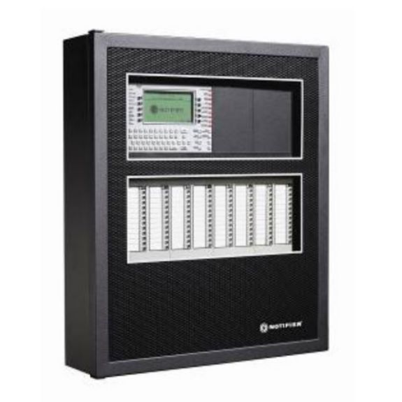
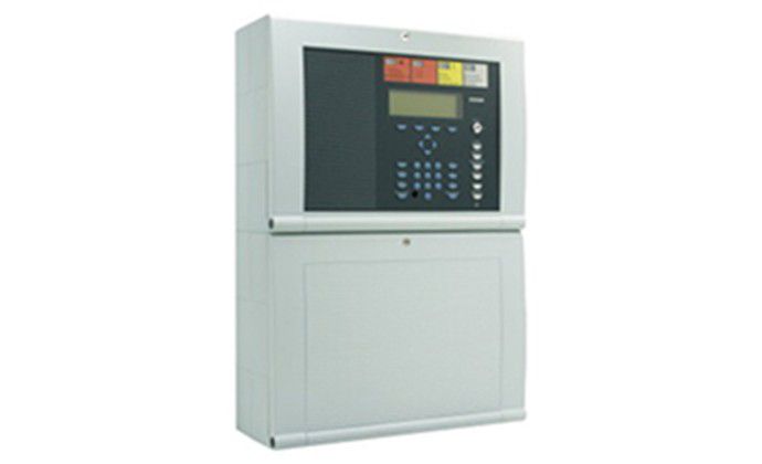
Addressable Fire Detection Panel

medium 643 / 643 models (Inspector)

An addressable panel polls every detector by its own address and reports the exact device in alarm, instead of just the zone a conventional panel would report — the difference that lets the crew go straight to the right compartment.

Read more — Addressable Fire Detection Panel explained

What makes an addressable panel different

A conventional zone panel only tells the crew which loop or zone has raised an alarm; an addressable panel polls each detector, manual call point and interface unit by its individual address and reports back exactly which device triggered. On a ship with hundreds of spaces sharing a handful of zones under the older approach, that difference is what lets the duty engineer walk straight to the cabin or void space in alarm instead of searching an entire fire zone.

Addressable fire detection panel arrangement
Arrangement of an addressable fire detection panel with its standby battery, the ring addressable loop carrying individually addressed detectors and an isolator module, a branch to the sounder and bell circuit, and a link to the repeater panel on the bridge.

Main components

Control panel / CPU

Polls the loop continuously, holds the cause-and-effect programming and drives the alarm, fault and disablement indications required at the panel and at repeat panels on the bridge.

Loop wiring

A closed-loop (class A) cable run from the panel out through the detectors and back, so a single cable break or short still leaves every device reachable from the other direction.

Addressable detectors and call points

Smoke, heat or multi-sensor detectors and manual call points, each holding its own address so the panel can identify it individually and, on modern systems, report drift in its sensitivity before it reaches an alarm threshold.

Interface (monitor/control) modules

Address-carrying modules that bring conventional devices, dampers, fan shutdowns or door releases onto the addressable loop so the panel can both monitor and command them.

Selection / Sizing

  • Loop capacity and the number of loops needed for the vessel's device count, with spare capacity for later additions rather than a loop run at its limit.
  • Cause-and-effect matrix: which detector triggers which fan shutdown, damper closure or door release, defined before the system is programmed rather than left to the installer.
  • Repeat panel locations, typically the bridge and a fire control station, so the alarm is visible where the crew is actually standing.
  • Compatibility of detector heads with the space they cover — heat detectors in galleys and engine rooms where smoke detectors would false-alarm on cooking fumes or exhaust.

Regulations / Class

SOLAS Ch. II-2 requires fixed fire detection in accommodation, service and machinery spaces on most cargo ships and all passenger ships, with the system type and detector spacing following the FSS Code. Class surveys include functional testing of detector response, cause-and-effect actions and the fire control station's fire control plan, and the panel's battery back-up must sustain the system for a defined period on loss of main power.

Typical faults

FaultCauseConsequence
Nuisance alarms from galley or engine roomSmoke detectors installed where heat detectors belongCrew starts disabling zones, defeating the system's purpose
Ground fault on the loopMoisture ingress at a detector base or glandPanel loses the ability to isolate the true fault location
Detector drift undetectedDust or ageing sensor not flagged for cleaningDetector eventually fails to alarm within its rated response time
Battery back-up failureStandby batteries not load-tested at surveySystem has no protection on loss of main supply

What to look for in a supplier

  • Type approval for the panel and detector range from a recognised classification society, not just a national fire standard.
  • Documented cause-and-effect programming delivered with the system, matched to the actual ship, not a generic template.
  • Availability of compatible detector heads and interface modules years after installation, since addressable loops are rarely mixed-brand.
  • A commissioning test report showing every device address verified against the as-built drawing.

An addressable panel is only as good as its cause-and-effect table — a detector that correctly identifies itself is worthless if nobody checked that it still shuts the right fan down.

Inspector Mode Show All 643 / 643 with inspector value

72 manufacturers · 643 models

Consilium Marine

96
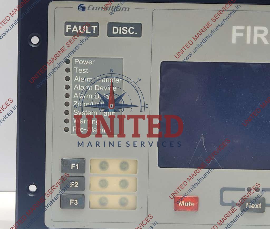
Consilium Salwico CS4000
Salwico CS4000
up to 2000 points · Fire Suppression / Detection · addressable fire detection panel
Type
addressable
Loops
8
Points per loop
250
Solas
ja
Common Failures & Inspection Points
  • Sensor ageing, poisoning, contamination or dirt causes drift, slow response, false alarms or failed tests
  • Power, battery, wiring or communication faults cause device-failure alarms or loss of indication
  • Water ingress, corrosion or impact damage causes intermittent operation or failed controls
  • Blocked sampling paths or obstructed detector exposure delays response or prevents correct detection
  • Incorrect calibration, configuration or detector type causes misleading readings or nuisance alarms
Service: Inspect sensors, sample paths or detector openings, wiring, power, mounting and alarm interfaces. Perform bump tests, functional tests or calibration using the approved method for the device type. Review alarm history and confirm remote indications or shutdown interfaces. Refer to the manufacturer documentation for the exact figure for calibration and alarm criteria.
Spare Parts: Carry detector heads or sensor cartridges, filters, sampling parts, batteries or chargers, fuses, calibration accessories and approved test consumables.
Strengths
  • High point capacity (up to 2 000 detectors) on a single panel
  • Modular loop cards allow selective isolation and easy expansion
  • Built‑in diagnostics alert operators to loop faults, card failures or detector issues
  • Fully SOLAS compliant – suitable for passenger and cargo vessels
  • Standard weekly panel test routine simplifies regulatory compliance
Weaknesses
  • Reported susceptibility to loop‑card failure and panel display malfunction
  • Detector base corrosion can require premature replacement in humid marine environments
  • Limited to eight loops; very large ships may need multiple panels
  • Requires regular detector replacement (5–8 years) to maintain reliability
  • Older user interface compared with newer networked fire‑safety systems
Typical Vessels: Passenger ferryCruise shipRo‑Ro vesselOffshore supply vesselContainer shipTanker
Certifications: SOLAS
Decision Guide: Choose if you need a proven, addressable fire detection system with up to 2 000 points, modular loop cards for easy maintenance and full SOLAS compliance on medium‑size vessels. Avoid if the vessel requires more than eight loops, integration with advanced digital bridge systems, or the latest IoT‑based sensor networks.
Use Cases: Machinery, cargo, accommodation, enclosed-space and personal safety monitoring.
Salwico CS5000
up to 4000 points · Fire Suppression / Detection · addressable fire detection panel
Type
addressable
Loops
16
Points per loop
250
Solas
ja
Networked
ja
Common Failures & Inspection Points
  • Sensor ageing, poisoning, contamination or dirt causes drift, slow response, false alarms or failed tests
  • Power, battery, wiring or communication faults cause device-failure alarms or loss of indication
  • Water ingress, corrosion or impact damage causes intermittent operation or failed controls
  • Blocked sampling paths or obstructed detector exposure delays response or prevents correct detection
  • Incorrect calibration, configuration or detector type causes misleading readings or nuisance alarms
Service: Inspect sensors, sample paths or detector openings, wiring, power, mounting and alarm interfaces. Perform bump tests, functional tests or calibration using the approved method for the device type. Review alarm history and confirm remote indications or shutdown interfaces. Refer to the manufacturer documentation for the exact figure for calibration and alarm criteria.
Spare Parts: Carry detector heads or sensor cartridges, filters, sampling parts, batteries or chargers, fuses, calibration accessories and approved test consumables.
Strengths
  • High point capacity (up to 4,000 detectors) suitable for large vessels
  • SOLAS (IMO D-2) compliant – meets mandatory safety regulations
  • Networked architecture enables remote monitoring and diagnostics from the ship’s integrated bridge system
  • Addressable detection allows precise location of alarms and fault isolation
  • Supports annual full‑system test procedures built into software
Weaknesses
  • Reliance on network communication; failures can disable alarm propagation
  • Software crashes have been reported, requiring periodic firmware updates
  • Detector contamination can cause false alarms or loss of detection if not cleaned regularly
  • Power supply failure may affect the whole panel unless redundant supplies are installed
  • Installation and commissioning are more complex than analog panels, needing trained personnel
Typical Vessels: TankerContainer shipBulk carrierCruise linerOffshore support vessel
Certifications: IMO D-2 (SOLAS) approval
Decision Guide: Choose if: you need a high‑capacity, SOLAS‑compliant fire detection system with remote diagnostics and precise point‑by‑point alarm location. Avoid if: your vessel lacks the IT infrastructure for networked panels, you prefer a simpler analog solution, or you are highly sensitive to software reliability issues.
Use Cases: Machinery, cargo, accommodation, enclosed-space and personal safety monitoring.
Consilium Salwico CS4000 Panel unverified
Equipment Type
fire_detection_panel
Series
Salwico
Common Failures & Inspection Points
  • Detector contamination or sensor aging caused by dust, grease, moisture or long service, resulting in false alarms, slow response or fault indication
  • Loop or cable fault caused by damaged wiring, loose terminals or earth leakage, resulting in missing devices, intermittent faults or a loop alarm
  • Addressing or configuration error caused by replacement or software changes, resulting in incorrect device identification or unavailable zones
  • Power-supply or backup-battery deterioration caused by charger faults, aged batteries or wiring problems, resulting in power alarms or reduced standby capability
  • Panel, relay or communication failure caused by electronics faults, resulting in missing alarms, failed outputs or loss of connection to other safety systems
Service: Inspect detectors, call points, panels, loops, power supplies and interfaces according to the approved fire-system test plan. Keep sensing openings clean and protect devices from paint, steam and dust during maintenance. Function-test alarms, zone identification, sounders and required output relays using approved test tools and procedures. Check backup batteries and power-failure indications and record any isolated zone or disabled device. Restore all bypasses and isolations after work. Refer to the manufacturer documentation for the exact figure for test frequencies, detector limits and replacement procedures.
Spare Parts: Keep approved detector heads, bases, manual-call-point elements, loop modules, fuses, batteries, relays and selected panel components compatible with the installed system. Replacement devices must preserve addressing and type approval. Maintain approved test tools and detector-specific service accessories.
Use Cases: Automatic and manual fire detection in machinery spaces, accommodation, cargo areas and other protected shipboard spaces.
Salwico panel — addressable
Consilium Salwico SW4000 Panel unverified
Equipment Type
fire_detection_panel
Series
Salwico
Common Failures & Inspection Points
  • Detector contamination or sensor aging caused by dust, grease, moisture or long service, resulting in false alarms, slow response or fault indication
  • Loop or cable fault caused by damaged wiring, loose terminals or earth leakage, resulting in missing devices, intermittent faults or a loop alarm
  • Addressing or configuration error caused by replacement or software changes, resulting in incorrect device identification or unavailable zones
  • Power-supply or backup-battery deterioration caused by charger faults, aged batteries or wiring problems, resulting in power alarms or reduced standby capability
  • Panel, relay or communication failure caused by electronics faults, resulting in missing alarms, failed outputs or loss of connection to other safety systems
Service: Inspect detectors, call points, panels, loops, power supplies and interfaces according to the approved fire-system test plan. Keep sensing openings clean and protect devices from paint, steam and dust during maintenance. Function-test alarms, zone identification, sounders and required output relays using approved test tools and procedures. Check backup batteries and power-failure indications and record any isolated zone or disabled device. Restore all bypasses and isolations after work. Refer to the manufacturer documentation for the exact figure for test frequencies, detector limits and replacement procedures.
Spare Parts: Keep approved detector heads, bases, manual-call-point elements, loop modules, fuses, batteries, relays and selected panel components compatible with the installed system. Replacement devices must preserve addressing and type approval. Maintain approved test tools and detector-specific service accessories.
Use Cases: Automatic and manual fire detection in machinery spaces, accommodation, cargo areas and other protected shipboard spaces.
Salwico panel — conventional
Consilium Salwico N4000 Panel unverified
Equipment Type
fire_detection_panel
Series
Salwico
Common Failures & Inspection Points
  • Detector contamination or sensor aging caused by dust, grease, moisture or long service, resulting in false alarms, slow response or fault indication
  • Loop or cable fault caused by damaged wiring, loose terminals or earth leakage, resulting in missing devices, intermittent faults or a loop alarm
  • Addressing or configuration error caused by replacement or software changes, resulting in incorrect device identification or unavailable zones
  • Power-supply or backup-battery deterioration caused by charger faults, aged batteries or wiring problems, resulting in power alarms or reduced standby capability
  • Panel, relay or communication failure caused by electronics faults, resulting in missing alarms, failed outputs or loss of connection to other safety systems
Service: Inspect detectors, call points, panels, loops, power supplies and interfaces according to the approved fire-system test plan. Keep sensing openings clean and protect devices from paint, steam and dust during maintenance. Function-test alarms, zone identification, sounders and required output relays using approved test tools and procedures. Check backup batteries and power-failure indications and record any isolated zone or disabled device. Restore all bypasses and isolations after work. Refer to the manufacturer documentation for the exact figure for test frequencies, detector limits and replacement procedures.
Spare Parts: Keep approved detector heads, bases, manual-call-point elements, loop modules, fuses, batteries, relays and selected panel components compatible with the installed system. Replacement devices must preserve addressing and type approval. Maintain approved test tools and detector-specific service accessories.
Use Cases: Automatic and manual fire detection in machinery spaces, accommodation, cargo areas and other protected shipboard spaces.
Salwico panel — networked
Salwico CS4000 32-Zone unverified
Zones
32
Addressable
ja
IMO Compliant
ja
Common Failures & Inspection Points
  • Detector contamination or sensor aging caused by dust, grease, moisture or long service, resulting in false alarms, slow response or fault indication
  • Loop or cable fault caused by damaged wiring, loose terminals or earth leakage, resulting in missing devices, intermittent faults or a loop alarm
  • Addressing or configuration error caused by replacement or software changes, resulting in incorrect device identification or unavailable zones
  • Power-supply or backup-battery deterioration caused by charger faults, aged batteries or wiring problems, resulting in power alarms or reduced standby capability
  • Panel, relay or communication failure caused by electronics faults, resulting in missing alarms, failed outputs or loss of connection to other safety systems
Service: Inspect detectors, call points, panels, loops, power supplies and interfaces according to the approved fire-system test plan. Keep sensing openings clean and protect devices from paint, steam and dust during maintenance. Function-test alarms, zone identification, sounders and required output relays using approved test tools and procedures. Check backup batteries and power-failure indications and record any isolated zone or disabled device. Restore all bypasses and isolations after work. Refer to the manufacturer documentation for the exact figure for test frequencies, detector limits and replacement procedures.
Spare Parts: Keep approved detector heads, bases, manual-call-point elements, loop modules, fuses, batteries, relays and selected panel components compatible with the installed system. Replacement devices must preserve addressing and type approval. Maintain approved test tools and detector-specific service accessories.
Use Cases: Automatic and manual fire detection in machinery spaces, accommodation, cargo areas and other protected shipboard spaces.
Salwico CS4000 64-Zone unverified
Zones
64
Addressable
ja
IMO Compliant
ja
Common Failures & Inspection Points
  • Detector contamination or sensor aging caused by dust, grease, moisture or long service, resulting in false alarms, slow response or fault indication
  • Loop or cable fault caused by damaged wiring, loose terminals or earth leakage, resulting in missing devices, intermittent faults or a loop alarm
  • Addressing or configuration error caused by replacement or software changes, resulting in incorrect device identification or unavailable zones
  • Power-supply or backup-battery deterioration caused by charger faults, aged batteries or wiring problems, resulting in power alarms or reduced standby capability
  • Panel, relay or communication failure caused by electronics faults, resulting in missing alarms, failed outputs or loss of connection to other safety systems
Service: Inspect detectors, call points, panels, loops, power supplies and interfaces according to the approved fire-system test plan. Keep sensing openings clean and protect devices from paint, steam and dust during maintenance. Function-test alarms, zone identification, sounders and required output relays using approved test tools and procedures. Check backup batteries and power-failure indications and record any isolated zone or disabled device. Restore all bypasses and isolations after work. Refer to the manufacturer documentation for the exact figure for test frequencies, detector limits and replacement procedures.
Spare Parts: Keep approved detector heads, bases, manual-call-point elements, loop modules, fuses, batteries, relays and selected panel components compatible with the installed system. Replacement devices must preserve addressing and type approval. Maintain approved test tools and detector-specific service accessories.
Use Cases: Automatic and manual fire detection in machinery spaces, accommodation, cargo areas and other protected shipboard spaces.
Salwico CS4000 128-Zone unverified
Zones
128
Addressable
ja
IMO Compliant
ja
Common Failures & Inspection Points
  • Detector contamination or sensor aging caused by dust, grease, moisture or long service, resulting in false alarms, slow response or fault indication
  • Loop or cable fault caused by damaged wiring, loose terminals or earth leakage, resulting in missing devices, intermittent faults or a loop alarm
  • Addressing or configuration error caused by replacement or software changes, resulting in incorrect device identification or unavailable zones
  • Power-supply or backup-battery deterioration caused by charger faults, aged batteries or wiring problems, resulting in power alarms or reduced standby capability
  • Panel, relay or communication failure caused by electronics faults, resulting in missing alarms, failed outputs or loss of connection to other safety systems
Service: Inspect detectors, call points, panels, loops, power supplies and interfaces according to the approved fire-system test plan. Keep sensing openings clean and protect devices from paint, steam and dust during maintenance. Function-test alarms, zone identification, sounders and required output relays using approved test tools and procedures. Check backup batteries and power-failure indications and record any isolated zone or disabled device. Restore all bypasses and isolations after work. Refer to the manufacturer documentation for the exact figure for test frequencies, detector limits and replacement procedures.
Spare Parts: Keep approved detector heads, bases, manual-call-point elements, loop modules, fuses, batteries, relays and selected panel components compatible with the installed system. Replacement devices must preserve addressing and type approval. Maintain approved test tools and detector-specific service accessories.
Use Cases: Automatic and manual fire detection in machinery spaces, accommodation, cargo areas and other protected shipboard spaces.
Salwico CS4000 256-Zone unverified
Zones
256
Addressable
ja
IMO Compliant
ja
Common Failures & Inspection Points
  • Detector contamination or sensor aging caused by dust, grease, moisture or long service, resulting in false alarms, slow response or fault indication
  • Loop or cable fault caused by damaged wiring, loose terminals or earth leakage, resulting in missing devices, intermittent faults or a loop alarm
  • Addressing or configuration error caused by replacement or software changes, resulting in incorrect device identification or unavailable zones
  • Power-supply or backup-battery deterioration caused by charger faults, aged batteries or wiring problems, resulting in power alarms or reduced standby capability
  • Panel, relay or communication failure caused by electronics faults, resulting in missing alarms, failed outputs or loss of connection to other safety systems
Service: Inspect detectors, call points, panels, loops, power supplies and interfaces according to the approved fire-system test plan. Keep sensing openings clean and protect devices from paint, steam and dust during maintenance. Function-test alarms, zone identification, sounders and required output relays using approved test tools and procedures. Check backup batteries and power-failure indications and record any isolated zone or disabled device. Restore all bypasses and isolations after work. Refer to the manufacturer documentation for the exact figure for test frequencies, detector limits and replacement procedures.
Spare Parts: Keep approved detector heads, bases, manual-call-point elements, loop modules, fuses, batteries, relays and selected panel components compatible with the installed system. Replacement devices must preserve addressing and type approval. Maintain approved test tools and detector-specific service accessories.
Use Cases: Automatic and manual fire detection in machinery spaces, accommodation, cargo areas and other protected shipboard spaces.
Salwico CS4000 512-Zone unverified
Zones
512
Addressable
ja
IMO Compliant
ja
Common Failures & Inspection Points
  • Detector contamination or sensor aging caused by dust, grease, moisture or long service, resulting in false alarms, slow response or fault indication
  • Loop or cable fault caused by damaged wiring, loose terminals or earth leakage, resulting in missing devices, intermittent faults or a loop alarm
  • Addressing or configuration error caused by replacement or software changes, resulting in incorrect device identification or unavailable zones
  • Power-supply or backup-battery deterioration caused by charger faults, aged batteries or wiring problems, resulting in power alarms or reduced standby capability
  • Panel, relay or communication failure caused by electronics faults, resulting in missing alarms, failed outputs or loss of connection to other safety systems
Service: Inspect detectors, call points, panels, loops, power supplies and interfaces according to the approved fire-system test plan. Keep sensing openings clean and protect devices from paint, steam and dust during maintenance. Function-test alarms, zone identification, sounders and required output relays using approved test tools and procedures. Check backup batteries and power-failure indications and record any isolated zone or disabled device. Restore all bypasses and isolations after work. Refer to the manufacturer documentation for the exact figure for test frequencies, detector limits and replacement procedures.
Spare Parts: Keep approved detector heads, bases, manual-call-point elements, loop modules, fuses, batteries, relays and selected panel components compatible with the installed system. Replacement devices must preserve addressing and type approval. Maintain approved test tools and detector-specific service accessories.
Use Cases: Automatic and manual fire detection in machinery spaces, accommodation, cargo areas and other protected shipboard spaces.
Salwico CS5000 32-Zone unverified
Zones
32
Addressable
ja
IMO Compliant
ja
Common Failures & Inspection Points
  • Detector contamination or sensor aging caused by dust, grease, moisture or long service, resulting in false alarms, slow response or fault indication
  • Loop or cable fault caused by damaged wiring, loose terminals or earth leakage, resulting in missing devices, intermittent faults or a loop alarm
  • Addressing or configuration error caused by replacement or software changes, resulting in incorrect device identification or unavailable zones
  • Power-supply or backup-battery deterioration caused by charger faults, aged batteries or wiring problems, resulting in power alarms or reduced standby capability
  • Panel, relay or communication failure caused by electronics faults, resulting in missing alarms, failed outputs or loss of connection to other safety systems
Service: Inspect detectors, call points, panels, loops, power supplies and interfaces according to the approved fire-system test plan. Keep sensing openings clean and protect devices from paint, steam and dust during maintenance. Function-test alarms, zone identification, sounders and required output relays using approved test tools and procedures. Check backup batteries and power-failure indications and record any isolated zone or disabled device. Restore all bypasses and isolations after work. Refer to the manufacturer documentation for the exact figure for test frequencies, detector limits and replacement procedures.
Spare Parts: Keep approved detector heads, bases, manual-call-point elements, loop modules, fuses, batteries, relays and selected panel components compatible with the installed system. Replacement devices must preserve addressing and type approval. Maintain approved test tools and detector-specific service accessories.
Use Cases: Automatic and manual fire detection in machinery spaces, accommodation, cargo areas and other protected shipboard spaces.
Salwico CS5000 64-Zone unverified
Zones
64
Addressable
ja
IMO Compliant
ja
Common Failures & Inspection Points
  • Detector contamination or sensor aging caused by dust, grease, moisture or long service, resulting in false alarms, slow response or fault indication
  • Loop or cable fault caused by damaged wiring, loose terminals or earth leakage, resulting in missing devices, intermittent faults or a loop alarm
  • Addressing or configuration error caused by replacement or software changes, resulting in incorrect device identification or unavailable zones
  • Power-supply or backup-battery deterioration caused by charger faults, aged batteries or wiring problems, resulting in power alarms or reduced standby capability
  • Panel, relay or communication failure caused by electronics faults, resulting in missing alarms, failed outputs or loss of connection to other safety systems
Service: Inspect detectors, call points, panels, loops, power supplies and interfaces according to the approved fire-system test plan. Keep sensing openings clean and protect devices from paint, steam and dust during maintenance. Function-test alarms, zone identification, sounders and required output relays using approved test tools and procedures. Check backup batteries and power-failure indications and record any isolated zone or disabled device. Restore all bypasses and isolations after work. Refer to the manufacturer documentation for the exact figure for test frequencies, detector limits and replacement procedures.
Spare Parts: Keep approved detector heads, bases, manual-call-point elements, loop modules, fuses, batteries, relays and selected panel components compatible with the installed system. Replacement devices must preserve addressing and type approval. Maintain approved test tools and detector-specific service accessories.
Use Cases: Automatic and manual fire detection in machinery spaces, accommodation, cargo areas and other protected shipboard spaces.
Salwico CS5000 128-Zone unverified
Zones
128
Addressable
ja
IMO Compliant
ja
Common Failures & Inspection Points
  • Detector contamination or sensor aging caused by dust, grease, moisture or long service, resulting in false alarms, slow response or fault indication
  • Loop or cable fault caused by damaged wiring, loose terminals or earth leakage, resulting in missing devices, intermittent faults or a loop alarm
  • Addressing or configuration error caused by replacement or software changes, resulting in incorrect device identification or unavailable zones
  • Power-supply or backup-battery deterioration caused by charger faults, aged batteries or wiring problems, resulting in power alarms or reduced standby capability
  • Panel, relay or communication failure caused by electronics faults, resulting in missing alarms, failed outputs or loss of connection to other safety systems
Service: Inspect detectors, call points, panels, loops, power supplies and interfaces according to the approved fire-system test plan. Keep sensing openings clean and protect devices from paint, steam and dust during maintenance. Function-test alarms, zone identification, sounders and required output relays using approved test tools and procedures. Check backup batteries and power-failure indications and record any isolated zone or disabled device. Restore all bypasses and isolations after work. Refer to the manufacturer documentation for the exact figure for test frequencies, detector limits and replacement procedures.
Spare Parts: Keep approved detector heads, bases, manual-call-point elements, loop modules, fuses, batteries, relays and selected panel components compatible with the installed system. Replacement devices must preserve addressing and type approval. Maintain approved test tools and detector-specific service accessories.
Use Cases: Automatic and manual fire detection in machinery spaces, accommodation, cargo areas and other protected shipboard spaces.
Salwico CS5000 256-Zone unverified
Zones
256
Addressable
ja
IMO Compliant
ja
Common Failures & Inspection Points
  • Detector contamination or sensor aging caused by dust, grease, moisture or long service, resulting in false alarms, slow response or fault indication
  • Loop or cable fault caused by damaged wiring, loose terminals or earth leakage, resulting in missing devices, intermittent faults or a loop alarm
  • Addressing or configuration error caused by replacement or software changes, resulting in incorrect device identification or unavailable zones
  • Power-supply or backup-battery deterioration caused by charger faults, aged batteries or wiring problems, resulting in power alarms or reduced standby capability
  • Panel, relay or communication failure caused by electronics faults, resulting in missing alarms, failed outputs or loss of connection to other safety systems
Service: Inspect detectors, call points, panels, loops, power supplies and interfaces according to the approved fire-system test plan. Keep sensing openings clean and protect devices from paint, steam and dust during maintenance. Function-test alarms, zone identification, sounders and required output relays using approved test tools and procedures. Check backup batteries and power-failure indications and record any isolated zone or disabled device. Restore all bypasses and isolations after work. Refer to the manufacturer documentation for the exact figure for test frequencies, detector limits and replacement procedures.
Spare Parts: Keep approved detector heads, bases, manual-call-point elements, loop modules, fuses, batteries, relays and selected panel components compatible with the installed system. Replacement devices must preserve addressing and type approval. Maintain approved test tools and detector-specific service accessories.
Use Cases: Automatic and manual fire detection in machinery spaces, accommodation, cargo areas and other protected shipboard spaces.
Salwico CS5000 512-Zone unverified
Zones
512
Addressable
ja
IMO Compliant
ja
Common Failures & Inspection Points
  • Detector contamination or sensor aging caused by dust, grease, moisture or long service, resulting in false alarms, slow response or fault indication
  • Loop or cable fault caused by damaged wiring, loose terminals or earth leakage, resulting in missing devices, intermittent faults or a loop alarm
  • Addressing or configuration error caused by replacement or software changes, resulting in incorrect device identification or unavailable zones
  • Power-supply or backup-battery deterioration caused by charger faults, aged batteries or wiring problems, resulting in power alarms or reduced standby capability
  • Panel, relay or communication failure caused by electronics faults, resulting in missing alarms, failed outputs or loss of connection to other safety systems
Service: Inspect detectors, call points, panels, loops, power supplies and interfaces according to the approved fire-system test plan. Keep sensing openings clean and protect devices from paint, steam and dust during maintenance. Function-test alarms, zone identification, sounders and required output relays using approved test tools and procedures. Check backup batteries and power-failure indications and record any isolated zone or disabled device. Restore all bypasses and isolations after work. Refer to the manufacturer documentation for the exact figure for test frequencies, detector limits and replacement procedures.
Spare Parts: Keep approved detector heads, bases, manual-call-point elements, loop modules, fuses, batteries, relays and selected panel components compatible with the installed system. Replacement devices must preserve addressing and type approval. Maintain approved test tools and detector-specific service accessories.
Use Cases: Automatic and manual fire detection in machinery spaces, accommodation, cargo areas and other protected shipboard spaces.
Salwico CS5100 32-Zone unverified
Zones
32
Addressable
ja
IMO Compliant
ja
Common Failures & Inspection Points
  • Detector contamination or sensor aging caused by dust, grease, moisture or long service, resulting in false alarms, slow response or fault indication
  • Loop or cable fault caused by damaged wiring, loose terminals or earth leakage, resulting in missing devices, intermittent faults or a loop alarm
  • Addressing or configuration error caused by replacement or software changes, resulting in incorrect device identification or unavailable zones
  • Power-supply or backup-battery deterioration caused by charger faults, aged batteries or wiring problems, resulting in power alarms or reduced standby capability
  • Panel, relay or communication failure caused by electronics faults, resulting in missing alarms, failed outputs or loss of connection to other safety systems
Service: Inspect detectors, call points, panels, loops, power supplies and interfaces according to the approved fire-system test plan. Keep sensing openings clean and protect devices from paint, steam and dust during maintenance. Function-test alarms, zone identification, sounders and required output relays using approved test tools and procedures. Check backup batteries and power-failure indications and record any isolated zone or disabled device. Restore all bypasses and isolations after work. Refer to the manufacturer documentation for the exact figure for test frequencies, detector limits and replacement procedures.
Spare Parts: Keep approved detector heads, bases, manual-call-point elements, loop modules, fuses, batteries, relays and selected panel components compatible with the installed system. Replacement devices must preserve addressing and type approval. Maintain approved test tools and detector-specific service accessories.
Use Cases: Automatic and manual fire detection in machinery spaces, accommodation, cargo areas and other protected shipboard spaces.
Salwico CS5100 64-Zone unverified
Zones
64
Addressable
ja
IMO Compliant
ja
Common Failures & Inspection Points
  • Detector contamination or sensor aging caused by dust, grease, moisture or long service, resulting in false alarms, slow response or fault indication
  • Loop or cable fault caused by damaged wiring, loose terminals or earth leakage, resulting in missing devices, intermittent faults or a loop alarm
  • Addressing or configuration error caused by replacement or software changes, resulting in incorrect device identification or unavailable zones
  • Power-supply or backup-battery deterioration caused by charger faults, aged batteries or wiring problems, resulting in power alarms or reduced standby capability
  • Panel, relay or communication failure caused by electronics faults, resulting in missing alarms, failed outputs or loss of connection to other safety systems
Service: Inspect detectors, call points, panels, loops, power supplies and interfaces according to the approved fire-system test plan. Keep sensing openings clean and protect devices from paint, steam and dust during maintenance. Function-test alarms, zone identification, sounders and required output relays using approved test tools and procedures. Check backup batteries and power-failure indications and record any isolated zone or disabled device. Restore all bypasses and isolations after work. Refer to the manufacturer documentation for the exact figure for test frequencies, detector limits and replacement procedures.
Spare Parts: Keep approved detector heads, bases, manual-call-point elements, loop modules, fuses, batteries, relays and selected panel components compatible with the installed system. Replacement devices must preserve addressing and type approval. Maintain approved test tools and detector-specific service accessories.
Use Cases: Automatic and manual fire detection in machinery spaces, accommodation, cargo areas and other protected shipboard spaces.
Salwico CS5100 128-Zone unverified
Zones
128
Addressable
ja
IMO Compliant
ja
Common Failures & Inspection Points
  • Detector contamination or sensor aging caused by dust, grease, moisture or long service, resulting in false alarms, slow response or fault indication
  • Loop or cable fault caused by damaged wiring, loose terminals or earth leakage, resulting in missing devices, intermittent faults or a loop alarm
  • Addressing or configuration error caused by replacement or software changes, resulting in incorrect device identification or unavailable zones
  • Power-supply or backup-battery deterioration caused by charger faults, aged batteries or wiring problems, resulting in power alarms or reduced standby capability
  • Panel, relay or communication failure caused by electronics faults, resulting in missing alarms, failed outputs or loss of connection to other safety systems
Service: Inspect detectors, call points, panels, loops, power supplies and interfaces according to the approved fire-system test plan. Keep sensing openings clean and protect devices from paint, steam and dust during maintenance. Function-test alarms, zone identification, sounders and required output relays using approved test tools and procedures. Check backup batteries and power-failure indications and record any isolated zone or disabled device. Restore all bypasses and isolations after work. Refer to the manufacturer documentation for the exact figure for test frequencies, detector limits and replacement procedures.
Spare Parts: Keep approved detector heads, bases, manual-call-point elements, loop modules, fuses, batteries, relays and selected panel components compatible with the installed system. Replacement devices must preserve addressing and type approval. Maintain approved test tools and detector-specific service accessories.
Use Cases: Automatic and manual fire detection in machinery spaces, accommodation, cargo areas and other protected shipboard spaces.
Salwico CS5100 256-Zone unverified
Zones
256
Addressable
ja
IMO Compliant
ja
Common Failures & Inspection Points
  • Detector contamination or sensor aging caused by dust, grease, moisture or long service, resulting in false alarms, slow response or fault indication
  • Loop or cable fault caused by damaged wiring, loose terminals or earth leakage, resulting in missing devices, intermittent faults or a loop alarm
  • Addressing or configuration error caused by replacement or software changes, resulting in incorrect device identification or unavailable zones
  • Power-supply or backup-battery deterioration caused by charger faults, aged batteries or wiring problems, resulting in power alarms or reduced standby capability
  • Panel, relay or communication failure caused by electronics faults, resulting in missing alarms, failed outputs or loss of connection to other safety systems
Service: Inspect detectors, call points, panels, loops, power supplies and interfaces according to the approved fire-system test plan. Keep sensing openings clean and protect devices from paint, steam and dust during maintenance. Function-test alarms, zone identification, sounders and required output relays using approved test tools and procedures. Check backup batteries and power-failure indications and record any isolated zone or disabled device. Restore all bypasses and isolations after work. Refer to the manufacturer documentation for the exact figure for test frequencies, detector limits and replacement procedures.
Spare Parts: Keep approved detector heads, bases, manual-call-point elements, loop modules, fuses, batteries, relays and selected panel components compatible with the installed system. Replacement devices must preserve addressing and type approval. Maintain approved test tools and detector-specific service accessories.
Use Cases: Automatic and manual fire detection in machinery spaces, accommodation, cargo areas and other protected shipboard spaces.
Salwico CS5100 512-Zone unverified
Zones
512
Addressable
ja
IMO Compliant
ja
Common Failures & Inspection Points
  • Detector contamination or sensor aging caused by dust, grease, moisture or long service, resulting in false alarms, slow response or fault indication
  • Loop or cable fault caused by damaged wiring, loose terminals or earth leakage, resulting in missing devices, intermittent faults or a loop alarm
  • Addressing or configuration error caused by replacement or software changes, resulting in incorrect device identification or unavailable zones
  • Power-supply or backup-battery deterioration caused by charger faults, aged batteries or wiring problems, resulting in power alarms or reduced standby capability
  • Panel, relay or communication failure caused by electronics faults, resulting in missing alarms, failed outputs or loss of connection to other safety systems
Service: Inspect detectors, call points, panels, loops, power supplies and interfaces according to the approved fire-system test plan. Keep sensing openings clean and protect devices from paint, steam and dust during maintenance. Function-test alarms, zone identification, sounders and required output relays using approved test tools and procedures. Check backup batteries and power-failure indications and record any isolated zone or disabled device. Restore all bypasses and isolations after work. Refer to the manufacturer documentation for the exact figure for test frequencies, detector limits and replacement procedures.
Spare Parts: Keep approved detector heads, bases, manual-call-point elements, loop modules, fuses, batteries, relays and selected panel components compatible with the installed system. Replacement devices must preserve addressing and type approval. Maintain approved test tools and detector-specific service accessories.
Use Cases: Automatic and manual fire detection in machinery spaces, accommodation, cargo areas and other protected shipboard spaces.
Salwico A100 8-Zone unverified
Zones
8
IMO Compliant
ja
Common Failures & Inspection Points
  • Loop or zone wiring faults cause open-circuit, short-circuit or missing-device indications
  • Backup-battery or power-supply faults cause charger alarms, reduced standby capability or panel reset
  • Detector addressing or configuration errors cause incorrect alarm location or missing devices
  • Display, processor or communication faults cause frozen indications or loss of remote repeater information
  • Relay or output-interface faults prevent required remote alarms, fan stops or fire-safety actions
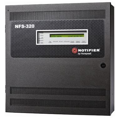
Service: Review panel faults, loop or zone status, batteries, charger, repeaters and output interfaces. Test representative detectors and verify correct location text and remote alarm transmission under the approved fire-testing procedure. Maintain controlled backups of address and cause-and-effect configuration where applicable. Refer to the manufacturer and fire-control documentation for the exact figure for battery, loop and test limits.
Spare Parts: Carry compatible detector bases or loop modules, fuses, backup batteries, power supplies, relays and supported panel or repeater modules.
Use Cases: Central fire detection and alarm supervision on commercial, passenger and offshore vessels.
Salwico A100 16-Zone unverified
Zones
16
IMO Compliant
ja
Common Failures & Inspection Points
  • Loop or zone wiring faults cause open-circuit, short-circuit or missing-device indications
  • Backup-battery or power-supply faults cause charger alarms, reduced standby capability or panel reset
  • Detector addressing or configuration errors cause incorrect alarm location or missing devices
  • Display, processor or communication faults cause frozen indications or loss of remote repeater information
  • Relay or output-interface faults prevent required remote alarms, fan stops or fire-safety actions
Service: Review panel faults, loop or zone status, batteries, charger, repeaters and output interfaces. Test representative detectors and verify correct location text and remote alarm transmission under the approved fire-testing procedure. Maintain controlled backups of address and cause-and-effect configuration where applicable. Refer to the manufacturer and fire-control documentation for the exact figure for battery, loop and test limits.
Spare Parts: Carry compatible detector bases or loop modules, fuses, backup batteries, power supplies, relays and supported panel or repeater modules.
Use Cases: Central fire detection and alarm supervision on commercial, passenger and offshore vessels.
Salwico A100 32-Zone unverified
Zones
32
IMO Compliant
ja
Common Failures & Inspection Points
  • Loop or zone wiring faults cause open-circuit, short-circuit or missing-device indications
  • Backup-battery or power-supply faults cause charger alarms, reduced standby capability or panel reset
  • Detector addressing or configuration errors cause incorrect alarm location or missing devices
  • Display, processor or communication faults cause frozen indications or loss of remote repeater information
  • Relay or output-interface faults prevent required remote alarms, fan stops or fire-safety actions
Service: Review panel faults, loop or zone status, batteries, charger, repeaters and output interfaces. Test representative detectors and verify correct location text and remote alarm transmission under the approved fire-testing procedure. Maintain controlled backups of address and cause-and-effect configuration where applicable. Refer to the manufacturer and fire-control documentation for the exact figure for battery, loop and test limits.
Spare Parts: Carry compatible detector bases or loop modules, fuses, backup batteries, power supplies, relays and supported panel or repeater modules.
Use Cases: Central fire detection and alarm supervision on commercial, passenger and offshore vessels.
Salwico A100 64-Zone unverified
Zones
64
IMO Compliant
ja
Common Failures & Inspection Points
  • Loop or zone wiring faults cause open-circuit, short-circuit or missing-device indications
  • Backup-battery or power-supply faults cause charger alarms, reduced standby capability or panel reset
  • Detector addressing or configuration errors cause incorrect alarm location or missing devices
  • Display, processor or communication faults cause frozen indications or loss of remote repeater information
  • Relay or output-interface faults prevent required remote alarms, fan stops or fire-safety actions
Service: Review panel faults, loop or zone status, batteries, charger, repeaters and output interfaces. Test representative detectors and verify correct location text and remote alarm transmission under the approved fire-testing procedure. Maintain controlled backups of address and cause-and-effect configuration where applicable. Refer to the manufacturer and fire-control documentation for the exact figure for battery, loop and test limits.
Spare Parts: Carry compatible detector bases or loop modules, fuses, backup batteries, power supplies, relays and supported panel or repeater modules.
Use Cases: Central fire detection and alarm supervision on commercial, passenger and offshore vessels.
Salwico A200 8-Zone unverified
Zones
8
IMO Compliant
ja
Common Failures & Inspection Points
  • Loop or zone wiring faults cause open-circuit, short-circuit or missing-device indications
  • Backup-battery or power-supply faults cause charger alarms, reduced standby capability or panel reset
  • Detector addressing or configuration errors cause incorrect alarm location or missing devices
  • Display, processor or communication faults cause frozen indications or loss of remote repeater information
  • Relay or output-interface faults prevent required remote alarms, fan stops or fire-safety actions
Service: Review panel faults, loop or zone status, batteries, charger, repeaters and output interfaces. Test representative detectors and verify correct location text and remote alarm transmission under the approved fire-testing procedure. Maintain controlled backups of address and cause-and-effect configuration where applicable. Refer to the manufacturer and fire-control documentation for the exact figure for battery, loop and test limits.
Spare Parts: Carry compatible detector bases or loop modules, fuses, backup batteries, power supplies, relays and supported panel or repeater modules.
Use Cases: Central fire detection and alarm supervision on commercial, passenger and offshore vessels.
Salwico A200 16-Zone unverified
Zones
16
IMO Compliant
ja
Common Failures & Inspection Points
  • Loop or zone wiring faults cause open-circuit, short-circuit or missing-device indications
  • Backup-battery or power-supply faults cause charger alarms, reduced standby capability or panel reset
  • Detector addressing or configuration errors cause incorrect alarm location or missing devices
  • Display, processor or communication faults cause frozen indications or loss of remote repeater information
  • Relay or output-interface faults prevent required remote alarms, fan stops or fire-safety actions
Service: Review panel faults, loop or zone status, batteries, charger, repeaters and output interfaces. Test representative detectors and verify correct location text and remote alarm transmission under the approved fire-testing procedure. Maintain controlled backups of address and cause-and-effect configuration where applicable. Refer to the manufacturer and fire-control documentation for the exact figure for battery, loop and test limits.
Spare Parts: Carry compatible detector bases or loop modules, fuses, backup batteries, power supplies, relays and supported panel or repeater modules.
Use Cases: Central fire detection and alarm supervision on commercial, passenger and offshore vessels.
Salwico A200 32-Zone unverified
Zones
32
IMO Compliant
ja
Common Failures & Inspection Points
  • Loop or zone wiring faults cause open-circuit, short-circuit or missing-device indications
  • Backup-battery or power-supply faults cause charger alarms, reduced standby capability or panel reset
  • Detector addressing or configuration errors cause incorrect alarm location or missing devices
  • Display, processor or communication faults cause frozen indications or loss of remote repeater information
  • Relay or output-interface faults prevent required remote alarms, fan stops or fire-safety actions
Service: Review panel faults, loop or zone status, batteries, charger, repeaters and output interfaces. Test representative detectors and verify correct location text and remote alarm transmission under the approved fire-testing procedure. Maintain controlled backups of address and cause-and-effect configuration where applicable. Refer to the manufacturer and fire-control documentation for the exact figure for battery, loop and test limits.
Spare Parts: Carry compatible detector bases or loop modules, fuses, backup batteries, power supplies, relays and supported panel or repeater modules.
Use Cases: Central fire detection and alarm supervision on commercial, passenger and offshore vessels.
Salwico A200 64-Zone unverified
Zones
64
IMO Compliant
ja
Common Failures & Inspection Points
  • Loop or zone wiring faults cause open-circuit, short-circuit or missing-device indications
  • Backup-battery or power-supply faults cause charger alarms, reduced standby capability or panel reset
  • Detector addressing or configuration errors cause incorrect alarm location or missing devices
  • Display, processor or communication faults cause frozen indications or loss of remote repeater information
  • Relay or output-interface faults prevent required remote alarms, fan stops or fire-safety actions
Service: Review panel faults, loop or zone status, batteries, charger, repeaters and output interfaces. Test representative detectors and verify correct location text and remote alarm transmission under the approved fire-testing procedure. Maintain controlled backups of address and cause-and-effect configuration where applicable. Refer to the manufacturer and fire-control documentation for the exact figure for battery, loop and test limits.
Spare Parts: Carry compatible detector bases or loop modules, fuses, backup batteries, power supplies, relays and supported panel or repeater modules.
Use Cases: Central fire detection and alarm supervision on commercial, passenger and offshore vessels.
Salwico A300 8-Zone unverified
Zones
8
IMO Compliant
ja
Common Failures & Inspection Points
  • Loop or zone wiring faults cause open-circuit, short-circuit or missing-device indications
  • Backup-battery or power-supply faults cause charger alarms, reduced standby capability or panel reset
  • Detector addressing or configuration errors cause incorrect alarm location or missing devices
  • Display, processor or communication faults cause frozen indications or loss of remote repeater information
  • Relay or output-interface faults prevent required remote alarms, fan stops or fire-safety actions
Service: Review panel faults, loop or zone status, batteries, charger, repeaters and output interfaces. Test representative detectors and verify correct location text and remote alarm transmission under the approved fire-testing procedure. Maintain controlled backups of address and cause-and-effect configuration where applicable. Refer to the manufacturer and fire-control documentation for the exact figure for battery, loop and test limits.
Spare Parts: Carry compatible detector bases or loop modules, fuses, backup batteries, power supplies, relays and supported panel or repeater modules.
Use Cases: Central fire detection and alarm supervision on commercial, passenger and offshore vessels.
Salwico A300 16-Zone unverified
Zones
16
IMO Compliant
ja
Common Failures & Inspection Points
  • Loop or zone wiring faults cause open-circuit, short-circuit or missing-device indications
  • Backup-battery or power-supply faults cause charger alarms, reduced standby capability or panel reset
  • Detector addressing or configuration errors cause incorrect alarm location or missing devices
  • Display, processor or communication faults cause frozen indications or loss of remote repeater information
  • Relay or output-interface faults prevent required remote alarms, fan stops or fire-safety actions
Service: Review panel faults, loop or zone status, batteries, charger, repeaters and output interfaces. Test representative detectors and verify correct location text and remote alarm transmission under the approved fire-testing procedure. Maintain controlled backups of address and cause-and-effect configuration where applicable. Refer to the manufacturer and fire-control documentation for the exact figure for battery, loop and test limits.
Spare Parts: Carry compatible detector bases or loop modules, fuses, backup batteries, power supplies, relays and supported panel or repeater modules.
Use Cases: Central fire detection and alarm supervision on commercial, passenger and offshore vessels.
Salwico A300 32-Zone unverified
Zones
32
IMO Compliant
ja
Common Failures & Inspection Points
  • Loop or zone wiring faults cause open-circuit, short-circuit or missing-device indications
  • Backup-battery or power-supply faults cause charger alarms, reduced standby capability or panel reset
  • Detector addressing or configuration errors cause incorrect alarm location or missing devices
  • Display, processor or communication faults cause frozen indications or loss of remote repeater information
  • Relay or output-interface faults prevent required remote alarms, fan stops or fire-safety actions
Service: Review panel faults, loop or zone status, batteries, charger, repeaters and output interfaces. Test representative detectors and verify correct location text and remote alarm transmission under the approved fire-testing procedure. Maintain controlled backups of address and cause-and-effect configuration where applicable. Refer to the manufacturer and fire-control documentation for the exact figure for battery, loop and test limits.
Spare Parts: Carry compatible detector bases or loop modules, fuses, backup batteries, power supplies, relays and supported panel or repeater modules.
Use Cases: Central fire detection and alarm supervision on commercial, passenger and offshore vessels.
Salwico A300 64-Zone unverified
Zones
64
IMO Compliant
ja
Common Failures & Inspection Points
  • Loop or zone wiring faults cause open-circuit, short-circuit or missing-device indications
  • Backup-battery or power-supply faults cause charger alarms, reduced standby capability or panel reset
  • Detector addressing or configuration errors cause incorrect alarm location or missing devices
  • Display, processor or communication faults cause frozen indications or loss of remote repeater information
  • Relay or output-interface faults prevent required remote alarms, fan stops or fire-safety actions
Service: Review panel faults, loop or zone status, batteries, charger, repeaters and output interfaces. Test representative detectors and verify correct location text and remote alarm transmission under the approved fire-testing procedure. Maintain controlled backups of address and cause-and-effect configuration where applicable. Refer to the manufacturer and fire-control documentation for the exact figure for battery, loop and test limits.
Spare Parts: Carry compatible detector bases or loop modules, fuses, backup batteries, power supplies, relays and supported panel or repeater modules.
Use Cases: Central fire detection and alarm supervision on commercial, passenger and offshore vessels.
Salwico ADP-16Z Mk2 unverified
Zones
16
Addressable
ja
IMO Compliant
ja
Common Failures & Inspection Points
  • Loop or zone wiring faults cause open-circuit, short-circuit or missing-device indications
  • Backup-battery or power-supply faults cause charger alarms, reduced standby capability or panel reset
  • Detector addressing or configuration errors cause incorrect alarm location or missing devices
  • Display, processor or communication faults cause frozen indications or loss of remote repeater information
  • Relay or output-interface faults prevent required remote alarms, fan stops or fire-safety actions
Service: Review panel faults, loop or zone status, batteries, charger, repeaters and output interfaces. Test representative detectors and verify correct location text and remote alarm transmission under the approved fire-testing procedure. Maintain controlled backups of address and cause-and-effect configuration where applicable. Refer to the manufacturer and fire-control documentation for the exact figure for battery, loop and test limits.
Spare Parts: Carry compatible detector bases or loop modules, fuses, backup batteries, power supplies, relays and supported panel or repeater modules.
Use Cases: Central fire detection and alarm supervision on commercial, passenger and offshore vessels.
Salwico ADP-32Z Mk2 unverified
Zones
32
Addressable
ja
IMO Compliant
ja
Common Failures & Inspection Points
  • Loop or zone wiring faults cause open-circuit, short-circuit or missing-device indications
  • Backup-battery or power-supply faults cause charger alarms, reduced standby capability or panel reset
  • Detector addressing or configuration errors cause incorrect alarm location or missing devices
  • Display, processor or communication faults cause frozen indications or loss of remote repeater information
  • Relay or output-interface faults prevent required remote alarms, fan stops or fire-safety actions
Service: Review panel faults, loop or zone status, batteries, charger, repeaters and output interfaces. Test representative detectors and verify correct location text and remote alarm transmission under the approved fire-testing procedure. Maintain controlled backups of address and cause-and-effect configuration where applicable. Refer to the manufacturer and fire-control documentation for the exact figure for battery, loop and test limits.
Spare Parts: Carry compatible detector bases or loop modules, fuses, backup batteries, power supplies, relays and supported panel or repeater modules.
Use Cases: Central fire detection and alarm supervision on commercial, passenger and offshore vessels.
Salwico ADP-48Z Mk2 unverified
Zones
48
Addressable
ja
IMO Compliant
ja
Common Failures & Inspection Points
  • Loop or zone wiring faults cause open-circuit, short-circuit or missing-device indications
  • Backup-battery or power-supply faults cause charger alarms, reduced standby capability or panel reset
  • Detector addressing or configuration errors cause incorrect alarm location or missing devices
  • Display, processor or communication faults cause frozen indications or loss of remote repeater information
  • Relay or output-interface faults prevent required remote alarms, fan stops or fire-safety actions
Service: Review panel faults, loop or zone status, batteries, charger, repeaters and output interfaces. Test representative detectors and verify correct location text and remote alarm transmission under the approved fire-testing procedure. Maintain controlled backups of address and cause-and-effect configuration where applicable. Refer to the manufacturer and fire-control documentation for the exact figure for battery, loop and test limits.
Spare Parts: Carry compatible detector bases or loop modules, fuses, backup batteries, power supplies, relays and supported panel or repeater modules.
Use Cases: Central fire detection and alarm supervision on commercial, passenger and offshore vessels.
Salwico ADP-64Z Mk2 unverified
Zones
64
Addressable
ja
IMO Compliant
ja
Common Failures & Inspection Points
  • Loop or zone wiring faults cause open-circuit, short-circuit or missing-device indications
  • Backup-battery or power-supply faults cause charger alarms, reduced standby capability or panel reset
  • Detector addressing or configuration errors cause incorrect alarm location or missing devices
  • Display, processor or communication faults cause frozen indications or loss of remote repeater information
  • Relay or output-interface faults prevent required remote alarms, fan stops or fire-safety actions
Service: Review panel faults, loop or zone status, batteries, charger, repeaters and output interfaces. Test representative detectors and verify correct location text and remote alarm transmission under the approved fire-testing procedure. Maintain controlled backups of address and cause-and-effect configuration where applicable. Refer to the manufacturer and fire-control documentation for the exact figure for battery, loop and test limits.
Spare Parts: Carry compatible detector bases or loop modules, fuses, backup batteries, power supplies, relays and supported panel or repeater modules.
Use Cases: Central fire detection and alarm supervision on commercial, passenger and offshore vessels.
Salwico ADP-96Z Mk2 unverified
Zones
96
Addressable
ja
IMO Compliant
ja
Common Failures & Inspection Points
  • Loop or zone wiring faults cause open-circuit, short-circuit or missing-device indications
  • Backup-battery or power-supply faults cause charger alarms, reduced standby capability or panel reset
  • Detector addressing or configuration errors cause incorrect alarm location or missing devices
  • Display, processor or communication faults cause frozen indications or loss of remote repeater information
  • Relay or output-interface faults prevent required remote alarms, fan stops or fire-safety actions
Service: Review panel faults, loop or zone status, batteries, charger, repeaters and output interfaces. Test representative detectors and verify correct location text and remote alarm transmission under the approved fire-testing procedure. Maintain controlled backups of address and cause-and-effect configuration where applicable. Refer to the manufacturer and fire-control documentation for the exact figure for battery, loop and test limits.
Spare Parts: Carry compatible detector bases or loop modules, fuses, backup batteries, power supplies, relays and supported panel or repeater modules.
Use Cases: Central fire detection and alarm supervision on commercial, passenger and offshore vessels.
Salwico ADP-128Z Mk2 unverified
Zones
128
Addressable
ja
IMO Compliant
ja
Common Failures & Inspection Points
  • Loop or zone wiring faults cause open-circuit, short-circuit or missing-device indications
  • Backup-battery or power-supply faults cause charger alarms, reduced standby capability or panel reset
  • Detector addressing or configuration errors cause incorrect alarm location or missing devices
  • Display, processor or communication faults cause frozen indications or loss of remote repeater information
  • Relay or output-interface faults prevent required remote alarms, fan stops or fire-safety actions
Service: Review panel faults, loop or zone status, batteries, charger, repeaters and output interfaces. Test representative detectors and verify correct location text and remote alarm transmission under the approved fire-testing procedure. Maintain controlled backups of address and cause-and-effect configuration where applicable. Refer to the manufacturer and fire-control documentation for the exact figure for battery, loop and test limits.
Spare Parts: Carry compatible detector bases or loop modules, fuses, backup batteries, power supplies, relays and supported panel or repeater modules.
Use Cases: Central fire detection and alarm supervision on commercial, passenger and offshore vessels.
Salwico ADP-192Z Mk2 unverified
Zones
192
Addressable
ja
IMO Compliant
ja
Common Failures & Inspection Points
  • Loop or zone wiring faults cause open-circuit, short-circuit or missing-device indications
  • Backup-battery or power-supply faults cause charger alarms, reduced standby capability or panel reset
  • Detector addressing or configuration errors cause incorrect alarm location or missing devices
  • Display, processor or communication faults cause frozen indications or loss of remote repeater information
  • Relay or output-interface faults prevent required remote alarms, fan stops or fire-safety actions
Service: Review panel faults, loop or zone status, batteries, charger, repeaters and output interfaces. Test representative detectors and verify correct location text and remote alarm transmission under the approved fire-testing procedure. Maintain controlled backups of address and cause-and-effect configuration where applicable. Refer to the manufacturer and fire-control documentation for the exact figure for battery, loop and test limits.
Spare Parts: Carry compatible detector bases or loop modules, fuses, backup batteries, power supplies, relays and supported panel or repeater modules.
Use Cases: Central fire detection and alarm supervision on commercial, passenger and offshore vessels.
Salwico ADP-256Z Mk2 unverified
Zones
256
Addressable
ja
IMO Compliant
ja
Common Failures & Inspection Points
  • Loop or zone wiring faults cause open-circuit, short-circuit or missing-device indications
  • Backup-battery or power-supply faults cause charger alarms, reduced standby capability or panel reset
  • Detector addressing or configuration errors cause incorrect alarm location or missing devices
  • Display, processor or communication faults cause frozen indications or loss of remote repeater information
  • Relay or output-interface faults prevent required remote alarms, fan stops or fire-safety actions
Service: Review panel faults, loop or zone status, batteries, charger, repeaters and output interfaces. Test representative detectors and verify correct location text and remote alarm transmission under the approved fire-testing procedure. Maintain controlled backups of address and cause-and-effect configuration where applicable. Refer to the manufacturer and fire-control documentation for the exact figure for battery, loop and test limits.
Spare Parts: Carry compatible detector bases or loop modules, fuses, backup batteries, power supplies, relays and supported panel or repeater modules.
Use Cases: Central fire detection and alarm supervision on commercial, passenger and offshore vessels.
Salwico ADP-512Z Mk2 unverified
Zones
512
Addressable
ja
IMO Compliant
ja
Common Failures & Inspection Points
  • Loop or zone wiring faults cause open-circuit, short-circuit or missing-device indications
  • Backup-battery or power-supply faults cause charger alarms, reduced standby capability or panel reset
  • Detector addressing or configuration errors cause incorrect alarm location or missing devices
  • Display, processor or communication faults cause frozen indications or loss of remote repeater information
  • Relay or output-interface faults prevent required remote alarms, fan stops or fire-safety actions
Service: Review panel faults, loop or zone status, batteries, charger, repeaters and output interfaces. Test representative detectors and verify correct location text and remote alarm transmission under the approved fire-testing procedure. Maintain controlled backups of address and cause-and-effect configuration where applicable. Refer to the manufacturer and fire-control documentation for the exact figure for battery, loop and test limits.
Spare Parts: Carry compatible detector bases or loop modules, fuses, backup batteries, power supplies, relays and supported panel or repeater modules.
Use Cases: Central fire detection and alarm supervision on commercial, passenger and offshore vessels.
Salwico ADP-1024Z Mk2 unverified
Zones
1024
Addressable
ja
IMO Compliant
ja
Common Failures & Inspection Points
  • Detector contamination or sensor aging caused by dust, grease, moisture or long service, resulting in false alarms, slow response or fault indication
  • Loop or cable fault caused by damaged wiring, loose terminals or earth leakage, resulting in missing devices, intermittent faults or a loop alarm
  • Addressing or configuration error caused by replacement or software changes, resulting in incorrect device identification or unavailable zones
  • Power-supply or backup-battery deterioration caused by charger faults, aged batteries or wiring problems, resulting in power alarms or reduced standby capability
  • Panel, relay or communication failure caused by electronics faults, resulting in missing alarms, failed outputs or loss of connection to other safety systems
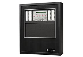
Service: Inspect detectors, call points, panels, loops, power supplies and interfaces according to the approved fire-system test plan. Keep sensing openings clean and protect devices from paint, steam and dust during maintenance. Function-test alarms, zone identification, sounders and required output relays using approved test tools and procedures. Check backup batteries and power-failure indications and record any isolated zone or disabled device. Restore all bypasses and isolations after work. Refer to the manufacturer documentation for the exact figure for test frequencies, detector limits and replacement procedures.
Spare Parts: Keep approved detector heads, bases, manual-call-point elements, loop modules, fuses, batteries, relays and selected panel components compatible with the installed system. Replacement devices must preserve addressing and type approval. Maintain approved test tools and detector-specific service accessories.
Use Cases: Automatic and manual fire detection in machinery spaces, accommodation, cargo areas and other protected shipboard spaces.
Consilium Marine 1L×32D-C unverified
Loops
1
Devices per Loop
32
Addressable
ja
IMO Compliant
ja
Common Failures & Inspection Points
  • Detector or sensing-element contamination caused by dust, grease, moisture or aging, resulting in false alarms, slow response or fault indication
  • Loop or cable fault caused by damaged wiring, loose terminals or earth leakage, resulting in missing devices or intermittent system faults
  • Addressing or configuration error caused by replacement or software changes, resulting in incorrect device identification or unavailable zones
  • Power-supply or backup-battery deterioration caused by charger faults or aged batteries, resulting in power alarms or reduced standby capability
  • Panel, relay or communication failure caused by electronics faults, resulting in missing alarms, failed outputs or loss of connection to other safety systems
Service: Inspect detectors, call points, panels, loops, power supplies and interfaces according to the approved fire-system test plan. Keep sensing openings clean and protect devices from paint, steam and dust. Function-test alarms, zone identification, sounders and required output relays using approved test tools and procedures. Check backup batteries and power-failure indications and record any isolated zone or disabled device. Restore all bypasses and isolations after work. Refer to the manufacturer documentation for the exact figure for test frequency, detector limits and replacement procedures.
Spare Parts: Keep approved detector heads, bases, call-point elements, loop modules, fuses, batteries, relays and selected panel components compatible with the installed system. Replacement devices must preserve addressing and type approval.
Use Cases: It is used for shipboard fire detection on merchant ships, passenger vessels, offshore units or other vessel types where this equipment category is fitted.
Consilium Marine 1L×64D-C unverified
Loops
1
Devices per Loop
64
Addressable
ja
IMO Compliant
ja
Common Failures & Inspection Points
  • Detector or sensing-element contamination caused by dust, grease, moisture or aging, resulting in false alarms, slow response or fault indication
  • Loop or cable fault caused by damaged wiring, loose terminals or earth leakage, resulting in missing devices or intermittent system faults
  • Addressing or configuration error caused by replacement or software changes, resulting in incorrect device identification or unavailable zones
  • Power-supply or backup-battery deterioration caused by charger faults or aged batteries, resulting in power alarms or reduced standby capability
  • Panel, relay or communication failure caused by electronics faults, resulting in missing alarms, failed outputs or loss of connection to other safety systems
Service: Inspect detectors, call points, panels, loops, power supplies and interfaces according to the approved fire-system test plan. Keep sensing openings clean and protect devices from paint, steam and dust. Function-test alarms, zone identification, sounders and required output relays using approved test tools and procedures. Check backup batteries and power-failure indications and record any isolated zone or disabled device. Restore all bypasses and isolations after work. Refer to the manufacturer documentation for the exact figure for test frequency, detector limits and replacement procedures.
Spare Parts: Keep approved detector heads, bases, call-point elements, loop modules, fuses, batteries, relays and selected panel components compatible with the installed system. Replacement devices must preserve addressing and type approval.
Use Cases: It is used for shipboard fire detection on merchant ships, passenger vessels, offshore units or other vessel types where this equipment category is fitted.
Consilium Marine 1L×126D-C unverified
Loops
1
Devices per Loop
126
Addressable
ja
IMO Compliant
ja
Common Failures & Inspection Points
  • Detector or sensing-element contamination caused by dust, grease, moisture or aging, resulting in false alarms, slow response or fault indication
  • Loop or cable fault caused by damaged wiring, loose terminals or earth leakage, resulting in missing devices or intermittent system faults
  • Addressing or configuration error caused by replacement or software changes, resulting in incorrect device identification or unavailable zones
  • Power-supply or backup-battery deterioration caused by charger faults or aged batteries, resulting in power alarms or reduced standby capability
  • Panel, relay or communication failure caused by electronics faults, resulting in missing alarms, failed outputs or loss of connection to other safety systems
Service: Inspect detectors, call points, panels, loops, power supplies and interfaces according to the approved fire-system test plan. Keep sensing openings clean and protect devices from paint, steam and dust. Function-test alarms, zone identification, sounders and required output relays using approved test tools and procedures. Check backup batteries and power-failure indications and record any isolated zone or disabled device. Restore all bypasses and isolations after work. Refer to the manufacturer documentation for the exact figure for test frequency, detector limits and replacement procedures.
Spare Parts: Keep approved detector heads, bases, call-point elements, loop modules, fuses, batteries, relays and selected panel components compatible with the installed system. Replacement devices must preserve addressing and type approval.
Use Cases: It is used for shipboard fire detection on merchant ships, passenger vessels, offshore units or other vessel types where this equipment category is fitted.
Consilium Marine 1L×127D-C unverified
Loops
1
Devices per Loop
127
Addressable
ja
IMO Compliant
ja
Common Failures & Inspection Points
  • Detector or sensing-element contamination caused by dust, grease, moisture or aging, resulting in false alarms, slow response or fault indication
  • Loop or cable fault caused by damaged wiring, loose terminals or earth leakage, resulting in missing devices or intermittent system faults
  • Addressing or configuration error caused by replacement or software changes, resulting in incorrect device identification or unavailable zones
  • Power-supply or backup-battery deterioration caused by charger faults or aged batteries, resulting in power alarms or reduced standby capability
  • Panel, relay or communication failure caused by electronics faults, resulting in missing alarms, failed outputs or loss of connection to other safety systems
Service: Inspect detectors, call points, panels, loops, power supplies and interfaces according to the approved fire-system test plan. Keep sensing openings clean and protect devices from paint, steam and dust. Function-test alarms, zone identification, sounders and required output relays using approved test tools and procedures. Check backup batteries and power-failure indications and record any isolated zone or disabled device. Restore all bypasses and isolations after work. Refer to the manufacturer documentation for the exact figure for test frequency, detector limits and replacement procedures.
Spare Parts: Keep approved detector heads, bases, call-point elements, loop modules, fuses, batteries, relays and selected panel components compatible with the installed system. Replacement devices must preserve addressing and type approval.
Use Cases: It is used for shipboard fire detection on merchant ships, passenger vessels, offshore units or other vessel types where this equipment category is fitted.
Consilium Marine 1L×252D-C unverified
Loops
1
Devices per Loop
252
Addressable
ja
IMO Compliant
ja
Common Failures & Inspection Points
  • Detector or sensing-element contamination caused by dust, grease, moisture or aging, resulting in false alarms, slow response or fault indication
  • Loop or cable fault caused by damaged wiring, loose terminals or earth leakage, resulting in missing devices or intermittent system faults
  • Addressing or configuration error caused by replacement or software changes, resulting in incorrect device identification or unavailable zones
  • Power-supply or backup-battery deterioration caused by charger faults or aged batteries, resulting in power alarms or reduced standby capability
  • Panel, relay or communication failure caused by electronics faults, resulting in missing alarms, failed outputs or loss of connection to other safety systems
Service: Inspect detectors, call points, panels, loops, power supplies and interfaces according to the approved fire-system test plan. Keep sensing openings clean and protect devices from paint, steam and dust. Function-test alarms, zone identification, sounders and required output relays using approved test tools and procedures. Check backup batteries and power-failure indications and record any isolated zone or disabled device. Restore all bypasses and isolations after work. Refer to the manufacturer documentation for the exact figure for test frequency, detector limits and replacement procedures.
Spare Parts: Keep approved detector heads, bases, call-point elements, loop modules, fuses, batteries, relays and selected panel components compatible with the installed system. Replacement devices must preserve addressing and type approval.
Use Cases: It is used for shipboard fire detection on merchant ships, passenger vessels, offshore units or other vessel types where this equipment category is fitted.
Consilium Marine 1L×254D-C unverified
Loops
1
Devices per Loop
254
Addressable
ja
IMO Compliant
ja
Common Failures & Inspection Points
  • Detector or sensing-element contamination caused by dust, grease, moisture or aging, resulting in false alarms, slow response or fault indication
  • Loop or cable fault caused by damaged wiring, loose terminals or earth leakage, resulting in missing devices or intermittent system faults
  • Addressing or configuration error caused by replacement or software changes, resulting in incorrect device identification or unavailable zones
  • Power-supply or backup-battery deterioration caused by charger faults or aged batteries, resulting in power alarms or reduced standby capability
  • Panel, relay or communication failure caused by electronics faults, resulting in missing alarms, failed outputs or loss of connection to other safety systems
Service: Inspect detectors, call points, panels, loops, power supplies and interfaces according to the approved fire-system test plan. Keep sensing openings clean and protect devices from paint, steam and dust. Function-test alarms, zone identification, sounders and required output relays using approved test tools and procedures. Check backup batteries and power-failure indications and record any isolated zone or disabled device. Restore all bypasses and isolations after work. Refer to the manufacturer documentation for the exact figure for test frequency, detector limits and replacement procedures.
Spare Parts: Keep approved detector heads, bases, call-point elements, loop modules, fuses, batteries, relays and selected panel components compatible with the installed system. Replacement devices must preserve addressing and type approval.
Use Cases: It is used for shipboard fire detection on merchant ships, passenger vessels, offshore units or other vessel types where this equipment category is fitted.
Consilium Marine 2L×32D-C unverified
Loops
2
Devices per Loop
32
Addressable
ja
IMO Compliant
ja
Common Failures & Inspection Points
  • Detector or sensing-element contamination caused by dust, grease, moisture or aging, resulting in false alarms, slow response or fault indication
  • Loop or cable fault caused by damaged wiring, loose terminals or earth leakage, resulting in missing devices or intermittent system faults
  • Addressing or configuration error caused by replacement or software changes, resulting in incorrect device identification or unavailable zones
  • Power-supply or backup-battery deterioration caused by charger faults or aged batteries, resulting in power alarms or reduced standby capability
  • Panel, relay or communication failure caused by electronics faults, resulting in missing alarms, failed outputs or loss of connection to other safety systems
Service: Inspect detectors, call points, panels, loops, power supplies and interfaces according to the approved fire-system test plan. Keep sensing openings clean and protect devices from paint, steam and dust. Function-test alarms, zone identification, sounders and required output relays using approved test tools and procedures. Check backup batteries and power-failure indications and record any isolated zone or disabled device. Restore all bypasses and isolations after work. Refer to the manufacturer documentation for the exact figure for test frequency, detector limits and replacement procedures.
Spare Parts: Keep approved detector heads, bases, call-point elements, loop modules, fuses, batteries, relays and selected panel components compatible with the installed system. Replacement devices must preserve addressing and type approval.
Use Cases: It is used for shipboard fire detection on merchant ships, passenger vessels, offshore units or other vessel types where this equipment category is fitted.
Consilium Marine 2L×64D-C unverified
Loops
2
Devices per Loop
64
Addressable
ja
IMO Compliant
ja
Common Failures & Inspection Points
  • Detector or sensing-element contamination caused by dust, grease, moisture or aging, resulting in false alarms, slow response or fault indication
  • Loop or cable fault caused by damaged wiring, loose terminals or earth leakage, resulting in missing devices or intermittent system faults
  • Addressing or configuration error caused by replacement or software changes, resulting in incorrect device identification or unavailable zones
  • Power-supply or backup-battery deterioration caused by charger faults or aged batteries, resulting in power alarms or reduced standby capability
  • Panel, relay or communication failure caused by electronics faults, resulting in missing alarms, failed outputs or loss of connection to other safety systems
Service: Inspect detectors, call points, panels, loops, power supplies and interfaces according to the approved fire-system test plan. Keep sensing openings clean and protect devices from paint, steam and dust. Function-test alarms, zone identification, sounders and required output relays using approved test tools and procedures. Check backup batteries and power-failure indications and record any isolated zone or disabled device. Restore all bypasses and isolations after work. Refer to the manufacturer documentation for the exact figure for test frequency, detector limits and replacement procedures.
Spare Parts: Keep approved detector heads, bases, call-point elements, loop modules, fuses, batteries, relays and selected panel components compatible with the installed system. Replacement devices must preserve addressing and type approval.
Use Cases: It is used for shipboard fire detection on merchant ships, passenger vessels, offshore units or other vessel types where this equipment category is fitted.
Consilium Marine 2L×126D-C unverified
Loops
2
Devices per Loop
126
Addressable
ja
IMO Compliant
ja
Common Failures & Inspection Points
  • Detector or sensing-element contamination caused by dust, grease, moisture or aging, resulting in false alarms, slow response or fault indication
  • Loop or cable fault caused by damaged wiring, loose terminals or earth leakage, resulting in missing devices or intermittent system faults
  • Addressing or configuration error caused by replacement or software changes, resulting in incorrect device identification or unavailable zones
  • Power-supply or backup-battery deterioration caused by charger faults or aged batteries, resulting in power alarms or reduced standby capability
  • Panel, relay or communication failure caused by electronics faults, resulting in missing alarms, failed outputs or loss of connection to other safety systems
Service: Inspect detectors, call points, panels, loops, power supplies and interfaces according to the approved fire-system test plan. Keep sensing openings clean and protect devices from paint, steam and dust. Function-test alarms, zone identification, sounders and required output relays using approved test tools and procedures. Check backup batteries and power-failure indications and record any isolated zone or disabled device. Restore all bypasses and isolations after work. Refer to the manufacturer documentation for the exact figure for test frequency, detector limits and replacement procedures.
Spare Parts: Keep approved detector heads, bases, call-point elements, loop modules, fuses, batteries, relays and selected panel components compatible with the installed system. Replacement devices must preserve addressing and type approval.
Use Cases: It is used for shipboard fire detection on merchant ships, passenger vessels, offshore units or other vessel types where this equipment category is fitted.
Consilium Marine 2L×127D-C unverified
Loops
2
Devices per Loop
127
Addressable
ja
IMO Compliant
ja
Common Failures & Inspection Points
  • Detector or sensing-element contamination caused by dust, grease, moisture or aging, resulting in false alarms, slow response or fault indication
  • Loop or cable fault caused by damaged wiring, loose terminals or earth leakage, resulting in missing devices or intermittent system faults
  • Addressing or configuration error caused by replacement or software changes, resulting in incorrect device identification or unavailable zones
  • Power-supply or backup-battery deterioration caused by charger faults or aged batteries, resulting in power alarms or reduced standby capability
  • Panel, relay or communication failure caused by electronics faults, resulting in missing alarms, failed outputs or loss of connection to other safety systems
Service: Inspect detectors, call points, panels, loops, power supplies and interfaces according to the approved fire-system test plan. Keep sensing openings clean and protect devices from paint, steam and dust. Function-test alarms, zone identification, sounders and required output relays using approved test tools and procedures. Check backup batteries and power-failure indications and record any isolated zone or disabled device. Restore all bypasses and isolations after work. Refer to the manufacturer documentation for the exact figure for test frequency, detector limits and replacement procedures.
Spare Parts: Keep approved detector heads, bases, call-point elements, loop modules, fuses, batteries, relays and selected panel components compatible with the installed system. Replacement devices must preserve addressing and type approval.
Use Cases: It is used for shipboard fire detection on merchant ships, passenger vessels, offshore units or other vessel types where this equipment category is fitted.
Consilium Marine 2L×252D-C unverified
Loops
2
Devices per Loop
252
Addressable
ja
IMO Compliant
ja
Common Failures & Inspection Points
  • Detector or sensing-element contamination caused by dust, grease, moisture or aging, resulting in false alarms, slow response or fault indication
  • Loop or cable fault caused by damaged wiring, loose terminals or earth leakage, resulting in missing devices or intermittent system faults
  • Addressing or configuration error caused by replacement or software changes, resulting in incorrect device identification or unavailable zones
  • Power-supply or backup-battery deterioration caused by charger faults or aged batteries, resulting in power alarms or reduced standby capability
  • Panel, relay or communication failure caused by electronics faults, resulting in missing alarms, failed outputs or loss of connection to other safety systems
Service: Inspect detectors, call points, panels, loops, power supplies and interfaces according to the approved fire-system test plan. Keep sensing openings clean and protect devices from paint, steam and dust. Function-test alarms, zone identification, sounders and required output relays using approved test tools and procedures. Check backup batteries and power-failure indications and record any isolated zone or disabled device. Restore all bypasses and isolations after work. Refer to the manufacturer documentation for the exact figure for test frequency, detector limits and replacement procedures.
Spare Parts: Keep approved detector heads, bases, call-point elements, loop modules, fuses, batteries, relays and selected panel components compatible with the installed system. Replacement devices must preserve addressing and type approval.
Use Cases: It is used for shipboard fire detection on merchant ships, passenger vessels, offshore units or other vessel types where this equipment category is fitted.
Consilium Marine 2L×254D-C unverified
Loops
2
Devices per Loop
254
Addressable
ja
IMO Compliant
ja
Common Failures & Inspection Points
  • Detector or sensing-element contamination caused by dust, grease, moisture or aging, resulting in false alarms, slow response or fault indication
  • Loop or cable fault caused by damaged wiring, loose terminals or earth leakage, resulting in missing devices or intermittent system faults
  • Addressing or configuration error caused by replacement or software changes, resulting in incorrect device identification or unavailable zones
  • Power-supply or backup-battery deterioration caused by charger faults or aged batteries, resulting in power alarms or reduced standby capability
  • Panel, relay or communication failure caused by electronics faults, resulting in missing alarms, failed outputs or loss of connection to other safety systems
Service: Inspect detectors, call points, panels, loops, power supplies and interfaces according to the approved fire-system test plan. Keep sensing openings clean and protect devices from paint, steam and dust. Function-test alarms, zone identification, sounders and required output relays using approved test tools and procedures. Check backup batteries and power-failure indications and record any isolated zone or disabled device. Restore all bypasses and isolations after work. Refer to the manufacturer documentation for the exact figure for test frequency, detector limits and replacement procedures.
Spare Parts: Keep approved detector heads, bases, call-point elements, loop modules, fuses, batteries, relays and selected panel components compatible with the installed system. Replacement devices must preserve addressing and type approval.
Use Cases: It is used for shipboard fire detection on merchant ships, passenger vessels, offshore units or other vessel types where this equipment category is fitted.
Consilium Marine 4L×32D-C unverified
Loops
4
Devices per Loop
32
Addressable
ja
IMO Compliant
ja
Common Failures & Inspection Points
  • Detector or sensing-element contamination caused by dust, grease, moisture or aging, resulting in false alarms, slow response or fault indication
  • Loop or cable fault caused by damaged wiring, loose terminals or earth leakage, resulting in missing devices or intermittent system faults
  • Addressing or configuration error caused by replacement or software changes, resulting in incorrect device identification or unavailable zones
  • Power-supply or backup-battery deterioration caused by charger faults or aged batteries, resulting in power alarms or reduced standby capability
  • Panel, relay or communication failure caused by electronics faults, resulting in missing alarms, failed outputs or loss of connection to other safety systems
Service: Inspect detectors, call points, panels, loops, power supplies and interfaces according to the approved fire-system test plan. Keep sensing openings clean and protect devices from paint, steam and dust. Function-test alarms, zone identification, sounders and required output relays using approved test tools and procedures. Check backup batteries and power-failure indications and record any isolated zone or disabled device. Restore all bypasses and isolations after work. Refer to the manufacturer documentation for the exact figure for test frequency, detector limits and replacement procedures.
Spare Parts: Keep approved detector heads, bases, call-point elements, loop modules, fuses, batteries, relays and selected panel components compatible with the installed system. Replacement devices must preserve addressing and type approval.
Use Cases: It is used for shipboard fire detection on merchant ships, passenger vessels, offshore units or other vessel types where this equipment category is fitted.
Consilium Marine 4L×64D-C unverified
Loops
4
Devices per Loop
64
Addressable
ja
IMO Compliant
ja
Common Failures & Inspection Points
  • Detector or sensing-element contamination caused by dust, grease, moisture or aging, resulting in false alarms, slow response or fault indication
  • Loop or cable fault caused by damaged wiring, loose terminals or earth leakage, resulting in missing devices or intermittent system faults
  • Addressing or configuration error caused by replacement or software changes, resulting in incorrect device identification or unavailable zones
  • Power-supply or backup-battery deterioration caused by charger faults or aged batteries, resulting in power alarms or reduced standby capability
  • Panel, relay or communication failure caused by electronics faults, resulting in missing alarms, failed outputs or loss of connection to other safety systems
Service: Inspect detectors, call points, panels, loops, power supplies and interfaces according to the approved fire-system test plan. Keep sensing openings clean and protect devices from paint, steam and dust. Function-test alarms, zone identification, sounders and required output relays using approved test tools and procedures. Check backup batteries and power-failure indications and record any isolated zone or disabled device. Restore all bypasses and isolations after work. Refer to the manufacturer documentation for the exact figure for test frequency, detector limits and replacement procedures.
Spare Parts: Keep approved detector heads, bases, call-point elements, loop modules, fuses, batteries, relays and selected panel components compatible with the installed system. Replacement devices must preserve addressing and type approval.
Use Cases: It is used for shipboard fire detection on merchant ships, passenger vessels, offshore units or other vessel types where this equipment category is fitted.
Consilium Marine 4L×126D-C unverified
Loops
4
Devices per Loop
126
Addressable
ja
IMO Compliant
ja
Common Failures & Inspection Points
  • Detector or sensing-element contamination caused by dust, grease, moisture or aging, resulting in false alarms, slow response or fault indication
  • Loop or cable fault caused by damaged wiring, loose terminals or earth leakage, resulting in missing devices or intermittent system faults
  • Addressing or configuration error caused by replacement or software changes, resulting in incorrect device identification or unavailable zones
  • Power-supply or backup-battery deterioration caused by charger faults or aged batteries, resulting in power alarms or reduced standby capability
  • Panel, relay or communication failure caused by electronics faults, resulting in missing alarms, failed outputs or loss of connection to other safety systems
Service: Inspect detectors, call points, panels, loops, power supplies and interfaces according to the approved fire-system test plan. Keep sensing openings clean and protect devices from paint, steam and dust. Function-test alarms, zone identification, sounders and required output relays using approved test tools and procedures. Check backup batteries and power-failure indications and record any isolated zone or disabled device. Restore all bypasses and isolations after work. Refer to the manufacturer documentation for the exact figure for test frequency, detector limits and replacement procedures.
Spare Parts: Keep approved detector heads, bases, call-point elements, loop modules, fuses, batteries, relays and selected panel components compatible with the installed system. Replacement devices must preserve addressing and type approval.
Use Cases: It is used for shipboard fire detection on merchant ships, passenger vessels, offshore units or other vessel types where this equipment category is fitted.
Consilium Marine 4L×127D-C unverified
Loops
4
Devices per Loop
127
Addressable
ja
IMO Compliant
ja
Common Failures & Inspection Points
  • Detector or sensing-element contamination caused by dust, grease, moisture or aging, resulting in false alarms, slow response or fault indication
  • Loop or cable fault caused by damaged wiring, loose terminals or earth leakage, resulting in missing devices or intermittent system faults
  • Addressing or configuration error caused by replacement or software changes, resulting in incorrect device identification or unavailable zones
  • Power-supply or backup-battery deterioration caused by charger faults or aged batteries, resulting in power alarms or reduced standby capability
  • Panel, relay or communication failure caused by electronics faults, resulting in missing alarms, failed outputs or loss of connection to other safety systems
Service: Inspect detectors, call points, panels, loops, power supplies and interfaces according to the approved fire-system test plan. Keep sensing openings clean and protect devices from paint, steam and dust. Function-test alarms, zone identification, sounders and required output relays using approved test tools and procedures. Check backup batteries and power-failure indications and record any isolated zone or disabled device. Restore all bypasses and isolations after work. Refer to the manufacturer documentation for the exact figure for test frequency, detector limits and replacement procedures.
Spare Parts: Keep approved detector heads, bases, call-point elements, loop modules, fuses, batteries, relays and selected panel components compatible with the installed system. Replacement devices must preserve addressing and type approval.
Use Cases: It is used for shipboard fire detection on merchant ships, passenger vessels, offshore units or other vessel types where this equipment category is fitted.
Consilium Marine 4L×252D-C unverified
Loops
4
Devices per Loop
252
Addressable
ja
IMO Compliant
ja
Common Failures & Inspection Points
  • Detector or sensing-element contamination caused by dust, grease, moisture or aging, resulting in false alarms, slow response or fault indication
  • Loop or cable fault caused by damaged wiring, loose terminals or earth leakage, resulting in missing devices or intermittent system faults
  • Addressing or configuration error caused by replacement or software changes, resulting in incorrect device identification or unavailable zones
  • Power-supply or backup-battery deterioration caused by charger faults or aged batteries, resulting in power alarms or reduced standby capability
  • Panel, relay or communication failure caused by electronics faults, resulting in missing alarms, failed outputs or loss of connection to other safety systems
Service: Inspect detectors, call points, panels, loops, power supplies and interfaces according to the approved fire-system test plan. Keep sensing openings clean and protect devices from paint, steam and dust. Function-test alarms, zone identification, sounders and required output relays using approved test tools and procedures. Check backup batteries and power-failure indications and record any isolated zone or disabled device. Restore all bypasses and isolations after work. Refer to the manufacturer documentation for the exact figure for test frequency, detector limits and replacement procedures.
Spare Parts: Keep approved detector heads, bases, call-point elements, loop modules, fuses, batteries, relays and selected panel components compatible with the installed system. Replacement devices must preserve addressing and type approval.
Use Cases: It is used for shipboard fire detection on merchant ships, passenger vessels, offshore units or other vessel types where this equipment category is fitted.
Consilium Marine 4L×254D-C unverified
Loops
4
Devices per Loop
254
Addressable
ja
IMO Compliant
ja
Common Failures & Inspection Points
  • Detector or sensing-element contamination caused by dust, grease, moisture or aging, resulting in false alarms, slow response or fault indication
  • Loop or cable fault caused by damaged wiring, loose terminals or earth leakage, resulting in missing devices or intermittent system faults
  • Addressing or configuration error caused by replacement or software changes, resulting in incorrect device identification or unavailable zones
  • Power-supply or backup-battery deterioration caused by charger faults or aged batteries, resulting in power alarms or reduced standby capability
  • Panel, relay or communication failure caused by electronics faults, resulting in missing alarms, failed outputs or loss of connection to other safety systems
Service: Inspect detectors, call points, panels, loops, power supplies and interfaces according to the approved fire-system test plan. Keep sensing openings clean and protect devices from paint, steam and dust. Function-test alarms, zone identification, sounders and required output relays using approved test tools and procedures. Check backup batteries and power-failure indications and record any isolated zone or disabled device. Restore all bypasses and isolations after work. Refer to the manufacturer documentation for the exact figure for test frequency, detector limits and replacement procedures.
Spare Parts: Keep approved detector heads, bases, call-point elements, loop modules, fuses, batteries, relays and selected panel components compatible with the installed system. Replacement devices must preserve addressing and type approval.
Use Cases: It is used for shipboard fire detection on merchant ships, passenger vessels, offshore units or other vessel types where this equipment category is fitted.
Consilium Marine 6L×32D-C unverified
Loops
6
Devices per Loop
32
Addressable
ja
IMO Compliant
ja
Common Failures & Inspection Points
  • Detector or sensing-element contamination caused by dust, grease, moisture or aging, resulting in false alarms, slow response or fault indication
  • Loop or cable fault caused by damaged wiring, loose terminals or earth leakage, resulting in missing devices or intermittent system faults
  • Addressing or configuration error caused by replacement or software changes, resulting in incorrect device identification or unavailable zones
  • Power-supply or backup-battery deterioration caused by charger faults or aged batteries, resulting in power alarms or reduced standby capability
  • Panel, relay or communication failure caused by electronics faults, resulting in missing alarms, failed outputs or loss of connection to other safety systems
Service: Inspect detectors, call points, panels, loops, power supplies and interfaces according to the approved fire-system test plan. Keep sensing openings clean and protect devices from paint, steam and dust. Function-test alarms, zone identification, sounders and required output relays using approved test tools and procedures. Check backup batteries and power-failure indications and record any isolated zone or disabled device. Restore all bypasses and isolations after work. Refer to the manufacturer documentation for the exact figure for test frequency, detector limits and replacement procedures.
Spare Parts: Keep approved detector heads, bases, call-point elements, loop modules, fuses, batteries, relays and selected panel components compatible with the installed system. Replacement devices must preserve addressing and type approval.
Use Cases: It is used for shipboard fire detection on merchant ships, passenger vessels, offshore units or other vessel types where this equipment category is fitted.
Consilium Marine 6L×64D-C unverified
Loops
6
Devices per Loop
64
Addressable
ja
IMO Compliant
ja
Common Failures & Inspection Points
  • Detector or sensing-element contamination caused by dust, grease, moisture or aging, resulting in false alarms, slow response or fault indication
  • Loop or cable fault caused by damaged wiring, loose terminals or earth leakage, resulting in missing devices or intermittent system faults
  • Addressing or configuration error caused by replacement or software changes, resulting in incorrect device identification or unavailable zones
  • Power-supply or backup-battery deterioration caused by charger faults or aged batteries, resulting in power alarms or reduced standby capability
  • Panel, relay or communication failure caused by electronics faults, resulting in missing alarms, failed outputs or loss of connection to other safety systems
Service: Inspect detectors, call points, panels, loops, power supplies and interfaces according to the approved fire-system test plan. Keep sensing openings clean and protect devices from paint, steam and dust. Function-test alarms, zone identification, sounders and required output relays using approved test tools and procedures. Check backup batteries and power-failure indications and record any isolated zone or disabled device. Restore all bypasses and isolations after work. Refer to the manufacturer documentation for the exact figure for test frequency, detector limits and replacement procedures.
Spare Parts: Keep approved detector heads, bases, call-point elements, loop modules, fuses, batteries, relays and selected panel components compatible with the installed system. Replacement devices must preserve addressing and type approval.
Use Cases: It is used for shipboard fire detection on merchant ships, passenger vessels, offshore units or other vessel types where this equipment category is fitted.
Consilium Marine 6L×126D-C unverified
Loops
6
Devices per Loop
126
Addressable
ja
IMO Compliant
ja
Common Failures & Inspection Points
  • Detector or sensing-element contamination caused by dust, grease, moisture or aging, resulting in false alarms, slow response or fault indication
  • Loop or cable fault caused by damaged wiring, loose terminals or earth leakage, resulting in missing devices or intermittent system faults
  • Addressing or configuration error caused by replacement or software changes, resulting in incorrect device identification or unavailable zones
  • Power-supply or backup-battery deterioration caused by charger faults or aged batteries, resulting in power alarms or reduced standby capability
  • Panel, relay or communication failure caused by electronics faults, resulting in missing alarms, failed outputs or loss of connection to other safety systems
Service: Inspect detectors, call points, panels, loops, power supplies and interfaces according to the approved fire-system test plan. Keep sensing openings clean and protect devices from paint, steam and dust. Function-test alarms, zone identification, sounders and required output relays using approved test tools and procedures. Check backup batteries and power-failure indications and record any isolated zone or disabled device. Restore all bypasses and isolations after work. Refer to the manufacturer documentation for the exact figure for test frequency, detector limits and replacement procedures.
Spare Parts: Keep approved detector heads, bases, call-point elements, loop modules, fuses, batteries, relays and selected panel components compatible with the installed system. Replacement devices must preserve addressing and type approval.
Use Cases: It is used for shipboard fire detection on merchant ships, passenger vessels, offshore units or other vessel types where this equipment category is fitted.
Consilium Marine 6L×127D-C unverified
Loops
6
Devices per Loop
127
Addressable
ja
IMO Compliant
ja
Common Failures & Inspection Points
  • Detector or sensing-element contamination caused by dust, grease, moisture or aging, resulting in false alarms, slow response or fault indication
  • Loop or cable fault caused by damaged wiring, loose terminals or earth leakage, resulting in missing devices or intermittent system faults
  • Addressing or configuration error caused by replacement or software changes, resulting in incorrect device identification or unavailable zones
  • Power-supply or backup-battery deterioration caused by charger faults or aged batteries, resulting in power alarms or reduced standby capability
  • Panel, relay or communication failure caused by electronics faults, resulting in missing alarms, failed outputs or loss of connection to other safety systems
Service: Inspect detectors, call points, panels, loops, power supplies and interfaces according to the approved fire-system test plan. Keep sensing openings clean and protect devices from paint, steam and dust. Function-test alarms, zone identification, sounders and required output relays using approved test tools and procedures. Check backup batteries and power-failure indications and record any isolated zone or disabled device. Restore all bypasses and isolations after work. Refer to the manufacturer documentation for the exact figure for test frequency, detector limits and replacement procedures.
Spare Parts: Keep approved detector heads, bases, call-point elements, loop modules, fuses, batteries, relays and selected panel components compatible with the installed system. Replacement devices must preserve addressing and type approval.
Use Cases: It is used for shipboard fire detection on merchant ships, passenger vessels, offshore units or other vessel types where this equipment category is fitted.
Consilium Marine 6L×252D-C unverified
Loops
6
Devices per Loop
252
Addressable
ja
IMO Compliant
ja
Common Failures & Inspection Points
  • Detector or sensing-element contamination caused by dust, grease, moisture or aging, resulting in false alarms, slow response or fault indication
  • Loop or cable fault caused by damaged wiring, loose terminals or earth leakage, resulting in missing devices or intermittent system faults
  • Addressing or configuration error caused by replacement or software changes, resulting in incorrect device identification or unavailable zones
  • Power-supply or backup-battery deterioration caused by charger faults or aged batteries, resulting in power alarms or reduced standby capability
  • Panel, relay or communication failure caused by electronics faults, resulting in missing alarms, failed outputs or loss of connection to other safety systems
Service: Inspect detectors, call points, panels, loops, power supplies and interfaces according to the approved fire-system test plan. Keep sensing openings clean and protect devices from paint, steam and dust. Function-test alarms, zone identification, sounders and required output relays using approved test tools and procedures. Check backup batteries and power-failure indications and record any isolated zone or disabled device. Restore all bypasses and isolations after work. Refer to the manufacturer documentation for the exact figure for test frequency, detector limits and replacement procedures.
Spare Parts: Keep approved detector heads, bases, call-point elements, loop modules, fuses, batteries, relays and selected panel components compatible with the installed system. Replacement devices must preserve addressing and type approval.
Use Cases: It is used for shipboard fire detection on merchant ships, passenger vessels, offshore units or other vessel types where this equipment category is fitted.
Consilium Marine 6L×254D-C unverified
Loops
6
Devices per Loop
254
Addressable
ja
IMO Compliant
ja
Common Failures & Inspection Points
  • Detector or sensing-element contamination caused by dust, grease, moisture or aging, resulting in false alarms, slow response or fault indication
  • Loop or cable fault caused by damaged wiring, loose terminals or earth leakage, resulting in missing devices or intermittent system faults
  • Addressing or configuration error caused by replacement or software changes, resulting in incorrect device identification or unavailable zones
  • Power-supply or backup-battery deterioration caused by charger faults or aged batteries, resulting in power alarms or reduced standby capability
  • Panel, relay or communication failure caused by electronics faults, resulting in missing alarms, failed outputs or loss of connection to other safety systems
Service: Inspect detectors, call points, panels, loops, power supplies and interfaces according to the approved fire-system test plan. Keep sensing openings clean and protect devices from paint, steam and dust. Function-test alarms, zone identification, sounders and required output relays using approved test tools and procedures. Check backup batteries and power-failure indications and record any isolated zone or disabled device. Restore all bypasses and isolations after work. Refer to the manufacturer documentation for the exact figure for test frequency, detector limits and replacement procedures.
Spare Parts: Keep approved detector heads, bases, call-point elements, loop modules, fuses, batteries, relays and selected panel components compatible with the installed system. Replacement devices must preserve addressing and type approval.
Use Cases: It is used for shipboard fire detection on merchant ships, passenger vessels, offshore units or other vessel types where this equipment category is fitted.
Consilium Marine 8L×32D-C unverified
Loops
8
Devices per Loop
32
Addressable
ja
IMO Compliant
ja
Common Failures & Inspection Points
  • Detector or sensing-element contamination caused by dust, grease, moisture or aging, resulting in false alarms, slow response or fault indication
  • Loop or cable fault caused by damaged wiring, loose terminals or earth leakage, resulting in missing devices or intermittent system faults
  • Addressing or configuration error caused by replacement or software changes, resulting in incorrect device identification or unavailable zones
  • Power-supply or backup-battery deterioration caused by charger faults or aged batteries, resulting in power alarms or reduced standby capability
  • Panel, relay or communication failure caused by electronics faults, resulting in missing alarms, failed outputs or loss of connection to other safety systems
Service: Inspect detectors, call points, panels, loops, power supplies and interfaces according to the approved fire-system test plan. Keep sensing openings clean and protect devices from paint, steam and dust. Function-test alarms, zone identification, sounders and required output relays using approved test tools and procedures. Check backup batteries and power-failure indications and record any isolated zone or disabled device. Restore all bypasses and isolations after work. Refer to the manufacturer documentation for the exact figure for test frequency, detector limits and replacement procedures.
Spare Parts: Keep approved detector heads, bases, call-point elements, loop modules, fuses, batteries, relays and selected panel components compatible with the installed system. Replacement devices must preserve addressing and type approval.
Use Cases: It is used for shipboard fire detection on merchant ships, passenger vessels, offshore units or other vessel types where this equipment category is fitted.
Consilium Marine 8L×64D-C unverified
Loops
8
Devices per Loop
64
Addressable
ja
IMO Compliant
ja
Common Failures & Inspection Points
  • Detector or sensing-element contamination caused by dust, grease, moisture or aging, resulting in false alarms, slow response or fault indication
  • Loop or cable fault caused by damaged wiring, loose terminals or earth leakage, resulting in missing devices or intermittent system faults
  • Addressing or configuration error caused by replacement or software changes, resulting in incorrect device identification or unavailable zones
  • Power-supply or backup-battery deterioration caused by charger faults or aged batteries, resulting in power alarms or reduced standby capability
  • Panel, relay or communication failure caused by electronics faults, resulting in missing alarms, failed outputs or loss of connection to other safety systems
Service: Inspect detectors, call points, panels, loops, power supplies and interfaces according to the approved fire-system test plan. Keep sensing openings clean and protect devices from paint, steam and dust. Function-test alarms, zone identification, sounders and required output relays using approved test tools and procedures. Check backup batteries and power-failure indications and record any isolated zone or disabled device. Restore all bypasses and isolations after work. Refer to the manufacturer documentation for the exact figure for test frequency, detector limits and replacement procedures.
Spare Parts: Keep approved detector heads, bases, call-point elements, loop modules, fuses, batteries, relays and selected panel components compatible with the installed system. Replacement devices must preserve addressing and type approval.
Use Cases: It is used for shipboard fire detection on merchant ships, passenger vessels, offshore units or other vessel types where this equipment category is fitted.
Consilium Marine 8L×126D-C unverified
Loops
8
Devices per Loop
126
Addressable
ja
IMO Compliant
ja
Common Failures & Inspection Points
  • Detector or sensing-element contamination caused by dust, grease, moisture or aging, resulting in false alarms, slow response or fault indication
  • Loop or cable fault caused by damaged wiring, loose terminals or earth leakage, resulting in missing devices or intermittent system faults
  • Addressing or configuration error caused by replacement or software changes, resulting in incorrect device identification or unavailable zones
  • Power-supply or backup-battery deterioration caused by charger faults or aged batteries, resulting in power alarms or reduced standby capability
  • Panel, relay or communication failure caused by electronics faults, resulting in missing alarms, failed outputs or loss of connection to other safety systems
Service: Inspect detectors, call points, panels, loops, power supplies and interfaces according to the approved fire-system test plan. Keep sensing openings clean and protect devices from paint, steam and dust. Function-test alarms, zone identification, sounders and required output relays using approved test tools and procedures. Check backup batteries and power-failure indications and record any isolated zone or disabled device. Restore all bypasses and isolations after work. Refer to the manufacturer documentation for the exact figure for test frequency, detector limits and replacement procedures.
Spare Parts: Keep approved detector heads, bases, call-point elements, loop modules, fuses, batteries, relays and selected panel components compatible with the installed system. Replacement devices must preserve addressing and type approval.
Use Cases: It is used for shipboard fire detection on merchant ships, passenger vessels, offshore units or other vessel types where this equipment category is fitted.
Consilium Marine 8L×127D-C unverified
Loops
8
Devices per Loop
127
Addressable
ja
IMO Compliant
ja
Common Failures & Inspection Points
  • Detector or sensing-element contamination caused by dust, grease, moisture or aging, resulting in false alarms, slow response or fault indication
  • Loop or cable fault caused by damaged wiring, loose terminals or earth leakage, resulting in missing devices or intermittent system faults
  • Addressing or configuration error caused by replacement or software changes, resulting in incorrect device identification or unavailable zones
  • Power-supply or backup-battery deterioration caused by charger faults or aged batteries, resulting in power alarms or reduced standby capability
  • Panel, relay or communication failure caused by electronics faults, resulting in missing alarms, failed outputs or loss of connection to other safety systems
Service: Inspect detectors, call points, panels, loops, power supplies and interfaces according to the approved fire-system test plan. Keep sensing openings clean and protect devices from paint, steam and dust. Function-test alarms, zone identification, sounders and required output relays using approved test tools and procedures. Check backup batteries and power-failure indications and record any isolated zone or disabled device. Restore all bypasses and isolations after work. Refer to the manufacturer documentation for the exact figure for test frequency, detector limits and replacement procedures.
Spare Parts: Keep approved detector heads, bases, call-point elements, loop modules, fuses, batteries, relays and selected panel components compatible with the installed system. Replacement devices must preserve addressing and type approval.
Use Cases: It is used for shipboard fire detection on merchant ships, passenger vessels, offshore units or other vessel types where this equipment category is fitted.
Consilium Marine 8L×252D-C unverified
Loops
8
Devices per Loop
252
Addressable
ja
IMO Compliant
ja
Common Failures & Inspection Points
  • Detector or sensing-element contamination caused by dust, grease, moisture or aging, resulting in false alarms, slow response or fault indication
  • Loop or cable fault caused by damaged wiring, loose terminals or earth leakage, resulting in missing devices or intermittent system faults
  • Addressing or configuration error caused by replacement or software changes, resulting in incorrect device identification or unavailable zones
  • Power-supply or backup-battery deterioration caused by charger faults or aged batteries, resulting in power alarms or reduced standby capability
  • Panel, relay or communication failure caused by electronics faults, resulting in missing alarms, failed outputs or loss of connection to other safety systems
Service: Inspect detectors, call points, panels, loops, power supplies and interfaces according to the approved fire-system test plan. Keep sensing openings clean and protect devices from paint, steam and dust. Function-test alarms, zone identification, sounders and required output relays using approved test tools and procedures. Check backup batteries and power-failure indications and record any isolated zone or disabled device. Restore all bypasses and isolations after work. Refer to the manufacturer documentation for the exact figure for test frequency, detector limits and replacement procedures.
Spare Parts: Keep approved detector heads, bases, call-point elements, loop modules, fuses, batteries, relays and selected panel components compatible with the installed system. Replacement devices must preserve addressing and type approval.
Use Cases: It is used for shipboard fire detection on merchant ships, passenger vessels, offshore units or other vessel types where this equipment category is fitted.
Consilium Marine 8L×254D-C unverified
Loops
8
Devices per Loop
254
Addressable
ja
IMO Compliant
ja
Common Failures & Inspection Points
  • Detector or sensing-element contamination caused by dust, grease, moisture or aging, resulting in false alarms, slow response or fault indication
  • Loop or cable fault caused by damaged wiring, loose terminals or earth leakage, resulting in missing devices or intermittent system faults
  • Addressing or configuration error caused by replacement or software changes, resulting in incorrect device identification or unavailable zones
  • Power-supply or backup-battery deterioration caused by charger faults or aged batteries, resulting in power alarms or reduced standby capability
  • Panel, relay or communication failure caused by electronics faults, resulting in missing alarms, failed outputs or loss of connection to other safety systems
Service: Inspect detectors, call points, panels, loops, power supplies and interfaces according to the approved fire-system test plan. Keep sensing openings clean and protect devices from paint, steam and dust. Function-test alarms, zone identification, sounders and required output relays using approved test tools and procedures. Check backup batteries and power-failure indications and record any isolated zone or disabled device. Restore all bypasses and isolations after work. Refer to the manufacturer documentation for the exact figure for test frequency, detector limits and replacement procedures.
Spare Parts: Keep approved detector heads, bases, call-point elements, loop modules, fuses, batteries, relays and selected panel components compatible with the installed system. Replacement devices must preserve addressing and type approval.
Use Cases: It is used for shipboard fire detection on merchant ships, passenger vessels, offshore units or other vessel types where this equipment category is fitted.
Consilium Marine 12L×32D-C unverified
Loops
12
Devices per Loop
32
Addressable
ja
IMO Compliant
ja
Common Failures & Inspection Points
  • Detector or sensing-element contamination caused by dust, grease, moisture or aging, resulting in false alarms, slow response or fault indication
  • Loop or cable fault caused by damaged wiring, loose terminals or earth leakage, resulting in missing devices or intermittent system faults
  • Addressing or configuration error caused by replacement or software changes, resulting in incorrect device identification or unavailable zones
  • Power-supply or backup-battery deterioration caused by charger faults or aged batteries, resulting in power alarms or reduced standby capability
  • Panel, relay or communication failure caused by electronics faults, resulting in missing alarms, failed outputs or loss of connection to other safety systems
Service: Inspect detectors, call points, panels, loops, power supplies and interfaces according to the approved fire-system test plan. Keep sensing openings clean and protect devices from paint, steam and dust. Function-test alarms, zone identification, sounders and required output relays using approved test tools and procedures. Check backup batteries and power-failure indications and record any isolated zone or disabled device. Restore all bypasses and isolations after work. Refer to the manufacturer documentation for the exact figure for test frequency, detector limits and replacement procedures.
Spare Parts: Keep approved detector heads, bases, call-point elements, loop modules, fuses, batteries, relays and selected panel components compatible with the installed system. Replacement devices must preserve addressing and type approval.
Use Cases: It is used for shipboard fire detection on merchant ships, passenger vessels, offshore units or other vessel types where this equipment category is fitted.
Consilium Marine 12L×64D-C unverified
Loops
12
Devices per Loop
64
Addressable
ja
IMO Compliant
ja
Common Failures & Inspection Points
  • Detector or sensing-element contamination caused by dust, grease, moisture or aging, resulting in false alarms, slow response or fault indication
  • Loop or cable fault caused by damaged wiring, loose terminals or earth leakage, resulting in missing devices or intermittent system faults
  • Addressing or configuration error caused by replacement or software changes, resulting in incorrect device identification or unavailable zones
  • Power-supply or backup-battery deterioration caused by charger faults or aged batteries, resulting in power alarms or reduced standby capability
  • Panel, relay or communication failure caused by electronics faults, resulting in missing alarms, failed outputs or loss of connection to other safety systems
Service: Inspect detectors, call points, panels, loops, power supplies and interfaces according to the approved fire-system test plan. Keep sensing openings clean and protect devices from paint, steam and dust. Function-test alarms, zone identification, sounders and required output relays using approved test tools and procedures. Check backup batteries and power-failure indications and record any isolated zone or disabled device. Restore all bypasses and isolations after work. Refer to the manufacturer documentation for the exact figure for test frequency, detector limits and replacement procedures.
Spare Parts: Keep approved detector heads, bases, call-point elements, loop modules, fuses, batteries, relays and selected panel components compatible with the installed system. Replacement devices must preserve addressing and type approval.
Use Cases: It is used for shipboard fire detection on merchant ships, passenger vessels, offshore units or other vessel types where this equipment category is fitted.
Consilium Marine 12L×126D-C unverified
Loops
12
Devices per Loop
126
Addressable
ja
IMO Compliant
ja
Common Failures & Inspection Points
  • Detector or sensing-element contamination caused by dust, grease, moisture or aging, resulting in false alarms, slow response or fault indication
  • Loop or cable fault caused by damaged wiring, loose terminals or earth leakage, resulting in missing devices or intermittent system faults
  • Addressing or configuration error caused by replacement or software changes, resulting in incorrect device identification or unavailable zones
  • Power-supply or backup-battery deterioration caused by charger faults or aged batteries, resulting in power alarms or reduced standby capability
  • Panel, relay or communication failure caused by electronics faults, resulting in missing alarms, failed outputs or loss of connection to other safety systems
Service: Inspect detectors, call points, panels, loops, power supplies and interfaces according to the approved fire-system test plan. Keep sensing openings clean and protect devices from paint, steam and dust. Function-test alarms, zone identification, sounders and required output relays using approved test tools and procedures. Check backup batteries and power-failure indications and record any isolated zone or disabled device. Restore all bypasses and isolations after work. Refer to the manufacturer documentation for the exact figure for test frequency, detector limits and replacement procedures.
Spare Parts: Keep approved detector heads, bases, call-point elements, loop modules, fuses, batteries, relays and selected panel components compatible with the installed system. Replacement devices must preserve addressing and type approval.
Use Cases: It is used for shipboard fire detection on merchant ships, passenger vessels, offshore units or other vessel types where this equipment category is fitted.
Consilium Marine 12L×127D-C unverified
Loops
12
Devices per Loop
127
Addressable
ja
IMO Compliant
ja
Common Failures & Inspection Points
  • Detector or sensing-element contamination caused by dust, grease, moisture or aging, resulting in false alarms, slow response or fault indication
  • Loop or cable fault caused by damaged wiring, loose terminals or earth leakage, resulting in missing devices or intermittent system faults
  • Addressing or configuration error caused by replacement or software changes, resulting in incorrect device identification or unavailable zones
  • Power-supply or backup-battery deterioration caused by charger faults or aged batteries, resulting in power alarms or reduced standby capability
  • Panel, relay or communication failure caused by electronics faults, resulting in missing alarms, failed outputs or loss of connection to other safety systems
Service: Inspect detectors, call points, panels, loops, power supplies and interfaces according to the approved fire-system test plan. Keep sensing openings clean and protect devices from paint, steam and dust. Function-test alarms, zone identification, sounders and required output relays using approved test tools and procedures. Check backup batteries and power-failure indications and record any isolated zone or disabled device. Restore all bypasses and isolations after work. Refer to the manufacturer documentation for the exact figure for test frequency, detector limits and replacement procedures.
Spare Parts: Keep approved detector heads, bases, call-point elements, loop modules, fuses, batteries, relays and selected panel components compatible with the installed system. Replacement devices must preserve addressing and type approval.
Use Cases: It is used for shipboard fire detection on merchant ships, passenger vessels, offshore units or other vessel types where this equipment category is fitted.
Consilium Marine 12L×252D-C unverified
Loops
12
Devices per Loop
252
Addressable
ja
IMO Compliant
ja
Common Failures & Inspection Points
  • Detector or sensing-element contamination caused by dust, grease, moisture or aging, resulting in false alarms, slow response or fault indication
  • Loop or cable fault caused by damaged wiring, loose terminals or earth leakage, resulting in missing devices or intermittent system faults
  • Addressing or configuration error caused by replacement or software changes, resulting in incorrect device identification or unavailable zones
  • Power-supply or backup-battery deterioration caused by charger faults or aged batteries, resulting in power alarms or reduced standby capability
  • Panel, relay or communication failure caused by electronics faults, resulting in missing alarms, failed outputs or loss of connection to other safety systems
Service: Inspect detectors, call points, panels, loops, power supplies and interfaces according to the approved fire-system test plan. Keep sensing openings clean and protect devices from paint, steam and dust. Function-test alarms, zone identification, sounders and required output relays using approved test tools and procedures. Check backup batteries and power-failure indications and record any isolated zone or disabled device. Restore all bypasses and isolations after work. Refer to the manufacturer documentation for the exact figure for test frequency, detector limits and replacement procedures.
Spare Parts: Keep approved detector heads, bases, call-point elements, loop modules, fuses, batteries, relays and selected panel components compatible with the installed system. Replacement devices must preserve addressing and type approval.
Use Cases: It is used for shipboard fire detection on merchant ships, passenger vessels, offshore units or other vessel types where this equipment category is fitted.
Consilium Marine 12L×254D-C unverified
Loops
12
Devices per Loop
254
Addressable
ja
IMO Compliant
ja
Common Failures & Inspection Points
  • Detector or sensing-element contamination caused by dust, grease, moisture or aging, resulting in false alarms, slow response or fault indication
  • Loop or cable fault caused by damaged wiring, loose terminals or earth leakage, resulting in missing devices or intermittent system faults
  • Addressing or configuration error caused by replacement or software changes, resulting in incorrect device identification or unavailable zones
  • Power-supply or backup-battery deterioration caused by charger faults or aged batteries, resulting in power alarms or reduced standby capability
  • Panel, relay or communication failure caused by electronics faults, resulting in missing alarms, failed outputs or loss of connection to other safety systems
Service: Inspect detectors, call points, panels, loops, power supplies and interfaces according to the approved fire-system test plan. Keep sensing openings clean and protect devices from paint, steam and dust. Function-test alarms, zone identification, sounders and required output relays using approved test tools and procedures. Check backup batteries and power-failure indications and record any isolated zone or disabled device. Restore all bypasses and isolations after work. Refer to the manufacturer documentation for the exact figure for test frequency, detector limits and replacement procedures.
Spare Parts: Keep approved detector heads, bases, call-point elements, loop modules, fuses, batteries, relays and selected panel components compatible with the installed system. Replacement devices must preserve addressing and type approval.
Use Cases: It is used for shipboard fire detection on merchant ships, passenger vessels, offshore units or other vessel types where this equipment category is fitted.
Consilium Marine 16L×32D-C unverified
Loops
16
Devices per Loop
32
Addressable
ja
IMO Compliant
ja
Common Failures & Inspection Points
  • Detector or sensing-element contamination caused by dust, grease, moisture or aging, resulting in false alarms, slow response or fault indication
  • Loop or cable fault caused by damaged wiring, loose terminals or earth leakage, resulting in missing devices or intermittent system faults
  • Addressing or configuration error caused by replacement or software changes, resulting in incorrect device identification or unavailable zones
  • Power-supply or backup-battery deterioration caused by charger faults or aged batteries, resulting in power alarms or reduced standby capability
  • Panel, relay or communication failure caused by electronics faults, resulting in missing alarms, failed outputs or loss of connection to other safety systems
Service: Inspect detectors, call points, panels, loops, power supplies and interfaces according to the approved fire-system test plan. Keep sensing openings clean and protect devices from paint, steam and dust. Function-test alarms, zone identification, sounders and required output relays using approved test tools and procedures. Check backup batteries and power-failure indications and record any isolated zone or disabled device. Restore all bypasses and isolations after work. Refer to the manufacturer documentation for the exact figure for test frequency, detector limits and replacement procedures.
Spare Parts: Keep approved detector heads, bases, call-point elements, loop modules, fuses, batteries, relays and selected panel components compatible with the installed system. Replacement devices must preserve addressing and type approval.
Use Cases: It is used for shipboard fire detection on merchant ships, passenger vessels, offshore units or other vessel types where this equipment category is fitted.
Consilium Marine 16L×64D-C unverified
Loops
16
Devices per Loop
64
Addressable
ja
IMO Compliant
ja
Common Failures & Inspection Points
  • Detector or sensing-element contamination caused by dust, grease, moisture or aging, resulting in false alarms, slow response or fault indication
  • Loop or cable fault caused by damaged wiring, loose terminals or earth leakage, resulting in missing devices or intermittent system faults
  • Addressing or configuration error caused by replacement or software changes, resulting in incorrect device identification or unavailable zones
  • Power-supply or backup-battery deterioration caused by charger faults or aged batteries, resulting in power alarms or reduced standby capability
  • Panel, relay or communication failure caused by electronics faults, resulting in missing alarms, failed outputs or loss of connection to other safety systems
Service: Inspect detectors, call points, panels, loops, power supplies and interfaces according to the approved fire-system test plan. Keep sensing openings clean and protect devices from paint, steam and dust. Function-test alarms, zone identification, sounders and required output relays using approved test tools and procedures. Check backup batteries and power-failure indications and record any isolated zone or disabled device. Restore all bypasses and isolations after work. Refer to the manufacturer documentation for the exact figure for test frequency, detector limits and replacement procedures.
Spare Parts: Keep approved detector heads, bases, call-point elements, loop modules, fuses, batteries, relays and selected panel components compatible with the installed system. Replacement devices must preserve addressing and type approval.
Use Cases: It is used for shipboard fire detection on merchant ships, passenger vessels, offshore units or other vessel types where this equipment category is fitted.
Consilium Marine 16L×126D-C unverified
Loops
16
Devices per Loop
126
Addressable
ja
IMO Compliant
ja
Common Failures & Inspection Points
  • Detector or sensing-element contamination caused by dust, grease, moisture or aging, resulting in false alarms, slow response or fault indication
  • Loop or cable fault caused by damaged wiring, loose terminals or earth leakage, resulting in missing devices or intermittent system faults
  • Addressing or configuration error caused by replacement or software changes, resulting in incorrect device identification or unavailable zones
  • Power-supply or backup-battery deterioration caused by charger faults or aged batteries, resulting in power alarms or reduced standby capability
  • Panel, relay or communication failure caused by electronics faults, resulting in missing alarms, failed outputs or loss of connection to other safety systems
Service: Inspect detectors, call points, panels, loops, power supplies and interfaces according to the approved fire-system test plan. Keep sensing openings clean and protect devices from paint, steam and dust. Function-test alarms, zone identification, sounders and required output relays using approved test tools and procedures. Check backup batteries and power-failure indications and record any isolated zone or disabled device. Restore all bypasses and isolations after work. Refer to the manufacturer documentation for the exact figure for test frequency, detector limits and replacement procedures.
Spare Parts: Keep approved detector heads, bases, call-point elements, loop modules, fuses, batteries, relays and selected panel components compatible with the installed system. Replacement devices must preserve addressing and type approval.
Use Cases: It is used for shipboard fire detection on merchant ships, passenger vessels, offshore units or other vessel types where this equipment category is fitted.
Consilium Marine 16L×127D-C unverified
Loops
16
Devices per Loop
127
Addressable
ja
IMO Compliant
ja
Common Failures & Inspection Points
  • Detector or sensing-element contamination caused by dust, grease, moisture or aging, resulting in false alarms, slow response or fault indication
  • Loop or cable fault caused by damaged wiring, loose terminals or earth leakage, resulting in missing devices or intermittent system faults
  • Addressing or configuration error caused by replacement or software changes, resulting in incorrect device identification or unavailable zones
  • Power-supply or backup-battery deterioration caused by charger faults or aged batteries, resulting in power alarms or reduced standby capability
  • Panel, relay or communication failure caused by electronics faults, resulting in missing alarms, failed outputs or loss of connection to other safety systems
Service: Inspect detectors, call points, panels, loops, power supplies and interfaces according to the approved fire-system test plan. Keep sensing openings clean and protect devices from paint, steam and dust. Function-test alarms, zone identification, sounders and required output relays using approved test tools and procedures. Check backup batteries and power-failure indications and record any isolated zone or disabled device. Restore all bypasses and isolations after work. Refer to the manufacturer documentation for the exact figure for test frequency, detector limits and replacement procedures.
Spare Parts: Keep approved detector heads, bases, call-point elements, loop modules, fuses, batteries, relays and selected panel components compatible with the installed system. Replacement devices must preserve addressing and type approval.
Use Cases: It is used for shipboard fire detection on merchant ships, passenger vessels, offshore units or other vessel types where this equipment category is fitted.
Consilium Marine 16L×252D-C unverified
Loops
16
Devices per Loop
252
Addressable
ja
IMO Compliant
ja
Common Failures & Inspection Points
  • Detector or sensing-element contamination caused by dust, grease, moisture or aging, resulting in false alarms, slow response or fault indication
  • Loop or cable fault caused by damaged wiring, loose terminals or earth leakage, resulting in missing devices or intermittent system faults
  • Addressing or configuration error caused by replacement or software changes, resulting in incorrect device identification or unavailable zones
  • Power-supply or backup-battery deterioration caused by charger faults or aged batteries, resulting in power alarms or reduced standby capability
  • Panel, relay or communication failure caused by electronics faults, resulting in missing alarms, failed outputs or loss of connection to other safety systems
Service: Inspect detectors, call points, panels, loops, power supplies and interfaces according to the approved fire-system test plan. Keep sensing openings clean and protect devices from paint, steam and dust. Function-test alarms, zone identification, sounders and required output relays using approved test tools and procedures. Check backup batteries and power-failure indications and record any isolated zone or disabled device. Restore all bypasses and isolations after work. Refer to the manufacturer documentation for the exact figure for test frequency, detector limits and replacement procedures.
Spare Parts: Keep approved detector heads, bases, call-point elements, loop modules, fuses, batteries, relays and selected panel components compatible with the installed system. Replacement devices must preserve addressing and type approval.
Use Cases: It is used for shipboard fire detection on merchant ships, passenger vessels, offshore units or other vessel types where this equipment category is fitted.
Consilium Marine 16L×254D-C unverified
Loops
16
Devices per Loop
254
Addressable
ja
IMO Compliant
ja
Common Failures & Inspection Points
  • Detector or sensing-element contamination caused by dust, grease, moisture or aging, resulting in false alarms, slow response or fault indication
  • Loop or cable fault caused by damaged wiring, loose terminals or earth leakage, resulting in missing devices or intermittent system faults
  • Addressing or configuration error caused by replacement or software changes, resulting in incorrect device identification or unavailable zones
  • Power-supply or backup-battery deterioration caused by charger faults or aged batteries, resulting in power alarms or reduced standby capability
  • Panel, relay or communication failure caused by electronics faults, resulting in missing alarms, failed outputs or loss of connection to other safety systems
Service: Inspect detectors, call points, panels, loops, power supplies and interfaces according to the approved fire-system test plan. Keep sensing openings clean and protect devices from paint, steam and dust. Function-test alarms, zone identification, sounders and required output relays using approved test tools and procedures. Check backup batteries and power-failure indications and record any isolated zone or disabled device. Restore all bypasses and isolations after work. Refer to the manufacturer documentation for the exact figure for test frequency, detector limits and replacement procedures.
Spare Parts: Keep approved detector heads, bases, call-point elements, loop modules, fuses, batteries, relays and selected panel components compatible with the installed system. Replacement devices must preserve addressing and type approval.
Use Cases: It is used for shipboard fire detection on merchant ships, passenger vessels, offshore units or other vessel types where this equipment category is fitted.
Consilium Marine 24L×32D-C unverified
Loops
24
Devices per Loop
32
Addressable
ja
IMO Compliant
ja
Common Failures & Inspection Points
  • Detector or sensing-element contamination caused by dust, grease, moisture or aging, resulting in false alarms, slow response or fault indication
  • Loop or cable fault caused by damaged wiring, loose terminals or earth leakage, resulting in missing devices or intermittent system faults
  • Addressing or configuration error caused by replacement or software changes, resulting in incorrect device identification or unavailable zones
  • Power-supply or backup-battery deterioration caused by charger faults or aged batteries, resulting in power alarms or reduced standby capability
  • Panel, relay or communication failure caused by electronics faults, resulting in missing alarms, failed outputs or loss of connection to other safety systems
Service: Inspect detectors, call points, panels, loops, power supplies and interfaces according to the approved fire-system test plan. Keep sensing openings clean and protect devices from paint, steam and dust. Function-test alarms, zone identification, sounders and required output relays using approved test tools and procedures. Check backup batteries and power-failure indications and record any isolated zone or disabled device. Restore all bypasses and isolations after work. Refer to the manufacturer documentation for the exact figure for test frequency, detector limits and replacement procedures.
Spare Parts: Keep approved detector heads, bases, call-point elements, loop modules, fuses, batteries, relays and selected panel components compatible with the installed system. Replacement devices must preserve addressing and type approval.
Use Cases: It is used for shipboard fire detection on merchant ships, passenger vessels, offshore units or other vessel types where this equipment category is fitted.
Consilium Marine 24L×64D-C unverified
Loops
24
Devices per Loop
64
Addressable
ja
IMO Compliant
ja
Common Failures & Inspection Points
  • Detector or sensing-element contamination caused by dust, grease, moisture or aging, resulting in false alarms, slow response or fault indication
  • Loop or cable fault caused by damaged wiring, loose terminals or earth leakage, resulting in missing devices or intermittent system faults
  • Addressing or configuration error caused by replacement or software changes, resulting in incorrect device identification or unavailable zones
  • Power-supply or backup-battery deterioration caused by charger faults or aged batteries, resulting in power alarms or reduced standby capability
  • Panel, relay or communication failure caused by electronics faults, resulting in missing alarms, failed outputs or loss of connection to other safety systems
Service: Inspect detectors, call points, panels, loops, power supplies and interfaces according to the approved fire-system test plan. Keep sensing openings clean and protect devices from paint, steam and dust. Function-test alarms, zone identification, sounders and required output relays using approved test tools and procedures. Check backup batteries and power-failure indications and record any isolated zone or disabled device. Restore all bypasses and isolations after work. Refer to the manufacturer documentation for the exact figure for test frequency, detector limits and replacement procedures.
Spare Parts: Keep approved detector heads, bases, call-point elements, loop modules, fuses, batteries, relays and selected panel components compatible with the installed system. Replacement devices must preserve addressing and type approval.
Use Cases: It is used for shipboard fire detection on merchant ships, passenger vessels, offshore units or other vessel types where this equipment category is fitted.
Consilium Marine 24L×126D-C unverified
Loops
24
Devices per Loop
126
Addressable
ja
IMO Compliant
ja
Common Failures & Inspection Points
  • Detector or sensing-element contamination caused by dust, grease, moisture or aging, resulting in false alarms, slow response or fault indication
  • Loop or cable fault caused by damaged wiring, loose terminals or earth leakage, resulting in missing devices or intermittent system faults
  • Addressing or configuration error caused by replacement or software changes, resulting in incorrect device identification or unavailable zones
  • Power-supply or backup-battery deterioration caused by charger faults or aged batteries, resulting in power alarms or reduced standby capability
  • Panel, relay or communication failure caused by electronics faults, resulting in missing alarms, failed outputs or loss of connection to other safety systems
Service: Inspect detectors, call points, panels, loops, power supplies and interfaces according to the approved fire-system test plan. Keep sensing openings clean and protect devices from paint, steam and dust. Function-test alarms, zone identification, sounders and required output relays using approved test tools and procedures. Check backup batteries and power-failure indications and record any isolated zone or disabled device. Restore all bypasses and isolations after work. Refer to the manufacturer documentation for the exact figure for test frequency, detector limits and replacement procedures.
Spare Parts: Keep approved detector heads, bases, call-point elements, loop modules, fuses, batteries, relays and selected panel components compatible with the installed system. Replacement devices must preserve addressing and type approval.
Use Cases: It is used for shipboard fire detection on merchant ships, passenger vessels, offshore units or other vessel types where this equipment category is fitted.
Consilium Marine 24L×127D-C unverified
Loops
24
Devices per Loop
127
Addressable
ja
IMO Compliant
ja
Common Failures & Inspection Points
  • Detector or sensing-element contamination caused by dust, grease, moisture or aging, resulting in false alarms, slow response or fault indication
  • Loop or cable fault caused by damaged wiring, loose terminals or earth leakage, resulting in missing devices or intermittent system faults
  • Addressing or configuration error caused by replacement or software changes, resulting in incorrect device identification or unavailable zones
  • Power-supply or backup-battery deterioration caused by charger faults or aged batteries, resulting in power alarms or reduced standby capability
  • Panel, relay or communication failure caused by electronics faults, resulting in missing alarms, failed outputs or loss of connection to other safety systems
Service: Inspect detectors, call points, panels, loops, power supplies and interfaces according to the approved fire-system test plan. Keep sensing openings clean and protect devices from paint, steam and dust. Function-test alarms, zone identification, sounders and required output relays using approved test tools and procedures. Check backup batteries and power-failure indications and record any isolated zone or disabled device. Restore all bypasses and isolations after work. Refer to the manufacturer documentation for the exact figure for test frequency, detector limits and replacement procedures.
Spare Parts: Keep approved detector heads, bases, call-point elements, loop modules, fuses, batteries, relays and selected panel components compatible with the installed system. Replacement devices must preserve addressing and type approval.
Use Cases: It is used for shipboard fire detection on merchant ships, passenger vessels, offshore units or other vessel types where this equipment category is fitted.
Consilium Marine 24L×252D-C unverified
Loops
24
Devices per Loop
252
Addressable
ja
IMO Compliant
ja
Common Failures & Inspection Points
  • Detector or sensing-element contamination caused by dust, grease, moisture or aging, resulting in false alarms, slow response or fault indication
  • Loop or cable fault caused by damaged wiring, loose terminals or earth leakage, resulting in missing devices or intermittent system faults
  • Addressing or configuration error caused by replacement or software changes, resulting in incorrect device identification or unavailable zones
  • Power-supply or backup-battery deterioration caused by charger faults or aged batteries, resulting in power alarms or reduced standby capability
  • Panel, relay or communication failure caused by electronics faults, resulting in missing alarms, failed outputs or loss of connection to other safety systems
Service: Inspect detectors, call points, panels, loops, power supplies and interfaces according to the approved fire-system test plan. Keep sensing openings clean and protect devices from paint, steam and dust. Function-test alarms, zone identification, sounders and required output relays using approved test tools and procedures. Check backup batteries and power-failure indications and record any isolated zone or disabled device. Restore all bypasses and isolations after work. Refer to the manufacturer documentation for the exact figure for test frequency, detector limits and replacement procedures.
Spare Parts: Keep approved detector heads, bases, call-point elements, loop modules, fuses, batteries, relays and selected panel components compatible with the installed system. Replacement devices must preserve addressing and type approval.
Use Cases: It is used for shipboard fire detection on merchant ships, passenger vessels, offshore units or other vessel types where this equipment category is fitted.
Consilium Marine 24L×254D-C unverified
Loops
24
Devices per Loop
254
Addressable
ja
IMO Compliant
ja
Common Failures & Inspection Points
  • Detector or sensing-element contamination caused by dust, grease, moisture or aging, resulting in false alarms, slow response or fault indication
  • Loop or cable fault caused by damaged wiring, loose terminals or earth leakage, resulting in missing devices or intermittent system faults
  • Addressing or configuration error caused by replacement or software changes, resulting in incorrect device identification or unavailable zones
  • Power-supply or backup-battery deterioration caused by charger faults or aged batteries, resulting in power alarms or reduced standby capability
  • Panel, relay or communication failure caused by electronics faults, resulting in missing alarms, failed outputs or loss of connection to other safety systems
Service: Inspect detectors, call points, panels, loops, power supplies and interfaces according to the approved fire-system test plan. Keep sensing openings clean and protect devices from paint, steam and dust. Function-test alarms, zone identification, sounders and required output relays using approved test tools and procedures. Check backup batteries and power-failure indications and record any isolated zone or disabled device. Restore all bypasses and isolations after work. Refer to the manufacturer documentation for the exact figure for test frequency, detector limits and replacement procedures.
Spare Parts: Keep approved detector heads, bases, call-point elements, loop modules, fuses, batteries, relays and selected panel components compatible with the installed system. Replacement devices must preserve addressing and type approval.
Use Cases: It is used for shipboard fire detection on merchant ships, passenger vessels, offshore units or other vessel types where this equipment category is fitted.
Consilium Marine 32L×32D-C unverified
Loops
32
Devices per Loop
32
Addressable
ja
IMO Compliant
ja
Common Failures & Inspection Points
  • Detector or sensing-element contamination caused by dust, grease, moisture or aging, resulting in false alarms, slow response or fault indication
  • Loop or cable fault caused by damaged wiring, loose terminals or earth leakage, resulting in missing devices or intermittent system faults
  • Addressing or configuration error caused by replacement or software changes, resulting in incorrect device identification or unavailable zones
  • Power-supply or backup-battery deterioration caused by charger faults or aged batteries, resulting in power alarms or reduced standby capability
  • Panel, relay or communication failure caused by electronics faults, resulting in missing alarms, failed outputs or loss of connection to other safety systems
Service: Inspect detectors, call points, panels, loops, power supplies and interfaces according to the approved fire-system test plan. Keep sensing openings clean and protect devices from paint, steam and dust. Function-test alarms, zone identification, sounders and required output relays using approved test tools and procedures. Check backup batteries and power-failure indications and record any isolated zone or disabled device. Restore all bypasses and isolations after work. Refer to the manufacturer documentation for the exact figure for test frequency, detector limits and replacement procedures.
Spare Parts: Keep approved detector heads, bases, call-point elements, loop modules, fuses, batteries, relays and selected panel components compatible with the installed system. Replacement devices must preserve addressing and type approval.
Use Cases: It is used for shipboard fire detection on merchant ships, passenger vessels, offshore units or other vessel types where this equipment category is fitted.
Consilium Marine 32L×64D-C unverified
Loops
32
Devices per Loop
64
Addressable
ja
IMO Compliant
ja
Common Failures & Inspection Points
  • Detector or sensing-element contamination caused by dust, grease, moisture or aging, resulting in false alarms, slow response or fault indication
  • Loop or cable fault caused by damaged wiring, loose terminals or earth leakage, resulting in missing devices or intermittent system faults
  • Addressing or configuration error caused by replacement or software changes, resulting in incorrect device identification or unavailable zones
  • Power-supply or backup-battery deterioration caused by charger faults or aged batteries, resulting in power alarms or reduced standby capability
  • Panel, relay or communication failure caused by electronics faults, resulting in missing alarms, failed outputs or loss of connection to other safety systems
Service: Inspect detectors, call points, panels, loops, power supplies and interfaces according to the approved fire-system test plan. Keep sensing openings clean and protect devices from paint, steam and dust. Function-test alarms, zone identification, sounders and required output relays using approved test tools and procedures. Check backup batteries and power-failure indications and record any isolated zone or disabled device. Restore all bypasses and isolations after work. Refer to the manufacturer documentation for the exact figure for test frequency, detector limits and replacement procedures.
Spare Parts: Keep approved detector heads, bases, call-point elements, loop modules, fuses, batteries, relays and selected panel components compatible with the installed system. Replacement devices must preserve addressing and type approval.
Use Cases: It is used for shipboard fire detection on merchant ships, passenger vessels, offshore units or other vessel types where this equipment category is fitted.
Consilium Marine 32L×126D-C unverified
Loops
32
Devices per Loop
126
Addressable
ja
IMO Compliant
ja
Common Failures & Inspection Points
  • Detector or sensing-element contamination caused by dust, grease, moisture or aging, resulting in false alarms, slow response or fault indication
  • Loop or cable fault caused by damaged wiring, loose terminals or earth leakage, resulting in missing devices or intermittent system faults
  • Addressing or configuration error caused by replacement or software changes, resulting in incorrect device identification or unavailable zones
  • Power-supply or backup-battery deterioration caused by charger faults or aged batteries, resulting in power alarms or reduced standby capability
  • Panel, relay or communication failure caused by electronics faults, resulting in missing alarms, failed outputs or loss of connection to other safety systems
Service: Inspect detectors, call points, panels, loops, power supplies and interfaces according to the approved fire-system test plan. Keep sensing openings clean and protect devices from paint, steam and dust. Function-test alarms, zone identification, sounders and required output relays using approved test tools and procedures. Check backup batteries and power-failure indications and record any isolated zone or disabled device. Restore all bypasses and isolations after work. Refer to the manufacturer documentation for the exact figure for test frequency, detector limits and replacement procedures.
Spare Parts: Keep approved detector heads, bases, call-point elements, loop modules, fuses, batteries, relays and selected panel components compatible with the installed system. Replacement devices must preserve addressing and type approval.
Use Cases: It is used for shipboard fire detection on merchant ships, passenger vessels, offshore units or other vessel types where this equipment category is fitted.
Consilium Marine 32L×127D-C unverified
Loops
32
Devices per Loop
127
Addressable
ja
IMO Compliant
ja
Common Failures & Inspection Points
  • Detector or sensing-element contamination caused by dust, grease, moisture or aging, resulting in false alarms, slow response or fault indication
  • Loop or cable fault caused by damaged wiring, loose terminals or earth leakage, resulting in missing devices or intermittent system faults
  • Addressing or configuration error caused by replacement or software changes, resulting in incorrect device identification or unavailable zones
  • Power-supply or backup-battery deterioration caused by charger faults or aged batteries, resulting in power alarms or reduced standby capability
  • Panel, relay or communication failure caused by electronics faults, resulting in missing alarms, failed outputs or loss of connection to other safety systems
Service: Inspect detectors, call points, panels, loops, power supplies and interfaces according to the approved fire-system test plan. Keep sensing openings clean and protect devices from paint, steam and dust. Function-test alarms, zone identification, sounders and required output relays using approved test tools and procedures. Check backup batteries and power-failure indications and record any isolated zone or disabled device. Restore all bypasses and isolations after work. Refer to the manufacturer documentation for the exact figure for test frequency, detector limits and replacement procedures.
Spare Parts: Keep approved detector heads, bases, call-point elements, loop modules, fuses, batteries, relays and selected panel components compatible with the installed system. Replacement devices must preserve addressing and type approval.
Use Cases: It is used for shipboard fire detection on merchant ships, passenger vessels, offshore units or other vessel types where this equipment category is fitted.
Consilium Marine 32L×252D-C unverified
Loops
32
Devices per Loop
252
Addressable
ja
IMO Compliant
ja
Common Failures & Inspection Points
  • Detector or sensing-element contamination caused by dust, grease, moisture or aging, resulting in false alarms, slow response or fault indication
  • Loop or cable fault caused by damaged wiring, loose terminals or earth leakage, resulting in missing devices or intermittent system faults
  • Addressing or configuration error caused by replacement or software changes, resulting in incorrect device identification or unavailable zones
  • Power-supply or backup-battery deterioration caused by charger faults or aged batteries, resulting in power alarms or reduced standby capability
  • Panel, relay or communication failure caused by electronics faults, resulting in missing alarms, failed outputs or loss of connection to other safety systems
Service: Inspect detectors, call points, panels, loops, power supplies and interfaces according to the approved fire-system test plan. Keep sensing openings clean and protect devices from paint, steam and dust. Function-test alarms, zone identification, sounders and required output relays using approved test tools and procedures. Check backup batteries and power-failure indications and record any isolated zone or disabled device. Restore all bypasses and isolations after work. Refer to the manufacturer documentation for the exact figure for test frequency, detector limits and replacement procedures.
Spare Parts: Keep approved detector heads, bases, call-point elements, loop modules, fuses, batteries, relays and selected panel components compatible with the installed system. Replacement devices must preserve addressing and type approval.
Use Cases: It is used for shipboard fire detection on merchant ships, passenger vessels, offshore units or other vessel types where this equipment category is fitted.
Consilium Marine 32L×254D-C unverified
Loops
32
Devices per Loop
254
Addressable
ja
IMO Compliant
ja
Common Failures & Inspection Points
  • Detector or sensing-element contamination caused by dust, grease, moisture or aging, resulting in false alarms, slow response or fault indication
  • Loop or cable fault caused by damaged wiring, loose terminals or earth leakage, resulting in missing devices or intermittent system faults
  • Addressing or configuration error caused by replacement or software changes, resulting in incorrect device identification or unavailable zones
  • Power-supply or backup-battery deterioration caused by charger faults or aged batteries, resulting in power alarms or reduced standby capability
  • Panel, relay or communication failure caused by electronics faults, resulting in missing alarms, failed outputs or loss of connection to other safety systems
Service: Inspect detectors, call points, panels, loops, power supplies and interfaces according to the approved fire-system test plan. Keep sensing openings clean and protect devices from paint, steam and dust. Function-test alarms, zone identification, sounders and required output relays using approved test tools and procedures. Check backup batteries and power-failure indications and record any isolated zone or disabled device. Restore all bypasses and isolations after work. Refer to the manufacturer documentation for the exact figure for test frequency, detector limits and replacement procedures.
Spare Parts: Keep approved detector heads, bases, call-point elements, loop modules, fuses, batteries, relays and selected panel components compatible with the installed system. Replacement devices must preserve addressing and type approval.
Use Cases: It is used for shipboard fire detection on merchant ships, passenger vessels, offshore units or other vessel types where this equipment category is fitted.

Autronica / Honeywell

73
AutroSafe 4 Interactive 2-Loop unverified
Loops
2
IMO Compliant
ja
Common Failures & Inspection Points
  • Detector contamination or sensor aging can cause nuisance alarms or reduced sensitivity, noticed as repeated false alarms or failed tests
  • Open or short circuits in loops and zones can isolate devices, shown by fault indications at the panel
  • Power-supply or battery faults can reduce system availability, seen as charger, supply or standby-power alarms
  • Addressing or configuration errors can identify the wrong device or zone, noticed during functional testing
  • Moisture, corrosion or loose terminals can create intermittent faults, seen as unstable loop status or recurring device communication alarms
Service: Test representative detectors, manual inputs, sounders, panel indications, loop integrity and standby power in accordance with the vessel’s approved regime. Inspect devices for contamination, paint, obstruction and corrosion. Sensitivity limits and replacement criteria must follow manufacturer documentation.
Spare Parts: Carry compatible detectors, bases, manual-call-point elements, fuses, batteries or approved standby-power parts and common loop/interface modules as recommended.
Use Cases: Installed on virtually all SOLAS-class merchant ships and on many offshore and passenger vessels for early fire detection and alarm.
AutroSafe 4 Interactive 4-Loop unverified
Loops
4
IMO Compliant
ja
Common Failures & Inspection Points
  • Detector contamination or sensor aging can cause nuisance alarms or reduced sensitivity, noticed as repeated false alarms or failed tests
  • Open or short circuits in loops and zones can isolate devices, shown by fault indications at the panel
  • Power-supply or battery faults can reduce system availability, seen as charger, supply or standby-power alarms
  • Addressing or configuration errors can identify the wrong device or zone, noticed during functional testing
  • Moisture, corrosion or loose terminals can create intermittent faults, seen as unstable loop status or recurring device communication alarms
Service: Test representative detectors, manual inputs, sounders, panel indications, loop integrity and standby power in accordance with the vessel’s approved regime. Inspect devices for contamination, paint, obstruction and corrosion. Sensitivity limits and replacement criteria must follow manufacturer documentation.
Spare Parts: Carry compatible detectors, bases, manual-call-point elements, fuses, batteries or approved standby-power parts and common loop/interface modules as recommended.
Use Cases: Installed on virtually all SOLAS-class merchant ships and on many offshore and passenger vessels for early fire detection and alarm.
AutroSafe 4 Interactive 8-Loop unverified
Loops
8
IMO Compliant
ja
Common Failures & Inspection Points
  • Detector contamination or sensor aging can cause nuisance alarms or reduced sensitivity, noticed as repeated false alarms or failed tests
  • Open or short circuits in loops and zones can isolate devices, shown by fault indications at the panel
  • Power-supply or battery faults can reduce system availability, seen as charger, supply or standby-power alarms
  • Addressing or configuration errors can identify the wrong device or zone, noticed during functional testing
  • Moisture, corrosion or loose terminals can create intermittent faults, seen as unstable loop status or recurring device communication alarms
Service: Test representative detectors, manual inputs, sounders, panel indications, loop integrity and standby power in accordance with the vessel’s approved regime. Inspect devices for contamination, paint, obstruction and corrosion. Sensitivity limits and replacement criteria must follow manufacturer documentation.
Spare Parts: Carry compatible detectors, bases, manual-call-point elements, fuses, batteries or approved standby-power parts and common loop/interface modules as recommended.
Use Cases: Installed on virtually all SOLAS-class merchant ships and on many offshore and passenger vessels for early fire detection and alarm.
AutroSafe 4 Interactive 16-Loop unverified
Loops
16
IMO Compliant
ja
Common Failures & Inspection Points
  • Detector contamination or sensor aging can cause nuisance alarms or reduced sensitivity, noticed as repeated false alarms or failed tests
  • Open or short circuits in loops and zones can isolate devices, shown by fault indications at the panel
  • Power-supply or battery faults can reduce system availability, seen as charger, supply or standby-power alarms
  • Addressing or configuration errors can identify the wrong device or zone, noticed during functional testing
  • Moisture, corrosion or loose terminals can create intermittent faults, seen as unstable loop status or recurring device communication alarms
Service: Test representative detectors, manual inputs, sounders, panel indications, loop integrity and standby power in accordance with the vessel’s approved regime. Inspect devices for contamination, paint, obstruction and corrosion. Sensitivity limits and replacement criteria must follow manufacturer documentation.
Spare Parts: Carry compatible detectors, bases, manual-call-point elements, fuses, batteries or approved standby-power parts and common loop/interface modules as recommended.
Use Cases: Installed on virtually all SOLAS-class merchant ships and on many offshore and passenger vessels for early fire detection and alarm.
AutroSafe 4 Interactive 32-Loop unverified
Loops
32
IMO Compliant
ja
Common Failures & Inspection Points
  • Detector contamination or sensor aging can cause nuisance alarms or reduced sensitivity, noticed as repeated false alarms or failed tests
  • Open or short circuits in loops and zones can isolate devices, shown by fault indications at the panel
  • Power-supply or battery faults can reduce system availability, seen as charger, supply or standby-power alarms
  • Addressing or configuration errors can identify the wrong device or zone, noticed during functional testing
  • Moisture, corrosion or loose terminals can create intermittent faults, seen as unstable loop status or recurring device communication alarms
Service: Test representative detectors, manual inputs, sounders, panel indications, loop integrity and standby power in accordance with the vessel’s approved regime. Inspect devices for contamination, paint, obstruction and corrosion. Sensitivity limits and replacement criteria must follow manufacturer documentation.
Spare Parts: Carry compatible detectors, bases, manual-call-point elements, fuses, batteries or approved standby-power parts and common loop/interface modules as recommended.
Use Cases: Installed on virtually all SOLAS-class merchant ships and on many offshore and passenger vessels for early fire detection and alarm.
AutroMaster 32-Zone unverified
Zones
32
Common Failures & Inspection Points
  • Detector contamination or sensor aging caused by dust, grease, moisture or long service, resulting in false alarms, slow response or fault indication
  • Loop or cable fault caused by damaged wiring, loose terminals or earth leakage, resulting in missing devices, intermittent faults or a loop alarm
  • Addressing or configuration error caused by replacement or software changes, resulting in incorrect device identification or unavailable zones
  • Power-supply or backup-battery deterioration caused by charger faults, aged batteries or wiring problems, resulting in power alarms or reduced standby capability
  • Panel, relay or communication failure caused by electronics faults, resulting in missing alarms, failed outputs or loss of connection to other safety systems
Service: Inspect detectors, call points, panels, loops, power supplies and interfaces according to the approved fire-system test plan. Keep sensing openings clean and protect devices from paint, steam and dust during maintenance. Function-test alarms, zone identification, sounders and required output relays using approved test tools and procedures. Check backup batteries and power-failure indications and record any isolated zone or disabled device. Restore all bypasses and isolations after work. Refer to the manufacturer documentation for the exact figure for test frequencies, detector limits and replacement procedures.
Spare Parts: Keep approved detector heads, bases, manual-call-point elements, loop modules, fuses, batteries, relays and selected panel components compatible with the installed system. Replacement devices must preserve addressing and type approval. Maintain approved test tools and detector-specific service accessories.
Use Cases: Automatic and manual fire detection in machinery spaces, accommodation, cargo areas and other protected shipboard spaces.
AutroMaster 64-Zone unverified
Zones
64
Common Failures & Inspection Points
  • Detector contamination or sensor aging caused by dust, grease, moisture or long service, resulting in false alarms, slow response or fault indication
  • Loop or cable fault caused by damaged wiring, loose terminals or earth leakage, resulting in missing devices, intermittent faults or a loop alarm
  • Addressing or configuration error caused by replacement or software changes, resulting in incorrect device identification or unavailable zones
  • Power-supply or backup-battery deterioration caused by charger faults, aged batteries or wiring problems, resulting in power alarms or reduced standby capability
  • Panel, relay or communication failure caused by electronics faults, resulting in missing alarms, failed outputs or loss of connection to other safety systems
Service: Inspect detectors, call points, panels, loops, power supplies and interfaces according to the approved fire-system test plan. Keep sensing openings clean and protect devices from paint, steam and dust during maintenance. Function-test alarms, zone identification, sounders and required output relays using approved test tools and procedures. Check backup batteries and power-failure indications and record any isolated zone or disabled device. Restore all bypasses and isolations after work. Refer to the manufacturer documentation for the exact figure for test frequencies, detector limits and replacement procedures.
Spare Parts: Keep approved detector heads, bases, manual-call-point elements, loop modules, fuses, batteries, relays and selected panel components compatible with the installed system. Replacement devices must preserve addressing and type approval. Maintain approved test tools and detector-specific service accessories.
Use Cases: Automatic and manual fire detection in machinery spaces, accommodation, cargo areas and other protected shipboard spaces.
AutroMaster 128-Zone unverified
Zones
128
Common Failures & Inspection Points
  • Detector or sensing-element contamination caused by dust, grease, moisture or aging, resulting in false alarms, slow response or fault indication
  • Loop or cable fault caused by damaged wiring, loose terminals or earth leakage, resulting in missing devices or intermittent system faults
  • Addressing or configuration error caused by replacement or software changes, resulting in incorrect device identification or unavailable zones
  • Power-supply or backup-battery deterioration caused by charger faults or aged batteries, resulting in power alarms or reduced standby capability
  • Panel, relay or communication failure caused by electronics faults, resulting in missing alarms, failed outputs or loss of connection to other safety systems
Service: Inspect detectors, call points, panels, loops, power supplies and interfaces according to the approved fire-system test plan. Keep sensing openings clean and protect devices from paint, steam and dust. Function-test alarms, zone identification, sounders and required output relays using approved test tools and procedures. Check backup batteries and power-failure indications and record any isolated zone or disabled device. Restore all bypasses and isolations after work. Refer to the manufacturer documentation for the exact figure for test frequency, detector limits and replacement procedures.
Spare Parts: Keep approved detector heads, bases, call-point elements, loop modules, fuses, batteries, relays and selected panel components compatible with the installed system. Replacement devices must preserve addressing and type approval.
Use Cases: It is used for shipboard fire detection on merchant ships, passenger vessels, offshore units or other vessel types where this equipment category is fitted.
AutroMaster 256-Zone unverified
Zones
256
Common Failures & Inspection Points
  • Detector or sensing-element contamination caused by dust, grease, moisture or aging, resulting in false alarms, slow response or fault indication
  • Loop or cable fault caused by damaged wiring, loose terminals or earth leakage, resulting in missing devices or intermittent system faults
  • Addressing or configuration error caused by replacement or software changes, resulting in incorrect device identification or unavailable zones
  • Power-supply or backup-battery deterioration caused by charger faults or aged batteries, resulting in power alarms or reduced standby capability
  • Panel, relay or communication failure caused by electronics faults, resulting in missing alarms, failed outputs or loss of connection to other safety systems
Service: Inspect detectors, call points, panels, loops, power supplies and interfaces according to the approved fire-system test plan. Keep sensing openings clean and protect devices from paint, steam and dust. Function-test alarms, zone identification, sounders and required output relays using approved test tools and procedures. Check backup batteries and power-failure indications and record any isolated zone or disabled device. Restore all bypasses and isolations after work. Refer to the manufacturer documentation for the exact figure for test frequency, detector limits and replacement procedures.
Spare Parts: Keep approved detector heads, bases, call-point elements, loop modules, fuses, batteries, relays and selected panel components compatible with the installed system. Replacement devices must preserve addressing and type approval.
Use Cases: It is used for shipboard fire detection on merchant ships, passenger vessels, offshore units or other vessel types where this equipment category is fitted.
Autro ADP-16Z Mk2 unverified
Zones
16
Addressable
ja
IMO Compliant
ja
Common Failures & Inspection Points
  • Detector contamination or sensor aging caused by dust, grease, moisture or long service, resulting in false alarms, slow response or fault indication
  • Loop or cable fault caused by damaged wiring, loose terminals or earth leakage, resulting in missing devices, intermittent faults or a loop alarm
  • Addressing or configuration error caused by replacement or software changes, resulting in incorrect device identification or unavailable zones
  • Power-supply or backup-battery deterioration caused by charger faults, aged batteries or wiring problems, resulting in power alarms or reduced standby capability
  • Panel, relay or communication failure caused by electronics faults, resulting in missing alarms, failed outputs or loss of connection to other safety systems
Service: Inspect detectors, call points, panels, loops, power supplies and interfaces according to the approved fire-system test plan. Keep sensing openings clean and protect devices from paint, steam and dust during maintenance. Function-test alarms, zone identification, sounders and required output relays using approved test tools and procedures. Check backup batteries and power-failure indications and record any isolated zone or disabled device. Restore all bypasses and isolations after work. Refer to the manufacturer documentation for the exact figure for test frequencies, detector limits and replacement procedures.
Spare Parts: Keep approved detector heads, bases, manual-call-point elements, loop modules, fuses, batteries, relays and selected panel components compatible with the installed system. Replacement devices must preserve addressing and type approval. Maintain approved test tools and detector-specific service accessories.
Use Cases: Automatic and manual fire detection in machinery spaces, accommodation, cargo areas and other protected shipboard spaces.
Autro ADP-32Z Mk2 unverified
Zones
32
Addressable
ja
IMO Compliant
ja
Common Failures & Inspection Points
  • Detector contamination or sensor aging caused by dust, grease, moisture or long service, resulting in false alarms, slow response or fault indication
  • Loop or cable fault caused by damaged wiring, loose terminals or earth leakage, resulting in missing devices, intermittent faults or a loop alarm
  • Addressing or configuration error caused by replacement or software changes, resulting in incorrect device identification or unavailable zones
  • Power-supply or backup-battery deterioration caused by charger faults, aged batteries or wiring problems, resulting in power alarms or reduced standby capability
  • Panel, relay or communication failure caused by electronics faults, resulting in missing alarms, failed outputs or loss of connection to other safety systems
Service: Inspect detectors, call points, panels, loops, power supplies and interfaces according to the approved fire-system test plan. Keep sensing openings clean and protect devices from paint, steam and dust during maintenance. Function-test alarms, zone identification, sounders and required output relays using approved test tools and procedures. Check backup batteries and power-failure indications and record any isolated zone or disabled device. Restore all bypasses and isolations after work. Refer to the manufacturer documentation for the exact figure for test frequencies, detector limits and replacement procedures.
Spare Parts: Keep approved detector heads, bases, manual-call-point elements, loop modules, fuses, batteries, relays and selected panel components compatible with the installed system. Replacement devices must preserve addressing and type approval. Maintain approved test tools and detector-specific service accessories.
Use Cases: Automatic and manual fire detection in machinery spaces, accommodation, cargo areas and other protected shipboard spaces.
Autronica / Honeywell Autro ADP-48Z Mk2
Autro ADP-48Z Mk2 unverified
Zones
48
Addressable
ja
IMO Compliant
ja
Common Failures & Inspection Points
  • Detector contamination or sensor aging caused by dust, grease, moisture or long service, resulting in false alarms, slow response or fault indication
  • Loop or cable fault caused by damaged wiring, loose terminals or earth leakage, resulting in missing devices, intermittent faults or a loop alarm
  • Addressing or configuration error caused by replacement or software changes, resulting in incorrect device identification or unavailable zones
  • Power-supply or backup-battery deterioration caused by charger faults, aged batteries or wiring problems, resulting in power alarms or reduced standby capability
  • Panel, relay or communication failure caused by electronics faults, resulting in missing alarms, failed outputs or loss of connection to other safety systems
Service: Inspect detectors, call points, panels, loops, power supplies and interfaces according to the approved fire-system test plan. Keep sensing openings clean and protect devices from paint, steam and dust during maintenance. Function-test alarms, zone identification, sounders and required output relays using approved test tools and procedures. Check backup batteries and power-failure indications and record any isolated zone or disabled device. Restore all bypasses and isolations after work. Refer to the manufacturer documentation for the exact figure for test frequencies, detector limits and replacement procedures.
Spare Parts: Keep approved detector heads, bases, manual-call-point elements, loop modules, fuses, batteries, relays and selected panel components compatible with the installed system. Replacement devices must preserve addressing and type approval. Maintain approved test tools and detector-specific service accessories.
Use Cases: Automatic and manual fire detection in machinery spaces, accommodation, cargo areas and other protected shipboard spaces.
Autronica / Honeywell Autro ADP-64Z Mk2
Autro ADP-64Z Mk2 unverified
Zones
64
Addressable
ja
IMO Compliant
ja
Common Failures & Inspection Points
  • Detector contamination or sensor aging caused by dust, grease, moisture or long service, resulting in false alarms, slow response or fault indication
  • Loop or cable fault caused by damaged wiring, loose terminals or earth leakage, resulting in missing devices, intermittent faults or a loop alarm
  • Addressing or configuration error caused by replacement or software changes, resulting in incorrect device identification or unavailable zones
  • Power-supply or backup-battery deterioration caused by charger faults, aged batteries or wiring problems, resulting in power alarms or reduced standby capability
  • Panel, relay or communication failure caused by electronics faults, resulting in missing alarms, failed outputs or loss of connection to other safety systems
Service: Inspect detectors, call points, panels, loops, power supplies and interfaces according to the approved fire-system test plan. Keep sensing openings clean and protect devices from paint, steam and dust during maintenance. Function-test alarms, zone identification, sounders and required output relays using approved test tools and procedures. Check backup batteries and power-failure indications and record any isolated zone or disabled device. Restore all bypasses and isolations after work. Refer to the manufacturer documentation for the exact figure for test frequencies, detector limits and replacement procedures.
Spare Parts: Keep approved detector heads, bases, manual-call-point elements, loop modules, fuses, batteries, relays and selected panel components compatible with the installed system. Replacement devices must preserve addressing and type approval. Maintain approved test tools and detector-specific service accessories.
Use Cases: Automatic and manual fire detection in machinery spaces, accommodation, cargo areas and other protected shipboard spaces.
Autronica / Honeywell Autro ADP-96Z Mk2
Autro ADP-96Z Mk2 unverified
Zones
96
Addressable
ja
IMO Compliant
ja
Common Failures & Inspection Points
  • Detector contamination or sensor aging caused by dust, grease, moisture or long service, resulting in false alarms, slow response or fault indication
  • Loop or cable fault caused by damaged wiring, loose terminals or earth leakage, resulting in missing devices, intermittent faults or a loop alarm
  • Addressing or configuration error caused by replacement or software changes, resulting in incorrect device identification or unavailable zones
  • Power-supply or backup-battery deterioration caused by charger faults, aged batteries or wiring problems, resulting in power alarms or reduced standby capability
  • Panel, relay or communication failure caused by electronics faults, resulting in missing alarms, failed outputs or loss of connection to other safety systems
Service: Inspect detectors, call points, panels, loops, power supplies and interfaces according to the approved fire-system test plan. Keep sensing openings clean and protect devices from paint, steam and dust during maintenance. Function-test alarms, zone identification, sounders and required output relays using approved test tools and procedures. Check backup batteries and power-failure indications and record any isolated zone or disabled device. Restore all bypasses and isolations after work. Refer to the manufacturer documentation for the exact figure for test frequencies, detector limits and replacement procedures.
Spare Parts: Keep approved detector heads, bases, manual-call-point elements, loop modules, fuses, batteries, relays and selected panel components compatible with the installed system. Replacement devices must preserve addressing and type approval. Maintain approved test tools and detector-specific service accessories.
Use Cases: Automatic and manual fire detection in machinery spaces, accommodation, cargo areas and other protected shipboard spaces.
Autronica / Honeywell Autro ADP-128Z Mk2
Autro ADP-128Z Mk2 unverified
Zones
128
Addressable
ja
IMO Compliant
ja
Common Failures & Inspection Points
  • Detector contamination or sensor aging caused by dust, grease, moisture or long service, resulting in false alarms, slow response or fault indication
  • Loop or cable fault caused by damaged wiring, loose terminals or earth leakage, resulting in missing devices, intermittent faults or a loop alarm
  • Addressing or configuration error caused by replacement or software changes, resulting in incorrect device identification or unavailable zones
  • Power-supply or backup-battery deterioration caused by charger faults, aged batteries or wiring problems, resulting in power alarms or reduced standby capability
  • Panel, relay or communication failure caused by electronics faults, resulting in missing alarms, failed outputs or loss of connection to other safety systems
Service: Inspect detectors, call points, panels, loops, power supplies and interfaces according to the approved fire-system test plan. Keep sensing openings clean and protect devices from paint, steam and dust during maintenance. Function-test alarms, zone identification, sounders and required output relays using approved test tools and procedures. Check backup batteries and power-failure indications and record any isolated zone or disabled device. Restore all bypasses and isolations after work. Refer to the manufacturer documentation for the exact figure for test frequencies, detector limits and replacement procedures.
Spare Parts: Keep approved detector heads, bases, manual-call-point elements, loop modules, fuses, batteries, relays and selected panel components compatible with the installed system. Replacement devices must preserve addressing and type approval. Maintain approved test tools and detector-specific service accessories.
Use Cases: Automatic and manual fire detection in machinery spaces, accommodation, cargo areas and other protected shipboard spaces.
Autronica / Honeywell Autro ADP-192Z Mk2
Autro ADP-192Z Mk2 unverified
Zones
192
Addressable
ja
IMO Compliant
ja
Common Failures & Inspection Points
  • Detector contamination or sensor aging caused by dust, grease, moisture or long service, resulting in false alarms, slow response or fault indication
  • Loop or cable fault caused by damaged wiring, loose terminals or earth leakage, resulting in missing devices, intermittent faults or a loop alarm
  • Addressing or configuration error caused by replacement or software changes, resulting in incorrect device identification or unavailable zones
  • Power-supply or backup-battery deterioration caused by charger faults, aged batteries or wiring problems, resulting in power alarms or reduced standby capability
  • Panel, relay or communication failure caused by electronics faults, resulting in missing alarms, failed outputs or loss of connection to other safety systems
Service: Inspect detectors, call points, panels, loops, power supplies and interfaces according to the approved fire-system test plan. Keep sensing openings clean and protect devices from paint, steam and dust during maintenance. Function-test alarms, zone identification, sounders and required output relays using approved test tools and procedures. Check backup batteries and power-failure indications and record any isolated zone or disabled device. Restore all bypasses and isolations after work. Refer to the manufacturer documentation for the exact figure for test frequencies, detector limits and replacement procedures.
Spare Parts: Keep approved detector heads, bases, manual-call-point elements, loop modules, fuses, batteries, relays and selected panel components compatible with the installed system. Replacement devices must preserve addressing and type approval. Maintain approved test tools and detector-specific service accessories.
Use Cases: Automatic and manual fire detection in machinery spaces, accommodation, cargo areas and other protected shipboard spaces.
Autronica / Honeywell Autro ADP-256Z Mk2
Autro ADP-256Z Mk2 unverified
Zones
256
Addressable
ja
IMO Compliant
ja
Common Failures & Inspection Points
  • Detector contamination or sensor aging caused by dust, grease, moisture or long service, resulting in false alarms, slow response or fault indication
  • Loop or cable fault caused by damaged wiring, loose terminals or earth leakage, resulting in missing devices, intermittent faults or a loop alarm
  • Addressing or configuration error caused by replacement or software changes, resulting in incorrect device identification or unavailable zones
  • Power-supply or backup-battery deterioration caused by charger faults, aged batteries or wiring problems, resulting in power alarms or reduced standby capability
  • Panel, relay or communication failure caused by electronics faults, resulting in missing alarms, failed outputs or loss of connection to other safety systems
Service: Inspect detectors, call points, panels, loops, power supplies and interfaces according to the approved fire-system test plan. Keep sensing openings clean and protect devices from paint, steam and dust during maintenance. Function-test alarms, zone identification, sounders and required output relays using approved test tools and procedures. Check backup batteries and power-failure indications and record any isolated zone or disabled device. Restore all bypasses and isolations after work. Refer to the manufacturer documentation for the exact figure for test frequencies, detector limits and replacement procedures.
Spare Parts: Keep approved detector heads, bases, manual-call-point elements, loop modules, fuses, batteries, relays and selected panel components compatible with the installed system. Replacement devices must preserve addressing and type approval. Maintain approved test tools and detector-specific service accessories.
Use Cases: Automatic and manual fire detection in machinery spaces, accommodation, cargo areas and other protected shipboard spaces.
Autronica / Honeywell Autro ADP-512Z Mk2
Autro ADP-512Z Mk2 unverified
Zones
512
Addressable
ja
IMO Compliant
ja
Common Failures & Inspection Points
  • Detector contamination or sensor aging caused by dust, grease, moisture or long service, resulting in false alarms, slow response or fault indication
  • Loop or cable fault caused by damaged wiring, loose terminals or earth leakage, resulting in missing devices, intermittent faults or a loop alarm
  • Addressing or configuration error caused by replacement or software changes, resulting in incorrect device identification or unavailable zones
  • Power-supply or backup-battery deterioration caused by charger faults, aged batteries or wiring problems, resulting in power alarms or reduced standby capability
  • Panel, relay or communication failure caused by electronics faults, resulting in missing alarms, failed outputs or loss of connection to other safety systems
Service: Inspect detectors, call points, panels, loops, power supplies and interfaces according to the approved fire-system test plan. Keep sensing openings clean and protect devices from paint, steam and dust during maintenance. Function-test alarms, zone identification, sounders and required output relays using approved test tools and procedures. Check backup batteries and power-failure indications and record any isolated zone or disabled device. Restore all bypasses and isolations after work. Refer to the manufacturer documentation for the exact figure for test frequencies, detector limits and replacement procedures.
Spare Parts: Keep approved detector heads, bases, manual-call-point elements, loop modules, fuses, batteries, relays and selected panel components compatible with the installed system. Replacement devices must preserve addressing and type approval. Maintain approved test tools and detector-specific service accessories.
Use Cases: Automatic and manual fire detection in machinery spaces, accommodation, cargo areas and other protected shipboard spaces.
Autro ADP-1024Z Mk2 unverified
Zones
1024
Addressable
ja
IMO Compliant
ja
Common Failures & Inspection Points
  • Detector contamination or sensor aging caused by dust, grease, moisture or long service, resulting in false alarms, slow response or fault indication
  • Loop or cable fault caused by damaged wiring, loose terminals or earth leakage, resulting in missing devices, intermittent faults or a loop alarm
  • Addressing or configuration error caused by replacement or software changes, resulting in incorrect device identification or unavailable zones
  • Power-supply or backup-battery deterioration caused by charger faults, aged batteries or wiring problems, resulting in power alarms or reduced standby capability
  • Panel, relay or communication failure caused by electronics faults, resulting in missing alarms, failed outputs or loss of connection to other safety systems
Service: Inspect detectors, call points, panels, loops, power supplies and interfaces according to the approved fire-system test plan. Keep sensing openings clean and protect devices from paint, steam and dust during maintenance. Function-test alarms, zone identification, sounders and required output relays using approved test tools and procedures. Check backup batteries and power-failure indications and record any isolated zone or disabled device. Restore all bypasses and isolations after work. Refer to the manufacturer documentation for the exact figure for test frequencies, detector limits and replacement procedures.
Spare Parts: Keep approved detector heads, bases, manual-call-point elements, loop modules, fuses, batteries, relays and selected panel components compatible with the installed system. Replacement devices must preserve addressing and type approval. Maintain approved test tools and detector-specific service accessories.
Use Cases: Automatic and manual fire detection in machinery spaces, accommodation, cargo areas and other protected shipboard spaces.
Autronica 1L×32D-C unverified
Loops
1
Devices per Loop
32
Addressable
ja
IMO Compliant
ja
Common Failures & Inspection Points
  • Detector contamination or sensor aging caused by dust, grease, moisture or long service, resulting in false alarms, slow response or fault indication
  • Loop or cable fault caused by damaged wiring, loose terminals or earth leakage, resulting in missing devices, intermittent faults or a loop alarm
  • Addressing or configuration error caused by replacement or software changes, resulting in incorrect device identification or unavailable zones
  • Power-supply or backup-battery deterioration caused by charger faults, aged batteries or wiring problems, resulting in power alarms or reduced standby capability
  • Panel, relay or communication failure caused by electronics faults, resulting in missing alarms, failed outputs or loss of connection to other safety systems
Service: Inspect detectors, call points, panels, loops, power supplies and interfaces according to the approved fire-system test plan. Keep sensing openings clean and protect devices from paint, steam and dust during maintenance. Function-test alarms, zone identification, sounders and required output relays using approved test tools and procedures. Check backup batteries and power-failure indications and record any isolated zone or disabled device. Restore all bypasses and isolations after work. Refer to the manufacturer documentation for the exact figure for test frequencies, detector limits and replacement procedures.
Spare Parts: Keep approved detector heads, bases, manual-call-point elements, loop modules, fuses, batteries, relays and selected panel components compatible with the installed system. Replacement devices must preserve addressing and type approval. Maintain approved test tools and detector-specific service accessories.
Use Cases: Automatic and manual fire detection in machinery spaces, accommodation, cargo areas and other protected shipboard spaces.
Autronica 1L×64D-C unverified
Loops
1
Devices per Loop
64
Addressable
ja
IMO Compliant
ja
Common Failures & Inspection Points
  • Detector contamination or sensor aging caused by dust, grease, moisture or long service, resulting in false alarms, slow response or fault indication
  • Loop or cable fault caused by damaged wiring, loose terminals or earth leakage, resulting in missing devices, intermittent faults or a loop alarm
  • Addressing or configuration error caused by replacement or software changes, resulting in incorrect device identification or unavailable zones
  • Power-supply or backup-battery deterioration caused by charger faults, aged batteries or wiring problems, resulting in power alarms or reduced standby capability
  • Panel, relay or communication failure caused by electronics faults, resulting in missing alarms, failed outputs or loss of connection to other safety systems
Service: Inspect detectors, call points, panels, loops, power supplies and interfaces according to the approved fire-system test plan. Keep sensing openings clean and protect devices from paint, steam and dust during maintenance. Function-test alarms, zone identification, sounders and required output relays using approved test tools and procedures. Check backup batteries and power-failure indications and record any isolated zone or disabled device. Restore all bypasses and isolations after work. Refer to the manufacturer documentation for the exact figure for test frequencies, detector limits and replacement procedures.
Spare Parts: Keep approved detector heads, bases, manual-call-point elements, loop modules, fuses, batteries, relays and selected panel components compatible with the installed system. Replacement devices must preserve addressing and type approval. Maintain approved test tools and detector-specific service accessories.
Use Cases: Automatic and manual fire detection in machinery spaces, accommodation, cargo areas and other protected shipboard spaces.
Autronica 1L×126D-C unverified
Loops
1
Devices per Loop
126
Addressable
ja
IMO Compliant
ja
Common Failures & Inspection Points
  • Detector contamination or sensor aging caused by dust, grease, moisture or long service, resulting in false alarms, slow response or fault indication
  • Loop or cable fault caused by damaged wiring, loose terminals or earth leakage, resulting in missing devices, intermittent faults or a loop alarm
  • Addressing or configuration error caused by replacement or software changes, resulting in incorrect device identification or unavailable zones
  • Power-supply or backup-battery deterioration caused by charger faults, aged batteries or wiring problems, resulting in power alarms or reduced standby capability
  • Panel, relay or communication failure caused by electronics faults, resulting in missing alarms, failed outputs or loss of connection to other safety systems
Service: Inspect detectors, call points, panels, loops, power supplies and interfaces according to the approved fire-system test plan. Keep sensing openings clean and protect devices from paint, steam and dust during maintenance. Function-test alarms, zone identification, sounders and required output relays using approved test tools and procedures. Check backup batteries and power-failure indications and record any isolated zone or disabled device. Restore all bypasses and isolations after work. Refer to the manufacturer documentation for the exact figure for test frequencies, detector limits and replacement procedures.
Spare Parts: Keep approved detector heads, bases, manual-call-point elements, loop modules, fuses, batteries, relays and selected panel components compatible with the installed system. Replacement devices must preserve addressing and type approval. Maintain approved test tools and detector-specific service accessories.
Use Cases: Automatic and manual fire detection in machinery spaces, accommodation, cargo areas and other protected shipboard spaces.
Autronica 1L×127D-C unverified
Loops
1
Devices per Loop
127
Addressable
ja
IMO Compliant
ja
Common Failures & Inspection Points
  • Detector contamination or sensor aging caused by dust, grease, moisture or long service, resulting in false alarms, slow response or fault indication
  • Loop or cable fault caused by damaged wiring, loose terminals or earth leakage, resulting in missing devices, intermittent faults or a loop alarm
  • Addressing or configuration error caused by replacement or software changes, resulting in incorrect device identification or unavailable zones
  • Power-supply or backup-battery deterioration caused by charger faults, aged batteries or wiring problems, resulting in power alarms or reduced standby capability
  • Panel, relay or communication failure caused by electronics faults, resulting in missing alarms, failed outputs or loss of connection to other safety systems
Service: Inspect detectors, call points, panels, loops, power supplies and interfaces according to the approved fire-system test plan. Keep sensing openings clean and protect devices from paint, steam and dust during maintenance. Function-test alarms, zone identification, sounders and required output relays using approved test tools and procedures. Check backup batteries and power-failure indications and record any isolated zone or disabled device. Restore all bypasses and isolations after work. Refer to the manufacturer documentation for the exact figure for test frequencies, detector limits and replacement procedures.
Spare Parts: Keep approved detector heads, bases, manual-call-point elements, loop modules, fuses, batteries, relays and selected panel components compatible with the installed system. Replacement devices must preserve addressing and type approval. Maintain approved test tools and detector-specific service accessories.
Use Cases: Automatic and manual fire detection in machinery spaces, accommodation, cargo areas and other protected shipboard spaces.
Autronica 1L×252D-C unverified
Loops
1
Devices per Loop
252
Addressable
ja
IMO Compliant
ja
Common Failures & Inspection Points
  • Detector contamination or sensor aging caused by dust, grease, moisture or long service, resulting in false alarms, slow response or fault indication
  • Loop or cable fault caused by damaged wiring, loose terminals or earth leakage, resulting in missing devices, intermittent faults or a loop alarm
  • Addressing or configuration error caused by replacement or software changes, resulting in incorrect device identification or unavailable zones
  • Power-supply or backup-battery deterioration caused by charger faults, aged batteries or wiring problems, resulting in power alarms or reduced standby capability
  • Panel, relay or communication failure caused by electronics faults, resulting in missing alarms, failed outputs or loss of connection to other safety systems
Service: Inspect detectors, call points, panels, loops, power supplies and interfaces according to the approved fire-system test plan. Keep sensing openings clean and protect devices from paint, steam and dust during maintenance. Function-test alarms, zone identification, sounders and required output relays using approved test tools and procedures. Check backup batteries and power-failure indications and record any isolated zone or disabled device. Restore all bypasses and isolations after work. Refer to the manufacturer documentation for the exact figure for test frequencies, detector limits and replacement procedures.
Spare Parts: Keep approved detector heads, bases, manual-call-point elements, loop modules, fuses, batteries, relays and selected panel components compatible with the installed system. Replacement devices must preserve addressing and type approval. Maintain approved test tools and detector-specific service accessories.
Use Cases: Automatic and manual fire detection in machinery spaces, accommodation, cargo areas and other protected shipboard spaces.
Autronica 1L×254D-C unverified
Loops
1
Devices per Loop
254
Addressable
ja
IMO Compliant
ja
Common Failures & Inspection Points
  • Detector contamination or sensor aging caused by dust, grease, moisture or long service, resulting in false alarms, slow response or fault indication
  • Loop or cable fault caused by damaged wiring, loose terminals or earth leakage, resulting in missing devices, intermittent faults or a loop alarm
  • Addressing or configuration error caused by replacement or software changes, resulting in incorrect device identification or unavailable zones
  • Power-supply or backup-battery deterioration caused by charger faults, aged batteries or wiring problems, resulting in power alarms or reduced standby capability
  • Panel, relay or communication failure caused by electronics faults, resulting in missing alarms, failed outputs or loss of connection to other safety systems
Service: Inspect detectors, call points, panels, loops, power supplies and interfaces according to the approved fire-system test plan. Keep sensing openings clean and protect devices from paint, steam and dust during maintenance. Function-test alarms, zone identification, sounders and required output relays using approved test tools and procedures. Check backup batteries and power-failure indications and record any isolated zone or disabled device. Restore all bypasses and isolations after work. Refer to the manufacturer documentation for the exact figure for test frequencies, detector limits and replacement procedures.
Spare Parts: Keep approved detector heads, bases, manual-call-point elements, loop modules, fuses, batteries, relays and selected panel components compatible with the installed system. Replacement devices must preserve addressing and type approval. Maintain approved test tools and detector-specific service accessories.
Use Cases: Automatic and manual fire detection in machinery spaces, accommodation, cargo areas and other protected shipboard spaces.
Autronica 2L×32D-C unverified
Loops
2
Devices per Loop
32
Addressable
ja
IMO Compliant
ja
Common Failures & Inspection Points
  • Detector contamination or sensor aging caused by dust, grease, moisture or long service, resulting in false alarms, slow response or fault indication
  • Loop or cable fault caused by damaged wiring, loose terminals or earth leakage, resulting in missing devices, intermittent faults or a loop alarm
  • Addressing or configuration error caused by replacement or software changes, resulting in incorrect device identification or unavailable zones
  • Power-supply or backup-battery deterioration caused by charger faults, aged batteries or wiring problems, resulting in power alarms or reduced standby capability
  • Panel, relay or communication failure caused by electronics faults, resulting in missing alarms, failed outputs or loss of connection to other safety systems
Service: Inspect detectors, call points, panels, loops, power supplies and interfaces according to the approved fire-system test plan. Keep sensing openings clean and protect devices from paint, steam and dust during maintenance. Function-test alarms, zone identification, sounders and required output relays using approved test tools and procedures. Check backup batteries and power-failure indications and record any isolated zone or disabled device. Restore all bypasses and isolations after work. Refer to the manufacturer documentation for the exact figure for test frequencies, detector limits and replacement procedures.
Spare Parts: Keep approved detector heads, bases, manual-call-point elements, loop modules, fuses, batteries, relays and selected panel components compatible with the installed system. Replacement devices must preserve addressing and type approval. Maintain approved test tools and detector-specific service accessories.
Use Cases: Automatic and manual fire detection in machinery spaces, accommodation, cargo areas and other protected shipboard spaces.
Autronica 2L×64D-C unverified
Loops
2
Devices per Loop
64
Addressable
ja
IMO Compliant
ja
Common Failures & Inspection Points
  • Detector contamination or sensor aging caused by dust, grease, moisture or long service, resulting in false alarms, slow response or fault indication
  • Loop or cable fault caused by damaged wiring, loose terminals or earth leakage, resulting in missing devices, intermittent faults or a loop alarm
  • Addressing or configuration error caused by replacement or software changes, resulting in incorrect device identification or unavailable zones
  • Power-supply or backup-battery deterioration caused by charger faults, aged batteries or wiring problems, resulting in power alarms or reduced standby capability
  • Panel, relay or communication failure caused by electronics faults, resulting in missing alarms, failed outputs or loss of connection to other safety systems
Service: Inspect detectors, call points, panels, loops, power supplies and interfaces according to the approved fire-system test plan. Keep sensing openings clean and protect devices from paint, steam and dust during maintenance. Function-test alarms, zone identification, sounders and required output relays using approved test tools and procedures. Check backup batteries and power-failure indications and record any isolated zone or disabled device. Restore all bypasses and isolations after work. Refer to the manufacturer documentation for the exact figure for test frequencies, detector limits and replacement procedures.
Spare Parts: Keep approved detector heads, bases, manual-call-point elements, loop modules, fuses, batteries, relays and selected panel components compatible with the installed system. Replacement devices must preserve addressing and type approval. Maintain approved test tools and detector-specific service accessories.
Use Cases: Automatic and manual fire detection in machinery spaces, accommodation, cargo areas and other protected shipboard spaces.
Autronica 2L×126D-C unverified
Loops
2
Devices per Loop
126
Addressable
ja
IMO Compliant
ja
Common Failures & Inspection Points
  • Detector contamination or sensor aging caused by dust, grease, moisture or long service, resulting in false alarms, slow response or fault indication
  • Loop or cable fault caused by damaged wiring, loose terminals or earth leakage, resulting in missing devices, intermittent faults or a loop alarm
  • Addressing or configuration error caused by replacement or software changes, resulting in incorrect device identification or unavailable zones
  • Power-supply or backup-battery deterioration caused by charger faults, aged batteries or wiring problems, resulting in power alarms or reduced standby capability
  • Panel, relay or communication failure caused by electronics faults, resulting in missing alarms, failed outputs or loss of connection to other safety systems
Service: Inspect detectors, call points, panels, loops, power supplies and interfaces according to the approved fire-system test plan. Keep sensing openings clean and protect devices from paint, steam and dust during maintenance. Function-test alarms, zone identification, sounders and required output relays using approved test tools and procedures. Check backup batteries and power-failure indications and record any isolated zone or disabled device. Restore all bypasses and isolations after work. Refer to the manufacturer documentation for the exact figure for test frequencies, detector limits and replacement procedures.
Spare Parts: Keep approved detector heads, bases, manual-call-point elements, loop modules, fuses, batteries, relays and selected panel components compatible with the installed system. Replacement devices must preserve addressing and type approval. Maintain approved test tools and detector-specific service accessories.
Use Cases: Automatic and manual fire detection in machinery spaces, accommodation, cargo areas and other protected shipboard spaces.
Autronica 2L×127D-C unverified
Loops
2
Devices per Loop
127
Addressable
ja
IMO Compliant
ja
Common Failures & Inspection Points
  • Detector contamination or sensor aging caused by dust, grease, moisture or long service, resulting in false alarms, slow response or fault indication
  • Loop or cable fault caused by damaged wiring, loose terminals or earth leakage, resulting in missing devices, intermittent faults or a loop alarm
  • Addressing or configuration error caused by replacement or software changes, resulting in incorrect device identification or unavailable zones
  • Power-supply or backup-battery deterioration caused by charger faults, aged batteries or wiring problems, resulting in power alarms or reduced standby capability
  • Panel, relay or communication failure caused by electronics faults, resulting in missing alarms, failed outputs or loss of connection to other safety systems
Service: Inspect detectors, call points, panels, loops, power supplies and interfaces according to the approved fire-system test plan. Keep sensing openings clean and protect devices from paint, steam and dust during maintenance. Function-test alarms, zone identification, sounders and required output relays using approved test tools and procedures. Check backup batteries and power-failure indications and record any isolated zone or disabled device. Restore all bypasses and isolations after work. Refer to the manufacturer documentation for the exact figure for test frequencies, detector limits and replacement procedures.
Spare Parts: Keep approved detector heads, bases, manual-call-point elements, loop modules, fuses, batteries, relays and selected panel components compatible with the installed system. Replacement devices must preserve addressing and type approval. Maintain approved test tools and detector-specific service accessories.
Use Cases: Automatic and manual fire detection in machinery spaces, accommodation, cargo areas and other protected shipboard spaces.
Autronica 2L×252D-C unverified
Loops
2
Devices per Loop
252
Addressable
ja
IMO Compliant
ja
Common Failures & Inspection Points
  • Detector contamination or sensor aging caused by dust, grease, moisture or long service, resulting in false alarms, slow response or fault indication
  • Loop or cable fault caused by damaged wiring, loose terminals or earth leakage, resulting in missing devices, intermittent faults or a loop alarm
  • Addressing or configuration error caused by replacement or software changes, resulting in incorrect device identification or unavailable zones
  • Power-supply or backup-battery deterioration caused by charger faults, aged batteries or wiring problems, resulting in power alarms or reduced standby capability
  • Panel, relay or communication failure caused by electronics faults, resulting in missing alarms, failed outputs or loss of connection to other safety systems
Service: Inspect detectors, call points, panels, loops, power supplies and interfaces according to the approved fire-system test plan. Keep sensing openings clean and protect devices from paint, steam and dust during maintenance. Function-test alarms, zone identification, sounders and required output relays using approved test tools and procedures. Check backup batteries and power-failure indications and record any isolated zone or disabled device. Restore all bypasses and isolations after work. Refer to the manufacturer documentation for the exact figure for test frequencies, detector limits and replacement procedures.
Spare Parts: Keep approved detector heads, bases, manual-call-point elements, loop modules, fuses, batteries, relays and selected panel components compatible with the installed system. Replacement devices must preserve addressing and type approval. Maintain approved test tools and detector-specific service accessories.
Use Cases: Automatic and manual fire detection in machinery spaces, accommodation, cargo areas and other protected shipboard spaces.
Autronica 2L×254D-C unverified
Loops
2
Devices per Loop
254
Addressable
ja
IMO Compliant
ja
Common Failures & Inspection Points
  • Detector contamination or sensor aging caused by dust, grease, moisture or long service, resulting in false alarms, slow response or fault indication
  • Loop or cable fault caused by damaged wiring, loose terminals or earth leakage, resulting in missing devices, intermittent faults or a loop alarm
  • Addressing or configuration error caused by replacement or software changes, resulting in incorrect device identification or unavailable zones
  • Power-supply or backup-battery deterioration caused by charger faults, aged batteries or wiring problems, resulting in power alarms or reduced standby capability
  • Panel, relay or communication failure caused by electronics faults, resulting in missing alarms, failed outputs or loss of connection to other safety systems
Service: Inspect detectors, call points, panels, loops, power supplies and interfaces according to the approved fire-system test plan. Keep sensing openings clean and protect devices from paint, steam and dust during maintenance. Function-test alarms, zone identification, sounders and required output relays using approved test tools and procedures. Check backup batteries and power-failure indications and record any isolated zone or disabled device. Restore all bypasses and isolations after work. Refer to the manufacturer documentation for the exact figure for test frequencies, detector limits and replacement procedures.
Spare Parts: Keep approved detector heads, bases, manual-call-point elements, loop modules, fuses, batteries, relays and selected panel components compatible with the installed system. Replacement devices must preserve addressing and type approval. Maintain approved test tools and detector-specific service accessories.
Use Cases: Automatic and manual fire detection in machinery spaces, accommodation, cargo areas and other protected shipboard spaces.
Autronica 4L×32D-C unverified
Loops
4
Devices per Loop
32
Addressable
ja
IMO Compliant
ja
Common Failures & Inspection Points
  • Detector contamination or sensor aging caused by dust, grease, moisture or long service, resulting in false alarms, slow response or fault indication
  • Loop or cable fault caused by damaged wiring, loose terminals or earth leakage, resulting in missing devices, intermittent faults or a loop alarm
  • Addressing or configuration error caused by replacement or software changes, resulting in incorrect device identification or unavailable zones
  • Power-supply or backup-battery deterioration caused by charger faults, aged batteries or wiring problems, resulting in power alarms or reduced standby capability
  • Panel, relay or communication failure caused by electronics faults, resulting in missing alarms, failed outputs or loss of connection to other safety systems
Service: Inspect detectors, call points, panels, loops, power supplies and interfaces according to the approved fire-system test plan. Keep sensing openings clean and protect devices from paint, steam and dust during maintenance. Function-test alarms, zone identification, sounders and required output relays using approved test tools and procedures. Check backup batteries and power-failure indications and record any isolated zone or disabled device. Restore all bypasses and isolations after work. Refer to the manufacturer documentation for the exact figure for test frequencies, detector limits and replacement procedures.
Spare Parts: Keep approved detector heads, bases, manual-call-point elements, loop modules, fuses, batteries, relays and selected panel components compatible with the installed system. Replacement devices must preserve addressing and type approval. Maintain approved test tools and detector-specific service accessories.
Use Cases: Automatic and manual fire detection in machinery spaces, accommodation, cargo areas and other protected shipboard spaces.
Autronica 4L×64D-C unverified
Loops
4
Devices per Loop
64
Addressable
ja
IMO Compliant
ja
Common Failures & Inspection Points
  • Detector contamination or sensor aging caused by dust, grease, moisture or long service, resulting in false alarms, slow response or fault indication
  • Loop or cable fault caused by damaged wiring, loose terminals or earth leakage, resulting in missing devices, intermittent faults or a loop alarm
  • Addressing or configuration error caused by replacement or software changes, resulting in incorrect device identification or unavailable zones
  • Power-supply or backup-battery deterioration caused by charger faults, aged batteries or wiring problems, resulting in power alarms or reduced standby capability
  • Panel, relay or communication failure caused by electronics faults, resulting in missing alarms, failed outputs or loss of connection to other safety systems
Service: Inspect detectors, call points, panels, loops, power supplies and interfaces according to the approved fire-system test plan. Keep sensing openings clean and protect devices from paint, steam and dust during maintenance. Function-test alarms, zone identification, sounders and required output relays using approved test tools and procedures. Check backup batteries and power-failure indications and record any isolated zone or disabled device. Restore all bypasses and isolations after work. Refer to the manufacturer documentation for the exact figure for test frequencies, detector limits and replacement procedures.
Spare Parts: Keep approved detector heads, bases, manual-call-point elements, loop modules, fuses, batteries, relays and selected panel components compatible with the installed system. Replacement devices must preserve addressing and type approval. Maintain approved test tools and detector-specific service accessories.
Use Cases: Automatic and manual fire detection in machinery spaces, accommodation, cargo areas and other protected shipboard spaces.
Autronica 4L×126D-C unverified
Loops
4
Devices per Loop
126
Addressable
ja
IMO Compliant
ja
Common Failures & Inspection Points
  • Detector contamination or sensor aging caused by dust, grease, moisture or long service, resulting in false alarms, slow response or fault indication
  • Loop or cable fault caused by damaged wiring, loose terminals or earth leakage, resulting in missing devices, intermittent faults or a loop alarm
  • Addressing or configuration error caused by replacement or software changes, resulting in incorrect device identification or unavailable zones
  • Power-supply or backup-battery deterioration caused by charger faults, aged batteries or wiring problems, resulting in power alarms or reduced standby capability
  • Panel, relay or communication failure caused by electronics faults, resulting in missing alarms, failed outputs or loss of connection to other safety systems
Service: Inspect detectors, call points, panels, loops, power supplies and interfaces according to the approved fire-system test plan. Keep sensing openings clean and protect devices from paint, steam and dust during maintenance. Function-test alarms, zone identification, sounders and required output relays using approved test tools and procedures. Check backup batteries and power-failure indications and record any isolated zone or disabled device. Restore all bypasses and isolations after work. Refer to the manufacturer documentation for the exact figure for test frequencies, detector limits and replacement procedures.
Spare Parts: Keep approved detector heads, bases, manual-call-point elements, loop modules, fuses, batteries, relays and selected panel components compatible with the installed system. Replacement devices must preserve addressing and type approval. Maintain approved test tools and detector-specific service accessories.
Use Cases: Automatic and manual fire detection in machinery spaces, accommodation, cargo areas and other protected shipboard spaces.
Autronica 4L×127D-C unverified
Loops
4
Devices per Loop
127
Addressable
ja
IMO Compliant
ja
Common Failures & Inspection Points
  • Detector contamination or sensor aging caused by dust, grease, moisture or long service, resulting in false alarms, slow response or fault indication
  • Loop or cable fault caused by damaged wiring, loose terminals or earth leakage, resulting in missing devices, intermittent faults or a loop alarm
  • Addressing or configuration error caused by replacement or software changes, resulting in incorrect device identification or unavailable zones
  • Power-supply or backup-battery deterioration caused by charger faults, aged batteries or wiring problems, resulting in power alarms or reduced standby capability
  • Panel, relay or communication failure caused by electronics faults, resulting in missing alarms, failed outputs or loss of connection to other safety systems
Service: Inspect detectors, call points, panels, loops, power supplies and interfaces according to the approved fire-system test plan. Keep sensing openings clean and protect devices from paint, steam and dust during maintenance. Function-test alarms, zone identification, sounders and required output relays using approved test tools and procedures. Check backup batteries and power-failure indications and record any isolated zone or disabled device. Restore all bypasses and isolations after work. Refer to the manufacturer documentation for the exact figure for test frequencies, detector limits and replacement procedures.
Spare Parts: Keep approved detector heads, bases, manual-call-point elements, loop modules, fuses, batteries, relays and selected panel components compatible with the installed system. Replacement devices must preserve addressing and type approval. Maintain approved test tools and detector-specific service accessories.
Use Cases: Automatic and manual fire detection in machinery spaces, accommodation, cargo areas and other protected shipboard spaces.
Autronica 4L×252D-C unverified
Loops
4
Devices per Loop
252
Addressable
ja
IMO Compliant
ja
Common Failures & Inspection Points
  • Detector contamination or sensor aging caused by dust, grease, moisture or long service, resulting in false alarms, slow response or fault indication
  • Loop or cable fault caused by damaged wiring, loose terminals or earth leakage, resulting in missing devices, intermittent faults or a loop alarm
  • Addressing or configuration error caused by replacement or software changes, resulting in incorrect device identification or unavailable zones
  • Power-supply or backup-battery deterioration caused by charger faults, aged batteries or wiring problems, resulting in power alarms or reduced standby capability
  • Panel, relay or communication failure caused by electronics faults, resulting in missing alarms, failed outputs or loss of connection to other safety systems
Service: Inspect detectors, call points, panels, loops, power supplies and interfaces according to the approved fire-system test plan. Keep sensing openings clean and protect devices from paint, steam and dust during maintenance. Function-test alarms, zone identification, sounders and required output relays using approved test tools and procedures. Check backup batteries and power-failure indications and record any isolated zone or disabled device. Restore all bypasses and isolations after work. Refer to the manufacturer documentation for the exact figure for test frequencies, detector limits and replacement procedures.
Spare Parts: Keep approved detector heads, bases, manual-call-point elements, loop modules, fuses, batteries, relays and selected panel components compatible with the installed system. Replacement devices must preserve addressing and type approval. Maintain approved test tools and detector-specific service accessories.
Use Cases: Automatic and manual fire detection in machinery spaces, accommodation, cargo areas and other protected shipboard spaces.
Autronica 4L×254D-C unverified
Loops
4
Devices per Loop
254
Addressable
ja
IMO Compliant
ja
Common Failures & Inspection Points
  • Detector contamination or sensor aging caused by dust, grease, moisture or long service, resulting in false alarms, slow response or fault indication
  • Loop or cable fault caused by damaged wiring, loose terminals or earth leakage, resulting in missing devices, intermittent faults or a loop alarm
  • Addressing or configuration error caused by replacement or software changes, resulting in incorrect device identification or unavailable zones
  • Power-supply or backup-battery deterioration caused by charger faults, aged batteries or wiring problems, resulting in power alarms or reduced standby capability
  • Panel, relay or communication failure caused by electronics faults, resulting in missing alarms, failed outputs or loss of connection to other safety systems
Service: Inspect detectors, call points, panels, loops, power supplies and interfaces according to the approved fire-system test plan. Keep sensing openings clean and protect devices from paint, steam and dust during maintenance. Function-test alarms, zone identification, sounders and required output relays using approved test tools and procedures. Check backup batteries and power-failure indications and record any isolated zone or disabled device. Restore all bypasses and isolations after work. Refer to the manufacturer documentation for the exact figure for test frequencies, detector limits and replacement procedures.
Spare Parts: Keep approved detector heads, bases, manual-call-point elements, loop modules, fuses, batteries, relays and selected panel components compatible with the installed system. Replacement devices must preserve addressing and type approval. Maintain approved test tools and detector-specific service accessories.
Use Cases: Automatic and manual fire detection in machinery spaces, accommodation, cargo areas and other protected shipboard spaces.
Autronica 6L×32D-C unverified
Loops
6
Devices per Loop
32
Addressable
ja
IMO Compliant
ja
Common Failures & Inspection Points
  • Detector contamination or sensor aging caused by dust, grease, moisture or long service, resulting in false alarms, slow response or fault indication
  • Loop or cable fault caused by damaged wiring, loose terminals or earth leakage, resulting in missing devices, intermittent faults or a loop alarm
  • Addressing or configuration error caused by replacement or software changes, resulting in incorrect device identification or unavailable zones
  • Power-supply or backup-battery deterioration caused by charger faults, aged batteries or wiring problems, resulting in power alarms or reduced standby capability
  • Panel, relay or communication failure caused by electronics faults, resulting in missing alarms, failed outputs or loss of connection to other safety systems
Service: Inspect detectors, call points, panels, loops, power supplies and interfaces according to the approved fire-system test plan. Keep sensing openings clean and protect devices from paint, steam and dust during maintenance. Function-test alarms, zone identification, sounders and required output relays using approved test tools and procedures. Check backup batteries and power-failure indications and record any isolated zone or disabled device. Restore all bypasses and isolations after work. Refer to the manufacturer documentation for the exact figure for test frequencies, detector limits and replacement procedures.
Spare Parts: Keep approved detector heads, bases, manual-call-point elements, loop modules, fuses, batteries, relays and selected panel components compatible with the installed system. Replacement devices must preserve addressing and type approval. Maintain approved test tools and detector-specific service accessories.
Use Cases: Automatic and manual fire detection in machinery spaces, accommodation, cargo areas and other protected shipboard spaces.
Autronica 6L×64D-C unverified
Loops
6
Devices per Loop
64
Addressable
ja
IMO Compliant
ja
Common Failures & Inspection Points
  • Detector contamination or sensor aging caused by dust, grease, moisture or long service, resulting in false alarms, slow response or fault indication
  • Loop or cable fault caused by damaged wiring, loose terminals or earth leakage, resulting in missing devices, intermittent faults or a loop alarm
  • Addressing or configuration error caused by replacement or software changes, resulting in incorrect device identification or unavailable zones
  • Power-supply or backup-battery deterioration caused by charger faults, aged batteries or wiring problems, resulting in power alarms or reduced standby capability
  • Panel, relay or communication failure caused by electronics faults, resulting in missing alarms, failed outputs or loss of connection to other safety systems
Service: Inspect detectors, call points, panels, loops, power supplies and interfaces according to the approved fire-system test plan. Keep sensing openings clean and protect devices from paint, steam and dust during maintenance. Function-test alarms, zone identification, sounders and required output relays using approved test tools and procedures. Check backup batteries and power-failure indications and record any isolated zone or disabled device. Restore all bypasses and isolations after work. Refer to the manufacturer documentation for the exact figure for test frequencies, detector limits and replacement procedures.
Spare Parts: Keep approved detector heads, bases, manual-call-point elements, loop modules, fuses, batteries, relays and selected panel components compatible with the installed system. Replacement devices must preserve addressing and type approval. Maintain approved test tools and detector-specific service accessories.
Use Cases: Automatic and manual fire detection in machinery spaces, accommodation, cargo areas and other protected shipboard spaces.
Autronica 6L×126D-C unverified
Loops
6
Devices per Loop
126
Addressable
ja
IMO Compliant
ja
Common Failures & Inspection Points
  • Detector contamination or sensor aging caused by dust, grease, moisture or long service, resulting in false alarms, slow response or fault indication
  • Loop or cable fault caused by damaged wiring, loose terminals or earth leakage, resulting in missing devices, intermittent faults or a loop alarm
  • Addressing or configuration error caused by replacement or software changes, resulting in incorrect device identification or unavailable zones
  • Power-supply or backup-battery deterioration caused by charger faults, aged batteries or wiring problems, resulting in power alarms or reduced standby capability
  • Panel, relay or communication failure caused by electronics faults, resulting in missing alarms, failed outputs or loss of connection to other safety systems
Service: Inspect detectors, call points, panels, loops, power supplies and interfaces according to the approved fire-system test plan. Keep sensing openings clean and protect devices from paint, steam and dust during maintenance. Function-test alarms, zone identification, sounders and required output relays using approved test tools and procedures. Check backup batteries and power-failure indications and record any isolated zone or disabled device. Restore all bypasses and isolations after work. Refer to the manufacturer documentation for the exact figure for test frequencies, detector limits and replacement procedures.
Spare Parts: Keep approved detector heads, bases, manual-call-point elements, loop modules, fuses, batteries, relays and selected panel components compatible with the installed system. Replacement devices must preserve addressing and type approval. Maintain approved test tools and detector-specific service accessories.
Use Cases: Automatic and manual fire detection in machinery spaces, accommodation, cargo areas and other protected shipboard spaces.
Autronica 6L×127D-C unverified
Loops
6
Devices per Loop
127
Addressable
ja
IMO Compliant
ja
Common Failures & Inspection Points
  • Detector contamination or sensor aging caused by dust, grease, moisture or long service, resulting in false alarms, slow response or fault indication
  • Loop or cable fault caused by damaged wiring, loose terminals or earth leakage, resulting in missing devices, intermittent faults or a loop alarm
  • Addressing or configuration error caused by replacement or software changes, resulting in incorrect device identification or unavailable zones
  • Power-supply or backup-battery deterioration caused by charger faults, aged batteries or wiring problems, resulting in power alarms or reduced standby capability
  • Panel, relay or communication failure caused by electronics faults, resulting in missing alarms, failed outputs or loss of connection to other safety systems
Service: Inspect detectors, call points, panels, loops, power supplies and interfaces according to the approved fire-system test plan. Keep sensing openings clean and protect devices from paint, steam and dust during maintenance. Function-test alarms, zone identification, sounders and required output relays using approved test tools and procedures. Check backup batteries and power-failure indications and record any isolated zone or disabled device. Restore all bypasses and isolations after work. Refer to the manufacturer documentation for the exact figure for test frequencies, detector limits and replacement procedures.
Spare Parts: Keep approved detector heads, bases, manual-call-point elements, loop modules, fuses, batteries, relays and selected panel components compatible with the installed system. Replacement devices must preserve addressing and type approval. Maintain approved test tools and detector-specific service accessories.
Use Cases: Automatic and manual fire detection in machinery spaces, accommodation, cargo areas and other protected shipboard spaces.
Autronica 6L×252D-C unverified
Loops
6
Devices per Loop
252
Addressable
ja
IMO Compliant
ja
Common Failures & Inspection Points
  • Detector contamination or sensor aging caused by dust, grease, moisture or long service, resulting in false alarms, slow response or fault indication
  • Loop or cable fault caused by damaged wiring, loose terminals or earth leakage, resulting in missing devices, intermittent faults or a loop alarm
  • Addressing or configuration error caused by replacement or software changes, resulting in incorrect device identification or unavailable zones
  • Power-supply or backup-battery deterioration caused by charger faults, aged batteries or wiring problems, resulting in power alarms or reduced standby capability
  • Panel, relay or communication failure caused by electronics faults, resulting in missing alarms, failed outputs or loss of connection to other safety systems
Service: Inspect detectors, call points, panels, loops, power supplies and interfaces according to the approved fire-system test plan. Keep sensing openings clean and protect devices from paint, steam and dust during maintenance. Function-test alarms, zone identification, sounders and required output relays using approved test tools and procedures. Check backup batteries and power-failure indications and record any isolated zone or disabled device. Restore all bypasses and isolations after work. Refer to the manufacturer documentation for the exact figure for test frequencies, detector limits and replacement procedures.
Spare Parts: Keep approved detector heads, bases, manual-call-point elements, loop modules, fuses, batteries, relays and selected panel components compatible with the installed system. Replacement devices must preserve addressing and type approval. Maintain approved test tools and detector-specific service accessories.
Use Cases: Automatic and manual fire detection in machinery spaces, accommodation, cargo areas and other protected shipboard spaces.
Autronica 6L×254D-C unverified
Loops
6
Devices per Loop
254
Addressable
ja
IMO Compliant
ja
Common Failures & Inspection Points
  • Detector contamination or sensor aging caused by dust, grease, moisture or long service, resulting in false alarms, slow response or fault indication
  • Loop or cable fault caused by damaged wiring, loose terminals or earth leakage, resulting in missing devices, intermittent faults or a loop alarm
  • Addressing or configuration error caused by replacement or software changes, resulting in incorrect device identification or unavailable zones
  • Power-supply or backup-battery deterioration caused by charger faults, aged batteries or wiring problems, resulting in power alarms or reduced standby capability
  • Panel, relay or communication failure caused by electronics faults, resulting in missing alarms, failed outputs or loss of connection to other safety systems
Service: Inspect detectors, call points, panels, loops, power supplies and interfaces according to the approved fire-system test plan. Keep sensing openings clean and protect devices from paint, steam and dust during maintenance. Function-test alarms, zone identification, sounders and required output relays using approved test tools and procedures. Check backup batteries and power-failure indications and record any isolated zone or disabled device. Restore all bypasses and isolations after work. Refer to the manufacturer documentation for the exact figure for test frequencies, detector limits and replacement procedures.
Spare Parts: Keep approved detector heads, bases, manual-call-point elements, loop modules, fuses, batteries, relays and selected panel components compatible with the installed system. Replacement devices must preserve addressing and type approval. Maintain approved test tools and detector-specific service accessories.
Use Cases: Automatic and manual fire detection in machinery spaces, accommodation, cargo areas and other protected shipboard spaces.
Autronica 8L×32D-C unverified
Loops
8
Devices per Loop
32
Addressable
ja
IMO Compliant
ja
Common Failures & Inspection Points
  • Detector contamination or sensor aging caused by dust, grease, moisture or long service, resulting in false alarms, slow response or fault indication
  • Loop or cable fault caused by damaged wiring, loose terminals or earth leakage, resulting in missing devices, intermittent faults or a loop alarm
  • Addressing or configuration error caused by replacement or software changes, resulting in incorrect device identification or unavailable zones
  • Power-supply or backup-battery deterioration caused by charger faults, aged batteries or wiring problems, resulting in power alarms or reduced standby capability
  • Panel, relay or communication failure caused by electronics faults, resulting in missing alarms, failed outputs or loss of connection to other safety systems
Service: Inspect detectors, call points, panels, loops, power supplies and interfaces according to the approved fire-system test plan. Keep sensing openings clean and protect devices from paint, steam and dust during maintenance. Function-test alarms, zone identification, sounders and required output relays using approved test tools and procedures. Check backup batteries and power-failure indications and record any isolated zone or disabled device. Restore all bypasses and isolations after work. Refer to the manufacturer documentation for the exact figure for test frequencies, detector limits and replacement procedures.
Spare Parts: Keep approved detector heads, bases, manual-call-point elements, loop modules, fuses, batteries, relays and selected panel components compatible with the installed system. Replacement devices must preserve addressing and type approval. Maintain approved test tools and detector-specific service accessories.
Use Cases: Automatic and manual fire detection in machinery spaces, accommodation, cargo areas and other protected shipboard spaces.
Autronica 8L×64D-C unverified
Loops
8
Devices per Loop
64
Addressable
ja
IMO Compliant
ja
Common Failures & Inspection Points
  • Detector contamination or sensor aging caused by dust, grease, moisture or long service, resulting in false alarms, slow response or fault indication
  • Loop or cable fault caused by damaged wiring, loose terminals or earth leakage, resulting in missing devices, intermittent faults or a loop alarm
  • Addressing or configuration error caused by replacement or software changes, resulting in incorrect device identification or unavailable zones
  • Power-supply or backup-battery deterioration caused by charger faults, aged batteries or wiring problems, resulting in power alarms or reduced standby capability
  • Panel, relay or communication failure caused by electronics faults, resulting in missing alarms, failed outputs or loss of connection to other safety systems
Service: Inspect detectors, call points, panels, loops, power supplies and interfaces according to the approved fire-system test plan. Keep sensing openings clean and protect devices from paint, steam and dust during maintenance. Function-test alarms, zone identification, sounders and required output relays using approved test tools and procedures. Check backup batteries and power-failure indications and record any isolated zone or disabled device. Restore all bypasses and isolations after work. Refer to the manufacturer documentation for the exact figure for test frequencies, detector limits and replacement procedures.
Spare Parts: Keep approved detector heads, bases, manual-call-point elements, loop modules, fuses, batteries, relays and selected panel components compatible with the installed system. Replacement devices must preserve addressing and type approval. Maintain approved test tools and detector-specific service accessories.
Use Cases: Automatic and manual fire detection in machinery spaces, accommodation, cargo areas and other protected shipboard spaces.
Autronica 8L×126D-C unverified
Loops
8
Devices per Loop
126
Addressable
ja
IMO Compliant
ja
Common Failures & Inspection Points
  • Detector contamination or sensor aging caused by dust, grease, moisture or long service, resulting in false alarms, slow response or fault indication
  • Loop or cable fault caused by damaged wiring, loose terminals or earth leakage, resulting in missing devices, intermittent faults or a loop alarm
  • Addressing or configuration error caused by replacement or software changes, resulting in incorrect device identification or unavailable zones
  • Power-supply or backup-battery deterioration caused by charger faults, aged batteries or wiring problems, resulting in power alarms or reduced standby capability
  • Panel, relay or communication failure caused by electronics faults, resulting in missing alarms, failed outputs or loss of connection to other safety systems
Service: Inspect detectors, call points, panels, loops, power supplies and interfaces according to the approved fire-system test plan. Keep sensing openings clean and protect devices from paint, steam and dust during maintenance. Function-test alarms, zone identification, sounders and required output relays using approved test tools and procedures. Check backup batteries and power-failure indications and record any isolated zone or disabled device. Restore all bypasses and isolations after work. Refer to the manufacturer documentation for the exact figure for test frequencies, detector limits and replacement procedures.
Spare Parts: Keep approved detector heads, bases, manual-call-point elements, loop modules, fuses, batteries, relays and selected panel components compatible with the installed system. Replacement devices must preserve addressing and type approval. Maintain approved test tools and detector-specific service accessories.
Use Cases: Automatic and manual fire detection in machinery spaces, accommodation, cargo areas and other protected shipboard spaces.
Autronica 8L×127D-C unverified
Loops
8
Devices per Loop
127
Addressable
ja
IMO Compliant
ja
Common Failures & Inspection Points
  • Detector contamination or sensor aging caused by dust, grease, moisture or long service, resulting in false alarms, slow response or fault indication
  • Loop or cable fault caused by damaged wiring, loose terminals or earth leakage, resulting in missing devices, intermittent faults or a loop alarm
  • Addressing or configuration error caused by replacement or software changes, resulting in incorrect device identification or unavailable zones
  • Power-supply or backup-battery deterioration caused by charger faults, aged batteries or wiring problems, resulting in power alarms or reduced standby capability
  • Panel, relay or communication failure caused by electronics faults, resulting in missing alarms, failed outputs or loss of connection to other safety systems
Service: Inspect detectors, call points, panels, loops, power supplies and interfaces according to the approved fire-system test plan. Keep sensing openings clean and protect devices from paint, steam and dust during maintenance. Function-test alarms, zone identification, sounders and required output relays using approved test tools and procedures. Check backup batteries and power-failure indications and record any isolated zone or disabled device. Restore all bypasses and isolations after work. Refer to the manufacturer documentation for the exact figure for test frequencies, detector limits and replacement procedures.
Spare Parts: Keep approved detector heads, bases, manual-call-point elements, loop modules, fuses, batteries, relays and selected panel components compatible with the installed system. Replacement devices must preserve addressing and type approval. Maintain approved test tools and detector-specific service accessories.
Use Cases: Automatic and manual fire detection in machinery spaces, accommodation, cargo areas and other protected shipboard spaces.
Autronica 8L×252D-C unverified
Loops
8
Devices per Loop
252
Addressable
ja
IMO Compliant
ja
Common Failures & Inspection Points
  • Detector contamination or sensor aging caused by dust, grease, moisture or long service, resulting in false alarms, slow response or fault indication
  • Loop or cable fault caused by damaged wiring, loose terminals or earth leakage, resulting in missing devices, intermittent faults or a loop alarm
  • Addressing or configuration error caused by replacement or software changes, resulting in incorrect device identification or unavailable zones
  • Power-supply or backup-battery deterioration caused by charger faults, aged batteries or wiring problems, resulting in power alarms or reduced standby capability
  • Panel, relay or communication failure caused by electronics faults, resulting in missing alarms, failed outputs or loss of connection to other safety systems
Service: Inspect detectors, call points, panels, loops, power supplies and interfaces according to the approved fire-system test plan. Keep sensing openings clean and protect devices from paint, steam and dust during maintenance. Function-test alarms, zone identification, sounders and required output relays using approved test tools and procedures. Check backup batteries and power-failure indications and record any isolated zone or disabled device. Restore all bypasses and isolations after work. Refer to the manufacturer documentation for the exact figure for test frequencies, detector limits and replacement procedures.
Spare Parts: Keep approved detector heads, bases, manual-call-point elements, loop modules, fuses, batteries, relays and selected panel components compatible with the installed system. Replacement devices must preserve addressing and type approval. Maintain approved test tools and detector-specific service accessories.
Use Cases: Automatic and manual fire detection in machinery spaces, accommodation, cargo areas and other protected shipboard spaces.
Autronica 8L×254D-C unverified
Loops
8
Devices per Loop
254
Addressable
ja
IMO Compliant
ja
Common Failures & Inspection Points
  • Detector contamination or sensor aging caused by dust, grease, moisture or long service, resulting in false alarms, slow response or fault indication
  • Loop or cable fault caused by damaged wiring, loose terminals or earth leakage, resulting in missing devices, intermittent faults or a loop alarm
  • Addressing or configuration error caused by replacement or software changes, resulting in incorrect device identification or unavailable zones
  • Power-supply or backup-battery deterioration caused by charger faults, aged batteries or wiring problems, resulting in power alarms or reduced standby capability
  • Panel, relay or communication failure caused by electronics faults, resulting in missing alarms, failed outputs or loss of connection to other safety systems
Service: Inspect detectors, call points, panels, loops, power supplies and interfaces according to the approved fire-system test plan. Keep sensing openings clean and protect devices from paint, steam and dust during maintenance. Function-test alarms, zone identification, sounders and required output relays using approved test tools and procedures. Check backup batteries and power-failure indications and record any isolated zone or disabled device. Restore all bypasses and isolations after work. Refer to the manufacturer documentation for the exact figure for test frequencies, detector limits and replacement procedures.
Spare Parts: Keep approved detector heads, bases, manual-call-point elements, loop modules, fuses, batteries, relays and selected panel components compatible with the installed system. Replacement devices must preserve addressing and type approval. Maintain approved test tools and detector-specific service accessories.
Use Cases: Automatic and manual fire detection in machinery spaces, accommodation, cargo areas and other protected shipboard spaces.
Autronica 12L×32D-C unverified
Loops
12
Devices per Loop
32
Addressable
ja
IMO Compliant
ja
Common Failures & Inspection Points
  • Detector contamination or sensor aging caused by dust, grease, moisture or long service, resulting in false alarms, slow response or fault indication
  • Loop or cable fault caused by damaged wiring, loose terminals or earth leakage, resulting in missing devices, intermittent faults or a loop alarm
  • Addressing or configuration error caused by replacement or software changes, resulting in incorrect device identification or unavailable zones
  • Power-supply or backup-battery deterioration caused by charger faults, aged batteries or wiring problems, resulting in power alarms or reduced standby capability
  • Panel, relay or communication failure caused by electronics faults, resulting in missing alarms, failed outputs or loss of connection to other safety systems
Service: Inspect detectors, call points, panels, loops, power supplies and interfaces according to the approved fire-system test plan. Keep sensing openings clean and protect devices from paint, steam and dust during maintenance. Function-test alarms, zone identification, sounders and required output relays using approved test tools and procedures. Check backup batteries and power-failure indications and record any isolated zone or disabled device. Restore all bypasses and isolations after work. Refer to the manufacturer documentation for the exact figure for test frequencies, detector limits and replacement procedures.
Spare Parts: Keep approved detector heads, bases, manual-call-point elements, loop modules, fuses, batteries, relays and selected panel components compatible with the installed system. Replacement devices must preserve addressing and type approval. Maintain approved test tools and detector-specific service accessories.
Use Cases: Automatic and manual fire detection in machinery spaces, accommodation, cargo areas and other protected shipboard spaces.
Autronica 12L×64D-C unverified
Loops
12
Devices per Loop
64
Addressable
ja
IMO Compliant
ja
Common Failures & Inspection Points
  • Detector contamination or sensor aging caused by dust, grease, moisture or long service, resulting in false alarms, slow response or fault indication
  • Loop or cable fault caused by damaged wiring, loose terminals or earth leakage, resulting in missing devices, intermittent faults or a loop alarm
  • Addressing or configuration error caused by replacement or software changes, resulting in incorrect device identification or unavailable zones
  • Power-supply or backup-battery deterioration caused by charger faults, aged batteries or wiring problems, resulting in power alarms or reduced standby capability
  • Panel, relay or communication failure caused by electronics faults, resulting in missing alarms, failed outputs or loss of connection to other safety systems
Service: Inspect detectors, call points, panels, loops, power supplies and interfaces according to the approved fire-system test plan. Keep sensing openings clean and protect devices from paint, steam and dust during maintenance. Function-test alarms, zone identification, sounders and required output relays using approved test tools and procedures. Check backup batteries and power-failure indications and record any isolated zone or disabled device. Restore all bypasses and isolations after work. Refer to the manufacturer documentation for the exact figure for test frequencies, detector limits and replacement procedures.
Spare Parts: Keep approved detector heads, bases, manual-call-point elements, loop modules, fuses, batteries, relays and selected panel components compatible with the installed system. Replacement devices must preserve addressing and type approval. Maintain approved test tools and detector-specific service accessories.
Use Cases: Automatic and manual fire detection in machinery spaces, accommodation, cargo areas and other protected shipboard spaces.
Autronica 12L×126D-C unverified
Loops
12
Devices per Loop
126
Addressable
ja
IMO Compliant
ja
Common Failures & Inspection Points
  • Detector or sensing-element contamination caused by dust, grease, moisture or aging, resulting in false alarms, slow response or fault indication
  • Loop or cable fault caused by damaged wiring, loose terminals or earth leakage, resulting in missing devices or intermittent system faults
  • Addressing or configuration error caused by replacement or software changes, resulting in incorrect device identification or unavailable zones
  • Power-supply or backup-battery deterioration caused by charger faults or aged batteries, resulting in power alarms or reduced standby capability
  • Panel, relay or communication failure caused by electronics faults, resulting in missing alarms, failed outputs or loss of connection to other safety systems
Service: Inspect detectors, call points, panels, loops, power supplies and interfaces according to the approved fire-system test plan. Keep sensing openings clean and protect devices from paint, steam and dust. Function-test alarms, zone identification, sounders and required output relays using approved test tools and procedures. Check backup batteries and power-failure indications and record any isolated zone or disabled device. Restore all bypasses and isolations after work. Refer to the manufacturer documentation for the exact figure for test frequency, detector limits and replacement procedures.
Spare Parts: Keep approved detector heads, bases, call-point elements, loop modules, fuses, batteries, relays and selected panel components compatible with the installed system. Replacement devices must preserve addressing and type approval.
Use Cases: It is used for shipboard fire detection on merchant ships, passenger vessels, offshore units or other vessel types where this equipment category is fitted.
Autronica 12L×127D-C unverified
Loops
12
Devices per Loop
127
Addressable
ja
IMO Compliant
ja
Common Failures & Inspection Points
  • Detector or sensing-element contamination caused by dust, grease, moisture or aging, resulting in false alarms, slow response or fault indication
  • Loop or cable fault caused by damaged wiring, loose terminals or earth leakage, resulting in missing devices or intermittent system faults
  • Addressing or configuration error caused by replacement or software changes, resulting in incorrect device identification or unavailable zones
  • Power-supply or backup-battery deterioration caused by charger faults or aged batteries, resulting in power alarms or reduced standby capability
  • Panel, relay or communication failure caused by electronics faults, resulting in missing alarms, failed outputs or loss of connection to other safety systems
Service: Inspect detectors, call points, panels, loops, power supplies and interfaces according to the approved fire-system test plan. Keep sensing openings clean and protect devices from paint, steam and dust. Function-test alarms, zone identification, sounders and required output relays using approved test tools and procedures. Check backup batteries and power-failure indications and record any isolated zone or disabled device. Restore all bypasses and isolations after work. Refer to the manufacturer documentation for the exact figure for test frequency, detector limits and replacement procedures.
Spare Parts: Keep approved detector heads, bases, call-point elements, loop modules, fuses, batteries, relays and selected panel components compatible with the installed system. Replacement devices must preserve addressing and type approval.
Use Cases: It is used for shipboard fire detection on merchant ships, passenger vessels, offshore units or other vessel types where this equipment category is fitted.
Autronica 12L×252D-C unverified
Loops
12
Devices per Loop
252
Addressable
ja
IMO Compliant
ja
Common Failures & Inspection Points
  • Detector or sensing-element contamination caused by dust, grease, moisture or aging, resulting in false alarms, slow response or fault indication
  • Loop or cable fault caused by damaged wiring, loose terminals or earth leakage, resulting in missing devices or intermittent system faults
  • Addressing or configuration error caused by replacement or software changes, resulting in incorrect device identification or unavailable zones
  • Power-supply or backup-battery deterioration caused by charger faults or aged batteries, resulting in power alarms or reduced standby capability
  • Panel, relay or communication failure caused by electronics faults, resulting in missing alarms, failed outputs or loss of connection to other safety systems
Service: Inspect detectors, call points, panels, loops, power supplies and interfaces according to the approved fire-system test plan. Keep sensing openings clean and protect devices from paint, steam and dust. Function-test alarms, zone identification, sounders and required output relays using approved test tools and procedures. Check backup batteries and power-failure indications and record any isolated zone or disabled device. Restore all bypasses and isolations after work. Refer to the manufacturer documentation for the exact figure for test frequency, detector limits and replacement procedures.
Spare Parts: Keep approved detector heads, bases, call-point elements, loop modules, fuses, batteries, relays and selected panel components compatible with the installed system. Replacement devices must preserve addressing and type approval.
Use Cases: It is used for shipboard fire detection on merchant ships, passenger vessels, offshore units or other vessel types where this equipment category is fitted.
Autronica 12L×254D-C unverified
Loops
12
Devices per Loop
254
Addressable
ja
IMO Compliant
ja
Common Failures & Inspection Points
  • Detector or sensing-element contamination caused by dust, grease, moisture or aging, resulting in false alarms, slow response or fault indication
  • Loop or cable fault caused by damaged wiring, loose terminals or earth leakage, resulting in missing devices or intermittent system faults
  • Addressing or configuration error caused by replacement or software changes, resulting in incorrect device identification or unavailable zones
  • Power-supply or backup-battery deterioration caused by charger faults or aged batteries, resulting in power alarms or reduced standby capability
  • Panel, relay or communication failure caused by electronics faults, resulting in missing alarms, failed outputs or loss of connection to other safety systems
Service: Inspect detectors, call points, panels, loops, power supplies and interfaces according to the approved fire-system test plan. Keep sensing openings clean and protect devices from paint, steam and dust. Function-test alarms, zone identification, sounders and required output relays using approved test tools and procedures. Check backup batteries and power-failure indications and record any isolated zone or disabled device. Restore all bypasses and isolations after work. Refer to the manufacturer documentation for the exact figure for test frequency, detector limits and replacement procedures.
Spare Parts: Keep approved detector heads, bases, call-point elements, loop modules, fuses, batteries, relays and selected panel components compatible with the installed system. Replacement devices must preserve addressing and type approval.
Use Cases: It is used for shipboard fire detection on merchant ships, passenger vessels, offshore units or other vessel types where this equipment category is fitted.
Autronica 16L×32D-C unverified
Loops
16
Devices per Loop
32
Addressable
ja
IMO Compliant
ja
Common Failures & Inspection Points
  • Detector contamination or sensor aging caused by dust, grease, moisture or long service, resulting in false alarms, slow response or fault indication
  • Loop or cable fault caused by damaged wiring, loose terminals or earth leakage, resulting in missing devices, intermittent faults or a loop alarm
  • Addressing or configuration error caused by replacement or software changes, resulting in incorrect device identification or unavailable zones
  • Power-supply or backup-battery deterioration caused by charger faults, aged batteries or wiring problems, resulting in power alarms or reduced standby capability
  • Panel, relay or communication failure caused by electronics faults, resulting in missing alarms, failed outputs or loss of connection to other safety systems
Service: Inspect detectors, call points, panels, loops, power supplies and interfaces according to the approved fire-system test plan. Keep sensing openings clean and protect devices from paint, steam and dust during maintenance. Function-test alarms, zone identification, sounders and required output relays using approved test tools and procedures. Check backup batteries and power-failure indications and record any isolated zone or disabled device. Restore all bypasses and isolations after work. Refer to the manufacturer documentation for the exact figure for test frequencies, detector limits and replacement procedures.
Spare Parts: Keep approved detector heads, bases, manual-call-point elements, loop modules, fuses, batteries, relays and selected panel components compatible with the installed system. Replacement devices must preserve addressing and type approval. Maintain approved test tools and detector-specific service accessories.
Use Cases: Automatic and manual fire detection in machinery spaces, accommodation, cargo areas and other protected shipboard spaces.
Autronica 16L×64D-C unverified
Loops
16
Devices per Loop
64
Addressable
ja
IMO Compliant
ja
Common Failures & Inspection Points
  • Detector contamination or sensor aging caused by dust, grease, moisture or long service, resulting in false alarms, slow response or fault indication
  • Loop or cable fault caused by damaged wiring, loose terminals or earth leakage, resulting in missing devices, intermittent faults or a loop alarm
  • Addressing or configuration error caused by replacement or software changes, resulting in incorrect device identification or unavailable zones
  • Power-supply or backup-battery deterioration caused by charger faults, aged batteries or wiring problems, resulting in power alarms or reduced standby capability
  • Panel, relay or communication failure caused by electronics faults, resulting in missing alarms, failed outputs or loss of connection to other safety systems
Service: Inspect detectors, call points, panels, loops, power supplies and interfaces according to the approved fire-system test plan. Keep sensing openings clean and protect devices from paint, steam and dust during maintenance. Function-test alarms, zone identification, sounders and required output relays using approved test tools and procedures. Check backup batteries and power-failure indications and record any isolated zone or disabled device. Restore all bypasses and isolations after work. Refer to the manufacturer documentation for the exact figure for test frequencies, detector limits and replacement procedures.
Spare Parts: Keep approved detector heads, bases, manual-call-point elements, loop modules, fuses, batteries, relays and selected panel components compatible with the installed system. Replacement devices must preserve addressing and type approval. Maintain approved test tools and detector-specific service accessories.
Use Cases: Automatic and manual fire detection in machinery spaces, accommodation, cargo areas and other protected shipboard spaces.
Autronica 16L×126D-C unverified
Loops
16
Devices per Loop
126
Addressable
ja
IMO Compliant
ja
Common Failures & Inspection Points
  • Detector or sensing-element contamination caused by dust, grease, moisture or aging, resulting in false alarms, slow response or fault indication
  • Loop or cable fault caused by damaged wiring, loose terminals or earth leakage, resulting in missing devices or intermittent system faults
  • Addressing or configuration error caused by replacement or software changes, resulting in incorrect device identification or unavailable zones
  • Power-supply or backup-battery deterioration caused by charger faults or aged batteries, resulting in power alarms or reduced standby capability
  • Panel, relay or communication failure caused by electronics faults, resulting in missing alarms, failed outputs or loss of connection to other safety systems
Service: Inspect detectors, call points, panels, loops, power supplies and interfaces according to the approved fire-system test plan. Keep sensing openings clean and protect devices from paint, steam and dust. Function-test alarms, zone identification, sounders and required output relays using approved test tools and procedures. Check backup batteries and power-failure indications and record any isolated zone or disabled device. Restore all bypasses and isolations after work. Refer to the manufacturer documentation for the exact figure for test frequency, detector limits and replacement procedures.
Spare Parts: Keep approved detector heads, bases, call-point elements, loop modules, fuses, batteries, relays and selected panel components compatible with the installed system. Replacement devices must preserve addressing and type approval.
Use Cases: It is used for shipboard fire detection on merchant ships, passenger vessels, offshore units or other vessel types where this equipment category is fitted.
Autronica 16L×127D-C unverified
Loops
16
Devices per Loop
127
Addressable
ja
IMO Compliant
ja
Common Failures & Inspection Points
  • Detector or sensing-element contamination caused by dust, grease, moisture or aging, resulting in false alarms, slow response or fault indication
  • Loop or cable fault caused by damaged wiring, loose terminals or earth leakage, resulting in missing devices or intermittent system faults
  • Addressing or configuration error caused by replacement or software changes, resulting in incorrect device identification or unavailable zones
  • Power-supply or backup-battery deterioration caused by charger faults or aged batteries, resulting in power alarms or reduced standby capability
  • Panel, relay or communication failure caused by electronics faults, resulting in missing alarms, failed outputs or loss of connection to other safety systems
Service: Inspect detectors, call points, panels, loops, power supplies and interfaces according to the approved fire-system test plan. Keep sensing openings clean and protect devices from paint, steam and dust. Function-test alarms, zone identification, sounders and required output relays using approved test tools and procedures. Check backup batteries and power-failure indications and record any isolated zone or disabled device. Restore all bypasses and isolations after work. Refer to the manufacturer documentation for the exact figure for test frequency, detector limits and replacement procedures.
Spare Parts: Keep approved detector heads, bases, call-point elements, loop modules, fuses, batteries, relays and selected panel components compatible with the installed system. Replacement devices must preserve addressing and type approval.
Use Cases: It is used for shipboard fire detection on merchant ships, passenger vessels, offshore units or other vessel types where this equipment category is fitted.
Autronica 16L×252D-C unverified
Loops
16
Devices per Loop
252
Addressable
ja
IMO Compliant
ja
Common Failures & Inspection Points
  • Detector or sensing-element contamination caused by dust, grease, moisture or aging, resulting in false alarms, slow response or fault indication
  • Loop or cable fault caused by damaged wiring, loose terminals or earth leakage, resulting in missing devices or intermittent system faults
  • Addressing or configuration error caused by replacement or software changes, resulting in incorrect device identification or unavailable zones
  • Power-supply or backup-battery deterioration caused by charger faults or aged batteries, resulting in power alarms or reduced standby capability
  • Panel, relay or communication failure caused by electronics faults, resulting in missing alarms, failed outputs or loss of connection to other safety systems
Service: Inspect detectors, call points, panels, loops, power supplies and interfaces according to the approved fire-system test plan. Keep sensing openings clean and protect devices from paint, steam and dust. Function-test alarms, zone identification, sounders and required output relays using approved test tools and procedures. Check backup batteries and power-failure indications and record any isolated zone or disabled device. Restore all bypasses and isolations after work. Refer to the manufacturer documentation for the exact figure for test frequency, detector limits and replacement procedures.
Spare Parts: Keep approved detector heads, bases, call-point elements, loop modules, fuses, batteries, relays and selected panel components compatible with the installed system. Replacement devices must preserve addressing and type approval.
Use Cases: It is used for shipboard fire detection on merchant ships, passenger vessels, offshore units or other vessel types where this equipment category is fitted.
Autronica 16L×254D-C unverified
Loops
16
Devices per Loop
254
Addressable
ja
IMO Compliant
ja
Common Failures & Inspection Points
  • Detector or sensing-element contamination caused by dust, grease, moisture or aging, resulting in false alarms, slow response or fault indication
  • Loop or cable fault caused by damaged wiring, loose terminals or earth leakage, resulting in missing devices or intermittent system faults
  • Addressing or configuration error caused by replacement or software changes, resulting in incorrect device identification or unavailable zones
  • Power-supply or backup-battery deterioration caused by charger faults or aged batteries, resulting in power alarms or reduced standby capability
  • Panel, relay or communication failure caused by electronics faults, resulting in missing alarms, failed outputs or loss of connection to other safety systems
Service: Inspect detectors, call points, panels, loops, power supplies and interfaces according to the approved fire-system test plan. Keep sensing openings clean and protect devices from paint, steam and dust. Function-test alarms, zone identification, sounders and required output relays using approved test tools and procedures. Check backup batteries and power-failure indications and record any isolated zone or disabled device. Restore all bypasses and isolations after work. Refer to the manufacturer documentation for the exact figure for test frequency, detector limits and replacement procedures.
Spare Parts: Keep approved detector heads, bases, call-point elements, loop modules, fuses, batteries, relays and selected panel components compatible with the installed system. Replacement devices must preserve addressing and type approval.
Use Cases: It is used for shipboard fire detection on merchant ships, passenger vessels, offshore units or other vessel types where this equipment category is fitted.
Autronica 24L×32D-C unverified
Loops
24
Devices per Loop
32
Addressable
ja
IMO Compliant
ja
Common Failures & Inspection Points
  • Detector contamination or sensor aging caused by dust, grease, moisture or long service, resulting in false alarms, slow response or fault indication
  • Loop or cable fault caused by damaged wiring, loose terminals or earth leakage, resulting in missing devices, intermittent faults or a loop alarm
  • Addressing or configuration error caused by replacement or software changes, resulting in incorrect device identification or unavailable zones
  • Power-supply or backup-battery deterioration caused by charger faults, aged batteries or wiring problems, resulting in power alarms or reduced standby capability
  • Panel, relay or communication failure caused by electronics faults, resulting in missing alarms, failed outputs or loss of connection to other safety systems
Service: Inspect detectors, call points, panels, loops, power supplies and interfaces according to the approved fire-system test plan. Keep sensing openings clean and protect devices from paint, steam and dust during maintenance. Function-test alarms, zone identification, sounders and required output relays using approved test tools and procedures. Check backup batteries and power-failure indications and record any isolated zone or disabled device. Restore all bypasses and isolations after work. Refer to the manufacturer documentation for the exact figure for test frequencies, detector limits and replacement procedures.
Spare Parts: Keep approved detector heads, bases, manual-call-point elements, loop modules, fuses, batteries, relays and selected panel components compatible with the installed system. Replacement devices must preserve addressing and type approval. Maintain approved test tools and detector-specific service accessories.
Use Cases: Automatic and manual fire detection in machinery spaces, accommodation, cargo areas and other protected shipboard spaces.
Autronica 24L×64D-C unverified
Loops
24
Devices per Loop
64
Addressable
ja
IMO Compliant
ja
Common Failures & Inspection Points
  • Detector contamination or sensor aging caused by dust, grease, moisture or long service, resulting in false alarms, slow response or fault indication
  • Loop or cable fault caused by damaged wiring, loose terminals or earth leakage, resulting in missing devices, intermittent faults or a loop alarm
  • Addressing or configuration error caused by replacement or software changes, resulting in incorrect device identification or unavailable zones
  • Power-supply or backup-battery deterioration caused by charger faults, aged batteries or wiring problems, resulting in power alarms or reduced standby capability
  • Panel, relay or communication failure caused by electronics faults, resulting in missing alarms, failed outputs or loss of connection to other safety systems
Service: Inspect detectors, call points, panels, loops, power supplies and interfaces according to the approved fire-system test plan. Keep sensing openings clean and protect devices from paint, steam and dust during maintenance. Function-test alarms, zone identification, sounders and required output relays using approved test tools and procedures. Check backup batteries and power-failure indications and record any isolated zone or disabled device. Restore all bypasses and isolations after work. Refer to the manufacturer documentation for the exact figure for test frequencies, detector limits and replacement procedures.
Spare Parts: Keep approved detector heads, bases, manual-call-point elements, loop modules, fuses, batteries, relays and selected panel components compatible with the installed system. Replacement devices must preserve addressing and type approval. Maintain approved test tools and detector-specific service accessories.
Use Cases: Automatic and manual fire detection in machinery spaces, accommodation, cargo areas and other protected shipboard spaces.
Autronica 24L×126D-C unverified
Loops
24
Devices per Loop
126
Addressable
ja
IMO Compliant
ja
Common Failures & Inspection Points
  • Detector or sensing-element contamination caused by dust, grease, moisture or aging, resulting in false alarms, slow response or fault indication
  • Loop or cable fault caused by damaged wiring, loose terminals or earth leakage, resulting in missing devices or intermittent system faults
  • Addressing or configuration error caused by replacement or software changes, resulting in incorrect device identification or unavailable zones
  • Power-supply or backup-battery deterioration caused by charger faults or aged batteries, resulting in power alarms or reduced standby capability
  • Panel, relay or communication failure caused by electronics faults, resulting in missing alarms, failed outputs or loss of connection to other safety systems
Service: Inspect detectors, call points, panels, loops, power supplies and interfaces according to the approved fire-system test plan. Keep sensing openings clean and protect devices from paint, steam and dust. Function-test alarms, zone identification, sounders and required output relays using approved test tools and procedures. Check backup batteries and power-failure indications and record any isolated zone or disabled device. Restore all bypasses and isolations after work. Refer to the manufacturer documentation for the exact figure for test frequency, detector limits and replacement procedures.
Spare Parts: Keep approved detector heads, bases, call-point elements, loop modules, fuses, batteries, relays and selected panel components compatible with the installed system. Replacement devices must preserve addressing and type approval.
Use Cases: It is used for shipboard fire detection on merchant ships, passenger vessels, offshore units or other vessel types where this equipment category is fitted.
Autronica 24L×127D-C unverified
Loops
24
Devices per Loop
127
Addressable
ja
IMO Compliant
ja
Common Failures & Inspection Points
  • Detector or sensing-element contamination caused by dust, grease, moisture or aging, resulting in false alarms, slow response or fault indication
  • Loop or cable fault caused by damaged wiring, loose terminals or earth leakage, resulting in missing devices or intermittent system faults
  • Addressing or configuration error caused by replacement or software changes, resulting in incorrect device identification or unavailable zones
  • Power-supply or backup-battery deterioration caused by charger faults or aged batteries, resulting in power alarms or reduced standby capability
  • Panel, relay or communication failure caused by electronics faults, resulting in missing alarms, failed outputs or loss of connection to other safety systems
Service: Inspect detectors, call points, panels, loops, power supplies and interfaces according to the approved fire-system test plan. Keep sensing openings clean and protect devices from paint, steam and dust. Function-test alarms, zone identification, sounders and required output relays using approved test tools and procedures. Check backup batteries and power-failure indications and record any isolated zone or disabled device. Restore all bypasses and isolations after work. Refer to the manufacturer documentation for the exact figure for test frequency, detector limits and replacement procedures.
Spare Parts: Keep approved detector heads, bases, call-point elements, loop modules, fuses, batteries, relays and selected panel components compatible with the installed system. Replacement devices must preserve addressing and type approval.
Use Cases: It is used for shipboard fire detection on merchant ships, passenger vessels, offshore units or other vessel types where this equipment category is fitted.
Autronica 24L×252D-C unverified
Loops
24
Devices per Loop
252
Addressable
ja
IMO Compliant
ja
Common Failures & Inspection Points
  • Detector or sensing-element contamination caused by dust, grease, moisture or aging, resulting in false alarms, slow response or fault indication
  • Loop or cable fault caused by damaged wiring, loose terminals or earth leakage, resulting in missing devices or intermittent system faults
  • Addressing or configuration error caused by replacement or software changes, resulting in incorrect device identification or unavailable zones
  • Power-supply or backup-battery deterioration caused by charger faults or aged batteries, resulting in power alarms or reduced standby capability
  • Panel, relay or communication failure caused by electronics faults, resulting in missing alarms, failed outputs or loss of connection to other safety systems
Service: Inspect detectors, call points, panels, loops, power supplies and interfaces according to the approved fire-system test plan. Keep sensing openings clean and protect devices from paint, steam and dust. Function-test alarms, zone identification, sounders and required output relays using approved test tools and procedures. Check backup batteries and power-failure indications and record any isolated zone or disabled device. Restore all bypasses and isolations after work. Refer to the manufacturer documentation for the exact figure for test frequency, detector limits and replacement procedures.
Spare Parts: Keep approved detector heads, bases, call-point elements, loop modules, fuses, batteries, relays and selected panel components compatible with the installed system. Replacement devices must preserve addressing and type approval.
Use Cases: It is used for shipboard fire detection on merchant ships, passenger vessels, offshore units or other vessel types where this equipment category is fitted.
Autronica 24L×254D-C unverified
Loops
24
Devices per Loop
254
Addressable
ja
IMO Compliant
ja
Common Failures & Inspection Points
  • Detector or sensing-element contamination caused by dust, grease, moisture or aging, resulting in false alarms, slow response or fault indication
  • Loop or cable fault caused by damaged wiring, loose terminals or earth leakage, resulting in missing devices or intermittent system faults
  • Addressing or configuration error caused by replacement or software changes, resulting in incorrect device identification or unavailable zones
  • Power-supply or backup-battery deterioration caused by charger faults or aged batteries, resulting in power alarms or reduced standby capability
  • Panel, relay or communication failure caused by electronics faults, resulting in missing alarms, failed outputs or loss of connection to other safety systems
Service: Inspect detectors, call points, panels, loops, power supplies and interfaces according to the approved fire-system test plan. Keep sensing openings clean and protect devices from paint, steam and dust. Function-test alarms, zone identification, sounders and required output relays using approved test tools and procedures. Check backup batteries and power-failure indications and record any isolated zone or disabled device. Restore all bypasses and isolations after work. Refer to the manufacturer documentation for the exact figure for test frequency, detector limits and replacement procedures.
Spare Parts: Keep approved detector heads, bases, call-point elements, loop modules, fuses, batteries, relays and selected panel components compatible with the installed system. Replacement devices must preserve addressing and type approval.
Use Cases: It is used for shipboard fire detection on merchant ships, passenger vessels, offshore units or other vessel types where this equipment category is fitted.
Autronica 32L×32D-C unverified
Loops
32
Devices per Loop
32
Addressable
ja
IMO Compliant
ja
Common Failures & Inspection Points
  • Detector contamination or sensor aging caused by dust, grease, moisture or long service, resulting in false alarms, slow response or fault indication
  • Loop or cable fault caused by damaged wiring, loose terminals or earth leakage, resulting in missing devices, intermittent faults or a loop alarm
  • Addressing or configuration error caused by replacement or software changes, resulting in incorrect device identification or unavailable zones
  • Power-supply or backup-battery deterioration caused by charger faults, aged batteries or wiring problems, resulting in power alarms or reduced standby capability
  • Panel, relay or communication failure caused by electronics faults, resulting in missing alarms, failed outputs or loss of connection to other safety systems
Service: Inspect detectors, call points, panels, loops, power supplies and interfaces according to the approved fire-system test plan. Keep sensing openings clean and protect devices from paint, steam and dust during maintenance. Function-test alarms, zone identification, sounders and required output relays using approved test tools and procedures. Check backup batteries and power-failure indications and record any isolated zone or disabled device. Restore all bypasses and isolations after work. Refer to the manufacturer documentation for the exact figure for test frequencies, detector limits and replacement procedures.
Spare Parts: Keep approved detector heads, bases, manual-call-point elements, loop modules, fuses, batteries, relays and selected panel components compatible with the installed system. Replacement devices must preserve addressing and type approval. Maintain approved test tools and detector-specific service accessories.
Use Cases: Automatic and manual fire detection in machinery spaces, accommodation, cargo areas and other protected shipboard spaces.
Autronica 32L×64D-C unverified
Loops
32
Devices per Loop
64
Addressable
ja
IMO Compliant
ja
Common Failures & Inspection Points
  • Detector contamination or sensor aging caused by dust, grease, moisture or long service, resulting in false alarms, slow response or fault indication
  • Loop or cable fault caused by damaged wiring, loose terminals or earth leakage, resulting in missing devices, intermittent faults or a loop alarm
  • Addressing or configuration error caused by replacement or software changes, resulting in incorrect device identification or unavailable zones
  • Power-supply or backup-battery deterioration caused by charger faults, aged batteries or wiring problems, resulting in power alarms or reduced standby capability
  • Panel, relay or communication failure caused by electronics faults, resulting in missing alarms, failed outputs or loss of connection to other safety systems
Service: Inspect detectors, call points, panels, loops, power supplies and interfaces according to the approved fire-system test plan. Keep sensing openings clean and protect devices from paint, steam and dust during maintenance. Function-test alarms, zone identification, sounders and required output relays using approved test tools and procedures. Check backup batteries and power-failure indications and record any isolated zone or disabled device. Restore all bypasses and isolations after work. Refer to the manufacturer documentation for the exact figure for test frequencies, detector limits and replacement procedures.
Spare Parts: Keep approved detector heads, bases, manual-call-point elements, loop modules, fuses, batteries, relays and selected panel components compatible with the installed system. Replacement devices must preserve addressing and type approval. Maintain approved test tools and detector-specific service accessories.
Use Cases: Automatic and manual fire detection in machinery spaces, accommodation, cargo areas and other protected shipboard spaces.
Autronica 32L×126D-C unverified
Loops
32
Devices per Loop
126
Addressable
ja
IMO Compliant
ja
Common Failures & Inspection Points
  • Detector or sensing-element contamination caused by dust, grease, moisture or aging, resulting in false alarms, slow response or fault indication
  • Loop or cable fault caused by damaged wiring, loose terminals or earth leakage, resulting in missing devices or intermittent system faults
  • Addressing or configuration error caused by replacement or software changes, resulting in incorrect device identification or unavailable zones
  • Power-supply or backup-battery deterioration caused by charger faults or aged batteries, resulting in power alarms or reduced standby capability
  • Panel, relay or communication failure caused by electronics faults, resulting in missing alarms, failed outputs or loss of connection to other safety systems
Service: Inspect detectors, call points, panels, loops, power supplies and interfaces according to the approved fire-system test plan. Keep sensing openings clean and protect devices from paint, steam and dust. Function-test alarms, zone identification, sounders and required output relays using approved test tools and procedures. Check backup batteries and power-failure indications and record any isolated zone or disabled device. Restore all bypasses and isolations after work. Refer to the manufacturer documentation for the exact figure for test frequency, detector limits and replacement procedures.
Spare Parts: Keep approved detector heads, bases, call-point elements, loop modules, fuses, batteries, relays and selected panel components compatible with the installed system. Replacement devices must preserve addressing and type approval.
Use Cases: It is used for shipboard fire detection on merchant ships, passenger vessels, offshore units or other vessel types where this equipment category is fitted.
Autronica 32L×127D-C unverified
Loops
32
Devices per Loop
127
Addressable
ja
IMO Compliant
ja
Common Failures & Inspection Points
  • Detector or sensing-element contamination caused by dust, grease, moisture or aging, resulting in false alarms, slow response or fault indication
  • Loop or cable fault caused by damaged wiring, loose terminals or earth leakage, resulting in missing devices or intermittent system faults
  • Addressing or configuration error caused by replacement or software changes, resulting in incorrect device identification or unavailable zones
  • Power-supply or backup-battery deterioration caused by charger faults or aged batteries, resulting in power alarms or reduced standby capability
  • Panel, relay or communication failure caused by electronics faults, resulting in missing alarms, failed outputs or loss of connection to other safety systems
Service: Inspect detectors, call points, panels, loops, power supplies and interfaces according to the approved fire-system test plan. Keep sensing openings clean and protect devices from paint, steam and dust. Function-test alarms, zone identification, sounders and required output relays using approved test tools and procedures. Check backup batteries and power-failure indications and record any isolated zone or disabled device. Restore all bypasses and isolations after work. Refer to the manufacturer documentation for the exact figure for test frequency, detector limits and replacement procedures.
Spare Parts: Keep approved detector heads, bases, call-point elements, loop modules, fuses, batteries, relays and selected panel components compatible with the installed system. Replacement devices must preserve addressing and type approval.
Use Cases: It is used for shipboard fire detection on merchant ships, passenger vessels, offshore units or other vessel types where this equipment category is fitted.
Autronica 32L×252D-C unverified
Loops
32
Devices per Loop
252
Addressable
ja
IMO Compliant
ja
Common Failures & Inspection Points
  • Detector or sensing-element contamination caused by dust, grease, moisture or aging, resulting in false alarms, slow response or fault indication
  • Loop or cable fault caused by damaged wiring, loose terminals or earth leakage, resulting in missing devices or intermittent system faults
  • Addressing or configuration error caused by replacement or software changes, resulting in incorrect device identification or unavailable zones
  • Power-supply or backup-battery deterioration caused by charger faults or aged batteries, resulting in power alarms or reduced standby capability
  • Panel, relay or communication failure caused by electronics faults, resulting in missing alarms, failed outputs or loss of connection to other safety systems
Service: Inspect detectors, call points, panels, loops, power supplies and interfaces according to the approved fire-system test plan. Keep sensing openings clean and protect devices from paint, steam and dust. Function-test alarms, zone identification, sounders and required output relays using approved test tools and procedures. Check backup batteries and power-failure indications and record any isolated zone or disabled device. Restore all bypasses and isolations after work. Refer to the manufacturer documentation for the exact figure for test frequency, detector limits and replacement procedures.
Spare Parts: Keep approved detector heads, bases, call-point elements, loop modules, fuses, batteries, relays and selected panel components compatible with the installed system. Replacement devices must preserve addressing and type approval.
Use Cases: It is used for shipboard fire detection on merchant ships, passenger vessels, offshore units or other vessel types where this equipment category is fitted.
Autronica 32L×254D-C unverified
Loops
32
Devices per Loop
254
Addressable
ja
IMO Compliant
ja
Common Failures & Inspection Points
  • Detector or sensing-element contamination caused by dust, grease, moisture or aging, resulting in false alarms, slow response or fault indication
  • Loop or cable fault caused by damaged wiring, loose terminals or earth leakage, resulting in missing devices or intermittent system faults
  • Addressing or configuration error caused by replacement or software changes, resulting in incorrect device identification or unavailable zones
  • Power-supply or backup-battery deterioration caused by charger faults or aged batteries, resulting in power alarms or reduced standby capability
  • Panel, relay or communication failure caused by electronics faults, resulting in missing alarms, failed outputs or loss of connection to other safety systems
Service: Inspect detectors, call points, panels, loops, power supplies and interfaces according to the approved fire-system test plan. Keep sensing openings clean and protect devices from paint, steam and dust. Function-test alarms, zone identification, sounders and required output relays using approved test tools and procedures. Check backup batteries and power-failure indications and record any isolated zone or disabled device. Restore all bypasses and isolations after work. Refer to the manufacturer documentation for the exact figure for test frequency, detector limits and replacement procedures.
Spare Parts: Keep approved detector heads, bases, call-point elements, loop modules, fuses, batteries, relays and selected panel components compatible with the installed system. Replacement devices must preserve addressing and type approval.
Use Cases: It is used for shipboard fire detection on merchant ships, passenger vessels, offshore units or other vessel types where this equipment category is fitted.

Notifier / Honeywell

73
Notifier / Honeywell NFS2-3030 2-Loop
NFS2-3030 2-Loop unverified
Loops
2
Marine Approval
ja
Common Failures & Inspection Points
  • Loop or zone wiring faults cause open-circuit, short-circuit or missing-device indications
  • Backup-battery or power-supply faults cause charger alarms, reduced standby capability or panel reset
  • Detector addressing or configuration errors cause incorrect alarm location or missing devices
  • Display, processor or communication faults cause frozen indications or loss of remote repeater information
  • Relay or output-interface faults prevent required remote alarms, fan stops or fire-safety actions
Service: Review panel faults, loop or zone status, batteries, charger, repeaters and output interfaces. Test representative detectors and verify correct location text and remote alarm transmission under the approved fire-testing procedure. Maintain controlled backups of address and cause-and-effect configuration where applicable. Refer to the manufacturer and fire-control documentation for the exact figure for battery, loop and test limits.
Spare Parts: Carry compatible detector bases or loop modules, fuses, backup batteries, power supplies, relays and supported panel or repeater modules.
Use Cases: Central fire detection and alarm supervision on commercial, passenger and offshore vessels.
Notifier / Honeywell NFS2-3030 4-Loop
NFS2-3030 4-Loop unverified
Loops
4
Marine Approval
ja
Common Failures & Inspection Points
  • Loop or zone wiring faults cause open-circuit, short-circuit or missing-device indications
  • Backup-battery or power-supply faults cause charger alarms, reduced standby capability or panel reset
  • Detector addressing or configuration errors cause incorrect alarm location or missing devices
  • Display, processor or communication faults cause frozen indications or loss of remote repeater information
  • Relay or output-interface faults prevent required remote alarms, fan stops or fire-safety actions
Service: Review panel faults, loop or zone status, batteries, charger, repeaters and output interfaces. Test representative detectors and verify correct location text and remote alarm transmission under the approved fire-testing procedure. Maintain controlled backups of address and cause-and-effect configuration where applicable. Refer to the manufacturer and fire-control documentation for the exact figure for battery, loop and test limits.
Spare Parts: Carry compatible detector bases or loop modules, fuses, backup batteries, power supplies, relays and supported panel or repeater modules.
Use Cases: Central fire detection and alarm supervision on commercial, passenger and offshore vessels.
Notifier / Honeywell NFS2-3030 8-Loop
NFS2-3030 8-Loop unverified
Loops
8
Marine Approval
ja
Common Failures & Inspection Points
  • Loop or zone wiring faults cause open-circuit, short-circuit or missing-device indications
  • Backup-battery or power-supply faults cause charger alarms, reduced standby capability or panel reset
  • Detector addressing or configuration errors cause incorrect alarm location or missing devices
  • Display, processor or communication faults cause frozen indications or loss of remote repeater information
  • Relay or output-interface faults prevent required remote alarms, fan stops or fire-safety actions
Service: Review panel faults, loop or zone status, batteries, charger, repeaters and output interfaces. Test representative detectors and verify correct location text and remote alarm transmission under the approved fire-testing procedure. Maintain controlled backups of address and cause-and-effect configuration where applicable. Refer to the manufacturer and fire-control documentation for the exact figure for battery, loop and test limits.
Spare Parts: Carry compatible detector bases or loop modules, fuses, backup batteries, power supplies, relays and supported panel or repeater modules.
Use Cases: Central fire detection and alarm supervision on commercial, passenger and offshore vessels.
NFS-320 2-Loop unverified
Loops
2
Marine Approval
ja
Common Failures & Inspection Points
  • Loop or zone wiring faults cause open-circuit, short-circuit or missing-device indications
  • Backup-battery or power-supply faults cause charger alarms, reduced standby capability or panel reset
  • Detector addressing or configuration errors cause incorrect alarm location or missing devices
  • Display, processor or communication faults cause frozen indications or loss of remote repeater information
  • Relay or output-interface faults prevent required remote alarms, fan stops or fire-safety actions
Service: Review panel faults, loop or zone status, batteries, charger, repeaters and output interfaces. Test representative detectors and verify correct location text and remote alarm transmission under the approved fire-testing procedure. Maintain controlled backups of address and cause-and-effect configuration where applicable. Refer to the manufacturer and fire-control documentation for the exact figure for battery, loop and test limits.
Spare Parts: Carry compatible detector bases or loop modules, fuses, backup batteries, power supplies, relays and supported panel or repeater modules.
Use Cases: Central fire detection and alarm supervision on commercial, passenger and offshore vessels.
Notifier / Honeywell NFS-320 4-Loop
NFS-320 4-Loop unverified
Loops
4
Marine Approval
ja
Common Failures & Inspection Points
  • Loop or zone wiring faults cause open-circuit, short-circuit or missing-device indications
  • Backup-battery or power-supply faults cause charger alarms, reduced standby capability or panel reset
  • Detector addressing or configuration errors cause incorrect alarm location or missing devices
  • Display, processor or communication faults cause frozen indications or loss of remote repeater information
  • Relay or output-interface faults prevent required remote alarms, fan stops or fire-safety actions
Service: Review panel faults, loop or zone status, batteries, charger, repeaters and output interfaces. Test representative detectors and verify correct location text and remote alarm transmission under the approved fire-testing procedure. Maintain controlled backups of address and cause-and-effect configuration where applicable. Refer to the manufacturer and fire-control documentation for the exact figure for battery, loop and test limits.
Spare Parts: Carry compatible detector bases or loop modules, fuses, backup batteries, power supplies, relays and supported panel or repeater modules.
Use Cases: Central fire detection and alarm supervision on commercial, passenger and offshore vessels.
Notifier / Honeywell NFS-320 8-Loop
NFS-320 8-Loop unverified
Loops
8
Marine Approval
ja
Common Failures & Inspection Points
  • Loop or zone wiring faults cause open-circuit, short-circuit or missing-device indications
  • Backup-battery or power-supply faults cause charger alarms, reduced standby capability or panel reset
  • Detector addressing or configuration errors cause incorrect alarm location or missing devices
  • Display, processor or communication faults cause frozen indications or loss of remote repeater information
  • Relay or output-interface faults prevent required remote alarms, fan stops or fire-safety actions
Service: Review panel faults, loop or zone status, batteries, charger, repeaters and output interfaces. Test representative detectors and verify correct location text and remote alarm transmission under the approved fire-testing procedure. Maintain controlled backups of address and cause-and-effect configuration where applicable. Refer to the manufacturer and fire-control documentation for the exact figure for battery, loop and test limits.
Spare Parts: Carry compatible detector bases or loop modules, fuses, backup batteries, power supplies, relays and supported panel or repeater modules.
Use Cases: Central fire detection and alarm supervision on commercial, passenger and offshore vessels.
ONYX NFS2-640 2-Loop unverified
Loops
2
Marine Approval
ja
Common Failures & Inspection Points
  • Detector contamination or sensor aging caused by dust, grease, moisture or long service, resulting in false alarms, slow response or fault indication
  • Loop or cable fault caused by damaged wiring, loose terminals or earth leakage, resulting in missing devices, intermittent faults or a loop alarm
  • Addressing or configuration error caused by replacement or software changes, resulting in incorrect device identification or unavailable zones
  • Power-supply or backup-battery deterioration caused by charger faults, aged batteries or wiring problems, resulting in power alarms or reduced standby capability
  • Panel, relay or communication failure caused by electronics faults, resulting in missing alarms, failed outputs or loss of connection to other safety systems
Service: Inspect detectors, call points, panels, loops, power supplies and interfaces according to the approved fire-system test plan. Keep sensing openings clean and protect devices from paint, steam and dust during maintenance. Function-test alarms, zone identification, sounders and required output relays using approved test tools and procedures. Check backup batteries and power-failure indications and record any isolated zone or disabled device. Restore all bypasses and isolations after work. Refer to the manufacturer documentation for the exact figure for test frequencies, detector limits and replacement procedures.
Spare Parts: Keep approved detector heads, bases, manual-call-point elements, loop modules, fuses, batteries, relays and selected panel components compatible with the installed system. Replacement devices must preserve addressing and type approval. Maintain approved test tools and detector-specific service accessories.
Use Cases: Automatic and manual fire detection in machinery spaces, accommodation, cargo areas and other protected shipboard spaces.
Notifier / Honeywell ONYX NFS2-640 4-Loop
ONYX NFS2-640 4-Loop unverified
Loops
4
Marine Approval
ja
Common Failures & Inspection Points
  • Detector contamination or sensor aging caused by dust, grease, moisture or long service, resulting in false alarms, slow response or fault indication
  • Loop or cable fault caused by damaged wiring, loose terminals or earth leakage, resulting in missing devices, intermittent faults or a loop alarm
  • Addressing or configuration error caused by replacement or software changes, resulting in incorrect device identification or unavailable zones
  • Power-supply or backup-battery deterioration caused by charger faults, aged batteries or wiring problems, resulting in power alarms or reduced standby capability
  • Panel, relay or communication failure caused by electronics faults, resulting in missing alarms, failed outputs or loss of connection to other safety systems
Service: Inspect detectors, call points, panels, loops, power supplies and interfaces according to the approved fire-system test plan. Keep sensing openings clean and protect devices from paint, steam and dust during maintenance. Function-test alarms, zone identification, sounders and required output relays using approved test tools and procedures. Check backup batteries and power-failure indications and record any isolated zone or disabled device. Restore all bypasses and isolations after work. Refer to the manufacturer documentation for the exact figure for test frequencies, detector limits and replacement procedures.
Spare Parts: Keep approved detector heads, bases, manual-call-point elements, loop modules, fuses, batteries, relays and selected panel components compatible with the installed system. Replacement devices must preserve addressing and type approval. Maintain approved test tools and detector-specific service accessories.
Use Cases: Automatic and manual fire detection in machinery spaces, accommodation, cargo areas and other protected shipboard spaces.
ONYX NFS2-640 8-Loop unverified
Loops
8
Marine Approval
ja
Common Failures & Inspection Points
  • Detector contamination or sensor aging caused by dust, grease, moisture or long service, resulting in false alarms, slow response or fault indication
  • Loop or cable fault caused by damaged wiring, loose terminals or earth leakage, resulting in missing devices, intermittent faults or a loop alarm
  • Addressing or configuration error caused by replacement or software changes, resulting in incorrect device identification or unavailable zones
  • Power-supply or backup-battery deterioration caused by charger faults, aged batteries or wiring problems, resulting in power alarms or reduced standby capability
  • Panel, relay or communication failure caused by electronics faults, resulting in missing alarms, failed outputs or loss of connection to other safety systems
Service: Inspect detectors, call points, panels, loops, power supplies and interfaces according to the approved fire-system test plan. Keep sensing openings clean and protect devices from paint, steam and dust during maintenance. Function-test alarms, zone identification, sounders and required output relays using approved test tools and procedures. Check backup batteries and power-failure indications and record any isolated zone or disabled device. Restore all bypasses and isolations after work. Refer to the manufacturer documentation for the exact figure for test frequencies, detector limits and replacement procedures.
Spare Parts: Keep approved detector heads, bases, manual-call-point elements, loop modules, fuses, batteries, relays and selected panel components compatible with the installed system. Replacement devices must preserve addressing and type approval. Maintain approved test tools and detector-specific service accessories.
Use Cases: Automatic and manual fire detection in machinery spaces, accommodation, cargo areas and other protected shipboard spaces.
NFS ADP-16Z Mk2 unverified
Zones
16
Addressable
ja
IMO Compliant
ja
Common Failures & Inspection Points
  • Loop or zone wiring faults cause open-circuit, short-circuit or missing-device indications
  • Backup-battery or power-supply faults cause charger alarms, reduced standby capability or panel reset
  • Detector addressing or configuration errors cause incorrect alarm location or missing devices
  • Display, processor or communication faults cause frozen indications or loss of remote repeater information
  • Relay or output-interface faults prevent required remote alarms, fan stops or fire-safety actions
Service: Review panel faults, loop or zone status, batteries, charger, repeaters and output interfaces. Test representative detectors and verify correct location text and remote alarm transmission under the approved fire-testing procedure. Maintain controlled backups of address and cause-and-effect configuration where applicable. Refer to the manufacturer and fire-control documentation for the exact figure for battery, loop and test limits.
Spare Parts: Carry compatible detector bases or loop modules, fuses, backup batteries, power supplies, relays and supported panel or repeater modules.
Use Cases: Central fire detection and alarm supervision on commercial, passenger and offshore vessels.
Notifier / Honeywell NFS ADP-32Z Mk2
NFS ADP-32Z Mk2 unverified
Zones
32
Addressable
ja
IMO Compliant
ja
Common Failures & Inspection Points
  • Loop or zone wiring faults cause open-circuit, short-circuit or missing-device indications
  • Backup-battery or power-supply faults cause charger alarms, reduced standby capability or panel reset
  • Detector addressing or configuration errors cause incorrect alarm location or missing devices
  • Display, processor or communication faults cause frozen indications or loss of remote repeater information
  • Relay or output-interface faults prevent required remote alarms, fan stops or fire-safety actions
Service: Review panel faults, loop or zone status, batteries, charger, repeaters and output interfaces. Test representative detectors and verify correct location text and remote alarm transmission under the approved fire-testing procedure. Maintain controlled backups of address and cause-and-effect configuration where applicable. Refer to the manufacturer and fire-control documentation for the exact figure for battery, loop and test limits.
Spare Parts: Carry compatible detector bases or loop modules, fuses, backup batteries, power supplies, relays and supported panel or repeater modules.
Use Cases: Central fire detection and alarm supervision on commercial, passenger and offshore vessels.
NFS ADP-48Z Mk2 unverified
Zones
48
Addressable
ja
IMO Compliant
ja
Common Failures & Inspection Points
  • Loop or zone wiring faults cause open-circuit, short-circuit or missing-device indications
  • Backup-battery or power-supply faults cause charger alarms, reduced standby capability or panel reset
  • Detector addressing or configuration errors cause incorrect alarm location or missing devices
  • Display, processor or communication faults cause frozen indications or loss of remote repeater information
  • Relay or output-interface faults prevent required remote alarms, fan stops or fire-safety actions
Service: Review panel faults, loop or zone status, batteries, charger, repeaters and output interfaces. Test representative detectors and verify correct location text and remote alarm transmission under the approved fire-testing procedure. Maintain controlled backups of address and cause-and-effect configuration where applicable. Refer to the manufacturer and fire-control documentation for the exact figure for battery, loop and test limits.
Spare Parts: Carry compatible detector bases or loop modules, fuses, backup batteries, power supplies, relays and supported panel or repeater modules.
Use Cases: Central fire detection and alarm supervision on commercial, passenger and offshore vessels.
NFS ADP-64Z Mk2 unverified
Zones
64
Addressable
ja
IMO Compliant
ja
Common Failures & Inspection Points
  • Loop or zone wiring faults cause open-circuit, short-circuit or missing-device indications
  • Backup-battery or power-supply faults cause charger alarms, reduced standby capability or panel reset
  • Detector addressing or configuration errors cause incorrect alarm location or missing devices
  • Display, processor or communication faults cause frozen indications or loss of remote repeater information
  • Relay or output-interface faults prevent required remote alarms, fan stops or fire-safety actions
Service: Review panel faults, loop or zone status, batteries, charger, repeaters and output interfaces. Test representative detectors and verify correct location text and remote alarm transmission under the approved fire-testing procedure. Maintain controlled backups of address and cause-and-effect configuration where applicable. Refer to the manufacturer and fire-control documentation for the exact figure for battery, loop and test limits.
Spare Parts: Carry compatible detector bases or loop modules, fuses, backup batteries, power supplies, relays and supported panel or repeater modules.
Use Cases: Central fire detection and alarm supervision on commercial, passenger and offshore vessels.
NFS ADP-96Z Mk2 unverified
Zones
96
Addressable
ja
IMO Compliant
ja
Common Failures & Inspection Points
  • Loop or zone wiring faults cause open-circuit, short-circuit or missing-device indications
  • Backup-battery or power-supply faults cause charger alarms, reduced standby capability or panel reset
  • Detector addressing or configuration errors cause incorrect alarm location or missing devices
  • Display, processor or communication faults cause frozen indications or loss of remote repeater information
  • Relay or output-interface faults prevent required remote alarms, fan stops or fire-safety actions
Service: Review panel faults, loop or zone status, batteries, charger, repeaters and output interfaces. Test representative detectors and verify correct location text and remote alarm transmission under the approved fire-testing procedure. Maintain controlled backups of address and cause-and-effect configuration where applicable. Refer to the manufacturer and fire-control documentation for the exact figure for battery, loop and test limits.
Spare Parts: Carry compatible detector bases or loop modules, fuses, backup batteries, power supplies, relays and supported panel or repeater modules.
Use Cases: Central fire detection and alarm supervision on commercial, passenger and offshore vessels.
NFS ADP-128Z Mk2 unverified
Zones
128
Addressable
ja
IMO Compliant
ja
Common Failures & Inspection Points
  • Loop or zone wiring faults cause open-circuit, short-circuit or missing-device indications
  • Backup-battery or power-supply faults cause charger alarms, reduced standby capability or panel reset
  • Detector addressing or configuration errors cause incorrect alarm location or missing devices
  • Display, processor or communication faults cause frozen indications or loss of remote repeater information
  • Relay or output-interface faults prevent required remote alarms, fan stops or fire-safety actions
Service: Review panel faults, loop or zone status, batteries, charger, repeaters and output interfaces. Test representative detectors and verify correct location text and remote alarm transmission under the approved fire-testing procedure. Maintain controlled backups of address and cause-and-effect configuration where applicable. Refer to the manufacturer and fire-control documentation for the exact figure for battery, loop and test limits.
Spare Parts: Carry compatible detector bases or loop modules, fuses, backup batteries, power supplies, relays and supported panel or repeater modules.
Use Cases: Central fire detection and alarm supervision on commercial, passenger and offshore vessels.
NFS ADP-192Z Mk2 unverified
Zones
192
Addressable
ja
IMO Compliant
ja
Common Failures & Inspection Points
  • Loop or zone wiring faults cause open-circuit, short-circuit or missing-device indications
  • Backup-battery or power-supply faults cause charger alarms, reduced standby capability or panel reset
  • Detector addressing or configuration errors cause incorrect alarm location or missing devices
  • Display, processor or communication faults cause frozen indications or loss of remote repeater information
  • Relay or output-interface faults prevent required remote alarms, fan stops or fire-safety actions
Service: Review panel faults, loop or zone status, batteries, charger, repeaters and output interfaces. Test representative detectors and verify correct location text and remote alarm transmission under the approved fire-testing procedure. Maintain controlled backups of address and cause-and-effect configuration where applicable. Refer to the manufacturer and fire-control documentation for the exact figure for battery, loop and test limits.
Spare Parts: Carry compatible detector bases or loop modules, fuses, backup batteries, power supplies, relays and supported panel or repeater modules.
Use Cases: Central fire detection and alarm supervision on commercial, passenger and offshore vessels.
NFS ADP-256Z Mk2 unverified
Zones
256
Addressable
ja
IMO Compliant
ja
Common Failures & Inspection Points
  • Loop or zone wiring faults cause open-circuit, short-circuit or missing-device indications
  • Backup-battery or power-supply faults cause charger alarms, reduced standby capability or panel reset
  • Detector addressing or configuration errors cause incorrect alarm location or missing devices
  • Display, processor or communication faults cause frozen indications or loss of remote repeater information
  • Relay or output-interface faults prevent required remote alarms, fan stops or fire-safety actions
Service: Review panel faults, loop or zone status, batteries, charger, repeaters and output interfaces. Test representative detectors and verify correct location text and remote alarm transmission under the approved fire-testing procedure. Maintain controlled backups of address and cause-and-effect configuration where applicable. Refer to the manufacturer and fire-control documentation for the exact figure for battery, loop and test limits.
Spare Parts: Carry compatible detector bases or loop modules, fuses, backup batteries, power supplies, relays and supported panel or repeater modules.
Use Cases: Central fire detection and alarm supervision on commercial, passenger and offshore vessels.
NFS ADP-512Z Mk2 unverified
Zones
512
Addressable
ja
IMO Compliant
ja
Common Failures & Inspection Points
  • Loop or zone wiring faults cause open-circuit, short-circuit or missing-device indications
  • Backup-battery or power-supply faults cause charger alarms, reduced standby capability or panel reset
  • Detector addressing or configuration errors cause incorrect alarm location or missing devices
  • Display, processor or communication faults cause frozen indications or loss of remote repeater information
  • Relay or output-interface faults prevent required remote alarms, fan stops or fire-safety actions
Service: Review panel faults, loop or zone status, batteries, charger, repeaters and output interfaces. Test representative detectors and verify correct location text and remote alarm transmission under the approved fire-testing procedure. Maintain controlled backups of address and cause-and-effect configuration where applicable. Refer to the manufacturer and fire-control documentation for the exact figure for battery, loop and test limits.
Spare Parts: Carry compatible detector bases or loop modules, fuses, backup batteries, power supplies, relays and supported panel or repeater modules.
Use Cases: Central fire detection and alarm supervision on commercial, passenger and offshore vessels.
NFS ADP-1024Z Mk2 unverified
Zones
1024
Addressable
ja
IMO Compliant
ja
Common Failures & Inspection Points
  • Detector contamination or sensor aging caused by dust, grease, moisture or long service, resulting in false alarms, slow response or fault indication
  • Loop or cable fault caused by damaged wiring, loose terminals or earth leakage, resulting in missing devices, intermittent faults or a loop alarm
  • Addressing or configuration error caused by replacement or software changes, resulting in incorrect device identification or unavailable zones
  • Power-supply or backup-battery deterioration caused by charger faults, aged batteries or wiring problems, resulting in power alarms or reduced standby capability
  • Panel, relay or communication failure caused by electronics faults, resulting in missing alarms, failed outputs or loss of connection to other safety systems
Service: Inspect detectors, call points, panels, loops, power supplies and interfaces according to the approved fire-system test plan. Keep sensing openings clean and protect devices from paint, steam and dust during maintenance. Function-test alarms, zone identification, sounders and required output relays using approved test tools and procedures. Check backup batteries and power-failure indications and record any isolated zone or disabled device. Restore all bypasses and isolations after work. Refer to the manufacturer documentation for the exact figure for test frequencies, detector limits and replacement procedures.
Spare Parts: Keep approved detector heads, bases, manual-call-point elements, loop modules, fuses, batteries, relays and selected panel components compatible with the installed system. Replacement devices must preserve addressing and type approval. Maintain approved test tools and detector-specific service accessories.
Use Cases: Automatic and manual fire detection in machinery spaces, accommodation, cargo areas and other protected shipboard spaces.
Notifier 1L×32D-C unverified
Loops
1
Devices per Loop
32
Addressable
ja
IMO Compliant
ja
Common Failures & Inspection Points
  • Detector contamination or sensor aging caused by dust, grease, moisture or long service, resulting in false alarms, slow response or fault indication
  • Loop or cable fault caused by damaged wiring, loose terminals or earth leakage, resulting in missing devices, intermittent faults or a loop alarm
  • Addressing or configuration error caused by replacement or software changes, resulting in incorrect device identification or unavailable zones
  • Power-supply or backup-battery deterioration caused by charger faults, aged batteries or wiring problems, resulting in power alarms or reduced standby capability
  • Panel, relay or communication failure caused by electronics faults, resulting in missing alarms, failed outputs or loss of connection to other safety systems
Service: Inspect detectors, call points, panels, loops, power supplies and interfaces according to the approved fire-system test plan. Keep sensing openings clean and protect devices from paint, steam and dust during maintenance. Function-test alarms, zone identification, sounders and required output relays using approved test tools and procedures. Check backup batteries and power-failure indications and record any isolated zone or disabled device. Restore all bypasses and isolations after work. Refer to the manufacturer documentation for the exact figure for test frequencies, detector limits and replacement procedures.
Spare Parts: Keep approved detector heads, bases, manual-call-point elements, loop modules, fuses, batteries, relays and selected panel components compatible with the installed system. Replacement devices must preserve addressing and type approval. Maintain approved test tools and detector-specific service accessories.
Use Cases: Automatic and manual fire detection in machinery spaces, accommodation, cargo areas and other protected shipboard spaces.
Notifier 1L×64D-C unverified
Loops
1
Devices per Loop
64
Addressable
ja
IMO Compliant
ja
Common Failures & Inspection Points
  • Detector contamination or sensor aging caused by dust, grease, moisture or long service, resulting in false alarms, slow response or fault indication
  • Loop or cable fault caused by damaged wiring, loose terminals or earth leakage, resulting in missing devices, intermittent faults or a loop alarm
  • Addressing or configuration error caused by replacement or software changes, resulting in incorrect device identification or unavailable zones
  • Power-supply or backup-battery deterioration caused by charger faults, aged batteries or wiring problems, resulting in power alarms or reduced standby capability
  • Panel, relay or communication failure caused by electronics faults, resulting in missing alarms, failed outputs or loss of connection to other safety systems
Service: Inspect detectors, call points, panels, loops, power supplies and interfaces according to the approved fire-system test plan. Keep sensing openings clean and protect devices from paint, steam and dust during maintenance. Function-test alarms, zone identification, sounders and required output relays using approved test tools and procedures. Check backup batteries and power-failure indications and record any isolated zone or disabled device. Restore all bypasses and isolations after work. Refer to the manufacturer documentation for the exact figure for test frequencies, detector limits and replacement procedures.
Spare Parts: Keep approved detector heads, bases, manual-call-point elements, loop modules, fuses, batteries, relays and selected panel components compatible with the installed system. Replacement devices must preserve addressing and type approval. Maintain approved test tools and detector-specific service accessories.
Use Cases: Automatic and manual fire detection in machinery spaces, accommodation, cargo areas and other protected shipboard spaces.
Notifier 1L×126D-C unverified
Loops
1
Devices per Loop
126
Addressable
ja
IMO Compliant
ja
Common Failures & Inspection Points
  • Detector contamination or sensor aging caused by dust, grease, moisture or long service, resulting in false alarms, slow response or fault indication
  • Loop or cable fault caused by damaged wiring, loose terminals or earth leakage, resulting in missing devices, intermittent faults or a loop alarm
  • Addressing or configuration error caused by replacement or software changes, resulting in incorrect device identification or unavailable zones
  • Power-supply or backup-battery deterioration caused by charger faults, aged batteries or wiring problems, resulting in power alarms or reduced standby capability
  • Panel, relay or communication failure caused by electronics faults, resulting in missing alarms, failed outputs or loss of connection to other safety systems
Service: Inspect detectors, call points, panels, loops, power supplies and interfaces according to the approved fire-system test plan. Keep sensing openings clean and protect devices from paint, steam and dust during maintenance. Function-test alarms, zone identification, sounders and required output relays using approved test tools and procedures. Check backup batteries and power-failure indications and record any isolated zone or disabled device. Restore all bypasses and isolations after work. Refer to the manufacturer documentation for the exact figure for test frequencies, detector limits and replacement procedures.
Spare Parts: Keep approved detector heads, bases, manual-call-point elements, loop modules, fuses, batteries, relays and selected panel components compatible with the installed system. Replacement devices must preserve addressing and type approval. Maintain approved test tools and detector-specific service accessories.
Use Cases: Automatic and manual fire detection in machinery spaces, accommodation, cargo areas and other protected shipboard spaces.
Notifier 1L×127D-C unverified
Loops
1
Devices per Loop
127
Addressable
ja
IMO Compliant
ja
Common Failures & Inspection Points
  • Detector contamination or sensor aging caused by dust, grease, moisture or long service, resulting in false alarms, slow response or fault indication
  • Loop or cable fault caused by damaged wiring, loose terminals or earth leakage, resulting in missing devices, intermittent faults or a loop alarm
  • Addressing or configuration error caused by replacement or software changes, resulting in incorrect device identification or unavailable zones
  • Power-supply or backup-battery deterioration caused by charger faults, aged batteries or wiring problems, resulting in power alarms or reduced standby capability
  • Panel, relay or communication failure caused by electronics faults, resulting in missing alarms, failed outputs or loss of connection to other safety systems
Service: Inspect detectors, call points, panels, loops, power supplies and interfaces according to the approved fire-system test plan. Keep sensing openings clean and protect devices from paint, steam and dust during maintenance. Function-test alarms, zone identification, sounders and required output relays using approved test tools and procedures. Check backup batteries and power-failure indications and record any isolated zone or disabled device. Restore all bypasses and isolations after work. Refer to the manufacturer documentation for the exact figure for test frequencies, detector limits and replacement procedures.
Spare Parts: Keep approved detector heads, bases, manual-call-point elements, loop modules, fuses, batteries, relays and selected panel components compatible with the installed system. Replacement devices must preserve addressing and type approval. Maintain approved test tools and detector-specific service accessories.
Use Cases: Automatic and manual fire detection in machinery spaces, accommodation, cargo areas and other protected shipboard spaces.
Notifier 1L×252D-C unverified
Loops
1
Devices per Loop
252
Addressable
ja
IMO Compliant
ja
Common Failures & Inspection Points
  • Detector contamination or sensor aging caused by dust, grease, moisture or long service, resulting in false alarms, slow response or fault indication
  • Loop or cable fault caused by damaged wiring, loose terminals or earth leakage, resulting in missing devices, intermittent faults or a loop alarm
  • Addressing or configuration error caused by replacement or software changes, resulting in incorrect device identification or unavailable zones
  • Power-supply or backup-battery deterioration caused by charger faults, aged batteries or wiring problems, resulting in power alarms or reduced standby capability
  • Panel, relay or communication failure caused by electronics faults, resulting in missing alarms, failed outputs or loss of connection to other safety systems
Service: Inspect detectors, call points, panels, loops, power supplies and interfaces according to the approved fire-system test plan. Keep sensing openings clean and protect devices from paint, steam and dust during maintenance. Function-test alarms, zone identification, sounders and required output relays using approved test tools and procedures. Check backup batteries and power-failure indications and record any isolated zone or disabled device. Restore all bypasses and isolations after work. Refer to the manufacturer documentation for the exact figure for test frequencies, detector limits and replacement procedures.
Spare Parts: Keep approved detector heads, bases, manual-call-point elements, loop modules, fuses, batteries, relays and selected panel components compatible with the installed system. Replacement devices must preserve addressing and type approval. Maintain approved test tools and detector-specific service accessories.
Use Cases: Automatic and manual fire detection in machinery spaces, accommodation, cargo areas and other protected shipboard spaces.
Notifier 1L×254D-C unverified
Loops
1
Devices per Loop
254
Addressable
ja
IMO Compliant
ja
Common Failures & Inspection Points
  • Detector contamination or sensor aging caused by dust, grease, moisture or long service, resulting in false alarms, slow response or fault indication
  • Loop or cable fault caused by damaged wiring, loose terminals or earth leakage, resulting in missing devices, intermittent faults or a loop alarm
  • Addressing or configuration error caused by replacement or software changes, resulting in incorrect device identification or unavailable zones
  • Power-supply or backup-battery deterioration caused by charger faults, aged batteries or wiring problems, resulting in power alarms or reduced standby capability
  • Panel, relay or communication failure caused by electronics faults, resulting in missing alarms, failed outputs or loss of connection to other safety systems
Service: Inspect detectors, call points, panels, loops, power supplies and interfaces according to the approved fire-system test plan. Keep sensing openings clean and protect devices from paint, steam and dust during maintenance. Function-test alarms, zone identification, sounders and required output relays using approved test tools and procedures. Check backup batteries and power-failure indications and record any isolated zone or disabled device. Restore all bypasses and isolations after work. Refer to the manufacturer documentation for the exact figure for test frequencies, detector limits and replacement procedures.
Spare Parts: Keep approved detector heads, bases, manual-call-point elements, loop modules, fuses, batteries, relays and selected panel components compatible with the installed system. Replacement devices must preserve addressing and type approval. Maintain approved test tools and detector-specific service accessories.
Use Cases: Automatic and manual fire detection in machinery spaces, accommodation, cargo areas and other protected shipboard spaces.
Notifier 2L×32D-C unverified
Loops
2
Devices per Loop
32
Addressable
ja
IMO Compliant
ja
Common Failures & Inspection Points
  • Detector contamination or sensor aging caused by dust, grease, moisture or long service, resulting in false alarms, slow response or fault indication
  • Loop or cable fault caused by damaged wiring, loose terminals or earth leakage, resulting in missing devices, intermittent faults or a loop alarm
  • Addressing or configuration error caused by replacement or software changes, resulting in incorrect device identification or unavailable zones
  • Power-supply or backup-battery deterioration caused by charger faults, aged batteries or wiring problems, resulting in power alarms or reduced standby capability
  • Panel, relay or communication failure caused by electronics faults, resulting in missing alarms, failed outputs or loss of connection to other safety systems
Service: Inspect detectors, call points, panels, loops, power supplies and interfaces according to the approved fire-system test plan. Keep sensing openings clean and protect devices from paint, steam and dust during maintenance. Function-test alarms, zone identification, sounders and required output relays using approved test tools and procedures. Check backup batteries and power-failure indications and record any isolated zone or disabled device. Restore all bypasses and isolations after work. Refer to the manufacturer documentation for the exact figure for test frequencies, detector limits and replacement procedures.
Spare Parts: Keep approved detector heads, bases, manual-call-point elements, loop modules, fuses, batteries, relays and selected panel components compatible with the installed system. Replacement devices must preserve addressing and type approval. Maintain approved test tools and detector-specific service accessories.
Use Cases: Automatic and manual fire detection in machinery spaces, accommodation, cargo areas and other protected shipboard spaces.
Notifier 2L×64D-C unverified
Loops
2
Devices per Loop
64
Addressable
ja
IMO Compliant
ja
Common Failures & Inspection Points
  • Detector contamination or sensor aging caused by dust, grease, moisture or long service, resulting in false alarms, slow response or fault indication
  • Loop or cable fault caused by damaged wiring, loose terminals or earth leakage, resulting in missing devices, intermittent faults or a loop alarm
  • Addressing or configuration error caused by replacement or software changes, resulting in incorrect device identification or unavailable zones
  • Power-supply or backup-battery deterioration caused by charger faults, aged batteries or wiring problems, resulting in power alarms or reduced standby capability
  • Panel, relay or communication failure caused by electronics faults, resulting in missing alarms, failed outputs or loss of connection to other safety systems
Service: Inspect detectors, call points, panels, loops, power supplies and interfaces according to the approved fire-system test plan. Keep sensing openings clean and protect devices from paint, steam and dust during maintenance. Function-test alarms, zone identification, sounders and required output relays using approved test tools and procedures. Check backup batteries and power-failure indications and record any isolated zone or disabled device. Restore all bypasses and isolations after work. Refer to the manufacturer documentation for the exact figure for test frequencies, detector limits and replacement procedures.
Spare Parts: Keep approved detector heads, bases, manual-call-point elements, loop modules, fuses, batteries, relays and selected panel components compatible with the installed system. Replacement devices must preserve addressing and type approval. Maintain approved test tools and detector-specific service accessories.
Use Cases: Automatic and manual fire detection in machinery spaces, accommodation, cargo areas and other protected shipboard spaces.
Notifier 2L×126D-C unverified
Loops
2
Devices per Loop
126
Addressable
ja
IMO Compliant
ja
Common Failures & Inspection Points
  • Detector contamination or sensor aging caused by dust, grease, moisture or long service, resulting in false alarms, slow response or fault indication
  • Loop or cable fault caused by damaged wiring, loose terminals or earth leakage, resulting in missing devices, intermittent faults or a loop alarm
  • Addressing or configuration error caused by replacement or software changes, resulting in incorrect device identification or unavailable zones
  • Power-supply or backup-battery deterioration caused by charger faults, aged batteries or wiring problems, resulting in power alarms or reduced standby capability
  • Panel, relay or communication failure caused by electronics faults, resulting in missing alarms, failed outputs or loss of connection to other safety systems
Service: Inspect detectors, call points, panels, loops, power supplies and interfaces according to the approved fire-system test plan. Keep sensing openings clean and protect devices from paint, steam and dust during maintenance. Function-test alarms, zone identification, sounders and required output relays using approved test tools and procedures. Check backup batteries and power-failure indications and record any isolated zone or disabled device. Restore all bypasses and isolations after work. Refer to the manufacturer documentation for the exact figure for test frequencies, detector limits and replacement procedures.
Spare Parts: Keep approved detector heads, bases, manual-call-point elements, loop modules, fuses, batteries, relays and selected panel components compatible with the installed system. Replacement devices must preserve addressing and type approval. Maintain approved test tools and detector-specific service accessories.
Use Cases: Automatic and manual fire detection in machinery spaces, accommodation, cargo areas and other protected shipboard spaces.
Notifier 2L×127D-C unverified
Loops
2
Devices per Loop
127
Addressable
ja
IMO Compliant
ja
Common Failures & Inspection Points
  • Detector contamination or sensor aging caused by dust, grease, moisture or long service, resulting in false alarms, slow response or fault indication
  • Loop or cable fault caused by damaged wiring, loose terminals or earth leakage, resulting in missing devices, intermittent faults or a loop alarm
  • Addressing or configuration error caused by replacement or software changes, resulting in incorrect device identification or unavailable zones
  • Power-supply or backup-battery deterioration caused by charger faults, aged batteries or wiring problems, resulting in power alarms or reduced standby capability
  • Panel, relay or communication failure caused by electronics faults, resulting in missing alarms, failed outputs or loss of connection to other safety systems
Service: Inspect detectors, call points, panels, loops, power supplies and interfaces according to the approved fire-system test plan. Keep sensing openings clean and protect devices from paint, steam and dust during maintenance. Function-test alarms, zone identification, sounders and required output relays using approved test tools and procedures. Check backup batteries and power-failure indications and record any isolated zone or disabled device. Restore all bypasses and isolations after work. Refer to the manufacturer documentation for the exact figure for test frequencies, detector limits and replacement procedures.
Spare Parts: Keep approved detector heads, bases, manual-call-point elements, loop modules, fuses, batteries, relays and selected panel components compatible with the installed system. Replacement devices must preserve addressing and type approval. Maintain approved test tools and detector-specific service accessories.
Use Cases: Automatic and manual fire detection in machinery spaces, accommodation, cargo areas and other protected shipboard spaces.
Notifier 2L×252D-C unverified
Loops
2
Devices per Loop
252
Addressable
ja
IMO Compliant
ja
Common Failures & Inspection Points
  • Detector contamination or sensor aging caused by dust, grease, moisture or long service, resulting in false alarms, slow response or fault indication
  • Loop or cable fault caused by damaged wiring, loose terminals or earth leakage, resulting in missing devices, intermittent faults or a loop alarm
  • Addressing or configuration error caused by replacement or software changes, resulting in incorrect device identification or unavailable zones
  • Power-supply or backup-battery deterioration caused by charger faults, aged batteries or wiring problems, resulting in power alarms or reduced standby capability
  • Panel, relay or communication failure caused by electronics faults, resulting in missing alarms, failed outputs or loss of connection to other safety systems
Service: Inspect detectors, call points, panels, loops, power supplies and interfaces according to the approved fire-system test plan. Keep sensing openings clean and protect devices from paint, steam and dust during maintenance. Function-test alarms, zone identification, sounders and required output relays using approved test tools and procedures. Check backup batteries and power-failure indications and record any isolated zone or disabled device. Restore all bypasses and isolations after work. Refer to the manufacturer documentation for the exact figure for test frequencies, detector limits and replacement procedures.
Spare Parts: Keep approved detector heads, bases, manual-call-point elements, loop modules, fuses, batteries, relays and selected panel components compatible with the installed system. Replacement devices must preserve addressing and type approval. Maintain approved test tools and detector-specific service accessories.
Use Cases: Automatic and manual fire detection in machinery spaces, accommodation, cargo areas and other protected shipboard spaces.
Notifier 2L×254D-C unverified
Loops
2
Devices per Loop
254
Addressable
ja
IMO Compliant
ja
Common Failures & Inspection Points
  • Detector contamination or sensor aging caused by dust, grease, moisture or long service, resulting in false alarms, slow response or fault indication
  • Loop or cable fault caused by damaged wiring, loose terminals or earth leakage, resulting in missing devices, intermittent faults or a loop alarm
  • Addressing or configuration error caused by replacement or software changes, resulting in incorrect device identification or unavailable zones
  • Power-supply or backup-battery deterioration caused by charger faults, aged batteries or wiring problems, resulting in power alarms or reduced standby capability
  • Panel, relay or communication failure caused by electronics faults, resulting in missing alarms, failed outputs or loss of connection to other safety systems
Service: Inspect detectors, call points, panels, loops, power supplies and interfaces according to the approved fire-system test plan. Keep sensing openings clean and protect devices from paint, steam and dust during maintenance. Function-test alarms, zone identification, sounders and required output relays using approved test tools and procedures. Check backup batteries and power-failure indications and record any isolated zone or disabled device. Restore all bypasses and isolations after work. Refer to the manufacturer documentation for the exact figure for test frequencies, detector limits and replacement procedures.
Spare Parts: Keep approved detector heads, bases, manual-call-point elements, loop modules, fuses, batteries, relays and selected panel components compatible with the installed system. Replacement devices must preserve addressing and type approval. Maintain approved test tools and detector-specific service accessories.
Use Cases: Automatic and manual fire detection in machinery spaces, accommodation, cargo areas and other protected shipboard spaces.
Notifier 4L×32D-C unverified
Loops
4
Devices per Loop
32
Addressable
ja
IMO Compliant
ja
Common Failures & Inspection Points
  • Detector contamination or sensor aging caused by dust, grease, moisture or long service, resulting in false alarms, slow response or fault indication
  • Loop or cable fault caused by damaged wiring, loose terminals or earth leakage, resulting in missing devices, intermittent faults or a loop alarm
  • Addressing or configuration error caused by replacement or software changes, resulting in incorrect device identification or unavailable zones
  • Power-supply or backup-battery deterioration caused by charger faults, aged batteries or wiring problems, resulting in power alarms or reduced standby capability
  • Panel, relay or communication failure caused by electronics faults, resulting in missing alarms, failed outputs or loss of connection to other safety systems
Service: Inspect detectors, call points, panels, loops, power supplies and interfaces according to the approved fire-system test plan. Keep sensing openings clean and protect devices from paint, steam and dust during maintenance. Function-test alarms, zone identification, sounders and required output relays using approved test tools and procedures. Check backup batteries and power-failure indications and record any isolated zone or disabled device. Restore all bypasses and isolations after work. Refer to the manufacturer documentation for the exact figure for test frequencies, detector limits and replacement procedures.
Spare Parts: Keep approved detector heads, bases, manual-call-point elements, loop modules, fuses, batteries, relays and selected panel components compatible with the installed system. Replacement devices must preserve addressing and type approval. Maintain approved test tools and detector-specific service accessories.
Use Cases: Automatic and manual fire detection in machinery spaces, accommodation, cargo areas and other protected shipboard spaces.
Notifier 4L×64D-C unverified
Loops
4
Devices per Loop
64
Addressable
ja
IMO Compliant
ja
Common Failures & Inspection Points
  • Detector contamination or sensor aging caused by dust, grease, moisture or long service, resulting in false alarms, slow response or fault indication
  • Loop or cable fault caused by damaged wiring, loose terminals or earth leakage, resulting in missing devices, intermittent faults or a loop alarm
  • Addressing or configuration error caused by replacement or software changes, resulting in incorrect device identification or unavailable zones
  • Power-supply or backup-battery deterioration caused by charger faults, aged batteries or wiring problems, resulting in power alarms or reduced standby capability
  • Panel, relay or communication failure caused by electronics faults, resulting in missing alarms, failed outputs or loss of connection to other safety systems
Service: Inspect detectors, call points, panels, loops, power supplies and interfaces according to the approved fire-system test plan. Keep sensing openings clean and protect devices from paint, steam and dust during maintenance. Function-test alarms, zone identification, sounders and required output relays using approved test tools and procedures. Check backup batteries and power-failure indications and record any isolated zone or disabled device. Restore all bypasses and isolations after work. Refer to the manufacturer documentation for the exact figure for test frequencies, detector limits and replacement procedures.
Spare Parts: Keep approved detector heads, bases, manual-call-point elements, loop modules, fuses, batteries, relays and selected panel components compatible with the installed system. Replacement devices must preserve addressing and type approval. Maintain approved test tools and detector-specific service accessories.
Use Cases: Automatic and manual fire detection in machinery spaces, accommodation, cargo areas and other protected shipboard spaces.
Notifier 4L×126D-C unverified
Loops
4
Devices per Loop
126
Addressable
ja
IMO Compliant
ja
Common Failures & Inspection Points
  • Detector contamination or sensor aging caused by dust, grease, moisture or long service, resulting in false alarms, slow response or fault indication
  • Loop or cable fault caused by damaged wiring, loose terminals or earth leakage, resulting in missing devices, intermittent faults or a loop alarm
  • Addressing or configuration error caused by replacement or software changes, resulting in incorrect device identification or unavailable zones
  • Power-supply or backup-battery deterioration caused by charger faults, aged batteries or wiring problems, resulting in power alarms or reduced standby capability
  • Panel, relay or communication failure caused by electronics faults, resulting in missing alarms, failed outputs or loss of connection to other safety systems
Service: Inspect detectors, call points, panels, loops, power supplies and interfaces according to the approved fire-system test plan. Keep sensing openings clean and protect devices from paint, steam and dust during maintenance. Function-test alarms, zone identification, sounders and required output relays using approved test tools and procedures. Check backup batteries and power-failure indications and record any isolated zone or disabled device. Restore all bypasses and isolations after work. Refer to the manufacturer documentation for the exact figure for test frequencies, detector limits and replacement procedures.
Spare Parts: Keep approved detector heads, bases, manual-call-point elements, loop modules, fuses, batteries, relays and selected panel components compatible with the installed system. Replacement devices must preserve addressing and type approval. Maintain approved test tools and detector-specific service accessories.
Use Cases: Automatic and manual fire detection in machinery spaces, accommodation, cargo areas and other protected shipboard spaces.
Notifier 4L×127D-C unverified
Loops
4
Devices per Loop
127
Addressable
ja
IMO Compliant
ja
Common Failures & Inspection Points
  • Detector contamination or sensor aging caused by dust, grease, moisture or long service, resulting in false alarms, slow response or fault indication
  • Loop or cable fault caused by damaged wiring, loose terminals or earth leakage, resulting in missing devices, intermittent faults or a loop alarm
  • Addressing or configuration error caused by replacement or software changes, resulting in incorrect device identification or unavailable zones
  • Power-supply or backup-battery deterioration caused by charger faults, aged batteries or wiring problems, resulting in power alarms or reduced standby capability
  • Panel, relay or communication failure caused by electronics faults, resulting in missing alarms, failed outputs or loss of connection to other safety systems
Service: Inspect detectors, call points, panels, loops, power supplies and interfaces according to the approved fire-system test plan. Keep sensing openings clean and protect devices from paint, steam and dust during maintenance. Function-test alarms, zone identification, sounders and required output relays using approved test tools and procedures. Check backup batteries and power-failure indications and record any isolated zone or disabled device. Restore all bypasses and isolations after work. Refer to the manufacturer documentation for the exact figure for test frequencies, detector limits and replacement procedures.
Spare Parts: Keep approved detector heads, bases, manual-call-point elements, loop modules, fuses, batteries, relays and selected panel components compatible with the installed system. Replacement devices must preserve addressing and type approval. Maintain approved test tools and detector-specific service accessories.
Use Cases: Automatic and manual fire detection in machinery spaces, accommodation, cargo areas and other protected shipboard spaces.
Notifier 4L×252D-C unverified
Loops
4
Devices per Loop
252
Addressable
ja
IMO Compliant
ja
Common Failures & Inspection Points
  • Detector contamination or sensor aging caused by dust, grease, moisture or long service, resulting in false alarms, slow response or fault indication
  • Loop or cable fault caused by damaged wiring, loose terminals or earth leakage, resulting in missing devices, intermittent faults or a loop alarm
  • Addressing or configuration error caused by replacement or software changes, resulting in incorrect device identification or unavailable zones
  • Power-supply or backup-battery deterioration caused by charger faults, aged batteries or wiring problems, resulting in power alarms or reduced standby capability
  • Panel, relay or communication failure caused by electronics faults, resulting in missing alarms, failed outputs or loss of connection to other safety systems
Service: Inspect detectors, call points, panels, loops, power supplies and interfaces according to the approved fire-system test plan. Keep sensing openings clean and protect devices from paint, steam and dust during maintenance. Function-test alarms, zone identification, sounders and required output relays using approved test tools and procedures. Check backup batteries and power-failure indications and record any isolated zone or disabled device. Restore all bypasses and isolations after work. Refer to the manufacturer documentation for the exact figure for test frequencies, detector limits and replacement procedures.
Spare Parts: Keep approved detector heads, bases, manual-call-point elements, loop modules, fuses, batteries, relays and selected panel components compatible with the installed system. Replacement devices must preserve addressing and type approval. Maintain approved test tools and detector-specific service accessories.
Use Cases: Automatic and manual fire detection in machinery spaces, accommodation, cargo areas and other protected shipboard spaces.
Notifier 4L×254D-C unverified
Loops
4
Devices per Loop
254
Addressable
ja
IMO Compliant
ja
Common Failures & Inspection Points
  • Detector contamination or sensor aging caused by dust, grease, moisture or long service, resulting in false alarms, slow response or fault indication
  • Loop or cable fault caused by damaged wiring, loose terminals or earth leakage, resulting in missing devices, intermittent faults or a loop alarm
  • Addressing or configuration error caused by replacement or software changes, resulting in incorrect device identification or unavailable zones
  • Power-supply or backup-battery deterioration caused by charger faults, aged batteries or wiring problems, resulting in power alarms or reduced standby capability
  • Panel, relay or communication failure caused by electronics faults, resulting in missing alarms, failed outputs or loss of connection to other safety systems
Service: Inspect detectors, call points, panels, loops, power supplies and interfaces according to the approved fire-system test plan. Keep sensing openings clean and protect devices from paint, steam and dust during maintenance. Function-test alarms, zone identification, sounders and required output relays using approved test tools and procedures. Check backup batteries and power-failure indications and record any isolated zone or disabled device. Restore all bypasses and isolations after work. Refer to the manufacturer documentation for the exact figure for test frequencies, detector limits and replacement procedures.
Spare Parts: Keep approved detector heads, bases, manual-call-point elements, loop modules, fuses, batteries, relays and selected panel components compatible with the installed system. Replacement devices must preserve addressing and type approval. Maintain approved test tools and detector-specific service accessories.
Use Cases: Automatic and manual fire detection in machinery spaces, accommodation, cargo areas and other protected shipboard spaces.
Notifier 6L×32D-C unverified
Loops
6
Devices per Loop
32
Addressable
ja
IMO Compliant
ja
Common Failures & Inspection Points
  • Detector contamination or sensor aging caused by dust, grease, moisture or long service, resulting in false alarms, slow response or fault indication
  • Loop or cable fault caused by damaged wiring, loose terminals or earth leakage, resulting in missing devices, intermittent faults or a loop alarm
  • Addressing or configuration error caused by replacement or software changes, resulting in incorrect device identification or unavailable zones
  • Power-supply or backup-battery deterioration caused by charger faults, aged batteries or wiring problems, resulting in power alarms or reduced standby capability
  • Panel, relay or communication failure caused by electronics faults, resulting in missing alarms, failed outputs or loss of connection to other safety systems
Service: Inspect detectors, call points, panels, loops, power supplies and interfaces according to the approved fire-system test plan. Keep sensing openings clean and protect devices from paint, steam and dust during maintenance. Function-test alarms, zone identification, sounders and required output relays using approved test tools and procedures. Check backup batteries and power-failure indications and record any isolated zone or disabled device. Restore all bypasses and isolations after work. Refer to the manufacturer documentation for the exact figure for test frequencies, detector limits and replacement procedures.
Spare Parts: Keep approved detector heads, bases, manual-call-point elements, loop modules, fuses, batteries, relays and selected panel components compatible with the installed system. Replacement devices must preserve addressing and type approval. Maintain approved test tools and detector-specific service accessories.
Use Cases: Automatic and manual fire detection in machinery spaces, accommodation, cargo areas and other protected shipboard spaces.
Notifier 6L×64D-C unverified
Loops
6
Devices per Loop
64
Addressable
ja
IMO Compliant
ja
Common Failures & Inspection Points
  • Detector contamination or sensor aging caused by dust, grease, moisture or long service, resulting in false alarms, slow response or fault indication
  • Loop or cable fault caused by damaged wiring, loose terminals or earth leakage, resulting in missing devices, intermittent faults or a loop alarm
  • Addressing or configuration error caused by replacement or software changes, resulting in incorrect device identification or unavailable zones
  • Power-supply or backup-battery deterioration caused by charger faults, aged batteries or wiring problems, resulting in power alarms or reduced standby capability
  • Panel, relay or communication failure caused by electronics faults, resulting in missing alarms, failed outputs or loss of connection to other safety systems
Service: Inspect detectors, call points, panels, loops, power supplies and interfaces according to the approved fire-system test plan. Keep sensing openings clean and protect devices from paint, steam and dust during maintenance. Function-test alarms, zone identification, sounders and required output relays using approved test tools and procedures. Check backup batteries and power-failure indications and record any isolated zone or disabled device. Restore all bypasses and isolations after work. Refer to the manufacturer documentation for the exact figure for test frequencies, detector limits and replacement procedures.
Spare Parts: Keep approved detector heads, bases, manual-call-point elements, loop modules, fuses, batteries, relays and selected panel components compatible with the installed system. Replacement devices must preserve addressing and type approval. Maintain approved test tools and detector-specific service accessories.
Use Cases: Automatic and manual fire detection in machinery spaces, accommodation, cargo areas and other protected shipboard spaces.
Notifier 6L×126D-C unverified
Loops
6
Devices per Loop
126
Addressable
ja
IMO Compliant
ja
Common Failures & Inspection Points
  • Detector contamination or sensor aging caused by dust, grease, moisture or long service, resulting in false alarms, slow response or fault indication
  • Loop or cable fault caused by damaged wiring, loose terminals or earth leakage, resulting in missing devices, intermittent faults or a loop alarm
  • Addressing or configuration error caused by replacement or software changes, resulting in incorrect device identification or unavailable zones
  • Power-supply or backup-battery deterioration caused by charger faults, aged batteries or wiring problems, resulting in power alarms or reduced standby capability
  • Panel, relay or communication failure caused by electronics faults, resulting in missing alarms, failed outputs or loss of connection to other safety systems
Service: Inspect detectors, call points, panels, loops, power supplies and interfaces according to the approved fire-system test plan. Keep sensing openings clean and protect devices from paint, steam and dust during maintenance. Function-test alarms, zone identification, sounders and required output relays using approved test tools and procedures. Check backup batteries and power-failure indications and record any isolated zone or disabled device. Restore all bypasses and isolations after work. Refer to the manufacturer documentation for the exact figure for test frequencies, detector limits and replacement procedures.
Spare Parts: Keep approved detector heads, bases, manual-call-point elements, loop modules, fuses, batteries, relays and selected panel components compatible with the installed system. Replacement devices must preserve addressing and type approval. Maintain approved test tools and detector-specific service accessories.
Use Cases: Automatic and manual fire detection in machinery spaces, accommodation, cargo areas and other protected shipboard spaces.
Notifier 6L×127D-C unverified
Loops
6
Devices per Loop
127
Addressable
ja
IMO Compliant
ja
Common Failures & Inspection Points
  • Detector contamination or sensor aging caused by dust, grease, moisture or long service, resulting in false alarms, slow response or fault indication
  • Loop or cable fault caused by damaged wiring, loose terminals or earth leakage, resulting in missing devices, intermittent faults or a loop alarm
  • Addressing or configuration error caused by replacement or software changes, resulting in incorrect device identification or unavailable zones
  • Power-supply or backup-battery deterioration caused by charger faults, aged batteries or wiring problems, resulting in power alarms or reduced standby capability
  • Panel, relay or communication failure caused by electronics faults, resulting in missing alarms, failed outputs or loss of connection to other safety systems
Service: Inspect detectors, call points, panels, loops, power supplies and interfaces according to the approved fire-system test plan. Keep sensing openings clean and protect devices from paint, steam and dust during maintenance. Function-test alarms, zone identification, sounders and required output relays using approved test tools and procedures. Check backup batteries and power-failure indications and record any isolated zone or disabled device. Restore all bypasses and isolations after work. Refer to the manufacturer documentation for the exact figure for test frequencies, detector limits and replacement procedures.
Spare Parts: Keep approved detector heads, bases, manual-call-point elements, loop modules, fuses, batteries, relays and selected panel components compatible with the installed system. Replacement devices must preserve addressing and type approval. Maintain approved test tools and detector-specific service accessories.
Use Cases: Automatic and manual fire detection in machinery spaces, accommodation, cargo areas and other protected shipboard spaces.
Notifier 6L×252D-C unverified
Loops
6
Devices per Loop
252
Addressable
ja
IMO Compliant
ja
Common Failures & Inspection Points
  • Detector contamination or sensor aging caused by dust, grease, moisture or long service, resulting in false alarms, slow response or fault indication
  • Loop or cable fault caused by damaged wiring, loose terminals or earth leakage, resulting in missing devices, intermittent faults or a loop alarm
  • Addressing or configuration error caused by replacement or software changes, resulting in incorrect device identification or unavailable zones
  • Power-supply or backup-battery deterioration caused by charger faults, aged batteries or wiring problems, resulting in power alarms or reduced standby capability
  • Panel, relay or communication failure caused by electronics faults, resulting in missing alarms, failed outputs or loss of connection to other safety systems
Service: Inspect detectors, call points, panels, loops, power supplies and interfaces according to the approved fire-system test plan. Keep sensing openings clean and protect devices from paint, steam and dust during maintenance. Function-test alarms, zone identification, sounders and required output relays using approved test tools and procedures. Check backup batteries and power-failure indications and record any isolated zone or disabled device. Restore all bypasses and isolations after work. Refer to the manufacturer documentation for the exact figure for test frequencies, detector limits and replacement procedures.
Spare Parts: Keep approved detector heads, bases, manual-call-point elements, loop modules, fuses, batteries, relays and selected panel components compatible with the installed system. Replacement devices must preserve addressing and type approval. Maintain approved test tools and detector-specific service accessories.
Use Cases: Automatic and manual fire detection in machinery spaces, accommodation, cargo areas and other protected shipboard spaces.
Notifier 6L×254D-C unverified
Loops
6
Devices per Loop
254
Addressable
ja
IMO Compliant
ja
Common Failures & Inspection Points
  • Detector contamination or sensor aging caused by dust, grease, moisture or long service, resulting in false alarms, slow response or fault indication
  • Loop or cable fault caused by damaged wiring, loose terminals or earth leakage, resulting in missing devices, intermittent faults or a loop alarm
  • Addressing or configuration error caused by replacement or software changes, resulting in incorrect device identification or unavailable zones
  • Power-supply or backup-battery deterioration caused by charger faults, aged batteries or wiring problems, resulting in power alarms or reduced standby capability
  • Panel, relay or communication failure caused by electronics faults, resulting in missing alarms, failed outputs or loss of connection to other safety systems
Service: Inspect detectors, call points, panels, loops, power supplies and interfaces according to the approved fire-system test plan. Keep sensing openings clean and protect devices from paint, steam and dust during maintenance. Function-test alarms, zone identification, sounders and required output relays using approved test tools and procedures. Check backup batteries and power-failure indications and record any isolated zone or disabled device. Restore all bypasses and isolations after work. Refer to the manufacturer documentation for the exact figure for test frequencies, detector limits and replacement procedures.
Spare Parts: Keep approved detector heads, bases, manual-call-point elements, loop modules, fuses, batteries, relays and selected panel components compatible with the installed system. Replacement devices must preserve addressing and type approval. Maintain approved test tools and detector-specific service accessories.
Use Cases: Automatic and manual fire detection in machinery spaces, accommodation, cargo areas and other protected shipboard spaces.
Notifier 8L×32D-C unverified
Loops
8
Devices per Loop
32
Addressable
ja
IMO Compliant
ja
Common Failures & Inspection Points
  • Detector contamination or sensor aging caused by dust, grease, moisture or long service, resulting in false alarms, slow response or fault indication
  • Loop or cable fault caused by damaged wiring, loose terminals or earth leakage, resulting in missing devices, intermittent faults or a loop alarm
  • Addressing or configuration error caused by replacement or software changes, resulting in incorrect device identification or unavailable zones
  • Power-supply or backup-battery deterioration caused by charger faults, aged batteries or wiring problems, resulting in power alarms or reduced standby capability
  • Panel, relay or communication failure caused by electronics faults, resulting in missing alarms, failed outputs or loss of connection to other safety systems
Service: Inspect detectors, call points, panels, loops, power supplies and interfaces according to the approved fire-system test plan. Keep sensing openings clean and protect devices from paint, steam and dust during maintenance. Function-test alarms, zone identification, sounders and required output relays using approved test tools and procedures. Check backup batteries and power-failure indications and record any isolated zone or disabled device. Restore all bypasses and isolations after work. Refer to the manufacturer documentation for the exact figure for test frequencies, detector limits and replacement procedures.
Spare Parts: Keep approved detector heads, bases, manual-call-point elements, loop modules, fuses, batteries, relays and selected panel components compatible with the installed system. Replacement devices must preserve addressing and type approval. Maintain approved test tools and detector-specific service accessories.
Use Cases: Automatic and manual fire detection in machinery spaces, accommodation, cargo areas and other protected shipboard spaces.
Notifier 8L×64D-C unverified
Loops
8
Devices per Loop
64
Addressable
ja
IMO Compliant
ja
Common Failures & Inspection Points
  • Detector contamination or sensor aging caused by dust, grease, moisture or long service, resulting in false alarms, slow response or fault indication
  • Loop or cable fault caused by damaged wiring, loose terminals or earth leakage, resulting in missing devices, intermittent faults or a loop alarm
  • Addressing or configuration error caused by replacement or software changes, resulting in incorrect device identification or unavailable zones
  • Power-supply or backup-battery deterioration caused by charger faults, aged batteries or wiring problems, resulting in power alarms or reduced standby capability
  • Panel, relay or communication failure caused by electronics faults, resulting in missing alarms, failed outputs or loss of connection to other safety systems
Service: Inspect detectors, call points, panels, loops, power supplies and interfaces according to the approved fire-system test plan. Keep sensing openings clean and protect devices from paint, steam and dust during maintenance. Function-test alarms, zone identification, sounders and required output relays using approved test tools and procedures. Check backup batteries and power-failure indications and record any isolated zone or disabled device. Restore all bypasses and isolations after work. Refer to the manufacturer documentation for the exact figure for test frequencies, detector limits and replacement procedures.
Spare Parts: Keep approved detector heads, bases, manual-call-point elements, loop modules, fuses, batteries, relays and selected panel components compatible with the installed system. Replacement devices must preserve addressing and type approval. Maintain approved test tools and detector-specific service accessories.
Use Cases: Automatic and manual fire detection in machinery spaces, accommodation, cargo areas and other protected shipboard spaces.
Notifier 8L×126D-C unverified
Loops
8
Devices per Loop
126
Addressable
ja
IMO Compliant
ja
Common Failures & Inspection Points
  • Detector contamination or sensor aging caused by dust, grease, moisture or long service, resulting in false alarms, slow response or fault indication
  • Loop or cable fault caused by damaged wiring, loose terminals or earth leakage, resulting in missing devices, intermittent faults or a loop alarm
  • Addressing or configuration error caused by replacement or software changes, resulting in incorrect device identification or unavailable zones
  • Power-supply or backup-battery deterioration caused by charger faults, aged batteries or wiring problems, resulting in power alarms or reduced standby capability
  • Panel, relay or communication failure caused by electronics faults, resulting in missing alarms, failed outputs or loss of connection to other safety systems
Service: Inspect detectors, call points, panels, loops, power supplies and interfaces according to the approved fire-system test plan. Keep sensing openings clean and protect devices from paint, steam and dust during maintenance. Function-test alarms, zone identification, sounders and required output relays using approved test tools and procedures. Check backup batteries and power-failure indications and record any isolated zone or disabled device. Restore all bypasses and isolations after work. Refer to the manufacturer documentation for the exact figure for test frequencies, detector limits and replacement procedures.
Spare Parts: Keep approved detector heads, bases, manual-call-point elements, loop modules, fuses, batteries, relays and selected panel components compatible with the installed system. Replacement devices must preserve addressing and type approval. Maintain approved test tools and detector-specific service accessories.
Use Cases: Automatic and manual fire detection in machinery spaces, accommodation, cargo areas and other protected shipboard spaces.
Notifier 8L×127D-C unverified
Loops
8
Devices per Loop
127
Addressable
ja
IMO Compliant
ja
Common Failures & Inspection Points
  • Detector contamination or sensor aging caused by dust, grease, moisture or long service, resulting in false alarms, slow response or fault indication
  • Loop or cable fault caused by damaged wiring, loose terminals or earth leakage, resulting in missing devices, intermittent faults or a loop alarm
  • Addressing or configuration error caused by replacement or software changes, resulting in incorrect device identification or unavailable zones
  • Power-supply or backup-battery deterioration caused by charger faults, aged batteries or wiring problems, resulting in power alarms or reduced standby capability
  • Panel, relay or communication failure caused by electronics faults, resulting in missing alarms, failed outputs or loss of connection to other safety systems
Service: Inspect detectors, call points, panels, loops, power supplies and interfaces according to the approved fire-system test plan. Keep sensing openings clean and protect devices from paint, steam and dust during maintenance. Function-test alarms, zone identification, sounders and required output relays using approved test tools and procedures. Check backup batteries and power-failure indications and record any isolated zone or disabled device. Restore all bypasses and isolations after work. Refer to the manufacturer documentation for the exact figure for test frequencies, detector limits and replacement procedures.
Spare Parts: Keep approved detector heads, bases, manual-call-point elements, loop modules, fuses, batteries, relays and selected panel components compatible with the installed system. Replacement devices must preserve addressing and type approval. Maintain approved test tools and detector-specific service accessories.
Use Cases: Automatic and manual fire detection in machinery spaces, accommodation, cargo areas and other protected shipboard spaces.
Notifier 8L×252D-C unverified
Loops
8
Devices per Loop
252
Addressable
ja
IMO Compliant
ja
Common Failures & Inspection Points
  • Detector contamination or sensor aging caused by dust, grease, moisture or long service, resulting in false alarms, slow response or fault indication
  • Loop or cable fault caused by damaged wiring, loose terminals or earth leakage, resulting in missing devices, intermittent faults or a loop alarm
  • Addressing or configuration error caused by replacement or software changes, resulting in incorrect device identification or unavailable zones
  • Power-supply or backup-battery deterioration caused by charger faults, aged batteries or wiring problems, resulting in power alarms or reduced standby capability
  • Panel, relay or communication failure caused by electronics faults, resulting in missing alarms, failed outputs or loss of connection to other safety systems
Service: Inspect detectors, call points, panels, loops, power supplies and interfaces according to the approved fire-system test plan. Keep sensing openings clean and protect devices from paint, steam and dust during maintenance. Function-test alarms, zone identification, sounders and required output relays using approved test tools and procedures. Check backup batteries and power-failure indications and record any isolated zone or disabled device. Restore all bypasses and isolations after work. Refer to the manufacturer documentation for the exact figure for test frequencies, detector limits and replacement procedures.
Spare Parts: Keep approved detector heads, bases, manual-call-point elements, loop modules, fuses, batteries, relays and selected panel components compatible with the installed system. Replacement devices must preserve addressing and type approval. Maintain approved test tools and detector-specific service accessories.
Use Cases: Automatic and manual fire detection in machinery spaces, accommodation, cargo areas and other protected shipboard spaces.
Notifier 8L×254D-C unverified
Loops
8
Devices per Loop
254
Addressable
ja
IMO Compliant
ja
Common Failures & Inspection Points
  • Detector contamination or sensor aging caused by dust, grease, moisture or long service, resulting in false alarms, slow response or fault indication
  • Loop or cable fault caused by damaged wiring, loose terminals or earth leakage, resulting in missing devices, intermittent faults or a loop alarm
  • Addressing or configuration error caused by replacement or software changes, resulting in incorrect device identification or unavailable zones
  • Power-supply or backup-battery deterioration caused by charger faults, aged batteries or wiring problems, resulting in power alarms or reduced standby capability
  • Panel, relay or communication failure caused by electronics faults, resulting in missing alarms, failed outputs or loss of connection to other safety systems
Service: Inspect detectors, call points, panels, loops, power supplies and interfaces according to the approved fire-system test plan. Keep sensing openings clean and protect devices from paint, steam and dust during maintenance. Function-test alarms, zone identification, sounders and required output relays using approved test tools and procedures. Check backup batteries and power-failure indications and record any isolated zone or disabled device. Restore all bypasses and isolations after work. Refer to the manufacturer documentation for the exact figure for test frequencies, detector limits and replacement procedures.
Spare Parts: Keep approved detector heads, bases, manual-call-point elements, loop modules, fuses, batteries, relays and selected panel components compatible with the installed system. Replacement devices must preserve addressing and type approval. Maintain approved test tools and detector-specific service accessories.
Use Cases: Automatic and manual fire detection in machinery spaces, accommodation, cargo areas and other protected shipboard spaces.
Notifier 12L×32D-C unverified
Loops
12
Devices per Loop
32
Addressable
ja
IMO Compliant
ja
Common Failures & Inspection Points
  • Detector contamination or sensor aging caused by dust, grease, moisture or long service, resulting in false alarms, slow response or fault indication
  • Loop or cable fault caused by damaged wiring, loose terminals or earth leakage, resulting in missing devices, intermittent faults or a loop alarm
  • Addressing or configuration error caused by replacement or software changes, resulting in incorrect device identification or unavailable zones
  • Power-supply or backup-battery deterioration caused by charger faults, aged batteries or wiring problems, resulting in power alarms or reduced standby capability
  • Panel, relay or communication failure caused by electronics faults, resulting in missing alarms, failed outputs or loss of connection to other safety systems
Service: Inspect detectors, call points, panels, loops, power supplies and interfaces according to the approved fire-system test plan. Keep sensing openings clean and protect devices from paint, steam and dust during maintenance. Function-test alarms, zone identification, sounders and required output relays using approved test tools and procedures. Check backup batteries and power-failure indications and record any isolated zone or disabled device. Restore all bypasses and isolations after work. Refer to the manufacturer documentation for the exact figure for test frequencies, detector limits and replacement procedures.
Spare Parts: Keep approved detector heads, bases, manual-call-point elements, loop modules, fuses, batteries, relays and selected panel components compatible with the installed system. Replacement devices must preserve addressing and type approval. Maintain approved test tools and detector-specific service accessories.
Use Cases: Automatic and manual fire detection in machinery spaces, accommodation, cargo areas and other protected shipboard spaces.
Notifier 12L×64D-C unverified
Loops
12
Devices per Loop
64
Addressable
ja
IMO Compliant
ja
Common Failures & Inspection Points
  • Detector contamination or sensor aging caused by dust, grease, moisture or long service, resulting in false alarms, slow response or fault indication
  • Loop or cable fault caused by damaged wiring, loose terminals or earth leakage, resulting in missing devices, intermittent faults or a loop alarm
  • Addressing or configuration error caused by replacement or software changes, resulting in incorrect device identification or unavailable zones
  • Power-supply or backup-battery deterioration caused by charger faults, aged batteries or wiring problems, resulting in power alarms or reduced standby capability
  • Panel, relay or communication failure caused by electronics faults, resulting in missing alarms, failed outputs or loss of connection to other safety systems
Service: Inspect detectors, call points, panels, loops, power supplies and interfaces according to the approved fire-system test plan. Keep sensing openings clean and protect devices from paint, steam and dust during maintenance. Function-test alarms, zone identification, sounders and required output relays using approved test tools and procedures. Check backup batteries and power-failure indications and record any isolated zone or disabled device. Restore all bypasses and isolations after work. Refer to the manufacturer documentation for the exact figure for test frequencies, detector limits and replacement procedures.
Spare Parts: Keep approved detector heads, bases, manual-call-point elements, loop modules, fuses, batteries, relays and selected panel components compatible with the installed system. Replacement devices must preserve addressing and type approval. Maintain approved test tools and detector-specific service accessories.
Use Cases: Automatic and manual fire detection in machinery spaces, accommodation, cargo areas and other protected shipboard spaces.
Notifier 12L×126D-C unverified
Loops
12
Devices per Loop
126
Addressable
ja
IMO Compliant
ja
Common Failures & Inspection Points
  • Detector contamination or sensor aging caused by dust, grease, moisture or long service, resulting in false alarms, slow response or fault indication
  • Loop or cable fault caused by damaged wiring, loose terminals or earth leakage, resulting in missing devices, intermittent faults or a loop alarm
  • Addressing or configuration error caused by replacement or software changes, resulting in incorrect device identification or unavailable zones
  • Power-supply or backup-battery deterioration caused by charger faults, aged batteries or wiring problems, resulting in power alarms or reduced standby capability
  • Panel, relay or communication failure caused by electronics faults, resulting in missing alarms, failed outputs or loss of connection to other safety systems
Service: Inspect detectors, call points, panels, loops, power supplies and interfaces according to the approved fire-system test plan. Keep sensing openings clean and protect devices from paint, steam and dust during maintenance. Function-test alarms, zone identification, sounders and required output relays using approved test tools and procedures. Check backup batteries and power-failure indications and record any isolated zone or disabled device. Restore all bypasses and isolations after work. Refer to the manufacturer documentation for the exact figure for test frequencies, detector limits and replacement procedures.
Spare Parts: Keep approved detector heads, bases, manual-call-point elements, loop modules, fuses, batteries, relays and selected panel components compatible with the installed system. Replacement devices must preserve addressing and type approval. Maintain approved test tools and detector-specific service accessories.
Use Cases: Automatic and manual fire detection in machinery spaces, accommodation, cargo areas and other protected shipboard spaces.
Notifier 12L×127D-C unverified
Loops
12
Devices per Loop
127
Addressable
ja
IMO Compliant
ja
Common Failures & Inspection Points
  • Detector contamination or sensor aging caused by dust, grease, moisture or long service, resulting in false alarms, slow response or fault indication
  • Loop or cable fault caused by damaged wiring, loose terminals or earth leakage, resulting in missing devices, intermittent faults or a loop alarm
  • Addressing or configuration error caused by replacement or software changes, resulting in incorrect device identification or unavailable zones
  • Power-supply or backup-battery deterioration caused by charger faults, aged batteries or wiring problems, resulting in power alarms or reduced standby capability
  • Panel, relay or communication failure caused by electronics faults, resulting in missing alarms, failed outputs or loss of connection to other safety systems
Service: Inspect detectors, call points, panels, loops, power supplies and interfaces according to the approved fire-system test plan. Keep sensing openings clean and protect devices from paint, steam and dust during maintenance. Function-test alarms, zone identification, sounders and required output relays using approved test tools and procedures. Check backup batteries and power-failure indications and record any isolated zone or disabled device. Restore all bypasses and isolations after work. Refer to the manufacturer documentation for the exact figure for test frequencies, detector limits and replacement procedures.
Spare Parts: Keep approved detector heads, bases, manual-call-point elements, loop modules, fuses, batteries, relays and selected panel components compatible with the installed system. Replacement devices must preserve addressing and type approval. Maintain approved test tools and detector-specific service accessories.
Use Cases: Automatic and manual fire detection in machinery spaces, accommodation, cargo areas and other protected shipboard spaces.
Notifier 12L×252D-C unverified
Loops
12
Devices per Loop
252
Addressable
ja
IMO Compliant
ja
Common Failures & Inspection Points
  • Detector contamination or sensor aging caused by dust, grease, moisture or long service, resulting in false alarms, slow response or fault indication
  • Loop or cable fault caused by damaged wiring, loose terminals or earth leakage, resulting in missing devices, intermittent faults or a loop alarm
  • Addressing or configuration error caused by replacement or software changes, resulting in incorrect device identification or unavailable zones
  • Power-supply or backup-battery deterioration caused by charger faults, aged batteries or wiring problems, resulting in power alarms or reduced standby capability
  • Panel, relay or communication failure caused by electronics faults, resulting in missing alarms, failed outputs or loss of connection to other safety systems
Service: Inspect detectors, call points, panels, loops, power supplies and interfaces according to the approved fire-system test plan. Keep sensing openings clean and protect devices from paint, steam and dust during maintenance. Function-test alarms, zone identification, sounders and required output relays using approved test tools and procedures. Check backup batteries and power-failure indications and record any isolated zone or disabled device. Restore all bypasses and isolations after work. Refer to the manufacturer documentation for the exact figure for test frequencies, detector limits and replacement procedures.
Spare Parts: Keep approved detector heads, bases, manual-call-point elements, loop modules, fuses, batteries, relays and selected panel components compatible with the installed system. Replacement devices must preserve addressing and type approval. Maintain approved test tools and detector-specific service accessories.
Use Cases: Automatic and manual fire detection in machinery spaces, accommodation, cargo areas and other protected shipboard spaces.
Notifier 12L×254D-C unverified
Loops
12
Devices per Loop
254
Addressable
ja
IMO Compliant
ja
Common Failures & Inspection Points
  • Detector contamination or sensor aging caused by dust, grease, moisture or long service, resulting in false alarms, slow response or fault indication
  • Loop or cable fault caused by damaged wiring, loose terminals or earth leakage, resulting in missing devices, intermittent faults or a loop alarm
  • Addressing or configuration error caused by replacement or software changes, resulting in incorrect device identification or unavailable zones
  • Power-supply or backup-battery deterioration caused by charger faults, aged batteries or wiring problems, resulting in power alarms or reduced standby capability
  • Panel, relay or communication failure caused by electronics faults, resulting in missing alarms, failed outputs or loss of connection to other safety systems
Service: Inspect detectors, call points, panels, loops, power supplies and interfaces according to the approved fire-system test plan. Keep sensing openings clean and protect devices from paint, steam and dust during maintenance. Function-test alarms, zone identification, sounders and required output relays using approved test tools and procedures. Check backup batteries and power-failure indications and record any isolated zone or disabled device. Restore all bypasses and isolations after work. Refer to the manufacturer documentation for the exact figure for test frequencies, detector limits and replacement procedures.
Spare Parts: Keep approved detector heads, bases, manual-call-point elements, loop modules, fuses, batteries, relays and selected panel components compatible with the installed system. Replacement devices must preserve addressing and type approval. Maintain approved test tools and detector-specific service accessories.
Use Cases: Automatic and manual fire detection in machinery spaces, accommodation, cargo areas and other protected shipboard spaces.
Notifier 16L×32D-C unverified
Loops
16
Devices per Loop
32
Addressable
ja
IMO Compliant
ja
Common Failures & Inspection Points
  • Detector contamination or sensor aging caused by dust, grease, moisture or long service, resulting in false alarms, slow response or fault indication
  • Loop or cable fault caused by damaged wiring, loose terminals or earth leakage, resulting in missing devices, intermittent faults or a loop alarm
  • Addressing or configuration error caused by replacement or software changes, resulting in incorrect device identification or unavailable zones
  • Power-supply or backup-battery deterioration caused by charger faults, aged batteries or wiring problems, resulting in power alarms or reduced standby capability
  • Panel, relay or communication failure caused by electronics faults, resulting in missing alarms, failed outputs or loss of connection to other safety systems
Service: Inspect detectors, call points, panels, loops, power supplies and interfaces according to the approved fire-system test plan. Keep sensing openings clean and protect devices from paint, steam and dust during maintenance. Function-test alarms, zone identification, sounders and required output relays using approved test tools and procedures. Check backup batteries and power-failure indications and record any isolated zone or disabled device. Restore all bypasses and isolations after work. Refer to the manufacturer documentation for the exact figure for test frequencies, detector limits and replacement procedures.
Spare Parts: Keep approved detector heads, bases, manual-call-point elements, loop modules, fuses, batteries, relays and selected panel components compatible with the installed system. Replacement devices must preserve addressing and type approval. Maintain approved test tools and detector-specific service accessories.
Use Cases: Automatic and manual fire detection in machinery spaces, accommodation, cargo areas and other protected shipboard spaces.
Notifier 16L×64D-C unverified
Loops
16
Devices per Loop
64
Addressable
ja
IMO Compliant
ja
Common Failures & Inspection Points
  • Detector contamination or sensor aging caused by dust, grease, moisture or long service, resulting in false alarms, slow response or fault indication
  • Loop or cable fault caused by damaged wiring, loose terminals or earth leakage, resulting in missing devices, intermittent faults or a loop alarm
  • Addressing or configuration error caused by replacement or software changes, resulting in incorrect device identification or unavailable zones
  • Power-supply or backup-battery deterioration caused by charger faults, aged batteries or wiring problems, resulting in power alarms or reduced standby capability
  • Panel, relay or communication failure caused by electronics faults, resulting in missing alarms, failed outputs or loss of connection to other safety systems
Service: Inspect detectors, call points, panels, loops, power supplies and interfaces according to the approved fire-system test plan. Keep sensing openings clean and protect devices from paint, steam and dust during maintenance. Function-test alarms, zone identification, sounders and required output relays using approved test tools and procedures. Check backup batteries and power-failure indications and record any isolated zone or disabled device. Restore all bypasses and isolations after work. Refer to the manufacturer documentation for the exact figure for test frequencies, detector limits and replacement procedures.
Spare Parts: Keep approved detector heads, bases, manual-call-point elements, loop modules, fuses, batteries, relays and selected panel components compatible with the installed system. Replacement devices must preserve addressing and type approval. Maintain approved test tools and detector-specific service accessories.
Use Cases: Automatic and manual fire detection in machinery spaces, accommodation, cargo areas and other protected shipboard spaces.
Notifier 16L×126D-C unverified
Loops
16
Devices per Loop
126
Addressable
ja
IMO Compliant
ja
Common Failures & Inspection Points
  • Detector contamination or sensor aging caused by dust, grease, moisture or long service, resulting in false alarms, slow response or fault indication
  • Loop or cable fault caused by damaged wiring, loose terminals or earth leakage, resulting in missing devices, intermittent faults or a loop alarm
  • Addressing or configuration error caused by replacement or software changes, resulting in incorrect device identification or unavailable zones
  • Power-supply or backup-battery deterioration caused by charger faults, aged batteries or wiring problems, resulting in power alarms or reduced standby capability
  • Panel, relay or communication failure caused by electronics faults, resulting in missing alarms, failed outputs or loss of connection to other safety systems
Service: Inspect detectors, call points, panels, loops, power supplies and interfaces according to the approved fire-system test plan. Keep sensing openings clean and protect devices from paint, steam and dust during maintenance. Function-test alarms, zone identification, sounders and required output relays using approved test tools and procedures. Check backup batteries and power-failure indications and record any isolated zone or disabled device. Restore all bypasses and isolations after work. Refer to the manufacturer documentation for the exact figure for test frequencies, detector limits and replacement procedures.
Spare Parts: Keep approved detector heads, bases, manual-call-point elements, loop modules, fuses, batteries, relays and selected panel components compatible with the installed system. Replacement devices must preserve addressing and type approval. Maintain approved test tools and detector-specific service accessories.
Use Cases: Automatic and manual fire detection in machinery spaces, accommodation, cargo areas and other protected shipboard spaces.
Notifier 16L×127D-C unverified
Loops
16
Devices per Loop
127
Addressable
ja
IMO Compliant
ja
Common Failures & Inspection Points
  • Detector contamination or sensor aging caused by dust, grease, moisture or long service, resulting in false alarms, slow response or fault indication
  • Loop or cable fault caused by damaged wiring, loose terminals or earth leakage, resulting in missing devices, intermittent faults or a loop alarm
  • Addressing or configuration error caused by replacement or software changes, resulting in incorrect device identification or unavailable zones
  • Power-supply or backup-battery deterioration caused by charger faults, aged batteries or wiring problems, resulting in power alarms or reduced standby capability
  • Panel, relay or communication failure caused by electronics faults, resulting in missing alarms, failed outputs or loss of connection to other safety systems
Service: Inspect detectors, call points, panels, loops, power supplies and interfaces according to the approved fire-system test plan. Keep sensing openings clean and protect devices from paint, steam and dust during maintenance. Function-test alarms, zone identification, sounders and required output relays using approved test tools and procedures. Check backup batteries and power-failure indications and record any isolated zone or disabled device. Restore all bypasses and isolations after work. Refer to the manufacturer documentation for the exact figure for test frequencies, detector limits and replacement procedures.
Spare Parts: Keep approved detector heads, bases, manual-call-point elements, loop modules, fuses, batteries, relays and selected panel components compatible with the installed system. Replacement devices must preserve addressing and type approval. Maintain approved test tools and detector-specific service accessories.
Use Cases: Automatic and manual fire detection in machinery spaces, accommodation, cargo areas and other protected shipboard spaces.
Notifier 16L×252D-C unverified
Loops
16
Devices per Loop
252
Addressable
ja
IMO Compliant
ja
Common Failures & Inspection Points
  • Detector contamination or sensor aging caused by dust, grease, moisture or long service, resulting in false alarms, slow response or fault indication
  • Loop or cable fault caused by damaged wiring, loose terminals or earth leakage, resulting in missing devices, intermittent faults or a loop alarm
  • Addressing or configuration error caused by replacement or software changes, resulting in incorrect device identification or unavailable zones
  • Power-supply or backup-battery deterioration caused by charger faults, aged batteries or wiring problems, resulting in power alarms or reduced standby capability
  • Panel, relay or communication failure caused by electronics faults, resulting in missing alarms, failed outputs or loss of connection to other safety systems
Service: Inspect detectors, call points, panels, loops, power supplies and interfaces according to the approved fire-system test plan. Keep sensing openings clean and protect devices from paint, steam and dust during maintenance. Function-test alarms, zone identification, sounders and required output relays using approved test tools and procedures. Check backup batteries and power-failure indications and record any isolated zone or disabled device. Restore all bypasses and isolations after work. Refer to the manufacturer documentation for the exact figure for test frequencies, detector limits and replacement procedures.
Spare Parts: Keep approved detector heads, bases, manual-call-point elements, loop modules, fuses, batteries, relays and selected panel components compatible with the installed system. Replacement devices must preserve addressing and type approval. Maintain approved test tools and detector-specific service accessories.
Use Cases: Automatic and manual fire detection in machinery spaces, accommodation, cargo areas and other protected shipboard spaces.
Notifier 16L×254D-C unverified
Loops
16
Devices per Loop
254
Addressable
ja
IMO Compliant
ja
Common Failures & Inspection Points
  • Detector contamination or sensor aging caused by dust, grease, moisture or long service, resulting in false alarms, slow response or fault indication
  • Loop or cable fault caused by damaged wiring, loose terminals or earth leakage, resulting in missing devices, intermittent faults or a loop alarm
  • Addressing or configuration error caused by replacement or software changes, resulting in incorrect device identification or unavailable zones
  • Power-supply or backup-battery deterioration caused by charger faults, aged batteries or wiring problems, resulting in power alarms or reduced standby capability
  • Panel, relay or communication failure caused by electronics faults, resulting in missing alarms, failed outputs or loss of connection to other safety systems
Service: Inspect detectors, call points, panels, loops, power supplies and interfaces according to the approved fire-system test plan. Keep sensing openings clean and protect devices from paint, steam and dust during maintenance. Function-test alarms, zone identification, sounders and required output relays using approved test tools and procedures. Check backup batteries and power-failure indications and record any isolated zone or disabled device. Restore all bypasses and isolations after work. Refer to the manufacturer documentation for the exact figure for test frequencies, detector limits and replacement procedures.
Spare Parts: Keep approved detector heads, bases, manual-call-point elements, loop modules, fuses, batteries, relays and selected panel components compatible with the installed system. Replacement devices must preserve addressing and type approval. Maintain approved test tools and detector-specific service accessories.
Use Cases: Automatic and manual fire detection in machinery spaces, accommodation, cargo areas and other protected shipboard spaces.
Notifier 24L×32D-C unverified
Loops
24
Devices per Loop
32
Addressable
ja
IMO Compliant
ja
Common Failures & Inspection Points
  • Detector contamination or sensor aging caused by dust, grease, moisture or long service, resulting in false alarms, slow response or fault indication
  • Loop or cable fault caused by damaged wiring, loose terminals or earth leakage, resulting in missing devices, intermittent faults or a loop alarm
  • Addressing or configuration error caused by replacement or software changes, resulting in incorrect device identification or unavailable zones
  • Power-supply or backup-battery deterioration caused by charger faults, aged batteries or wiring problems, resulting in power alarms or reduced standby capability
  • Panel, relay or communication failure caused by electronics faults, resulting in missing alarms, failed outputs or loss of connection to other safety systems
Service: Inspect detectors, call points, panels, loops, power supplies and interfaces according to the approved fire-system test plan. Keep sensing openings clean and protect devices from paint, steam and dust during maintenance. Function-test alarms, zone identification, sounders and required output relays using approved test tools and procedures. Check backup batteries and power-failure indications and record any isolated zone or disabled device. Restore all bypasses and isolations after work. Refer to the manufacturer documentation for the exact figure for test frequencies, detector limits and replacement procedures.
Spare Parts: Keep approved detector heads, bases, manual-call-point elements, loop modules, fuses, batteries, relays and selected panel components compatible with the installed system. Replacement devices must preserve addressing and type approval. Maintain approved test tools and detector-specific service accessories.
Use Cases: Automatic and manual fire detection in machinery spaces, accommodation, cargo areas and other protected shipboard spaces.
Notifier 24L×64D-C unverified
Loops
24
Devices per Loop
64
Addressable
ja
IMO Compliant
ja
Common Failures & Inspection Points
  • Detector contamination or sensor aging caused by dust, grease, moisture or long service, resulting in false alarms, slow response or fault indication
  • Loop or cable fault caused by damaged wiring, loose terminals or earth leakage, resulting in missing devices, intermittent faults or a loop alarm
  • Addressing or configuration error caused by replacement or software changes, resulting in incorrect device identification or unavailable zones
  • Power-supply or backup-battery deterioration caused by charger faults, aged batteries or wiring problems, resulting in power alarms or reduced standby capability
  • Panel, relay or communication failure caused by electronics faults, resulting in missing alarms, failed outputs or loss of connection to other safety systems
Service: Inspect detectors, call points, panels, loops, power supplies and interfaces according to the approved fire-system test plan. Keep sensing openings clean and protect devices from paint, steam and dust during maintenance. Function-test alarms, zone identification, sounders and required output relays using approved test tools and procedures. Check backup batteries and power-failure indications and record any isolated zone or disabled device. Restore all bypasses and isolations after work. Refer to the manufacturer documentation for the exact figure for test frequencies, detector limits and replacement procedures.
Spare Parts: Keep approved detector heads, bases, manual-call-point elements, loop modules, fuses, batteries, relays and selected panel components compatible with the installed system. Replacement devices must preserve addressing and type approval. Maintain approved test tools and detector-specific service accessories.
Use Cases: Automatic and manual fire detection in machinery spaces, accommodation, cargo areas and other protected shipboard spaces.
Notifier 24L×126D-C unverified
Loops
24
Devices per Loop
126
Addressable
ja
IMO Compliant
ja
Common Failures & Inspection Points
  • Detector contamination or sensor aging caused by dust, grease, moisture or long service, resulting in false alarms, slow response or fault indication
  • Loop or cable fault caused by damaged wiring, loose terminals or earth leakage, resulting in missing devices, intermittent faults or a loop alarm
  • Addressing or configuration error caused by replacement or software changes, resulting in incorrect device identification or unavailable zones
  • Power-supply or backup-battery deterioration caused by charger faults, aged batteries or wiring problems, resulting in power alarms or reduced standby capability
  • Panel, relay or communication failure caused by electronics faults, resulting in missing alarms, failed outputs or loss of connection to other safety systems
Service: Inspect detectors, call points, panels, loops, power supplies and interfaces according to the approved fire-system test plan. Keep sensing openings clean and protect devices from paint, steam and dust during maintenance. Function-test alarms, zone identification, sounders and required output relays using approved test tools and procedures. Check backup batteries and power-failure indications and record any isolated zone or disabled device. Restore all bypasses and isolations after work. Refer to the manufacturer documentation for the exact figure for test frequencies, detector limits and replacement procedures.
Spare Parts: Keep approved detector heads, bases, manual-call-point elements, loop modules, fuses, batteries, relays and selected panel components compatible with the installed system. Replacement devices must preserve addressing and type approval. Maintain approved test tools and detector-specific service accessories.
Use Cases: Automatic and manual fire detection in machinery spaces, accommodation, cargo areas and other protected shipboard spaces.
Notifier 24L×127D-C unverified
Loops
24
Devices per Loop
127
Addressable
ja
IMO Compliant
ja
Common Failures & Inspection Points
  • Detector contamination or sensor aging caused by dust, grease, moisture or long service, resulting in false alarms, slow response or fault indication
  • Loop or cable fault caused by damaged wiring, loose terminals or earth leakage, resulting in missing devices, intermittent faults or a loop alarm
  • Addressing or configuration error caused by replacement or software changes, resulting in incorrect device identification or unavailable zones
  • Power-supply or backup-battery deterioration caused by charger faults, aged batteries or wiring problems, resulting in power alarms or reduced standby capability
  • Panel, relay or communication failure caused by electronics faults, resulting in missing alarms, failed outputs or loss of connection to other safety systems
Service: Inspect detectors, call points, panels, loops, power supplies and interfaces according to the approved fire-system test plan. Keep sensing openings clean and protect devices from paint, steam and dust during maintenance. Function-test alarms, zone identification, sounders and required output relays using approved test tools and procedures. Check backup batteries and power-failure indications and record any isolated zone or disabled device. Restore all bypasses and isolations after work. Refer to the manufacturer documentation for the exact figure for test frequencies, detector limits and replacement procedures.
Spare Parts: Keep approved detector heads, bases, manual-call-point elements, loop modules, fuses, batteries, relays and selected panel components compatible with the installed system. Replacement devices must preserve addressing and type approval. Maintain approved test tools and detector-specific service accessories.
Use Cases: Automatic and manual fire detection in machinery spaces, accommodation, cargo areas and other protected shipboard spaces.
Notifier 24L×252D-C unverified
Loops
24
Devices per Loop
252
Addressable
ja
IMO Compliant
ja
Common Failures & Inspection Points
  • Detector contamination or sensor aging caused by dust, grease, moisture or long service, resulting in false alarms, slow response or fault indication
  • Loop or cable fault caused by damaged wiring, loose terminals or earth leakage, resulting in missing devices, intermittent faults or a loop alarm
  • Addressing or configuration error caused by replacement or software changes, resulting in incorrect device identification or unavailable zones
  • Power-supply or backup-battery deterioration caused by charger faults, aged batteries or wiring problems, resulting in power alarms or reduced standby capability
  • Panel, relay or communication failure caused by electronics faults, resulting in missing alarms, failed outputs or loss of connection to other safety systems
Service: Inspect detectors, call points, panels, loops, power supplies and interfaces according to the approved fire-system test plan. Keep sensing openings clean and protect devices from paint, steam and dust during maintenance. Function-test alarms, zone identification, sounders and required output relays using approved test tools and procedures. Check backup batteries and power-failure indications and record any isolated zone or disabled device. Restore all bypasses and isolations after work. Refer to the manufacturer documentation for the exact figure for test frequencies, detector limits and replacement procedures.
Spare Parts: Keep approved detector heads, bases, manual-call-point elements, loop modules, fuses, batteries, relays and selected panel components compatible with the installed system. Replacement devices must preserve addressing and type approval. Maintain approved test tools and detector-specific service accessories.
Use Cases: Automatic and manual fire detection in machinery spaces, accommodation, cargo areas and other protected shipboard spaces.
Notifier 24L×254D-C unverified
Loops
24
Devices per Loop
254
Addressable
ja
IMO Compliant
ja
Common Failures & Inspection Points
  • Detector contamination or sensor aging caused by dust, grease, moisture or long service, resulting in false alarms, slow response or fault indication
  • Loop or cable fault caused by damaged wiring, loose terminals or earth leakage, resulting in missing devices, intermittent faults or a loop alarm
  • Addressing or configuration error caused by replacement or software changes, resulting in incorrect device identification or unavailable zones
  • Power-supply or backup-battery deterioration caused by charger faults, aged batteries or wiring problems, resulting in power alarms or reduced standby capability
  • Panel, relay or communication failure caused by electronics faults, resulting in missing alarms, failed outputs or loss of connection to other safety systems
Service: Inspect detectors, call points, panels, loops, power supplies and interfaces according to the approved fire-system test plan. Keep sensing openings clean and protect devices from paint, steam and dust during maintenance. Function-test alarms, zone identification, sounders and required output relays using approved test tools and procedures. Check backup batteries and power-failure indications and record any isolated zone or disabled device. Restore all bypasses and isolations after work. Refer to the manufacturer documentation for the exact figure for test frequencies, detector limits and replacement procedures.
Spare Parts: Keep approved detector heads, bases, manual-call-point elements, loop modules, fuses, batteries, relays and selected panel components compatible with the installed system. Replacement devices must preserve addressing and type approval. Maintain approved test tools and detector-specific service accessories.
Use Cases: Automatic and manual fire detection in machinery spaces, accommodation, cargo areas and other protected shipboard spaces.
Notifier 32L×32D-C unverified
Loops
32
Devices per Loop
32
Addressable
ja
IMO Compliant
ja
Common Failures & Inspection Points
  • Detector contamination or sensor aging caused by dust, grease, moisture or long service, resulting in false alarms, slow response or fault indication
  • Loop or cable fault caused by damaged wiring, loose terminals or earth leakage, resulting in missing devices, intermittent faults or a loop alarm
  • Addressing or configuration error caused by replacement or software changes, resulting in incorrect device identification or unavailable zones
  • Power-supply or backup-battery deterioration caused by charger faults, aged batteries or wiring problems, resulting in power alarms or reduced standby capability
  • Panel, relay or communication failure caused by electronics faults, resulting in missing alarms, failed outputs or loss of connection to other safety systems
Service: Inspect detectors, call points, panels, loops, power supplies and interfaces according to the approved fire-system test plan. Keep sensing openings clean and protect devices from paint, steam and dust during maintenance. Function-test alarms, zone identification, sounders and required output relays using approved test tools and procedures. Check backup batteries and power-failure indications and record any isolated zone or disabled device. Restore all bypasses and isolations after work. Refer to the manufacturer documentation for the exact figure for test frequencies, detector limits and replacement procedures.
Spare Parts: Keep approved detector heads, bases, manual-call-point elements, loop modules, fuses, batteries, relays and selected panel components compatible with the installed system. Replacement devices must preserve addressing and type approval. Maintain approved test tools and detector-specific service accessories.
Use Cases: Automatic and manual fire detection in machinery spaces, accommodation, cargo areas and other protected shipboard spaces.
Notifier 32L×64D-C unverified
Loops
32
Devices per Loop
64
Addressable
ja
IMO Compliant
ja
Common Failures & Inspection Points
  • Detector contamination or sensor aging caused by dust, grease, moisture or long service, resulting in false alarms, slow response or fault indication
  • Loop or cable fault caused by damaged wiring, loose terminals or earth leakage, resulting in missing devices, intermittent faults or a loop alarm
  • Addressing or configuration error caused by replacement or software changes, resulting in incorrect device identification or unavailable zones
  • Power-supply or backup-battery deterioration caused by charger faults, aged batteries or wiring problems, resulting in power alarms or reduced standby capability
  • Panel, relay or communication failure caused by electronics faults, resulting in missing alarms, failed outputs or loss of connection to other safety systems
Service: Inspect detectors, call points, panels, loops, power supplies and interfaces according to the approved fire-system test plan. Keep sensing openings clean and protect devices from paint, steam and dust during maintenance. Function-test alarms, zone identification, sounders and required output relays using approved test tools and procedures. Check backup batteries and power-failure indications and record any isolated zone or disabled device. Restore all bypasses and isolations after work. Refer to the manufacturer documentation for the exact figure for test frequencies, detector limits and replacement procedures.
Spare Parts: Keep approved detector heads, bases, manual-call-point elements, loop modules, fuses, batteries, relays and selected panel components compatible with the installed system. Replacement devices must preserve addressing and type approval. Maintain approved test tools and detector-specific service accessories.
Use Cases: Automatic and manual fire detection in machinery spaces, accommodation, cargo areas and other protected shipboard spaces.
Notifier 32L×126D-C unverified
Loops
32
Devices per Loop
126
Addressable
ja
IMO Compliant
ja
Common Failures & Inspection Points
  • Detector contamination or sensor aging caused by dust, grease, moisture or long service, resulting in false alarms, slow response or fault indication
  • Loop or cable fault caused by damaged wiring, loose terminals or earth leakage, resulting in missing devices, intermittent faults or a loop alarm
  • Addressing or configuration error caused by replacement or software changes, resulting in incorrect device identification or unavailable zones
  • Power-supply or backup-battery deterioration caused by charger faults, aged batteries or wiring problems, resulting in power alarms or reduced standby capability
  • Panel, relay or communication failure caused by electronics faults, resulting in missing alarms, failed outputs or loss of connection to other safety systems
Service: Inspect detectors, call points, panels, loops, power supplies and interfaces according to the approved fire-system test plan. Keep sensing openings clean and protect devices from paint, steam and dust during maintenance. Function-test alarms, zone identification, sounders and required output relays using approved test tools and procedures. Check backup batteries and power-failure indications and record any isolated zone or disabled device. Restore all bypasses and isolations after work. Refer to the manufacturer documentation for the exact figure for test frequencies, detector limits and replacement procedures.
Spare Parts: Keep approved detector heads, bases, manual-call-point elements, loop modules, fuses, batteries, relays and selected panel components compatible with the installed system. Replacement devices must preserve addressing and type approval. Maintain approved test tools and detector-specific service accessories.
Use Cases: Automatic and manual fire detection in machinery spaces, accommodation, cargo areas and other protected shipboard spaces.
Notifier 32L×127D-C unverified
Loops
32
Devices per Loop
127
Addressable
ja
IMO Compliant
ja
Common Failures & Inspection Points
  • Detector contamination or sensor aging caused by dust, grease, moisture or long service, resulting in false alarms, slow response or fault indication
  • Loop or cable fault caused by damaged wiring, loose terminals or earth leakage, resulting in missing devices, intermittent faults or a loop alarm
  • Addressing or configuration error caused by replacement or software changes, resulting in incorrect device identification or unavailable zones
  • Power-supply or backup-battery deterioration caused by charger faults, aged batteries or wiring problems, resulting in power alarms or reduced standby capability
  • Panel, relay or communication failure caused by electronics faults, resulting in missing alarms, failed outputs or loss of connection to other safety systems
Service: Inspect detectors, call points, panels, loops, power supplies and interfaces according to the approved fire-system test plan. Keep sensing openings clean and protect devices from paint, steam and dust during maintenance. Function-test alarms, zone identification, sounders and required output relays using approved test tools and procedures. Check backup batteries and power-failure indications and record any isolated zone or disabled device. Restore all bypasses and isolations after work. Refer to the manufacturer documentation for the exact figure for test frequencies, detector limits and replacement procedures.
Spare Parts: Keep approved detector heads, bases, manual-call-point elements, loop modules, fuses, batteries, relays and selected panel components compatible with the installed system. Replacement devices must preserve addressing and type approval. Maintain approved test tools and detector-specific service accessories.
Use Cases: Automatic and manual fire detection in machinery spaces, accommodation, cargo areas and other protected shipboard spaces.
Notifier 32L×252D-C unverified
Loops
32
Devices per Loop
252
Addressable
ja
IMO Compliant
ja
Common Failures & Inspection Points
  • Detector contamination or sensor aging caused by dust, grease, moisture or long service, resulting in false alarms, slow response or fault indication
  • Loop or cable fault caused by damaged wiring, loose terminals or earth leakage, resulting in missing devices, intermittent faults or a loop alarm
  • Addressing or configuration error caused by replacement or software changes, resulting in incorrect device identification or unavailable zones
  • Power-supply or backup-battery deterioration caused by charger faults, aged batteries or wiring problems, resulting in power alarms or reduced standby capability
  • Panel, relay or communication failure caused by electronics faults, resulting in missing alarms, failed outputs or loss of connection to other safety systems
Service: Inspect detectors, call points, panels, loops, power supplies and interfaces according to the approved fire-system test plan. Keep sensing openings clean and protect devices from paint, steam and dust during maintenance. Function-test alarms, zone identification, sounders and required output relays using approved test tools and procedures. Check backup batteries and power-failure indications and record any isolated zone or disabled device. Restore all bypasses and isolations after work. Refer to the manufacturer documentation for the exact figure for test frequencies, detector limits and replacement procedures.
Spare Parts: Keep approved detector heads, bases, manual-call-point elements, loop modules, fuses, batteries, relays and selected panel components compatible with the installed system. Replacement devices must preserve addressing and type approval. Maintain approved test tools and detector-specific service accessories.
Use Cases: Automatic and manual fire detection in machinery spaces, accommodation, cargo areas and other protected shipboard spaces.
Notifier 32L×254D-C unverified
Loops
32
Devices per Loop
254
Addressable
ja
IMO Compliant
ja
Common Failures & Inspection Points
  • Detector contamination or sensor aging caused by dust, grease, moisture or long service, resulting in false alarms, slow response or fault indication
  • Loop or cable fault caused by damaged wiring, loose terminals or earth leakage, resulting in missing devices, intermittent faults or a loop alarm
  • Addressing or configuration error caused by replacement or software changes, resulting in incorrect device identification or unavailable zones
  • Power-supply or backup-battery deterioration caused by charger faults, aged batteries or wiring problems, resulting in power alarms or reduced standby capability
  • Panel, relay or communication failure caused by electronics faults, resulting in missing alarms, failed outputs or loss of connection to other safety systems
Service: Inspect detectors, call points, panels, loops, power supplies and interfaces according to the approved fire-system test plan. Keep sensing openings clean and protect devices from paint, steam and dust during maintenance. Function-test alarms, zone identification, sounders and required output relays using approved test tools and procedures. Check backup batteries and power-failure indications and record any isolated zone or disabled device. Restore all bypasses and isolations after work. Refer to the manufacturer documentation for the exact figure for test frequencies, detector limits and replacement procedures.
Spare Parts: Keep approved detector heads, bases, manual-call-point elements, loop modules, fuses, batteries, relays and selected panel components compatible with the installed system. Replacement devices must preserve addressing and type approval. Maintain approved test tools and detector-specific service accessories.
Use Cases: Automatic and manual fire detection in machinery spaces, accommodation, cargo areas and other protected shipboard spaces.

Siemens Fire Safety

70
Cerberus PRO FC922 Marine 2-Loop unverified
Loops
2
Marine Approval
ja
Common Failures & Inspection Points
  • Detector contamination or sensor aging can cause nuisance alarms or reduced sensitivity, noticed as repeated false alarms or failed tests
  • Open or short circuits in loops and zones can isolate devices, shown by fault indications at the panel
  • Power-supply or battery faults can reduce system availability, seen as charger, supply or standby-power alarms
  • Addressing or configuration errors can identify the wrong device or zone, noticed during functional testing
  • Moisture, corrosion or loose terminals can create intermittent faults, seen as unstable loop status or recurring device communication alarms
Service: Test representative detectors, manual inputs, sounders, panel indications, loop integrity and standby power in accordance with the vessel’s approved regime. Inspect devices for contamination, paint, obstruction and corrosion. Sensitivity limits and replacement criteria must follow manufacturer documentation.
Spare Parts: Carry compatible detectors, bases, manual-call-point elements, fuses, batteries or approved standby-power parts and common loop/interface modules as recommended.
Use Cases: Installed on virtually all SOLAS-class merchant ships and on many offshore and passenger vessels for early fire detection and alarm.
Cerberus PRO FC922 Marine 4-Loop unverified
Loops
4
Marine Approval
ja
Common Failures & Inspection Points
  • Detector contamination or sensor aging can cause nuisance alarms or reduced sensitivity, noticed as repeated false alarms or failed tests
  • Open or short circuits in loops and zones can isolate devices, shown by fault indications at the panel
  • Power-supply or battery faults can reduce system availability, seen as charger, supply or standby-power alarms
  • Addressing or configuration errors can identify the wrong device or zone, noticed during functional testing
  • Moisture, corrosion or loose terminals can create intermittent faults, seen as unstable loop status or recurring device communication alarms
Service: Test representative detectors, manual inputs, sounders, panel indications, loop integrity and standby power in accordance with the vessel’s approved regime. Inspect devices for contamination, paint, obstruction and corrosion. Sensitivity limits and replacement criteria must follow manufacturer documentation.
Spare Parts: Carry compatible detectors, bases, manual-call-point elements, fuses, batteries or approved standby-power parts and common loop/interface modules as recommended.
Use Cases: Installed on virtually all SOLAS-class merchant ships and on many offshore and passenger vessels for early fire detection and alarm.
Cerberus PRO FC922 Marine 8-Loop unverified
Loops
8
Marine Approval
ja
Common Failures & Inspection Points
  • Detector contamination or sensor aging can cause nuisance alarms or reduced sensitivity, noticed as repeated false alarms or failed tests
  • Open or short circuits in loops and zones can isolate devices, shown by fault indications at the panel
  • Power-supply or battery faults can reduce system availability, seen as charger, supply or standby-power alarms
  • Addressing or configuration errors can identify the wrong device or zone, noticed during functional testing
  • Moisture, corrosion or loose terminals can create intermittent faults, seen as unstable loop status or recurring device communication alarms
Service: Test representative detectors, manual inputs, sounders, panel indications, loop integrity and standby power in accordance with the vessel’s approved regime. Inspect devices for contamination, paint, obstruction and corrosion. Sensitivity limits and replacement criteria must follow manufacturer documentation.
Spare Parts: Carry compatible detectors, bases, manual-call-point elements, fuses, batteries or approved standby-power parts and common loop/interface modules as recommended.
Use Cases: Installed on virtually all SOLAS-class merchant ships and on many offshore and passenger vessels for early fire detection and alarm.
FDnet Marine 2-Loop unverified
Loops
2
Marine Approval
ja
Common Failures & Inspection Points
  • Detector contamination or sensor aging caused by dust, grease, moisture or long service, resulting in false alarms, slow response or fault indication
  • Loop or cable fault caused by damaged wiring, loose terminals or earth leakage, resulting in missing devices, intermittent faults or a loop alarm
  • Addressing or configuration error caused by replacement or software changes, resulting in incorrect device identification or unavailable zones
  • Power-supply or backup-battery deterioration caused by charger faults, aged batteries or wiring problems, resulting in power alarms or reduced standby capability
  • Panel, relay or communication failure caused by electronics faults, resulting in missing alarms, failed outputs or loss of connection to other safety systems
Service: Inspect detectors, call points, panels, loops, power supplies and interfaces according to the approved fire-system test plan. Keep sensing openings clean and protect devices from paint, steam and dust during maintenance. Function-test alarms, zone identification, sounders and required output relays using approved test tools and procedures. Check backup batteries and power-failure indications and record any isolated zone or disabled device. Restore all bypasses and isolations after work. Refer to the manufacturer documentation for the exact figure for test frequencies, detector limits and replacement procedures.
Spare Parts: Keep approved detector heads, bases, manual-call-point elements, loop modules, fuses, batteries, relays and selected panel components compatible with the installed system. Replacement devices must preserve addressing and type approval. Maintain approved test tools and detector-specific service accessories.
Use Cases: Automatic and manual fire detection in machinery spaces, accommodation, cargo areas and other protected shipboard spaces.
FDnet Marine 4-Loop unverified
Loops
4
Marine Approval
ja
Common Failures & Inspection Points
  • Detector contamination or sensor aging caused by dust, grease, moisture or long service, resulting in false alarms, slow response or fault indication
  • Loop or cable fault caused by damaged wiring, loose terminals or earth leakage, resulting in missing devices, intermittent faults or a loop alarm
  • Addressing or configuration error caused by replacement or software changes, resulting in incorrect device identification or unavailable zones
  • Power-supply or backup-battery deterioration caused by charger faults, aged batteries or wiring problems, resulting in power alarms or reduced standby capability
  • Panel, relay or communication failure caused by electronics faults, resulting in missing alarms, failed outputs or loss of connection to other safety systems
Service: Inspect detectors, call points, panels, loops, power supplies and interfaces according to the approved fire-system test plan. Keep sensing openings clean and protect devices from paint, steam and dust during maintenance. Function-test alarms, zone identification, sounders and required output relays using approved test tools and procedures. Check backup batteries and power-failure indications and record any isolated zone or disabled device. Restore all bypasses and isolations after work. Refer to the manufacturer documentation for the exact figure for test frequencies, detector limits and replacement procedures.
Spare Parts: Keep approved detector heads, bases, manual-call-point elements, loop modules, fuses, batteries, relays and selected panel components compatible with the installed system. Replacement devices must preserve addressing and type approval. Maintain approved test tools and detector-specific service accessories.
Use Cases: Automatic and manual fire detection in machinery spaces, accommodation, cargo areas and other protected shipboard spaces.
FDnet Marine 8-Loop unverified
Loops
8
Marine Approval
ja
Common Failures & Inspection Points
  • Detector contamination or sensor aging caused by dust, grease, moisture or long service, resulting in false alarms, slow response or fault indication
  • Loop or cable fault caused by damaged wiring, loose terminals or earth leakage, resulting in missing devices, intermittent faults or a loop alarm
  • Addressing or configuration error caused by replacement or software changes, resulting in incorrect device identification or unavailable zones
  • Power-supply or backup-battery deterioration caused by charger faults, aged batteries or wiring problems, resulting in power alarms or reduced standby capability
  • Panel, relay or communication failure caused by electronics faults, resulting in missing alarms, failed outputs or loss of connection to other safety systems
Service: Inspect detectors, call points, panels, loops, power supplies and interfaces according to the approved fire-system test plan. Keep sensing openings clean and protect devices from paint, steam and dust during maintenance. Function-test alarms, zone identification, sounders and required output relays using approved test tools and procedures. Check backup batteries and power-failure indications and record any isolated zone or disabled device. Restore all bypasses and isolations after work. Refer to the manufacturer documentation for the exact figure for test frequencies, detector limits and replacement procedures.
Spare Parts: Keep approved detector heads, bases, manual-call-point elements, loop modules, fuses, batteries, relays and selected panel components compatible with the installed system. Replacement devices must preserve addressing and type approval. Maintain approved test tools and detector-specific service accessories.
Use Cases: Automatic and manual fire detection in machinery spaces, accommodation, cargo areas and other protected shipboard spaces.
Cerberus ADP-16Z Mk2 unverified
Zones
16
Addressable
ja
IMO Compliant
ja
Common Failures & Inspection Points
  • Detector contamination or sensor aging caused by dust, grease, moisture or long service, resulting in false alarms, slow response or fault indication
  • Loop or cable fault caused by damaged wiring, loose terminals or earth leakage, resulting in missing devices, intermittent faults or a loop alarm
  • Addressing or configuration error caused by replacement or software changes, resulting in incorrect device identification or unavailable zones
  • Power-supply or backup-battery deterioration caused by charger faults, aged batteries or wiring problems, resulting in power alarms or reduced standby capability
  • Panel, relay or communication failure caused by electronics faults, resulting in missing alarms, failed outputs or loss of connection to other safety systems
Service: Inspect detectors, call points, panels, loops, power supplies and interfaces according to the approved fire-system test plan. Keep sensing openings clean and protect devices from paint, steam and dust during maintenance. Function-test alarms, zone identification, sounders and required output relays using approved test tools and procedures. Check backup batteries and power-failure indications and record any isolated zone or disabled device. Restore all bypasses and isolations after work. Refer to the manufacturer documentation for the exact figure for test frequencies, detector limits and replacement procedures.
Spare Parts: Keep approved detector heads, bases, manual-call-point elements, loop modules, fuses, batteries, relays and selected panel components compatible with the installed system. Replacement devices must preserve addressing and type approval. Maintain approved test tools and detector-specific service accessories.
Use Cases: Automatic and manual fire detection in machinery spaces, accommodation, cargo areas and other protected shipboard spaces.
Cerberus ADP-32Z Mk2 unverified
Zones
32
Addressable
ja
IMO Compliant
ja
Common Failures & Inspection Points
  • Detector contamination or sensor aging caused by dust, grease, moisture or long service, resulting in false alarms, slow response or fault indication
  • Loop or cable fault caused by damaged wiring, loose terminals or earth leakage, resulting in missing devices, intermittent faults or a loop alarm
  • Addressing or configuration error caused by replacement or software changes, resulting in incorrect device identification or unavailable zones
  • Power-supply or backup-battery deterioration caused by charger faults, aged batteries or wiring problems, resulting in power alarms or reduced standby capability
  • Panel, relay or communication failure caused by electronics faults, resulting in missing alarms, failed outputs or loss of connection to other safety systems
Service: Inspect detectors, call points, panels, loops, power supplies and interfaces according to the approved fire-system test plan. Keep sensing openings clean and protect devices from paint, steam and dust during maintenance. Function-test alarms, zone identification, sounders and required output relays using approved test tools and procedures. Check backup batteries and power-failure indications and record any isolated zone or disabled device. Restore all bypasses and isolations after work. Refer to the manufacturer documentation for the exact figure for test frequencies, detector limits and replacement procedures.
Spare Parts: Keep approved detector heads, bases, manual-call-point elements, loop modules, fuses, batteries, relays and selected panel components compatible with the installed system. Replacement devices must preserve addressing and type approval. Maintain approved test tools and detector-specific service accessories.
Use Cases: Automatic and manual fire detection in machinery spaces, accommodation, cargo areas and other protected shipboard spaces.
Cerberus ADP-48Z Mk2 unverified
Zones
48
Addressable
ja
IMO Compliant
ja
Common Failures & Inspection Points
  • Detector contamination or sensor aging caused by dust, grease, moisture or long service, resulting in false alarms, slow response or fault indication
  • Loop or cable fault caused by damaged wiring, loose terminals or earth leakage, resulting in missing devices, intermittent faults or a loop alarm
  • Addressing or configuration error caused by replacement or software changes, resulting in incorrect device identification or unavailable zones
  • Power-supply or backup-battery deterioration caused by charger faults, aged batteries or wiring problems, resulting in power alarms or reduced standby capability
  • Panel, relay or communication failure caused by electronics faults, resulting in missing alarms, failed outputs or loss of connection to other safety systems
Service: Inspect detectors, call points, panels, loops, power supplies and interfaces according to the approved fire-system test plan. Keep sensing openings clean and protect devices from paint, steam and dust during maintenance. Function-test alarms, zone identification, sounders and required output relays using approved test tools and procedures. Check backup batteries and power-failure indications and record any isolated zone or disabled device. Restore all bypasses and isolations after work. Refer to the manufacturer documentation for the exact figure for test frequencies, detector limits and replacement procedures.
Spare Parts: Keep approved detector heads, bases, manual-call-point elements, loop modules, fuses, batteries, relays and selected panel components compatible with the installed system. Replacement devices must preserve addressing and type approval. Maintain approved test tools and detector-specific service accessories.
Use Cases: Automatic and manual fire detection in machinery spaces, accommodation, cargo areas and other protected shipboard spaces.
Cerberus ADP-64Z Mk2 unverified
Zones
64
Addressable
ja
IMO Compliant
ja
Common Failures & Inspection Points
  • Detector contamination or sensor aging caused by dust, grease, moisture or long service, resulting in false alarms, slow response or fault indication
  • Loop or cable fault caused by damaged wiring, loose terminals or earth leakage, resulting in missing devices, intermittent faults or a loop alarm
  • Addressing or configuration error caused by replacement or software changes, resulting in incorrect device identification or unavailable zones
  • Power-supply or backup-battery deterioration caused by charger faults, aged batteries or wiring problems, resulting in power alarms or reduced standby capability
  • Panel, relay or communication failure caused by electronics faults, resulting in missing alarms, failed outputs or loss of connection to other safety systems
Service: Inspect detectors, call points, panels, loops, power supplies and interfaces according to the approved fire-system test plan. Keep sensing openings clean and protect devices from paint, steam and dust during maintenance. Function-test alarms, zone identification, sounders and required output relays using approved test tools and procedures. Check backup batteries and power-failure indications and record any isolated zone or disabled device. Restore all bypasses and isolations after work. Refer to the manufacturer documentation for the exact figure for test frequencies, detector limits and replacement procedures.
Spare Parts: Keep approved detector heads, bases, manual-call-point elements, loop modules, fuses, batteries, relays and selected panel components compatible with the installed system. Replacement devices must preserve addressing and type approval. Maintain approved test tools and detector-specific service accessories.
Use Cases: Automatic and manual fire detection in machinery spaces, accommodation, cargo areas and other protected shipboard spaces.
Cerberus ADP-96Z Mk2 unverified
Zones
96
Addressable
ja
IMO Compliant
ja
Common Failures & Inspection Points
  • Detector contamination or sensor aging caused by dust, grease, moisture or long service, resulting in false alarms, slow response or fault indication
  • Loop or cable fault caused by damaged wiring, loose terminals or earth leakage, resulting in missing devices, intermittent faults or a loop alarm
  • Addressing or configuration error caused by replacement or software changes, resulting in incorrect device identification or unavailable zones
  • Power-supply or backup-battery deterioration caused by charger faults, aged batteries or wiring problems, resulting in power alarms or reduced standby capability
  • Panel, relay or communication failure caused by electronics faults, resulting in missing alarms, failed outputs or loss of connection to other safety systems
Service: Inspect detectors, call points, panels, loops, power supplies and interfaces according to the approved fire-system test plan. Keep sensing openings clean and protect devices from paint, steam and dust during maintenance. Function-test alarms, zone identification, sounders and required output relays using approved test tools and procedures. Check backup batteries and power-failure indications and record any isolated zone or disabled device. Restore all bypasses and isolations after work. Refer to the manufacturer documentation for the exact figure for test frequencies, detector limits and replacement procedures.
Spare Parts: Keep approved detector heads, bases, manual-call-point elements, loop modules, fuses, batteries, relays and selected panel components compatible with the installed system. Replacement devices must preserve addressing and type approval. Maintain approved test tools and detector-specific service accessories.
Use Cases: Automatic and manual fire detection in machinery spaces, accommodation, cargo areas and other protected shipboard spaces.
Cerberus ADP-128Z Mk2 unverified
Zones
128
Addressable
ja
IMO Compliant
ja
Common Failures & Inspection Points
  • Detector contamination or sensor aging caused by dust, grease, moisture or long service, resulting in false alarms, slow response or fault indication
  • Loop or cable fault caused by damaged wiring, loose terminals or earth leakage, resulting in missing devices, intermittent faults or a loop alarm
  • Addressing or configuration error caused by replacement or software changes, resulting in incorrect device identification or unavailable zones
  • Power-supply or backup-battery deterioration caused by charger faults, aged batteries or wiring problems, resulting in power alarms or reduced standby capability
  • Panel, relay or communication failure caused by electronics faults, resulting in missing alarms, failed outputs or loss of connection to other safety systems
Service: Inspect detectors, call points, panels, loops, power supplies and interfaces according to the approved fire-system test plan. Keep sensing openings clean and protect devices from paint, steam and dust during maintenance. Function-test alarms, zone identification, sounders and required output relays using approved test tools and procedures. Check backup batteries and power-failure indications and record any isolated zone or disabled device. Restore all bypasses and isolations after work. Refer to the manufacturer documentation for the exact figure for test frequencies, detector limits and replacement procedures.
Spare Parts: Keep approved detector heads, bases, manual-call-point elements, loop modules, fuses, batteries, relays and selected panel components compatible with the installed system. Replacement devices must preserve addressing and type approval. Maintain approved test tools and detector-specific service accessories.
Use Cases: Automatic and manual fire detection in machinery spaces, accommodation, cargo areas and other protected shipboard spaces.
Cerberus ADP-192Z Mk2 unverified
Zones
192
Addressable
ja
IMO Compliant
ja
Common Failures & Inspection Points
  • Detector contamination or sensor aging caused by dust, grease, moisture or long service, resulting in false alarms, slow response or fault indication
  • Loop or cable fault caused by damaged wiring, loose terminals or earth leakage, resulting in missing devices, intermittent faults or a loop alarm
  • Addressing or configuration error caused by replacement or software changes, resulting in incorrect device identification or unavailable zones
  • Power-supply or backup-battery deterioration caused by charger faults, aged batteries or wiring problems, resulting in power alarms or reduced standby capability
  • Panel, relay or communication failure caused by electronics faults, resulting in missing alarms, failed outputs or loss of connection to other safety systems
Service: Inspect detectors, call points, panels, loops, power supplies and interfaces according to the approved fire-system test plan. Keep sensing openings clean and protect devices from paint, steam and dust during maintenance. Function-test alarms, zone identification, sounders and required output relays using approved test tools and procedures. Check backup batteries and power-failure indications and record any isolated zone or disabled device. Restore all bypasses and isolations after work. Refer to the manufacturer documentation for the exact figure for test frequencies, detector limits and replacement procedures.
Spare Parts: Keep approved detector heads, bases, manual-call-point elements, loop modules, fuses, batteries, relays and selected panel components compatible with the installed system. Replacement devices must preserve addressing and type approval. Maintain approved test tools and detector-specific service accessories.
Use Cases: Automatic and manual fire detection in machinery spaces, accommodation, cargo areas and other protected shipboard spaces.
Cerberus ADP-256Z Mk2 unverified
Zones
256
Addressable
ja
IMO Compliant
ja
Common Failures & Inspection Points
  • Detector contamination or sensor aging caused by dust, grease, moisture or long service, resulting in false alarms, slow response or fault indication
  • Loop or cable fault caused by damaged wiring, loose terminals or earth leakage, resulting in missing devices, intermittent faults or a loop alarm
  • Addressing or configuration error caused by replacement or software changes, resulting in incorrect device identification or unavailable zones
  • Power-supply or backup-battery deterioration caused by charger faults, aged batteries or wiring problems, resulting in power alarms or reduced standby capability
  • Panel, relay or communication failure caused by electronics faults, resulting in missing alarms, failed outputs or loss of connection to other safety systems
Service: Inspect detectors, call points, panels, loops, power supplies and interfaces according to the approved fire-system test plan. Keep sensing openings clean and protect devices from paint, steam and dust during maintenance. Function-test alarms, zone identification, sounders and required output relays using approved test tools and procedures. Check backup batteries and power-failure indications and record any isolated zone or disabled device. Restore all bypasses and isolations after work. Refer to the manufacturer documentation for the exact figure for test frequencies, detector limits and replacement procedures.
Spare Parts: Keep approved detector heads, bases, manual-call-point elements, loop modules, fuses, batteries, relays and selected panel components compatible with the installed system. Replacement devices must preserve addressing and type approval. Maintain approved test tools and detector-specific service accessories.
Use Cases: Automatic and manual fire detection in machinery spaces, accommodation, cargo areas and other protected shipboard spaces.
Cerberus ADP-512Z Mk2 unverified
Zones
512
Addressable
ja
IMO Compliant
ja
Common Failures & Inspection Points
  • Detector contamination or sensor aging caused by dust, grease, moisture or long service, resulting in false alarms, slow response or fault indication
  • Loop or cable fault caused by damaged wiring, loose terminals or earth leakage, resulting in missing devices, intermittent faults or a loop alarm
  • Addressing or configuration error caused by replacement or software changes, resulting in incorrect device identification or unavailable zones
  • Power-supply or backup-battery deterioration caused by charger faults, aged batteries or wiring problems, resulting in power alarms or reduced standby capability
  • Panel, relay or communication failure caused by electronics faults, resulting in missing alarms, failed outputs or loss of connection to other safety systems
Service: Inspect detectors, call points, panels, loops, power supplies and interfaces according to the approved fire-system test plan. Keep sensing openings clean and protect devices from paint, steam and dust during maintenance. Function-test alarms, zone identification, sounders and required output relays using approved test tools and procedures. Check backup batteries and power-failure indications and record any isolated zone or disabled device. Restore all bypasses and isolations after work. Refer to the manufacturer documentation for the exact figure for test frequencies, detector limits and replacement procedures.
Spare Parts: Keep approved detector heads, bases, manual-call-point elements, loop modules, fuses, batteries, relays and selected panel components compatible with the installed system. Replacement devices must preserve addressing and type approval. Maintain approved test tools and detector-specific service accessories.
Use Cases: Automatic and manual fire detection in machinery spaces, accommodation, cargo areas and other protected shipboard spaces.
Cerberus ADP-1024Z Mk2 unverified
Zones
1024
Addressable
ja
IMO Compliant
ja
Common Failures & Inspection Points
  • Detector or sensing-element contamination caused by dust, grease, moisture or aging, resulting in false alarms, slow response or fault indication
  • Loop or cable fault caused by damaged wiring, loose terminals or earth leakage, resulting in missing devices or intermittent system faults
  • Addressing or configuration error caused by replacement or software changes, resulting in incorrect device identification or unavailable zones
  • Power-supply or backup-battery deterioration caused by charger faults or aged batteries, resulting in power alarms or reduced standby capability
  • Panel, relay or communication failure caused by electronics faults, resulting in missing alarms, failed outputs or loss of connection to other safety systems
Service: Inspect detectors, call points, panels, loops, power supplies and interfaces according to the approved fire-system test plan. Keep sensing openings clean and protect devices from paint, steam and dust. Function-test alarms, zone identification, sounders and required output relays using approved test tools and procedures. Check backup batteries and power-failure indications and record any isolated zone or disabled device. Restore all bypasses and isolations after work. Refer to the manufacturer documentation for the exact figure for test frequency, detector limits and replacement procedures.
Spare Parts: Keep approved detector heads, bases, call-point elements, loop modules, fuses, batteries, relays and selected panel components compatible with the installed system. Replacement devices must preserve addressing and type approval.
Use Cases: It is used for shipboard fire detection on merchant ships, passenger vessels, offshore units or other vessel types where this equipment category is fitted.
Siemens Fire Safety 1L×32D-C unverified
Loops
1
Devices per Loop
32
Addressable
ja
IMO Compliant
ja
Common Failures & Inspection Points
  • Detector or sensing-element contamination caused by dust, grease, moisture or aging, resulting in false alarms, slow response or fault indication
  • Loop or cable fault caused by damaged wiring, loose terminals or earth leakage, resulting in missing devices or intermittent system faults
  • Addressing or configuration error caused by replacement or software changes, resulting in incorrect device identification or unavailable zones
  • Power-supply or backup-battery deterioration caused by charger faults or aged batteries, resulting in power alarms or reduced standby capability
  • Panel, relay or communication failure caused by electronics faults, resulting in missing alarms, failed outputs or loss of connection to other safety systems
Service: Inspect detectors, call points, panels, loops, power supplies and interfaces according to the approved fire-system test plan. Keep sensing openings clean and protect devices from paint, steam and dust. Function-test alarms, zone identification, sounders and required output relays using approved test tools and procedures. Check backup batteries and power-failure indications and record any isolated zone or disabled device. Restore all bypasses and isolations after work. Refer to the manufacturer documentation for the exact figure for test frequency, detector limits and replacement procedures.
Spare Parts: Keep approved detector heads, bases, call-point elements, loop modules, fuses, batteries, relays and selected panel components compatible with the installed system. Replacement devices must preserve addressing and type approval.
Use Cases: It is used for shipboard fire detection on merchant ships, passenger vessels, offshore units or other vessel types where this equipment category is fitted.
Siemens Fire Safety 1L×64D-C unverified
Loops
1
Devices per Loop
64
Addressable
ja
IMO Compliant
ja
Common Failures & Inspection Points
  • Detector or sensing-element contamination caused by dust, grease, moisture or aging, resulting in false alarms, slow response or fault indication
  • Loop or cable fault caused by damaged wiring, loose terminals or earth leakage, resulting in missing devices or intermittent system faults
  • Addressing or configuration error caused by replacement or software changes, resulting in incorrect device identification or unavailable zones
  • Power-supply or backup-battery deterioration caused by charger faults or aged batteries, resulting in power alarms or reduced standby capability
  • Panel, relay or communication failure caused by electronics faults, resulting in missing alarms, failed outputs or loss of connection to other safety systems
Service: Inspect detectors, call points, panels, loops, power supplies and interfaces according to the approved fire-system test plan. Keep sensing openings clean and protect devices from paint, steam and dust. Function-test alarms, zone identification, sounders and required output relays using approved test tools and procedures. Check backup batteries and power-failure indications and record any isolated zone or disabled device. Restore all bypasses and isolations after work. Refer to the manufacturer documentation for the exact figure for test frequency, detector limits and replacement procedures.
Spare Parts: Keep approved detector heads, bases, call-point elements, loop modules, fuses, batteries, relays and selected panel components compatible with the installed system. Replacement devices must preserve addressing and type approval.
Use Cases: It is used for shipboard fire detection on merchant ships, passenger vessels, offshore units or other vessel types where this equipment category is fitted.
Siemens Fire Safety 1L×126D-C unverified
Loops
1
Devices per Loop
126
Addressable
ja
IMO Compliant
ja
Common Failures & Inspection Points
  • Detector or sensing-element contamination caused by dust, grease, moisture or aging, resulting in false alarms, slow response or fault indication
  • Loop or cable fault caused by damaged wiring, loose terminals or earth leakage, resulting in missing devices or intermittent system faults
  • Addressing or configuration error caused by replacement or software changes, resulting in incorrect device identification or unavailable zones
  • Power-supply or backup-battery deterioration caused by charger faults or aged batteries, resulting in power alarms or reduced standby capability
  • Panel, relay or communication failure caused by electronics faults, resulting in missing alarms, failed outputs or loss of connection to other safety systems
Service: Inspect detectors, call points, panels, loops, power supplies and interfaces according to the approved fire-system test plan. Keep sensing openings clean and protect devices from paint, steam and dust. Function-test alarms, zone identification, sounders and required output relays using approved test tools and procedures. Check backup batteries and power-failure indications and record any isolated zone or disabled device. Restore all bypasses and isolations after work. Refer to the manufacturer documentation for the exact figure for test frequency, detector limits and replacement procedures.
Spare Parts: Keep approved detector heads, bases, call-point elements, loop modules, fuses, batteries, relays and selected panel components compatible with the installed system. Replacement devices must preserve addressing and type approval.
Use Cases: It is used for shipboard fire detection on merchant ships, passenger vessels, offshore units or other vessel types where this equipment category is fitted.
Siemens Fire Safety 1L×127D-C unverified
Loops
1
Devices per Loop
127
Addressable
ja
IMO Compliant
ja
Common Failures & Inspection Points
  • Detector or sensing-element contamination caused by dust, grease, moisture or aging, resulting in false alarms, slow response or fault indication
  • Loop or cable fault caused by damaged wiring, loose terminals or earth leakage, resulting in missing devices or intermittent system faults
  • Addressing or configuration error caused by replacement or software changes, resulting in incorrect device identification or unavailable zones
  • Power-supply or backup-battery deterioration caused by charger faults or aged batteries, resulting in power alarms or reduced standby capability
  • Panel, relay or communication failure caused by electronics faults, resulting in missing alarms, failed outputs or loss of connection to other safety systems
Service: Inspect detectors, call points, panels, loops, power supplies and interfaces according to the approved fire-system test plan. Keep sensing openings clean and protect devices from paint, steam and dust. Function-test alarms, zone identification, sounders and required output relays using approved test tools and procedures. Check backup batteries and power-failure indications and record any isolated zone or disabled device. Restore all bypasses and isolations after work. Refer to the manufacturer documentation for the exact figure for test frequency, detector limits and replacement procedures.
Spare Parts: Keep approved detector heads, bases, call-point elements, loop modules, fuses, batteries, relays and selected panel components compatible with the installed system. Replacement devices must preserve addressing and type approval.
Use Cases: It is used for shipboard fire detection on merchant ships, passenger vessels, offshore units or other vessel types where this equipment category is fitted.
Siemens Fire Safety 1L×252D-C unverified
Loops
1
Devices per Loop
252
Addressable
ja
IMO Compliant
ja
Common Failures & Inspection Points
  • Detector or sensing-element contamination caused by dust, grease, moisture or aging, resulting in false alarms, slow response or fault indication
  • Loop or cable fault caused by damaged wiring, loose terminals or earth leakage, resulting in missing devices or intermittent system faults
  • Addressing or configuration error caused by replacement or software changes, resulting in incorrect device identification or unavailable zones
  • Power-supply or backup-battery deterioration caused by charger faults or aged batteries, resulting in power alarms or reduced standby capability
  • Panel, relay or communication failure caused by electronics faults, resulting in missing alarms, failed outputs or loss of connection to other safety systems
Service: Inspect detectors, call points, panels, loops, power supplies and interfaces according to the approved fire-system test plan. Keep sensing openings clean and protect devices from paint, steam and dust. Function-test alarms, zone identification, sounders and required output relays using approved test tools and procedures. Check backup batteries and power-failure indications and record any isolated zone or disabled device. Restore all bypasses and isolations after work. Refer to the manufacturer documentation for the exact figure for test frequency, detector limits and replacement procedures.
Spare Parts: Keep approved detector heads, bases, call-point elements, loop modules, fuses, batteries, relays and selected panel components compatible with the installed system. Replacement devices must preserve addressing and type approval.
Use Cases: It is used for shipboard fire detection on merchant ships, passenger vessels, offshore units or other vessel types where this equipment category is fitted.
Siemens Fire Safety 1L×254D-C unverified
Loops
1
Devices per Loop
254
Addressable
ja
IMO Compliant
ja
Common Failures & Inspection Points
  • Detector or sensing-element contamination caused by dust, grease, moisture or aging, resulting in false alarms, slow response or fault indication
  • Loop or cable fault caused by damaged wiring, loose terminals or earth leakage, resulting in missing devices or intermittent system faults
  • Addressing or configuration error caused by replacement or software changes, resulting in incorrect device identification or unavailable zones
  • Power-supply or backup-battery deterioration caused by charger faults or aged batteries, resulting in power alarms or reduced standby capability
  • Panel, relay or communication failure caused by electronics faults, resulting in missing alarms, failed outputs or loss of connection to other safety systems
Service: Inspect detectors, call points, panels, loops, power supplies and interfaces according to the approved fire-system test plan. Keep sensing openings clean and protect devices from paint, steam and dust. Function-test alarms, zone identification, sounders and required output relays using approved test tools and procedures. Check backup batteries and power-failure indications and record any isolated zone or disabled device. Restore all bypasses and isolations after work. Refer to the manufacturer documentation for the exact figure for test frequency, detector limits and replacement procedures.
Spare Parts: Keep approved detector heads, bases, call-point elements, loop modules, fuses, batteries, relays and selected panel components compatible with the installed system. Replacement devices must preserve addressing and type approval.
Use Cases: It is used for shipboard fire detection on merchant ships, passenger vessels, offshore units or other vessel types where this equipment category is fitted.
Siemens Fire Safety 2L×32D-C unverified
Loops
2
Devices per Loop
32
Addressable
ja
IMO Compliant
ja
Common Failures & Inspection Points
  • Detector or sensing-element contamination caused by dust, grease, moisture or aging, resulting in false alarms, slow response or fault indication
  • Loop or cable fault caused by damaged wiring, loose terminals or earth leakage, resulting in missing devices or intermittent system faults
  • Addressing or configuration error caused by replacement or software changes, resulting in incorrect device identification or unavailable zones
  • Power-supply or backup-battery deterioration caused by charger faults or aged batteries, resulting in power alarms or reduced standby capability
  • Panel, relay or communication failure caused by electronics faults, resulting in missing alarms, failed outputs or loss of connection to other safety systems
Service: Inspect detectors, call points, panels, loops, power supplies and interfaces according to the approved fire-system test plan. Keep sensing openings clean and protect devices from paint, steam and dust. Function-test alarms, zone identification, sounders and required output relays using approved test tools and procedures. Check backup batteries and power-failure indications and record any isolated zone or disabled device. Restore all bypasses and isolations after work. Refer to the manufacturer documentation for the exact figure for test frequency, detector limits and replacement procedures.
Spare Parts: Keep approved detector heads, bases, call-point elements, loop modules, fuses, batteries, relays and selected panel components compatible with the installed system. Replacement devices must preserve addressing and type approval.
Use Cases: It is used for shipboard fire detection on merchant ships, passenger vessels, offshore units or other vessel types where this equipment category is fitted.
Siemens Fire Safety 2L×64D-C unverified
Loops
2
Devices per Loop
64
Addressable
ja
IMO Compliant
ja
Common Failures & Inspection Points
  • Detector or sensing-element contamination caused by dust, grease, moisture or aging, resulting in false alarms, slow response or fault indication
  • Loop or cable fault caused by damaged wiring, loose terminals or earth leakage, resulting in missing devices or intermittent system faults
  • Addressing or configuration error caused by replacement or software changes, resulting in incorrect device identification or unavailable zones
  • Power-supply or backup-battery deterioration caused by charger faults or aged batteries, resulting in power alarms or reduced standby capability
  • Panel, relay or communication failure caused by electronics faults, resulting in missing alarms, failed outputs or loss of connection to other safety systems
Service: Inspect detectors, call points, panels, loops, power supplies and interfaces according to the approved fire-system test plan. Keep sensing openings clean and protect devices from paint, steam and dust. Function-test alarms, zone identification, sounders and required output relays using approved test tools and procedures. Check backup batteries and power-failure indications and record any isolated zone or disabled device. Restore all bypasses and isolations after work. Refer to the manufacturer documentation for the exact figure for test frequency, detector limits and replacement procedures.
Spare Parts: Keep approved detector heads, bases, call-point elements, loop modules, fuses, batteries, relays and selected panel components compatible with the installed system. Replacement devices must preserve addressing and type approval.
Use Cases: It is used for shipboard fire detection on merchant ships, passenger vessels, offshore units or other vessel types where this equipment category is fitted.
Siemens Fire Safety 2L×126D-C unverified
Loops
2
Devices per Loop
126
Addressable
ja
IMO Compliant
ja
Common Failures & Inspection Points
  • Detector or sensing-element contamination caused by dust, grease, moisture or aging, resulting in false alarms, slow response or fault indication
  • Loop or cable fault caused by damaged wiring, loose terminals or earth leakage, resulting in missing devices or intermittent system faults
  • Addressing or configuration error caused by replacement or software changes, resulting in incorrect device identification or unavailable zones
  • Power-supply or backup-battery deterioration caused by charger faults or aged batteries, resulting in power alarms or reduced standby capability
  • Panel, relay or communication failure caused by electronics faults, resulting in missing alarms, failed outputs or loss of connection to other safety systems
Service: Inspect detectors, call points, panels, loops, power supplies and interfaces according to the approved fire-system test plan. Keep sensing openings clean and protect devices from paint, steam and dust. Function-test alarms, zone identification, sounders and required output relays using approved test tools and procedures. Check backup batteries and power-failure indications and record any isolated zone or disabled device. Restore all bypasses and isolations after work. Refer to the manufacturer documentation for the exact figure for test frequency, detector limits and replacement procedures.
Spare Parts: Keep approved detector heads, bases, call-point elements, loop modules, fuses, batteries, relays and selected panel components compatible with the installed system. Replacement devices must preserve addressing and type approval.
Use Cases: It is used for shipboard fire detection on merchant ships, passenger vessels, offshore units or other vessel types where this equipment category is fitted.
Siemens Fire Safety 2L×127D-C unverified
Loops
2
Devices per Loop
127
Addressable
ja
IMO Compliant
ja
Common Failures & Inspection Points
  • Detector or sensing-element contamination caused by dust, grease, moisture or aging, resulting in false alarms, slow response or fault indication
  • Loop or cable fault caused by damaged wiring, loose terminals or earth leakage, resulting in missing devices or intermittent system faults
  • Addressing or configuration error caused by replacement or software changes, resulting in incorrect device identification or unavailable zones
  • Power-supply or backup-battery deterioration caused by charger faults or aged batteries, resulting in power alarms or reduced standby capability
  • Panel, relay or communication failure caused by electronics faults, resulting in missing alarms, failed outputs or loss of connection to other safety systems
Service: Inspect detectors, call points, panels, loops, power supplies and interfaces according to the approved fire-system test plan. Keep sensing openings clean and protect devices from paint, steam and dust. Function-test alarms, zone identification, sounders and required output relays using approved test tools and procedures. Check backup batteries and power-failure indications and record any isolated zone or disabled device. Restore all bypasses and isolations after work. Refer to the manufacturer documentation for the exact figure for test frequency, detector limits and replacement procedures.
Spare Parts: Keep approved detector heads, bases, call-point elements, loop modules, fuses, batteries, relays and selected panel components compatible with the installed system. Replacement devices must preserve addressing and type approval.
Use Cases: It is used for shipboard fire detection on merchant ships, passenger vessels, offshore units or other vessel types where this equipment category is fitted.
Siemens Fire Safety 2L×252D-C unverified
Loops
2
Devices per Loop
252
Addressable
ja
IMO Compliant
ja
Common Failures & Inspection Points
  • Detector or sensing-element contamination caused by dust, grease, moisture or aging, resulting in false alarms, slow response or fault indication
  • Loop or cable fault caused by damaged wiring, loose terminals or earth leakage, resulting in missing devices or intermittent system faults
  • Addressing or configuration error caused by replacement or software changes, resulting in incorrect device identification or unavailable zones
  • Power-supply or backup-battery deterioration caused by charger faults or aged batteries, resulting in power alarms or reduced standby capability
  • Panel, relay or communication failure caused by electronics faults, resulting in missing alarms, failed outputs or loss of connection to other safety systems
Service: Inspect detectors, call points, panels, loops, power supplies and interfaces according to the approved fire-system test plan. Keep sensing openings clean and protect devices from paint, steam and dust. Function-test alarms, zone identification, sounders and required output relays using approved test tools and procedures. Check backup batteries and power-failure indications and record any isolated zone or disabled device. Restore all bypasses and isolations after work. Refer to the manufacturer documentation for the exact figure for test frequency, detector limits and replacement procedures.
Spare Parts: Keep approved detector heads, bases, call-point elements, loop modules, fuses, batteries, relays and selected panel components compatible with the installed system. Replacement devices must preserve addressing and type approval.
Use Cases: It is used for shipboard fire detection on merchant ships, passenger vessels, offshore units or other vessel types where this equipment category is fitted.
Siemens Fire Safety 2L×254D-C unverified
Loops
2
Devices per Loop
254
Addressable
ja
IMO Compliant
ja
Common Failures & Inspection Points
  • Detector or sensing-element contamination caused by dust, grease, moisture or aging, resulting in false alarms, slow response or fault indication
  • Loop or cable fault caused by damaged wiring, loose terminals or earth leakage, resulting in missing devices or intermittent system faults
  • Addressing or configuration error caused by replacement or software changes, resulting in incorrect device identification or unavailable zones
  • Power-supply or backup-battery deterioration caused by charger faults or aged batteries, resulting in power alarms or reduced standby capability
  • Panel, relay or communication failure caused by electronics faults, resulting in missing alarms, failed outputs or loss of connection to other safety systems
Service: Inspect detectors, call points, panels, loops, power supplies and interfaces according to the approved fire-system test plan. Keep sensing openings clean and protect devices from paint, steam and dust. Function-test alarms, zone identification, sounders and required output relays using approved test tools and procedures. Check backup batteries and power-failure indications and record any isolated zone or disabled device. Restore all bypasses and isolations after work. Refer to the manufacturer documentation for the exact figure for test frequency, detector limits and replacement procedures.
Spare Parts: Keep approved detector heads, bases, call-point elements, loop modules, fuses, batteries, relays and selected panel components compatible with the installed system. Replacement devices must preserve addressing and type approval.
Use Cases: It is used for shipboard fire detection on merchant ships, passenger vessels, offshore units or other vessel types where this equipment category is fitted.
Siemens Fire Safety 4L×32D-C unverified
Loops
4
Devices per Loop
32
Addressable
ja
IMO Compliant
ja
Common Failures & Inspection Points
  • Detector or sensing-element contamination caused by dust, grease, moisture or aging, resulting in false alarms, slow response or fault indication
  • Loop or cable fault caused by damaged wiring, loose terminals or earth leakage, resulting in missing devices or intermittent system faults
  • Addressing or configuration error caused by replacement or software changes, resulting in incorrect device identification or unavailable zones
  • Power-supply or backup-battery deterioration caused by charger faults or aged batteries, resulting in power alarms or reduced standby capability
  • Panel, relay or communication failure caused by electronics faults, resulting in missing alarms, failed outputs or loss of connection to other safety systems
Service: Inspect detectors, call points, panels, loops, power supplies and interfaces according to the approved fire-system test plan. Keep sensing openings clean and protect devices from paint, steam and dust. Function-test alarms, zone identification, sounders and required output relays using approved test tools and procedures. Check backup batteries and power-failure indications and record any isolated zone or disabled device. Restore all bypasses and isolations after work. Refer to the manufacturer documentation for the exact figure for test frequency, detector limits and replacement procedures.
Spare Parts: Keep approved detector heads, bases, call-point elements, loop modules, fuses, batteries, relays and selected panel components compatible with the installed system. Replacement devices must preserve addressing and type approval.
Use Cases: It is used for shipboard fire detection on merchant ships, passenger vessels, offshore units or other vessel types where this equipment category is fitted.
Siemens Fire Safety 4L×64D-C unverified
Loops
4
Devices per Loop
64
Addressable
ja
IMO Compliant
ja
Common Failures & Inspection Points
  • Detector or sensing-element contamination caused by dust, grease, moisture or aging, resulting in false alarms, slow response or fault indication
  • Loop or cable fault caused by damaged wiring, loose terminals or earth leakage, resulting in missing devices or intermittent system faults
  • Addressing or configuration error caused by replacement or software changes, resulting in incorrect device identification or unavailable zones
  • Power-supply or backup-battery deterioration caused by charger faults or aged batteries, resulting in power alarms or reduced standby capability
  • Panel, relay or communication failure caused by electronics faults, resulting in missing alarms, failed outputs or loss of connection to other safety systems
Service: Inspect detectors, call points, panels, loops, power supplies and interfaces according to the approved fire-system test plan. Keep sensing openings clean and protect devices from paint, steam and dust. Function-test alarms, zone identification, sounders and required output relays using approved test tools and procedures. Check backup batteries and power-failure indications and record any isolated zone or disabled device. Restore all bypasses and isolations after work. Refer to the manufacturer documentation for the exact figure for test frequency, detector limits and replacement procedures.
Spare Parts: Keep approved detector heads, bases, call-point elements, loop modules, fuses, batteries, relays and selected panel components compatible with the installed system. Replacement devices must preserve addressing and type approval.
Use Cases: It is used for shipboard fire detection on merchant ships, passenger vessels, offshore units or other vessel types where this equipment category is fitted.
Siemens Fire Safety 4L×126D-C unverified
Loops
4
Devices per Loop
126
Addressable
ja
IMO Compliant
ja
Common Failures & Inspection Points
  • Detector or sensing-element contamination caused by dust, grease, moisture or aging, resulting in false alarms, slow response or fault indication
  • Loop or cable fault caused by damaged wiring, loose terminals or earth leakage, resulting in missing devices or intermittent system faults
  • Addressing or configuration error caused by replacement or software changes, resulting in incorrect device identification or unavailable zones
  • Power-supply or backup-battery deterioration caused by charger faults or aged batteries, resulting in power alarms or reduced standby capability
  • Panel, relay or communication failure caused by electronics faults, resulting in missing alarms, failed outputs or loss of connection to other safety systems
Service: Inspect detectors, call points, panels, loops, power supplies and interfaces according to the approved fire-system test plan. Keep sensing openings clean and protect devices from paint, steam and dust. Function-test alarms, zone identification, sounders and required output relays using approved test tools and procedures. Check backup batteries and power-failure indications and record any isolated zone or disabled device. Restore all bypasses and isolations after work. Refer to the manufacturer documentation for the exact figure for test frequency, detector limits and replacement procedures.
Spare Parts: Keep approved detector heads, bases, call-point elements, loop modules, fuses, batteries, relays and selected panel components compatible with the installed system. Replacement devices must preserve addressing and type approval.
Use Cases: It is used for shipboard fire detection on merchant ships, passenger vessels, offshore units or other vessel types where this equipment category is fitted.
Siemens Fire Safety 4L×127D-C unverified
Loops
4
Devices per Loop
127
Addressable
ja
IMO Compliant
ja
Common Failures & Inspection Points
  • Detector or sensing-element contamination caused by dust, grease, moisture or aging, resulting in false alarms, slow response or fault indication
  • Loop or cable fault caused by damaged wiring, loose terminals or earth leakage, resulting in missing devices or intermittent system faults
  • Addressing or configuration error caused by replacement or software changes, resulting in incorrect device identification or unavailable zones
  • Power-supply or backup-battery deterioration caused by charger faults or aged batteries, resulting in power alarms or reduced standby capability
  • Panel, relay or communication failure caused by electronics faults, resulting in missing alarms, failed outputs or loss of connection to other safety systems
Service: Inspect detectors, call points, panels, loops, power supplies and interfaces according to the approved fire-system test plan. Keep sensing openings clean and protect devices from paint, steam and dust. Function-test alarms, zone identification, sounders and required output relays using approved test tools and procedures. Check backup batteries and power-failure indications and record any isolated zone or disabled device. Restore all bypasses and isolations after work. Refer to the manufacturer documentation for the exact figure for test frequency, detector limits and replacement procedures.
Spare Parts: Keep approved detector heads, bases, call-point elements, loop modules, fuses, batteries, relays and selected panel components compatible with the installed system. Replacement devices must preserve addressing and type approval.
Use Cases: It is used for shipboard fire detection on merchant ships, passenger vessels, offshore units or other vessel types where this equipment category is fitted.
Siemens Fire Safety 4L×252D-C unverified
Loops
4
Devices per Loop
252
Addressable
ja
IMO Compliant
ja
Common Failures & Inspection Points
  • Detector or sensing-element contamination caused by dust, grease, moisture or aging, resulting in false alarms, slow response or fault indication
  • Loop or cable fault caused by damaged wiring, loose terminals or earth leakage, resulting in missing devices or intermittent system faults
  • Addressing or configuration error caused by replacement or software changes, resulting in incorrect device identification or unavailable zones
  • Power-supply or backup-battery deterioration caused by charger faults or aged batteries, resulting in power alarms or reduced standby capability
  • Panel, relay or communication failure caused by electronics faults, resulting in missing alarms, failed outputs or loss of connection to other safety systems
Service: Inspect detectors, call points, panels, loops, power supplies and interfaces according to the approved fire-system test plan. Keep sensing openings clean and protect devices from paint, steam and dust. Function-test alarms, zone identification, sounders and required output relays using approved test tools and procedures. Check backup batteries and power-failure indications and record any isolated zone or disabled device. Restore all bypasses and isolations after work. Refer to the manufacturer documentation for the exact figure for test frequency, detector limits and replacement procedures.
Spare Parts: Keep approved detector heads, bases, call-point elements, loop modules, fuses, batteries, relays and selected panel components compatible with the installed system. Replacement devices must preserve addressing and type approval.
Use Cases: It is used for shipboard fire detection on merchant ships, passenger vessels, offshore units or other vessel types where this equipment category is fitted.
Siemens Fire Safety 4L×254D-C unverified
Loops
4
Devices per Loop
254
Addressable
ja
IMO Compliant
ja
Common Failures & Inspection Points
  • Detector or sensing-element contamination caused by dust, grease, moisture or aging, resulting in false alarms, slow response or fault indication
  • Loop or cable fault caused by damaged wiring, loose terminals or earth leakage, resulting in missing devices or intermittent system faults
  • Addressing or configuration error caused by replacement or software changes, resulting in incorrect device identification or unavailable zones
  • Power-supply or backup-battery deterioration caused by charger faults or aged batteries, resulting in power alarms or reduced standby capability
  • Panel, relay or communication failure caused by electronics faults, resulting in missing alarms, failed outputs or loss of connection to other safety systems
Service: Inspect detectors, call points, panels, loops, power supplies and interfaces according to the approved fire-system test plan. Keep sensing openings clean and protect devices from paint, steam and dust. Function-test alarms, zone identification, sounders and required output relays using approved test tools and procedures. Check backup batteries and power-failure indications and record any isolated zone or disabled device. Restore all bypasses and isolations after work. Refer to the manufacturer documentation for the exact figure for test frequency, detector limits and replacement procedures.
Spare Parts: Keep approved detector heads, bases, call-point elements, loop modules, fuses, batteries, relays and selected panel components compatible with the installed system. Replacement devices must preserve addressing and type approval.
Use Cases: It is used for shipboard fire detection on merchant ships, passenger vessels, offshore units or other vessel types where this equipment category is fitted.
Siemens Fire Safety 6L×32D-C unverified
Loops
6
Devices per Loop
32
Addressable
ja
IMO Compliant
ja
Common Failures & Inspection Points
  • Detector or sensing-element contamination caused by dust, grease, moisture or aging, resulting in false alarms, slow response or fault indication
  • Loop or cable fault caused by damaged wiring, loose terminals or earth leakage, resulting in missing devices or intermittent system faults
  • Addressing or configuration error caused by replacement or software changes, resulting in incorrect device identification or unavailable zones
  • Power-supply or backup-battery deterioration caused by charger faults or aged batteries, resulting in power alarms or reduced standby capability
  • Panel, relay or communication failure caused by electronics faults, resulting in missing alarms, failed outputs or loss of connection to other safety systems
Service: Inspect detectors, call points, panels, loops, power supplies and interfaces according to the approved fire-system test plan. Keep sensing openings clean and protect devices from paint, steam and dust. Function-test alarms, zone identification, sounders and required output relays using approved test tools and procedures. Check backup batteries and power-failure indications and record any isolated zone or disabled device. Restore all bypasses and isolations after work. Refer to the manufacturer documentation for the exact figure for test frequency, detector limits and replacement procedures.
Spare Parts: Keep approved detector heads, bases, call-point elements, loop modules, fuses, batteries, relays and selected panel components compatible with the installed system. Replacement devices must preserve addressing and type approval.
Use Cases: It is used for shipboard fire detection on merchant ships, passenger vessels, offshore units or other vessel types where this equipment category is fitted.
Siemens Fire Safety 6L×64D-C unverified
Loops
6
Devices per Loop
64
Addressable
ja
IMO Compliant
ja
Common Failures & Inspection Points
  • Detector or sensing-element contamination caused by dust, grease, moisture or aging, resulting in false alarms, slow response or fault indication
  • Loop or cable fault caused by damaged wiring, loose terminals or earth leakage, resulting in missing devices or intermittent system faults
  • Addressing or configuration error caused by replacement or software changes, resulting in incorrect device identification or unavailable zones
  • Power-supply or backup-battery deterioration caused by charger faults or aged batteries, resulting in power alarms or reduced standby capability
  • Panel, relay or communication failure caused by electronics faults, resulting in missing alarms, failed outputs or loss of connection to other safety systems
Service: Inspect detectors, call points, panels, loops, power supplies and interfaces according to the approved fire-system test plan. Keep sensing openings clean and protect devices from paint, steam and dust. Function-test alarms, zone identification, sounders and required output relays using approved test tools and procedures. Check backup batteries and power-failure indications and record any isolated zone or disabled device. Restore all bypasses and isolations after work. Refer to the manufacturer documentation for the exact figure for test frequency, detector limits and replacement procedures.
Spare Parts: Keep approved detector heads, bases, call-point elements, loop modules, fuses, batteries, relays and selected panel components compatible with the installed system. Replacement devices must preserve addressing and type approval.
Use Cases: It is used for shipboard fire detection on merchant ships, passenger vessels, offshore units or other vessel types where this equipment category is fitted.
Siemens Fire Safety 6L×126D-C unverified
Loops
6
Devices per Loop
126
Addressable
ja
IMO Compliant
ja
Common Failures & Inspection Points
  • Detector or sensing-element contamination caused by dust, grease, moisture or aging, resulting in false alarms, slow response or fault indication
  • Loop or cable fault caused by damaged wiring, loose terminals or earth leakage, resulting in missing devices or intermittent system faults
  • Addressing or configuration error caused by replacement or software changes, resulting in incorrect device identification or unavailable zones
  • Power-supply or backup-battery deterioration caused by charger faults or aged batteries, resulting in power alarms or reduced standby capability
  • Panel, relay or communication failure caused by electronics faults, resulting in missing alarms, failed outputs or loss of connection to other safety systems
Service: Inspect detectors, call points, panels, loops, power supplies and interfaces according to the approved fire-system test plan. Keep sensing openings clean and protect devices from paint, steam and dust. Function-test alarms, zone identification, sounders and required output relays using approved test tools and procedures. Check backup batteries and power-failure indications and record any isolated zone or disabled device. Restore all bypasses and isolations after work. Refer to the manufacturer documentation for the exact figure for test frequency, detector limits and replacement procedures.
Spare Parts: Keep approved detector heads, bases, call-point elements, loop modules, fuses, batteries, relays and selected panel components compatible with the installed system. Replacement devices must preserve addressing and type approval.
Use Cases: It is used for shipboard fire detection on merchant ships, passenger vessels, offshore units or other vessel types where this equipment category is fitted.
Siemens Fire Safety 6L×127D-C unverified
Loops
6
Devices per Loop
127
Addressable
ja
IMO Compliant
ja
Common Failures & Inspection Points
  • Detector or sensing-element contamination caused by dust, grease, moisture or aging, resulting in false alarms, slow response or fault indication
  • Loop or cable fault caused by damaged wiring, loose terminals or earth leakage, resulting in missing devices or intermittent system faults
  • Addressing or configuration error caused by replacement or software changes, resulting in incorrect device identification or unavailable zones
  • Power-supply or backup-battery deterioration caused by charger faults or aged batteries, resulting in power alarms or reduced standby capability
  • Panel, relay or communication failure caused by electronics faults, resulting in missing alarms, failed outputs or loss of connection to other safety systems
Service: Inspect detectors, call points, panels, loops, power supplies and interfaces according to the approved fire-system test plan. Keep sensing openings clean and protect devices from paint, steam and dust. Function-test alarms, zone identification, sounders and required output relays using approved test tools and procedures. Check backup batteries and power-failure indications and record any isolated zone or disabled device. Restore all bypasses and isolations after work. Refer to the manufacturer documentation for the exact figure for test frequency, detector limits and replacement procedures.
Spare Parts: Keep approved detector heads, bases, call-point elements, loop modules, fuses, batteries, relays and selected panel components compatible with the installed system. Replacement devices must preserve addressing and type approval.
Use Cases: It is used for shipboard fire detection on merchant ships, passenger vessels, offshore units or other vessel types where this equipment category is fitted.
Siemens Fire Safety 6L×252D-C unverified
Loops
6
Devices per Loop
252
Addressable
ja
IMO Compliant
ja
Common Failures & Inspection Points
  • Detector or sensing-element contamination caused by dust, grease, moisture or aging, resulting in false alarms, slow response or fault indication
  • Loop or cable fault caused by damaged wiring, loose terminals or earth leakage, resulting in missing devices or intermittent system faults
  • Addressing or configuration error caused by replacement or software changes, resulting in incorrect device identification or unavailable zones
  • Power-supply or backup-battery deterioration caused by charger faults or aged batteries, resulting in power alarms or reduced standby capability
  • Panel, relay or communication failure caused by electronics faults, resulting in missing alarms, failed outputs or loss of connection to other safety systems
Service: Inspect detectors, call points, panels, loops, power supplies and interfaces according to the approved fire-system test plan. Keep sensing openings clean and protect devices from paint, steam and dust. Function-test alarms, zone identification, sounders and required output relays using approved test tools and procedures. Check backup batteries and power-failure indications and record any isolated zone or disabled device. Restore all bypasses and isolations after work. Refer to the manufacturer documentation for the exact figure for test frequency, detector limits and replacement procedures.
Spare Parts: Keep approved detector heads, bases, call-point elements, loop modules, fuses, batteries, relays and selected panel components compatible with the installed system. Replacement devices must preserve addressing and type approval.
Use Cases: It is used for shipboard fire detection on merchant ships, passenger vessels, offshore units or other vessel types where this equipment category is fitted.
Siemens Fire Safety 6L×254D-C unverified
Loops
6
Devices per Loop
254
Addressable
ja
IMO Compliant
ja
Common Failures & Inspection Points
  • Detector or sensing-element contamination caused by dust, grease, moisture or aging, resulting in false alarms, slow response or fault indication
  • Loop or cable fault caused by damaged wiring, loose terminals or earth leakage, resulting in missing devices or intermittent system faults
  • Addressing or configuration error caused by replacement or software changes, resulting in incorrect device identification or unavailable zones
  • Power-supply or backup-battery deterioration caused by charger faults or aged batteries, resulting in power alarms or reduced standby capability
  • Panel, relay or communication failure caused by electronics faults, resulting in missing alarms, failed outputs or loss of connection to other safety systems
Service: Inspect detectors, call points, panels, loops, power supplies and interfaces according to the approved fire-system test plan. Keep sensing openings clean and protect devices from paint, steam and dust. Function-test alarms, zone identification, sounders and required output relays using approved test tools and procedures. Check backup batteries and power-failure indications and record any isolated zone or disabled device. Restore all bypasses and isolations after work. Refer to the manufacturer documentation for the exact figure for test frequency, detector limits and replacement procedures.
Spare Parts: Keep approved detector heads, bases, call-point elements, loop modules, fuses, batteries, relays and selected panel components compatible with the installed system. Replacement devices must preserve addressing and type approval.
Use Cases: It is used for shipboard fire detection on merchant ships, passenger vessels, offshore units or other vessel types where this equipment category is fitted.
Siemens Fire Safety 8L×32D-C unverified
Loops
8
Devices per Loop
32
Addressable
ja
IMO Compliant
ja
Common Failures & Inspection Points
  • Detector or sensing-element contamination caused by dust, grease, moisture or aging, resulting in false alarms, slow response or fault indication
  • Loop or cable fault caused by damaged wiring, loose terminals or earth leakage, resulting in missing devices or intermittent system faults
  • Addressing or configuration error caused by replacement or software changes, resulting in incorrect device identification or unavailable zones
  • Power-supply or backup-battery deterioration caused by charger faults or aged batteries, resulting in power alarms or reduced standby capability
  • Panel, relay or communication failure caused by electronics faults, resulting in missing alarms, failed outputs or loss of connection to other safety systems
Service: Inspect detectors, call points, panels, loops, power supplies and interfaces according to the approved fire-system test plan. Keep sensing openings clean and protect devices from paint, steam and dust. Function-test alarms, zone identification, sounders and required output relays using approved test tools and procedures. Check backup batteries and power-failure indications and record any isolated zone or disabled device. Restore all bypasses and isolations after work. Refer to the manufacturer documentation for the exact figure for test frequency, detector limits and replacement procedures.
Spare Parts: Keep approved detector heads, bases, call-point elements, loop modules, fuses, batteries, relays and selected panel components compatible with the installed system. Replacement devices must preserve addressing and type approval.
Use Cases: It is used for shipboard fire detection on merchant ships, passenger vessels, offshore units or other vessel types where this equipment category is fitted.
Siemens Fire Safety 8L×64D-C unverified
Loops
8
Devices per Loop
64
Addressable
ja
IMO Compliant
ja
Common Failures & Inspection Points
  • Detector or sensing-element contamination caused by dust, grease, moisture or aging, resulting in false alarms, slow response or fault indication
  • Loop or cable fault caused by damaged wiring, loose terminals or earth leakage, resulting in missing devices or intermittent system faults
  • Addressing or configuration error caused by replacement or software changes, resulting in incorrect device identification or unavailable zones
  • Power-supply or backup-battery deterioration caused by charger faults or aged batteries, resulting in power alarms or reduced standby capability
  • Panel, relay or communication failure caused by electronics faults, resulting in missing alarms, failed outputs or loss of connection to other safety systems
Service: Inspect detectors, call points, panels, loops, power supplies and interfaces according to the approved fire-system test plan. Keep sensing openings clean and protect devices from paint, steam and dust. Function-test alarms, zone identification, sounders and required output relays using approved test tools and procedures. Check backup batteries and power-failure indications and record any isolated zone or disabled device. Restore all bypasses and isolations after work. Refer to the manufacturer documentation for the exact figure for test frequency, detector limits and replacement procedures.
Spare Parts: Keep approved detector heads, bases, call-point elements, loop modules, fuses, batteries, relays and selected panel components compatible with the installed system. Replacement devices must preserve addressing and type approval.
Use Cases: It is used for shipboard fire detection on merchant ships, passenger vessels, offshore units or other vessel types where this equipment category is fitted.
Siemens Fire Safety 8L×126D-C unverified
Loops
8
Devices per Loop
126
Addressable
ja
IMO Compliant
ja
Common Failures & Inspection Points
  • Detector or sensing-element contamination caused by dust, grease, moisture or aging, resulting in false alarms, slow response or fault indication
  • Loop or cable fault caused by damaged wiring, loose terminals or earth leakage, resulting in missing devices or intermittent system faults
  • Addressing or configuration error caused by replacement or software changes, resulting in incorrect device identification or unavailable zones
  • Power-supply or backup-battery deterioration caused by charger faults or aged batteries, resulting in power alarms or reduced standby capability
  • Panel, relay or communication failure caused by electronics faults, resulting in missing alarms, failed outputs or loss of connection to other safety systems
Service: Inspect detectors, call points, panels, loops, power supplies and interfaces according to the approved fire-system test plan. Keep sensing openings clean and protect devices from paint, steam and dust. Function-test alarms, zone identification, sounders and required output relays using approved test tools and procedures. Check backup batteries and power-failure indications and record any isolated zone or disabled device. Restore all bypasses and isolations after work. Refer to the manufacturer documentation for the exact figure for test frequency, detector limits and replacement procedures.
Spare Parts: Keep approved detector heads, bases, call-point elements, loop modules, fuses, batteries, relays and selected panel components compatible with the installed system. Replacement devices must preserve addressing and type approval.
Use Cases: It is used for shipboard fire detection on merchant ships, passenger vessels, offshore units or other vessel types where this equipment category is fitted.
Siemens Fire Safety 8L×127D-C unverified
Loops
8
Devices per Loop
127
Addressable
ja
IMO Compliant
ja
Common Failures & Inspection Points
  • Detector or sensing-element contamination caused by dust, grease, moisture or aging, resulting in false alarms, slow response or fault indication
  • Loop or cable fault caused by damaged wiring, loose terminals or earth leakage, resulting in missing devices or intermittent system faults
  • Addressing or configuration error caused by replacement or software changes, resulting in incorrect device identification or unavailable zones
  • Power-supply or backup-battery deterioration caused by charger faults or aged batteries, resulting in power alarms or reduced standby capability
  • Panel, relay or communication failure caused by electronics faults, resulting in missing alarms, failed outputs or loss of connection to other safety systems
Service: Inspect detectors, call points, panels, loops, power supplies and interfaces according to the approved fire-system test plan. Keep sensing openings clean and protect devices from paint, steam and dust. Function-test alarms, zone identification, sounders and required output relays using approved test tools and procedures. Check backup batteries and power-failure indications and record any isolated zone or disabled device. Restore all bypasses and isolations after work. Refer to the manufacturer documentation for the exact figure for test frequency, detector limits and replacement procedures.
Spare Parts: Keep approved detector heads, bases, call-point elements, loop modules, fuses, batteries, relays and selected panel components compatible with the installed system. Replacement devices must preserve addressing and type approval.
Use Cases: It is used for shipboard fire detection on merchant ships, passenger vessels, offshore units or other vessel types where this equipment category is fitted.
Siemens Fire Safety 8L×252D-C unverified
Loops
8
Devices per Loop
252
Addressable
ja
IMO Compliant
ja
Common Failures & Inspection Points
  • Detector or sensing-element contamination caused by dust, grease, moisture or aging, resulting in false alarms, slow response or fault indication
  • Loop or cable fault caused by damaged wiring, loose terminals or earth leakage, resulting in missing devices or intermittent system faults
  • Addressing or configuration error caused by replacement or software changes, resulting in incorrect device identification or unavailable zones
  • Power-supply or backup-battery deterioration caused by charger faults or aged batteries, resulting in power alarms or reduced standby capability
  • Panel, relay or communication failure caused by electronics faults, resulting in missing alarms, failed outputs or loss of connection to other safety systems
Service: Inspect detectors, call points, panels, loops, power supplies and interfaces according to the approved fire-system test plan. Keep sensing openings clean and protect devices from paint, steam and dust. Function-test alarms, zone identification, sounders and required output relays using approved test tools and procedures. Check backup batteries and power-failure indications and record any isolated zone or disabled device. Restore all bypasses and isolations after work. Refer to the manufacturer documentation for the exact figure for test frequency, detector limits and replacement procedures.
Spare Parts: Keep approved detector heads, bases, call-point elements, loop modules, fuses, batteries, relays and selected panel components compatible with the installed system. Replacement devices must preserve addressing and type approval.
Use Cases: It is used for shipboard fire detection on merchant ships, passenger vessels, offshore units or other vessel types where this equipment category is fitted.
Siemens Fire Safety 8L×254D-C unverified
Loops
8
Devices per Loop
254
Addressable
ja
IMO Compliant
ja
Common Failures & Inspection Points
  • Detector or sensing-element contamination caused by dust, grease, moisture or aging, resulting in false alarms, slow response or fault indication
  • Loop or cable fault caused by damaged wiring, loose terminals or earth leakage, resulting in missing devices or intermittent system faults
  • Addressing or configuration error caused by replacement or software changes, resulting in incorrect device identification or unavailable zones
  • Power-supply or backup-battery deterioration caused by charger faults or aged batteries, resulting in power alarms or reduced standby capability
  • Panel, relay or communication failure caused by electronics faults, resulting in missing alarms, failed outputs or loss of connection to other safety systems
Service: Inspect detectors, call points, panels, loops, power supplies and interfaces according to the approved fire-system test plan. Keep sensing openings clean and protect devices from paint, steam and dust. Function-test alarms, zone identification, sounders and required output relays using approved test tools and procedures. Check backup batteries and power-failure indications and record any isolated zone or disabled device. Restore all bypasses and isolations after work. Refer to the manufacturer documentation for the exact figure for test frequency, detector limits and replacement procedures.
Spare Parts: Keep approved detector heads, bases, call-point elements, loop modules, fuses, batteries, relays and selected panel components compatible with the installed system. Replacement devices must preserve addressing and type approval.
Use Cases: It is used for shipboard fire detection on merchant ships, passenger vessels, offshore units or other vessel types where this equipment category is fitted.
Siemens Fire Safety 12L×32D-C unverified
Loops
12
Devices per Loop
32
Addressable
ja
IMO Compliant
ja
Common Failures & Inspection Points
  • Detector or sensing-element contamination caused by dust, grease, moisture or aging, resulting in false alarms, slow response or fault indication
  • Loop or cable fault caused by damaged wiring, loose terminals or earth leakage, resulting in missing devices or intermittent system faults
  • Addressing or configuration error caused by replacement or software changes, resulting in incorrect device identification or unavailable zones
  • Power-supply or backup-battery deterioration caused by charger faults or aged batteries, resulting in power alarms or reduced standby capability
  • Panel, relay or communication failure caused by electronics faults, resulting in missing alarms, failed outputs or loss of connection to other safety systems
Service: Inspect detectors, call points, panels, loops, power supplies and interfaces according to the approved fire-system test plan. Keep sensing openings clean and protect devices from paint, steam and dust. Function-test alarms, zone identification, sounders and required output relays using approved test tools and procedures. Check backup batteries and power-failure indications and record any isolated zone or disabled device. Restore all bypasses and isolations after work. Refer to the manufacturer documentation for the exact figure for test frequency, detector limits and replacement procedures.
Spare Parts: Keep approved detector heads, bases, call-point elements, loop modules, fuses, batteries, relays and selected panel components compatible with the installed system. Replacement devices must preserve addressing and type approval.
Use Cases: It is used for shipboard fire detection on merchant ships, passenger vessels, offshore units or other vessel types where this equipment category is fitted.
Siemens Fire Safety 12L×64D-C unverified
Loops
12
Devices per Loop
64
Addressable
ja
IMO Compliant
ja
Common Failures & Inspection Points
  • Detector or sensing-element contamination caused by dust, grease, moisture or aging, resulting in false alarms, slow response or fault indication
  • Loop or cable fault caused by damaged wiring, loose terminals or earth leakage, resulting in missing devices or intermittent system faults
  • Addressing or configuration error caused by replacement or software changes, resulting in incorrect device identification or unavailable zones
  • Power-supply or backup-battery deterioration caused by charger faults or aged batteries, resulting in power alarms or reduced standby capability
  • Panel, relay or communication failure caused by electronics faults, resulting in missing alarms, failed outputs or loss of connection to other safety systems
Service: Inspect detectors, call points, panels, loops, power supplies and interfaces according to the approved fire-system test plan. Keep sensing openings clean and protect devices from paint, steam and dust. Function-test alarms, zone identification, sounders and required output relays using approved test tools and procedures. Check backup batteries and power-failure indications and record any isolated zone or disabled device. Restore all bypasses and isolations after work. Refer to the manufacturer documentation for the exact figure for test frequency, detector limits and replacement procedures.
Spare Parts: Keep approved detector heads, bases, call-point elements, loop modules, fuses, batteries, relays and selected panel components compatible with the installed system. Replacement devices must preserve addressing and type approval.
Use Cases: It is used for shipboard fire detection on merchant ships, passenger vessels, offshore units or other vessel types where this equipment category is fitted.
Siemens Fire Safety 12L×126D-C unverified
Loops
12
Devices per Loop
126
Addressable
ja
IMO Compliant
ja
Common Failures & Inspection Points
  • Detector contamination or sensor aging can cause nuisance alarms or reduced sensitivity, noticed as repeated false alarms or failed tests
  • Open or short circuits in loops and zones can isolate devices, shown by fault indications at the panel
  • Power-supply or battery faults can reduce system availability, seen as charger, supply or standby-power alarms
  • Addressing or configuration errors can identify the wrong device or zone, noticed during functional testing
  • Moisture, corrosion or loose terminals can create intermittent faults, seen as unstable loop status or recurring device communication alarms
Service: Test representative detectors, manual inputs, sounders, panel indications, loop integrity and standby power in accordance with the vessel’s approved regime. Inspect devices for contamination, paint, obstruction and corrosion. Sensitivity limits and replacement criteria must follow manufacturer documentation.
Spare Parts: Carry compatible detectors, bases, manual-call-point elements, fuses, batteries or approved standby-power parts and common loop/interface modules as recommended.
Use Cases: Installed on virtually all SOLAS-class merchant ships and on many offshore and passenger vessels for early fire detection and alarm.
Siemens Fire Safety 12L×127D-C unverified
Loops
12
Devices per Loop
127
Addressable
ja
IMO Compliant
ja
Common Failures & Inspection Points
  • Detector contamination or sensor aging can cause nuisance alarms or reduced sensitivity, noticed as repeated false alarms or failed tests
  • Open or short circuits in loops and zones can isolate devices, shown by fault indications at the panel
  • Power-supply or battery faults can reduce system availability, seen as charger, supply or standby-power alarms
  • Addressing or configuration errors can identify the wrong device or zone, noticed during functional testing
  • Moisture, corrosion or loose terminals can create intermittent faults, seen as unstable loop status or recurring device communication alarms
Service: Test representative detectors, manual inputs, sounders, panel indications, loop integrity and standby power in accordance with the vessel’s approved regime. Inspect devices for contamination, paint, obstruction and corrosion. Sensitivity limits and replacement criteria must follow manufacturer documentation.
Spare Parts: Carry compatible detectors, bases, manual-call-point elements, fuses, batteries or approved standby-power parts and common loop/interface modules as recommended.
Use Cases: Installed on virtually all SOLAS-class merchant ships and on many offshore and passenger vessels for early fire detection and alarm.
Siemens Fire Safety 12L×252D-C unverified
Loops
12
Devices per Loop
252
Addressable
ja
IMO Compliant
ja
Common Failures & Inspection Points
  • Detector contamination or sensor aging can cause nuisance alarms or reduced sensitivity, noticed as repeated false alarms or failed tests
  • Open or short circuits in loops and zones can isolate devices, shown by fault indications at the panel
  • Power-supply or battery faults can reduce system availability, seen as charger, supply or standby-power alarms
  • Addressing or configuration errors can identify the wrong device or zone, noticed during functional testing
  • Moisture, corrosion or loose terminals can create intermittent faults, seen as unstable loop status or recurring device communication alarms
Service: Test representative detectors, manual inputs, sounders, panel indications, loop integrity and standby power in accordance with the vessel’s approved regime. Inspect devices for contamination, paint, obstruction and corrosion. Sensitivity limits and replacement criteria must follow manufacturer documentation.
Spare Parts: Carry compatible detectors, bases, manual-call-point elements, fuses, batteries or approved standby-power parts and common loop/interface modules as recommended.
Use Cases: Installed on virtually all SOLAS-class merchant ships and on many offshore and passenger vessels for early fire detection and alarm.
Siemens Fire Safety 12L×254D-C unverified
Loops
12
Devices per Loop
254
Addressable
ja
IMO Compliant
ja
Common Failures & Inspection Points
  • Detector contamination or sensor aging can cause nuisance alarms or reduced sensitivity, noticed as repeated false alarms or failed tests
  • Open or short circuits in loops and zones can isolate devices, shown by fault indications at the panel
  • Power-supply or battery faults can reduce system availability, seen as charger, supply or standby-power alarms
  • Addressing or configuration errors can identify the wrong device or zone, noticed during functional testing
  • Moisture, corrosion or loose terminals can create intermittent faults, seen as unstable loop status or recurring device communication alarms
Service: Test representative detectors, manual inputs, sounders, panel indications, loop integrity and standby power in accordance with the vessel’s approved regime. Inspect devices for contamination, paint, obstruction and corrosion. Sensitivity limits and replacement criteria must follow manufacturer documentation.
Spare Parts: Carry compatible detectors, bases, manual-call-point elements, fuses, batteries or approved standby-power parts and common loop/interface modules as recommended.
Use Cases: Installed on virtually all SOLAS-class merchant ships and on many offshore and passenger vessels for early fire detection and alarm.
Siemens Fire Safety 16L×32D-C unverified
Loops
16
Devices per Loop
32
Addressable
ja
IMO Compliant
ja
Common Failures & Inspection Points
  • Detector or sensing-element contamination caused by dust, grease, moisture or aging, resulting in false alarms, slow response or fault indication
  • Loop or cable fault caused by damaged wiring, loose terminals or earth leakage, resulting in missing devices or intermittent system faults
  • Addressing or configuration error caused by replacement or software changes, resulting in incorrect device identification or unavailable zones
  • Power-supply or backup-battery deterioration caused by charger faults or aged batteries, resulting in power alarms or reduced standby capability
  • Panel, relay or communication failure caused by electronics faults, resulting in missing alarms, failed outputs or loss of connection to other safety systems
Service: Inspect detectors, call points, panels, loops, power supplies and interfaces according to the approved fire-system test plan. Keep sensing openings clean and protect devices from paint, steam and dust. Function-test alarms, zone identification, sounders and required output relays using approved test tools and procedures. Check backup batteries and power-failure indications and record any isolated zone or disabled device. Restore all bypasses and isolations after work. Refer to the manufacturer documentation for the exact figure for test frequency, detector limits and replacement procedures.
Spare Parts: Keep approved detector heads, bases, call-point elements, loop modules, fuses, batteries, relays and selected panel components compatible with the installed system. Replacement devices must preserve addressing and type approval.
Use Cases: It is used for shipboard fire detection on merchant ships, passenger vessels, offshore units or other vessel types where this equipment category is fitted.
Siemens Fire Safety 16L×64D-C unverified
Loops
16
Devices per Loop
64
Addressable
ja
IMO Compliant
ja
Common Failures & Inspection Points
  • Detector or sensing-element contamination caused by dust, grease, moisture or aging, resulting in false alarms, slow response or fault indication
  • Loop or cable fault caused by damaged wiring, loose terminals or earth leakage, resulting in missing devices or intermittent system faults
  • Addressing or configuration error caused by replacement or software changes, resulting in incorrect device identification or unavailable zones
  • Power-supply or backup-battery deterioration caused by charger faults or aged batteries, resulting in power alarms or reduced standby capability
  • Panel, relay or communication failure caused by electronics faults, resulting in missing alarms, failed outputs or loss of connection to other safety systems
Service: Inspect detectors, call points, panels, loops, power supplies and interfaces according to the approved fire-system test plan. Keep sensing openings clean and protect devices from paint, steam and dust. Function-test alarms, zone identification, sounders and required output relays using approved test tools and procedures. Check backup batteries and power-failure indications and record any isolated zone or disabled device. Restore all bypasses and isolations after work. Refer to the manufacturer documentation for the exact figure for test frequency, detector limits and replacement procedures.
Spare Parts: Keep approved detector heads, bases, call-point elements, loop modules, fuses, batteries, relays and selected panel components compatible with the installed system. Replacement devices must preserve addressing and type approval.
Use Cases: It is used for shipboard fire detection on merchant ships, passenger vessels, offshore units or other vessel types where this equipment category is fitted.
Siemens Fire Safety 16L×126D-C unverified
Loops
16
Devices per Loop
126
Addressable
ja
IMO Compliant
ja
Common Failures & Inspection Points
  • Detector contamination or sensor aging can cause nuisance alarms or reduced sensitivity, noticed as repeated false alarms or failed tests
  • Open or short circuits in loops and zones can isolate devices, shown by fault indications at the panel
  • Power-supply or battery faults can reduce system availability, seen as charger, supply or standby-power alarms
  • Addressing or configuration errors can identify the wrong device or zone, noticed during functional testing
  • Moisture, corrosion or loose terminals can create intermittent faults, seen as unstable loop status or recurring device communication alarms
Service: Test representative detectors, manual inputs, sounders, panel indications, loop integrity and standby power in accordance with the vessel’s approved regime. Inspect devices for contamination, paint, obstruction and corrosion. Sensitivity limits and replacement criteria must follow manufacturer documentation.
Spare Parts: Carry compatible detectors, bases, manual-call-point elements, fuses, batteries or approved standby-power parts and common loop/interface modules as recommended.
Use Cases: Installed on virtually all SOLAS-class merchant ships and on many offshore and passenger vessels for early fire detection and alarm.
Siemens Fire Safety 16L×127D-C unverified
Loops
16
Devices per Loop
127
Addressable
ja
IMO Compliant
ja
Common Failures & Inspection Points
  • Detector contamination or sensor aging can cause nuisance alarms or reduced sensitivity, noticed as repeated false alarms or failed tests
  • Open or short circuits in loops and zones can isolate devices, shown by fault indications at the panel
  • Power-supply or battery faults can reduce system availability, seen as charger, supply or standby-power alarms
  • Addressing or configuration errors can identify the wrong device or zone, noticed during functional testing
  • Moisture, corrosion or loose terminals can create intermittent faults, seen as unstable loop status or recurring device communication alarms
Service: Test representative detectors, manual inputs, sounders, panel indications, loop integrity and standby power in accordance with the vessel’s approved regime. Inspect devices for contamination, paint, obstruction and corrosion. Sensitivity limits and replacement criteria must follow manufacturer documentation.
Spare Parts: Carry compatible detectors, bases, manual-call-point elements, fuses, batteries or approved standby-power parts and common loop/interface modules as recommended.
Use Cases: Installed on virtually all SOLAS-class merchant ships and on many offshore and passenger vessels for early fire detection and alarm.
Siemens Fire Safety 16L×252D-C unverified
Loops
16
Devices per Loop
252
Addressable
ja
IMO Compliant
ja
Common Failures & Inspection Points
  • Detector contamination or sensor aging can cause nuisance alarms or reduced sensitivity, noticed as repeated false alarms or failed tests
  • Open or short circuits in loops and zones can isolate devices, shown by fault indications at the panel
  • Power-supply or battery faults can reduce system availability, seen as charger, supply or standby-power alarms
  • Addressing or configuration errors can identify the wrong device or zone, noticed during functional testing
  • Moisture, corrosion or loose terminals can create intermittent faults, seen as unstable loop status or recurring device communication alarms
Service: Test representative detectors, manual inputs, sounders, panel indications, loop integrity and standby power in accordance with the vessel’s approved regime. Inspect devices for contamination, paint, obstruction and corrosion. Sensitivity limits and replacement criteria must follow manufacturer documentation.
Spare Parts: Carry compatible detectors, bases, manual-call-point elements, fuses, batteries or approved standby-power parts and common loop/interface modules as recommended.
Use Cases: Installed on virtually all SOLAS-class merchant ships and on many offshore and passenger vessels for early fire detection and alarm.
Siemens Fire Safety 16L×254D-C unverified
Loops
16
Devices per Loop
254
Addressable
ja
IMO Compliant
ja
Common Failures & Inspection Points
  • Detector contamination or sensor aging can cause nuisance alarms or reduced sensitivity, noticed as repeated false alarms or failed tests
  • Open or short circuits in loops and zones can isolate devices, shown by fault indications at the panel
  • Power-supply or battery faults can reduce system availability, seen as charger, supply or standby-power alarms
  • Addressing or configuration errors can identify the wrong device or zone, noticed during functional testing
  • Moisture, corrosion or loose terminals can create intermittent faults, seen as unstable loop status or recurring device communication alarms
Service: Test representative detectors, manual inputs, sounders, panel indications, loop integrity and standby power in accordance with the vessel’s approved regime. Inspect devices for contamination, paint, obstruction and corrosion. Sensitivity limits and replacement criteria must follow manufacturer documentation.
Spare Parts: Carry compatible detectors, bases, manual-call-point elements, fuses, batteries or approved standby-power parts and common loop/interface modules as recommended.
Use Cases: Installed on virtually all SOLAS-class merchant ships and on many offshore and passenger vessels for early fire detection and alarm.
Siemens Fire Safety 24L×32D-C unverified
Loops
24
Devices per Loop
32
Addressable
ja
IMO Compliant
ja
Common Failures & Inspection Points
  • Detector or sensing-element contamination caused by dust, grease, moisture or aging, resulting in false alarms, slow response or fault indication
  • Loop or cable fault caused by damaged wiring, loose terminals or earth leakage, resulting in missing devices or intermittent system faults
  • Addressing or configuration error caused by replacement or software changes, resulting in incorrect device identification or unavailable zones
  • Power-supply or backup-battery deterioration caused by charger faults or aged batteries, resulting in power alarms or reduced standby capability
  • Panel, relay or communication failure caused by electronics faults, resulting in missing alarms, failed outputs or loss of connection to other safety systems
Service: Inspect detectors, call points, panels, loops, power supplies and interfaces according to the approved fire-system test plan. Keep sensing openings clean and protect devices from paint, steam and dust. Function-test alarms, zone identification, sounders and required output relays using approved test tools and procedures. Check backup batteries and power-failure indications and record any isolated zone or disabled device. Restore all bypasses and isolations after work. Refer to the manufacturer documentation for the exact figure for test frequency, detector limits and replacement procedures.
Spare Parts: Keep approved detector heads, bases, call-point elements, loop modules, fuses, batteries, relays and selected panel components compatible with the installed system. Replacement devices must preserve addressing and type approval.
Use Cases: It is used for shipboard fire detection on merchant ships, passenger vessels, offshore units or other vessel types where this equipment category is fitted.
Siemens Fire Safety 24L×64D-C unverified
Loops
24
Devices per Loop
64
Addressable
ja
IMO Compliant
ja
Common Failures & Inspection Points
  • Detector or sensing-element contamination caused by dust, grease, moisture or aging, resulting in false alarms, slow response or fault indication
  • Loop or cable fault caused by damaged wiring, loose terminals or earth leakage, resulting in missing devices or intermittent system faults
  • Addressing or configuration error caused by replacement or software changes, resulting in incorrect device identification or unavailable zones
  • Power-supply or backup-battery deterioration caused by charger faults or aged batteries, resulting in power alarms or reduced standby capability
  • Panel, relay or communication failure caused by electronics faults, resulting in missing alarms, failed outputs or loss of connection to other safety systems
Service: Inspect detectors, call points, panels, loops, power supplies and interfaces according to the approved fire-system test plan. Keep sensing openings clean and protect devices from paint, steam and dust. Function-test alarms, zone identification, sounders and required output relays using approved test tools and procedures. Check backup batteries and power-failure indications and record any isolated zone or disabled device. Restore all bypasses and isolations after work. Refer to the manufacturer documentation for the exact figure for test frequency, detector limits and replacement procedures.
Spare Parts: Keep approved detector heads, bases, call-point elements, loop modules, fuses, batteries, relays and selected panel components compatible with the installed system. Replacement devices must preserve addressing and type approval.
Use Cases: It is used for shipboard fire detection on merchant ships, passenger vessels, offshore units or other vessel types where this equipment category is fitted.
Siemens Fire Safety 24L×126D-C unverified
Loops
24
Devices per Loop
126
Addressable
ja
IMO Compliant
ja
Common Failures & Inspection Points
  • Detector contamination or sensor aging can cause nuisance alarms or reduced sensitivity, noticed as repeated false alarms or failed tests
  • Open or short circuits in loops and zones can isolate devices, shown by fault indications at the panel
  • Power-supply or battery faults can reduce system availability, seen as charger, supply or standby-power alarms
  • Addressing or configuration errors can identify the wrong device or zone, noticed during functional testing
  • Moisture, corrosion or loose terminals can create intermittent faults, seen as unstable loop status or recurring device communication alarms
Service: Test representative detectors, manual inputs, sounders, panel indications, loop integrity and standby power in accordance with the vessel’s approved regime. Inspect devices for contamination, paint, obstruction and corrosion. Sensitivity limits and replacement criteria must follow manufacturer documentation.
Spare Parts: Carry compatible detectors, bases, manual-call-point elements, fuses, batteries or approved standby-power parts and common loop/interface modules as recommended.
Use Cases: Installed on virtually all SOLAS-class merchant ships and on many offshore and passenger vessels for early fire detection and alarm.
Siemens Fire Safety 24L×127D-C unverified
Loops
24
Devices per Loop
127
Addressable
ja
IMO Compliant
ja
Common Failures & Inspection Points
  • Detector contamination or sensor aging can cause nuisance alarms or reduced sensitivity, noticed as repeated false alarms or failed tests
  • Open or short circuits in loops and zones can isolate devices, shown by fault indications at the panel
  • Power-supply or battery faults can reduce system availability, seen as charger, supply or standby-power alarms
  • Addressing or configuration errors can identify the wrong device or zone, noticed during functional testing
  • Moisture, corrosion or loose terminals can create intermittent faults, seen as unstable loop status or recurring device communication alarms
Service: Test representative detectors, manual inputs, sounders, panel indications, loop integrity and standby power in accordance with the vessel’s approved regime. Inspect devices for contamination, paint, obstruction and corrosion. Sensitivity limits and replacement criteria must follow manufacturer documentation.
Spare Parts: Carry compatible detectors, bases, manual-call-point elements, fuses, batteries or approved standby-power parts and common loop/interface modules as recommended.
Use Cases: Installed on virtually all SOLAS-class merchant ships and on many offshore and passenger vessels for early fire detection and alarm.
Siemens Fire Safety 24L×252D-C unverified
Loops
24
Devices per Loop
252
Addressable
ja
IMO Compliant
ja
Common Failures & Inspection Points
  • Detector contamination or sensor aging can cause nuisance alarms or reduced sensitivity, noticed as repeated false alarms or failed tests
  • Open or short circuits in loops and zones can isolate devices, shown by fault indications at the panel
  • Power-supply or battery faults can reduce system availability, seen as charger, supply or standby-power alarms
  • Addressing or configuration errors can identify the wrong device or zone, noticed during functional testing
  • Moisture, corrosion or loose terminals can create intermittent faults, seen as unstable loop status or recurring device communication alarms
Service: Test representative detectors, manual inputs, sounders, panel indications, loop integrity and standby power in accordance with the vessel’s approved regime. Inspect devices for contamination, paint, obstruction and corrosion. Sensitivity limits and replacement criteria must follow manufacturer documentation.
Spare Parts: Carry compatible detectors, bases, manual-call-point elements, fuses, batteries or approved standby-power parts and common loop/interface modules as recommended.
Use Cases: Installed on virtually all SOLAS-class merchant ships and on many offshore and passenger vessels for early fire detection and alarm.
Siemens Fire Safety 24L×254D-C unverified
Loops
24
Devices per Loop
254
Addressable
ja
IMO Compliant
ja
Common Failures & Inspection Points
  • Detector contamination or sensor aging can cause nuisance alarms or reduced sensitivity, noticed as repeated false alarms or failed tests
  • Open or short circuits in loops and zones can isolate devices, shown by fault indications at the panel
  • Power-supply or battery faults can reduce system availability, seen as charger, supply or standby-power alarms
  • Addressing or configuration errors can identify the wrong device or zone, noticed during functional testing
  • Moisture, corrosion or loose terminals can create intermittent faults, seen as unstable loop status or recurring device communication alarms
Service: Test representative detectors, manual inputs, sounders, panel indications, loop integrity and standby power in accordance with the vessel’s approved regime. Inspect devices for contamination, paint, obstruction and corrosion. Sensitivity limits and replacement criteria must follow manufacturer documentation.
Spare Parts: Carry compatible detectors, bases, manual-call-point elements, fuses, batteries or approved standby-power parts and common loop/interface modules as recommended.
Use Cases: Installed on virtually all SOLAS-class merchant ships and on many offshore and passenger vessels for early fire detection and alarm.
Siemens Fire Safety 32L×32D-C unverified
Loops
32
Devices per Loop
32
Addressable
ja
IMO Compliant
ja
Common Failures & Inspection Points
  • Detector or sensing-element contamination caused by dust, grease, moisture or aging, resulting in false alarms, slow response or fault indication
  • Loop or cable fault caused by damaged wiring, loose terminals or earth leakage, resulting in missing devices or intermittent system faults
  • Addressing or configuration error caused by replacement or software changes, resulting in incorrect device identification or unavailable zones
  • Power-supply or backup-battery deterioration caused by charger faults or aged batteries, resulting in power alarms or reduced standby capability
  • Panel, relay or communication failure caused by electronics faults, resulting in missing alarms, failed outputs or loss of connection to other safety systems
Service: Inspect detectors, call points, panels, loops, power supplies and interfaces according to the approved fire-system test plan. Keep sensing openings clean and protect devices from paint, steam and dust. Function-test alarms, zone identification, sounders and required output relays using approved test tools and procedures. Check backup batteries and power-failure indications and record any isolated zone or disabled device. Restore all bypasses and isolations after work. Refer to the manufacturer documentation for the exact figure for test frequency, detector limits and replacement procedures.
Spare Parts: Keep approved detector heads, bases, call-point elements, loop modules, fuses, batteries, relays and selected panel components compatible with the installed system. Replacement devices must preserve addressing and type approval.
Use Cases: It is used for shipboard fire detection on merchant ships, passenger vessels, offshore units or other vessel types where this equipment category is fitted.
Siemens Fire Safety 32L×64D-C unverified
Loops
32
Devices per Loop
64
Addressable
ja
IMO Compliant
ja
Common Failures & Inspection Points
  • Detector or sensing-element contamination caused by dust, grease, moisture or aging, resulting in false alarms, slow response or fault indication
  • Loop or cable fault caused by damaged wiring, loose terminals or earth leakage, resulting in missing devices or intermittent system faults
  • Addressing or configuration error caused by replacement or software changes, resulting in incorrect device identification or unavailable zones
  • Power-supply or backup-battery deterioration caused by charger faults or aged batteries, resulting in power alarms or reduced standby capability
  • Panel, relay or communication failure caused by electronics faults, resulting in missing alarms, failed outputs or loss of connection to other safety systems
Service: Inspect detectors, call points, panels, loops, power supplies and interfaces according to the approved fire-system test plan. Keep sensing openings clean and protect devices from paint, steam and dust. Function-test alarms, zone identification, sounders and required output relays using approved test tools and procedures. Check backup batteries and power-failure indications and record any isolated zone or disabled device. Restore all bypasses and isolations after work. Refer to the manufacturer documentation for the exact figure for test frequency, detector limits and replacement procedures.
Spare Parts: Keep approved detector heads, bases, call-point elements, loop modules, fuses, batteries, relays and selected panel components compatible with the installed system. Replacement devices must preserve addressing and type approval.
Use Cases: It is used for shipboard fire detection on merchant ships, passenger vessels, offshore units or other vessel types where this equipment category is fitted.
Siemens Fire Safety 32L×126D-C unverified
Loops
32
Devices per Loop
126
Addressable
ja
IMO Compliant
ja
Common Failures & Inspection Points
  • Detector contamination or sensor aging can cause nuisance alarms or reduced sensitivity, noticed as repeated false alarms or failed tests
  • Open or short circuits in loops and zones can isolate devices, shown by fault indications at the panel
  • Power-supply or battery faults can reduce system availability, seen as charger, supply or standby-power alarms
  • Addressing or configuration errors can identify the wrong device or zone, noticed during functional testing
  • Moisture, corrosion or loose terminals can create intermittent faults, seen as unstable loop status or recurring device communication alarms
Service: Test representative detectors, manual inputs, sounders, panel indications, loop integrity and standby power in accordance with the vessel’s approved regime. Inspect devices for contamination, paint, obstruction and corrosion. Sensitivity limits and replacement criteria must follow manufacturer documentation.
Spare Parts: Carry compatible detectors, bases, manual-call-point elements, fuses, batteries or approved standby-power parts and common loop/interface modules as recommended.
Use Cases: Installed on virtually all SOLAS-class merchant ships and on many offshore and passenger vessels for early fire detection and alarm.
Siemens Fire Safety 32L×127D-C unverified
Loops
32
Devices per Loop
127
Addressable
ja
IMO Compliant
ja
Common Failures & Inspection Points
  • Detector contamination or sensor aging can cause nuisance alarms or reduced sensitivity, noticed as repeated false alarms or failed tests
  • Open or short circuits in loops and zones can isolate devices, shown by fault indications at the panel
  • Power-supply or battery faults can reduce system availability, seen as charger, supply or standby-power alarms
  • Addressing or configuration errors can identify the wrong device or zone, noticed during functional testing
  • Moisture, corrosion or loose terminals can create intermittent faults, seen as unstable loop status or recurring device communication alarms
Service: Test representative detectors, manual inputs, sounders, panel indications, loop integrity and standby power in accordance with the vessel’s approved regime. Inspect devices for contamination, paint, obstruction and corrosion. Sensitivity limits and replacement criteria must follow manufacturer documentation.
Spare Parts: Carry compatible detectors, bases, manual-call-point elements, fuses, batteries or approved standby-power parts and common loop/interface modules as recommended.
Use Cases: Installed on virtually all SOLAS-class merchant ships and on many offshore and passenger vessels for early fire detection and alarm.
Siemens Fire Safety 32L×252D-C unverified
Loops
32
Devices per Loop
252
Addressable
ja
IMO Compliant
ja
Common Failures & Inspection Points
  • Detector contamination or sensor aging can cause nuisance alarms or reduced sensitivity, noticed as repeated false alarms or failed tests
  • Open or short circuits in loops and zones can isolate devices, shown by fault indications at the panel
  • Power-supply or battery faults can reduce system availability, seen as charger, supply or standby-power alarms
  • Addressing or configuration errors can identify the wrong device or zone, noticed during functional testing
  • Moisture, corrosion or loose terminals can create intermittent faults, seen as unstable loop status or recurring device communication alarms
Service: Test representative detectors, manual inputs, sounders, panel indications, loop integrity and standby power in accordance with the vessel’s approved regime. Inspect devices for contamination, paint, obstruction and corrosion. Sensitivity limits and replacement criteria must follow manufacturer documentation.
Spare Parts: Carry compatible detectors, bases, manual-call-point elements, fuses, batteries or approved standby-power parts and common loop/interface modules as recommended.
Use Cases: Installed on virtually all SOLAS-class merchant ships and on many offshore and passenger vessels for early fire detection and alarm.
Siemens Fire Safety 32L×254D-C unverified
Loops
32
Devices per Loop
254
Addressable
ja
IMO Compliant
ja
Common Failures & Inspection Points
  • Detector contamination or sensor aging can cause nuisance alarms or reduced sensitivity, noticed as repeated false alarms or failed tests
  • Open or short circuits in loops and zones can isolate devices, shown by fault indications at the panel
  • Power-supply or battery faults can reduce system availability, seen as charger, supply or standby-power alarms
  • Addressing or configuration errors can identify the wrong device or zone, noticed during functional testing
  • Moisture, corrosion or loose terminals can create intermittent faults, seen as unstable loop status or recurring device communication alarms
Service: Test representative detectors, manual inputs, sounders, panel indications, loop integrity and standby power in accordance with the vessel’s approved regime. Inspect devices for contamination, paint, obstruction and corrosion. Sensitivity limits and replacement criteria must follow manufacturer documentation.
Spare Parts: Carry compatible detectors, bases, manual-call-point elements, fuses, batteries or approved standby-power parts and common loop/interface modules as recommended.
Use Cases: Installed on virtually all SOLAS-class merchant ships and on many offshore and passenger vessels for early fire detection and alarm.

Hochiki Marine

68
Hochiki ESP Marine
ESP Marine
up to 1500 points · Fire Suppression / Detection · addressable fire detection panel
Type
addressable
Solas
ja
Origin
Japan
Common Failures & Inspection Points
  • Sensor ageing, poisoning, contamination or dirt causes drift, slow response, false alarms or failed tests
  • Power, battery, wiring or communication faults cause device-failure alarms or loss of indication
  • Water ingress, corrosion or impact damage causes intermittent operation or failed controls
  • Blocked sampling paths or obstructed detector exposure delays response or prevents correct detection
  • Incorrect calibration, configuration or detector type causes misleading readings or nuisance alarms
Service: Inspect sensors, sample paths or detector openings, wiring, power, mounting and alarm interfaces. Perform bump tests, functional tests or calibration using the approved method for the device type. Review alarm history and confirm remote indications or shutdown interfaces. Refer to the manufacturer documentation for the exact figure for calibration and alarm criteria.
Spare Parts: Carry detector heads or sensor cartridges, filters, sampling parts, batteries or chargers, fuses, calibration accessories and approved test consumables.
Strengths
  • Addressable loop identifies exact location of a triggered detector, simplifying response.
  • Fully SOLAS compliant, meeting mandatory international safety standards.
  • Compact design suitable for limited engine‑room or accommodation spaces.
  • Integrates seamlessly with other Hochiki marine detectors and sounders using the same protocol.
Weaknesses
  • Known susceptibility to detector contamination requiring regular cleaning/maintenance.
  • Loop wiring faults can disable sections of the system if not correctly installed.
  • Panel display failures have been reported, necessitating spare units for critical vessels.
  • Higher upfront cost compared with basic analog fire panels.
Typical Vessels: TankerContainer shipBulk carrierPassenger ferryOffshore supply vessel
Certifications: SOLAS
Decision Guide: Choose if: you need precise detector location, SOLAS compliance and a compact, integrated system on vessels where rapid fire response is critical. Avoid if: budget constraints favor simpler analog panels or if the fleet relies heavily on non‑Hochiki proprietary fire systems.
Use Cases: Machinery, cargo, accommodation, enclosed-space and personal safety monitoring.
Firescape 16 unverified
Zones
16
Marine Approval
ja
Common Failures & Inspection Points
  • Detector or sensing-element contamination, poisoning or ageing can cause false alarms, slow response or failed functional tests
  • Battery, power-supply or control-circuit faults caused by ageing, loose wiring or blown protection can lead to trouble alarms or unavailable safety functions
  • Cylinder pressure loss, leakage or damaged valves where stored media is used can leave the equipment outside ready condition and may be found during inspection or weighing checks
  • Blocked, corroded or mechanically damaged nozzles, piping, hoses or masks can restrict discharge or breathing flow and show as poor functional test results
  • Incorrect isolation, expired service status or disturbed release interlocks after maintenance can prevent normal arming and create panel faults or failed readiness checks
Service: Check physical condition, accessibility, labels and service status, then verify approved tests of detectors, alarms, release circuits or breathing components as applicable. Inspect cylinders, hoses, nozzles, masks, wiring and interlocks without discharging or altering safety systems outside the approved procedure. Use maker, class and statutory documentation for exact inspection and acceptance criteria.
Spare Parts: Hold only approved safety-system spares such as detector heads, filters or sensor caps, fuses, batteries where user-replaceable, seals, hoses, masks, nozzles and control modules according to the vessel's certified arrangement.
Use Cases: Machinery spaces, accommodation, cargo areas, enclosed spaces and emergency-response stations on merchant, passenger, tanker and offshore vessels.
Firescape 32 unverified
Zones
32
Marine Approval
ja
Common Failures & Inspection Points
  • Detector or sensing-element contamination, poisoning or ageing can cause false alarms, slow response or failed functional tests
  • Battery, power-supply or control-circuit faults caused by ageing, loose wiring or blown protection can lead to trouble alarms or unavailable safety functions
  • Cylinder pressure loss, leakage or damaged valves where stored media is used can leave the equipment outside ready condition and may be found during inspection or weighing checks
  • Blocked, corroded or mechanically damaged nozzles, piping, hoses or masks can restrict discharge or breathing flow and show as poor functional test results
  • Incorrect isolation, expired service status or disturbed release interlocks after maintenance can prevent normal arming and create panel faults or failed readiness checks
Service: Check physical condition, accessibility, labels and service status, then verify approved tests of detectors, alarms, release circuits or breathing components as applicable. Inspect cylinders, hoses, nozzles, masks, wiring and interlocks without discharging or altering safety systems outside the approved procedure. Use maker, class and statutory documentation for exact inspection and acceptance criteria.
Spare Parts: Hold only approved safety-system spares such as detector heads, filters or sensor caps, fuses, batteries where user-replaceable, seals, hoses, masks, nozzles and control modules according to the vessel's certified arrangement.
Use Cases: Machinery spaces, accommodation, cargo areas, enclosed spaces and emergency-response stations on merchant, passenger, tanker and offshore vessels.
Firescape 64 unverified
Zones
64
Marine Approval
ja
Common Failures & Inspection Points
  • Detector or sensing-element contamination, poisoning or ageing can cause false alarms, slow response or failed functional tests
  • Battery, power-supply or control-circuit faults caused by ageing, loose wiring or blown protection can lead to trouble alarms or unavailable safety functions
  • Cylinder pressure loss, leakage or damaged valves where stored media is used can leave the equipment outside ready condition and may be found during inspection or weighing checks
  • Blocked, corroded or mechanically damaged nozzles, piping, hoses or masks can restrict discharge or breathing flow and show as poor functional test results
  • Incorrect isolation, expired service status or disturbed release interlocks after maintenance can prevent normal arming and create panel faults or failed readiness checks
Service: Check physical condition, accessibility, labels and service status, then verify approved tests of detectors, alarms, release circuits or breathing components as applicable. Inspect cylinders, hoses, nozzles, masks, wiring and interlocks without discharging or altering safety systems outside the approved procedure. Use maker, class and statutory documentation for exact inspection and acceptance criteria.
Spare Parts: Hold only approved safety-system spares such as detector heads, filters or sensor caps, fuses, batteries where user-replaceable, seals, hoses, masks, nozzles and control modules according to the vessel's certified arrangement.
Use Cases: Machinery spaces, accommodation, cargo areas, enclosed spaces and emergency-response stations on merchant, passenger, tanker and offshore vessels.
Hochiki ADP-16Z Mk2 unverified
Zones
16
Addressable
ja
IMO Compliant
ja
Common Failures & Inspection Points
  • Detector contamination or ageing, typically indicated by false alarms, reduced sensitivity or detector fault indication
  • Loop wiring open/short circuit from cable or terminal damage, typically indicated by zone/loop fault alarms and loss of multiple devices
  • Power-supply or backup-battery failure, typically indicated by panel power alarms or loss of standby capability
  • Addressable module or panel electronics fault, typically indicated by missing devices, communication errors or unstable indications
  • Incorrect detector placement/obstruction or damaged sensing path, typically indicated by slow or unreliable detection during testing
Service: Inspect panel status, loop integrity, detector cleanliness and accessibility, manual call points, sounders, backup supply, shutdown interfaces and alarm history; perform detector and cause/effect testing under the vessel's approved fire plan.
Spare Parts: Keep compatible detectors, bases, loop isolators/modules, fuses, backup batteries where applicable, sounders and critical panel power-supply components.
Use Cases: Used on all regulated ships and offshore units for early fire detection and alarm throughout accommodation, machinery and cargo-related spaces. This entry applies specifically to the Addressable Fire Detection Panel variant identified as Hochiki Marine Hochiki ADP-16Z Mk2.
Hochiki ADP-32Z Mk2 unverified
Zones
32
Addressable
ja
IMO Compliant
ja
Common Failures & Inspection Points
  • Detector contamination or ageing, typically indicated by false alarms, reduced sensitivity or detector fault indication
  • Loop wiring open/short circuit from cable or terminal damage, typically indicated by zone/loop fault alarms and loss of multiple devices
  • Power-supply or backup-battery failure, typically indicated by panel power alarms or loss of standby capability
  • Addressable module or panel electronics fault, typically indicated by missing devices, communication errors or unstable indications
  • Incorrect detector placement/obstruction or damaged sensing path, typically indicated by slow or unreliable detection during testing
Service: Inspect panel status, loop integrity, detector cleanliness and accessibility, manual call points, sounders, backup supply, shutdown interfaces and alarm history; perform detector and cause/effect testing under the vessel's approved fire plan.
Spare Parts: Keep compatible detectors, bases, loop isolators/modules, fuses, backup batteries where applicable, sounders and critical panel power-supply components.
Use Cases: Used on all regulated ships and offshore units for early fire detection and alarm throughout accommodation, machinery and cargo-related spaces. This entry applies specifically to the Addressable Fire Detection Panel variant identified as Hochiki Marine Hochiki ADP-32Z Mk2.
Hochiki ADP-48Z Mk2 unverified
Zones
48
Addressable
ja
IMO Compliant
ja
Common Failures & Inspection Points
  • Detector contamination or ageing, typically indicated by false alarms, reduced sensitivity or detector fault indication
  • Loop wiring open/short circuit from cable or terminal damage, typically indicated by zone/loop fault alarms and loss of multiple devices
  • Power-supply or backup-battery failure, typically indicated by panel power alarms or loss of standby capability
  • Addressable module or panel electronics fault, typically indicated by missing devices, communication errors or unstable indications
  • Incorrect detector placement/obstruction or damaged sensing path, typically indicated by slow or unreliable detection during testing
Service: Inspect panel status, loop integrity, detector cleanliness and accessibility, manual call points, sounders, backup supply, shutdown interfaces and alarm history; perform detector and cause/effect testing under the vessel's approved fire plan.
Spare Parts: Keep compatible detectors, bases, loop isolators/modules, fuses, backup batteries where applicable, sounders and critical panel power-supply components.
Use Cases: Used on all regulated ships and offshore units for early fire detection and alarm throughout accommodation, machinery and cargo-related spaces. This entry applies specifically to the Addressable Fire Detection Panel variant identified as Hochiki Marine Hochiki ADP-48Z Mk2.
Hochiki ADP-64Z Mk2 unverified
Zones
64
Addressable
ja
IMO Compliant
ja
Common Failures & Inspection Points
  • Detector contamination or ageing, typically indicated by false alarms, reduced sensitivity or detector fault indication
  • Loop wiring open/short circuit from cable or terminal damage, typically indicated by zone/loop fault alarms and loss of multiple devices
  • Power-supply or backup-battery failure, typically indicated by panel power alarms or loss of standby capability
  • Addressable module or panel electronics fault, typically indicated by missing devices, communication errors or unstable indications
  • Incorrect detector placement/obstruction or damaged sensing path, typically indicated by slow or unreliable detection during testing
Service: Inspect panel status, loop integrity, detector cleanliness and accessibility, manual call points, sounders, backup supply, shutdown interfaces and alarm history; perform detector and cause/effect testing under the vessel's approved fire plan.
Spare Parts: Keep compatible detectors, bases, loop isolators/modules, fuses, backup batteries where applicable, sounders and critical panel power-supply components.
Use Cases: Used on all regulated ships and offshore units for early fire detection and alarm throughout accommodation, machinery and cargo-related spaces. This entry applies specifically to the Addressable Fire Detection Panel variant identified as Hochiki Marine Hochiki ADP-64Z Mk2.
Hochiki ADP-96Z Mk2 unverified
Zones
96
Addressable
ja
IMO Compliant
ja
Common Failures & Inspection Points
  • Detector contamination or ageing, typically indicated by false alarms, reduced sensitivity or detector fault indication
  • Loop wiring open/short circuit from cable or terminal damage, typically indicated by zone/loop fault alarms and loss of multiple devices
  • Power-supply or backup-battery failure, typically indicated by panel power alarms or loss of standby capability
  • Addressable module or panel electronics fault, typically indicated by missing devices, communication errors or unstable indications
  • Incorrect detector placement/obstruction or damaged sensing path, typically indicated by slow or unreliable detection during testing
Service: Inspect panel status, loop integrity, detector cleanliness and accessibility, manual call points, sounders, backup supply, shutdown interfaces and alarm history; perform detector and cause/effect testing under the vessel's approved fire plan.
Spare Parts: Keep compatible detectors, bases, loop isolators/modules, fuses, backup batteries where applicable, sounders and critical panel power-supply components.
Use Cases: Used on all regulated ships and offshore units for early fire detection and alarm throughout accommodation, machinery and cargo-related spaces. This entry applies specifically to the Addressable Fire Detection Panel variant identified as Hochiki Marine Hochiki ADP-96Z Mk2.
Hochiki ADP-128Z Mk2 unverified
Zones
128
Addressable
ja
IMO Compliant
ja
Common Failures & Inspection Points
  • Loop or zone wiring faults cause open-circuit, short-circuit or missing-device indications
  • Backup-battery or power-supply faults cause charger alarms, reduced standby capability or panel reset
  • Detector addressing or configuration errors cause incorrect alarm location or missing devices
  • Display, processor or communication faults cause frozen indications or loss of remote repeater information
  • Relay or output-interface faults prevent required remote alarms, fan stops or fire-safety actions
Service: Review panel faults, loop or zone status, batteries, charger, repeaters and output interfaces. Test representative detectors and verify correct location text and remote alarm transmission under the approved fire-testing procedure. Maintain controlled backups of address and cause-and-effect configuration where applicable. Refer to the manufacturer and fire-control documentation for the exact figure for battery, loop and test limits.
Spare Parts: Carry compatible detector bases or loop modules, fuses, backup batteries, power supplies, relays and supported panel or repeater modules.
Use Cases: Central fire detection and alarm supervision on commercial, passenger and offshore vessels.
Hochiki ADP-192Z Mk2 unverified
Zones
192
Addressable
ja
IMO Compliant
ja
Common Failures & Inspection Points
  • Loop or zone wiring faults cause open-circuit, short-circuit or missing-device indications
  • Backup-battery or power-supply faults cause charger alarms, reduced standby capability or panel reset
  • Detector addressing or configuration errors cause incorrect alarm location or missing devices
  • Display, processor or communication faults cause frozen indications or loss of remote repeater information
  • Relay or output-interface faults prevent required remote alarms, fan stops or fire-safety actions
Service: Review panel faults, loop or zone status, batteries, charger, repeaters and output interfaces. Test representative detectors and verify correct location text and remote alarm transmission under the approved fire-testing procedure. Maintain controlled backups of address and cause-and-effect configuration where applicable. Refer to the manufacturer and fire-control documentation for the exact figure for battery, loop and test limits.
Spare Parts: Carry compatible detector bases or loop modules, fuses, backup batteries, power supplies, relays and supported panel or repeater modules.
Use Cases: Central fire detection and alarm supervision on commercial, passenger and offshore vessels.
Hochiki ADP-256Z Mk2 unverified
Zones
256
Addressable
ja
IMO Compliant
ja
Common Failures & Inspection Points
  • Loop or zone wiring faults cause open-circuit, short-circuit or missing-device indications
  • Backup-battery or power-supply faults cause charger alarms, reduced standby capability or panel reset
  • Detector addressing or configuration errors cause incorrect alarm location or missing devices
  • Display, processor or communication faults cause frozen indications or loss of remote repeater information
  • Relay or output-interface faults prevent required remote alarms, fan stops or fire-safety actions
Service: Review panel faults, loop or zone status, batteries, charger, repeaters and output interfaces. Test representative detectors and verify correct location text and remote alarm transmission under the approved fire-testing procedure. Maintain controlled backups of address and cause-and-effect configuration where applicable. Refer to the manufacturer and fire-control documentation for the exact figure for battery, loop and test limits.
Spare Parts: Carry compatible detector bases or loop modules, fuses, backup batteries, power supplies, relays and supported panel or repeater modules.
Use Cases: Central fire detection and alarm supervision on commercial, passenger and offshore vessels.
Hochiki ADP-512Z Mk2 unverified
Zones
512
Addressable
ja
IMO Compliant
ja
Common Failures & Inspection Points
  • Loop or zone wiring faults cause open-circuit, short-circuit or missing-device indications
  • Backup-battery or power-supply faults cause charger alarms, reduced standby capability or panel reset
  • Detector addressing or configuration errors cause incorrect alarm location or missing devices
  • Display, processor or communication faults cause frozen indications or loss of remote repeater information
  • Relay or output-interface faults prevent required remote alarms, fan stops or fire-safety actions
Service: Review panel faults, loop or zone status, batteries, charger, repeaters and output interfaces. Test representative detectors and verify correct location text and remote alarm transmission under the approved fire-testing procedure. Maintain controlled backups of address and cause-and-effect configuration where applicable. Refer to the manufacturer and fire-control documentation for the exact figure for battery, loop and test limits.
Spare Parts: Carry compatible detector bases or loop modules, fuses, backup batteries, power supplies, relays and supported panel or repeater modules.
Use Cases: Central fire detection and alarm supervision on commercial, passenger and offshore vessels.
Hochiki ADP-1024Z Mk2 unverified
Zones
1024
Addressable
ja
IMO Compliant
ja
Common Failures & Inspection Points
  • Loop or zone wiring faults cause open-circuit, short-circuit or missing-device indications
  • Backup-battery or power-supply faults cause charger alarms, reduced standby capability or panel reset
  • Detector addressing or configuration errors cause incorrect alarm location or missing devices
  • Display, processor or communication faults cause frozen indications or loss of remote repeater information
  • Relay or output-interface faults prevent required remote alarms, fan stops or fire-safety actions
Service: Review panel faults, loop or zone status, batteries, charger, repeaters and output interfaces. Test representative detectors and verify correct location text and remote alarm transmission under the approved fire-testing procedure. Maintain controlled backups of address and cause-and-effect configuration where applicable. Refer to the manufacturer and fire-control documentation for the exact figure for battery, loop and test limits.
Spare Parts: Carry compatible detector bases or loop modules, fuses, backup batteries, power supplies, relays and supported panel or repeater modules.
Use Cases: Central fire detection and alarm supervision on commercial, passenger and offshore vessels.
Hochiki Marine 1L×32D-C unverified
Loops
1
Devices per Loop
32
Addressable
ja
IMO Compliant
ja
Common Failures & Inspection Points
  • Detector contamination or sensor aging caused by dust, grease, moisture or long service, resulting in false alarms, slow response or fault indication
  • Loop or cable fault caused by damaged wiring, loose terminals or earth leakage, resulting in missing devices, intermittent faults or a loop alarm
  • Addressing or configuration error caused by replacement or software changes, resulting in incorrect device identification or unavailable zones
  • Power-supply or backup-battery deterioration caused by charger faults, aged batteries or wiring problems, resulting in power alarms or reduced standby capability
  • Panel, relay or communication failure caused by electronics faults, resulting in missing alarms, failed outputs or loss of connection to other safety systems
Service: Inspect detectors, call points, panels, loops, power supplies and interfaces according to the approved fire-system test plan. Keep sensing openings clean and protect devices from paint, steam and dust during maintenance. Function-test alarms, zone identification, sounders and required output relays using approved test tools and procedures. Check backup batteries and power-failure indications and record any isolated zone or disabled device. Restore all bypasses and isolations after work. Refer to the manufacturer documentation for the exact figure for test frequencies, detector limits and replacement procedures.
Spare Parts: Keep approved detector heads, bases, manual-call-point elements, loop modules, fuses, batteries, relays and selected panel components compatible with the installed system. Replacement devices must preserve addressing and type approval. Maintain approved test tools and detector-specific service accessories.
Use Cases: Automatic and manual fire detection in machinery spaces, accommodation, cargo areas and other protected shipboard spaces.
Hochiki Marine 1L×64D-C unverified
Loops
1
Devices per Loop
64
Addressable
ja
IMO Compliant
ja
Common Failures & Inspection Points
  • Detector contamination or sensor aging caused by dust, grease, moisture or long service, resulting in false alarms, slow response or fault indication
  • Loop or cable fault caused by damaged wiring, loose terminals or earth leakage, resulting in missing devices, intermittent faults or a loop alarm
  • Addressing or configuration error caused by replacement or software changes, resulting in incorrect device identification or unavailable zones
  • Power-supply or backup-battery deterioration caused by charger faults, aged batteries or wiring problems, resulting in power alarms or reduced standby capability
  • Panel, relay or communication failure caused by electronics faults, resulting in missing alarms, failed outputs or loss of connection to other safety systems
Service: Inspect detectors, call points, panels, loops, power supplies and interfaces according to the approved fire-system test plan. Keep sensing openings clean and protect devices from paint, steam and dust during maintenance. Function-test alarms, zone identification, sounders and required output relays using approved test tools and procedures. Check backup batteries and power-failure indications and record any isolated zone or disabled device. Restore all bypasses and isolations after work. Refer to the manufacturer documentation for the exact figure for test frequencies, detector limits and replacement procedures.
Spare Parts: Keep approved detector heads, bases, manual-call-point elements, loop modules, fuses, batteries, relays and selected panel components compatible with the installed system. Replacement devices must preserve addressing and type approval. Maintain approved test tools and detector-specific service accessories.
Use Cases: Automatic and manual fire detection in machinery spaces, accommodation, cargo areas and other protected shipboard spaces.
Hochiki Marine 1L×126D-C unverified
Loops
1
Devices per Loop
126
Addressable
ja
IMO Compliant
ja
Common Failures & Inspection Points
  • Detector contamination or sensor aging caused by dust, grease, moisture or long service, resulting in false alarms, slow response or fault indication
  • Loop or cable fault caused by damaged wiring, loose terminals or earth leakage, resulting in missing devices, intermittent faults or a loop alarm
  • Addressing or configuration error caused by replacement or software changes, resulting in incorrect device identification or unavailable zones
  • Power-supply or backup-battery deterioration caused by charger faults, aged batteries or wiring problems, resulting in power alarms or reduced standby capability
  • Panel, relay or communication failure caused by electronics faults, resulting in missing alarms, failed outputs or loss of connection to other safety systems
Service: Inspect detectors, call points, panels, loops, power supplies and interfaces according to the approved fire-system test plan. Keep sensing openings clean and protect devices from paint, steam and dust during maintenance. Function-test alarms, zone identification, sounders and required output relays using approved test tools and procedures. Check backup batteries and power-failure indications and record any isolated zone or disabled device. Restore all bypasses and isolations after work. Refer to the manufacturer documentation for the exact figure for test frequencies, detector limits and replacement procedures.
Spare Parts: Keep approved detector heads, bases, manual-call-point elements, loop modules, fuses, batteries, relays and selected panel components compatible with the installed system. Replacement devices must preserve addressing and type approval. Maintain approved test tools and detector-specific service accessories.
Use Cases: Automatic and manual fire detection in machinery spaces, accommodation, cargo areas and other protected shipboard spaces.
Hochiki Marine 1L×127D-C unverified
Loops
1
Devices per Loop
127
Addressable
ja
IMO Compliant
ja
Common Failures & Inspection Points
  • Detector contamination or sensor aging caused by dust, grease, moisture or long service, resulting in false alarms, slow response or fault indication
  • Loop or cable fault caused by damaged wiring, loose terminals or earth leakage, resulting in missing devices, intermittent faults or a loop alarm
  • Addressing or configuration error caused by replacement or software changes, resulting in incorrect device identification or unavailable zones
  • Power-supply or backup-battery deterioration caused by charger faults, aged batteries or wiring problems, resulting in power alarms or reduced standby capability
  • Panel, relay or communication failure caused by electronics faults, resulting in missing alarms, failed outputs or loss of connection to other safety systems
Service: Inspect detectors, call points, panels, loops, power supplies and interfaces according to the approved fire-system test plan. Keep sensing openings clean and protect devices from paint, steam and dust during maintenance. Function-test alarms, zone identification, sounders and required output relays using approved test tools and procedures. Check backup batteries and power-failure indications and record any isolated zone or disabled device. Restore all bypasses and isolations after work. Refer to the manufacturer documentation for the exact figure for test frequencies, detector limits and replacement procedures.
Spare Parts: Keep approved detector heads, bases, manual-call-point elements, loop modules, fuses, batteries, relays and selected panel components compatible with the installed system. Replacement devices must preserve addressing and type approval. Maintain approved test tools and detector-specific service accessories.
Use Cases: Automatic and manual fire detection in machinery spaces, accommodation, cargo areas and other protected shipboard spaces.
Hochiki Marine 1L×252D-C unverified
Loops
1
Devices per Loop
252
Addressable
ja
IMO Compliant
ja
Common Failures & Inspection Points
  • Detector contamination or sensor aging caused by dust, grease, moisture or long service, resulting in false alarms, slow response or fault indication
  • Loop or cable fault caused by damaged wiring, loose terminals or earth leakage, resulting in missing devices, intermittent faults or a loop alarm
  • Addressing or configuration error caused by replacement or software changes, resulting in incorrect device identification or unavailable zones
  • Power-supply or backup-battery deterioration caused by charger faults, aged batteries or wiring problems, resulting in power alarms or reduced standby capability
  • Panel, relay or communication failure caused by electronics faults, resulting in missing alarms, failed outputs or loss of connection to other safety systems
Service: Inspect detectors, call points, panels, loops, power supplies and interfaces according to the approved fire-system test plan. Keep sensing openings clean and protect devices from paint, steam and dust during maintenance. Function-test alarms, zone identification, sounders and required output relays using approved test tools and procedures. Check backup batteries and power-failure indications and record any isolated zone or disabled device. Restore all bypasses and isolations after work. Refer to the manufacturer documentation for the exact figure for test frequencies, detector limits and replacement procedures.
Spare Parts: Keep approved detector heads, bases, manual-call-point elements, loop modules, fuses, batteries, relays and selected panel components compatible with the installed system. Replacement devices must preserve addressing and type approval. Maintain approved test tools and detector-specific service accessories.
Use Cases: Automatic and manual fire detection in machinery spaces, accommodation, cargo areas and other protected shipboard spaces.
Hochiki Marine 1L×254D-C unverified
Loops
1
Devices per Loop
254
Addressable
ja
IMO Compliant
ja
Common Failures & Inspection Points
  • Detector contamination or sensor aging caused by dust, grease, moisture or long service, resulting in false alarms, slow response or fault indication
  • Loop or cable fault caused by damaged wiring, loose terminals or earth leakage, resulting in missing devices, intermittent faults or a loop alarm
  • Addressing or configuration error caused by replacement or software changes, resulting in incorrect device identification or unavailable zones
  • Power-supply or backup-battery deterioration caused by charger faults, aged batteries or wiring problems, resulting in power alarms or reduced standby capability
  • Panel, relay or communication failure caused by electronics faults, resulting in missing alarms, failed outputs or loss of connection to other safety systems
Service: Inspect detectors, call points, panels, loops, power supplies and interfaces according to the approved fire-system test plan. Keep sensing openings clean and protect devices from paint, steam and dust during maintenance. Function-test alarms, zone identification, sounders and required output relays using approved test tools and procedures. Check backup batteries and power-failure indications and record any isolated zone or disabled device. Restore all bypasses and isolations after work. Refer to the manufacturer documentation for the exact figure for test frequencies, detector limits and replacement procedures.
Spare Parts: Keep approved detector heads, bases, manual-call-point elements, loop modules, fuses, batteries, relays and selected panel components compatible with the installed system. Replacement devices must preserve addressing and type approval. Maintain approved test tools and detector-specific service accessories.
Use Cases: Automatic and manual fire detection in machinery spaces, accommodation, cargo areas and other protected shipboard spaces.
Hochiki Marine 2L×32D-C unverified
Loops
2
Devices per Loop
32
Addressable
ja
IMO Compliant
ja
Common Failures & Inspection Points
  • Detector contamination or sensor aging caused by dust, grease, moisture or long service, resulting in false alarms, slow response or fault indication
  • Loop or cable fault caused by damaged wiring, loose terminals or earth leakage, resulting in missing devices, intermittent faults or a loop alarm
  • Addressing or configuration error caused by replacement or software changes, resulting in incorrect device identification or unavailable zones
  • Power-supply or backup-battery deterioration caused by charger faults, aged batteries or wiring problems, resulting in power alarms or reduced standby capability
  • Panel, relay or communication failure caused by electronics faults, resulting in missing alarms, failed outputs or loss of connection to other safety systems
Service: Inspect detectors, call points, panels, loops, power supplies and interfaces according to the approved fire-system test plan. Keep sensing openings clean and protect devices from paint, steam and dust during maintenance. Function-test alarms, zone identification, sounders and required output relays using approved test tools and procedures. Check backup batteries and power-failure indications and record any isolated zone or disabled device. Restore all bypasses and isolations after work. Refer to the manufacturer documentation for the exact figure for test frequencies, detector limits and replacement procedures.
Spare Parts: Keep approved detector heads, bases, manual-call-point elements, loop modules, fuses, batteries, relays and selected panel components compatible with the installed system. Replacement devices must preserve addressing and type approval. Maintain approved test tools and detector-specific service accessories.
Use Cases: Automatic and manual fire detection in machinery spaces, accommodation, cargo areas and other protected shipboard spaces.
Hochiki Marine 2L×64D-C unverified
Loops
2
Devices per Loop
64
Addressable
ja
IMO Compliant
ja
Common Failures & Inspection Points
  • Detector contamination or sensor aging caused by dust, grease, moisture or long service, resulting in false alarms, slow response or fault indication
  • Loop or cable fault caused by damaged wiring, loose terminals or earth leakage, resulting in missing devices, intermittent faults or a loop alarm
  • Addressing or configuration error caused by replacement or software changes, resulting in incorrect device identification or unavailable zones
  • Power-supply or backup-battery deterioration caused by charger faults, aged batteries or wiring problems, resulting in power alarms or reduced standby capability
  • Panel, relay or communication failure caused by electronics faults, resulting in missing alarms, failed outputs or loss of connection to other safety systems
Service: Inspect detectors, call points, panels, loops, power supplies and interfaces according to the approved fire-system test plan. Keep sensing openings clean and protect devices from paint, steam and dust during maintenance. Function-test alarms, zone identification, sounders and required output relays using approved test tools and procedures. Check backup batteries and power-failure indications and record any isolated zone or disabled device. Restore all bypasses and isolations after work. Refer to the manufacturer documentation for the exact figure for test frequencies, detector limits and replacement procedures.
Spare Parts: Keep approved detector heads, bases, manual-call-point elements, loop modules, fuses, batteries, relays and selected panel components compatible with the installed system. Replacement devices must preserve addressing and type approval. Maintain approved test tools and detector-specific service accessories.
Use Cases: Automatic and manual fire detection in machinery spaces, accommodation, cargo areas and other protected shipboard spaces.
Hochiki Marine 2L×126D-C unverified
Loops
2
Devices per Loop
126
Addressable
ja
IMO Compliant
ja
Common Failures & Inspection Points
  • Detector contamination or sensor aging caused by dust, grease, moisture or long service, resulting in false alarms, slow response or fault indication
  • Loop or cable fault caused by damaged wiring, loose terminals or earth leakage, resulting in missing devices, intermittent faults or a loop alarm
  • Addressing or configuration error caused by replacement or software changes, resulting in incorrect device identification or unavailable zones
  • Power-supply or backup-battery deterioration caused by charger faults, aged batteries or wiring problems, resulting in power alarms or reduced standby capability
  • Panel, relay or communication failure caused by electronics faults, resulting in missing alarms, failed outputs or loss of connection to other safety systems
Service: Inspect detectors, call points, panels, loops, power supplies and interfaces according to the approved fire-system test plan. Keep sensing openings clean and protect devices from paint, steam and dust during maintenance. Function-test alarms, zone identification, sounders and required output relays using approved test tools and procedures. Check backup batteries and power-failure indications and record any isolated zone or disabled device. Restore all bypasses and isolations after work. Refer to the manufacturer documentation for the exact figure for test frequencies, detector limits and replacement procedures.
Spare Parts: Keep approved detector heads, bases, manual-call-point elements, loop modules, fuses, batteries, relays and selected panel components compatible with the installed system. Replacement devices must preserve addressing and type approval. Maintain approved test tools and detector-specific service accessories.
Use Cases: Automatic and manual fire detection in machinery spaces, accommodation, cargo areas and other protected shipboard spaces.
Hochiki Marine 2L×127D-C unverified
Loops
2
Devices per Loop
127
Addressable
ja
IMO Compliant
ja
Common Failures & Inspection Points
  • Detector contamination or sensor aging caused by dust, grease, moisture or long service, resulting in false alarms, slow response or fault indication
  • Loop or cable fault caused by damaged wiring, loose terminals or earth leakage, resulting in missing devices, intermittent faults or a loop alarm
  • Addressing or configuration error caused by replacement or software changes, resulting in incorrect device identification or unavailable zones
  • Power-supply or backup-battery deterioration caused by charger faults, aged batteries or wiring problems, resulting in power alarms or reduced standby capability
  • Panel, relay or communication failure caused by electronics faults, resulting in missing alarms, failed outputs or loss of connection to other safety systems
Service: Inspect detectors, call points, panels, loops, power supplies and interfaces according to the approved fire-system test plan. Keep sensing openings clean and protect devices from paint, steam and dust during maintenance. Function-test alarms, zone identification, sounders and required output relays using approved test tools and procedures. Check backup batteries and power-failure indications and record any isolated zone or disabled device. Restore all bypasses and isolations after work. Refer to the manufacturer documentation for the exact figure for test frequencies, detector limits and replacement procedures.
Spare Parts: Keep approved detector heads, bases, manual-call-point elements, loop modules, fuses, batteries, relays and selected panel components compatible with the installed system. Replacement devices must preserve addressing and type approval. Maintain approved test tools and detector-specific service accessories.
Use Cases: Automatic and manual fire detection in machinery spaces, accommodation, cargo areas and other protected shipboard spaces.
Hochiki Marine 2L×252D-C unverified
Loops
2
Devices per Loop
252
Addressable
ja
IMO Compliant
ja
Common Failures & Inspection Points
  • Detector contamination or sensor aging caused by dust, grease, moisture or long service, resulting in false alarms, slow response or fault indication
  • Loop or cable fault caused by damaged wiring, loose terminals or earth leakage, resulting in missing devices, intermittent faults or a loop alarm
  • Addressing or configuration error caused by replacement or software changes, resulting in incorrect device identification or unavailable zones
  • Power-supply or backup-battery deterioration caused by charger faults, aged batteries or wiring problems, resulting in power alarms or reduced standby capability
  • Panel, relay or communication failure caused by electronics faults, resulting in missing alarms, failed outputs or loss of connection to other safety systems
Service: Inspect detectors, call points, panels, loops, power supplies and interfaces according to the approved fire-system test plan. Keep sensing openings clean and protect devices from paint, steam and dust during maintenance. Function-test alarms, zone identification, sounders and required output relays using approved test tools and procedures. Check backup batteries and power-failure indications and record any isolated zone or disabled device. Restore all bypasses and isolations after work. Refer to the manufacturer documentation for the exact figure for test frequencies, detector limits and replacement procedures.
Spare Parts: Keep approved detector heads, bases, manual-call-point elements, loop modules, fuses, batteries, relays and selected panel components compatible with the installed system. Replacement devices must preserve addressing and type approval. Maintain approved test tools and detector-specific service accessories.
Use Cases: Automatic and manual fire detection in machinery spaces, accommodation, cargo areas and other protected shipboard spaces.
Hochiki Marine 2L×254D-C unverified
Loops
2
Devices per Loop
254
Addressable
ja
IMO Compliant
ja
Common Failures & Inspection Points
  • Detector contamination or sensor aging caused by dust, grease, moisture or long service, resulting in false alarms, slow response or fault indication
  • Loop or cable fault caused by damaged wiring, loose terminals or earth leakage, resulting in missing devices, intermittent faults or a loop alarm
  • Addressing or configuration error caused by replacement or software changes, resulting in incorrect device identification or unavailable zones
  • Power-supply or backup-battery deterioration caused by charger faults, aged batteries or wiring problems, resulting in power alarms or reduced standby capability
  • Panel, relay or communication failure caused by electronics faults, resulting in missing alarms, failed outputs or loss of connection to other safety systems
Service: Inspect detectors, call points, panels, loops, power supplies and interfaces according to the approved fire-system test plan. Keep sensing openings clean and protect devices from paint, steam and dust during maintenance. Function-test alarms, zone identification, sounders and required output relays using approved test tools and procedures. Check backup batteries and power-failure indications and record any isolated zone or disabled device. Restore all bypasses and isolations after work. Refer to the manufacturer documentation for the exact figure for test frequencies, detector limits and replacement procedures.
Spare Parts: Keep approved detector heads, bases, manual-call-point elements, loop modules, fuses, batteries, relays and selected panel components compatible with the installed system. Replacement devices must preserve addressing and type approval. Maintain approved test tools and detector-specific service accessories.
Use Cases: Automatic and manual fire detection in machinery spaces, accommodation, cargo areas and other protected shipboard spaces.
Hochiki Marine 4L×32D-C unverified
Loops
4
Devices per Loop
32
Addressable
ja
IMO Compliant
ja
Common Failures & Inspection Points
  • Detector contamination or sensor aging caused by dust, grease, moisture or long service, resulting in false alarms, slow response or fault indication
  • Loop or cable fault caused by damaged wiring, loose terminals or earth leakage, resulting in missing devices, intermittent faults or a loop alarm
  • Addressing or configuration error caused by replacement or software changes, resulting in incorrect device identification or unavailable zones
  • Power-supply or backup-battery deterioration caused by charger faults, aged batteries or wiring problems, resulting in power alarms or reduced standby capability
  • Panel, relay or communication failure caused by electronics faults, resulting in missing alarms, failed outputs or loss of connection to other safety systems
Service: Inspect detectors, call points, panels, loops, power supplies and interfaces according to the approved fire-system test plan. Keep sensing openings clean and protect devices from paint, steam and dust during maintenance. Function-test alarms, zone identification, sounders and required output relays using approved test tools and procedures. Check backup batteries and power-failure indications and record any isolated zone or disabled device. Restore all bypasses and isolations after work. Refer to the manufacturer documentation for the exact figure for test frequencies, detector limits and replacement procedures.
Spare Parts: Keep approved detector heads, bases, manual-call-point elements, loop modules, fuses, batteries, relays and selected panel components compatible with the installed system. Replacement devices must preserve addressing and type approval. Maintain approved test tools and detector-specific service accessories.
Use Cases: Automatic and manual fire detection in machinery spaces, accommodation, cargo areas and other protected shipboard spaces.
Hochiki Marine 4L×64D-C unverified
Loops
4
Devices per Loop
64
Addressable
ja
IMO Compliant
ja
Common Failures & Inspection Points
  • Detector contamination or sensor aging caused by dust, grease, moisture or long service, resulting in false alarms, slow response or fault indication
  • Loop or cable fault caused by damaged wiring, loose terminals or earth leakage, resulting in missing devices, intermittent faults or a loop alarm
  • Addressing or configuration error caused by replacement or software changes, resulting in incorrect device identification or unavailable zones
  • Power-supply or backup-battery deterioration caused by charger faults, aged batteries or wiring problems, resulting in power alarms or reduced standby capability
  • Panel, relay or communication failure caused by electronics faults, resulting in missing alarms, failed outputs or loss of connection to other safety systems
Service: Inspect detectors, call points, panels, loops, power supplies and interfaces according to the approved fire-system test plan. Keep sensing openings clean and protect devices from paint, steam and dust during maintenance. Function-test alarms, zone identification, sounders and required output relays using approved test tools and procedures. Check backup batteries and power-failure indications and record any isolated zone or disabled device. Restore all bypasses and isolations after work. Refer to the manufacturer documentation for the exact figure for test frequencies, detector limits and replacement procedures.
Spare Parts: Keep approved detector heads, bases, manual-call-point elements, loop modules, fuses, batteries, relays and selected panel components compatible with the installed system. Replacement devices must preserve addressing and type approval. Maintain approved test tools and detector-specific service accessories.
Use Cases: Automatic and manual fire detection in machinery spaces, accommodation, cargo areas and other protected shipboard spaces.
Hochiki Marine 4L×126D-C unverified
Loops
4
Devices per Loop
126
Addressable
ja
IMO Compliant
ja
Common Failures & Inspection Points
  • Detector contamination or sensor aging caused by dust, grease, moisture or long service, resulting in false alarms, slow response or fault indication
  • Loop or cable fault caused by damaged wiring, loose terminals or earth leakage, resulting in missing devices, intermittent faults or a loop alarm
  • Addressing or configuration error caused by replacement or software changes, resulting in incorrect device identification or unavailable zones
  • Power-supply or backup-battery deterioration caused by charger faults, aged batteries or wiring problems, resulting in power alarms or reduced standby capability
  • Panel, relay or communication failure caused by electronics faults, resulting in missing alarms, failed outputs or loss of connection to other safety systems
Service: Inspect detectors, call points, panels, loops, power supplies and interfaces according to the approved fire-system test plan. Keep sensing openings clean and protect devices from paint, steam and dust during maintenance. Function-test alarms, zone identification, sounders and required output relays using approved test tools and procedures. Check backup batteries and power-failure indications and record any isolated zone or disabled device. Restore all bypasses and isolations after work. Refer to the manufacturer documentation for the exact figure for test frequencies, detector limits and replacement procedures.
Spare Parts: Keep approved detector heads, bases, manual-call-point elements, loop modules, fuses, batteries, relays and selected panel components compatible with the installed system. Replacement devices must preserve addressing and type approval. Maintain approved test tools and detector-specific service accessories.
Use Cases: Automatic and manual fire detection in machinery spaces, accommodation, cargo areas and other protected shipboard spaces.
Hochiki Marine 4L×127D-C unverified
Loops
4
Devices per Loop
127
Addressable
ja
IMO Compliant
ja
Common Failures & Inspection Points
  • Detector contamination or sensor aging caused by dust, grease, moisture or long service, resulting in false alarms, slow response or fault indication
  • Loop or cable fault caused by damaged wiring, loose terminals or earth leakage, resulting in missing devices, intermittent faults or a loop alarm
  • Addressing or configuration error caused by replacement or software changes, resulting in incorrect device identification or unavailable zones
  • Power-supply or backup-battery deterioration caused by charger faults, aged batteries or wiring problems, resulting in power alarms or reduced standby capability
  • Panel, relay or communication failure caused by electronics faults, resulting in missing alarms, failed outputs or loss of connection to other safety systems
Service: Inspect detectors, call points, panels, loops, power supplies and interfaces according to the approved fire-system test plan. Keep sensing openings clean and protect devices from paint, steam and dust during maintenance. Function-test alarms, zone identification, sounders and required output relays using approved test tools and procedures. Check backup batteries and power-failure indications and record any isolated zone or disabled device. Restore all bypasses and isolations after work. Refer to the manufacturer documentation for the exact figure for test frequencies, detector limits and replacement procedures.
Spare Parts: Keep approved detector heads, bases, manual-call-point elements, loop modules, fuses, batteries, relays and selected panel components compatible with the installed system. Replacement devices must preserve addressing and type approval. Maintain approved test tools and detector-specific service accessories.
Use Cases: Automatic and manual fire detection in machinery spaces, accommodation, cargo areas and other protected shipboard spaces.
Hochiki Marine 4L×252D-C unverified
Loops
4
Devices per Loop
252
Addressable
ja
IMO Compliant
ja
Common Failures & Inspection Points
  • Detector contamination or sensor aging caused by dust, grease, moisture or long service, resulting in false alarms, slow response or fault indication
  • Loop or cable fault caused by damaged wiring, loose terminals or earth leakage, resulting in missing devices, intermittent faults or a loop alarm
  • Addressing or configuration error caused by replacement or software changes, resulting in incorrect device identification or unavailable zones
  • Power-supply or backup-battery deterioration caused by charger faults, aged batteries or wiring problems, resulting in power alarms or reduced standby capability
  • Panel, relay or communication failure caused by electronics faults, resulting in missing alarms, failed outputs or loss of connection to other safety systems
Service: Inspect detectors, call points, panels, loops, power supplies and interfaces according to the approved fire-system test plan. Keep sensing openings clean and protect devices from paint, steam and dust during maintenance. Function-test alarms, zone identification, sounders and required output relays using approved test tools and procedures. Check backup batteries and power-failure indications and record any isolated zone or disabled device. Restore all bypasses and isolations after work. Refer to the manufacturer documentation for the exact figure for test frequencies, detector limits and replacement procedures.
Spare Parts: Keep approved detector heads, bases, manual-call-point elements, loop modules, fuses, batteries, relays and selected panel components compatible with the installed system. Replacement devices must preserve addressing and type approval. Maintain approved test tools and detector-specific service accessories.
Use Cases: Automatic and manual fire detection in machinery spaces, accommodation, cargo areas and other protected shipboard spaces.
Hochiki Marine 4L×254D-C unverified
Loops
4
Devices per Loop
254
Addressable
ja
IMO Compliant
ja
Common Failures & Inspection Points
  • Detector contamination or sensor aging caused by dust, grease, moisture or long service, resulting in false alarms, slow response or fault indication
  • Loop or cable fault caused by damaged wiring, loose terminals or earth leakage, resulting in missing devices, intermittent faults or a loop alarm
  • Addressing or configuration error caused by replacement or software changes, resulting in incorrect device identification or unavailable zones
  • Power-supply or backup-battery deterioration caused by charger faults, aged batteries or wiring problems, resulting in power alarms or reduced standby capability
  • Panel, relay or communication failure caused by electronics faults, resulting in missing alarms, failed outputs or loss of connection to other safety systems
Service: Inspect detectors, call points, panels, loops, power supplies and interfaces according to the approved fire-system test plan. Keep sensing openings clean and protect devices from paint, steam and dust during maintenance. Function-test alarms, zone identification, sounders and required output relays using approved test tools and procedures. Check backup batteries and power-failure indications and record any isolated zone or disabled device. Restore all bypasses and isolations after work. Refer to the manufacturer documentation for the exact figure for test frequencies, detector limits and replacement procedures.
Spare Parts: Keep approved detector heads, bases, manual-call-point elements, loop modules, fuses, batteries, relays and selected panel components compatible with the installed system. Replacement devices must preserve addressing and type approval. Maintain approved test tools and detector-specific service accessories.
Use Cases: Automatic and manual fire detection in machinery spaces, accommodation, cargo areas and other protected shipboard spaces.
Hochiki Marine 6L×32D-C unverified
Loops
6
Devices per Loop
32
Addressable
ja
IMO Compliant
ja
Common Failures & Inspection Points
  • Detector contamination or sensor aging caused by dust, grease, moisture or long service, resulting in false alarms, slow response or fault indication
  • Loop or cable fault caused by damaged wiring, loose terminals or earth leakage, resulting in missing devices, intermittent faults or a loop alarm
  • Addressing or configuration error caused by replacement or software changes, resulting in incorrect device identification or unavailable zones
  • Power-supply or backup-battery deterioration caused by charger faults, aged batteries or wiring problems, resulting in power alarms or reduced standby capability
  • Panel, relay or communication failure caused by electronics faults, resulting in missing alarms, failed outputs or loss of connection to other safety systems
Service: Inspect detectors, call points, panels, loops, power supplies and interfaces according to the approved fire-system test plan. Keep sensing openings clean and protect devices from paint, steam and dust during maintenance. Function-test alarms, zone identification, sounders and required output relays using approved test tools and procedures. Check backup batteries and power-failure indications and record any isolated zone or disabled device. Restore all bypasses and isolations after work. Refer to the manufacturer documentation for the exact figure for test frequencies, detector limits and replacement procedures.
Spare Parts: Keep approved detector heads, bases, manual-call-point elements, loop modules, fuses, batteries, relays and selected panel components compatible with the installed system. Replacement devices must preserve addressing and type approval. Maintain approved test tools and detector-specific service accessories.
Use Cases: Automatic and manual fire detection in machinery spaces, accommodation, cargo areas and other protected shipboard spaces.
Hochiki Marine 6L×64D-C unverified
Loops
6
Devices per Loop
64
Addressable
ja
IMO Compliant
ja
Common Failures & Inspection Points
  • Detector contamination or sensor aging caused by dust, grease, moisture or long service, resulting in false alarms, slow response or fault indication
  • Loop or cable fault caused by damaged wiring, loose terminals or earth leakage, resulting in missing devices, intermittent faults or a loop alarm
  • Addressing or configuration error caused by replacement or software changes, resulting in incorrect device identification or unavailable zones
  • Power-supply or backup-battery deterioration caused by charger faults, aged batteries or wiring problems, resulting in power alarms or reduced standby capability
  • Panel, relay or communication failure caused by electronics faults, resulting in missing alarms, failed outputs or loss of connection to other safety systems
Service: Inspect detectors, call points, panels, loops, power supplies and interfaces according to the approved fire-system test plan. Keep sensing openings clean and protect devices from paint, steam and dust during maintenance. Function-test alarms, zone identification, sounders and required output relays using approved test tools and procedures. Check backup batteries and power-failure indications and record any isolated zone or disabled device. Restore all bypasses and isolations after work. Refer to the manufacturer documentation for the exact figure for test frequencies, detector limits and replacement procedures.
Spare Parts: Keep approved detector heads, bases, manual-call-point elements, loop modules, fuses, batteries, relays and selected panel components compatible with the installed system. Replacement devices must preserve addressing and type approval. Maintain approved test tools and detector-specific service accessories.
Use Cases: Automatic and manual fire detection in machinery spaces, accommodation, cargo areas and other protected shipboard spaces.
Hochiki Marine 6L×126D-C unverified
Loops
6
Devices per Loop
126
Addressable
ja
IMO Compliant
ja
Common Failures & Inspection Points
  • Detector contamination or sensor aging caused by dust, grease, moisture or long service, resulting in false alarms, slow response or fault indication
  • Loop or cable fault caused by damaged wiring, loose terminals or earth leakage, resulting in missing devices, intermittent faults or a loop alarm
  • Addressing or configuration error caused by replacement or software changes, resulting in incorrect device identification or unavailable zones
  • Power-supply or backup-battery deterioration caused by charger faults, aged batteries or wiring problems, resulting in power alarms or reduced standby capability
  • Panel, relay or communication failure caused by electronics faults, resulting in missing alarms, failed outputs or loss of connection to other safety systems
Service: Inspect detectors, call points, panels, loops, power supplies and interfaces according to the approved fire-system test plan. Keep sensing openings clean and protect devices from paint, steam and dust during maintenance. Function-test alarms, zone identification, sounders and required output relays using approved test tools and procedures. Check backup batteries and power-failure indications and record any isolated zone or disabled device. Restore all bypasses and isolations after work. Refer to the manufacturer documentation for the exact figure for test frequencies, detector limits and replacement procedures.
Spare Parts: Keep approved detector heads, bases, manual-call-point elements, loop modules, fuses, batteries, relays and selected panel components compatible with the installed system. Replacement devices must preserve addressing and type approval. Maintain approved test tools and detector-specific service accessories.
Use Cases: Automatic and manual fire detection in machinery spaces, accommodation, cargo areas and other protected shipboard spaces.
Hochiki Marine 6L×127D-C unverified
Loops
6
Devices per Loop
127
Addressable
ja
IMO Compliant
ja
Common Failures & Inspection Points
  • Detector contamination or sensor aging caused by dust, grease, moisture or long service, resulting in false alarms, slow response or fault indication
  • Loop or cable fault caused by damaged wiring, loose terminals or earth leakage, resulting in missing devices, intermittent faults or a loop alarm
  • Addressing or configuration error caused by replacement or software changes, resulting in incorrect device identification or unavailable zones
  • Power-supply or backup-battery deterioration caused by charger faults, aged batteries or wiring problems, resulting in power alarms or reduced standby capability
  • Panel, relay or communication failure caused by electronics faults, resulting in missing alarms, failed outputs or loss of connection to other safety systems
Service: Inspect detectors, call points, panels, loops, power supplies and interfaces according to the approved fire-system test plan. Keep sensing openings clean and protect devices from paint, steam and dust during maintenance. Function-test alarms, zone identification, sounders and required output relays using approved test tools and procedures. Check backup batteries and power-failure indications and record any isolated zone or disabled device. Restore all bypasses and isolations after work. Refer to the manufacturer documentation for the exact figure for test frequencies, detector limits and replacement procedures.
Spare Parts: Keep approved detector heads, bases, manual-call-point elements, loop modules, fuses, batteries, relays and selected panel components compatible with the installed system. Replacement devices must preserve addressing and type approval. Maintain approved test tools and detector-specific service accessories.
Use Cases: Automatic and manual fire detection in machinery spaces, accommodation, cargo areas and other protected shipboard spaces.
Hochiki Marine 6L×252D-C unverified
Loops
6
Devices per Loop
252
Addressable
ja
IMO Compliant
ja
Common Failures & Inspection Points
  • Detector contamination or sensor aging caused by dust, grease, moisture or long service, resulting in false alarms, slow response or fault indication
  • Loop or cable fault caused by damaged wiring, loose terminals or earth leakage, resulting in missing devices, intermittent faults or a loop alarm
  • Addressing or configuration error caused by replacement or software changes, resulting in incorrect device identification or unavailable zones
  • Power-supply or backup-battery deterioration caused by charger faults, aged batteries or wiring problems, resulting in power alarms or reduced standby capability
  • Panel, relay or communication failure caused by electronics faults, resulting in missing alarms, failed outputs or loss of connection to other safety systems
Service: Inspect detectors, call points, panels, loops, power supplies and interfaces according to the approved fire-system test plan. Keep sensing openings clean and protect devices from paint, steam and dust during maintenance. Function-test alarms, zone identification, sounders and required output relays using approved test tools and procedures. Check backup batteries and power-failure indications and record any isolated zone or disabled device. Restore all bypasses and isolations after work. Refer to the manufacturer documentation for the exact figure for test frequencies, detector limits and replacement procedures.
Spare Parts: Keep approved detector heads, bases, manual-call-point elements, loop modules, fuses, batteries, relays and selected panel components compatible with the installed system. Replacement devices must preserve addressing and type approval. Maintain approved test tools and detector-specific service accessories.
Use Cases: Automatic and manual fire detection in machinery spaces, accommodation, cargo areas and other protected shipboard spaces.
Hochiki Marine 6L×254D-C unverified
Loops
6
Devices per Loop
254
Addressable
ja
IMO Compliant
ja
Common Failures & Inspection Points
  • Detector contamination or sensor aging caused by dust, grease, moisture or long service, resulting in false alarms, slow response or fault indication
  • Loop or cable fault caused by damaged wiring, loose terminals or earth leakage, resulting in missing devices, intermittent faults or a loop alarm
  • Addressing or configuration error caused by replacement or software changes, resulting in incorrect device identification or unavailable zones
  • Power-supply or backup-battery deterioration caused by charger faults, aged batteries or wiring problems, resulting in power alarms or reduced standby capability
  • Panel, relay or communication failure caused by electronics faults, resulting in missing alarms, failed outputs or loss of connection to other safety systems
Service: Inspect detectors, call points, panels, loops, power supplies and interfaces according to the approved fire-system test plan. Keep sensing openings clean and protect devices from paint, steam and dust during maintenance. Function-test alarms, zone identification, sounders and required output relays using approved test tools and procedures. Check backup batteries and power-failure indications and record any isolated zone or disabled device. Restore all bypasses and isolations after work. Refer to the manufacturer documentation for the exact figure for test frequencies, detector limits and replacement procedures.
Spare Parts: Keep approved detector heads, bases, manual-call-point elements, loop modules, fuses, batteries, relays and selected panel components compatible with the installed system. Replacement devices must preserve addressing and type approval. Maintain approved test tools and detector-specific service accessories.
Use Cases: Automatic and manual fire detection in machinery spaces, accommodation, cargo areas and other protected shipboard spaces.
Hochiki Marine 8L×32D-C unverified
Loops
8
Devices per Loop
32
Addressable
ja
IMO Compliant
ja
Common Failures & Inspection Points
  • Detector contamination or sensor aging caused by dust, grease, moisture or long service, resulting in false alarms, slow response or fault indication
  • Loop or cable fault caused by damaged wiring, loose terminals or earth leakage, resulting in missing devices, intermittent faults or a loop alarm
  • Addressing or configuration error caused by replacement or software changes, resulting in incorrect device identification or unavailable zones
  • Power-supply or backup-battery deterioration caused by charger faults, aged batteries or wiring problems, resulting in power alarms or reduced standby capability
  • Panel, relay or communication failure caused by electronics faults, resulting in missing alarms, failed outputs or loss of connection to other safety systems
Service: Inspect detectors, call points, panels, loops, power supplies and interfaces according to the approved fire-system test plan. Keep sensing openings clean and protect devices from paint, steam and dust during maintenance. Function-test alarms, zone identification, sounders and required output relays using approved test tools and procedures. Check backup batteries and power-failure indications and record any isolated zone or disabled device. Restore all bypasses and isolations after work. Refer to the manufacturer documentation for the exact figure for test frequencies, detector limits and replacement procedures.
Spare Parts: Keep approved detector heads, bases, manual-call-point elements, loop modules, fuses, batteries, relays and selected panel components compatible with the installed system. Replacement devices must preserve addressing and type approval. Maintain approved test tools and detector-specific service accessories.
Use Cases: Automatic and manual fire detection in machinery spaces, accommodation, cargo areas and other protected shipboard spaces.
Hochiki Marine 8L×64D-C unverified
Loops
8
Devices per Loop
64
Addressable
ja
IMO Compliant
ja
Common Failures & Inspection Points
  • Detector contamination or sensor aging caused by dust, grease, moisture or long service, resulting in false alarms, slow response or fault indication
  • Loop or cable fault caused by damaged wiring, loose terminals or earth leakage, resulting in missing devices, intermittent faults or a loop alarm
  • Addressing or configuration error caused by replacement or software changes, resulting in incorrect device identification or unavailable zones
  • Power-supply or backup-battery deterioration caused by charger faults, aged batteries or wiring problems, resulting in power alarms or reduced standby capability
  • Panel, relay or communication failure caused by electronics faults, resulting in missing alarms, failed outputs or loss of connection to other safety systems
Service: Inspect detectors, call points, panels, loops, power supplies and interfaces according to the approved fire-system test plan. Keep sensing openings clean and protect devices from paint, steam and dust during maintenance. Function-test alarms, zone identification, sounders and required output relays using approved test tools and procedures. Check backup batteries and power-failure indications and record any isolated zone or disabled device. Restore all bypasses and isolations after work. Refer to the manufacturer documentation for the exact figure for test frequencies, detector limits and replacement procedures.
Spare Parts: Keep approved detector heads, bases, manual-call-point elements, loop modules, fuses, batteries, relays and selected panel components compatible with the installed system. Replacement devices must preserve addressing and type approval. Maintain approved test tools and detector-specific service accessories.
Use Cases: Automatic and manual fire detection in machinery spaces, accommodation, cargo areas and other protected shipboard spaces.
Hochiki Marine 8L×126D-C unverified
Loops
8
Devices per Loop
126
Addressable
ja
IMO Compliant
ja
Common Failures & Inspection Points
  • Detector contamination or sensor aging caused by dust, grease, moisture or long service, resulting in false alarms, slow response or fault indication
  • Loop or cable fault caused by damaged wiring, loose terminals or earth leakage, resulting in missing devices, intermittent faults or a loop alarm
  • Addressing or configuration error caused by replacement or software changes, resulting in incorrect device identification or unavailable zones
  • Power-supply or backup-battery deterioration caused by charger faults, aged batteries or wiring problems, resulting in power alarms or reduced standby capability
  • Panel, relay or communication failure caused by electronics faults, resulting in missing alarms, failed outputs or loss of connection to other safety systems
Service: Inspect detectors, call points, panels, loops, power supplies and interfaces according to the approved fire-system test plan. Keep sensing openings clean and protect devices from paint, steam and dust during maintenance. Function-test alarms, zone identification, sounders and required output relays using approved test tools and procedures. Check backup batteries and power-failure indications and record any isolated zone or disabled device. Restore all bypasses and isolations after work. Refer to the manufacturer documentation for the exact figure for test frequencies, detector limits and replacement procedures.
Spare Parts: Keep approved detector heads, bases, manual-call-point elements, loop modules, fuses, batteries, relays and selected panel components compatible with the installed system. Replacement devices must preserve addressing and type approval. Maintain approved test tools and detector-specific service accessories.
Use Cases: Automatic and manual fire detection in machinery spaces, accommodation, cargo areas and other protected shipboard spaces.
Hochiki Marine 8L×127D-C unverified
Loops
8
Devices per Loop
127
Addressable
ja
IMO Compliant
ja
Common Failures & Inspection Points
  • Detector contamination or sensor aging caused by dust, grease, moisture or long service, resulting in false alarms, slow response or fault indication
  • Loop or cable fault caused by damaged wiring, loose terminals or earth leakage, resulting in missing devices, intermittent faults or a loop alarm
  • Addressing or configuration error caused by replacement or software changes, resulting in incorrect device identification or unavailable zones
  • Power-supply or backup-battery deterioration caused by charger faults, aged batteries or wiring problems, resulting in power alarms or reduced standby capability
  • Panel, relay or communication failure caused by electronics faults, resulting in missing alarms, failed outputs or loss of connection to other safety systems
Service: Inspect detectors, call points, panels, loops, power supplies and interfaces according to the approved fire-system test plan. Keep sensing openings clean and protect devices from paint, steam and dust during maintenance. Function-test alarms, zone identification, sounders and required output relays using approved test tools and procedures. Check backup batteries and power-failure indications and record any isolated zone or disabled device. Restore all bypasses and isolations after work. Refer to the manufacturer documentation for the exact figure for test frequencies, detector limits and replacement procedures.
Spare Parts: Keep approved detector heads, bases, manual-call-point elements, loop modules, fuses, batteries, relays and selected panel components compatible with the installed system. Replacement devices must preserve addressing and type approval. Maintain approved test tools and detector-specific service accessories.
Use Cases: Automatic and manual fire detection in machinery spaces, accommodation, cargo areas and other protected shipboard spaces.
Hochiki Marine 8L×252D-C unverified
Loops
8
Devices per Loop
252
Addressable
ja
IMO Compliant
ja
Common Failures & Inspection Points
  • Detector contamination or sensor aging caused by dust, grease, moisture or long service, resulting in false alarms, slow response or fault indication
  • Loop or cable fault caused by damaged wiring, loose terminals or earth leakage, resulting in missing devices, intermittent faults or a loop alarm
  • Addressing or configuration error caused by replacement or software changes, resulting in incorrect device identification or unavailable zones
  • Power-supply or backup-battery deterioration caused by charger faults, aged batteries or wiring problems, resulting in power alarms or reduced standby capability
  • Panel, relay or communication failure caused by electronics faults, resulting in missing alarms, failed outputs or loss of connection to other safety systems
Service: Inspect detectors, call points, panels, loops, power supplies and interfaces according to the approved fire-system test plan. Keep sensing openings clean and protect devices from paint, steam and dust during maintenance. Function-test alarms, zone identification, sounders and required output relays using approved test tools and procedures. Check backup batteries and power-failure indications and record any isolated zone or disabled device. Restore all bypasses and isolations after work. Refer to the manufacturer documentation for the exact figure for test frequencies, detector limits and replacement procedures.
Spare Parts: Keep approved detector heads, bases, manual-call-point elements, loop modules, fuses, batteries, relays and selected panel components compatible with the installed system. Replacement devices must preserve addressing and type approval. Maintain approved test tools and detector-specific service accessories.
Use Cases: Automatic and manual fire detection in machinery spaces, accommodation, cargo areas and other protected shipboard spaces.
Hochiki Marine 8L×254D-C unverified
Loops
8
Devices per Loop
254
Addressable
ja
IMO Compliant
ja
Common Failures & Inspection Points
  • Detector contamination or sensor aging caused by dust, grease, moisture or long service, resulting in false alarms, slow response or fault indication
  • Loop or cable fault caused by damaged wiring, loose terminals or earth leakage, resulting in missing devices, intermittent faults or a loop alarm
  • Addressing or configuration error caused by replacement or software changes, resulting in incorrect device identification or unavailable zones
  • Power-supply or backup-battery deterioration caused by charger faults, aged batteries or wiring problems, resulting in power alarms or reduced standby capability
  • Panel, relay or communication failure caused by electronics faults, resulting in missing alarms, failed outputs or loss of connection to other safety systems
Service: Inspect detectors, call points, panels, loops, power supplies and interfaces according to the approved fire-system test plan. Keep sensing openings clean and protect devices from paint, steam and dust during maintenance. Function-test alarms, zone identification, sounders and required output relays using approved test tools and procedures. Check backup batteries and power-failure indications and record any isolated zone or disabled device. Restore all bypasses and isolations after work. Refer to the manufacturer documentation for the exact figure for test frequencies, detector limits and replacement procedures.
Spare Parts: Keep approved detector heads, bases, manual-call-point elements, loop modules, fuses, batteries, relays and selected panel components compatible with the installed system. Replacement devices must preserve addressing and type approval. Maintain approved test tools and detector-specific service accessories.
Use Cases: Automatic and manual fire detection in machinery spaces, accommodation, cargo areas and other protected shipboard spaces.
Hochiki Marine 12L×32D-C unverified
Loops
12
Devices per Loop
32
Addressable
ja
IMO Compliant
ja
Common Failures & Inspection Points
  • Detector contamination or sensor aging caused by dust, grease, moisture or long service, resulting in false alarms, slow response or fault indication
  • Loop or cable fault caused by damaged wiring, loose terminals or earth leakage, resulting in missing devices, intermittent faults or a loop alarm
  • Addressing or configuration error caused by replacement or software changes, resulting in incorrect device identification or unavailable zones
  • Power-supply or backup-battery deterioration caused by charger faults, aged batteries or wiring problems, resulting in power alarms or reduced standby capability
  • Panel, relay or communication failure caused by electronics faults, resulting in missing alarms, failed outputs or loss of connection to other safety systems
Service: Inspect detectors, call points, panels, loops, power supplies and interfaces according to the approved fire-system test plan. Keep sensing openings clean and protect devices from paint, steam and dust during maintenance. Function-test alarms, zone identification, sounders and required output relays using approved test tools and procedures. Check backup batteries and power-failure indications and record any isolated zone or disabled device. Restore all bypasses and isolations after work. Refer to the manufacturer documentation for the exact figure for test frequencies, detector limits and replacement procedures.
Spare Parts: Keep approved detector heads, bases, manual-call-point elements, loop modules, fuses, batteries, relays and selected panel components compatible with the installed system. Replacement devices must preserve addressing and type approval. Maintain approved test tools and detector-specific service accessories.
Use Cases: Automatic and manual fire detection in machinery spaces, accommodation, cargo areas and other protected shipboard spaces.
Hochiki Marine 12L×64D-C unverified
Loops
12
Devices per Loop
64
Addressable
ja
IMO Compliant
ja
Common Failures & Inspection Points
  • Detector contamination or sensor aging caused by dust, grease, moisture or long service, resulting in false alarms, slow response or fault indication
  • Loop or cable fault caused by damaged wiring, loose terminals or earth leakage, resulting in missing devices, intermittent faults or a loop alarm
  • Addressing or configuration error caused by replacement or software changes, resulting in incorrect device identification or unavailable zones
  • Power-supply or backup-battery deterioration caused by charger faults, aged batteries or wiring problems, resulting in power alarms or reduced standby capability
  • Panel, relay or communication failure caused by electronics faults, resulting in missing alarms, failed outputs or loss of connection to other safety systems
Service: Inspect detectors, call points, panels, loops, power supplies and interfaces according to the approved fire-system test plan. Keep sensing openings clean and protect devices from paint, steam and dust during maintenance. Function-test alarms, zone identification, sounders and required output relays using approved test tools and procedures. Check backup batteries and power-failure indications and record any isolated zone or disabled device. Restore all bypasses and isolations after work. Refer to the manufacturer documentation for the exact figure for test frequencies, detector limits and replacement procedures.
Spare Parts: Keep approved detector heads, bases, manual-call-point elements, loop modules, fuses, batteries, relays and selected panel components compatible with the installed system. Replacement devices must preserve addressing and type approval. Maintain approved test tools and detector-specific service accessories.
Use Cases: Automatic and manual fire detection in machinery spaces, accommodation, cargo areas and other protected shipboard spaces.
Hochiki Marine 12L×126D-C unverified
Loops
12
Devices per Loop
126
Addressable
ja
IMO Compliant
ja
Common Failures & Inspection Points
  • Detector contamination or sensor aging caused by dust, grease, moisture or long service, resulting in false alarms, slow response or fault indication
  • Loop or cable fault caused by damaged wiring, loose terminals or earth leakage, resulting in missing devices, intermittent faults or a loop alarm
  • Addressing or configuration error caused by replacement or software changes, resulting in incorrect device identification or unavailable zones
  • Power-supply or backup-battery deterioration caused by charger faults, aged batteries or wiring problems, resulting in power alarms or reduced standby capability
  • Panel, relay or communication failure caused by electronics faults, resulting in missing alarms, failed outputs or loss of connection to other safety systems
Service: Inspect detectors, call points, panels, loops, power supplies and interfaces according to the approved fire-system test plan. Keep sensing openings clean and protect devices from paint, steam and dust during maintenance. Function-test alarms, zone identification, sounders and required output relays using approved test tools and procedures. Check backup batteries and power-failure indications and record any isolated zone or disabled device. Restore all bypasses and isolations after work. Refer to the manufacturer documentation for the exact figure for test frequencies, detector limits and replacement procedures.
Spare Parts: Keep approved detector heads, bases, manual-call-point elements, loop modules, fuses, batteries, relays and selected panel components compatible with the installed system. Replacement devices must preserve addressing and type approval. Maintain approved test tools and detector-specific service accessories.
Use Cases: Automatic and manual fire detection in machinery spaces, accommodation, cargo areas and other protected shipboard spaces.
Hochiki Marine 12L×127D-C unverified
Loops
12
Devices per Loop
127
Addressable
ja
IMO Compliant
ja
Common Failures & Inspection Points
  • Detector contamination or sensor aging caused by dust, grease, moisture or long service, resulting in false alarms, slow response or fault indication
  • Loop or cable fault caused by damaged wiring, loose terminals or earth leakage, resulting in missing devices, intermittent faults or a loop alarm
  • Addressing or configuration error caused by replacement or software changes, resulting in incorrect device identification or unavailable zones
  • Power-supply or backup-battery deterioration caused by charger faults, aged batteries or wiring problems, resulting in power alarms or reduced standby capability
  • Panel, relay or communication failure caused by electronics faults, resulting in missing alarms, failed outputs or loss of connection to other safety systems
Service: Inspect detectors, call points, panels, loops, power supplies and interfaces according to the approved fire-system test plan. Keep sensing openings clean and protect devices from paint, steam and dust during maintenance. Function-test alarms, zone identification, sounders and required output relays using approved test tools and procedures. Check backup batteries and power-failure indications and record any isolated zone or disabled device. Restore all bypasses and isolations after work. Refer to the manufacturer documentation for the exact figure for test frequencies, detector limits and replacement procedures.
Spare Parts: Keep approved detector heads, bases, manual-call-point elements, loop modules, fuses, batteries, relays and selected panel components compatible with the installed system. Replacement devices must preserve addressing and type approval. Maintain approved test tools and detector-specific service accessories.
Use Cases: Automatic and manual fire detection in machinery spaces, accommodation, cargo areas and other protected shipboard spaces.
Hochiki Marine 12L×252D-C unverified
Loops
12
Devices per Loop
252
Addressable
ja
IMO Compliant
ja
Common Failures & Inspection Points
  • Detector contamination or sensor aging caused by dust, grease, moisture or long service, resulting in false alarms, slow response or fault indication
  • Loop or cable fault caused by damaged wiring, loose terminals or earth leakage, resulting in missing devices, intermittent faults or a loop alarm
  • Addressing or configuration error caused by replacement or software changes, resulting in incorrect device identification or unavailable zones
  • Power-supply or backup-battery deterioration caused by charger faults, aged batteries or wiring problems, resulting in power alarms or reduced standby capability
  • Panel, relay or communication failure caused by electronics faults, resulting in missing alarms, failed outputs or loss of connection to other safety systems
Service: Inspect detectors, call points, panels, loops, power supplies and interfaces according to the approved fire-system test plan. Keep sensing openings clean and protect devices from paint, steam and dust during maintenance. Function-test alarms, zone identification, sounders and required output relays using approved test tools and procedures. Check backup batteries and power-failure indications and record any isolated zone or disabled device. Restore all bypasses and isolations after work. Refer to the manufacturer documentation for the exact figure for test frequencies, detector limits and replacement procedures.
Spare Parts: Keep approved detector heads, bases, manual-call-point elements, loop modules, fuses, batteries, relays and selected panel components compatible with the installed system. Replacement devices must preserve addressing and type approval. Maintain approved test tools and detector-specific service accessories.
Use Cases: Automatic and manual fire detection in machinery spaces, accommodation, cargo areas and other protected shipboard spaces.
Hochiki Marine 12L×254D-C unverified
Loops
12
Devices per Loop
254
Addressable
ja
IMO Compliant
ja
Common Failures & Inspection Points
  • Detector contamination or sensor aging caused by dust, grease, moisture or long service, resulting in false alarms, slow response or fault indication
  • Loop or cable fault caused by damaged wiring, loose terminals or earth leakage, resulting in missing devices, intermittent faults or a loop alarm
  • Addressing or configuration error caused by replacement or software changes, resulting in incorrect device identification or unavailable zones
  • Power-supply or backup-battery deterioration caused by charger faults, aged batteries or wiring problems, resulting in power alarms or reduced standby capability
  • Panel, relay or communication failure caused by electronics faults, resulting in missing alarms, failed outputs or loss of connection to other safety systems
Service: Inspect detectors, call points, panels, loops, power supplies and interfaces according to the approved fire-system test plan. Keep sensing openings clean and protect devices from paint, steam and dust during maintenance. Function-test alarms, zone identification, sounders and required output relays using approved test tools and procedures. Check backup batteries and power-failure indications and record any isolated zone or disabled device. Restore all bypasses and isolations after work. Refer to the manufacturer documentation for the exact figure for test frequencies, detector limits and replacement procedures.
Spare Parts: Keep approved detector heads, bases, manual-call-point elements, loop modules, fuses, batteries, relays and selected panel components compatible with the installed system. Replacement devices must preserve addressing and type approval. Maintain approved test tools and detector-specific service accessories.
Use Cases: Automatic and manual fire detection in machinery spaces, accommodation, cargo areas and other protected shipboard spaces.
Hochiki Marine 16L×32D-C unverified
Loops
16
Devices per Loop
32
Addressable
ja
IMO Compliant
ja
Common Failures & Inspection Points
  • Detector contamination or sensor aging caused by dust, grease, moisture or long service, resulting in false alarms, slow response or fault indication
  • Loop or cable fault caused by damaged wiring, loose terminals or earth leakage, resulting in missing devices, intermittent faults or a loop alarm
  • Addressing or configuration error caused by replacement or software changes, resulting in incorrect device identification or unavailable zones
  • Power-supply or backup-battery deterioration caused by charger faults, aged batteries or wiring problems, resulting in power alarms or reduced standby capability
  • Panel, relay or communication failure caused by electronics faults, resulting in missing alarms, failed outputs or loss of connection to other safety systems
Service: Inspect detectors, call points, panels, loops, power supplies and interfaces according to the approved fire-system test plan. Keep sensing openings clean and protect devices from paint, steam and dust during maintenance. Function-test alarms, zone identification, sounders and required output relays using approved test tools and procedures. Check backup batteries and power-failure indications and record any isolated zone or disabled device. Restore all bypasses and isolations after work. Refer to the manufacturer documentation for the exact figure for test frequencies, detector limits and replacement procedures.
Spare Parts: Keep approved detector heads, bases, manual-call-point elements, loop modules, fuses, batteries, relays and selected panel components compatible with the installed system. Replacement devices must preserve addressing and type approval. Maintain approved test tools and detector-specific service accessories.
Use Cases: Automatic and manual fire detection in machinery spaces, accommodation, cargo areas and other protected shipboard spaces.
Hochiki Marine 16L×64D-C unverified
Loops
16
Devices per Loop
64
Addressable
ja
IMO Compliant
ja
Common Failures & Inspection Points
  • Detector contamination or sensor aging caused by dust, grease, moisture or long service, resulting in false alarms, slow response or fault indication
  • Loop or cable fault caused by damaged wiring, loose terminals or earth leakage, resulting in missing devices, intermittent faults or a loop alarm
  • Addressing or configuration error caused by replacement or software changes, resulting in incorrect device identification or unavailable zones
  • Power-supply or backup-battery deterioration caused by charger faults, aged batteries or wiring problems, resulting in power alarms or reduced standby capability
  • Panel, relay or communication failure caused by electronics faults, resulting in missing alarms, failed outputs or loss of connection to other safety systems
Service: Inspect detectors, call points, panels, loops, power supplies and interfaces according to the approved fire-system test plan. Keep sensing openings clean and protect devices from paint, steam and dust during maintenance. Function-test alarms, zone identification, sounders and required output relays using approved test tools and procedures. Check backup batteries and power-failure indications and record any isolated zone or disabled device. Restore all bypasses and isolations after work. Refer to the manufacturer documentation for the exact figure for test frequencies, detector limits and replacement procedures.
Spare Parts: Keep approved detector heads, bases, manual-call-point elements, loop modules, fuses, batteries, relays and selected panel components compatible with the installed system. Replacement devices must preserve addressing and type approval. Maintain approved test tools and detector-specific service accessories.
Use Cases: Automatic and manual fire detection in machinery spaces, accommodation, cargo areas and other protected shipboard spaces.
Hochiki Marine 16L×126D-C unverified
Loops
16
Devices per Loop
126
Addressable
ja
IMO Compliant
ja
Common Failures & Inspection Points
  • Detector contamination or sensor aging caused by dust, grease, moisture or long service, resulting in false alarms, slow response or fault indication
  • Loop or cable fault caused by damaged wiring, loose terminals or earth leakage, resulting in missing devices, intermittent faults or a loop alarm
  • Addressing or configuration error caused by replacement or software changes, resulting in incorrect device identification or unavailable zones
  • Power-supply or backup-battery deterioration caused by charger faults, aged batteries or wiring problems, resulting in power alarms or reduced standby capability
  • Panel, relay or communication failure caused by electronics faults, resulting in missing alarms, failed outputs or loss of connection to other safety systems
Service: Inspect detectors, call points, panels, loops, power supplies and interfaces according to the approved fire-system test plan. Keep sensing openings clean and protect devices from paint, steam and dust during maintenance. Function-test alarms, zone identification, sounders and required output relays using approved test tools and procedures. Check backup batteries and power-failure indications and record any isolated zone or disabled device. Restore all bypasses and isolations after work. Refer to the manufacturer documentation for the exact figure for test frequencies, detector limits and replacement procedures.
Spare Parts: Keep approved detector heads, bases, manual-call-point elements, loop modules, fuses, batteries, relays and selected panel components compatible with the installed system. Replacement devices must preserve addressing and type approval. Maintain approved test tools and detector-specific service accessories.
Use Cases: Automatic and manual fire detection in machinery spaces, accommodation, cargo areas and other protected shipboard spaces.
Hochiki Marine 16L×127D-C unverified
Loops
16
Devices per Loop
127
Addressable
ja
IMO Compliant
ja
Common Failures & Inspection Points
  • Detector contamination or sensor aging caused by dust, grease, moisture or long service, resulting in false alarms, slow response or fault indication
  • Loop or cable fault caused by damaged wiring, loose terminals or earth leakage, resulting in missing devices, intermittent faults or a loop alarm
  • Addressing or configuration error caused by replacement or software changes, resulting in incorrect device identification or unavailable zones
  • Power-supply or backup-battery deterioration caused by charger faults, aged batteries or wiring problems, resulting in power alarms or reduced standby capability
  • Panel, relay or communication failure caused by electronics faults, resulting in missing alarms, failed outputs or loss of connection to other safety systems
Service: Inspect detectors, call points, panels, loops, power supplies and interfaces according to the approved fire-system test plan. Keep sensing openings clean and protect devices from paint, steam and dust during maintenance. Function-test alarms, zone identification, sounders and required output relays using approved test tools and procedures. Check backup batteries and power-failure indications and record any isolated zone or disabled device. Restore all bypasses and isolations after work. Refer to the manufacturer documentation for the exact figure for test frequencies, detector limits and replacement procedures.
Spare Parts: Keep approved detector heads, bases, manual-call-point elements, loop modules, fuses, batteries, relays and selected panel components compatible with the installed system. Replacement devices must preserve addressing and type approval. Maintain approved test tools and detector-specific service accessories.
Use Cases: Automatic and manual fire detection in machinery spaces, accommodation, cargo areas and other protected shipboard spaces.
Hochiki Marine 16L×252D-C unverified
Loops
16
Devices per Loop
252
Addressable
ja
IMO Compliant
ja
Common Failures & Inspection Points
  • Detector contamination or sensor aging caused by dust, grease, moisture or long service, resulting in false alarms, slow response or fault indication
  • Loop or cable fault caused by damaged wiring, loose terminals or earth leakage, resulting in missing devices, intermittent faults or a loop alarm
  • Addressing or configuration error caused by replacement or software changes, resulting in incorrect device identification or unavailable zones
  • Power-supply or backup-battery deterioration caused by charger faults, aged batteries or wiring problems, resulting in power alarms or reduced standby capability
  • Panel, relay or communication failure caused by electronics faults, resulting in missing alarms, failed outputs or loss of connection to other safety systems
Service: Inspect detectors, call points, panels, loops, power supplies and interfaces according to the approved fire-system test plan. Keep sensing openings clean and protect devices from paint, steam and dust during maintenance. Function-test alarms, zone identification, sounders and required output relays using approved test tools and procedures. Check backup batteries and power-failure indications and record any isolated zone or disabled device. Restore all bypasses and isolations after work. Refer to the manufacturer documentation for the exact figure for test frequencies, detector limits and replacement procedures.
Spare Parts: Keep approved detector heads, bases, manual-call-point elements, loop modules, fuses, batteries, relays and selected panel components compatible with the installed system. Replacement devices must preserve addressing and type approval. Maintain approved test tools and detector-specific service accessories.
Use Cases: Automatic and manual fire detection in machinery spaces, accommodation, cargo areas and other protected shipboard spaces.
Hochiki Marine 16L×254D-C unverified
Loops
16
Devices per Loop
254
Addressable
ja
IMO Compliant
ja
Common Failures & Inspection Points
  • Detector contamination or sensor aging caused by dust, grease, moisture or long service, resulting in false alarms, slow response or fault indication
  • Loop or cable fault caused by damaged wiring, loose terminals or earth leakage, resulting in missing devices, intermittent faults or a loop alarm
  • Addressing or configuration error caused by replacement or software changes, resulting in incorrect device identification or unavailable zones
  • Power-supply or backup-battery deterioration caused by charger faults, aged batteries or wiring problems, resulting in power alarms or reduced standby capability
  • Panel, relay or communication failure caused by electronics faults, resulting in missing alarms, failed outputs or loss of connection to other safety systems
Service: Inspect detectors, call points, panels, loops, power supplies and interfaces according to the approved fire-system test plan. Keep sensing openings clean and protect devices from paint, steam and dust during maintenance. Function-test alarms, zone identification, sounders and required output relays using approved test tools and procedures. Check backup batteries and power-failure indications and record any isolated zone or disabled device. Restore all bypasses and isolations after work. Refer to the manufacturer documentation for the exact figure for test frequencies, detector limits and replacement procedures.
Spare Parts: Keep approved detector heads, bases, manual-call-point elements, loop modules, fuses, batteries, relays and selected panel components compatible with the installed system. Replacement devices must preserve addressing and type approval. Maintain approved test tools and detector-specific service accessories.
Use Cases: Automatic and manual fire detection in machinery spaces, accommodation, cargo areas and other protected shipboard spaces.
Hochiki Marine 24L×32D-C unverified
Loops
24
Devices per Loop
32
Addressable
ja
IMO Compliant
ja
Common Failures & Inspection Points
  • Detector contamination or sensor aging caused by dust, grease, moisture or long service, resulting in false alarms, slow response or fault indication
  • Loop or cable fault caused by damaged wiring, loose terminals or earth leakage, resulting in missing devices, intermittent faults or a loop alarm
  • Addressing or configuration error caused by replacement or software changes, resulting in incorrect device identification or unavailable zones
  • Power-supply or backup-battery deterioration caused by charger faults, aged batteries or wiring problems, resulting in power alarms or reduced standby capability
  • Panel, relay or communication failure caused by electronics faults, resulting in missing alarms, failed outputs or loss of connection to other safety systems
Service: Inspect detectors, call points, panels, loops, power supplies and interfaces according to the approved fire-system test plan. Keep sensing openings clean and protect devices from paint, steam and dust during maintenance. Function-test alarms, zone identification, sounders and required output relays using approved test tools and procedures. Check backup batteries and power-failure indications and record any isolated zone or disabled device. Restore all bypasses and isolations after work. Refer to the manufacturer documentation for the exact figure for test frequencies, detector limits and replacement procedures.
Spare Parts: Keep approved detector heads, bases, manual-call-point elements, loop modules, fuses, batteries, relays and selected panel components compatible with the installed system. Replacement devices must preserve addressing and type approval. Maintain approved test tools and detector-specific service accessories.
Use Cases: Automatic and manual fire detection in machinery spaces, accommodation, cargo areas and other protected shipboard spaces.
Hochiki Marine 24L×64D-C unverified
Loops
24
Devices per Loop
64
Addressable
ja
IMO Compliant
ja
Common Failures & Inspection Points
  • Detector contamination or sensor aging caused by dust, grease, moisture or long service, resulting in false alarms, slow response or fault indication
  • Loop or cable fault caused by damaged wiring, loose terminals or earth leakage, resulting in missing devices, intermittent faults or a loop alarm
  • Addressing or configuration error caused by replacement or software changes, resulting in incorrect device identification or unavailable zones
  • Power-supply or backup-battery deterioration caused by charger faults, aged batteries or wiring problems, resulting in power alarms or reduced standby capability
  • Panel, relay or communication failure caused by electronics faults, resulting in missing alarms, failed outputs or loss of connection to other safety systems
Service: Inspect detectors, call points, panels, loops, power supplies and interfaces according to the approved fire-system test plan. Keep sensing openings clean and protect devices from paint, steam and dust during maintenance. Function-test alarms, zone identification, sounders and required output relays using approved test tools and procedures. Check backup batteries and power-failure indications and record any isolated zone or disabled device. Restore all bypasses and isolations after work. Refer to the manufacturer documentation for the exact figure for test frequencies, detector limits and replacement procedures.
Spare Parts: Keep approved detector heads, bases, manual-call-point elements, loop modules, fuses, batteries, relays and selected panel components compatible with the installed system. Replacement devices must preserve addressing and type approval. Maintain approved test tools and detector-specific service accessories.
Use Cases: Automatic and manual fire detection in machinery spaces, accommodation, cargo areas and other protected shipboard spaces.
Hochiki Marine 24L×126D-C unverified
Loops
24
Devices per Loop
126
Addressable
ja
IMO Compliant
ja
Common Failures & Inspection Points
  • Detector contamination or sensor aging caused by dust, grease, moisture or long service, resulting in false alarms, slow response or fault indication
  • Loop or cable fault caused by damaged wiring, loose terminals or earth leakage, resulting in missing devices, intermittent faults or a loop alarm
  • Addressing or configuration error caused by replacement or software changes, resulting in incorrect device identification or unavailable zones
  • Power-supply or backup-battery deterioration caused by charger faults, aged batteries or wiring problems, resulting in power alarms or reduced standby capability
  • Panel, relay or communication failure caused by electronics faults, resulting in missing alarms, failed outputs or loss of connection to other safety systems
Service: Inspect detectors, call points, panels, loops, power supplies and interfaces according to the approved fire-system test plan. Keep sensing openings clean and protect devices from paint, steam and dust during maintenance. Function-test alarms, zone identification, sounders and required output relays using approved test tools and procedures. Check backup batteries and power-failure indications and record any isolated zone or disabled device. Restore all bypasses and isolations after work. Refer to the manufacturer documentation for the exact figure for test frequencies, detector limits and replacement procedures.
Spare Parts: Keep approved detector heads, bases, manual-call-point elements, loop modules, fuses, batteries, relays and selected panel components compatible with the installed system. Replacement devices must preserve addressing and type approval. Maintain approved test tools and detector-specific service accessories.
Use Cases: Automatic and manual fire detection in machinery spaces, accommodation, cargo areas and other protected shipboard spaces.
Hochiki Marine 24L×127D-C unverified
Loops
24
Devices per Loop
127
Addressable
ja
IMO Compliant
ja
Common Failures & Inspection Points
  • Detector contamination or sensor aging caused by dust, grease, moisture or long service, resulting in false alarms, slow response or fault indication
  • Loop or cable fault caused by damaged wiring, loose terminals or earth leakage, resulting in missing devices, intermittent faults or a loop alarm
  • Addressing or configuration error caused by replacement or software changes, resulting in incorrect device identification or unavailable zones
  • Power-supply or backup-battery deterioration caused by charger faults, aged batteries or wiring problems, resulting in power alarms or reduced standby capability
  • Panel, relay or communication failure caused by electronics faults, resulting in missing alarms, failed outputs or loss of connection to other safety systems
Service: Inspect detectors, call points, panels, loops, power supplies and interfaces according to the approved fire-system test plan. Keep sensing openings clean and protect devices from paint, steam and dust during maintenance. Function-test alarms, zone identification, sounders and required output relays using approved test tools and procedures. Check backup batteries and power-failure indications and record any isolated zone or disabled device. Restore all bypasses and isolations after work. Refer to the manufacturer documentation for the exact figure for test frequencies, detector limits and replacement procedures.
Spare Parts: Keep approved detector heads, bases, manual-call-point elements, loop modules, fuses, batteries, relays and selected panel components compatible with the installed system. Replacement devices must preserve addressing and type approval. Maintain approved test tools and detector-specific service accessories.
Use Cases: Automatic and manual fire detection in machinery spaces, accommodation, cargo areas and other protected shipboard spaces.
Hochiki Marine 24L×252D-C unverified
Loops
24
Devices per Loop
252
Addressable
ja
IMO Compliant
ja
Common Failures & Inspection Points
  • Detector contamination or sensor aging caused by dust, grease, moisture or long service, resulting in false alarms, slow response or fault indication
  • Loop or cable fault caused by damaged wiring, loose terminals or earth leakage, resulting in missing devices, intermittent faults or a loop alarm
  • Addressing or configuration error caused by replacement or software changes, resulting in incorrect device identification or unavailable zones
  • Power-supply or backup-battery deterioration caused by charger faults, aged batteries or wiring problems, resulting in power alarms or reduced standby capability
  • Panel, relay or communication failure caused by electronics faults, resulting in missing alarms, failed outputs or loss of connection to other safety systems
Service: Inspect detectors, call points, panels, loops, power supplies and interfaces according to the approved fire-system test plan. Keep sensing openings clean and protect devices from paint, steam and dust during maintenance. Function-test alarms, zone identification, sounders and required output relays using approved test tools and procedures. Check backup batteries and power-failure indications and record any isolated zone or disabled device. Restore all bypasses and isolations after work. Refer to the manufacturer documentation for the exact figure for test frequencies, detector limits and replacement procedures.
Spare Parts: Keep approved detector heads, bases, manual-call-point elements, loop modules, fuses, batteries, relays and selected panel components compatible with the installed system. Replacement devices must preserve addressing and type approval. Maintain approved test tools and detector-specific service accessories.
Use Cases: Automatic and manual fire detection in machinery spaces, accommodation, cargo areas and other protected shipboard spaces.
Hochiki Marine 24L×254D-C unverified
Loops
24
Devices per Loop
254
Addressable
ja
IMO Compliant
ja
Common Failures & Inspection Points
  • Detector contamination or sensor aging caused by dust, grease, moisture or long service, resulting in false alarms, slow response or fault indication
  • Loop or cable fault caused by damaged wiring, loose terminals or earth leakage, resulting in missing devices, intermittent faults or a loop alarm
  • Addressing or configuration error caused by replacement or software changes, resulting in incorrect device identification or unavailable zones
  • Power-supply or backup-battery deterioration caused by charger faults, aged batteries or wiring problems, resulting in power alarms or reduced standby capability
  • Panel, relay or communication failure caused by electronics faults, resulting in missing alarms, failed outputs or loss of connection to other safety systems
Service: Inspect detectors, call points, panels, loops, power supplies and interfaces according to the approved fire-system test plan. Keep sensing openings clean and protect devices from paint, steam and dust during maintenance. Function-test alarms, zone identification, sounders and required output relays using approved test tools and procedures. Check backup batteries and power-failure indications and record any isolated zone or disabled device. Restore all bypasses and isolations after work. Refer to the manufacturer documentation for the exact figure for test frequencies, detector limits and replacement procedures.
Spare Parts: Keep approved detector heads, bases, manual-call-point elements, loop modules, fuses, batteries, relays and selected panel components compatible with the installed system. Replacement devices must preserve addressing and type approval. Maintain approved test tools and detector-specific service accessories.
Use Cases: Automatic and manual fire detection in machinery spaces, accommodation, cargo areas and other protected shipboard spaces.
Hochiki Marine 32L×32D-C unverified
Loops
32
Devices per Loop
32
Addressable
ja
IMO Compliant
ja
Common Failures & Inspection Points
  • Detector contamination or sensor aging caused by dust, grease, moisture or long service, resulting in false alarms, slow response or fault indication
  • Loop or cable fault caused by damaged wiring, loose terminals or earth leakage, resulting in missing devices, intermittent faults or a loop alarm
  • Addressing or configuration error caused by replacement or software changes, resulting in incorrect device identification or unavailable zones
  • Power-supply or backup-battery deterioration caused by charger faults, aged batteries or wiring problems, resulting in power alarms or reduced standby capability
  • Panel, relay or communication failure caused by electronics faults, resulting in missing alarms, failed outputs or loss of connection to other safety systems
Service: Inspect detectors, call points, panels, loops, power supplies and interfaces according to the approved fire-system test plan. Keep sensing openings clean and protect devices from paint, steam and dust during maintenance. Function-test alarms, zone identification, sounders and required output relays using approved test tools and procedures. Check backup batteries and power-failure indications and record any isolated zone or disabled device. Restore all bypasses and isolations after work. Refer to the manufacturer documentation for the exact figure for test frequencies, detector limits and replacement procedures.
Spare Parts: Keep approved detector heads, bases, manual-call-point elements, loop modules, fuses, batteries, relays and selected panel components compatible with the installed system. Replacement devices must preserve addressing and type approval. Maintain approved test tools and detector-specific service accessories.
Use Cases: Automatic and manual fire detection in machinery spaces, accommodation, cargo areas and other protected shipboard spaces.
Hochiki Marine 32L×64D-C unverified
Loops
32
Devices per Loop
64
Addressable
ja
IMO Compliant
ja
Common Failures & Inspection Points
  • Detector contamination or sensor aging caused by dust, grease, moisture or long service, resulting in false alarms, slow response or fault indication
  • Loop or cable fault caused by damaged wiring, loose terminals or earth leakage, resulting in missing devices, intermittent faults or a loop alarm
  • Addressing or configuration error caused by replacement or software changes, resulting in incorrect device identification or unavailable zones
  • Power-supply or backup-battery deterioration caused by charger faults, aged batteries or wiring problems, resulting in power alarms or reduced standby capability
  • Panel, relay or communication failure caused by electronics faults, resulting in missing alarms, failed outputs or loss of connection to other safety systems
Service: Inspect detectors, call points, panels, loops, power supplies and interfaces according to the approved fire-system test plan. Keep sensing openings clean and protect devices from paint, steam and dust during maintenance. Function-test alarms, zone identification, sounders and required output relays using approved test tools and procedures. Check backup batteries and power-failure indications and record any isolated zone or disabled device. Restore all bypasses and isolations after work. Refer to the manufacturer documentation for the exact figure for test frequencies, detector limits and replacement procedures.
Spare Parts: Keep approved detector heads, bases, manual-call-point elements, loop modules, fuses, batteries, relays and selected panel components compatible with the installed system. Replacement devices must preserve addressing and type approval. Maintain approved test tools and detector-specific service accessories.
Use Cases: Automatic and manual fire detection in machinery spaces, accommodation, cargo areas and other protected shipboard spaces.
Hochiki Marine 32L×126D-C unverified
Loops
32
Devices per Loop
126
Addressable
ja
IMO Compliant
ja
Common Failures & Inspection Points
  • Detector contamination or sensor aging caused by dust, grease, moisture or long service, resulting in false alarms, slow response or fault indication
  • Loop or cable fault caused by damaged wiring, loose terminals or earth leakage, resulting in missing devices, intermittent faults or a loop alarm
  • Addressing or configuration error caused by replacement or software changes, resulting in incorrect device identification or unavailable zones
  • Power-supply or backup-battery deterioration caused by charger faults, aged batteries or wiring problems, resulting in power alarms or reduced standby capability
  • Panel, relay or communication failure caused by electronics faults, resulting in missing alarms, failed outputs or loss of connection to other safety systems
Service: Inspect detectors, call points, panels, loops, power supplies and interfaces according to the approved fire-system test plan. Keep sensing openings clean and protect devices from paint, steam and dust during maintenance. Function-test alarms, zone identification, sounders and required output relays using approved test tools and procedures. Check backup batteries and power-failure indications and record any isolated zone or disabled device. Restore all bypasses and isolations after work. Refer to the manufacturer documentation for the exact figure for test frequencies, detector limits and replacement procedures.
Spare Parts: Keep approved detector heads, bases, manual-call-point elements, loop modules, fuses, batteries, relays and selected panel components compatible with the installed system. Replacement devices must preserve addressing and type approval. Maintain approved test tools and detector-specific service accessories.
Use Cases: Automatic and manual fire detection in machinery spaces, accommodation, cargo areas and other protected shipboard spaces.
Hochiki Marine 32L×127D-C unverified
Loops
32
Devices per Loop
127
Addressable
ja
IMO Compliant
ja
Common Failures & Inspection Points
  • Detector contamination or sensor aging caused by dust, grease, moisture or long service, resulting in false alarms, slow response or fault indication
  • Loop or cable fault caused by damaged wiring, loose terminals or earth leakage, resulting in missing devices, intermittent faults or a loop alarm
  • Addressing or configuration error caused by replacement or software changes, resulting in incorrect device identification or unavailable zones
  • Power-supply or backup-battery deterioration caused by charger faults, aged batteries or wiring problems, resulting in power alarms or reduced standby capability
  • Panel, relay or communication failure caused by electronics faults, resulting in missing alarms, failed outputs or loss of connection to other safety systems
Service: Inspect detectors, call points, panels, loops, power supplies and interfaces according to the approved fire-system test plan. Keep sensing openings clean and protect devices from paint, steam and dust during maintenance. Function-test alarms, zone identification, sounders and required output relays using approved test tools and procedures. Check backup batteries and power-failure indications and record any isolated zone or disabled device. Restore all bypasses and isolations after work. Refer to the manufacturer documentation for the exact figure for test frequencies, detector limits and replacement procedures.
Spare Parts: Keep approved detector heads, bases, manual-call-point elements, loop modules, fuses, batteries, relays and selected panel components compatible with the installed system. Replacement devices must preserve addressing and type approval. Maintain approved test tools and detector-specific service accessories.
Use Cases: Automatic and manual fire detection in machinery spaces, accommodation, cargo areas and other protected shipboard spaces.
Hochiki Marine 32L×252D-C unverified
Loops
32
Devices per Loop
252
Addressable
ja
IMO Compliant
ja
Common Failures & Inspection Points
  • Detector contamination or sensor aging caused by dust, grease, moisture or long service, resulting in false alarms, slow response or fault indication
  • Loop or cable fault caused by damaged wiring, loose terminals or earth leakage, resulting in missing devices, intermittent faults or a loop alarm
  • Addressing or configuration error caused by replacement or software changes, resulting in incorrect device identification or unavailable zones
  • Power-supply or backup-battery deterioration caused by charger faults, aged batteries or wiring problems, resulting in power alarms or reduced standby capability
  • Panel, relay or communication failure caused by electronics faults, resulting in missing alarms, failed outputs or loss of connection to other safety systems
Service: Inspect detectors, call points, panels, loops, power supplies and interfaces according to the approved fire-system test plan. Keep sensing openings clean and protect devices from paint, steam and dust during maintenance. Function-test alarms, zone identification, sounders and required output relays using approved test tools and procedures. Check backup batteries and power-failure indications and record any isolated zone or disabled device. Restore all bypasses and isolations after work. Refer to the manufacturer documentation for the exact figure for test frequencies, detector limits and replacement procedures.
Spare Parts: Keep approved detector heads, bases, manual-call-point elements, loop modules, fuses, batteries, relays and selected panel components compatible with the installed system. Replacement devices must preserve addressing and type approval. Maintain approved test tools and detector-specific service accessories.
Use Cases: Automatic and manual fire detection in machinery spaces, accommodation, cargo areas and other protected shipboard spaces.
Hochiki Marine 32L×254D-C unverified
Loops
32
Devices per Loop
254
Addressable
ja
IMO Compliant
ja
Common Failures & Inspection Points
  • Detector contamination or sensor aging caused by dust, grease, moisture or long service, resulting in false alarms, slow response or fault indication
  • Loop or cable fault caused by damaged wiring, loose terminals or earth leakage, resulting in missing devices, intermittent faults or a loop alarm
  • Addressing or configuration error caused by replacement or software changes, resulting in incorrect device identification or unavailable zones
  • Power-supply or backup-battery deterioration caused by charger faults, aged batteries or wiring problems, resulting in power alarms or reduced standby capability
  • Panel, relay or communication failure caused by electronics faults, resulting in missing alarms, failed outputs or loss of connection to other safety systems
Service: Inspect detectors, call points, panels, loops, power supplies and interfaces according to the approved fire-system test plan. Keep sensing openings clean and protect devices from paint, steam and dust during maintenance. Function-test alarms, zone identification, sounders and required output relays using approved test tools and procedures. Check backup batteries and power-failure indications and record any isolated zone or disabled device. Restore all bypasses and isolations after work. Refer to the manufacturer documentation for the exact figure for test frequencies, detector limits and replacement procedures.
Spare Parts: Keep approved detector heads, bases, manual-call-point elements, loop modules, fuses, batteries, relays and selected panel components compatible with the installed system. Replacement devices must preserve addressing and type approval. Maintain approved test tools and detector-specific service accessories.
Use Cases: Automatic and manual fire detection in machinery spaces, accommodation, cargo areas and other protected shipboard spaces.

Esser / Honeywell

60
Esser / Honeywell IQ8Control M 2-Loop
IQ8Control M 2-Loop unverified
Loops
2
Marine Approval
ja
Common Failures & Inspection Points
  • Loop or zone wiring faults cause open-circuit, short-circuit or missing-device indications
  • Backup-battery or power-supply faults cause charger alarms, reduced standby capability or panel reset
  • Detector addressing or configuration errors cause incorrect alarm location or missing devices
  • Display, processor or communication faults cause frozen indications or loss of remote repeater information
  • Relay or output-interface faults prevent required remote alarms, fan stops or fire-safety actions
Service: Review panel faults, loop or zone status, batteries, charger, repeaters and output interfaces. Test representative detectors and verify correct location text and remote alarm transmission under the approved fire-testing procedure. Maintain controlled backups of address and cause-and-effect configuration where applicable. Refer to the manufacturer and fire-control documentation for the exact figure for battery, loop and test limits.
Spare Parts: Carry compatible detector bases or loop modules, fuses, backup batteries, power supplies, relays and supported panel or repeater modules.
Use Cases: Central fire detection and alarm supervision on commercial, passenger and offshore vessels.
Esser / Honeywell IQ8Control M 4-Loop
IQ8Control M 4-Loop unverified
Loops
4
Marine Approval
ja
Common Failures & Inspection Points
  • Loop or zone wiring faults cause open-circuit, short-circuit or missing-device indications
  • Backup-battery or power-supply faults cause charger alarms, reduced standby capability or panel reset
  • Detector addressing or configuration errors cause incorrect alarm location or missing devices
  • Display, processor or communication faults cause frozen indications or loss of remote repeater information
  • Relay or output-interface faults prevent required remote alarms, fan stops or fire-safety actions
Service: Review panel faults, loop or zone status, batteries, charger, repeaters and output interfaces. Test representative detectors and verify correct location text and remote alarm transmission under the approved fire-testing procedure. Maintain controlled backups of address and cause-and-effect configuration where applicable. Refer to the manufacturer and fire-control documentation for the exact figure for battery, loop and test limits.
Spare Parts: Carry compatible detector bases or loop modules, fuses, backup batteries, power supplies, relays and supported panel or repeater modules.
Use Cases: Central fire detection and alarm supervision on commercial, passenger and offshore vessels.
Esser / Honeywell IQ8Control M 8-Loop
IQ8Control M 8-Loop unverified
Loops
8
Marine Approval
ja
Common Failures & Inspection Points
  • Loop or zone wiring faults cause open-circuit, short-circuit or missing-device indications
  • Backup-battery or power-supply faults cause charger alarms, reduced standby capability or panel reset
  • Detector addressing or configuration errors cause incorrect alarm location or missing devices
  • Display, processor or communication faults cause frozen indications or loss of remote repeater information
  • Relay or output-interface faults prevent required remote alarms, fan stops or fire-safety actions
Service: Review panel faults, loop or zone status, batteries, charger, repeaters and output interfaces. Test representative detectors and verify correct location text and remote alarm transmission under the approved fire-testing procedure. Maintain controlled backups of address and cause-and-effect configuration where applicable. Refer to the manufacturer and fire-control documentation for the exact figure for battery, loop and test limits.
Spare Parts: Carry compatible detector bases or loop modules, fuses, backup batteries, power supplies, relays and supported panel or repeater modules.
Use Cases: Central fire detection and alarm supervision on commercial, passenger and offshore vessels.
IQ8Control C 2-Loop unverified
Loops
2
Marine Approval
ja
Common Failures & Inspection Points
  • Loop or zone wiring faults cause open-circuit, short-circuit or missing-device indications
  • Backup-battery or power-supply faults cause charger alarms, reduced standby capability or panel reset
  • Detector addressing or configuration errors cause incorrect alarm location or missing devices
  • Display, processor or communication faults cause frozen indications or loss of remote repeater information
  • Relay or output-interface faults prevent required remote alarms, fan stops or fire-safety actions
Service: Review panel faults, loop or zone status, batteries, charger, repeaters and output interfaces. Test representative detectors and verify correct location text and remote alarm transmission under the approved fire-testing procedure. Maintain controlled backups of address and cause-and-effect configuration where applicable. Refer to the manufacturer and fire-control documentation for the exact figure for battery, loop and test limits.
Spare Parts: Carry compatible detector bases or loop modules, fuses, backup batteries, power supplies, relays and supported panel or repeater modules.
Use Cases: Central fire detection and alarm supervision on commercial, passenger and offshore vessels.
IQ8Control C 4-Loop unverified
Loops
4
Marine Approval
ja
Common Failures & Inspection Points
  • Loop or zone wiring faults cause open-circuit, short-circuit or missing-device indications
  • Backup-battery or power-supply faults cause charger alarms, reduced standby capability or panel reset
  • Detector addressing or configuration errors cause incorrect alarm location or missing devices
  • Display, processor or communication faults cause frozen indications or loss of remote repeater information
  • Relay or output-interface faults prevent required remote alarms, fan stops or fire-safety actions
Service: Review panel faults, loop or zone status, batteries, charger, repeaters and output interfaces. Test representative detectors and verify correct location text and remote alarm transmission under the approved fire-testing procedure. Maintain controlled backups of address and cause-and-effect configuration where applicable. Refer to the manufacturer and fire-control documentation for the exact figure for battery, loop and test limits.
Spare Parts: Carry compatible detector bases or loop modules, fuses, backup batteries, power supplies, relays and supported panel or repeater modules.
Use Cases: Central fire detection and alarm supervision on commercial, passenger and offshore vessels.
IQ8Control C 8-Loop unverified
Loops
8
Marine Approval
ja
Common Failures & Inspection Points
  • Loop or zone wiring faults cause open-circuit, short-circuit or missing-device indications
  • Backup-battery or power-supply faults cause charger alarms, reduced standby capability or panel reset
  • Detector addressing or configuration errors cause incorrect alarm location or missing devices
  • Display, processor or communication faults cause frozen indications or loss of remote repeater information
  • Relay or output-interface faults prevent required remote alarms, fan stops or fire-safety actions
Service: Review panel faults, loop or zone status, batteries, charger, repeaters and output interfaces. Test representative detectors and verify correct location text and remote alarm transmission under the approved fire-testing procedure. Maintain controlled backups of address and cause-and-effect configuration where applicable. Refer to the manufacturer and fire-control documentation for the exact figure for battery, loop and test limits.
Spare Parts: Carry compatible detector bases or loop modules, fuses, backup batteries, power supplies, relays and supported panel or repeater modules.
Use Cases: Central fire detection and alarm supervision on commercial, passenger and offshore vessels.
Esser 1L×32D-C unverified
Loops
1
Devices per Loop
32
Addressable
ja
IMO Compliant
ja
Common Failures & Inspection Points
  • Detector contamination or ageing, typically indicated by false alarms, reduced sensitivity or detector fault indication
  • Loop wiring open/short circuit from cable or terminal damage, typically indicated by zone/loop fault alarms and loss of multiple devices
  • Power-supply or backup-battery failure, typically indicated by panel power alarms or loss of standby capability
  • Addressable module or panel electronics fault, typically indicated by missing devices, communication errors or unstable indications
  • Incorrect detector placement/obstruction or damaged sensing path, typically indicated by slow or unreliable detection during testing
Service: Inspect panel status, loop integrity, detector cleanliness and accessibility, manual call points, sounders, backup supply, shutdown interfaces and alarm history; perform detector and cause/effect testing under the vessel's approved fire plan.
Spare Parts: Keep compatible detectors, bases, loop isolators/modules, fuses, backup batteries where applicable, sounders and critical panel power-supply components.
Use Cases: Used on all regulated ships and offshore units for early fire detection and alarm throughout accommodation, machinery and cargo-related spaces. This entry applies specifically to the Addressable Fire Detection Panel variant identified as Esser / Honeywell Esser 1L×32D-C.
Esser 1L×64D-C unverified
Loops
1
Devices per Loop
64
Addressable
ja
IMO Compliant
ja
Common Failures & Inspection Points
  • Detector contamination or ageing, typically indicated by false alarms, reduced sensitivity or detector fault indication
  • Loop wiring open/short circuit from cable or terminal damage, typically indicated by zone/loop fault alarms and loss of multiple devices
  • Power-supply or backup-battery failure, typically indicated by panel power alarms or loss of standby capability
  • Addressable module or panel electronics fault, typically indicated by missing devices, communication errors or unstable indications
  • Incorrect detector placement/obstruction or damaged sensing path, typically indicated by slow or unreliable detection during testing
Service: Inspect panel status, loop integrity, detector cleanliness and accessibility, manual call points, sounders, backup supply, shutdown interfaces and alarm history; perform detector and cause/effect testing under the vessel's approved fire plan.
Spare Parts: Keep compatible detectors, bases, loop isolators/modules, fuses, backup batteries where applicable, sounders and critical panel power-supply components.
Use Cases: Used on all regulated ships and offshore units for early fire detection and alarm throughout accommodation, machinery and cargo-related spaces. This entry applies specifically to the Addressable Fire Detection Panel variant identified as Esser / Honeywell Esser 1L×64D-C.
Esser 1L×126D-C unverified
Loops
1
Devices per Loop
126
Addressable
ja
IMO Compliant
ja
Common Failures & Inspection Points
  • Detector contamination or ageing, typically indicated by false alarms, reduced sensitivity or detector fault indication
  • Loop wiring open/short circuit from cable or terminal damage, typically indicated by zone/loop fault alarms and loss of multiple devices
  • Power-supply or backup-battery failure, typically indicated by panel power alarms or loss of standby capability
  • Addressable module or panel electronics fault, typically indicated by missing devices, communication errors or unstable indications
  • Incorrect detector placement/obstruction or damaged sensing path, typically indicated by slow or unreliable detection during testing
Service: Inspect panel status, loop integrity, detector cleanliness and accessibility, manual call points, sounders, backup supply, shutdown interfaces and alarm history; perform detector and cause/effect testing under the vessel's approved fire plan.
Spare Parts: Keep compatible detectors, bases, loop isolators/modules, fuses, backup batteries where applicable, sounders and critical panel power-supply components.
Use Cases: Used on all regulated ships and offshore units for early fire detection and alarm throughout accommodation, machinery and cargo-related spaces. This entry applies specifically to the Addressable Fire Detection Panel variant identified as Esser / Honeywell Esser 1L×126D-C.
Esser 1L×127D-C unverified
Loops
1
Devices per Loop
127
Addressable
ja
IMO Compliant
ja
Common Failures & Inspection Points
  • Detector contamination or ageing, typically indicated by false alarms, reduced sensitivity or detector fault indication
  • Loop wiring open/short circuit from cable or terminal damage, typically indicated by zone/loop fault alarms and loss of multiple devices
  • Power-supply or backup-battery failure, typically indicated by panel power alarms or loss of standby capability
  • Addressable module or panel electronics fault, typically indicated by missing devices, communication errors or unstable indications
  • Incorrect detector placement/obstruction or damaged sensing path, typically indicated by slow or unreliable detection during testing
Service: Inspect panel status, loop integrity, detector cleanliness and accessibility, manual call points, sounders, backup supply, shutdown interfaces and alarm history; perform detector and cause/effect testing under the vessel's approved fire plan.
Spare Parts: Keep compatible detectors, bases, loop isolators/modules, fuses, backup batteries where applicable, sounders and critical panel power-supply components.
Use Cases: Used on all regulated ships and offshore units for early fire detection and alarm throughout accommodation, machinery and cargo-related spaces. This entry applies specifically to the Addressable Fire Detection Panel variant identified as Esser / Honeywell Esser 1L×127D-C.
Esser 1L×252D-C unverified
Loops
1
Devices per Loop
252
Addressable
ja
IMO Compliant
ja
Common Failures & Inspection Points
  • Detector contamination or ageing, typically indicated by false alarms, reduced sensitivity or detector fault indication
  • Loop wiring open/short circuit from cable or terminal damage, typically indicated by zone/loop fault alarms and loss of multiple devices
  • Power-supply or backup-battery failure, typically indicated by panel power alarms or loss of standby capability
  • Addressable module or panel electronics fault, typically indicated by missing devices, communication errors or unstable indications
  • Incorrect detector placement/obstruction or damaged sensing path, typically indicated by slow or unreliable detection during testing
Service: Inspect panel status, loop integrity, detector cleanliness and accessibility, manual call points, sounders, backup supply, shutdown interfaces and alarm history; perform detector and cause/effect testing under the vessel's approved fire plan.
Spare Parts: Keep compatible detectors, bases, loop isolators/modules, fuses, backup batteries where applicable, sounders and critical panel power-supply components.
Use Cases: Used on all regulated ships and offshore units for early fire detection and alarm throughout accommodation, machinery and cargo-related spaces. This entry applies specifically to the Addressable Fire Detection Panel variant identified as Esser / Honeywell Esser 1L×252D-C.
Esser 1L×254D-C unverified
Loops
1
Devices per Loop
254
Addressable
ja
IMO Compliant
ja
Common Failures & Inspection Points
  • Detector contamination or ageing, typically indicated by false alarms, reduced sensitivity or detector fault indication
  • Loop wiring open/short circuit from cable or terminal damage, typically indicated by zone/loop fault alarms and loss of multiple devices
  • Power-supply or backup-battery failure, typically indicated by panel power alarms or loss of standby capability
  • Addressable module or panel electronics fault, typically indicated by missing devices, communication errors or unstable indications
  • Incorrect detector placement/obstruction or damaged sensing path, typically indicated by slow or unreliable detection during testing
Service: Inspect panel status, loop integrity, detector cleanliness and accessibility, manual call points, sounders, backup supply, shutdown interfaces and alarm history; perform detector and cause/effect testing under the vessel's approved fire plan.
Spare Parts: Keep compatible detectors, bases, loop isolators/modules, fuses, backup batteries where applicable, sounders and critical panel power-supply components.
Use Cases: Used on all regulated ships and offshore units for early fire detection and alarm throughout accommodation, machinery and cargo-related spaces. This entry applies specifically to the Addressable Fire Detection Panel variant identified as Esser / Honeywell Esser 1L×254D-C.
Esser 2L×32D-C unverified
Loops
2
Devices per Loop
32
Addressable
ja
IMO Compliant
ja
Common Failures & Inspection Points
  • Detector contamination or ageing, typically indicated by false alarms, reduced sensitivity or detector fault indication
  • Loop wiring open/short circuit from cable or terminal damage, typically indicated by zone/loop fault alarms and loss of multiple devices
  • Power-supply or backup-battery failure, typically indicated by panel power alarms or loss of standby capability
  • Addressable module or panel electronics fault, typically indicated by missing devices, communication errors or unstable indications
  • Incorrect detector placement/obstruction or damaged sensing path, typically indicated by slow or unreliable detection during testing
Service: Inspect panel status, loop integrity, detector cleanliness and accessibility, manual call points, sounders, backup supply, shutdown interfaces and alarm history; perform detector and cause/effect testing under the vessel's approved fire plan.
Spare Parts: Keep compatible detectors, bases, loop isolators/modules, fuses, backup batteries where applicable, sounders and critical panel power-supply components.
Use Cases: Used on all regulated ships and offshore units for early fire detection and alarm throughout accommodation, machinery and cargo-related spaces. This entry applies specifically to the Addressable Fire Detection Panel variant identified as Esser / Honeywell Esser 2L×32D-C.
Esser 2L×64D-C unverified
Loops
2
Devices per Loop
64
Addressable
ja
IMO Compliant
ja
Common Failures & Inspection Points
  • Detector contamination or ageing, typically indicated by false alarms, reduced sensitivity or detector fault indication
  • Loop wiring open/short circuit from cable or terminal damage, typically indicated by zone/loop fault alarms and loss of multiple devices
  • Power-supply or backup-battery failure, typically indicated by panel power alarms or loss of standby capability
  • Addressable module or panel electronics fault, typically indicated by missing devices, communication errors or unstable indications
  • Incorrect detector placement/obstruction or damaged sensing path, typically indicated by slow or unreliable detection during testing
Service: Inspect panel status, loop integrity, detector cleanliness and accessibility, manual call points, sounders, backup supply, shutdown interfaces and alarm history; perform detector and cause/effect testing under the vessel's approved fire plan.
Spare Parts: Keep compatible detectors, bases, loop isolators/modules, fuses, backup batteries where applicable, sounders and critical panel power-supply components.
Use Cases: Used on all regulated ships and offshore units for early fire detection and alarm throughout accommodation, machinery and cargo-related spaces. This entry applies specifically to the Addressable Fire Detection Panel variant identified as Esser / Honeywell Esser 2L×64D-C.
Esser 2L×126D-C unverified
Loops
2
Devices per Loop
126
Addressable
ja
IMO Compliant
ja
Common Failures & Inspection Points
  • Detector contamination or ageing, typically indicated by false alarms, reduced sensitivity or detector fault indication
  • Loop wiring open/short circuit from cable or terminal damage, typically indicated by zone/loop fault alarms and loss of multiple devices
  • Power-supply or backup-battery failure, typically indicated by panel power alarms or loss of standby capability
  • Addressable module or panel electronics fault, typically indicated by missing devices, communication errors or unstable indications
  • Incorrect detector placement/obstruction or damaged sensing path, typically indicated by slow or unreliable detection during testing
Service: Inspect panel status, loop integrity, detector cleanliness and accessibility, manual call points, sounders, backup supply, shutdown interfaces and alarm history; perform detector and cause/effect testing under the vessel's approved fire plan.
Spare Parts: Keep compatible detectors, bases, loop isolators/modules, fuses, backup batteries where applicable, sounders and critical panel power-supply components.
Use Cases: Used on all regulated ships and offshore units for early fire detection and alarm throughout accommodation, machinery and cargo-related spaces. This entry applies specifically to the Addressable Fire Detection Panel variant identified as Esser / Honeywell Esser 2L×126D-C.
Esser 2L×127D-C unverified
Loops
2
Devices per Loop
127
Addressable
ja
IMO Compliant
ja
Common Failures & Inspection Points
  • Detector contamination or ageing, typically indicated by false alarms, reduced sensitivity or detector fault indication
  • Loop wiring open/short circuit from cable or terminal damage, typically indicated by zone/loop fault alarms and loss of multiple devices
  • Power-supply or backup-battery failure, typically indicated by panel power alarms or loss of standby capability
  • Addressable module or panel electronics fault, typically indicated by missing devices, communication errors or unstable indications
  • Incorrect detector placement/obstruction or damaged sensing path, typically indicated by slow or unreliable detection during testing
Service: Inspect panel status, loop integrity, detector cleanliness and accessibility, manual call points, sounders, backup supply, shutdown interfaces and alarm history; perform detector and cause/effect testing under the vessel's approved fire plan.
Spare Parts: Keep compatible detectors, bases, loop isolators/modules, fuses, backup batteries where applicable, sounders and critical panel power-supply components.
Use Cases: Used on all regulated ships and offshore units for early fire detection and alarm throughout accommodation, machinery and cargo-related spaces. This entry applies specifically to the Addressable Fire Detection Panel variant identified as Esser / Honeywell Esser 2L×127D-C.
Esser 2L×252D-C unverified
Loops
2
Devices per Loop
252
Addressable
ja
IMO Compliant
ja
Common Failures & Inspection Points
  • Detector contamination or ageing, typically indicated by false alarms, reduced sensitivity or detector fault indication
  • Loop wiring open/short circuit from cable or terminal damage, typically indicated by zone/loop fault alarms and loss of multiple devices
  • Power-supply or backup-battery failure, typically indicated by panel power alarms or loss of standby capability
  • Addressable module or panel electronics fault, typically indicated by missing devices, communication errors or unstable indications
  • Incorrect detector placement/obstruction or damaged sensing path, typically indicated by slow or unreliable detection during testing
Service: Inspect panel status, loop integrity, detector cleanliness and accessibility, manual call points, sounders, backup supply, shutdown interfaces and alarm history; perform detector and cause/effect testing under the vessel's approved fire plan.
Spare Parts: Keep compatible detectors, bases, loop isolators/modules, fuses, backup batteries where applicable, sounders and critical panel power-supply components.
Use Cases: Used on all regulated ships and offshore units for early fire detection and alarm throughout accommodation, machinery and cargo-related spaces. This entry applies specifically to the Addressable Fire Detection Panel variant identified as Esser / Honeywell Esser 2L×252D-C.
Esser 2L×254D-C unverified
Loops
2
Devices per Loop
254
Addressable
ja
IMO Compliant
ja
Common Failures & Inspection Points
  • Detector contamination or ageing, typically indicated by false alarms, reduced sensitivity or detector fault indication
  • Loop wiring open/short circuit from cable or terminal damage, typically indicated by zone/loop fault alarms and loss of multiple devices
  • Power-supply or backup-battery failure, typically indicated by panel power alarms or loss of standby capability
  • Addressable module or panel electronics fault, typically indicated by missing devices, communication errors or unstable indications
  • Incorrect detector placement/obstruction or damaged sensing path, typically indicated by slow or unreliable detection during testing
Service: Inspect panel status, loop integrity, detector cleanliness and accessibility, manual call points, sounders, backup supply, shutdown interfaces and alarm history; perform detector and cause/effect testing under the vessel's approved fire plan.
Spare Parts: Keep compatible detectors, bases, loop isolators/modules, fuses, backup batteries where applicable, sounders and critical panel power-supply components.
Use Cases: Used on all regulated ships and offshore units for early fire detection and alarm throughout accommodation, machinery and cargo-related spaces. This entry applies specifically to the Addressable Fire Detection Panel variant identified as Esser / Honeywell Esser 2L×254D-C.
Esser 4L×32D-C unverified
Loops
4
Devices per Loop
32
Addressable
ja
IMO Compliant
ja
Common Failures & Inspection Points
  • Detector contamination or ageing, typically indicated by false alarms, reduced sensitivity or detector fault indication
  • Loop wiring open/short circuit from cable or terminal damage, typically indicated by zone/loop fault alarms and loss of multiple devices
  • Power-supply or backup-battery failure, typically indicated by panel power alarms or loss of standby capability
  • Addressable module or panel electronics fault, typically indicated by missing devices, communication errors or unstable indications
  • Incorrect detector placement/obstruction or damaged sensing path, typically indicated by slow or unreliable detection during testing
Service: Inspect panel status, loop integrity, detector cleanliness and accessibility, manual call points, sounders, backup supply, shutdown interfaces and alarm history; perform detector and cause/effect testing under the vessel's approved fire plan.
Spare Parts: Keep compatible detectors, bases, loop isolators/modules, fuses, backup batteries where applicable, sounders and critical panel power-supply components.
Use Cases: Used on all regulated ships and offshore units for early fire detection and alarm throughout accommodation, machinery and cargo-related spaces. This entry applies specifically to the Addressable Fire Detection Panel variant identified as Esser / Honeywell Esser 4L×32D-C.
Esser 4L×64D-C unverified
Loops
4
Devices per Loop
64
Addressable
ja
IMO Compliant
ja
Common Failures & Inspection Points
  • Detector contamination or ageing, typically indicated by false alarms, reduced sensitivity or detector fault indication
  • Loop wiring open/short circuit from cable or terminal damage, typically indicated by zone/loop fault alarms and loss of multiple devices
  • Power-supply or backup-battery failure, typically indicated by panel power alarms or loss of standby capability
  • Addressable module or panel electronics fault, typically indicated by missing devices, communication errors or unstable indications
  • Incorrect detector placement/obstruction or damaged sensing path, typically indicated by slow or unreliable detection during testing
Service: Inspect panel status, loop integrity, detector cleanliness and accessibility, manual call points, sounders, backup supply, shutdown interfaces and alarm history; perform detector and cause/effect testing under the vessel's approved fire plan.
Spare Parts: Keep compatible detectors, bases, loop isolators/modules, fuses, backup batteries where applicable, sounders and critical panel power-supply components.
Use Cases: Used on all regulated ships and offshore units for early fire detection and alarm throughout accommodation, machinery and cargo-related spaces. This entry applies specifically to the Addressable Fire Detection Panel variant identified as Esser / Honeywell Esser 4L×64D-C.
Esser 4L×126D-C unverified
Loops
4
Devices per Loop
126
Addressable
ja
IMO Compliant
ja
Common Failures & Inspection Points
  • Detector contamination or ageing, typically indicated by false alarms, reduced sensitivity or detector fault indication
  • Loop wiring open/short circuit from cable or terminal damage, typically indicated by zone/loop fault alarms and loss of multiple devices
  • Power-supply or backup-battery failure, typically indicated by panel power alarms or loss of standby capability
  • Addressable module or panel electronics fault, typically indicated by missing devices, communication errors or unstable indications
  • Incorrect detector placement/obstruction or damaged sensing path, typically indicated by slow or unreliable detection during testing
Service: Inspect panel status, loop integrity, detector cleanliness and accessibility, manual call points, sounders, backup supply, shutdown interfaces and alarm history; perform detector and cause/effect testing under the vessel's approved fire plan.
Spare Parts: Keep compatible detectors, bases, loop isolators/modules, fuses, backup batteries where applicable, sounders and critical panel power-supply components.
Use Cases: Used on all regulated ships and offshore units for early fire detection and alarm throughout accommodation, machinery and cargo-related spaces. This entry applies specifically to the Addressable Fire Detection Panel variant identified as Esser / Honeywell Esser 4L×126D-C.
Esser 4L×127D-C unverified
Loops
4
Devices per Loop
127
Addressable
ja
IMO Compliant
ja
Common Failures & Inspection Points
  • Detector contamination or ageing, typically indicated by false alarms, reduced sensitivity or detector fault indication
  • Loop wiring open/short circuit from cable or terminal damage, typically indicated by zone/loop fault alarms and loss of multiple devices
  • Power-supply or backup-battery failure, typically indicated by panel power alarms or loss of standby capability
  • Addressable module or panel electronics fault, typically indicated by missing devices, communication errors or unstable indications
  • Incorrect detector placement/obstruction or damaged sensing path, typically indicated by slow or unreliable detection during testing
Service: Inspect panel status, loop integrity, detector cleanliness and accessibility, manual call points, sounders, backup supply, shutdown interfaces and alarm history; perform detector and cause/effect testing under the vessel's approved fire plan.
Spare Parts: Keep compatible detectors, bases, loop isolators/modules, fuses, backup batteries where applicable, sounders and critical panel power-supply components.
Use Cases: Used on all regulated ships and offshore units for early fire detection and alarm throughout accommodation, machinery and cargo-related spaces. This entry applies specifically to the Addressable Fire Detection Panel variant identified as Esser / Honeywell Esser 4L×127D-C.
Esser 4L×252D-C unverified
Loops
4
Devices per Loop
252
Addressable
ja
IMO Compliant
ja
Common Failures & Inspection Points
  • Detector contamination or ageing, typically indicated by false alarms, reduced sensitivity or detector fault indication
  • Loop wiring open/short circuit from cable or terminal damage, typically indicated by zone/loop fault alarms and loss of multiple devices
  • Power-supply or backup-battery failure, typically indicated by panel power alarms or loss of standby capability
  • Addressable module or panel electronics fault, typically indicated by missing devices, communication errors or unstable indications
  • Incorrect detector placement/obstruction or damaged sensing path, typically indicated by slow or unreliable detection during testing
Service: Inspect panel status, loop integrity, detector cleanliness and accessibility, manual call points, sounders, backup supply, shutdown interfaces and alarm history; perform detector and cause/effect testing under the vessel's approved fire plan.
Spare Parts: Keep compatible detectors, bases, loop isolators/modules, fuses, backup batteries where applicable, sounders and critical panel power-supply components.
Use Cases: Used on all regulated ships and offshore units for early fire detection and alarm throughout accommodation, machinery and cargo-related spaces. This entry applies specifically to the Addressable Fire Detection Panel variant identified as Esser / Honeywell Esser 4L×252D-C.
Esser 4L×254D-C unverified
Loops
4
Devices per Loop
254
Addressable
ja
IMO Compliant
ja
Common Failures & Inspection Points
  • Detector contamination or ageing, typically indicated by false alarms, reduced sensitivity or detector fault indication
  • Loop wiring open/short circuit from cable or terminal damage, typically indicated by zone/loop fault alarms and loss of multiple devices
  • Power-supply or backup-battery failure, typically indicated by panel power alarms or loss of standby capability
  • Addressable module or panel electronics fault, typically indicated by missing devices, communication errors or unstable indications
  • Incorrect detector placement/obstruction or damaged sensing path, typically indicated by slow or unreliable detection during testing
Service: Inspect panel status, loop integrity, detector cleanliness and accessibility, manual call points, sounders, backup supply, shutdown interfaces and alarm history; perform detector and cause/effect testing under the vessel's approved fire plan.
Spare Parts: Keep compatible detectors, bases, loop isolators/modules, fuses, backup batteries where applicable, sounders and critical panel power-supply components.
Use Cases: Used on all regulated ships and offshore units for early fire detection and alarm throughout accommodation, machinery and cargo-related spaces. This entry applies specifically to the Addressable Fire Detection Panel variant identified as Esser / Honeywell Esser 4L×254D-C.
Esser 6L×32D-C unverified
Loops
6
Devices per Loop
32
Addressable
ja
IMO Compliant
ja
Common Failures & Inspection Points
  • Detector contamination or ageing, typically indicated by false alarms, reduced sensitivity or detector fault indication
  • Loop wiring open/short circuit from cable or terminal damage, typically indicated by zone/loop fault alarms and loss of multiple devices
  • Power-supply or backup-battery failure, typically indicated by panel power alarms or loss of standby capability
  • Addressable module or panel electronics fault, typically indicated by missing devices, communication errors or unstable indications
  • Incorrect detector placement/obstruction or damaged sensing path, typically indicated by slow or unreliable detection during testing
Service: Inspect panel status, loop integrity, detector cleanliness and accessibility, manual call points, sounders, backup supply, shutdown interfaces and alarm history; perform detector and cause/effect testing under the vessel's approved fire plan.
Spare Parts: Keep compatible detectors, bases, loop isolators/modules, fuses, backup batteries where applicable, sounders and critical panel power-supply components.
Use Cases: Used on all regulated ships and offshore units for early fire detection and alarm throughout accommodation, machinery and cargo-related spaces. This entry applies specifically to the Addressable Fire Detection Panel variant identified as Esser / Honeywell Esser 6L×32D-C.
Esser 6L×64D-C unverified
Loops
6
Devices per Loop
64
Addressable
ja
IMO Compliant
ja
Common Failures & Inspection Points
  • Detector contamination or ageing, typically indicated by false alarms, reduced sensitivity or detector fault indication
  • Loop wiring open/short circuit from cable or terminal damage, typically indicated by zone/loop fault alarms and loss of multiple devices
  • Power-supply or backup-battery failure, typically indicated by panel power alarms or loss of standby capability
  • Addressable module or panel electronics fault, typically indicated by missing devices, communication errors or unstable indications
  • Incorrect detector placement/obstruction or damaged sensing path, typically indicated by slow or unreliable detection during testing
Service: Inspect panel status, loop integrity, detector cleanliness and accessibility, manual call points, sounders, backup supply, shutdown interfaces and alarm history; perform detector and cause/effect testing under the vessel's approved fire plan.
Spare Parts: Keep compatible detectors, bases, loop isolators/modules, fuses, backup batteries where applicable, sounders and critical panel power-supply components.
Use Cases: Used on all regulated ships and offshore units for early fire detection and alarm throughout accommodation, machinery and cargo-related spaces. This entry applies specifically to the Addressable Fire Detection Panel variant identified as Esser / Honeywell Esser 6L×64D-C.
Esser 6L×126D-C unverified
Loops
6
Devices per Loop
126
Addressable
ja
IMO Compliant
ja
Common Failures & Inspection Points
  • Detector contamination or ageing, typically indicated by false alarms, reduced sensitivity or detector fault indication
  • Loop wiring open/short circuit from cable or terminal damage, typically indicated by zone/loop fault alarms and loss of multiple devices
  • Power-supply or backup-battery failure, typically indicated by panel power alarms or loss of standby capability
  • Addressable module or panel electronics fault, typically indicated by missing devices, communication errors or unstable indications
  • Incorrect detector placement/obstruction or damaged sensing path, typically indicated by slow or unreliable detection during testing
Service: Inspect panel status, loop integrity, detector cleanliness and accessibility, manual call points, sounders, backup supply, shutdown interfaces and alarm history; perform detector and cause/effect testing under the vessel's approved fire plan.
Spare Parts: Keep compatible detectors, bases, loop isolators/modules, fuses, backup batteries where applicable, sounders and critical panel power-supply components.
Use Cases: Used on all regulated ships and offshore units for early fire detection and alarm throughout accommodation, machinery and cargo-related spaces. This entry applies specifically to the Addressable Fire Detection Panel variant identified as Esser / Honeywell Esser 6L×126D-C.
Esser 6L×127D-C unverified
Loops
6
Devices per Loop
127
Addressable
ja
IMO Compliant
ja
Common Failures & Inspection Points
  • Detector contamination or ageing, typically indicated by false alarms, reduced sensitivity or detector fault indication
  • Loop wiring open/short circuit from cable or terminal damage, typically indicated by zone/loop fault alarms and loss of multiple devices
  • Power-supply or backup-battery failure, typically indicated by panel power alarms or loss of standby capability
  • Addressable module or panel electronics fault, typically indicated by missing devices, communication errors or unstable indications
  • Incorrect detector placement/obstruction or damaged sensing path, typically indicated by slow or unreliable detection during testing
Service: Inspect panel status, loop integrity, detector cleanliness and accessibility, manual call points, sounders, backup supply, shutdown interfaces and alarm history; perform detector and cause/effect testing under the vessel's approved fire plan.
Spare Parts: Keep compatible detectors, bases, loop isolators/modules, fuses, backup batteries where applicable, sounders and critical panel power-supply components.
Use Cases: Used on all regulated ships and offshore units for early fire detection and alarm throughout accommodation, machinery and cargo-related spaces. This entry applies specifically to the Addressable Fire Detection Panel variant identified as Esser / Honeywell Esser 6L×127D-C.
Esser 6L×252D-C unverified
Loops
6
Devices per Loop
252
Addressable
ja
IMO Compliant
ja
Common Failures & Inspection Points
  • Detector contamination or ageing, typically indicated by false alarms, reduced sensitivity or detector fault indication
  • Loop wiring open/short circuit from cable or terminal damage, typically indicated by zone/loop fault alarms and loss of multiple devices
  • Power-supply or backup-battery failure, typically indicated by panel power alarms or loss of standby capability
  • Addressable module or panel electronics fault, typically indicated by missing devices, communication errors or unstable indications
  • Incorrect detector placement/obstruction or damaged sensing path, typically indicated by slow or unreliable detection during testing
Service: Inspect panel status, loop integrity, detector cleanliness and accessibility, manual call points, sounders, backup supply, shutdown interfaces and alarm history; perform detector and cause/effect testing under the vessel's approved fire plan.
Spare Parts: Keep compatible detectors, bases, loop isolators/modules, fuses, backup batteries where applicable, sounders and critical panel power-supply components.
Use Cases: Used on all regulated ships and offshore units for early fire detection and alarm throughout accommodation, machinery and cargo-related spaces. This entry applies specifically to the Addressable Fire Detection Panel variant identified as Esser / Honeywell Esser 6L×252D-C.
Esser 6L×254D-C unverified
Loops
6
Devices per Loop
254
Addressable
ja
IMO Compliant
ja
Common Failures & Inspection Points
  • Detector contamination or ageing, typically indicated by false alarms, reduced sensitivity or detector fault indication
  • Loop wiring open/short circuit from cable or terminal damage, typically indicated by zone/loop fault alarms and loss of multiple devices
  • Power-supply or backup-battery failure, typically indicated by panel power alarms or loss of standby capability
  • Addressable module or panel electronics fault, typically indicated by missing devices, communication errors or unstable indications
  • Incorrect detector placement/obstruction or damaged sensing path, typically indicated by slow or unreliable detection during testing
Service: Inspect panel status, loop integrity, detector cleanliness and accessibility, manual call points, sounders, backup supply, shutdown interfaces and alarm history; perform detector and cause/effect testing under the vessel's approved fire plan.
Spare Parts: Keep compatible detectors, bases, loop isolators/modules, fuses, backup batteries where applicable, sounders and critical panel power-supply components.
Use Cases: Used on all regulated ships and offshore units for early fire detection and alarm throughout accommodation, machinery and cargo-related spaces. This entry applies specifically to the Addressable Fire Detection Panel variant identified as Esser / Honeywell Esser 6L×254D-C.
Esser 8L×32D-C unverified
Loops
8
Devices per Loop
32
Addressable
ja
IMO Compliant
ja
Common Failures & Inspection Points
  • Detector contamination or ageing, typically indicated by false alarms, reduced sensitivity or detector fault indication
  • Loop wiring open/short circuit from cable or terminal damage, typically indicated by zone/loop fault alarms and loss of multiple devices
  • Power-supply or backup-battery failure, typically indicated by panel power alarms or loss of standby capability
  • Addressable module or panel electronics fault, typically indicated by missing devices, communication errors or unstable indications
  • Incorrect detector placement/obstruction or damaged sensing path, typically indicated by slow or unreliable detection during testing
Service: Inspect panel status, loop integrity, detector cleanliness and accessibility, manual call points, sounders, backup supply, shutdown interfaces and alarm history; perform detector and cause/effect testing under the vessel's approved fire plan.
Spare Parts: Keep compatible detectors, bases, loop isolators/modules, fuses, backup batteries where applicable, sounders and critical panel power-supply components.
Use Cases: Used on all regulated ships and offshore units for early fire detection and alarm throughout accommodation, machinery and cargo-related spaces. This entry applies specifically to the Addressable Fire Detection Panel variant identified as Esser / Honeywell Esser 8L×32D-C.
Esser 8L×64D-C unverified
Loops
8
Devices per Loop
64
Addressable
ja
IMO Compliant
ja
Common Failures & Inspection Points
  • Detector contamination or ageing, typically indicated by false alarms, reduced sensitivity or detector fault indication
  • Loop wiring open/short circuit from cable or terminal damage, typically indicated by zone/loop fault alarms and loss of multiple devices
  • Power-supply or backup-battery failure, typically indicated by panel power alarms or loss of standby capability
  • Addressable module or panel electronics fault, typically indicated by missing devices, communication errors or unstable indications
  • Incorrect detector placement/obstruction or damaged sensing path, typically indicated by slow or unreliable detection during testing
Service: Inspect panel status, loop integrity, detector cleanliness and accessibility, manual call points, sounders, backup supply, shutdown interfaces and alarm history; perform detector and cause/effect testing under the vessel's approved fire plan.
Spare Parts: Keep compatible detectors, bases, loop isolators/modules, fuses, backup batteries where applicable, sounders and critical panel power-supply components.
Use Cases: Used on all regulated ships and offshore units for early fire detection and alarm throughout accommodation, machinery and cargo-related spaces. This entry applies specifically to the Addressable Fire Detection Panel variant identified as Esser / Honeywell Esser 8L×64D-C.
Esser 8L×126D-C unverified
Loops
8
Devices per Loop
126
Addressable
ja
IMO Compliant
ja
Common Failures & Inspection Points
  • Detector contamination or ageing, typically indicated by false alarms, reduced sensitivity or detector fault indication
  • Loop wiring open/short circuit from cable or terminal damage, typically indicated by zone/loop fault alarms and loss of multiple devices
  • Power-supply or backup-battery failure, typically indicated by panel power alarms or loss of standby capability
  • Addressable module or panel electronics fault, typically indicated by missing devices, communication errors or unstable indications
  • Incorrect detector placement/obstruction or damaged sensing path, typically indicated by slow or unreliable detection during testing
Service: Inspect panel status, loop integrity, detector cleanliness and accessibility, manual call points, sounders, backup supply, shutdown interfaces and alarm history; perform detector and cause/effect testing under the vessel's approved fire plan.
Spare Parts: Keep compatible detectors, bases, loop isolators/modules, fuses, backup batteries where applicable, sounders and critical panel power-supply components.
Use Cases: Used on all regulated ships and offshore units for early fire detection and alarm throughout accommodation, machinery and cargo-related spaces. This entry applies specifically to the Addressable Fire Detection Panel variant identified as Esser / Honeywell Esser 8L×126D-C.
Esser 8L×127D-C unverified
Loops
8
Devices per Loop
127
Addressable
ja
IMO Compliant
ja
Common Failures & Inspection Points
  • Detector contamination or ageing, typically indicated by false alarms, reduced sensitivity or detector fault indication
  • Loop wiring open/short circuit from cable or terminal damage, typically indicated by zone/loop fault alarms and loss of multiple devices
  • Power-supply or backup-battery failure, typically indicated by panel power alarms or loss of standby capability
  • Addressable module or panel electronics fault, typically indicated by missing devices, communication errors or unstable indications
  • Incorrect detector placement/obstruction or damaged sensing path, typically indicated by slow or unreliable detection during testing
Service: Inspect panel status, loop integrity, detector cleanliness and accessibility, manual call points, sounders, backup supply, shutdown interfaces and alarm history; perform detector and cause/effect testing under the vessel's approved fire plan.
Spare Parts: Keep compatible detectors, bases, loop isolators/modules, fuses, backup batteries where applicable, sounders and critical panel power-supply components.
Use Cases: Used on all regulated ships and offshore units for early fire detection and alarm throughout accommodation, machinery and cargo-related spaces. This entry applies specifically to the Addressable Fire Detection Panel variant identified as Esser / Honeywell Esser 8L×127D-C.
Esser 8L×252D-C unverified
Loops
8
Devices per Loop
252
Addressable
ja
IMO Compliant
ja
Common Failures & Inspection Points
  • Detector contamination or ageing, typically indicated by false alarms, reduced sensitivity or detector fault indication
  • Loop wiring open/short circuit from cable or terminal damage, typically indicated by zone/loop fault alarms and loss of multiple devices
  • Power-supply or backup-battery failure, typically indicated by panel power alarms or loss of standby capability
  • Addressable module or panel electronics fault, typically indicated by missing devices, communication errors or unstable indications
  • Incorrect detector placement/obstruction or damaged sensing path, typically indicated by slow or unreliable detection during testing
Service: Inspect panel status, loop integrity, detector cleanliness and accessibility, manual call points, sounders, backup supply, shutdown interfaces and alarm history; perform detector and cause/effect testing under the vessel's approved fire plan.
Spare Parts: Keep compatible detectors, bases, loop isolators/modules, fuses, backup batteries where applicable, sounders and critical panel power-supply components.
Use Cases: Used on all regulated ships and offshore units for early fire detection and alarm throughout accommodation, machinery and cargo-related spaces. This entry applies specifically to the Addressable Fire Detection Panel variant identified as Esser / Honeywell Esser 8L×252D-C.
Esser 8L×254D-C unverified
Loops
8
Devices per Loop
254
Addressable
ja
IMO Compliant
ja
Common Failures & Inspection Points
  • Detector contamination or ageing, typically indicated by false alarms, reduced sensitivity or detector fault indication
  • Loop wiring open/short circuit from cable or terminal damage, typically indicated by zone/loop fault alarms and loss of multiple devices
  • Power-supply or backup-battery failure, typically indicated by panel power alarms or loss of standby capability
  • Addressable module or panel electronics fault, typically indicated by missing devices, communication errors or unstable indications
  • Incorrect detector placement/obstruction or damaged sensing path, typically indicated by slow or unreliable detection during testing
Service: Inspect panel status, loop integrity, detector cleanliness and accessibility, manual call points, sounders, backup supply, shutdown interfaces and alarm history; perform detector and cause/effect testing under the vessel's approved fire plan.
Spare Parts: Keep compatible detectors, bases, loop isolators/modules, fuses, backup batteries where applicable, sounders and critical panel power-supply components.
Use Cases: Used on all regulated ships and offshore units for early fire detection and alarm throughout accommodation, machinery and cargo-related spaces. This entry applies specifically to the Addressable Fire Detection Panel variant identified as Esser / Honeywell Esser 8L×254D-C.
Esser 12L×32D-C unverified
Loops
12
Devices per Loop
32
Addressable
ja
IMO Compliant
ja
Common Failures & Inspection Points
  • Detector contamination or ageing, typically indicated by false alarms, reduced sensitivity or detector fault indication
  • Loop wiring open/short circuit from cable or terminal damage, typically indicated by zone/loop fault alarms and loss of multiple devices
  • Power-supply or backup-battery failure, typically indicated by panel power alarms or loss of standby capability
  • Addressable module or panel electronics fault, typically indicated by missing devices, communication errors or unstable indications
  • Incorrect detector placement/obstruction or damaged sensing path, typically indicated by slow or unreliable detection during testing
Service: Inspect panel status, loop integrity, detector cleanliness and accessibility, manual call points, sounders, backup supply, shutdown interfaces and alarm history; perform detector and cause/effect testing under the vessel's approved fire plan.
Spare Parts: Keep compatible detectors, bases, loop isolators/modules, fuses, backup batteries where applicable, sounders and critical panel power-supply components.
Use Cases: Used on all regulated ships and offshore units for early fire detection and alarm throughout accommodation, machinery and cargo-related spaces. This entry applies specifically to the Addressable Fire Detection Panel variant identified as Esser / Honeywell Esser 12L×32D-C.
Esser 12L×64D-C unverified
Loops
12
Devices per Loop
64
Addressable
ja
IMO Compliant
ja
Common Failures & Inspection Points
  • Detector contamination or ageing, typically indicated by false alarms, reduced sensitivity or detector fault indication
  • Loop wiring open/short circuit from cable or terminal damage, typically indicated by zone/loop fault alarms and loss of multiple devices
  • Power-supply or backup-battery failure, typically indicated by panel power alarms or loss of standby capability
  • Addressable module or panel electronics fault, typically indicated by missing devices, communication errors or unstable indications
  • Incorrect detector placement/obstruction or damaged sensing path, typically indicated by slow or unreliable detection during testing
Service: Inspect panel status, loop integrity, detector cleanliness and accessibility, manual call points, sounders, backup supply, shutdown interfaces and alarm history; perform detector and cause/effect testing under the vessel's approved fire plan.
Spare Parts: Keep compatible detectors, bases, loop isolators/modules, fuses, backup batteries where applicable, sounders and critical panel power-supply components.
Use Cases: Used on all regulated ships and offshore units for early fire detection and alarm throughout accommodation, machinery and cargo-related spaces. This entry applies specifically to the Addressable Fire Detection Panel variant identified as Esser / Honeywell Esser 12L×64D-C.
Esser 12L×126D-C unverified
Loops
12
Devices per Loop
126
Addressable
ja
IMO Compliant
ja
Common Failures & Inspection Points
  • Detector contamination or ageing, typically indicated by false alarms, reduced sensitivity or detector fault indication
  • Loop wiring open/short circuit from cable or terminal damage, typically indicated by zone/loop fault alarms and loss of multiple devices
  • Power-supply or backup-battery failure, typically indicated by panel power alarms or loss of standby capability
  • Addressable module or panel electronics fault, typically indicated by missing devices, communication errors or unstable indications
  • Incorrect detector placement/obstruction or damaged sensing path, typically indicated by slow or unreliable detection during testing
Service: Inspect panel status, loop integrity, detector cleanliness and accessibility, manual call points, sounders, backup supply, shutdown interfaces and alarm history; perform detector and cause/effect testing under the vessel's approved fire plan.
Spare Parts: Keep compatible detectors, bases, loop isolators/modules, fuses, backup batteries where applicable, sounders and critical panel power-supply components.
Use Cases: Used on all regulated ships and offshore units for early fire detection and alarm throughout accommodation, machinery and cargo-related spaces. This entry applies specifically to the Addressable Fire Detection Panel variant identified as Esser / Honeywell Esser 12L×126D-C.
Esser 12L×127D-C unverified
Loops
12
Devices per Loop
127
Addressable
ja
IMO Compliant
ja
Common Failures & Inspection Points
  • Detector contamination or ageing, typically indicated by false alarms, reduced sensitivity or detector fault indication
  • Loop wiring open/short circuit from cable or terminal damage, typically indicated by zone/loop fault alarms and loss of multiple devices
  • Power-supply or backup-battery failure, typically indicated by panel power alarms or loss of standby capability
  • Addressable module or panel electronics fault, typically indicated by missing devices, communication errors or unstable indications
  • Incorrect detector placement/obstruction or damaged sensing path, typically indicated by slow or unreliable detection during testing
Service: Inspect panel status, loop integrity, detector cleanliness and accessibility, manual call points, sounders, backup supply, shutdown interfaces and alarm history; perform detector and cause/effect testing under the vessel's approved fire plan.
Spare Parts: Keep compatible detectors, bases, loop isolators/modules, fuses, backup batteries where applicable, sounders and critical panel power-supply components.
Use Cases: Used on all regulated ships and offshore units for early fire detection and alarm throughout accommodation, machinery and cargo-related spaces. This entry applies specifically to the Addressable Fire Detection Panel variant identified as Esser / Honeywell Esser 12L×127D-C.
Esser 12L×252D-C unverified
Loops
12
Devices per Loop
252
Addressable
ja
IMO Compliant
ja
Common Failures & Inspection Points
  • Detector contamination or ageing, typically indicated by false alarms, reduced sensitivity or detector fault indication
  • Loop wiring open/short circuit from cable or terminal damage, typically indicated by zone/loop fault alarms and loss of multiple devices
  • Power-supply or backup-battery failure, typically indicated by panel power alarms or loss of standby capability
  • Addressable module or panel electronics fault, typically indicated by missing devices, communication errors or unstable indications
  • Incorrect detector placement/obstruction or damaged sensing path, typically indicated by slow or unreliable detection during testing
Service: Inspect panel status, loop integrity, detector cleanliness and accessibility, manual call points, sounders, backup supply, shutdown interfaces and alarm history; perform detector and cause/effect testing under the vessel's approved fire plan.
Spare Parts: Keep compatible detectors, bases, loop isolators/modules, fuses, backup batteries where applicable, sounders and critical panel power-supply components.
Use Cases: Used on all regulated ships and offshore units for early fire detection and alarm throughout accommodation, machinery and cargo-related spaces. This entry applies specifically to the Addressable Fire Detection Panel variant identified as Esser / Honeywell Esser 12L×252D-C.
Esser 12L×254D-C unverified
Loops
12
Devices per Loop
254
Addressable
ja
IMO Compliant
ja
Common Failures & Inspection Points
  • Detector contamination or ageing, typically indicated by false alarms, reduced sensitivity or detector fault indication
  • Loop wiring open/short circuit from cable or terminal damage, typically indicated by zone/loop fault alarms and loss of multiple devices
  • Power-supply or backup-battery failure, typically indicated by panel power alarms or loss of standby capability
  • Addressable module or panel electronics fault, typically indicated by missing devices, communication errors or unstable indications
  • Incorrect detector placement/obstruction or damaged sensing path, typically indicated by slow or unreliable detection during testing
Service: Inspect panel status, loop integrity, detector cleanliness and accessibility, manual call points, sounders, backup supply, shutdown interfaces and alarm history; perform detector and cause/effect testing under the vessel's approved fire plan.
Spare Parts: Keep compatible detectors, bases, loop isolators/modules, fuses, backup batteries where applicable, sounders and critical panel power-supply components.
Use Cases: Used on all regulated ships and offshore units for early fire detection and alarm throughout accommodation, machinery and cargo-related spaces. This entry applies specifically to the Addressable Fire Detection Panel variant identified as Esser / Honeywell Esser 12L×254D-C.
Esser 16L×32D-C unverified
Loops
16
Devices per Loop
32
Addressable
ja
IMO Compliant
ja
Common Failures & Inspection Points
  • Detector contamination or ageing, typically indicated by false alarms, reduced sensitivity or detector fault indication
  • Loop wiring open/short circuit from cable or terminal damage, typically indicated by zone/loop fault alarms and loss of multiple devices
  • Power-supply or backup-battery failure, typically indicated by panel power alarms or loss of standby capability
  • Addressable module or panel electronics fault, typically indicated by missing devices, communication errors or unstable indications
  • Incorrect detector placement/obstruction or damaged sensing path, typically indicated by slow or unreliable detection during testing
Service: Inspect panel status, loop integrity, detector cleanliness and accessibility, manual call points, sounders, backup supply, shutdown interfaces and alarm history; perform detector and cause/effect testing under the vessel's approved fire plan.
Spare Parts: Keep compatible detectors, bases, loop isolators/modules, fuses, backup batteries where applicable, sounders and critical panel power-supply components.
Use Cases: Used on all regulated ships and offshore units for early fire detection and alarm throughout accommodation, machinery and cargo-related spaces. This entry applies specifically to the Addressable Fire Detection Panel variant identified as Esser / Honeywell Esser 16L×32D-C.
Esser 16L×64D-C unverified
Loops
16
Devices per Loop
64
Addressable
ja
IMO Compliant
ja
Common Failures & Inspection Points
  • Detector contamination or ageing, typically indicated by false alarms, reduced sensitivity or detector fault indication
  • Loop wiring open/short circuit from cable or terminal damage, typically indicated by zone/loop fault alarms and loss of multiple devices
  • Power-supply or backup-battery failure, typically indicated by panel power alarms or loss of standby capability
  • Addressable module or panel electronics fault, typically indicated by missing devices, communication errors or unstable indications
  • Incorrect detector placement/obstruction or damaged sensing path, typically indicated by slow or unreliable detection during testing
Service: Inspect panel status, loop integrity, detector cleanliness and accessibility, manual call points, sounders, backup supply, shutdown interfaces and alarm history; perform detector and cause/effect testing under the vessel's approved fire plan.
Spare Parts: Keep compatible detectors, bases, loop isolators/modules, fuses, backup batteries where applicable, sounders and critical panel power-supply components.
Use Cases: Used on all regulated ships and offshore units for early fire detection and alarm throughout accommodation, machinery and cargo-related spaces. This entry applies specifically to the Addressable Fire Detection Panel variant identified as Esser / Honeywell Esser 16L×64D-C.
Esser 16L×126D-C unverified
Loops
16
Devices per Loop
126
Addressable
ja
IMO Compliant
ja
Common Failures & Inspection Points
  • Detector contamination or ageing, typically indicated by false alarms, reduced sensitivity or detector fault indication
  • Loop wiring open/short circuit from cable or terminal damage, typically indicated by zone/loop fault alarms and loss of multiple devices
  • Power-supply or backup-battery failure, typically indicated by panel power alarms or loss of standby capability
  • Addressable module or panel electronics fault, typically indicated by missing devices, communication errors or unstable indications
  • Incorrect detector placement/obstruction or damaged sensing path, typically indicated by slow or unreliable detection during testing
Service: Inspect panel status, loop integrity, detector cleanliness and accessibility, manual call points, sounders, backup supply, shutdown interfaces and alarm history; perform detector and cause/effect testing under the vessel's approved fire plan.
Spare Parts: Keep compatible detectors, bases, loop isolators/modules, fuses, backup batteries where applicable, sounders and critical panel power-supply components.
Use Cases: Used on all regulated ships and offshore units for early fire detection and alarm throughout accommodation, machinery and cargo-related spaces. This entry applies specifically to the Addressable Fire Detection Panel variant identified as Esser / Honeywell Esser 16L×126D-C.
Esser 16L×127D-C unverified
Loops
16
Devices per Loop
127
Addressable
ja
IMO Compliant
ja
Common Failures & Inspection Points
  • Detector contamination or ageing, typically indicated by false alarms, reduced sensitivity or detector fault indication
  • Loop wiring open/short circuit from cable or terminal damage, typically indicated by zone/loop fault alarms and loss of multiple devices
  • Power-supply or backup-battery failure, typically indicated by panel power alarms or loss of standby capability
  • Addressable module or panel electronics fault, typically indicated by missing devices, communication errors or unstable indications
  • Incorrect detector placement/obstruction or damaged sensing path, typically indicated by slow or unreliable detection during testing
Service: Inspect panel status, loop integrity, detector cleanliness and accessibility, manual call points, sounders, backup supply, shutdown interfaces and alarm history; perform detector and cause/effect testing under the vessel's approved fire plan.
Spare Parts: Keep compatible detectors, bases, loop isolators/modules, fuses, backup batteries where applicable, sounders and critical panel power-supply components.
Use Cases: Used on all regulated ships and offshore units for early fire detection and alarm throughout accommodation, machinery and cargo-related spaces. This entry applies specifically to the Addressable Fire Detection Panel variant identified as Esser / Honeywell Esser 16L×127D-C.
Esser 16L×252D-C unverified
Loops
16
Devices per Loop
252
Addressable
ja
IMO Compliant
ja
Common Failures & Inspection Points
  • Detector contamination or ageing, typically indicated by false alarms, reduced sensitivity or detector fault indication
  • Loop wiring open/short circuit from cable or terminal damage, typically indicated by zone/loop fault alarms and loss of multiple devices
  • Power-supply or backup-battery failure, typically indicated by panel power alarms or loss of standby capability
  • Addressable module or panel electronics fault, typically indicated by missing devices, communication errors or unstable indications
  • Incorrect detector placement/obstruction or damaged sensing path, typically indicated by slow or unreliable detection during testing
Service: Inspect panel status, loop integrity, detector cleanliness and accessibility, manual call points, sounders, backup supply, shutdown interfaces and alarm history; perform detector and cause/effect testing under the vessel's approved fire plan.
Spare Parts: Keep compatible detectors, bases, loop isolators/modules, fuses, backup batteries where applicable, sounders and critical panel power-supply components.
Use Cases: Used on all regulated ships and offshore units for early fire detection and alarm throughout accommodation, machinery and cargo-related spaces. This entry applies specifically to the Addressable Fire Detection Panel variant identified as Esser / Honeywell Esser 16L×252D-C.
Esser 16L×254D-C unverified
Loops
16
Devices per Loop
254
Addressable
ja
IMO Compliant
ja
Common Failures & Inspection Points
  • Detector contamination or ageing, typically indicated by false alarms, reduced sensitivity or detector fault indication
  • Loop wiring open/short circuit from cable or terminal damage, typically indicated by zone/loop fault alarms and loss of multiple devices
  • Power-supply or backup-battery failure, typically indicated by panel power alarms or loss of standby capability
  • Addressable module or panel electronics fault, typically indicated by missing devices, communication errors or unstable indications
  • Incorrect detector placement/obstruction or damaged sensing path, typically indicated by slow or unreliable detection during testing
Service: Inspect panel status, loop integrity, detector cleanliness and accessibility, manual call points, sounders, backup supply, shutdown interfaces and alarm history; perform detector and cause/effect testing under the vessel's approved fire plan.
Spare Parts: Keep compatible detectors, bases, loop isolators/modules, fuses, backup batteries where applicable, sounders and critical panel power-supply components.
Use Cases: Used on all regulated ships and offshore units for early fire detection and alarm throughout accommodation, machinery and cargo-related spaces. This entry applies specifically to the Addressable Fire Detection Panel variant identified as Esser / Honeywell Esser 16L×254D-C.
Esser 24L×32D-C unverified
Loops
24
Devices per Loop
32
Addressable
ja
IMO Compliant
ja
Common Failures & Inspection Points
  • Detector contamination or ageing, typically indicated by false alarms, reduced sensitivity or detector fault indication
  • Loop wiring open/short circuit from cable or terminal damage, typically indicated by zone/loop fault alarms and loss of multiple devices
  • Power-supply or backup-battery failure, typically indicated by panel power alarms or loss of standby capability
  • Addressable module or panel electronics fault, typically indicated by missing devices, communication errors or unstable indications
  • Incorrect detector placement/obstruction or damaged sensing path, typically indicated by slow or unreliable detection during testing
Service: Inspect panel status, loop integrity, detector cleanliness and accessibility, manual call points, sounders, backup supply, shutdown interfaces and alarm history; perform detector and cause/effect testing under the vessel's approved fire plan.
Spare Parts: Keep compatible detectors, bases, loop isolators/modules, fuses, backup batteries where applicable, sounders and critical panel power-supply components.
Use Cases: Used on all regulated ships and offshore units for early fire detection and alarm throughout accommodation, machinery and cargo-related spaces. This entry applies specifically to the Addressable Fire Detection Panel variant identified as Esser / Honeywell Esser 24L×32D-C.
Esser 24L×64D-C unverified
Loops
24
Devices per Loop
64
Addressable
ja
IMO Compliant
ja
Common Failures & Inspection Points
  • Detector contamination or ageing, typically indicated by false alarms, reduced sensitivity or detector fault indication
  • Loop wiring open/short circuit from cable or terminal damage, typically indicated by zone/loop fault alarms and loss of multiple devices
  • Power-supply or backup-battery failure, typically indicated by panel power alarms or loss of standby capability
  • Addressable module or panel electronics fault, typically indicated by missing devices, communication errors or unstable indications
  • Incorrect detector placement/obstruction or damaged sensing path, typically indicated by slow or unreliable detection during testing
Service: Inspect panel status, loop integrity, detector cleanliness and accessibility, manual call points, sounders, backup supply, shutdown interfaces and alarm history; perform detector and cause/effect testing under the vessel's approved fire plan.
Spare Parts: Keep compatible detectors, bases, loop isolators/modules, fuses, backup batteries where applicable, sounders and critical panel power-supply components.
Use Cases: Used on all regulated ships and offshore units for early fire detection and alarm throughout accommodation, machinery and cargo-related spaces. This entry applies specifically to the Addressable Fire Detection Panel variant identified as Esser / Honeywell Esser 24L×64D-C.
Esser 24L×126D-C unverified
Loops
24
Devices per Loop
126
Addressable
ja
IMO Compliant
ja
Common Failures & Inspection Points
  • Detector contamination or ageing, typically indicated by false alarms, reduced sensitivity or detector fault indication
  • Loop wiring open/short circuit from cable or terminal damage, typically indicated by zone/loop fault alarms and loss of multiple devices
  • Power-supply or backup-battery failure, typically indicated by panel power alarms or loss of standby capability
  • Addressable module or panel electronics fault, typically indicated by missing devices, communication errors or unstable indications
  • Incorrect detector placement/obstruction or damaged sensing path, typically indicated by slow or unreliable detection during testing
Service: Inspect panel status, loop integrity, detector cleanliness and accessibility, manual call points, sounders, backup supply, shutdown interfaces and alarm history; perform detector and cause/effect testing under the vessel's approved fire plan.
Spare Parts: Keep compatible detectors, bases, loop isolators/modules, fuses, backup batteries where applicable, sounders and critical panel power-supply components.
Use Cases: Used on all regulated ships and offshore units for early fire detection and alarm throughout accommodation, machinery and cargo-related spaces. This entry applies specifically to the Addressable Fire Detection Panel variant identified as Esser / Honeywell Esser 24L×126D-C.
Esser 24L×127D-C unverified
Loops
24
Devices per Loop
127
Addressable
ja
IMO Compliant
ja
Common Failures & Inspection Points
  • Detector contamination or ageing, typically indicated by false alarms, reduced sensitivity or detector fault indication
  • Loop wiring open/short circuit from cable or terminal damage, typically indicated by zone/loop fault alarms and loss of multiple devices
  • Power-supply or backup-battery failure, typically indicated by panel power alarms or loss of standby capability
  • Addressable module or panel electronics fault, typically indicated by missing devices, communication errors or unstable indications
  • Incorrect detector placement/obstruction or damaged sensing path, typically indicated by slow or unreliable detection during testing
Service: Inspect panel status, loop integrity, detector cleanliness and accessibility, manual call points, sounders, backup supply, shutdown interfaces and alarm history; perform detector and cause/effect testing under the vessel's approved fire plan.
Spare Parts: Keep compatible detectors, bases, loop isolators/modules, fuses, backup batteries where applicable, sounders and critical panel power-supply components.
Use Cases: Used on all regulated ships and offshore units for early fire detection and alarm throughout accommodation, machinery and cargo-related spaces. This entry applies specifically to the Addressable Fire Detection Panel variant identified as Esser / Honeywell Esser 24L×127D-C.
Esser 24L×252D-C unverified
Loops
24
Devices per Loop
252
Addressable
ja
IMO Compliant
ja
Common Failures & Inspection Points
  • Detector contamination or ageing, typically indicated by false alarms, reduced sensitivity or detector fault indication
  • Loop wiring open/short circuit from cable or terminal damage, typically indicated by zone/loop fault alarms and loss of multiple devices
  • Power-supply or backup-battery failure, typically indicated by panel power alarms or loss of standby capability
  • Addressable module or panel electronics fault, typically indicated by missing devices, communication errors or unstable indications
  • Incorrect detector placement/obstruction or damaged sensing path, typically indicated by slow or unreliable detection during testing
Service: Inspect panel status, loop integrity, detector cleanliness and accessibility, manual call points, sounders, backup supply, shutdown interfaces and alarm history; perform detector and cause/effect testing under the vessel's approved fire plan.
Spare Parts: Keep compatible detectors, bases, loop isolators/modules, fuses, backup batteries where applicable, sounders and critical panel power-supply components.
Use Cases: Used on all regulated ships and offshore units for early fire detection and alarm throughout accommodation, machinery and cargo-related spaces. This entry applies specifically to the Addressable Fire Detection Panel variant identified as Esser / Honeywell Esser 24L×252D-C.
Esser 24L×254D-C unverified
Loops
24
Devices per Loop
254
Addressable
ja
IMO Compliant
ja
Common Failures & Inspection Points
  • Detector contamination or ageing, typically indicated by false alarms, reduced sensitivity or detector fault indication
  • Loop wiring open/short circuit from cable or terminal damage, typically indicated by zone/loop fault alarms and loss of multiple devices
  • Power-supply or backup-battery failure, typically indicated by panel power alarms or loss of standby capability
  • Addressable module or panel electronics fault, typically indicated by missing devices, communication errors or unstable indications
  • Incorrect detector placement/obstruction or damaged sensing path, typically indicated by slow or unreliable detection during testing
Service: Inspect panel status, loop integrity, detector cleanliness and accessibility, manual call points, sounders, backup supply, shutdown interfaces and alarm history; perform detector and cause/effect testing under the vessel's approved fire plan.
Spare Parts: Keep compatible detectors, bases, loop isolators/modules, fuses, backup batteries where applicable, sounders and critical panel power-supply components.
Use Cases: Used on all regulated ships and offshore units for early fire detection and alarm throughout accommodation, machinery and cargo-related spaces. This entry applies specifically to the Addressable Fire Detection Panel variant identified as Esser / Honeywell Esser 24L×254D-C.
Esser 32L×32D-C unverified
Loops
32
Devices per Loop
32
Addressable
ja
IMO Compliant
ja
Common Failures & Inspection Points
  • Detector contamination or ageing, typically indicated by false alarms, reduced sensitivity or detector fault indication
  • Loop wiring open/short circuit from cable or terminal damage, typically indicated by zone/loop fault alarms and loss of multiple devices
  • Power-supply or backup-battery failure, typically indicated by panel power alarms or loss of standby capability
  • Addressable module or panel electronics fault, typically indicated by missing devices, communication errors or unstable indications
  • Incorrect detector placement/obstruction or damaged sensing path, typically indicated by slow or unreliable detection during testing
Service: Inspect panel status, loop integrity, detector cleanliness and accessibility, manual call points, sounders, backup supply, shutdown interfaces and alarm history; perform detector and cause/effect testing under the vessel's approved fire plan.
Spare Parts: Keep compatible detectors, bases, loop isolators/modules, fuses, backup batteries where applicable, sounders and critical panel power-supply components.
Use Cases: Used on all regulated ships and offshore units for early fire detection and alarm throughout accommodation, machinery and cargo-related spaces. This entry applies specifically to the Addressable Fire Detection Panel variant identified as Esser / Honeywell Esser 32L×32D-C.
Esser 32L×64D-C unverified
Loops
32
Devices per Loop
64
Addressable
ja
IMO Compliant
ja
Common Failures & Inspection Points
  • Detector contamination or ageing, typically indicated by false alarms, reduced sensitivity or detector fault indication
  • Loop wiring open/short circuit from cable or terminal damage, typically indicated by zone/loop fault alarms and loss of multiple devices
  • Power-supply or backup-battery failure, typically indicated by panel power alarms or loss of standby capability
  • Addressable module or panel electronics fault, typically indicated by missing devices, communication errors or unstable indications
  • Incorrect detector placement/obstruction or damaged sensing path, typically indicated by slow or unreliable detection during testing
Service: Inspect panel status, loop integrity, detector cleanliness and accessibility, manual call points, sounders, backup supply, shutdown interfaces and alarm history; perform detector and cause/effect testing under the vessel's approved fire plan.
Spare Parts: Keep compatible detectors, bases, loop isolators/modules, fuses, backup batteries where applicable, sounders and critical panel power-supply components.
Use Cases: Used on all regulated ships and offshore units for early fire detection and alarm throughout accommodation, machinery and cargo-related spaces. This entry applies specifically to the Addressable Fire Detection Panel variant identified as Esser / Honeywell Esser 32L×64D-C.
Esser 32L×126D-C unverified
Loops
32
Devices per Loop
126
Addressable
ja
IMO Compliant
ja
Common Failures & Inspection Points
  • Detector contamination or ageing, typically indicated by false alarms, reduced sensitivity or detector fault indication
  • Loop wiring open/short circuit from cable or terminal damage, typically indicated by zone/loop fault alarms and loss of multiple devices
  • Power-supply or backup-battery failure, typically indicated by panel power alarms or loss of standby capability
  • Addressable module or panel electronics fault, typically indicated by missing devices, communication errors or unstable indications
  • Incorrect detector placement/obstruction or damaged sensing path, typically indicated by slow or unreliable detection during testing
Service: Inspect panel status, loop integrity, detector cleanliness and accessibility, manual call points, sounders, backup supply, shutdown interfaces and alarm history; perform detector and cause/effect testing under the vessel's approved fire plan.
Spare Parts: Keep compatible detectors, bases, loop isolators/modules, fuses, backup batteries where applicable, sounders and critical panel power-supply components.
Use Cases: Used on all regulated ships and offshore units for early fire detection and alarm throughout accommodation, machinery and cargo-related spaces. This entry applies specifically to the Addressable Fire Detection Panel variant identified as Esser / Honeywell Esser 32L×126D-C.
Esser 32L×127D-C unverified
Loops
32
Devices per Loop
127
Addressable
ja
IMO Compliant
ja
Common Failures & Inspection Points
  • Detector contamination or ageing, typically indicated by false alarms, reduced sensitivity or detector fault indication
  • Loop wiring open/short circuit from cable or terminal damage, typically indicated by zone/loop fault alarms and loss of multiple devices
  • Power-supply or backup-battery failure, typically indicated by panel power alarms or loss of standby capability
  • Addressable module or panel electronics fault, typically indicated by missing devices, communication errors or unstable indications
  • Incorrect detector placement/obstruction or damaged sensing path, typically indicated by slow or unreliable detection during testing
Service: Inspect panel status, loop integrity, detector cleanliness and accessibility, manual call points, sounders, backup supply, shutdown interfaces and alarm history; perform detector and cause/effect testing under the vessel's approved fire plan.
Spare Parts: Keep compatible detectors, bases, loop isolators/modules, fuses, backup batteries where applicable, sounders and critical panel power-supply components.
Use Cases: Used on all regulated ships and offshore units for early fire detection and alarm throughout accommodation, machinery and cargo-related spaces. This entry applies specifically to the Addressable Fire Detection Panel variant identified as Esser / Honeywell Esser 32L×127D-C.
Esser 32L×252D-C unverified
Loops
32
Devices per Loop
252
Addressable
ja
IMO Compliant
ja
Common Failures & Inspection Points
  • Detector contamination or ageing, typically indicated by false alarms, reduced sensitivity or detector fault indication
  • Loop wiring open/short circuit from cable or terminal damage, typically indicated by zone/loop fault alarms and loss of multiple devices
  • Power-supply or backup-battery failure, typically indicated by panel power alarms or loss of standby capability
  • Addressable module or panel electronics fault, typically indicated by missing devices, communication errors or unstable indications
  • Incorrect detector placement/obstruction or damaged sensing path, typically indicated by slow or unreliable detection during testing
Service: Inspect panel status, loop integrity, detector cleanliness and accessibility, manual call points, sounders, backup supply, shutdown interfaces and alarm history; perform detector and cause/effect testing under the vessel's approved fire plan.
Spare Parts: Keep compatible detectors, bases, loop isolators/modules, fuses, backup batteries where applicable, sounders and critical panel power-supply components.
Use Cases: Used on all regulated ships and offshore units for early fire detection and alarm throughout accommodation, machinery and cargo-related spaces. This entry applies specifically to the Addressable Fire Detection Panel variant identified as Esser / Honeywell Esser 32L×252D-C.
Esser 32L×254D-C unverified
Loops
32
Devices per Loop
254
Addressable
ja
IMO Compliant
ja
Common Failures & Inspection Points
  • Detector contamination or ageing, typically indicated by false alarms, reduced sensitivity or detector fault indication
  • Loop wiring open/short circuit from cable or terminal damage, typically indicated by zone/loop fault alarms and loss of multiple devices
  • Power-supply or backup-battery failure, typically indicated by panel power alarms or loss of standby capability
  • Addressable module or panel electronics fault, typically indicated by missing devices, communication errors or unstable indications
  • Incorrect detector placement/obstruction or damaged sensing path, typically indicated by slow or unreliable detection during testing
Service: Inspect panel status, loop integrity, detector cleanliness and accessibility, manual call points, sounders, backup supply, shutdown interfaces and alarm history; perform detector and cause/effect testing under the vessel's approved fire plan.
Spare Parts: Keep compatible detectors, bases, loop isolators/modules, fuses, backup batteries where applicable, sounders and critical panel power-supply components.
Use Cases: Used on all regulated ships and offshore units for early fire detection and alarm throughout accommodation, machinery and cargo-related spaces. This entry applies specifically to the Addressable Fire Detection Panel variant identified as Esser / Honeywell Esser 32L×254D-C.

Apollo Fire Detectors

54
Apollo Fire Detectors 1L×32D-C unverified
Loops
1
Devices per Loop
32
Addressable
ja
IMO Compliant
ja
Common Failures & Inspection Points
  • Detector contamination or sensor aging can cause nuisance alarms or reduced sensitivity, noticed as repeated false alarms or failed tests
  • Open or short circuits in loops and zones can isolate devices, shown by fault indications at the panel
  • Power-supply or battery faults can reduce system availability, seen as charger, supply or standby-power alarms
  • Addressing or configuration errors can identify the wrong device or zone, noticed during functional testing
  • Moisture, corrosion or loose terminals can create intermittent faults, seen as unstable loop status or recurring device communication alarms
Service: Test representative detectors, manual inputs, sounders, panel indications, loop integrity and standby power in accordance with the vessel’s approved regime. Inspect devices for contamination, paint, obstruction and corrosion. Sensitivity limits and replacement criteria must follow manufacturer documentation.
Spare Parts: Carry compatible detectors, bases, manual-call-point elements, fuses, batteries or approved standby-power parts and common loop/interface modules as recommended.
Use Cases: Installed on virtually all SOLAS-class merchant ships and on many offshore and passenger vessels for early fire detection and alarm.
Apollo Fire Detectors 1L×64D-C unverified
Loops
1
Devices per Loop
64
Addressable
ja
IMO Compliant
ja
Common Failures & Inspection Points
  • Detector contamination or sensor aging can cause nuisance alarms or reduced sensitivity, noticed as repeated false alarms or failed tests
  • Open or short circuits in loops and zones can isolate devices, shown by fault indications at the panel
  • Power-supply or battery faults can reduce system availability, seen as charger, supply or standby-power alarms
  • Addressing or configuration errors can identify the wrong device or zone, noticed during functional testing
  • Moisture, corrosion or loose terminals can create intermittent faults, seen as unstable loop status or recurring device communication alarms
Service: Test representative detectors, manual inputs, sounders, panel indications, loop integrity and standby power in accordance with the vessel’s approved regime. Inspect devices for contamination, paint, obstruction and corrosion. Sensitivity limits and replacement criteria must follow manufacturer documentation.
Spare Parts: Carry compatible detectors, bases, manual-call-point elements, fuses, batteries or approved standby-power parts and common loop/interface modules as recommended.
Use Cases: Installed on virtually all SOLAS-class merchant ships and on many offshore and passenger vessels for early fire detection and alarm.
Apollo Fire Detectors 1L×126D-C unverified
Loops
1
Devices per Loop
126
Addressable
ja
IMO Compliant
ja
Common Failures & Inspection Points
  • Detector contamination or sensor aging can cause nuisance alarms or reduced sensitivity, noticed as repeated false alarms or failed tests
  • Open or short circuits in loops and zones can isolate devices, shown by fault indications at the panel
  • Power-supply or battery faults can reduce system availability, seen as charger, supply or standby-power alarms
  • Addressing or configuration errors can identify the wrong device or zone, noticed during functional testing
  • Moisture, corrosion or loose terminals can create intermittent faults, seen as unstable loop status or recurring device communication alarms
Service: Test representative detectors, manual inputs, sounders, panel indications, loop integrity and standby power in accordance with the vessel’s approved regime. Inspect devices for contamination, paint, obstruction and corrosion. Sensitivity limits and replacement criteria must follow manufacturer documentation.
Spare Parts: Carry compatible detectors, bases, manual-call-point elements, fuses, batteries or approved standby-power parts and common loop/interface modules as recommended.
Use Cases: Installed on virtually all SOLAS-class merchant ships and on many offshore and passenger vessels for early fire detection and alarm.
Apollo Fire Detectors 1L×127D-C unverified
Loops
1
Devices per Loop
127
Addressable
ja
IMO Compliant
ja
Common Failures & Inspection Points
  • Detector contamination or sensor aging can cause nuisance alarms or reduced sensitivity, noticed as repeated false alarms or failed tests
  • Open or short circuits in loops and zones can isolate devices, shown by fault indications at the panel
  • Power-supply or battery faults can reduce system availability, seen as charger, supply or standby-power alarms
  • Addressing or configuration errors can identify the wrong device or zone, noticed during functional testing
  • Moisture, corrosion or loose terminals can create intermittent faults, seen as unstable loop status or recurring device communication alarms
Service: Test representative detectors, manual inputs, sounders, panel indications, loop integrity and standby power in accordance with the vessel’s approved regime. Inspect devices for contamination, paint, obstruction and corrosion. Sensitivity limits and replacement criteria must follow manufacturer documentation.
Spare Parts: Carry compatible detectors, bases, manual-call-point elements, fuses, batteries or approved standby-power parts and common loop/interface modules as recommended.
Use Cases: Installed on virtually all SOLAS-class merchant ships and on many offshore and passenger vessels for early fire detection and alarm.
Apollo Fire Detectors 1L×252D-C unverified
Loops
1
Devices per Loop
252
Addressable
ja
IMO Compliant
ja
Common Failures & Inspection Points
  • Detector contamination or sensor aging can cause nuisance alarms or reduced sensitivity, noticed as repeated false alarms or failed tests
  • Open or short circuits in loops and zones can isolate devices, shown by fault indications at the panel
  • Power-supply or battery faults can reduce system availability, seen as charger, supply or standby-power alarms
  • Addressing or configuration errors can identify the wrong device or zone, noticed during functional testing
  • Moisture, corrosion or loose terminals can create intermittent faults, seen as unstable loop status or recurring device communication alarms
Service: Test representative detectors, manual inputs, sounders, panel indications, loop integrity and standby power in accordance with the vessel’s approved regime. Inspect devices for contamination, paint, obstruction and corrosion. Sensitivity limits and replacement criteria must follow manufacturer documentation.
Spare Parts: Carry compatible detectors, bases, manual-call-point elements, fuses, batteries or approved standby-power parts and common loop/interface modules as recommended.
Use Cases: Installed on virtually all SOLAS-class merchant ships and on many offshore and passenger vessels for early fire detection and alarm.
Apollo Fire Detectors 1L×254D-C unverified
Loops
1
Devices per Loop
254
Addressable
ja
IMO Compliant
ja
Common Failures & Inspection Points
  • Detector contamination or sensor aging can cause nuisance alarms or reduced sensitivity, noticed as repeated false alarms or failed tests
  • Open or short circuits in loops and zones can isolate devices, shown by fault indications at the panel
  • Power-supply or battery faults can reduce system availability, seen as charger, supply or standby-power alarms
  • Addressing or configuration errors can identify the wrong device or zone, noticed during functional testing
  • Moisture, corrosion or loose terminals can create intermittent faults, seen as unstable loop status or recurring device communication alarms
Service: Test representative detectors, manual inputs, sounders, panel indications, loop integrity and standby power in accordance with the vessel’s approved regime. Inspect devices for contamination, paint, obstruction and corrosion. Sensitivity limits and replacement criteria must follow manufacturer documentation.
Spare Parts: Carry compatible detectors, bases, manual-call-point elements, fuses, batteries or approved standby-power parts and common loop/interface modules as recommended.
Use Cases: Installed on virtually all SOLAS-class merchant ships and on many offshore and passenger vessels for early fire detection and alarm.
Apollo Fire Detectors 2L×32D-C unverified
Loops
2
Devices per Loop
32
Addressable
ja
IMO Compliant
ja
Common Failures & Inspection Points
  • Detector contamination or sensor aging can cause nuisance alarms or reduced sensitivity, noticed as repeated false alarms or failed tests
  • Open or short circuits in loops and zones can isolate devices, shown by fault indications at the panel
  • Power-supply or battery faults can reduce system availability, seen as charger, supply or standby-power alarms
  • Addressing or configuration errors can identify the wrong device or zone, noticed during functional testing
  • Moisture, corrosion or loose terminals can create intermittent faults, seen as unstable loop status or recurring device communication alarms
Service: Test representative detectors, manual inputs, sounders, panel indications, loop integrity and standby power in accordance with the vessel’s approved regime. Inspect devices for contamination, paint, obstruction and corrosion. Sensitivity limits and replacement criteria must follow manufacturer documentation.
Spare Parts: Carry compatible detectors, bases, manual-call-point elements, fuses, batteries or approved standby-power parts and common loop/interface modules as recommended.
Use Cases: Installed on virtually all SOLAS-class merchant ships and on many offshore and passenger vessels for early fire detection and alarm.
Apollo Fire Detectors 2L×64D-C unverified
Loops
2
Devices per Loop
64
Addressable
ja
IMO Compliant
ja
Common Failures & Inspection Points
  • Detector contamination or sensor aging can cause nuisance alarms or reduced sensitivity, noticed as repeated false alarms or failed tests
  • Open or short circuits in loops and zones can isolate devices, shown by fault indications at the panel
  • Power-supply or battery faults can reduce system availability, seen as charger, supply or standby-power alarms
  • Addressing or configuration errors can identify the wrong device or zone, noticed during functional testing
  • Moisture, corrosion or loose terminals can create intermittent faults, seen as unstable loop status or recurring device communication alarms
Service: Test representative detectors, manual inputs, sounders, panel indications, loop integrity and standby power in accordance with the vessel’s approved regime. Inspect devices for contamination, paint, obstruction and corrosion. Sensitivity limits and replacement criteria must follow manufacturer documentation.
Spare Parts: Carry compatible detectors, bases, manual-call-point elements, fuses, batteries or approved standby-power parts and common loop/interface modules as recommended.
Use Cases: Installed on virtually all SOLAS-class merchant ships and on many offshore and passenger vessels for early fire detection and alarm.
Apollo Fire Detectors 2L×126D-C unverified
Loops
2
Devices per Loop
126
Addressable
ja
IMO Compliant
ja
Common Failures & Inspection Points
  • Detector contamination or sensor aging can cause nuisance alarms or reduced sensitivity, noticed as repeated false alarms or failed tests
  • Open or short circuits in loops and zones can isolate devices, shown by fault indications at the panel
  • Power-supply or battery faults can reduce system availability, seen as charger, supply or standby-power alarms
  • Addressing or configuration errors can identify the wrong device or zone, noticed during functional testing
  • Moisture, corrosion or loose terminals can create intermittent faults, seen as unstable loop status or recurring device communication alarms
Service: Test representative detectors, manual inputs, sounders, panel indications, loop integrity and standby power in accordance with the vessel’s approved regime. Inspect devices for contamination, paint, obstruction and corrosion. Sensitivity limits and replacement criteria must follow manufacturer documentation.
Spare Parts: Carry compatible detectors, bases, manual-call-point elements, fuses, batteries or approved standby-power parts and common loop/interface modules as recommended.
Use Cases: Installed on virtually all SOLAS-class merchant ships and on many offshore and passenger vessels for early fire detection and alarm.
Apollo Fire Detectors 2L×127D-C unverified
Loops
2
Devices per Loop
127
Addressable
ja
IMO Compliant
ja
Common Failures & Inspection Points
  • Detector contamination or sensor aging can cause nuisance alarms or reduced sensitivity, noticed as repeated false alarms or failed tests
  • Open or short circuits in loops and zones can isolate devices, shown by fault indications at the panel
  • Power-supply or battery faults can reduce system availability, seen as charger, supply or standby-power alarms
  • Addressing or configuration errors can identify the wrong device or zone, noticed during functional testing
  • Moisture, corrosion or loose terminals can create intermittent faults, seen as unstable loop status or recurring device communication alarms
Service: Test representative detectors, manual inputs, sounders, panel indications, loop integrity and standby power in accordance with the vessel’s approved regime. Inspect devices for contamination, paint, obstruction and corrosion. Sensitivity limits and replacement criteria must follow manufacturer documentation.
Spare Parts: Carry compatible detectors, bases, manual-call-point elements, fuses, batteries or approved standby-power parts and common loop/interface modules as recommended.
Use Cases: Installed on virtually all SOLAS-class merchant ships and on many offshore and passenger vessels for early fire detection and alarm.
Apollo Fire Detectors 2L×252D-C unverified
Loops
2
Devices per Loop
252
Addressable
ja
IMO Compliant
ja
Common Failures & Inspection Points
  • Detector contamination or sensor aging can cause nuisance alarms or reduced sensitivity, noticed as repeated false alarms or failed tests
  • Open or short circuits in loops and zones can isolate devices, shown by fault indications at the panel
  • Power-supply or battery faults can reduce system availability, seen as charger, supply or standby-power alarms
  • Addressing or configuration errors can identify the wrong device or zone, noticed during functional testing
  • Moisture, corrosion or loose terminals can create intermittent faults, seen as unstable loop status or recurring device communication alarms
Service: Test representative detectors, manual inputs, sounders, panel indications, loop integrity and standby power in accordance with the vessel’s approved regime. Inspect devices for contamination, paint, obstruction and corrosion. Sensitivity limits and replacement criteria must follow manufacturer documentation.
Spare Parts: Carry compatible detectors, bases, manual-call-point elements, fuses, batteries or approved standby-power parts and common loop/interface modules as recommended.
Use Cases: Installed on virtually all SOLAS-class merchant ships and on many offshore and passenger vessels for early fire detection and alarm.
Apollo Fire Detectors 2L×254D-C unverified
Loops
2
Devices per Loop
254
Addressable
ja
IMO Compliant
ja
Common Failures & Inspection Points
  • Detector contamination or sensor aging can cause nuisance alarms or reduced sensitivity, noticed as repeated false alarms or failed tests
  • Open or short circuits in loops and zones can isolate devices, shown by fault indications at the panel
  • Power-supply or battery faults can reduce system availability, seen as charger, supply or standby-power alarms
  • Addressing or configuration errors can identify the wrong device or zone, noticed during functional testing
  • Moisture, corrosion or loose terminals can create intermittent faults, seen as unstable loop status or recurring device communication alarms
Service: Test representative detectors, manual inputs, sounders, panel indications, loop integrity and standby power in accordance with the vessel’s approved regime. Inspect devices for contamination, paint, obstruction and corrosion. Sensitivity limits and replacement criteria must follow manufacturer documentation.
Spare Parts: Carry compatible detectors, bases, manual-call-point elements, fuses, batteries or approved standby-power parts and common loop/interface modules as recommended.
Use Cases: Installed on virtually all SOLAS-class merchant ships and on many offshore and passenger vessels for early fire detection and alarm.
Apollo Fire Detectors 4L×32D-C unverified
Loops
4
Devices per Loop
32
Addressable
ja
IMO Compliant
ja
Common Failures & Inspection Points
  • Detector contamination or sensor aging can cause nuisance alarms or reduced sensitivity, noticed as repeated false alarms or failed tests
  • Open or short circuits in loops and zones can isolate devices, shown by fault indications at the panel
  • Power-supply or battery faults can reduce system availability, seen as charger, supply or standby-power alarms
  • Addressing or configuration errors can identify the wrong device or zone, noticed during functional testing
  • Moisture, corrosion or loose terminals can create intermittent faults, seen as unstable loop status or recurring device communication alarms
Service: Test representative detectors, manual inputs, sounders, panel indications, loop integrity and standby power in accordance with the vessel’s approved regime. Inspect devices for contamination, paint, obstruction and corrosion. Sensitivity limits and replacement criteria must follow manufacturer documentation.
Spare Parts: Carry compatible detectors, bases, manual-call-point elements, fuses, batteries or approved standby-power parts and common loop/interface modules as recommended.
Use Cases: Installed on virtually all SOLAS-class merchant ships and on many offshore and passenger vessels for early fire detection and alarm.
Apollo Fire Detectors 4L×64D-C unverified
Loops
4
Devices per Loop
64
Addressable
ja
IMO Compliant
ja
Common Failures & Inspection Points
  • Detector contamination or sensor aging can cause nuisance alarms or reduced sensitivity, noticed as repeated false alarms or failed tests
  • Open or short circuits in loops and zones can isolate devices, shown by fault indications at the panel
  • Power-supply or battery faults can reduce system availability, seen as charger, supply or standby-power alarms
  • Addressing or configuration errors can identify the wrong device or zone, noticed during functional testing
  • Moisture, corrosion or loose terminals can create intermittent faults, seen as unstable loop status or recurring device communication alarms
Service: Test representative detectors, manual inputs, sounders, panel indications, loop integrity and standby power in accordance with the vessel’s approved regime. Inspect devices for contamination, paint, obstruction and corrosion. Sensitivity limits and replacement criteria must follow manufacturer documentation.
Spare Parts: Carry compatible detectors, bases, manual-call-point elements, fuses, batteries or approved standby-power parts and common loop/interface modules as recommended.
Use Cases: Installed on virtually all SOLAS-class merchant ships and on many offshore and passenger vessels for early fire detection and alarm.
Apollo Fire Detectors 4L×126D-C unverified
Loops
4
Devices per Loop
126
Addressable
ja
IMO Compliant
ja
Common Failures & Inspection Points
  • Detector contamination or sensor aging can cause nuisance alarms or reduced sensitivity, noticed as repeated false alarms or failed tests
  • Open or short circuits in loops and zones can isolate devices, shown by fault indications at the panel
  • Power-supply or battery faults can reduce system availability, seen as charger, supply or standby-power alarms
  • Addressing or configuration errors can identify the wrong device or zone, noticed during functional testing
  • Moisture, corrosion or loose terminals can create intermittent faults, seen as unstable loop status or recurring device communication alarms
Service: Test representative detectors, manual inputs, sounders, panel indications, loop integrity and standby power in accordance with the vessel’s approved regime. Inspect devices for contamination, paint, obstruction and corrosion. Sensitivity limits and replacement criteria must follow manufacturer documentation.
Spare Parts: Carry compatible detectors, bases, manual-call-point elements, fuses, batteries or approved standby-power parts and common loop/interface modules as recommended.
Use Cases: Installed on virtually all SOLAS-class merchant ships and on many offshore and passenger vessels for early fire detection and alarm.
Apollo Fire Detectors 4L×127D-C unverified
Loops
4
Devices per Loop
127
Addressable
ja
IMO Compliant
ja
Common Failures & Inspection Points
  • Detector contamination or sensor aging can cause nuisance alarms or reduced sensitivity, noticed as repeated false alarms or failed tests
  • Open or short circuits in loops and zones can isolate devices, shown by fault indications at the panel
  • Power-supply or battery faults can reduce system availability, seen as charger, supply or standby-power alarms
  • Addressing or configuration errors can identify the wrong device or zone, noticed during functional testing
  • Moisture, corrosion or loose terminals can create intermittent faults, seen as unstable loop status or recurring device communication alarms
Service: Test representative detectors, manual inputs, sounders, panel indications, loop integrity and standby power in accordance with the vessel’s approved regime. Inspect devices for contamination, paint, obstruction and corrosion. Sensitivity limits and replacement criteria must follow manufacturer documentation.
Spare Parts: Carry compatible detectors, bases, manual-call-point elements, fuses, batteries or approved standby-power parts and common loop/interface modules as recommended.
Use Cases: Installed on virtually all SOLAS-class merchant ships and on many offshore and passenger vessels for early fire detection and alarm.
Apollo Fire Detectors 4L×252D-C unverified
Loops
4
Devices per Loop
252
Addressable
ja
IMO Compliant
ja
Common Failures & Inspection Points
  • Detector contamination or sensor aging can cause nuisance alarms or reduced sensitivity, noticed as repeated false alarms or failed tests
  • Open or short circuits in loops and zones can isolate devices, shown by fault indications at the panel
  • Power-supply or battery faults can reduce system availability, seen as charger, supply or standby-power alarms
  • Addressing or configuration errors can identify the wrong device or zone, noticed during functional testing
  • Moisture, corrosion or loose terminals can create intermittent faults, seen as unstable loop status or recurring device communication alarms
Service: Test representative detectors, manual inputs, sounders, panel indications, loop integrity and standby power in accordance with the vessel’s approved regime. Inspect devices for contamination, paint, obstruction and corrosion. Sensitivity limits and replacement criteria must follow manufacturer documentation.
Spare Parts: Carry compatible detectors, bases, manual-call-point elements, fuses, batteries or approved standby-power parts and common loop/interface modules as recommended.
Use Cases: Installed on virtually all SOLAS-class merchant ships and on many offshore and passenger vessels for early fire detection and alarm.
Apollo Fire Detectors 4L×254D-C unverified
Loops
4
Devices per Loop
254
Addressable
ja
IMO Compliant
ja
Common Failures & Inspection Points
  • Detector contamination or sensor aging can cause nuisance alarms or reduced sensitivity, noticed as repeated false alarms or failed tests
  • Open or short circuits in loops and zones can isolate devices, shown by fault indications at the panel
  • Power-supply or battery faults can reduce system availability, seen as charger, supply or standby-power alarms
  • Addressing or configuration errors can identify the wrong device or zone, noticed during functional testing
  • Moisture, corrosion or loose terminals can create intermittent faults, seen as unstable loop status or recurring device communication alarms
Service: Test representative detectors, manual inputs, sounders, panel indications, loop integrity and standby power in accordance with the vessel’s approved regime. Inspect devices for contamination, paint, obstruction and corrosion. Sensitivity limits and replacement criteria must follow manufacturer documentation.
Spare Parts: Carry compatible detectors, bases, manual-call-point elements, fuses, batteries or approved standby-power parts and common loop/interface modules as recommended.
Use Cases: Installed on virtually all SOLAS-class merchant ships and on many offshore and passenger vessels for early fire detection and alarm.
Apollo Fire Detectors 6L×32D-C unverified
Loops
6
Devices per Loop
32
Addressable
ja
IMO Compliant
ja
Common Failures & Inspection Points
  • Detector contamination or sensor aging can cause nuisance alarms or reduced sensitivity, noticed as repeated false alarms or failed tests
  • Open or short circuits in loops and zones can isolate devices, shown by fault indications at the panel
  • Power-supply or battery faults can reduce system availability, seen as charger, supply or standby-power alarms
  • Addressing or configuration errors can identify the wrong device or zone, noticed during functional testing
  • Moisture, corrosion or loose terminals can create intermittent faults, seen as unstable loop status or recurring device communication alarms
Service: Test representative detectors, manual inputs, sounders, panel indications, loop integrity and standby power in accordance with the vessel’s approved regime. Inspect devices for contamination, paint, obstruction and corrosion. Sensitivity limits and replacement criteria must follow manufacturer documentation.
Spare Parts: Carry compatible detectors, bases, manual-call-point elements, fuses, batteries or approved standby-power parts and common loop/interface modules as recommended.
Use Cases: Installed on virtually all SOLAS-class merchant ships and on many offshore and passenger vessels for early fire detection and alarm.
Apollo Fire Detectors 6L×64D-C unverified
Loops
6
Devices per Loop
64
Addressable
ja
IMO Compliant
ja
Common Failures & Inspection Points
  • Detector contamination or sensor aging can cause nuisance alarms or reduced sensitivity, noticed as repeated false alarms or failed tests
  • Open or short circuits in loops and zones can isolate devices, shown by fault indications at the panel
  • Power-supply or battery faults can reduce system availability, seen as charger, supply or standby-power alarms
  • Addressing or configuration errors can identify the wrong device or zone, noticed during functional testing
  • Moisture, corrosion or loose terminals can create intermittent faults, seen as unstable loop status or recurring device communication alarms
Service: Test representative detectors, manual inputs, sounders, panel indications, loop integrity and standby power in accordance with the vessel’s approved regime. Inspect devices for contamination, paint, obstruction and corrosion. Sensitivity limits and replacement criteria must follow manufacturer documentation.
Spare Parts: Carry compatible detectors, bases, manual-call-point elements, fuses, batteries or approved standby-power parts and common loop/interface modules as recommended.
Use Cases: Installed on virtually all SOLAS-class merchant ships and on many offshore and passenger vessels for early fire detection and alarm.
Apollo Fire Detectors 6L×126D-C unverified
Loops
6
Devices per Loop
126
Addressable
ja
IMO Compliant
ja
Common Failures & Inspection Points
  • Detector contamination or sensor aging can cause nuisance alarms or reduced sensitivity, noticed as repeated false alarms or failed tests
  • Open or short circuits in loops and zones can isolate devices, shown by fault indications at the panel
  • Power-supply or battery faults can reduce system availability, seen as charger, supply or standby-power alarms
  • Addressing or configuration errors can identify the wrong device or zone, noticed during functional testing
  • Moisture, corrosion or loose terminals can create intermittent faults, seen as unstable loop status or recurring device communication alarms
Service: Test representative detectors, manual inputs, sounders, panel indications, loop integrity and standby power in accordance with the vessel’s approved regime. Inspect devices for contamination, paint, obstruction and corrosion. Sensitivity limits and replacement criteria must follow manufacturer documentation.
Spare Parts: Carry compatible detectors, bases, manual-call-point elements, fuses, batteries or approved standby-power parts and common loop/interface modules as recommended.
Use Cases: Installed on virtually all SOLAS-class merchant ships and on many offshore and passenger vessels for early fire detection and alarm.
Apollo Fire Detectors 6L×127D-C unverified
Loops
6
Devices per Loop
127
Addressable
ja
IMO Compliant
ja
Common Failures & Inspection Points
  • Detector contamination or sensor aging can cause nuisance alarms or reduced sensitivity, noticed as repeated false alarms or failed tests
  • Open or short circuits in loops and zones can isolate devices, shown by fault indications at the panel
  • Power-supply or battery faults can reduce system availability, seen as charger, supply or standby-power alarms
  • Addressing or configuration errors can identify the wrong device or zone, noticed during functional testing
  • Moisture, corrosion or loose terminals can create intermittent faults, seen as unstable loop status or recurring device communication alarms
Service: Test representative detectors, manual inputs, sounders, panel indications, loop integrity and standby power in accordance with the vessel’s approved regime. Inspect devices for contamination, paint, obstruction and corrosion. Sensitivity limits and replacement criteria must follow manufacturer documentation.
Spare Parts: Carry compatible detectors, bases, manual-call-point elements, fuses, batteries or approved standby-power parts and common loop/interface modules as recommended.
Use Cases: Installed on virtually all SOLAS-class merchant ships and on many offshore and passenger vessels for early fire detection and alarm.
Apollo Fire Detectors 6L×252D-C unverified
Loops
6
Devices per Loop
252
Addressable
ja
IMO Compliant
ja
Common Failures & Inspection Points
  • Detector contamination or sensor aging can cause nuisance alarms or reduced sensitivity, noticed as repeated false alarms or failed tests
  • Open or short circuits in loops and zones can isolate devices, shown by fault indications at the panel
  • Power-supply or battery faults can reduce system availability, seen as charger, supply or standby-power alarms
  • Addressing or configuration errors can identify the wrong device or zone, noticed during functional testing
  • Moisture, corrosion or loose terminals can create intermittent faults, seen as unstable loop status or recurring device communication alarms
Service: Test representative detectors, manual inputs, sounders, panel indications, loop integrity and standby power in accordance with the vessel’s approved regime. Inspect devices for contamination, paint, obstruction and corrosion. Sensitivity limits and replacement criteria must follow manufacturer documentation.
Spare Parts: Carry compatible detectors, bases, manual-call-point elements, fuses, batteries or approved standby-power parts and common loop/interface modules as recommended.
Use Cases: Installed on virtually all SOLAS-class merchant ships and on many offshore and passenger vessels for early fire detection and alarm.
Apollo Fire Detectors 6L×254D-C unverified
Loops
6
Devices per Loop
254
Addressable
ja
IMO Compliant
ja
Common Failures & Inspection Points
  • Detector contamination or sensor aging can cause nuisance alarms or reduced sensitivity, noticed as repeated false alarms or failed tests
  • Open or short circuits in loops and zones can isolate devices, shown by fault indications at the panel
  • Power-supply or battery faults can reduce system availability, seen as charger, supply or standby-power alarms
  • Addressing or configuration errors can identify the wrong device or zone, noticed during functional testing
  • Moisture, corrosion or loose terminals can create intermittent faults, seen as unstable loop status or recurring device communication alarms
Service: Test representative detectors, manual inputs, sounders, panel indications, loop integrity and standby power in accordance with the vessel’s approved regime. Inspect devices for contamination, paint, obstruction and corrosion. Sensitivity limits and replacement criteria must follow manufacturer documentation.
Spare Parts: Carry compatible detectors, bases, manual-call-point elements, fuses, batteries or approved standby-power parts and common loop/interface modules as recommended.
Use Cases: Installed on virtually all SOLAS-class merchant ships and on many offshore and passenger vessels for early fire detection and alarm.
Apollo Fire Detectors 8L×32D-C unverified
Loops
8
Devices per Loop
32
Addressable
ja
IMO Compliant
ja
Common Failures & Inspection Points
  • Detector contamination or sensor aging can cause nuisance alarms or reduced sensitivity, noticed as repeated false alarms or failed tests
  • Open or short circuits in loops and zones can isolate devices, shown by fault indications at the panel
  • Power-supply or battery faults can reduce system availability, seen as charger, supply or standby-power alarms
  • Addressing or configuration errors can identify the wrong device or zone, noticed during functional testing
  • Moisture, corrosion or loose terminals can create intermittent faults, seen as unstable loop status or recurring device communication alarms
Service: Test representative detectors, manual inputs, sounders, panel indications, loop integrity and standby power in accordance with the vessel’s approved regime. Inspect devices for contamination, paint, obstruction and corrosion. Sensitivity limits and replacement criteria must follow manufacturer documentation.
Spare Parts: Carry compatible detectors, bases, manual-call-point elements, fuses, batteries or approved standby-power parts and common loop/interface modules as recommended.
Use Cases: Installed on virtually all SOLAS-class merchant ships and on many offshore and passenger vessels for early fire detection and alarm.
Apollo Fire Detectors 8L×64D-C unverified
Loops
8
Devices per Loop
64
Addressable
ja
IMO Compliant
ja
Common Failures & Inspection Points
  • Detector contamination or sensor aging can cause nuisance alarms or reduced sensitivity, noticed as repeated false alarms or failed tests
  • Open or short circuits in loops and zones can isolate devices, shown by fault indications at the panel
  • Power-supply or battery faults can reduce system availability, seen as charger, supply or standby-power alarms
  • Addressing or configuration errors can identify the wrong device or zone, noticed during functional testing
  • Moisture, corrosion or loose terminals can create intermittent faults, seen as unstable loop status or recurring device communication alarms
Service: Test representative detectors, manual inputs, sounders, panel indications, loop integrity and standby power in accordance with the vessel’s approved regime. Inspect devices for contamination, paint, obstruction and corrosion. Sensitivity limits and replacement criteria must follow manufacturer documentation.
Spare Parts: Carry compatible detectors, bases, manual-call-point elements, fuses, batteries or approved standby-power parts and common loop/interface modules as recommended.
Use Cases: Installed on virtually all SOLAS-class merchant ships and on many offshore and passenger vessels for early fire detection and alarm.
Apollo Fire Detectors 8L×126D-C unverified
Loops
8
Devices per Loop
126
Addressable
ja
IMO Compliant
ja
Common Failures & Inspection Points
  • Detector contamination or sensor aging can cause nuisance alarms or reduced sensitivity, noticed as repeated false alarms or failed tests
  • Open or short circuits in loops and zones can isolate devices, shown by fault indications at the panel
  • Power-supply or battery faults can reduce system availability, seen as charger, supply or standby-power alarms
  • Addressing or configuration errors can identify the wrong device or zone, noticed during functional testing
  • Moisture, corrosion or loose terminals can create intermittent faults, seen as unstable loop status or recurring device communication alarms
Service: Test representative detectors, manual inputs, sounders, panel indications, loop integrity and standby power in accordance with the vessel’s approved regime. Inspect devices for contamination, paint, obstruction and corrosion. Sensitivity limits and replacement criteria must follow manufacturer documentation.
Spare Parts: Carry compatible detectors, bases, manual-call-point elements, fuses, batteries or approved standby-power parts and common loop/interface modules as recommended.
Use Cases: Installed on virtually all SOLAS-class merchant ships and on many offshore and passenger vessels for early fire detection and alarm.
Apollo Fire Detectors 8L×127D-C unverified
Loops
8
Devices per Loop
127
Addressable
ja
IMO Compliant
ja
Common Failures & Inspection Points
  • Detector contamination or sensor aging can cause nuisance alarms or reduced sensitivity, noticed as repeated false alarms or failed tests
  • Open or short circuits in loops and zones can isolate devices, shown by fault indications at the panel
  • Power-supply or battery faults can reduce system availability, seen as charger, supply or standby-power alarms
  • Addressing or configuration errors can identify the wrong device or zone, noticed during functional testing
  • Moisture, corrosion or loose terminals can create intermittent faults, seen as unstable loop status or recurring device communication alarms
Service: Test representative detectors, manual inputs, sounders, panel indications, loop integrity and standby power in accordance with the vessel’s approved regime. Inspect devices for contamination, paint, obstruction and corrosion. Sensitivity limits and replacement criteria must follow manufacturer documentation.
Spare Parts: Carry compatible detectors, bases, manual-call-point elements, fuses, batteries or approved standby-power parts and common loop/interface modules as recommended.
Use Cases: Installed on virtually all SOLAS-class merchant ships and on many offshore and passenger vessels for early fire detection and alarm.
Apollo Fire Detectors 8L×252D-C unverified
Loops
8
Devices per Loop
252
Addressable
ja
IMO Compliant
ja
Common Failures & Inspection Points
  • Detector contamination or sensor aging can cause nuisance alarms or reduced sensitivity, noticed as repeated false alarms or failed tests
  • Open or short circuits in loops and zones can isolate devices, shown by fault indications at the panel
  • Power-supply or battery faults can reduce system availability, seen as charger, supply or standby-power alarms
  • Addressing or configuration errors can identify the wrong device or zone, noticed during functional testing
  • Moisture, corrosion or loose terminals can create intermittent faults, seen as unstable loop status or recurring device communication alarms
Service: Test representative detectors, manual inputs, sounders, panel indications, loop integrity and standby power in accordance with the vessel’s approved regime. Inspect devices for contamination, paint, obstruction and corrosion. Sensitivity limits and replacement criteria must follow manufacturer documentation.
Spare Parts: Carry compatible detectors, bases, manual-call-point elements, fuses, batteries or approved standby-power parts and common loop/interface modules as recommended.
Use Cases: Installed on virtually all SOLAS-class merchant ships and on many offshore and passenger vessels for early fire detection and alarm.
Apollo Fire Detectors 8L×254D-C unverified
Loops
8
Devices per Loop
254
Addressable
ja
IMO Compliant
ja
Common Failures & Inspection Points
  • Detector contamination or sensor aging can cause nuisance alarms or reduced sensitivity, noticed as repeated false alarms or failed tests
  • Open or short circuits in loops and zones can isolate devices, shown by fault indications at the panel
  • Power-supply or battery faults can reduce system availability, seen as charger, supply or standby-power alarms
  • Addressing or configuration errors can identify the wrong device or zone, noticed during functional testing
  • Moisture, corrosion or loose terminals can create intermittent faults, seen as unstable loop status or recurring device communication alarms
Service: Test representative detectors, manual inputs, sounders, panel indications, loop integrity and standby power in accordance with the vessel’s approved regime. Inspect devices for contamination, paint, obstruction and corrosion. Sensitivity limits and replacement criteria must follow manufacturer documentation.
Spare Parts: Carry compatible detectors, bases, manual-call-point elements, fuses, batteries or approved standby-power parts and common loop/interface modules as recommended.
Use Cases: Installed on virtually all SOLAS-class merchant ships and on many offshore and passenger vessels for early fire detection and alarm.
Apollo Fire Detectors 12L×32D-C unverified
Loops
12
Devices per Loop
32
Addressable
ja
IMO Compliant
ja
Common Failures & Inspection Points
  • Detector contamination or sensor aging can cause nuisance alarms or reduced sensitivity, noticed as repeated false alarms or failed tests
  • Open or short circuits in loops and zones can isolate devices, shown by fault indications at the panel
  • Power-supply or battery faults can reduce system availability, seen as charger, supply or standby-power alarms
  • Addressing or configuration errors can identify the wrong device or zone, noticed during functional testing
  • Moisture, corrosion or loose terminals can create intermittent faults, seen as unstable loop status or recurring device communication alarms
Service: Test representative detectors, manual inputs, sounders, panel indications, loop integrity and standby power in accordance with the vessel’s approved regime. Inspect devices for contamination, paint, obstruction and corrosion. Sensitivity limits and replacement criteria must follow manufacturer documentation.
Spare Parts: Carry compatible detectors, bases, manual-call-point elements, fuses, batteries or approved standby-power parts and common loop/interface modules as recommended.
Use Cases: Installed on virtually all SOLAS-class merchant ships and on many offshore and passenger vessels for early fire detection and alarm.
Apollo Fire Detectors 12L×64D-C unverified
Loops
12
Devices per Loop
64
Addressable
ja
IMO Compliant
ja
Common Failures & Inspection Points
  • Detector contamination or sensor aging can cause nuisance alarms or reduced sensitivity, noticed as repeated false alarms or failed tests
  • Open or short circuits in loops and zones can isolate devices, shown by fault indications at the panel
  • Power-supply or battery faults can reduce system availability, seen as charger, supply or standby-power alarms
  • Addressing or configuration errors can identify the wrong device or zone, noticed during functional testing
  • Moisture, corrosion or loose terminals can create intermittent faults, seen as unstable loop status or recurring device communication alarms
Service: Test representative detectors, manual inputs, sounders, panel indications, loop integrity and standby power in accordance with the vessel’s approved regime. Inspect devices for contamination, paint, obstruction and corrosion. Sensitivity limits and replacement criteria must follow manufacturer documentation.
Spare Parts: Carry compatible detectors, bases, manual-call-point elements, fuses, batteries or approved standby-power parts and common loop/interface modules as recommended.
Use Cases: Installed on virtually all SOLAS-class merchant ships and on many offshore and passenger vessels for early fire detection and alarm.
Apollo Fire Detectors 12L×126D-C unverified
Loops
12
Devices per Loop
126
Addressable
ja
IMO Compliant
ja
Common Failures & Inspection Points
  • Detector contamination or sensor aging can cause nuisance alarms or reduced sensitivity, noticed as repeated false alarms or failed tests
  • Open or short circuits in loops and zones can isolate devices, shown by fault indications at the panel
  • Power-supply or battery faults can reduce system availability, seen as charger, supply or standby-power alarms
  • Addressing or configuration errors can identify the wrong device or zone, noticed during functional testing
  • Moisture, corrosion or loose terminals can create intermittent faults, seen as unstable loop status or recurring device communication alarms
Service: Test representative detectors, manual inputs, sounders, panel indications, loop integrity and standby power in accordance with the vessel’s approved regime. Inspect devices for contamination, paint, obstruction and corrosion. Sensitivity limits and replacement criteria must follow manufacturer documentation.
Spare Parts: Carry compatible detectors, bases, manual-call-point elements, fuses, batteries or approved standby-power parts and common loop/interface modules as recommended.
Use Cases: Installed on virtually all SOLAS-class merchant ships and on many offshore and passenger vessels for early fire detection and alarm.
Apollo Fire Detectors 12L×127D-C unverified
Loops
12
Devices per Loop
127
Addressable
ja
IMO Compliant
ja
Common Failures & Inspection Points
  • Detector contamination or sensor aging can cause nuisance alarms or reduced sensitivity, noticed as repeated false alarms or failed tests
  • Open or short circuits in loops and zones can isolate devices, shown by fault indications at the panel
  • Power-supply or battery faults can reduce system availability, seen as charger, supply or standby-power alarms
  • Addressing or configuration errors can identify the wrong device or zone, noticed during functional testing
  • Moisture, corrosion or loose terminals can create intermittent faults, seen as unstable loop status or recurring device communication alarms
Service: Test representative detectors, manual inputs, sounders, panel indications, loop integrity and standby power in accordance with the vessel’s approved regime. Inspect devices for contamination, paint, obstruction and corrosion. Sensitivity limits and replacement criteria must follow manufacturer documentation.
Spare Parts: Carry compatible detectors, bases, manual-call-point elements, fuses, batteries or approved standby-power parts and common loop/interface modules as recommended.
Use Cases: Installed on virtually all SOLAS-class merchant ships and on many offshore and passenger vessels for early fire detection and alarm.
Apollo Fire Detectors 12L×252D-C unverified
Loops
12
Devices per Loop
252
Addressable
ja
IMO Compliant
ja
Common Failures & Inspection Points
  • Detector contamination or sensor aging can cause nuisance alarms or reduced sensitivity, noticed as repeated false alarms or failed tests
  • Open or short circuits in loops and zones can isolate devices, shown by fault indications at the panel
  • Power-supply or battery faults can reduce system availability, seen as charger, supply or standby-power alarms
  • Addressing or configuration errors can identify the wrong device or zone, noticed during functional testing
  • Moisture, corrosion or loose terminals can create intermittent faults, seen as unstable loop status or recurring device communication alarms
Service: Test representative detectors, manual inputs, sounders, panel indications, loop integrity and standby power in accordance with the vessel’s approved regime. Inspect devices for contamination, paint, obstruction and corrosion. Sensitivity limits and replacement criteria must follow manufacturer documentation.
Spare Parts: Carry compatible detectors, bases, manual-call-point elements, fuses, batteries or approved standby-power parts and common loop/interface modules as recommended.
Use Cases: Installed on virtually all SOLAS-class merchant ships and on many offshore and passenger vessels for early fire detection and alarm.
Apollo Fire Detectors 12L×254D-C unverified
Loops
12
Devices per Loop
254
Addressable
ja
IMO Compliant
ja
Common Failures & Inspection Points
  • Detector contamination or sensor aging can cause nuisance alarms or reduced sensitivity, noticed as repeated false alarms or failed tests
  • Open or short circuits in loops and zones can isolate devices, shown by fault indications at the panel
  • Power-supply or battery faults can reduce system availability, seen as charger, supply or standby-power alarms
  • Addressing or configuration errors can identify the wrong device or zone, noticed during functional testing
  • Moisture, corrosion or loose terminals can create intermittent faults, seen as unstable loop status or recurring device communication alarms
Service: Test representative detectors, manual inputs, sounders, panel indications, loop integrity and standby power in accordance with the vessel’s approved regime. Inspect devices for contamination, paint, obstruction and corrosion. Sensitivity limits and replacement criteria must follow manufacturer documentation.
Spare Parts: Carry compatible detectors, bases, manual-call-point elements, fuses, batteries or approved standby-power parts and common loop/interface modules as recommended.
Use Cases: Installed on virtually all SOLAS-class merchant ships and on many offshore and passenger vessels for early fire detection and alarm.
Apollo Fire Detectors 16L×32D-C unverified
Loops
16
Devices per Loop
32
Addressable
ja
IMO Compliant
ja
Common Failures & Inspection Points
  • Detector contamination or sensor aging can cause nuisance alarms or reduced sensitivity, noticed as repeated false alarms or failed tests
  • Open or short circuits in loops and zones can isolate devices, shown by fault indications at the panel
  • Power-supply or battery faults can reduce system availability, seen as charger, supply or standby-power alarms
  • Addressing or configuration errors can identify the wrong device or zone, noticed during functional testing
  • Moisture, corrosion or loose terminals can create intermittent faults, seen as unstable loop status or recurring device communication alarms
Service: Test representative detectors, manual inputs, sounders, panel indications, loop integrity and standby power in accordance with the vessel’s approved regime. Inspect devices for contamination, paint, obstruction and corrosion. Sensitivity limits and replacement criteria must follow manufacturer documentation.
Spare Parts: Carry compatible detectors, bases, manual-call-point elements, fuses, batteries or approved standby-power parts and common loop/interface modules as recommended.
Use Cases: Installed on virtually all SOLAS-class merchant ships and on many offshore and passenger vessels for early fire detection and alarm.
Apollo Fire Detectors 16L×64D-C unverified
Loops
16
Devices per Loop
64
Addressable
ja
IMO Compliant
ja
Common Failures & Inspection Points
  • Detector contamination or sensor aging can cause nuisance alarms or reduced sensitivity, noticed as repeated false alarms or failed tests
  • Open or short circuits in loops and zones can isolate devices, shown by fault indications at the panel
  • Power-supply or battery faults can reduce system availability, seen as charger, supply or standby-power alarms
  • Addressing or configuration errors can identify the wrong device or zone, noticed during functional testing
  • Moisture, corrosion or loose terminals can create intermittent faults, seen as unstable loop status or recurring device communication alarms
Service: Test representative detectors, manual inputs, sounders, panel indications, loop integrity and standby power in accordance with the vessel’s approved regime. Inspect devices for contamination, paint, obstruction and corrosion. Sensitivity limits and replacement criteria must follow manufacturer documentation.
Spare Parts: Carry compatible detectors, bases, manual-call-point elements, fuses, batteries or approved standby-power parts and common loop/interface modules as recommended.
Use Cases: Installed on virtually all SOLAS-class merchant ships and on many offshore and passenger vessels for early fire detection and alarm.
Apollo Fire Detectors 16L×126D-C unverified
Loops
16
Devices per Loop
126
Addressable
ja
IMO Compliant
ja
Common Failures & Inspection Points
  • Detector contamination or sensor aging can cause nuisance alarms or reduced sensitivity, noticed as repeated false alarms or failed tests
  • Open or short circuits in loops and zones can isolate devices, shown by fault indications at the panel
  • Power-supply or battery faults can reduce system availability, seen as charger, supply or standby-power alarms
  • Addressing or configuration errors can identify the wrong device or zone, noticed during functional testing
  • Moisture, corrosion or loose terminals can create intermittent faults, seen as unstable loop status or recurring device communication alarms
Service: Test representative detectors, manual inputs, sounders, panel indications, loop integrity and standby power in accordance with the vessel’s approved regime. Inspect devices for contamination, paint, obstruction and corrosion. Sensitivity limits and replacement criteria must follow manufacturer documentation.
Spare Parts: Carry compatible detectors, bases, manual-call-point elements, fuses, batteries or approved standby-power parts and common loop/interface modules as recommended.
Use Cases: Installed on virtually all SOLAS-class merchant ships and on many offshore and passenger vessels for early fire detection and alarm.
Apollo Fire Detectors 16L×127D-C unverified
Loops
16
Devices per Loop
127
Addressable
ja
IMO Compliant
ja
Common Failures & Inspection Points
  • Detector contamination or sensor aging can cause nuisance alarms or reduced sensitivity, noticed as repeated false alarms or failed tests
  • Open or short circuits in loops and zones can isolate devices, shown by fault indications at the panel
  • Power-supply or battery faults can reduce system availability, seen as charger, supply or standby-power alarms
  • Addressing or configuration errors can identify the wrong device or zone, noticed during functional testing
  • Moisture, corrosion or loose terminals can create intermittent faults, seen as unstable loop status or recurring device communication alarms
Service: Test representative detectors, manual inputs, sounders, panel indications, loop integrity and standby power in accordance with the vessel’s approved regime. Inspect devices for contamination, paint, obstruction and corrosion. Sensitivity limits and replacement criteria must follow manufacturer documentation.
Spare Parts: Carry compatible detectors, bases, manual-call-point elements, fuses, batteries or approved standby-power parts and common loop/interface modules as recommended.
Use Cases: Installed on virtually all SOLAS-class merchant ships and on many offshore and passenger vessels for early fire detection and alarm.
Apollo Fire Detectors 16L×252D-C unverified
Loops
16
Devices per Loop
252
Addressable
ja
IMO Compliant
ja
Common Failures & Inspection Points
  • Detector contamination or sensor aging can cause nuisance alarms or reduced sensitivity, noticed as repeated false alarms or failed tests
  • Open or short circuits in loops and zones can isolate devices, shown by fault indications at the panel
  • Power-supply or battery faults can reduce system availability, seen as charger, supply or standby-power alarms
  • Addressing or configuration errors can identify the wrong device or zone, noticed during functional testing
  • Moisture, corrosion or loose terminals can create intermittent faults, seen as unstable loop status or recurring device communication alarms
Service: Test representative detectors, manual inputs, sounders, panel indications, loop integrity and standby power in accordance with the vessel’s approved regime. Inspect devices for contamination, paint, obstruction and corrosion. Sensitivity limits and replacement criteria must follow manufacturer documentation.
Spare Parts: Carry compatible detectors, bases, manual-call-point elements, fuses, batteries or approved standby-power parts and common loop/interface modules as recommended.
Use Cases: Installed on virtually all SOLAS-class merchant ships and on many offshore and passenger vessels for early fire detection and alarm.
Apollo Fire Detectors 16L×254D-C unverified
Loops
16
Devices per Loop
254
Addressable
ja
IMO Compliant
ja
Common Failures & Inspection Points
  • Detector contamination or sensor aging can cause nuisance alarms or reduced sensitivity, noticed as repeated false alarms or failed tests
  • Open or short circuits in loops and zones can isolate devices, shown by fault indications at the panel
  • Power-supply or battery faults can reduce system availability, seen as charger, supply or standby-power alarms
  • Addressing or configuration errors can identify the wrong device or zone, noticed during functional testing
  • Moisture, corrosion or loose terminals can create intermittent faults, seen as unstable loop status or recurring device communication alarms
Service: Test representative detectors, manual inputs, sounders, panel indications, loop integrity and standby power in accordance with the vessel’s approved regime. Inspect devices for contamination, paint, obstruction and corrosion. Sensitivity limits and replacement criteria must follow manufacturer documentation.
Spare Parts: Carry compatible detectors, bases, manual-call-point elements, fuses, batteries or approved standby-power parts and common loop/interface modules as recommended.
Use Cases: Installed on virtually all SOLAS-class merchant ships and on many offshore and passenger vessels for early fire detection and alarm.
Apollo Fire Detectors 24L×32D-C unverified
Loops
24
Devices per Loop
32
Addressable
ja
IMO Compliant
ja
Common Failures & Inspection Points
  • Detector contamination or sensor aging can cause nuisance alarms or reduced sensitivity, noticed as repeated false alarms or failed tests
  • Open or short circuits in loops and zones can isolate devices, shown by fault indications at the panel
  • Power-supply or battery faults can reduce system availability, seen as charger, supply or standby-power alarms
  • Addressing or configuration errors can identify the wrong device or zone, noticed during functional testing
  • Moisture, corrosion or loose terminals can create intermittent faults, seen as unstable loop status or recurring device communication alarms
Service: Test representative detectors, manual inputs, sounders, panel indications, loop integrity and standby power in accordance with the vessel’s approved regime. Inspect devices for contamination, paint, obstruction and corrosion. Sensitivity limits and replacement criteria must follow manufacturer documentation.
Spare Parts: Carry compatible detectors, bases, manual-call-point elements, fuses, batteries or approved standby-power parts and common loop/interface modules as recommended.
Use Cases: Installed on virtually all SOLAS-class merchant ships and on many offshore and passenger vessels for early fire detection and alarm.
Apollo Fire Detectors 24L×64D-C unverified
Loops
24
Devices per Loop
64
Addressable
ja
IMO Compliant
ja
Common Failures & Inspection Points
  • Detector contamination or sensor aging can cause nuisance alarms or reduced sensitivity, noticed as repeated false alarms or failed tests
  • Open or short circuits in loops and zones can isolate devices, shown by fault indications at the panel
  • Power-supply or battery faults can reduce system availability, seen as charger, supply or standby-power alarms
  • Addressing or configuration errors can identify the wrong device or zone, noticed during functional testing
  • Moisture, corrosion or loose terminals can create intermittent faults, seen as unstable loop status or recurring device communication alarms
Service: Test representative detectors, manual inputs, sounders, panel indications, loop integrity and standby power in accordance with the vessel’s approved regime. Inspect devices for contamination, paint, obstruction and corrosion. Sensitivity limits and replacement criteria must follow manufacturer documentation.
Spare Parts: Carry compatible detectors, bases, manual-call-point elements, fuses, batteries or approved standby-power parts and common loop/interface modules as recommended.
Use Cases: Installed on virtually all SOLAS-class merchant ships and on many offshore and passenger vessels for early fire detection and alarm.
Apollo Fire Detectors 24L×126D-C unverified
Loops
24
Devices per Loop
126
Addressable
ja
IMO Compliant
ja
Common Failures & Inspection Points
  • Detector contamination or sensor aging can cause nuisance alarms or reduced sensitivity, noticed as repeated false alarms or failed tests
  • Open or short circuits in loops and zones can isolate devices, shown by fault indications at the panel
  • Power-supply or battery faults can reduce system availability, seen as charger, supply or standby-power alarms
  • Addressing or configuration errors can identify the wrong device or zone, noticed during functional testing
  • Moisture, corrosion or loose terminals can create intermittent faults, seen as unstable loop status or recurring device communication alarms
Service: Test representative detectors, manual inputs, sounders, panel indications, loop integrity and standby power in accordance with the vessel’s approved regime. Inspect devices for contamination, paint, obstruction and corrosion. Sensitivity limits and replacement criteria must follow manufacturer documentation.
Spare Parts: Carry compatible detectors, bases, manual-call-point elements, fuses, batteries or approved standby-power parts and common loop/interface modules as recommended.
Use Cases: Installed on virtually all SOLAS-class merchant ships and on many offshore and passenger vessels for early fire detection and alarm.
Apollo Fire Detectors 24L×127D-C unverified
Loops
24
Devices per Loop
127
Addressable
ja
IMO Compliant
ja
Common Failures & Inspection Points
  • Detector contamination or sensor aging can cause nuisance alarms or reduced sensitivity, noticed as repeated false alarms or failed tests
  • Open or short circuits in loops and zones can isolate devices, shown by fault indications at the panel
  • Power-supply or battery faults can reduce system availability, seen as charger, supply or standby-power alarms
  • Addressing or configuration errors can identify the wrong device or zone, noticed during functional testing
  • Moisture, corrosion or loose terminals can create intermittent faults, seen as unstable loop status or recurring device communication alarms
Service: Test representative detectors, manual inputs, sounders, panel indications, loop integrity and standby power in accordance with the vessel’s approved regime. Inspect devices for contamination, paint, obstruction and corrosion. Sensitivity limits and replacement criteria must follow manufacturer documentation.
Spare Parts: Carry compatible detectors, bases, manual-call-point elements, fuses, batteries or approved standby-power parts and common loop/interface modules as recommended.
Use Cases: Installed on virtually all SOLAS-class merchant ships and on many offshore and passenger vessels for early fire detection and alarm.
Apollo Fire Detectors 24L×252D-C unverified
Loops
24
Devices per Loop
252
Addressable
ja
IMO Compliant
ja
Common Failures & Inspection Points
  • Detector contamination or sensor aging can cause nuisance alarms or reduced sensitivity, noticed as repeated false alarms or failed tests
  • Open or short circuits in loops and zones can isolate devices, shown by fault indications at the panel
  • Power-supply or battery faults can reduce system availability, seen as charger, supply or standby-power alarms
  • Addressing or configuration errors can identify the wrong device or zone, noticed during functional testing
  • Moisture, corrosion or loose terminals can create intermittent faults, seen as unstable loop status or recurring device communication alarms
Service: Test representative detectors, manual inputs, sounders, panel indications, loop integrity and standby power in accordance with the vessel’s approved regime. Inspect devices for contamination, paint, obstruction and corrosion. Sensitivity limits and replacement criteria must follow manufacturer documentation.
Spare Parts: Carry compatible detectors, bases, manual-call-point elements, fuses, batteries or approved standby-power parts and common loop/interface modules as recommended.
Use Cases: Installed on virtually all SOLAS-class merchant ships and on many offshore and passenger vessels for early fire detection and alarm.
Apollo Fire Detectors 24L×254D-C unverified
Loops
24
Devices per Loop
254
Addressable
ja
IMO Compliant
ja
Common Failures & Inspection Points
  • Detector contamination or sensor aging can cause nuisance alarms or reduced sensitivity, noticed as repeated false alarms or failed tests
  • Open or short circuits in loops and zones can isolate devices, shown by fault indications at the panel
  • Power-supply or battery faults can reduce system availability, seen as charger, supply or standby-power alarms
  • Addressing or configuration errors can identify the wrong device or zone, noticed during functional testing
  • Moisture, corrosion or loose terminals can create intermittent faults, seen as unstable loop status or recurring device communication alarms
Service: Test representative detectors, manual inputs, sounders, panel indications, loop integrity and standby power in accordance with the vessel’s approved regime. Inspect devices for contamination, paint, obstruction and corrosion. Sensitivity limits and replacement criteria must follow manufacturer documentation.
Spare Parts: Carry compatible detectors, bases, manual-call-point elements, fuses, batteries or approved standby-power parts and common loop/interface modules as recommended.
Use Cases: Installed on virtually all SOLAS-class merchant ships and on many offshore and passenger vessels for early fire detection and alarm.
Apollo Fire Detectors 32L×32D-C unverified
Loops
32
Devices per Loop
32
Addressable
ja
IMO Compliant
ja
Common Failures & Inspection Points
  • Detector contamination or sensor aging can cause nuisance alarms or reduced sensitivity, noticed as repeated false alarms or failed tests
  • Open or short circuits in loops and zones can isolate devices, shown by fault indications at the panel
  • Power-supply or battery faults can reduce system availability, seen as charger, supply or standby-power alarms
  • Addressing or configuration errors can identify the wrong device or zone, noticed during functional testing
  • Moisture, corrosion or loose terminals can create intermittent faults, seen as unstable loop status or recurring device communication alarms
Service: Test representative detectors, manual inputs, sounders, panel indications, loop integrity and standby power in accordance with the vessel’s approved regime. Inspect devices for contamination, paint, obstruction and corrosion. Sensitivity limits and replacement criteria must follow manufacturer documentation.
Spare Parts: Carry compatible detectors, bases, manual-call-point elements, fuses, batteries or approved standby-power parts and common loop/interface modules as recommended.
Use Cases: Installed on virtually all SOLAS-class merchant ships and on many offshore and passenger vessels for early fire detection and alarm.
Apollo Fire Detectors 32L×64D-C unverified
Loops
32
Devices per Loop
64
Addressable
ja
IMO Compliant
ja
Common Failures & Inspection Points
  • Detector contamination or sensor aging can cause nuisance alarms or reduced sensitivity, noticed as repeated false alarms or failed tests
  • Open or short circuits in loops and zones can isolate devices, shown by fault indications at the panel
  • Power-supply or battery faults can reduce system availability, seen as charger, supply or standby-power alarms
  • Addressing or configuration errors can identify the wrong device or zone, noticed during functional testing
  • Moisture, corrosion or loose terminals can create intermittent faults, seen as unstable loop status or recurring device communication alarms
Service: Test representative detectors, manual inputs, sounders, panel indications, loop integrity and standby power in accordance with the vessel’s approved regime. Inspect devices for contamination, paint, obstruction and corrosion. Sensitivity limits and replacement criteria must follow manufacturer documentation.
Spare Parts: Carry compatible detectors, bases, manual-call-point elements, fuses, batteries or approved standby-power parts and common loop/interface modules as recommended.
Use Cases: Installed on virtually all SOLAS-class merchant ships and on many offshore and passenger vessels for early fire detection and alarm.
Apollo Fire Detectors 32L×126D-C unverified
Loops
32
Devices per Loop
126
Addressable
ja
IMO Compliant
ja
Common Failures & Inspection Points
  • Detector contamination or sensor aging can cause nuisance alarms or reduced sensitivity, noticed as repeated false alarms or failed tests
  • Open or short circuits in loops and zones can isolate devices, shown by fault indications at the panel
  • Power-supply or battery faults can reduce system availability, seen as charger, supply or standby-power alarms
  • Addressing or configuration errors can identify the wrong device or zone, noticed during functional testing
  • Moisture, corrosion or loose terminals can create intermittent faults, seen as unstable loop status or recurring device communication alarms
Service: Test representative detectors, manual inputs, sounders, panel indications, loop integrity and standby power in accordance with the vessel’s approved regime. Inspect devices for contamination, paint, obstruction and corrosion. Sensitivity limits and replacement criteria must follow manufacturer documentation.
Spare Parts: Carry compatible detectors, bases, manual-call-point elements, fuses, batteries or approved standby-power parts and common loop/interface modules as recommended.
Use Cases: Installed on virtually all SOLAS-class merchant ships and on many offshore and passenger vessels for early fire detection and alarm.
Apollo Fire Detectors 32L×127D-C unverified
Loops
32
Devices per Loop
127
Addressable
ja
IMO Compliant
ja
Common Failures & Inspection Points
  • Detector contamination or sensor aging can cause nuisance alarms or reduced sensitivity, noticed as repeated false alarms or failed tests
  • Open or short circuits in loops and zones can isolate devices, shown by fault indications at the panel
  • Power-supply or battery faults can reduce system availability, seen as charger, supply or standby-power alarms
  • Addressing or configuration errors can identify the wrong device or zone, noticed during functional testing
  • Moisture, corrosion or loose terminals can create intermittent faults, seen as unstable loop status or recurring device communication alarms
Service: Test representative detectors, manual inputs, sounders, panel indications, loop integrity and standby power in accordance with the vessel’s approved regime. Inspect devices for contamination, paint, obstruction and corrosion. Sensitivity limits and replacement criteria must follow manufacturer documentation.
Spare Parts: Carry compatible detectors, bases, manual-call-point elements, fuses, batteries or approved standby-power parts and common loop/interface modules as recommended.
Use Cases: Installed on virtually all SOLAS-class merchant ships and on many offshore and passenger vessels for early fire detection and alarm.
Apollo Fire Detectors 32L×252D-C unverified
Loops
32
Devices per Loop
252
Addressable
ja
IMO Compliant
ja
Common Failures & Inspection Points
  • Detector contamination or sensor aging can cause nuisance alarms or reduced sensitivity, noticed as repeated false alarms or failed tests
  • Open or short circuits in loops and zones can isolate devices, shown by fault indications at the panel
  • Power-supply or battery faults can reduce system availability, seen as charger, supply or standby-power alarms
  • Addressing or configuration errors can identify the wrong device or zone, noticed during functional testing
  • Moisture, corrosion or loose terminals can create intermittent faults, seen as unstable loop status or recurring device communication alarms
Service: Test representative detectors, manual inputs, sounders, panel indications, loop integrity and standby power in accordance with the vessel’s approved regime. Inspect devices for contamination, paint, obstruction and corrosion. Sensitivity limits and replacement criteria must follow manufacturer documentation.
Spare Parts: Carry compatible detectors, bases, manual-call-point elements, fuses, batteries or approved standby-power parts and common loop/interface modules as recommended.
Use Cases: Installed on virtually all SOLAS-class merchant ships and on many offshore and passenger vessels for early fire detection and alarm.
Apollo Fire Detectors 32L×254D-C unverified
Loops
32
Devices per Loop
254
Addressable
ja
IMO Compliant
ja
Common Failures & Inspection Points
  • Detector contamination or sensor aging can cause nuisance alarms or reduced sensitivity, noticed as repeated false alarms or failed tests
  • Open or short circuits in loops and zones can isolate devices, shown by fault indications at the panel
  • Power-supply or battery faults can reduce system availability, seen as charger, supply or standby-power alarms
  • Addressing or configuration errors can identify the wrong device or zone, noticed during functional testing
  • Moisture, corrosion or loose terminals can create intermittent faults, seen as unstable loop status or recurring device communication alarms
Service: Test representative detectors, manual inputs, sounders, panel indications, loop integrity and standby power in accordance with the vessel’s approved regime. Inspect devices for contamination, paint, obstruction and corrosion. Sensitivity limits and replacement criteria must follow manufacturer documentation.
Spare Parts: Carry compatible detectors, bases, manual-call-point elements, fuses, batteries or approved standby-power parts and common loop/interface modules as recommended.
Use Cases: Installed on virtually all SOLAS-class merchant ships and on many offshore and passenger vessels for early fire detection and alarm.

SABO FOAM

21
SKUM HOTFOAM
IMO Approved
ja
Model Number
MEDB00001GZ
SKUM AFFF 1% MG
IMO Approved
ja
Model Number
MEDB000041J
SKUM NFF 3x3 UL201
IMO Approved
ja
Model Number
MEDB00008GD
T-STORM NFF 3x3 UL201
IMO Approved
ja
Model Number
MEDB00008GE
SKUM ARC 3x3 EG
IMO Approved
ja
Model Number
MEDB0000414
HYDRAL 3M (AFFF)
IMO Approved
ja
Model Number
MEDB000041D
ANSULITE A337-FP13
IMO Approved
ja
Model Number
MEDB0000416
CHEMGUARD C337-LT13
IMO Approved
ja
Model Number
MEDB0000417
SKUM AFFF 3% MG
IMO Approved
ja
Model Number
MEDB000041A
HYDRAL 1 M
IMO Approved
ja
Model Number
MEDB000041K
HYDRAL AR 3-3 C
IMO Approved
ja
Model Number
MEDB0000415
PLUREX M
IMO Approved
ja
Model Number
MEDB00001UB
METEOR T-10
IMO Approved
ja
Model Number
MEDB00001H1
SKUM FP 3x3 MG
IMO Approved
ja
Model Number
MEDB00003M9
CHEMGUARD CFPAR331-LT15
IMO Approved
ja
Model Number
MEDB00003MC
ANSUL AFPAR331-FP15
IMO Approved
ja
Model Number
MEDB00003MB
UNIVEX 3-3 M
IMO Approved
ja
Model Number
MEDB00003MA
CHEMGUARD CFP3B 3% FLUOROPROTEIN
IMO Approved
ja
Model Number
MEDB00002CU
ANSUL AFP3B 3% FLUOROPROTEIN
IMO Approved
ja
Model Number
MEDB00002CT
APIROL FX3 C
IMO Approved
ja
Model Number
MEDB00001UX
SKUM FP3% EG
IMO Approved
ja
Model Number
MEDB00001H3

Thermal Ceramics UK

8
30 minute Load Bearing Composite Deck - GRE/PVC Sandwich Panel Type
IMO Approved
ja
Model Number
MEDB00002NY
Thermal Ceramics UK Ltd 30 minute Load Bearing Composite Bulkhead - GRE/PVC Sandwich Panel Type
30 minute Load Bearing Composite Bulkhead - GRE/PVC Sandwich Panel Type
IMO Approved
ja
Model Number
MEDB00002NX
60 minute HSC Aluminium Bulkhead 2 mm - FireMaster Marine Plus Blanket
IMO Approved
ja
Model Number
MEDB00002C1
60 minute HSC Aluminium Deck 2 mm - FireMaster Marine Plus Blanket
IMO Approved
ja
Model Number
MEDB00002C2
30 minute HSC Aluminium Deck 2 mm - FireMaster Marine Plus Blanket
IMO Approved
ja
Model Number
MEDB00001W3
60 minute Load-bearing Composite Bulkhead - FireMaster Marine Plus Blanket
IMO Approved
ja
Model Number
MEDB00001VZ
30 minute HSC Aluminium Bulkhead 2 mm - FireMaster Marine Plus Blanket
IMO Approved
ja
Model Number
MEDB00001VX
60 minute Load-bearing Composite Deck - FireMaster Marine Plus Blanket
IMO Approved
ja
Model Number
MEDB00001VY

C.C. Jensen Window

7
Fixed ALU window clamp on Window A-30
IMO Approved
ja
Model Number
MEDB0000BC6
A-60 Window, dimension 2600 x 2300
IMO Approved
ja
Model Number
MEDB0000685
A-0 WINDOW 1200 x 2200
IMO Approved
ja
Model Number
MEDB000062R
A-0 fixed side scuttle ø450
IMO Approved
ja
Model Number
MEDB0000675
A-0 fixed scuttle ø450
IMO Approved
ja
Model Number
MEDB000062T
A-30 WINDOW 1200 x 2200
IMO Approved
ja
Model Number
MEDB000062S
A-60 window (type VA9014003)
Model Number
MERB0001N7G

Zhejiang Winner Fire Fighting Equipment

6
MJPZ6
IMO Approved
ja
Model Number
MEDB00000FK
MJPZ9
IMO Approved
ja
Model Number
MEDB00000FN
MFZL12
IMO Approved
ja
Model Number
MEDB00000FJ
MFZL9
IMO Approved
ja
Model Number
MEDB00000FH
MFZL6
IMO Approved
ja
Model Number
MEDB00000FG
WN/M5
IMO Approved
ja
Model Number
MEDB00000B1

BIO-EX

5
ECOPOL 3 PREMIUM
IMO Approved
ja
Model Number
MEDB00006SH
FILMOPOL 3
IMO Approved
ja
Model Number
MEDB00005FX
ECOPOL 3N
IMO Approved
ja
Model Number
MEDB000097T
Certificate MEDD00001K7
IMO Approved
ja
Model Number
MEDD00001K7
BIO FOAM
IMO Approved
ja
Model Number
MEDB00004AA

Ekornes

5
HR30, HR32 Foam filling
IMO Approved
ja
Model Number
MEDB0000841
Ekornes textiles
IMO Approved
ja
Model Number
MEDB0000855
Certificate MEDE000002A
IMO Approved
ja
Model Number
MEDE000002A
Ekornes leather: Batick,Velaro, Paloma
IMO Approved
ja
Model Number
MEDB00007YS
Ekornes Leather
Model Number
MERB0001N4F

Autronica

4
AutroMaster
up to 1000 points · Fire Suppression / Detection · Addressable fire detection system
Type
addressable
Solas
ja
Legacy
ja
Common Failures & Inspection Points
  • Sensor ageing, poisoning, contamination or dirt causes drift, slow response, false alarms or failed tests
  • Power, battery, wiring or communication faults cause device-failure alarms or loss of indication
  • Water ingress, corrosion or impact damage causes intermittent operation or failed controls
  • Blocked sampling paths or obstructed detector exposure delays response or prevents correct detection
  • Incorrect calibration, configuration or detector type causes misleading readings or nuisance alarms
Service: Inspect sensors, sample paths or detector openings, wiring, power, mounting and alarm interfaces. Perform bump tests, functional tests or calibration using the approved method for the device type. Review alarm history and confirm remote indications or shutdown interfaces. Refer to the manufacturer documentation for the exact figure for calibration and alarm criteria.
Spare Parts: Carry detector heads or sensor cartridges, filters, sampling parts, batteries or chargers, fuses, calibration accessories and approved test consumables.
Strengths
  • SOLAS‑compliant, approved for mandatory shipboard fire safety
  • Fully addressable architecture allows precise location of alarm points
  • Modular loop design enables expansion or reconfiguration of detector networks
  • Proven legacy platform with many installations worldwide
Weaknesses
  • Aging electronic components can lead to unexpected failures
  • Display units tend to degrade in brightness and readability over time
  • Loop cards are becoming obsolete, making spares difficult to obtain
  • Overall system is considered legacy; newer AutroSafe series offers improved diagnostics
Typical Vessels: TankersBulk carriersContainer shipsGeneral cargo vesselsPassenger ferries
Decision Guide: Choose if: you need a proven, SOLAS‑compliant addressable fire detection panel and have existing AutroMaster infrastructure with available spares. Avoid if: long‑term support is critical, you prefer the latest diagnostics, or spare parts for loop cards are no longer stocked.
Use Cases: Machinery, cargo, accommodation, enclosed-space and personal safety monitoring.
Autronica AutroSafe BS-420 Panel unverified
Equipment Type
fire_detection_panel
Series
AutroSafe
Common Failures & Inspection Points
  • Detector contamination or sensor aging caused by dust, grease, moisture or long service, resulting in false alarms, slow response or fault indication
  • Loop or cable fault caused by damaged wiring, loose terminals or earth leakage, resulting in missing devices, intermittent faults or a loop alarm
  • Addressing or configuration error caused by replacement or software changes, resulting in incorrect device identification or unavailable zones
  • Power-supply or backup-battery deterioration caused by charger faults, aged batteries or wiring problems, resulting in power alarms or reduced standby capability
  • Panel, relay or communication failure caused by electronics faults, resulting in missing alarms, failed outputs or loss of connection to other safety systems
Service: Inspect detectors, call points, panels, loops, power supplies and interfaces according to the approved fire-system test plan. Keep sensing openings clean and protect devices from paint, steam and dust during maintenance. Function-test alarms, zone identification, sounders and required output relays using approved test tools and procedures. Check backup batteries and power-failure indications and record any isolated zone or disabled device. Restore all bypasses and isolations after work. Refer to the manufacturer documentation for the exact figure for test frequencies, detector limits and replacement procedures.
Spare Parts: Keep approved detector heads, bases, manual-call-point elements, loop modules, fuses, batteries, relays and selected panel components compatible with the installed system. Replacement devices must preserve addressing and type approval. Maintain approved test tools and detector-specific service accessories.
Use Cases: Automatic and manual fire detection in machinery spaces, accommodation, cargo areas and other protected shipboard spaces.
AutroSafe panel — addressable
Autronica AutroSafe BSI-400 Panel unverified
Equipment Type
fire_detection_panel
Series
AutroSafe
Common Failures & Inspection Points
  • Detector or sensing-element contamination caused by dust, grease, moisture or aging, resulting in false alarms, slow response or fault indication
  • Loop or cable fault caused by damaged wiring, loose terminals or earth leakage, resulting in missing devices or intermittent system faults
  • Addressing or configuration error caused by replacement or software changes, resulting in incorrect device identification or unavailable zones
  • Power-supply or backup-battery deterioration caused by charger faults or aged batteries, resulting in power alarms or reduced standby capability
  • Panel, relay or communication failure caused by electronics faults, resulting in missing alarms, failed outputs or loss of connection to other safety systems
Service: Inspect detectors, call points, panels, loops, power supplies and interfaces according to the approved fire-system test plan. Keep sensing openings clean and protect devices from paint, steam and dust. Function-test alarms, zone identification, sounders and required output relays using approved test tools and procedures. Check backup batteries and power-failure indications and record any isolated zone or disabled device. Restore all bypasses and isolations after work. Refer to the manufacturer documentation for the exact figure for test frequency, detector limits and replacement procedures.
Spare Parts: Keep approved detector heads, bases, call-point elements, loop modules, fuses, batteries, relays and selected panel components compatible with the installed system. Replacement devices must preserve addressing and type approval.
Use Cases: It is used for shipboard fire detection on merchant ships, passenger vessels, offshore units or other vessel types where this equipment category is fitted.
AutroSafe panel — intelligent
Autronica AutroSafe Autrosafe 4 Panel unverified
Equipment Type
fire_detection_panel
Series
AutroSafe
Common Failures & Inspection Points
  • Detector or sensing-element contamination caused by dust, grease, moisture or aging, resulting in false alarms, slow response or fault indication
  • Loop or cable fault caused by damaged wiring, loose terminals or earth leakage, resulting in missing devices or intermittent system faults
  • Addressing or configuration error caused by replacement or software changes, resulting in incorrect device identification or unavailable zones
  • Power-supply or backup-battery deterioration caused by charger faults or aged batteries, resulting in power alarms or reduced standby capability
  • Panel, relay or communication failure caused by electronics faults, resulting in missing alarms, failed outputs or loss of connection to other safety systems
Service: Inspect detectors, call points, panels, loops, power supplies and interfaces according to the approved fire-system test plan. Keep sensing openings clean and protect devices from paint, steam and dust. Function-test alarms, zone identification, sounders and required output relays using approved test tools and procedures. Check backup batteries and power-failure indications and record any isolated zone or disabled device. Restore all bypasses and isolations after work. Refer to the manufacturer documentation for the exact figure for test frequency, detector limits and replacement procedures.
Spare Parts: Keep approved detector heads, bases, call-point elements, loop modules, fuses, batteries, relays and selected panel components compatible with the installed system. Replacement devices must preserve addressing and type approval.
Use Cases: It is used for shipboard fire detection on merchant ships, passenger vessels, offshore units or other vessel types where this equipment category is fitted.
AutroSafe panel — integrated

Brødrene AA

4
60 minute load bearing carbon fiber sandwich deck
IMO Approved
ja
Model Number
MEDB00005R3
60 minute load bearing carbon fiber sandwich bulkhead
IMO Approved
ja
Model Number
MEDB00005R2
Brødrene Aa 30 minute load-bearing composite deck
IMO Approved
ja
Model Number
MEDB00006AX
Brødrene Aa 30 minute load-bearing composite bulkhead
IMO Approved
ja
Model Number
MEDB00006AY

CBG Systems International

4
Rapid Access Composite plus light (RAC+ light) - 60 minutes deckhead
IMO Approved
ja
Model Number
MEDB00006Z3
“Rapid Access Composite” (RAC-LD) - non-load bearing deck 60
IMO Approved
ja
Model Number
MEDB00003DA
“Rapid Access Composite” 60 Minute Deckhead
IMO Approved
ja
Model Number
MEDB00002UB
“Rapid Access Composite” 60 Minute Bulkhead
IMO Approved
ja
Model Number
MEDB00002UC

Steel Recon Industries

4
FEX101, FEX103, FEX111, FEX112, 1065699, 1183258, 1183267, 1065710, 1183260, 1183265, 1141553, 1183249, 1183266, 1041548, 1183245, and 1183264
IMO Approved
ja
Model Number
MEDB00008MU
FEX106, FEX107, FEX109, FEX110, FEX115, 1065697, 1183257, 1163254, 1065698, 1183259, 1183256, 1041530, 1183247, 1183241, 1041536, 1183250, 1183242, 1041540, 1183253, and 1183244
IMO Approved
ja
Model Number
MEDB00008RY
FEX106, FEX107, FEX109, FEX110, and FEX115
Model Number
MERB0001N57
FEX101, FEX103, FEX111, and FEX112
Model Number
MERB0001N55

DELIUS

3
Certificate MEDD00002FJ
IMO Approved
ja
Model Number
MEDD00002FJ
Various Textiles for Upholstered furniture (Aruba, Bali, Feroe, Goa, Haiti, Kea, Samos, Sumba, Thasos, Timor, and Tonga)
IMO Approved
ja
Model Number
MEDB00008KV
Various Textiles for Upholstered furniture (Fundy, Halifax, and Trinity)
IMO Approved
ja
Model Number
MEDB00008KU

GRUPPO MASTROTTO

3
OCEAN, ATLANTIC
IMO Approved
ja
Model Number
MEDB00004HF
PRESCOTT
Model Number
MERB0001N2W
OCEAN, ATLANTIC
Model Number
MERB0001N2V

Gudbrandsdalens Uldvarefabrik

3
Certificate MEDD00001CA
IMO Approved
ja
Model Number
MEDD00001CA
Upholstery fabrics
IMO Approved
ja
Model Number
MEDB00003C3
Certificate MERD00001CA
Model Number
MERD00001CA

SURVITEC Fire Solution Poland

3
Foam/Water Monitor Type: UFM-80-SO-SI
IMO Approved
ja
Model Number
MEDB00005K3
Foam/Water Monitors Type: UFM-80M, UFM-100M, UFM-150M, UFM-80H, UFM-100H
IMO Approved
ja
Model Number
MEDB0000184
Portable foam applicator type UFA and UFA-S
IMO Approved
ja
Model Number
MEDB00001H6

AB Ludvig Svensson

2
Certificate MEDD000007J
IMO Approved
ja
Model Number
MEDD000007J
Various textiles for upholstered furniture (see appendix)
IMO Approved
ja
Model Number
MEDB0000056

Alfatex Italia

2
BLUMARE F.R. collection
IMO Approved
ja
Model Number
MEDB00001FS
Certificate MEDD00001TH
IMO Approved
ja
Model Number
MEDD00001TH

Ayres Composite Panels

2
FReD 60 Minute Bulkhead
IMO Approved
ja
Model Number
MEDB00006JT
FReD 60 Minute Deck
IMO Approved
ja
Model Number
MEDB00006R8

BOHAMET

2
A.18.05 - A0 class square fixed window
Model Number
MERB0001N9W
A0.08.44 - A0 class round ship window
Model Number
MERB0001N9X

Elmo Sweden

2
Certificate MEDD00001US
IMO Approved
ja
Model Number
MEDD00001US
Upholstery Leather
IMO Approved
ja
Model Number
MEDB000059A

Eversafe Extinguisher

2
EEC-5Ale1, EEC-5e1, EED-12, EED-12c, EED-12cMX, EED-6, EED-6c, EED-9, EED-9c, EEF-9c, EEF-9cs, EEF-9s, EEF-9s+, EEK-9cs, EEK-9s, EEW-9s, EEW-9cs
IMO Approved
ja
Model Number
MEDB00006V5
MCO-10, MCO-10T, MCO-20, MFG-45, MFG-135, MFG-150, MFM-45, MFM-135, MPG-25, MPG-50, MPM-25, MPM-50
IMO Approved
ja
Model Number
MEDB00006V8

Feuerschutz Jockel

2
Jockel SK9JX43 GREEN 2.0
Model Number
MERB00009D2
Jockel K5J
Model Number
MERB00009CB

Glen Raven Custom Fabrics

2
Sunbrella Upholstery Products
IMO Approved
ja
Model Number
MEDB0000B1K
Sunbrella Horizon
IMO Approved
ja
Model Number
MEDB00007UN

Jiangsu Tie Mao Technology

2
JSTM-A60-01
IMO Approved
ja
Model Number
MEDB00005UY
Certificate MEDD00002GJ
IMO Approved
ja
Model Number
MEDD00002GJ

Kuangda Automotive Trim System

2
Certificate MEDD000057V
IMO Approved
ja
Model Number
MEDD000057V
PVC Synthetic Leather
IMO Approved
ja
Model Number
MEDB0000BUN

Marine Interiors

2
325A60_G_2110_01
IMO Approved
ja
Model Number
MEDF000044A
325A60_G_1500_01
IMO Approved
ja
Model Number
MEDF000044B

Matre Maskin

2
M-FOI Foam Inductor
IMO Approved
ja
Model Number
MEDB00005DH
BP-R - Balanced Foam Proportioners
IMO Approved
ja
Model Number
MEDB000046T

Microdata Due

2
Microdata Due S.r.l. MD2020
MD2020
Model Number
TAA00003JY
Microdata Due S.r.l. Fire Detection MD Series
Fire Detection MD Series
Model Number
TAA0000042

Modern Intech

2
MODERN MDV (VINYL LEATHER)
IMO Approved
ja
Model Number
MEDB00000NS
MODERN MDS
IMO Approved
ja
Model Number
MEDB00000NR

Nohmi Bosai

2
FAC513/553 - Fire Alarm Panel FIR523/563 - Remote Annunciator
Model Number
TAA00000D6
Fire Alarm Panel VAPW501-R/U, Fire Indicator VICW501-R/U, Timer FYC512, All other units
Model Number
TAA00000D7

QINHUANGDAO XINGYANG MARINE FITTING

2
P-2300×1500×90-NOW-202-A60-H-A
IMO Approved
ja
Model Number
MEDB00001C4
P-2300×1500×90-NOW-202-A60-A
IMO Approved
ja
Model Number
MEDB00001C5

Shanghai Chunjia Textile

2
Silicone leather, Type: CJ8-V-QG
IMO Approved
ja
Model Number
MEDB0000BH2
CJ8-S and CJ8-V
IMO Approved
ja
Model Number
MEDB00008TD

Tyco Fire & Security

2
Minerva MX Marine T2000, T2000R, T2000CV, T2000RCV
Model Number
TAA00001MC
T1306 range of marine panels, T1306-BBS and T1306-BBL Battery boxes
Model Number
TAA00003A5

Ampac

1
8681-0108M - FireFinder Marine 1 LOOP Analogue Addressable CIE, 8681-0208M - FireFinder Marine 2 LOOP Analogue Addressable CIE, 8681-0308M - FireFinder Marine 3 LOOP Analogue Addressable CIE, 8681-0408M - FireFinder Marine 4 LOOP Analogue Addressable CIE
Model Number
TAA00002K6

Apollo Marine

1
Discovery Marine Series
up to 2000 points · Fire Suppression / Detection · addressable fire detection panel
Type
addressable
Solas
ja
Origin
UK
Common Failures & Inspection Points
  • Sensor ageing, poisoning, contamination or dirt causes drift, slow response, false alarms or failed tests
  • Power, battery, wiring or communication faults cause device-failure alarms or loss of indication
  • Water ingress, corrosion or impact damage causes intermittent operation or failed controls
  • Blocked sampling paths or obstructed detector exposure delays response or prevents correct detection
  • Incorrect calibration, configuration or detector type causes misleading readings or nuisance alarms
Service: Inspect sensors, sample paths or detector openings, wiring, power, mounting and alarm interfaces. Perform bump tests, functional tests or calibration using the approved method for the device type. Review alarm history and confirm remote indications or shutdown interfaces. Refer to the manufacturer documentation for the exact figure for calibration and alarm criteria.
Spare Parts: Carry detector heads or sensor cartridges, filters, sampling parts, batteries or chargers, fuses, calibration accessories and approved test consumables.
Strengths
  • Addressable architecture pinpoints exact detector location for rapid response
  • Combines optical, heat and multi‑sensor heads in one system, reducing component count
  • Fully SOLAS compliant, simplifying certification on new builds or retrofits
  • Modular design allows easy expansion or replacement of individual zones
  • UK engineering reputation provides confidence in build quality and support
Weaknesses
  • Detector heads can become contaminated in dusty or oily environments, requiring regular maintenance
  • Base corrosion reported in engine‑room installations if protective coatings degrade
  • Occasional panel communication errors may necessitate backup monitoring
  • Higher upfront cost compared with basic non‑addressable panels
  • Limited global dealer network outside the UK may affect spare‑part lead times
Typical Vessels: TankerBulk CarrierContainer ShipPassenger FerryOffshore Supply Vessel
Certifications: SOLAS
Decision Guide: Choose if you need a SOLAS‑approved, addressable fire detection system that can locate faults quickly and supports mixed optical/heat sensors. Avoid if budget constraints favour simpler panels or if your vessel operates in environments where detector contamination is hard to control.
Use Cases: Machinery, cargo, accommodation, enclosed-space and personal safety monitoring.

Asiatic Fire System

1
KEC-5e1-MED, KED-12-MED, KED-12c-MED, KED-12cMX-MED, KED-6-MED, KED-6c-MED, KED-9-MED, KED-9c-MED, KEF-9c-MED, KEF-9cs-MED, KEF-9s-MED, KEK-9cs-MED, KEK-9s-MED, KEW-9s-MED, KEW-9cs-MED
IMO Approved
ja
Model Number
MEDB000049S

Autronica (Xtralis)

1
Autronica (Xtralis) AutroSafe
AutroSafe
up to 3000 points · Fire Suppression / Detection · addressable fire alarm control panel
Type
addressable
Solas
ja
Brand
Xtralis/Honeywell
Common Failures & Inspection Points
  • Sensor ageing, poisoning, contamination or dirt causes drift, slow response, false alarms or failed tests
  • Power, battery, wiring or communication faults cause device-failure alarms or loss of indication
  • Water ingress, corrosion or impact damage causes intermittent operation or failed controls
  • Blocked sampling paths or obstructed detector exposure delays response or prevents correct detection
  • Incorrect calibration, configuration or detector type causes misleading readings or nuisance alarms
Service: Inspect sensors, sample paths or detector openings, wiring, power, mounting and alarm interfaces. Perform bump tests, functional tests or calibration using the approved method for the device type. Review alarm history and confirm remote indications or shutdown interfaces. Refer to the manufacturer documentation for the exact figure for calibration and alarm criteria.
Spare Parts: Carry detector heads or sensor cartridges, filters, sampling parts, batteries or chargers, fuses, calibration accessories and approved test consumables.
Strengths
  • Fully SOLAS‑approved, meeting IMO fire safety standards for passenger and offshore vessels
  • Addressable loop architecture allows precise detector identification and rapid fault isolation
  • Integrated diagnostics (loop continuity, earth‑fault detection) reduce maintenance downtime
  • Compatible with Xtralis/Honeywell detectors (VESDA aspirating smoke, optical beam, etc.) for a unified system
  • Proven track record on cruise ships, offshore support vessels and LNG carriers
Weaknesses
  • Higher initial cost compared with basic conventional fire panels
  • Programming and loop configuration require specialised training or OEM support
  • Limited interoperability with non‑Xtralis detector brands without additional interface modules
  • Reported occasional loop communication errors that may need field troubleshooting
  • Spare parts and service contracts can be more expensive due to brand specificity
Typical Vessels: Cruise shipOffshore support vessel (OSV)LNG carrierPassenger ferryContainer ship
Certifications: IMO SOLASDNV
Decision Guide: Choose if you need a SOLAS‑compliant, addressable fire panel with built‑in diagnostics and seamless integration with Xtralis detectors on passenger or offshore vessels. Avoid if budget constraints favour a simpler conventional panel, or if the ship uses a mixed brand detector fleet that cannot be easily interfaced.
Use Cases: Machinery, cargo, accommodation, enclosed-space and personal safety monitoring.

AUXQUIMIA S.A.U. (Perimeter Solutions)

1
SOLBERG VERSAGARD AS-100 FP
IMO Approved
ja
Model Number
MEDB00008HV

B-I INDUSTRIAL

1
BDS-4000
Model Number
TAA00003E7

Belo Velvets

1
DURA 390 - Mohair Velvet/ Las Vegas
IMO Approved
ja
Model Number
MEDB00004VM

Firenor

1
Micro PUN nozzle
IMO Approved
ja
Model Number
MEDB000083U

Foamtech Antifire

1
FOAMER Brand ECOSOLV C6 AFFF 3, FOAMER Brand AF3 GREEN 3
IMO Approved
ja
Model Number
MEDB0000726

GIC

1
Upholstered furniture: GDS
IMO Approved
ja
Model Number
MEDB00003Y3

Guangdong Tianan New Material

1
AAA (PVC artificial leather)
IMO Approved
ja
Model Number
MEDB0000327

HAINING HUAJIANZI TEXTILE

1
HJ9016 Flame-retardant Upholstered Furniture (MED/3.20c)
IMO Approved
ja
Model Number
MEDB00005HZ

Jingjiang Jinzhou Marine Equipment

1
Class A-60 Rectangular Window
IMO Approved
ja
Model Number
MEDB00005XJ

Luyang Energy-saving Materials

1
60 minute HSC Aluminum Bulkhead 2 mm - Biowool Marine Blanket
IMO Approved
ja
Model Number
MEDB00008E6

Marioff

1
HI-FOG Duct Systems for protection of Galley Ducts with cross sectional area not exceeding 1.15 m2
IMO Approved
ja
Model Number
MEDB0000193

Mingxin Menorca (Jiangsu) New Material

1
Microfiber PU and Microfiber Suede covering
IMO Approved
ja
Model Number
MEDB000098N

Minimax Marine

1
Minimax Marine Fire Detection FMZ5000
Marine Fire Detection FMZ5000
up to 2000 points · Fire Suppression / Detection · addressable fire detection panel
Type
addressable
Solas
ja
Origin
Germany
Common Failures & Inspection Points
  • Sensor ageing, poisoning, contamination or dirt causes drift, slow response, false alarms or failed tests
  • Power, battery, wiring or communication faults cause device-failure alarms or loss of indication
  • Water ingress, corrosion or impact damage causes intermittent operation or failed controls
  • Blocked sampling paths or obstructed detector exposure delays response or prevents correct detection
  • Incorrect calibration, configuration or detector type causes misleading readings or nuisance alarms
Service: Inspect sensors, sample paths or detector openings, wiring, power, mounting and alarm interfaces. Perform bump tests, functional tests or calibration using the approved method for the device type. Review alarm history and confirm remote indications or shutdown interfaces. Refer to the manufacturer documentation for the exact figure for calibration and alarm criteria.
Spare Parts: Carry detector heads or sensor cartridges, filters, sampling parts, batteries or chargers, fuses, calibration accessories and approved test consumables.
Strengths
  • SOLAS‑approved addressable system for precise zone identification
  • German engineering with strong support network in the European fleet
Weaknesses
  • Reported panel module failures in service history
  • Detector base corrosion observed under humid conditions
  • Loop earth fault can cause false alarms
Typical Vessels: TankerBulk CarrierContainer ShipPassenger VesselOffshore Support Vessel
Decision Guide: Choose if you need a SOLAS‑compliant, addressable fire detection system and value European (German) after‑sales support. Avoid if your operation cannot accommodate the known susceptibility to detector base corrosion or loop earth faults.
Use Cases: Machinery, cargo, accommodation, enclosed-space and personal safety monitoring.

Minimax Technologies

1
Minifog marine XP
IMO Approved
ja
Model Number
MEDB0000B4Z

NK Co., Ltd. (No.1 Factory)

1
HI-EX Foam 1% (NK.D-101M)
IMO Approved
ja
Model Number
MEDB00006NS

Presto

1
Presto porable extinguishers: Water based 6-9 L
IMO Approved
ja
Model Number
MEDB00004TV

PT Sinar Continental

1
PVC Synthetic Leather for Marine Furniture / MAJESTA
IMO Approved
ja
Model Number
MEDB00002X7

Samgong

1
SG-FS2R2-A0
IMO Approved
ja
Model Number
MEDB000000R

Scana Mar-El

1
Scana Mar-El Fire Detection
up to 1000 points · Fire Suppression / Detection · addressable fire detection
Type
addressable
Solas
ja
Origin
Norway
Common Failures & Inspection Points
  • Sensor ageing, poisoning, contamination or dirt causes drift, slow response, false alarms or failed tests
  • Power, battery, wiring or communication faults cause device-failure alarms or loss of indication
  • Water ingress, corrosion or impact damage causes intermittent operation or failed controls
  • Blocked sampling paths or obstructed detector exposure delays response or prevents correct detection
  • Incorrect calibration, configuration or detector type causes misleading readings or nuisance alarms
Service: Inspect sensors, sample paths or detector openings, wiring, power, mounting and alarm interfaces. Perform bump tests, functional tests or calibration using the approved method for the device type. Review alarm history and confirm remote indications or shutdown interfaces. Refer to the manufacturer documentation for the exact figure for calibration and alarm criteria.
Spare Parts: Carry detector heads or sensor cartridges, filters, sampling parts, batteries or chargers, fuses, calibration accessories and approved test consumables.
Strengths
  • SOLAS compliance ensures regulatory acceptance
  • Addressable design reduces wiring complexity and allows pinpointing of fault locations
  • Widely used in the Scandinavian fleet, providing readily available local support and spare parts
Weaknesses
  • Panel aging can lead to reliability degradation over time
  • Detector base corrosion reported in harsh marine environments
  • Relay module failures have been observed in some installations
Decision Guide: Choose if: you need a SOLAS‑compliant, addressable fire detection system and have access to Norwegian service support. Avoid if: you are concerned about potential panel aging or corrosion issues in high‑humidity conditions without a refurbishment plan.
Use Cases: Machinery, cargo, accommodation, enclosed-space and personal safety monitoring.

Shanghai Farquan Industrial

1
FAR-PO15000 Type Mask Material for Upholstered Furniture
IMO Approved
ja
Model Number
MEDB000079M

Siemens

1
Cerberus® PRO FC72x-Zx / Sinteso® FC20xx-Axx
Model Number
TAA00001M0

Spandauer Velours

1
Maritime Collection Upholstery
IMO Approved
ja
Model Number
MEDB00003E2

The Tasman Tanning

1
Tennant Plus
IMO Approved
ja
Model Number
MEDB00001WB

Tyco / Johnson Controls

1
Tyco Marine MZX
up to 2000 points · Fire Suppression / Detection · addressable fire detection panel
Type
addressable
Solas
ja
Common Failures & Inspection Points
  • Loop card failure
  • Detector sensitivity drift
  • Network communication error
Service: Johnson Controls/Tyco product line. Global service network.
Spare Parts: Tyco (Johnson Controls): Extinguishing agent and detector replacement per manufacturer. Lead time: 2-4 weeks.
Strengths
  • Zone‑by‑zone (addressable) fault isolation for rapid response
  • Modular loop cards simplify maintenance and expansion
  • Built‑in self‑diagnostics and remote monitoring capability
  • Fully SOLAS compliant with IMO D‑2 and USCG type approval
  • Global service network from Johnson Controls/Tyco
Weaknesses
  • Loop card failures have been reported, requiring spare inventory
  • Detector sensitivity can drift over time, needing periodic recalibration
  • Network communication errors may occur in complex installations
  • Higher upfront cost compared with basic analog panels
  • Programming and configuration require trained personnel
Typical Vessels: TankerBulk CarrierContainer ShipPassenger FerryCruise ShipOffshore Supply Vessel
Certifications: IMO D-2USCG Type Approval
Decision Guide: Choose if you need a SOLAS‑compliant, addressable system with zone‑specific alarm detail and remote diagnostics on large or complex vessels. Avoid if the vessel is small, budget‑constrained, or already equipped with a proven analog fire detection system that does not require addressability.
Use Cases: Installed in engine rooms, cargo holds, accommodation spaces, and deck areas of new builds or retrofits to meet SOLAS fire safety requirements; integrated into ship‑wide monitoring networks for real‑time alarm management.

ULTRAFOG

1
Ultra Fog Galley Duct System
IMO Approved
ja
Model Number
MEDB00006KT

Vid Fire-Kill ApS

1
Etna N-Pipe Type l-K1
IMO Approved
ja
Model Number
MEDB0000309

WOLLSDORF LEDER SCHMIDT & Co. Ges.m.b.H

1
Upholstery leather
IMO Approved
ja
Model Number
MEDB00003H4

Zhejiang Chenghong Textile Technology

1
HJS Sofa Fabric
IMO Approved
ja
Model Number
MEDB00008C4

Zhejiang Chenhong Textile Technology

1
HJS Leather
IMO Approved
ja
Model Number
MEDB0000AUM