Composite Boiler
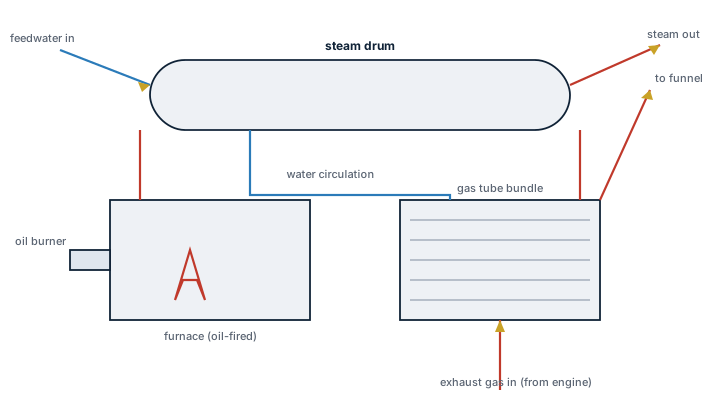
A composite boiler combines an oil-fired furnace and an exhaust gas heating surface inside one shell, so it can raise steam from the main engine's waste heat while under way and switch to oil firing in port or at low load, without running two separate boiler units.
Read more — Composite Boiler explained ▾
What sets a composite boiler apart
A pure exhaust gas economiser only makes steam when the main engine is running hard enough to produce useful exhaust heat, and a pure oil-fired boiler needs its own furnace and burner regardless of engine load. A composite boiler puts both heat sources inside a single pressure vessel: exhaust gas tubes pass through the same steam and water space as the oil-fired section, so the vessel automatically draws steam from whichever source is available, cutting fuel consumption at sea and giving full steam-raising capability in port.
Main components
Oil-fired section
A furnace with a rotary or pressure-jet burner, refractory lining and its own combustion air fan, functioning as a conventional smoke tube or water tube boiler section.
Exhaust gas section
A bank of gas tubes or a gas-side casing routed from the main engine exhaust, arranged so soot blowing and gas-side cleaning can be carried out without shutting down the oil-fired side.
Common steam drum
Both heat sources feed the same steam and water space, so water level control and safety valves cover the composite unit as a single system rather than two.
Soot blowers and gas dampers
Fitted to the exhaust gas passages to control gas-side fouling, with dampers to isolate the exhaust gas section when the main engine is stopped or when its heat is not needed.
Selection and sizing
- Steam demand at sea versus in port, since the split between the two heat sources drives the balance of exhaust gas heating surface against oil-fired capacity.
- Main engine exhaust gas temperature and flow at normal service load, which sets how much of the steam demand the exhaust section can cover unaided.
- Working pressure needed by cargo heating, fuel heating or accommodation services.
- Space and weight in the funnel casing, since routing exhaust gas through the boiler adds backpressure that the main engine maker must approve.
Regulations and class
Class rules cover the pressure vessel design, safety valve capacity and periodic internal and hydraulic testing exactly as for any steam boiler, with the composite unit surveyed as one vessel. SOLAS Ch. II-2 requirements for boiler room fire protection and fuel oil supply arrangements apply to the oil-fired section. Exhaust gas backpressure introduced by the gas-side tube bank is subject to the main engine maker's approved limit and is checked at commissioning and after major gas-side cleaning.
Typical faults
| Fault | Consequence |
|---|---|
| Soot and unburnt deposits building up on exhaust gas tubes | Falling exhaust steam output and rising engine backpressure |
| Uneven water circulation between the two heating sections | Local overheating and tube wastage where circulation is weakest |
| Burner left in poor combustion trim | Carbon build-up on the oil-fired section, reduced efficiency, smoke |
| Gas damper seized or not fully closing | Uncontrolled gas-side cooling, condensation and acid corrosion when the engine is stopped |
What to look for in a supplier
- Class-approved pressure vessel design documentation covering both heat sources as a single approved unit.
- Confirmed compatibility of the exhaust gas backpressure with the specific main engine model fitted.
- Soot blower and gas-side access design that allows cleaning without a full boiler shutdown.
- Spares commonality between the oil-fired burner components and other boilers already on board, where possible.
Log exhaust gas outlet temperature from the boiler alongside engine load, not just boiler pressure, since a rising outlet temperature at constant load is usually the first sign of gas-side fouling long before steam output visibly drops.
Typical Manufacturers
6 manufacturers · 52 models
Alfa Laval
18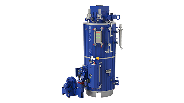
- Dampfkapazität OL
- 12.500–55.000 kg/h (mit BOG-Management)
- Dampfkapazität D
- 25–120 t/h (Tanker-Hauptkessel)
- Designdrücke
- 9 or 18 bar(g)
- Konstruktion
- Zweritrommel (Dampftrommel/Wassertrommel), Membranwände, Generatorröhrenbank
- Rohrsystem
- Gerade Pin-Tubes mit Schwenk-Pins, externe Fallrohre (Aalborg D)
- Brenner-typ
- Oelgefeuert (Standard), Dual-Fuel optional, KBSD/Aalborg-Brenner
- Refraktär
- Minimal im Feuerraum, Isolations- + Formrefraktär an Rohrplatte
- Aalborg OL (12.5-55 t/h, 9/18 bar)
- Aalborg D (25-120 t/h, 18 bar, Tanker-Design)
- Aalborg OM (8-45 t/h, Mittelkapazität)
- Mission OS (bis 6 t/h, Vertical Auxiliary)
- Area: Tube body leakage due to corrosion, pitting, deposits (scale/sludge) or wearCheck: Internal visual inspection of all steam/water tubes; perform pressure test if suspected; seal leaking tube with conical stop valve after steel wire brush cleaning of tube ends. Leaking tubes must be renewed.
- Area: Water level regulation: failure of differential pressure transmitter or feedwater control valve leads to flooding/drying outCheck: Check DP transmitter unit (external reference/variable leg, 4–20 mA output); feedwater control valve functional test; sight glass for cracks, contamination; test alarm function in control unit
- Area: Safety valve failure or incorrect opening/closing pressures — overpressure or inadequate emergency steam reliefCheck: Test two safety valves under full-load steam: pressure build-up 7 min. max. +6% working pressure permissible (water tubes); pop-point of each valve max. ±3% from set pressure; class notation: perform opening + accumulation test under classifier supervision
- Area: Furnace refractory damage (cracks, spalling) or soot/corrosion → heat leaks, furnace instability, drum overheatingCheck: Inspect furnace walls and refractory lining visually (min. 2x/year); check for cracks, moisture, soot deposits. Check lower tube plate (insulation + form refractory). After 3–4 weeks operation: perform blow-down, inspect/clean boiler, remove sludge
- Area: Loss of pressure integrity due to corrosion, cracks, rivets or welds → leakage, operating loss, safety riskCheck: Hydrostatic test: fill boiler with water 21–65 °C (water tubes max. 71 °C). Pressure: 1.5× MAWP (non-entry) or 1.25× MAWP (entry). Secure safety valves with clamps. Check all seal surfaces, rivets, welds for leaks. Class notation: every 2 years (up to 8 years), then annually
- Area: Internal corrosion (water side), scale deposits or fire side soot/flocking → tube wear, heat loss, contaminationCheck: Class survey: water side (steam drum, water drum, all tubes) check for corrosion/cracks/deposits; fire side (furnace, flue gas path) check for soot/flocking (min. 2x/year). Man holes (top/bottom) permit access. If necessary use ultrasonic/endoscope for deeper defects
Type-universal inspection points for Alfa Laval Aalborg oil-fired marine steam boiler (Water Tube / D-Type) (Aalborg + Class/eCFR, 2026-06). Per-model specs not auto-populated.
- Small footprint with vertical orientation fits confined engine‑room spaces.
- Fast start‑up and high part‑load efficiency due to low water content design.
- Optional dual‑fuel capability provides flexibility when oil supply is limited.
- Alfa Laval membrane walls and pin‑tube bank give excellent heat transfer and rapid steam generation.
- Classified by major societies (ABS, DNV GL) and USCG type approved, simplifying regulatory compliance.
- Maximum output of only 6 t/h limits suitability for vessels with high steam demand.
- Primarily oil‑fired; dual‑fuel option adds cost and complexity.
- Composite construction requires strict water treatment to prevent corrosion and scale.
- Pin‑tube bank inspection and cleaning can be more labor‑intensive than fire‑tube designs.
- Not intended for continuous full‑load operation on large tankers or bulk carriers.
- Dampfkapazität OL
- 12.500–55.000 kg/h (mit BOG-Management)
- Dampfkapazität D
- 25–120 t/h (Tanker-Hauptkessel)
- Designdrücke
- 9 or 18 bar(g)
- Konstruktion
- Zweritrommel (Dampftrommel/Wassertrommel), Membranwände, Generatorröhrenbank
- Rohrsystem
- Gerade Pin-Tubes mit Schwenk-Pins, externe Fallrohre (Aalborg D)
- Brenner-typ
- Oelgefeuert (Standard), Dual-Fuel optional, KBSD/Aalborg-Brenner
- Refraktär
- Minimal im Feuerraum, Isolations- + Formrefraktär an Rohrplatte
- Aalborg OL (12.5-55 t/h, 9/18 bar)
- Aalborg D (25-120 t/h, 18 bar, Tanker-Design)
- Aalborg OM (8-45 t/h, Mittelkapazität)
- Mission OS (bis 6 t/h, Vertical Auxiliary)
- Area: Tube body leakage due to corrosion, pitting, deposits (scale/sludge) or wearCheck: Internal visual inspection of all steam/water tubes; perform pressure test if suspected; seal leaking tube with conical stop valve after steel wire brush cleaning of tube ends. Leaking tubes must be renewed.
- Area: Water level regulation: failure of differential pressure transmitter or feedwater control valve leads to flooding/drying outCheck: Check DP transmitter unit (external reference/variable leg, 4–20 mA output); feedwater control valve functional test; sight glass for cracks, contamination; test alarm function in control unit
- Area: Safety valve failure or incorrect opening/closing pressures — overpressure or inadequate emergency steam reliefCheck: Test two safety valves under full-load steam: pressure build-up 7 min. max. +6% working pressure permissible (water tubes); pop-point of each valve max. ±3% from set pressure; class notation: perform opening + accumulation test under classifier supervision
- Area: Furnace refractory damage (cracks, spalling) or soot/corrosion → heat leaks, furnace instability, drum overheatingCheck: Inspect furnace walls and refractory lining visually (min. 2x/year); check for cracks, moisture, soot deposits. Check lower tube plate (insulation + form refractory). After 3–4 weeks operation: perform blow-down, inspect/clean boiler, remove sludge
- Area: Loss of pressure integrity due to corrosion, cracks, rivets or welds → leakage, operating loss, safety riskCheck: Hydrostatic test: fill boiler with water 21–65 °C (water tubes max. 71 °C). Pressure: 1.5× MAWP (non-entry) or 1.25× MAWP (entry). Secure safety valves with clamps. Check all seal surfaces, rivets, welds for leaks. Class notation: every 2 years (up to 8 years), then annually
- Area: Internal corrosion (water side), scale deposits or fire side soot/flocking → tube wear, heat loss, contaminationCheck: Class survey: water side (steam drum, water drum, all tubes) check for corrosion/cracks/deposits; fire side (furnace, flue gas path) check for soot/flocking (min. 2x/year). Man holes (top/bottom) permit access. If necessary use ultrasonic/endoscope for deeper defects
Type-universal inspection points for Alfa Laval Aalborg oil-fired marine steam boiler (Water Tube / D-Type) (Aalborg + Class/eCFR, 2026-06). Per-model specs not auto-populated.
- Integrated dual‑fuel (oil + exhaust gas) capability provides fuel flexibility and BOG utilization.
- High steam output (12.5–120 t/h) suitable for main propulsion boilers on tankers and large bulk carriers.
- Compact D‑type water‑tube construction with membrane walls reduces overall plant footprint.
- Minimal fire‑box refractory lowers weight and simplifies furnace maintenance.
- Design pressure options (9 or 18 bar) match most merchant‑ship steam system requirements.
- Complex control strategy for simultaneous oil and exhaust‑gas operation increases commissioning effort.
- Higher capital cost compared with single‑fuel water‑tube boilers.
- Regular soot‑blowing of the EG section is required to maintain heat transfer efficiency.
- Limited to 9–18 bar design pressure; not suitable for high‑pressure (≥20 bar) applications.
- Tube bundle maintenance can be intensive due to corrosion or scale if water chemistry is poor.
- Dampfkapazität OL
- 12.500–55.000 kg/h (mit BOG-Management)
- Dampfkapazität D
- 25–120 t/h (Tanker-Hauptkessel)
- Designdrücke
- 9 or 18 bar(g)
- Konstruktion
- Zweritrommel (Dampftrommel/Wassertrommel), Membranwände, Generatorröhrenbank
- Rohrsystem
- Gerade Pin-Tubes mit Schwenk-Pins, externe Fallrohre (Aalborg D)
- Brenner-typ
- Oelgefeuert (Standard), Dual-Fuel optional, KBSD/Aalborg-Brenner
- Refraktär
- Minimal im Feuerraum, Isolations- + Formrefraktär an Rohrplatte
- Aalborg OL (12.5-55 t/h, 9/18 bar)
- Aalborg D (25-120 t/h, 18 bar, Tanker-Design)
- Aalborg OM (8-45 t/h, Mittelkapazität)
- Mission OS (bis 6 t/h, Vertical Auxiliary)
- Area: Tube body leakage due to corrosion, pitting, deposits (scale/sludge) or wearCheck: Internal visual inspection of all steam/water tubes; perform pressure test if suspected; seal leaking tube with conical stop valve after steel wire brush cleaning of tube ends. Leaking tubes must be renewed.
- Area: Water level regulation: failure of differential pressure transmitter or feedwater control valve leads to flooding/drying outCheck: Check DP transmitter unit (external reference/variable leg, 4–20 mA output); feedwater control valve functional test; sight glass for cracks, contamination; test alarm function in control unit
- Area: Safety valve failure or incorrect opening/closing pressures — overpressure or inadequate emergency steam reliefCheck: Test two safety valves under full-load steam: pressure build-up 7 min. max. +6% working pressure permissible (water tubes); pop-point of each valve max. ±3% from set pressure; class notation: perform opening + accumulation test under classifier supervision
- Area: Furnace refractory damage (cracks, spalling) or soot/corrosion → heat leaks, furnace instability, drum overheatingCheck: Inspect furnace walls and refractory lining visually (min. 2x/year); check for cracks, moisture, soot deposits. Check lower tube plate (insulation + form refractory). After 3–4 weeks operation: perform blow-down, inspect/clean boiler, remove sludge
- Area: Loss of pressure integrity due to corrosion, cracks, rivets or welds → leakage, operating loss, safety riskCheck: Hydrostatic test: fill boiler with water 21–65 °C (water tubes max. 71 °C). Pressure: 1.5× MAWP (non-entry) or 1.25× MAWP (entry). Secure safety valves with clamps. Check all seal surfaces, rivets, welds for leaks. Class notation: every 2 years (up to 8 years), then annually
- Area: Internal corrosion (water side), scale deposits or fire side soot/flocking → tube wear, heat loss, contaminationCheck: Class survey: water side (steam drum, water drum, all tubes) check for corrosion/cracks/deposits; fire side (furnace, flue gas path) check for soot/flocking (min. 2x/year). Man holes (top/bottom) permit access. If necessary use ultrasonic/endoscope for deeper defects
Type-universal inspection points for Alfa Laval Aalborg oil-fired marine steam boiler (Water Tube / D-Type) (Aalborg + Class/eCFR, 2026-06). Per-model specs not auto-populated.

- Dampfkapazität OL
- 12.500–55.000 kg/h (mit BOG-Management)
- Dampfkapazität D
- 25–120 t/h (Tanker-Hauptkessel)
- Designdrücke
- 9 or 18 bar(g)
- Konstruktion
- Zweritrommel (Dampftrommel/Wassertrommel), Membranwände, Generatorröhrenbank
- Rohrsystem
- Gerade Pin-Tubes mit Schwenk-Pins, externe Fallrohre (Aalborg D)
- Brenner-typ
- Oelgefeuert (Standard), Dual-Fuel optional, KBSD/Aalborg-Brenner
- Refraktär
- Minimal im Feuerraum, Isolations- + Formrefraktär an Rohrplatte
- Aalborg OL (12.5-55 t/h, 9/18 bar)
- Aalborg D (25-120 t/h, 18 bar, Tanker-Design)
- Aalborg OM (8-45 t/h, Mittelkapazität)
- Mission OS (bis 6 t/h, Vertical Auxiliary)
- Area: Tube body leakage due to corrosion, pitting, deposits (scale/sludge) or wearCheck: Internal visual inspection of all steam/water tubes; perform pressure test if suspected; seal leaking tube with conical stop valve after steel wire brush cleaning of tube ends. Leaking tubes must be renewed.
- Area: Water level regulation: failure of differential pressure transmitter or feedwater control valve leads to flooding/drying outCheck: Check DP transmitter unit (external reference/variable leg, 4–20 mA output); feedwater control valve functional test; sight glass for cracks, contamination; test alarm function in control unit
- Area: Safety valve failure or incorrect opening/closing pressures — overpressure or inadequate emergency steam reliefCheck: Test two safety valves under full-load steam: pressure build-up 7 min. max. +6% working pressure permissible (water tubes); pop-point of each valve max. ±3% from set pressure; class notation: perform opening + accumulation test under classifier supervision
- Area: Furnace refractory damage (cracks, spalling) or soot/corrosion → heat leaks, furnace instability, drum overheatingCheck: Inspect furnace walls and refractory lining visually (min. 2x/year); check for cracks, moisture, soot deposits. Check lower tube plate (insulation + form refractory). After 3–4 weeks operation: perform blow-down, inspect/clean boiler, remove sludge
- Area: Loss of pressure integrity due to corrosion, cracks, rivets or welds → leakage, operating loss, safety riskCheck: Hydrostatic test: fill boiler with water 21–65 °C (water tubes max. 71 °C). Pressure: 1.5× MAWP (non-entry) or 1.25× MAWP (entry). Secure safety valves with clamps. Check all seal surfaces, rivets, welds for leaks. Class notation: every 2 years (up to 8 years), then annually
- Area: Internal corrosion (water side), scale deposits or fire side soot/flocking → tube wear, heat loss, contaminationCheck: Class survey: water side (steam drum, water drum, all tubes) check for corrosion/cracks/deposits; fire side (furnace, flue gas path) check for soot/flocking (min. 2x/year). Man holes (top/bottom) permit access. If necessary use ultrasonic/endoscope for deeper defects
Type-universal inspection points for Alfa Laval Aalborg oil-fired marine steam boiler (Water Tube / D-Type) (Aalborg + Class/eCFR, 2026-06). Per-model specs not auto-populated.
- Dampfkapazität OL
- 12.500–55.000 kg/h (mit BOG-Management)
- Dampfkapazität D
- 25–120 t/h (Tanker-Hauptkessel)
- Designdrücke
- 9 or 18 bar(g)
- Konstruktion
- Zweritrommel (Dampftrommel/Wassertrommel), Membranwände, Generatorröhrenbank
- Rohrsystem
- Gerade Pin-Tubes mit Schwenk-Pins, externe Fallrohre (Aalborg D)
- Brenner-typ
- Oelgefeuert (Standard), Dual-Fuel optional, KBSD/Aalborg-Brenner
- Refraktär
- Minimal im Feuerraum, Isolations- + Formrefraktär an Rohrplatte
- Aalborg OL (12.5-55 t/h, 9/18 bar)
- Aalborg D (25-120 t/h, 18 bar, Tanker-Design)
- Aalborg OM (8-45 t/h, Mittelkapazität)
- Mission OS (bis 6 t/h, Vertical Auxiliary)
- Area: Tube body leakage due to corrosion, pitting, deposits (scale/sludge) or wearCheck: Internal visual inspection of all steam/water tubes; perform pressure test if suspected; seal leaking tube with conical stop valve after steel wire brush cleaning of tube ends. Leaking tubes must be renewed.
- Area: Water level regulation: failure of differential pressure transmitter or feedwater control valve leads to flooding/drying outCheck: Check DP transmitter unit (external reference/variable leg, 4–20 mA output); feedwater control valve functional test; sight glass for cracks, contamination; test alarm function in control unit
- Area: Safety valve failure or incorrect opening/closing pressures — overpressure or inadequate emergency steam reliefCheck: Test two safety valves under full-load steam: pressure build-up 7 min. max. +6% working pressure permissible (water tubes); pop-point of each valve max. ±3% from set pressure; class notation: perform opening + accumulation test under classifier supervision
- Area: Furnace refractory damage (cracks, spalling) or soot/corrosion → heat leaks, furnace instability, drum overheatingCheck: Inspect furnace walls and refractory lining visually (min. 2x/year); check for cracks, moisture, soot deposits. Check lower tube plate (insulation + form refractory). After 3–4 weeks operation: perform blow-down, inspect/clean boiler, remove sludge
- Area: Loss of pressure integrity due to corrosion, cracks, rivets or welds → leakage, operating loss, safety riskCheck: Hydrostatic test: fill boiler with water 21–65 °C (water tubes max. 71 °C). Pressure: 1.5× MAWP (non-entry) or 1.25× MAWP (entry). Secure safety valves with clamps. Check all seal surfaces, rivets, welds for leaks. Class notation: every 2 years (up to 8 years), then annually
- Area: Internal corrosion (water side), scale deposits or fire side soot/flocking → tube wear, heat loss, contaminationCheck: Class survey: water side (steam drum, water drum, all tubes) check for corrosion/cracks/deposits; fire side (furnace, flue gas path) check for soot/flocking (min. 2x/year). Man holes (top/bottom) permit access. If necessary use ultrasonic/endoscope for deeper defects
Type-universal inspection points for Alfa Laval Aalborg oil-fired marine steam boiler (Water Tube / D-Type) (Aalborg + Class/eCFR, 2026-06). Per-model specs not auto-populated.
- Dampfkapazität OL
- 12.500–55.000 kg/h (mit BOG-Management)
- Dampfkapazität D
- 25–120 t/h (Tanker-Hauptkessel)
- Designdrücke
- 9 or 18 bar(g)
- Konstruktion
- Zweritrommel (Dampftrommel/Wassertrommel), Membranwände, Generatorröhrenbank
- Rohrsystem
- Gerade Pin-Tubes mit Schwenk-Pins, externe Fallrohre (Aalborg D)
- Brenner-typ
- Oelgefeuert (Standard), Dual-Fuel optional, KBSD/Aalborg-Brenner
- Refraktär
- Minimal im Feuerraum, Isolations- + Formrefraktär an Rohrplatte
- Aalborg OL (12.5-55 t/h, 9/18 bar)
- Aalborg D (25-120 t/h, 18 bar, Tanker-Design)
- Aalborg OM (8-45 t/h, Mittelkapazität)
- Mission OS (bis 6 t/h, Vertical Auxiliary)
- Area: Tube body leakage due to corrosion, pitting, deposits (scale/sludge) or wearCheck: Internal visual inspection of all steam/water tubes; perform pressure test if suspected; seal leaking tube with conical stop valve after steel wire brush cleaning of tube ends. Leaking tubes must be renewed.
- Area: Water level regulation: failure of differential pressure transmitter or feedwater control valve leads to flooding/drying outCheck: Check DP transmitter unit (external reference/variable leg, 4–20 mA output); feedwater control valve functional test; sight glass for cracks, contamination; test alarm function in control unit
- Area: Safety valve failure or incorrect opening/closing pressures — overpressure or inadequate emergency steam reliefCheck: Test two safety valves under full-load steam: pressure build-up 7 min. max. +6% working pressure permissible (water tubes); pop-point of each valve max. ±3% from set pressure; class notation: perform opening + accumulation test under classifier supervision
- Area: Furnace refractory damage (cracks, spalling) or soot/corrosion → heat leaks, furnace instability, drum overheatingCheck: Inspect furnace walls and refractory lining visually (min. 2x/year); check for cracks, moisture, soot deposits. Check lower tube plate (insulation + form refractory). After 3–4 weeks operation: perform blow-down, inspect/clean boiler, remove sludge
- Area: Loss of pressure integrity due to corrosion, cracks, rivets or welds → leakage, operating loss, safety riskCheck: Hydrostatic test: fill boiler with water 21–65 °C (water tubes max. 71 °C). Pressure: 1.5× MAWP (non-entry) or 1.25× MAWP (entry). Secure safety valves with clamps. Check all seal surfaces, rivets, welds for leaks. Class notation: every 2 years (up to 8 years), then annually
- Area: Internal corrosion (water side), scale deposits or fire side soot/flocking → tube wear, heat loss, contaminationCheck: Class survey: water side (steam drum, water drum, all tubes) check for corrosion/cracks/deposits; fire side (furnace, flue gas path) check for soot/flocking (min. 2x/year). Man holes (top/bottom) permit access. If necessary use ultrasonic/endoscope for deeper defects
Type-universal inspection points for Alfa Laval Aalborg oil-fired marine steam boiler (Water Tube / D-Type) (Aalborg + Class/eCFR, 2026-06). Per-model specs not auto-populated.
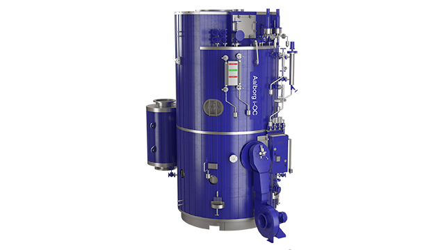
- Dampfkapazität OL
- 12.500–55.000 kg/h (mit BOG-Management)
- Dampfkapazität D
- 25–120 t/h (Tanker-Hauptkessel)
- Designdrücke
- 9 or 18 bar(g)
- Konstruktion
- Zweritrommel (Dampftrommel/Wassertrommel), Membranwände, Generatorröhrenbank
- Rohrsystem
- Gerade Pin-Tubes mit Schwenk-Pins, externe Fallrohre (Aalborg D)
- Brenner-typ
- Oelgefeuert (Standard), Dual-Fuel optional, KBSD/Aalborg-Brenner
- Refraktär
- Minimal im Feuerraum, Isolations- + Formrefraktär an Rohrplatte
- Aalborg OL (12.5-55 t/h, 9/18 bar)
- Aalborg D (25-120 t/h, 18 bar, Tanker-Design)
- Aalborg OM (8-45 t/h, Mittelkapazität)
- Mission OS (bis 6 t/h, Vertical Auxiliary)
- Area: Tube body leakage due to corrosion, pitting, deposits (scale/sludge) or wearCheck: Internal visual inspection of all steam/water tubes; perform pressure test if suspected; seal leaking tube with conical stop valve after steel wire brush cleaning of tube ends. Leaking tubes must be renewed.
- Area: Water level regulation: failure of differential pressure transmitter or feedwater control valve leads to flooding/drying outCheck: Check DP transmitter unit (external reference/variable leg, 4–20 mA output); feedwater control valve functional test; sight glass for cracks, contamination; test alarm function in control unit
- Area: Safety valve failure or incorrect opening/closing pressures — overpressure or inadequate emergency steam reliefCheck: Test two safety valves under full-load steam: pressure build-up 7 min. max. +6% working pressure permissible (water tubes); pop-point of each valve max. ±3% from set pressure; class notation: perform opening + accumulation test under classifier supervision
- Area: Furnace refractory damage (cracks, spalling) or soot/corrosion → heat leaks, furnace instability, drum overheatingCheck: Inspect furnace walls and refractory lining visually (min. 2x/year); check for cracks, moisture, soot deposits. Check lower tube plate (insulation + form refractory). After 3–4 weeks operation: perform blow-down, inspect/clean boiler, remove sludge
- Area: Loss of pressure integrity due to corrosion, cracks, rivets or welds → leakage, operating loss, safety riskCheck: Hydrostatic test: fill boiler with water 21–65 °C (water tubes max. 71 °C). Pressure: 1.5× MAWP (non-entry) or 1.25× MAWP (entry). Secure safety valves with clamps. Check all seal surfaces, rivets, welds for leaks. Class notation: every 2 years (up to 8 years), then annually
- Area: Internal corrosion (water side), scale deposits or fire side soot/flocking → tube wear, heat loss, contaminationCheck: Class survey: water side (steam drum, water drum, all tubes) check for corrosion/cracks/deposits; fire side (furnace, flue gas path) check for soot/flocking (min. 2x/year). Man holes (top/bottom) permit access. If necessary use ultrasonic/endoscope for deeper defects
Type-universal inspection points for Alfa Laval Aalborg oil-fired marine steam boiler (Water Tube / D-Type) (Aalborg + Class/eCFR, 2026-06). Per-model specs not auto-populated.
- Dampfkapazität OL
- 12.500–55.000 kg/h (mit BOG-Management)
- Dampfkapazität D
- 25–120 t/h (Tanker-Hauptkessel)
- Designdrücke
- 9 or 18 bar(g)
- Konstruktion
- Zweritrommel (Dampftrommel/Wassertrommel), Membranwände, Generatorröhrenbank
- Rohrsystem
- Gerade Pin-Tubes mit Schwenk-Pins, externe Fallrohre (Aalborg D)
- Brenner-typ
- Oelgefeuert (Standard), Dual-Fuel optional, KBSD/Aalborg-Brenner
- Refraktär
- Minimal im Feuerraum, Isolations- + Formrefraktär an Rohrplatte
- Aalborg OL (12.5-55 t/h, 9/18 bar)
- Aalborg D (25-120 t/h, 18 bar, Tanker-Design)
- Aalborg OM (8-45 t/h, Mittelkapazität)
- Mission OS (bis 6 t/h, Vertical Auxiliary)
- Area: Tube body leakage due to corrosion, pitting, deposits (scale/sludge) or wearCheck: Internal visual inspection of all steam/water tubes; perform pressure test if suspected; seal leaking tube with conical stop valve after steel wire brush cleaning of tube ends. Leaking tubes must be renewed.
- Area: Water level regulation: failure of differential pressure transmitter or feedwater control valve leads to flooding/drying outCheck: Check DP transmitter unit (external reference/variable leg, 4–20 mA output); feedwater control valve functional test; sight glass for cracks, contamination; test alarm function in control unit
- Area: Safety valve failure or incorrect opening/closing pressures — overpressure or inadequate emergency steam reliefCheck: Test two safety valves under full-load steam: pressure build-up 7 min. max. +6% working pressure permissible (water tubes); pop-point of each valve max. ±3% from set pressure; class notation: perform opening + accumulation test under classifier supervision
- Area: Furnace refractory damage (cracks, spalling) or soot/corrosion → heat leaks, furnace instability, drum overheatingCheck: Inspect furnace walls and refractory lining visually (min. 2x/year); check for cracks, moisture, soot deposits. Check lower tube plate (insulation + form refractory). After 3–4 weeks operation: perform blow-down, inspect/clean boiler, remove sludge
- Area: Loss of pressure integrity due to corrosion, cracks, rivets or welds → leakage, operating loss, safety riskCheck: Hydrostatic test: fill boiler with water 21–65 °C (water tubes max. 71 °C). Pressure: 1.5× MAWP (non-entry) or 1.25× MAWP (entry). Secure safety valves with clamps. Check all seal surfaces, rivets, welds for leaks. Class notation: every 2 years (up to 8 years), then annually
- Area: Internal corrosion (water side), scale deposits or fire side soot/flocking → tube wear, heat loss, contaminationCheck: Class survey: water side (steam drum, water drum, all tubes) check for corrosion/cracks/deposits; fire side (furnace, flue gas path) check for soot/flocking (min. 2x/year). Man holes (top/bottom) permit access. If necessary use ultrasonic/endoscope for deeper defects
Type-universal inspection points for Alfa Laval Aalborg oil-fired marine steam boiler (Water Tube / D-Type) (Aalborg + Class/eCFR, 2026-06). Per-model specs not auto-populated.
- Dampfkapazität OL
- 12.500–55.000 kg/h (mit BOG-Management)
- Dampfkapazität D
- 25–120 t/h (Tanker-Hauptkessel)
- Designdrücke
- 9 or 18 bar(g)
- Konstruktion
- Zweritrommel (Dampftrommel/Wassertrommel), Membranwände, Generatorröhrenbank
- Rohrsystem
- Gerade Pin-Tubes mit Schwenk-Pins, externe Fallrohre (Aalborg D)
- Brenner-typ
- Oelgefeuert (Standard), Dual-Fuel optional, KBSD/Aalborg-Brenner
- Refraktär
- Minimal im Feuerraum, Isolations- + Formrefraktär an Rohrplatte
- Aalborg OL (12.5-55 t/h, 9/18 bar)
- Aalborg D (25-120 t/h, 18 bar, Tanker-Design)
- Aalborg OM (8-45 t/h, Mittelkapazität)
- Mission OS (bis 6 t/h, Vertical Auxiliary)
- Area: Tube body leakage due to corrosion, pitting, deposits (scale/sludge) or wearCheck: Internal visual inspection of all steam/water tubes; perform pressure test if suspected; seal leaking tube with conical stop valve after steel wire brush cleaning of tube ends. Leaking tubes must be renewed.
- Area: Water level regulation: failure of differential pressure transmitter or feedwater control valve leads to flooding/drying outCheck: Check DP transmitter unit (external reference/variable leg, 4–20 mA output); feedwater control valve functional test; sight glass for cracks, contamination; test alarm function in control unit
- Area: Safety valve failure or incorrect opening/closing pressures — overpressure or inadequate emergency steam reliefCheck: Test two safety valves under full-load steam: pressure build-up 7 min. max. +6% working pressure permissible (water tubes); pop-point of each valve max. ±3% from set pressure; class notation: perform opening + accumulation test under classifier supervision
- Area: Furnace refractory damage (cracks, spalling) or soot/corrosion → heat leaks, furnace instability, drum overheatingCheck: Inspect furnace walls and refractory lining visually (min. 2x/year); check for cracks, moisture, soot deposits. Check lower tube plate (insulation + form refractory). After 3–4 weeks operation: perform blow-down, inspect/clean boiler, remove sludge
- Area: Loss of pressure integrity due to corrosion, cracks, rivets or welds → leakage, operating loss, safety riskCheck: Hydrostatic test: fill boiler with water 21–65 °C (water tubes max. 71 °C). Pressure: 1.5× MAWP (non-entry) or 1.25× MAWP (entry). Secure safety valves with clamps. Check all seal surfaces, rivets, welds for leaks. Class notation: every 2 years (up to 8 years), then annually
- Area: Internal corrosion (water side), scale deposits or fire side soot/flocking → tube wear, heat loss, contaminationCheck: Class survey: water side (steam drum, water drum, all tubes) check for corrosion/cracks/deposits; fire side (furnace, flue gas path) check for soot/flocking (min. 2x/year). Man holes (top/bottom) permit access. If necessary use ultrasonic/endoscope for deeper defects
Type-universal inspection points for Alfa Laval Aalborg oil-fired marine steam boiler (Water Tube / D-Type) (Aalborg + Class/eCFR, 2026-06). Per-model specs not auto-populated.
- Dampfkapazität OL
- 12.500–55.000 kg/h (mit BOG-Management)
- Dampfkapazität D
- 25–120 t/h (Tanker-Hauptkessel)
- Designdrücke
- 9 or 18 bar(g)
- Konstruktion
- Zweritrommel (Dampftrommel/Wassertrommel), Membranwände, Generatorröhrenbank
- Rohrsystem
- Gerade Pin-Tubes mit Schwenk-Pins, externe Fallrohre (Aalborg D)
- Brenner-typ
- Oelgefeuert (Standard), Dual-Fuel optional, KBSD/Aalborg-Brenner
- Refraktär
- Minimal im Feuerraum, Isolations- + Formrefraktär an Rohrplatte
- Aalborg OL (12.5-55 t/h, 9/18 bar)
- Aalborg D (25-120 t/h, 18 bar, Tanker-Design)
- Aalborg OM (8-45 t/h, Mittelkapazität)
- Mission OS (bis 6 t/h, Vertical Auxiliary)
- Area: Tube body leakage due to corrosion, pitting, deposits (scale/sludge) or wearCheck: Internal visual inspection of all steam/water tubes; perform pressure test if suspected; seal leaking tube with conical stop valve after steel wire brush cleaning of tube ends. Leaking tubes must be renewed.
- Area: Water level regulation: failure of differential pressure transmitter or feedwater control valve leads to flooding/drying outCheck: Check DP transmitter unit (external reference/variable leg, 4–20 mA output); feedwater control valve functional test; sight glass for cracks, contamination; test alarm function in control unit
- Area: Safety valve failure or incorrect opening/closing pressures — overpressure or inadequate emergency steam reliefCheck: Test two safety valves under full-load steam: pressure build-up 7 min. max. +6% working pressure permissible (water tubes); pop-point of each valve max. ±3% from set pressure; class notation: perform opening + accumulation test under classifier supervision
- Area: Furnace refractory damage (cracks, spalling) or soot/corrosion → heat leaks, furnace instability, drum overheatingCheck: Inspect furnace walls and refractory lining visually (min. 2x/year); check for cracks, moisture, soot deposits. Check lower tube plate (insulation + form refractory). After 3–4 weeks operation: perform blow-down, inspect/clean boiler, remove sludge
- Area: Loss of pressure integrity due to corrosion, cracks, rivets or welds → leakage, operating loss, safety riskCheck: Hydrostatic test: fill boiler with water 21–65 °C (water tubes max. 71 °C). Pressure: 1.5× MAWP (non-entry) or 1.25× MAWP (entry). Secure safety valves with clamps. Check all seal surfaces, rivets, welds for leaks. Class notation: every 2 years (up to 8 years), then annually
- Area: Internal corrosion (water side), scale deposits or fire side soot/flocking → tube wear, heat loss, contaminationCheck: Class survey: water side (steam drum, water drum, all tubes) check for corrosion/cracks/deposits; fire side (furnace, flue gas path) check for soot/flocking (min. 2x/year). Man holes (top/bottom) permit access. If necessary use ultrasonic/endoscope for deeper defects
Type-universal inspection points for Alfa Laval Aalborg oil-fired marine steam boiler (Water Tube / D-Type) (Aalborg + Class/eCFR, 2026-06). Per-model specs not auto-populated.
- Dampfkapazität OL
- 12.500–55.000 kg/h (mit BOG-Management)
- Dampfkapazität D
- 25–120 t/h (Tanker-Hauptkessel)
- Designdrücke
- 9 or 18 bar(g)
- Konstruktion
- Zweritrommel (Dampftrommel/Wassertrommel), Membranwände, Generatorröhrenbank
- Rohrsystem
- Gerade Pin-Tubes mit Schwenk-Pins, externe Fallrohre (Aalborg D)
- Brenner-typ
- Oelgefeuert (Standard), Dual-Fuel optional, KBSD/Aalborg-Brenner
- Refraktär
- Minimal im Feuerraum, Isolations- + Formrefraktär an Rohrplatte
- Aalborg OL (12.5-55 t/h, 9/18 bar)
- Aalborg D (25-120 t/h, 18 bar, Tanker-Design)
- Aalborg OM (8-45 t/h, Mittelkapazität)
- Mission OS (bis 6 t/h, Vertical Auxiliary)
- Area: Tube body leakage due to corrosion, pitting, deposits (scale/sludge) or wearCheck: Internal visual inspection of all steam/water tubes; perform pressure test if suspected; seal leaking tube with conical stop valve after steel wire brush cleaning of tube ends. Leaking tubes must be renewed.
- Area: Water level regulation: failure of differential pressure transmitter or feedwater control valve leads to flooding/drying outCheck: Check DP transmitter unit (external reference/variable leg, 4–20 mA output); feedwater control valve functional test; sight glass for cracks, contamination; test alarm function in control unit
- Area: Safety valve failure or incorrect opening/closing pressures — overpressure or inadequate emergency steam reliefCheck: Test two safety valves under full-load steam: pressure build-up 7 min. max. +6% working pressure permissible (water tubes); pop-point of each valve max. ±3% from set pressure; class notation: perform opening + accumulation test under classifier supervision
- Area: Furnace refractory damage (cracks, spalling) or soot/corrosion → heat leaks, furnace instability, drum overheatingCheck: Inspect furnace walls and refractory lining visually (min. 2x/year); check for cracks, moisture, soot deposits. Check lower tube plate (insulation + form refractory). After 3–4 weeks operation: perform blow-down, inspect/clean boiler, remove sludge
- Area: Loss of pressure integrity due to corrosion, cracks, rivets or welds → leakage, operating loss, safety riskCheck: Hydrostatic test: fill boiler with water 21–65 °C (water tubes max. 71 °C). Pressure: 1.5× MAWP (non-entry) or 1.25× MAWP (entry). Secure safety valves with clamps. Check all seal surfaces, rivets, welds for leaks. Class notation: every 2 years (up to 8 years), then annually
- Area: Internal corrosion (water side), scale deposits or fire side soot/flocking → tube wear, heat loss, contaminationCheck: Class survey: water side (steam drum, water drum, all tubes) check for corrosion/cracks/deposits; fire side (furnace, flue gas path) check for soot/flocking (min. 2x/year). Man holes (top/bottom) permit access. If necessary use ultrasonic/endoscope for deeper defects
Type-universal inspection points for Alfa Laval Aalborg oil-fired marine steam boiler (Water Tube / D-Type) (Aalborg + Class/eCFR, 2026-06). Per-model specs not auto-populated.
- Dampfkapazität OL
- 12.500–55.000 kg/h (mit BOG-Management)
- Dampfkapazität D
- 25–120 t/h (Tanker-Hauptkessel)
- Designdrücke
- 9 or 18 bar(g)
- Konstruktion
- Zweritrommel (Dampftrommel/Wassertrommel), Membranwände, Generatorröhrenbank
- Rohrsystem
- Gerade Pin-Tubes mit Schwenk-Pins, externe Fallrohre (Aalborg D)
- Brenner-typ
- Oelgefeuert (Standard), Dual-Fuel optional, KBSD/Aalborg-Brenner
- Refraktär
- Minimal im Feuerraum, Isolations- + Formrefraktär an Rohrplatte
- Aalborg OL (12.5-55 t/h, 9/18 bar)
- Aalborg D (25-120 t/h, 18 bar, Tanker-Design)
- Aalborg OM (8-45 t/h, Mittelkapazität)
- Mission OS (bis 6 t/h, Vertical Auxiliary)
- Area: Tube body leakage due to corrosion, pitting, deposits (scale/sludge) or wearCheck: Internal visual inspection of all steam/water tubes; perform pressure test if suspected; seal leaking tube with conical stop valve after steel wire brush cleaning of tube ends. Leaking tubes must be renewed.
- Area: Water level regulation: failure of differential pressure transmitter or feedwater control valve leads to flooding/drying outCheck: Check DP transmitter unit (external reference/variable leg, 4–20 mA output); feedwater control valve functional test; sight glass for cracks, contamination; test alarm function in control unit
- Area: Safety valve failure or incorrect opening/closing pressures — overpressure or inadequate emergency steam reliefCheck: Test two safety valves under full-load steam: pressure build-up 7 min. max. +6% working pressure permissible (water tubes); pop-point of each valve max. ±3% from set pressure; class notation: perform opening + accumulation test under classifier supervision
- Area: Furnace refractory damage (cracks, spalling) or soot/corrosion → heat leaks, furnace instability, drum overheatingCheck: Inspect furnace walls and refractory lining visually (min. 2x/year); check for cracks, moisture, soot deposits. Check lower tube plate (insulation + form refractory). After 3–4 weeks operation: perform blow-down, inspect/clean boiler, remove sludge
- Area: Loss of pressure integrity due to corrosion, cracks, rivets or welds → leakage, operating loss, safety riskCheck: Hydrostatic test: fill boiler with water 21–65 °C (water tubes max. 71 °C). Pressure: 1.5× MAWP (non-entry) or 1.25× MAWP (entry). Secure safety valves with clamps. Check all seal surfaces, rivets, welds for leaks. Class notation: every 2 years (up to 8 years), then annually
- Area: Internal corrosion (water side), scale deposits or fire side soot/flocking → tube wear, heat loss, contaminationCheck: Class survey: water side (steam drum, water drum, all tubes) check for corrosion/cracks/deposits; fire side (furnace, flue gas path) check for soot/flocking (min. 2x/year). Man holes (top/bottom) permit access. If necessary use ultrasonic/endoscope for deeper defects
Type-universal inspection points for Alfa Laval Aalborg oil-fired marine steam boiler (Water Tube / D-Type) (Aalborg + Class/eCFR, 2026-06). Per-model specs not auto-populated.
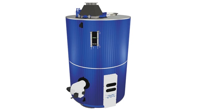
- Dampfkapazität OL
- 12.500–55.000 kg/h (mit BOG-Management)
- Dampfkapazität D
- 25–120 t/h (Tanker-Hauptkessel)
- Designdrücke
- 9 or 18 bar(g)
- Konstruktion
- Zweritrommel (Dampftrommel/Wassertrommel), Membranwände, Generatorröhrenbank
- Rohrsystem
- Gerade Pin-Tubes mit Schwenk-Pins, externe Fallrohre (Aalborg D)
- Brenner-typ
- Oelgefeuert (Standard), Dual-Fuel optional, KBSD/Aalborg-Brenner
- Refraktär
- Minimal im Feuerraum, Isolations- + Formrefraktär an Rohrplatte
- Aalborg OL (12.5-55 t/h, 9/18 bar)
- Aalborg D (25-120 t/h, 18 bar, Tanker-Design)
- Aalborg OM (8-45 t/h, Mittelkapazität)
- Mission OS (bis 6 t/h, Vertical Auxiliary)
- Area: Tube body leakage due to corrosion, pitting, deposits (scale/sludge) or wearCheck: Internal visual inspection of all steam/water tubes; perform pressure test if suspected; seal leaking tube with conical stop valve after steel wire brush cleaning of tube ends. Leaking tubes must be renewed.
- Area: Water level regulation: failure of differential pressure transmitter or feedwater control valve leads to flooding/drying outCheck: Check DP transmitter unit (external reference/variable leg, 4–20 mA output); feedwater control valve functional test; sight glass for cracks, contamination; test alarm function in control unit
- Area: Safety valve failure or incorrect opening/closing pressures — overpressure or inadequate emergency steam reliefCheck: Test two safety valves under full-load steam: pressure build-up 7 min. max. +6% working pressure permissible (water tubes); pop-point of each valve max. ±3% from set pressure; class notation: perform opening + accumulation test under classifier supervision
- Area: Furnace refractory damage (cracks, spalling) or soot/corrosion → heat leaks, furnace instability, drum overheatingCheck: Inspect furnace walls and refractory lining visually (min. 2x/year); check for cracks, moisture, soot deposits. Check lower tube plate (insulation + form refractory). After 3–4 weeks operation: perform blow-down, inspect/clean boiler, remove sludge
- Area: Loss of pressure integrity due to corrosion, cracks, rivets or welds → leakage, operating loss, safety riskCheck: Hydrostatic test: fill boiler with water 21–65 °C (water tubes max. 71 °C). Pressure: 1.5× MAWP (non-entry) or 1.25× MAWP (entry). Secure safety valves with clamps. Check all seal surfaces, rivets, welds for leaks. Class notation: every 2 years (up to 8 years), then annually
- Area: Internal corrosion (water side), scale deposits or fire side soot/flocking → tube wear, heat loss, contaminationCheck: Class survey: water side (steam drum, water drum, all tubes) check for corrosion/cracks/deposits; fire side (furnace, flue gas path) check for soot/flocking (min. 2x/year). Man holes (top/bottom) permit access. If necessary use ultrasonic/endoscope for deeper defects
Type-universal inspection points for Alfa Laval Aalborg oil-fired marine steam boiler (Water Tube / D-Type) (Aalborg + Class/eCFR, 2026-06). Per-model specs not auto-populated.
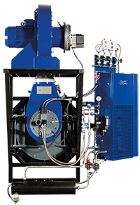
- Dampfkapazität OL
- 12.500–55.000 kg/h (mit BOG-Management)
- Dampfkapazität D
- 25–120 t/h (Tanker-Hauptkessel)
- Designdrücke
- 9 or 18 bar(g)
- Konstruktion
- Zweritrommel (Dampftrommel/Wassertrommel), Membranwände, Generatorröhrenbank
- Rohrsystem
- Gerade Pin-Tubes mit Schwenk-Pins, externe Fallrohre (Aalborg D)
- Brenner-typ
- Oelgefeuert (Standard), Dual-Fuel optional, KBSD/Aalborg-Brenner
- Refraktär
- Minimal im Feuerraum, Isolations- + Formrefraktär an Rohrplatte
- Aalborg OL (12.5-55 t/h, 9/18 bar)
- Aalborg D (25-120 t/h, 18 bar, Tanker-Design)
- Aalborg OM (8-45 t/h, Mittelkapazität)
- Mission OS (bis 6 t/h, Vertical Auxiliary)
- Area: Tube body leakage due to corrosion, pitting, deposits (scale/sludge) or wearCheck: Internal visual inspection of all steam/water tubes; perform pressure test if suspected; seal leaking tube with conical stop valve after steel wire brush cleaning of tube ends. Leaking tubes must be renewed.
- Area: Water level regulation: failure of differential pressure transmitter or feedwater control valve leads to flooding/drying outCheck: Check DP transmitter unit (external reference/variable leg, 4–20 mA output); feedwater control valve functional test; sight glass for cracks, contamination; test alarm function in control unit
- Area: Safety valve failure or incorrect opening/closing pressures — overpressure or inadequate emergency steam reliefCheck: Test two safety valves under full-load steam: pressure build-up 7 min. max. +6% working pressure permissible (water tubes); pop-point of each valve max. ±3% from set pressure; class notation: perform opening + accumulation test under classifier supervision
- Area: Furnace refractory damage (cracks, spalling) or soot/corrosion → heat leaks, furnace instability, drum overheatingCheck: Inspect furnace walls and refractory lining visually (min. 2x/year); check for cracks, moisture, soot deposits. Check lower tube plate (insulation + form refractory). After 3–4 weeks operation: perform blow-down, inspect/clean boiler, remove sludge
- Area: Loss of pressure integrity due to corrosion, cracks, rivets or welds → leakage, operating loss, safety riskCheck: Hydrostatic test: fill boiler with water 21–65 °C (water tubes max. 71 °C). Pressure: 1.5× MAWP (non-entry) or 1.25× MAWP (entry). Secure safety valves with clamps. Check all seal surfaces, rivets, welds for leaks. Class notation: every 2 years (up to 8 years), then annually
- Area: Internal corrosion (water side), scale deposits or fire side soot/flocking → tube wear, heat loss, contaminationCheck: Class survey: water side (steam drum, water drum, all tubes) check for corrosion/cracks/deposits; fire side (furnace, flue gas path) check for soot/flocking (min. 2x/year). Man holes (top/bottom) permit access. If necessary use ultrasonic/endoscope for deeper defects
Type-universal inspection points for Alfa Laval Aalborg oil-fired marine steam boiler (Water Tube / D-Type) (Aalborg + Class/eCFR, 2026-06). Per-model specs not auto-populated.
- Dampfkapazität OL
- 12.500–55.000 kg/h (mit BOG-Management)
- Dampfkapazität D
- 25–120 t/h (Tanker-Hauptkessel)
- Designdrücke
- 9 or 18 bar(g)
- Konstruktion
- Zweritrommel (Dampftrommel/Wassertrommel), Membranwände, Generatorröhrenbank
- Rohrsystem
- Gerade Pin-Tubes mit Schwenk-Pins, externe Fallrohre (Aalborg D)
- Brenner-typ
- Oelgefeuert (Standard), Dual-Fuel optional, KBSD/Aalborg-Brenner
- Refraktär
- Minimal im Feuerraum, Isolations- + Formrefraktär an Rohrplatte
- Aalborg OL (12.5-55 t/h, 9/18 bar)
- Aalborg D (25-120 t/h, 18 bar, Tanker-Design)
- Aalborg OM (8-45 t/h, Mittelkapazität)
- Mission OS (bis 6 t/h, Vertical Auxiliary)
- Area: Tube body leakage due to corrosion, pitting, deposits (scale/sludge) or wearCheck: Internal visual inspection of all steam/water tubes; perform pressure test if suspected; seal leaking tube with conical stop valve after steel wire brush cleaning of tube ends. Leaking tubes must be renewed.
- Area: Water level regulation: failure of differential pressure transmitter or feedwater control valve leads to flooding/drying outCheck: Check DP transmitter unit (external reference/variable leg, 4–20 mA output); feedwater control valve functional test; sight glass for cracks, contamination; test alarm function in control unit
- Area: Safety valve failure or incorrect opening/closing pressures — overpressure or inadequate emergency steam reliefCheck: Test two safety valves under full-load steam: pressure build-up 7 min. max. +6% working pressure permissible (water tubes); pop-point of each valve max. ±3% from set pressure; class notation: perform opening + accumulation test under classifier supervision
- Area: Furnace refractory damage (cracks, spalling) or soot/corrosion → heat leaks, furnace instability, drum overheatingCheck: Inspect furnace walls and refractory lining visually (min. 2x/year); check for cracks, moisture, soot deposits. Check lower tube plate (insulation + form refractory). After 3–4 weeks operation: perform blow-down, inspect/clean boiler, remove sludge
- Area: Loss of pressure integrity due to corrosion, cracks, rivets or welds → leakage, operating loss, safety riskCheck: Hydrostatic test: fill boiler with water 21–65 °C (water tubes max. 71 °C). Pressure: 1.5× MAWP (non-entry) or 1.25× MAWP (entry). Secure safety valves with clamps. Check all seal surfaces, rivets, welds for leaks. Class notation: every 2 years (up to 8 years), then annually
- Area: Internal corrosion (water side), scale deposits or fire side soot/flocking → tube wear, heat loss, contaminationCheck: Class survey: water side (steam drum, water drum, all tubes) check for corrosion/cracks/deposits; fire side (furnace, flue gas path) check for soot/flocking (min. 2x/year). Man holes (top/bottom) permit access. If necessary use ultrasonic/endoscope for deeper defects
Type-universal inspection points for Alfa Laval Aalborg oil-fired marine steam boiler (Water Tube / D-Type) (Aalborg + Class/eCFR, 2026-06). Per-model specs not auto-populated.
- Dampfkapazität OL
- 12.500–55.000 kg/h (mit BOG-Management)
- Dampfkapazität D
- 25–120 t/h (Tanker-Hauptkessel)
- Designdrücke
- 9 or 18 bar(g)
- Konstruktion
- Zweritrommel (Dampftrommel/Wassertrommel), Membranwände, Generatorröhrenbank
- Rohrsystem
- Gerade Pin-Tubes mit Schwenk-Pins, externe Fallrohre (Aalborg D)
- Brenner-typ
- Oelgefeuert (Standard), Dual-Fuel optional, KBSD/Aalborg-Brenner
- Refraktär
- Minimal im Feuerraum, Isolations- + Formrefraktär an Rohrplatte
- Aalborg OL (12.5-55 t/h, 9/18 bar)
- Aalborg D (25-120 t/h, 18 bar, Tanker-Design)
- Aalborg OM (8-45 t/h, Mittelkapazität)
- Mission OS (bis 6 t/h, Vertical Auxiliary)
- Area: Tube body leakage due to corrosion, pitting, deposits (scale/sludge) or wearCheck: Internal visual inspection of all steam/water tubes; perform pressure test if suspected; seal leaking tube with conical stop valve after steel wire brush cleaning of tube ends. Leaking tubes must be renewed.
- Area: Water level regulation: failure of differential pressure transmitter or feedwater control valve leads to flooding/drying outCheck: Check DP transmitter unit (external reference/variable leg, 4–20 mA output); feedwater control valve functional test; sight glass for cracks, contamination; test alarm function in control unit
- Area: Safety valve failure or incorrect opening/closing pressures — overpressure or inadequate emergency steam reliefCheck: Test two safety valves under full-load steam: pressure build-up 7 min. max. +6% working pressure permissible (water tubes); pop-point of each valve max. ±3% from set pressure; class notation: perform opening + accumulation test under classifier supervision
- Area: Furnace refractory damage (cracks, spalling) or soot/corrosion → heat leaks, furnace instability, drum overheatingCheck: Inspect furnace walls and refractory lining visually (min. 2x/year); check for cracks, moisture, soot deposits. Check lower tube plate (insulation + form refractory). After 3–4 weeks operation: perform blow-down, inspect/clean boiler, remove sludge
- Area: Loss of pressure integrity due to corrosion, cracks, rivets or welds → leakage, operating loss, safety riskCheck: Hydrostatic test: fill boiler with water 21–65 °C (water tubes max. 71 °C). Pressure: 1.5× MAWP (non-entry) or 1.25× MAWP (entry). Secure safety valves with clamps. Check all seal surfaces, rivets, welds for leaks. Class notation: every 2 years (up to 8 years), then annually
- Area: Internal corrosion (water side), scale deposits or fire side soot/flocking → tube wear, heat loss, contaminationCheck: Class survey: water side (steam drum, water drum, all tubes) check for corrosion/cracks/deposits; fire side (furnace, flue gas path) check for soot/flocking (min. 2x/year). Man holes (top/bottom) permit access. If necessary use ultrasonic/endoscope for deeper defects
Type-universal inspection points for Alfa Laval Aalborg oil-fired marine steam boiler (Water Tube / D-Type) (Aalborg + Class/eCFR, 2026-06). Per-model specs not auto-populated.
- Dampfkapazität OL
- 12.500–55.000 kg/h (mit BOG-Management)
- Dampfkapazität D
- 25–120 t/h (Tanker-Hauptkessel)
- Designdrücke
- 9 or 18 bar(g)
- Konstruktion
- Zweritrommel (Dampftrommel/Wassertrommel), Membranwände, Generatorröhrenbank
- Rohrsystem
- Gerade Pin-Tubes mit Schwenk-Pins, externe Fallrohre (Aalborg D)
- Brenner-typ
- Oelgefeuert (Standard), Dual-Fuel optional, KBSD/Aalborg-Brenner
- Refraktär
- Minimal im Feuerraum, Isolations- + Formrefraktär an Rohrplatte
- Aalborg OL (12.5-55 t/h, 9/18 bar)
- Aalborg D (25-120 t/h, 18 bar, Tanker-Design)
- Aalborg OM (8-45 t/h, Mittelkapazität)
- Mission OS (bis 6 t/h, Vertical Auxiliary)
- Area: Tube body leakage due to corrosion, pitting, deposits (scale/sludge) or wearCheck: Internal visual inspection of all steam/water tubes; perform pressure test if suspected; seal leaking tube with conical stop valve after steel wire brush cleaning of tube ends. Leaking tubes must be renewed.
- Area: Water level regulation: failure of differential pressure transmitter or feedwater control valve leads to flooding/drying outCheck: Check DP transmitter unit (external reference/variable leg, 4–20 mA output); feedwater control valve functional test; sight glass for cracks, contamination; test alarm function in control unit
- Area: Safety valve failure or incorrect opening/closing pressures — overpressure or inadequate emergency steam reliefCheck: Test two safety valves under full-load steam: pressure build-up 7 min. max. +6% working pressure permissible (water tubes); pop-point of each valve max. ±3% from set pressure; class notation: perform opening + accumulation test under classifier supervision
- Area: Furnace refractory damage (cracks, spalling) or soot/corrosion → heat leaks, furnace instability, drum overheatingCheck: Inspect furnace walls and refractory lining visually (min. 2x/year); check for cracks, moisture, soot deposits. Check lower tube plate (insulation + form refractory). After 3–4 weeks operation: perform blow-down, inspect/clean boiler, remove sludge
- Area: Loss of pressure integrity due to corrosion, cracks, rivets or welds → leakage, operating loss, safety riskCheck: Hydrostatic test: fill boiler with water 21–65 °C (water tubes max. 71 °C). Pressure: 1.5× MAWP (non-entry) or 1.25× MAWP (entry). Secure safety valves with clamps. Check all seal surfaces, rivets, welds for leaks. Class notation: every 2 years (up to 8 years), then annually
- Area: Internal corrosion (water side), scale deposits or fire side soot/flocking → tube wear, heat loss, contaminationCheck: Class survey: water side (steam drum, water drum, all tubes) check for corrosion/cracks/deposits; fire side (furnace, flue gas path) check for soot/flocking (min. 2x/year). Man holes (top/bottom) permit access. If necessary use ultrasonic/endoscope for deeper defects
Type-universal inspection points for Alfa Laval Aalborg oil-fired marine steam boiler (Water Tube / D-Type) (Aalborg + Class/eCFR, 2026-06). Per-model specs not auto-populated.
- Dampfkapazität OL
- 12.500–55.000 kg/h (mit BOG-Management)
- Dampfkapazität D
- 25–120 t/h (Tanker-Hauptkessel)
- Designdrücke
- 9 or 18 bar(g)
- Konstruktion
- Zweritrommel (Dampftrommel/Wassertrommel), Membranwände, Generatorröhrenbank
- Rohrsystem
- Gerade Pin-Tubes mit Schwenk-Pins, externe Fallrohre (Aalborg D)
- Brenner-typ
- Oelgefeuert (Standard), Dual-Fuel optional, KBSD/Aalborg-Brenner
- Refraktär
- Minimal im Feuerraum, Isolations- + Formrefraktär an Rohrplatte
- Aalborg OL (12.5-55 t/h, 9/18 bar)
- Aalborg D (25-120 t/h, 18 bar, Tanker-Design)
- Aalborg OM (8-45 t/h, Mittelkapazität)
- Mission OS (bis 6 t/h, Vertical Auxiliary)
- Area: Tube body leakage due to corrosion, pitting, deposits (scale/sludge) or wearCheck: Internal visual inspection of all steam/water tubes; perform pressure test if suspected; seal leaking tube with conical stop valve after steel wire brush cleaning of tube ends. Leaking tubes must be renewed.
- Area: Water level regulation: failure of differential pressure transmitter or feedwater control valve leads to flooding/drying outCheck: Check DP transmitter unit (external reference/variable leg, 4–20 mA output); feedwater control valve functional test; sight glass for cracks, contamination; test alarm function in control unit
- Area: Safety valve failure or incorrect opening/closing pressures — overpressure or inadequate emergency steam reliefCheck: Test two safety valves under full-load steam: pressure build-up 7 min. max. +6% working pressure permissible (water tubes); pop-point of each valve max. ±3% from set pressure; class notation: perform opening + accumulation test under classifier supervision
- Area: Furnace refractory damage (cracks, spalling) or soot/corrosion → heat leaks, furnace instability, drum overheatingCheck: Inspect furnace walls and refractory lining visually (min. 2x/year); check for cracks, moisture, soot deposits. Check lower tube plate (insulation + form refractory). After 3–4 weeks operation: perform blow-down, inspect/clean boiler, remove sludge
- Area: Loss of pressure integrity due to corrosion, cracks, rivets or welds → leakage, operating loss, safety riskCheck: Hydrostatic test: fill boiler with water 21–65 °C (water tubes max. 71 °C). Pressure: 1.5× MAWP (non-entry) or 1.25× MAWP (entry). Secure safety valves with clamps. Check all seal surfaces, rivets, welds for leaks. Class notation: every 2 years (up to 8 years), then annually
- Area: Internal corrosion (water side), scale deposits or fire side soot/flocking → tube wear, heat loss, contaminationCheck: Class survey: water side (steam drum, water drum, all tubes) check for corrosion/cracks/deposits; fire side (furnace, flue gas path) check for soot/flocking (min. 2x/year). Man holes (top/bottom) permit access. If necessary use ultrasonic/endoscope for deeper defects
Type-universal inspection points for Alfa Laval Aalborg oil-fired marine steam boiler (Water Tube / D-Type) (Aalborg + Class/eCFR, 2026-06). Per-model specs not auto-populated.
Volcano (Bono)
13- Soot accumulation in the exhaust section raises backpressure and reduces waste-heat recovery
- Burner or ignition faults prevent independent steam generation when firing is required
- Water-side scale or corrosion reduces heat transfer and damages pressure parts
- Tube or gasket leakage causes water loss, steam instability or visible leakage
- Level, feedwater or combustion-control faults cause alarms, unstable steaming or protective shutdown
- Burner ignition or flame failure caused by fuel, atomization or combustion-air problems, resulting in failed fired operation or burner trips
- Soot fouling on exhaust-gas heating surfaces caused by engine operation, resulting in increased backpressure and reduced heat recovery
- Tube or pressure-part leakage caused by corrosion, overheating or thermal fatigue, resulting in water loss or steam leakage
- Feedwater or level-control malfunction caused by pump, valve, sensor or control faults, resulting in unstable water level or protective shutdown
- Safety or combustion-control device malfunction caused by fouling, calibration drift or electrical faults, resulting in alarms, trips or unsafe indications
- Burner or heat-source faults reduce steam production and cause flame, temperature or pressure alarms
- Feedwater-control or level-sensing faults cause unstable water level, low-level trips or abnormal feed-pump cycling
- Soot, scale or internal deposits reduce heat transfer and cause poor steaming performance or abnormal temperatures
- Tube, coil, gasket or valve leakage causes visible water, steam or fuel leakage and pressure loss
- Control, fan, flame-monitoring or safety-device faults cause repeated trips or failure of the normal operating sequence
- Burner fouling, poor atomization or fuel-supply problems cause unstable flame, smoke or flame-failure trips
- Scale, soot or deposits reduce heat transfer, noticed as poor steam production or elevated gas-side temperatures
- Low-water control or level-sensing faults can cause nuisance trips or unsafe level indication
- Leaking tubes, gaskets or valves cause water, steam or gas leakage and loss of pressure
- Fan, damper or combustion-control faults produce poor firing, smoke or repeated burner shutdowns
- Burner ignition or flame failure caused by fuel, atomization or combustion-air problems, resulting in failed fired operation or burner trips
- Soot fouling on exhaust-gas heating surfaces caused by engine operation, resulting in increased backpressure and reduced heat recovery
- Tube or pressure-part leakage caused by corrosion, overheating or thermal fatigue, resulting in water loss or steam leakage
- Feedwater or level-control malfunction caused by pump, valve, sensor or control faults, resulting in unstable water level or protective shutdown
- Safety or combustion-control device malfunction caused by fouling, calibration drift or electrical faults, resulting in alarms, trips or unsafe indications
- Burner fouling, poor atomization or fuel-supply problems cause unstable flame, smoke or flame-failure trips
- Scale, soot or deposits reduce heat transfer, noticed as poor steam production or elevated gas-side temperatures
- Low-water control or level-sensing faults can cause nuisance trips or unsafe level indication
- Leaking tubes, gaskets or valves cause water, steam or gas leakage and loss of pressure
- Fan, damper or combustion-control faults produce poor firing, smoke or repeated burner shutdowns
- Burner ignition or flame failure caused by fuel, atomization or combustion-air problems, resulting in failed fired operation or burner trips
- Soot fouling on exhaust-gas heating surfaces caused by engine operation, resulting in increased backpressure and reduced heat recovery
- Tube or pressure-part leakage caused by corrosion, overheating or thermal fatigue, resulting in water loss or steam leakage
- Feedwater or level-control malfunction caused by pump, valve, sensor or control faults, resulting in unstable water level or protective shutdown
- Safety or combustion-control device malfunction caused by fouling, calibration drift or electrical faults, resulting in alarms, trips or unsafe indications
- Burner fouling, poor atomization or fuel-supply problems cause unstable flame, smoke or flame-failure trips
- Scale, soot or deposits reduce heat transfer, noticed as poor steam production or elevated gas-side temperatures
- Low-water control or level-sensing faults can cause nuisance trips or unsafe level indication
- Leaking tubes, gaskets or valves cause water, steam or gas leakage and loss of pressure
- Fan, damper or combustion-control faults produce poor firing, smoke or repeated burner shutdowns
- Burner ignition or flame failure caused by fuel, atomization or combustion-air problems, resulting in failed fired operation or burner trips
- Soot fouling on exhaust-gas heating surfaces caused by engine operation, resulting in increased backpressure and reduced heat recovery
- Tube or pressure-part leakage caused by corrosion, overheating or thermal fatigue, resulting in water loss or steam leakage
- Feedwater or level-control malfunction caused by pump, valve, sensor or control faults, resulting in unstable water level or protective shutdown
- Safety or combustion-control device malfunction caused by fouling, calibration drift or electrical faults, resulting in alarms, trips or unsafe indications
- Soot accumulation in the exhaust section raises backpressure and reduces waste-heat recovery
- Burner or ignition faults prevent independent steam generation when firing is required
- Water-side scale or corrosion reduces heat transfer and damages pressure parts
- Tube or gasket leakage causes water loss, steam instability or visible leakage
- Level, feedwater or combustion-control faults cause alarms, unstable steaming or protective shutdown
- Burner ignition or flame failure caused by fuel, atomization or combustion-air problems, resulting in failed fired operation or burner trips
- Soot fouling on exhaust-gas heating surfaces caused by engine operation, resulting in increased backpressure and reduced heat recovery
- Tube or pressure-part leakage caused by corrosion, overheating or thermal fatigue, resulting in water loss or steam leakage
- Feedwater or level-control malfunction caused by pump, valve, sensor or control faults, resulting in unstable water level or protective shutdown
- Safety or combustion-control device malfunction caused by fouling, calibration drift or electrical faults, resulting in alarms, trips or unsafe indications
- Burner fouling, poor atomization or fuel-supply problems cause unstable flame, smoke or flame-failure trips
- Scale, soot or deposits reduce heat transfer, noticed as poor steam production or elevated gas-side temperatures
- Low-water control or level-sensing faults can cause nuisance trips or unsafe level indication
- Leaking tubes, gaskets or valves cause water, steam or gas leakage and loss of pressure
- Fan, damper or combustion-control faults produce poor firing, smoke or repeated burner shutdowns
- Burner fouling, poor atomization or fuel-supply problems cause unstable flame, smoke or flame-failure trips
- Scale, soot or deposits reduce heat transfer, noticed as poor steam production or elevated gas-side temperatures
- Low-water control or level-sensing faults can cause nuisance trips or unsafe level indication
- Leaking tubes, gaskets or valves cause water, steam or gas leakage and loss of pressure
- Fan, damper or combustion-control faults produce poor firing, smoke or repeated burner shutdowns
KEPCO
9- Heat-source or burner failure caused by fuel, ignition, exhaust-flow or control faults, noticed as failed start, trip or reduced heat production
- Low or unstable water/fluid circulation caused by pump, level-control or valve faults, noticed as alarms, local overheating or loss of output
- Heating-surface fouling caused by soot, scale or deposits, noticed as reduced efficiency, higher exhaust temperature or increased pressure drop
- Tube, coil or pressure-part leakage caused by corrosion, erosion, scale or thermal stress, noticed as water/fluid loss, steam leakage or contamination of the gas side
- Safety/control instrumentation failure caused by sensor, valve, actuator or interlock faults, noticed as unstable operation, nuisance trips or failed functional tests
- Heat-source or burner failure caused by fuel, ignition, exhaust-flow or control faults, noticed as failed start, trip or reduced heat production
- Low or unstable water/fluid circulation caused by pump, level-control or valve faults, noticed as alarms, local overheating or loss of output
- Heating-surface fouling caused by soot, scale or deposits, noticed as reduced efficiency, higher exhaust temperature or increased pressure drop
- Tube, coil or pressure-part leakage caused by corrosion, erosion, scale or thermal stress, noticed as water/fluid loss, steam leakage or contamination of the gas side
- Safety/control instrumentation failure caused by sensor, valve, actuator or interlock faults, noticed as unstable operation, nuisance trips or failed functional tests
- Soot, scale, or deposit buildup on heating surfaces reduces heat transfer and appears as higher exhaust or firing temperature, poor steam production, or increased fuel demand
- Burner, ignition, atomization, or fuel-supply faults cause flame failure, unstable combustion, smoke, or repeated burner trips
- Low feedwater flow, pump trouble, level-control failure, or faulty level indication causes abnormal drum level and protective alarms or shutdowns
- Tube, gasket, valve, or pressure-part leakage from corrosion, overheating, fatigue, or poor water chemistry causes water or steam leakage and pressure loss
- Sensor, flame-safeguard, combustion-control, or safety-interlock faults cause nuisance trips, failed start sequences, or unsafe operating indications
- Heat-source or burner failure caused by fuel, ignition, exhaust-flow or control faults, noticed as failed start, trip or reduced heat production
- Low or unstable water/fluid circulation caused by pump, level-control or valve faults, noticed as alarms, local overheating or loss of output
- Heating-surface fouling caused by soot, scale or deposits, noticed as reduced efficiency, higher exhaust temperature or increased pressure drop
- Tube, coil or pressure-part leakage caused by corrosion, erosion, scale or thermal stress, noticed as water/fluid loss, steam leakage or contamination of the gas side
- Safety/control instrumentation failure caused by sensor, valve, actuator or interlock faults, noticed as unstable operation, nuisance trips or failed functional tests
- Heat-source or burner failure caused by fuel, ignition, exhaust-flow or control faults, noticed as failed start, trip or reduced heat production
- Low or unstable water/fluid circulation caused by pump, level-control or valve faults, noticed as alarms, local overheating or loss of output
- Heating-surface fouling caused by soot, scale or deposits, noticed as reduced efficiency, higher exhaust temperature or increased pressure drop
- Tube, coil or pressure-part leakage caused by corrosion, erosion, scale or thermal stress, noticed as water/fluid loss, steam leakage or contamination of the gas side
- Safety/control instrumentation failure caused by sensor, valve, actuator or interlock faults, noticed as unstable operation, nuisance trips or failed functional tests
- Heat-source or burner failure caused by fuel, ignition, exhaust-flow or control faults, noticed as failed start, trip or reduced heat production
- Low or unstable water/fluid circulation caused by pump, level-control or valve faults, noticed as alarms, local overheating or loss of output
- Heating-surface fouling caused by soot, scale or deposits, noticed as reduced efficiency, higher exhaust temperature or increased pressure drop
- Tube, coil or pressure-part leakage caused by corrosion, erosion, scale or thermal stress, noticed as water/fluid loss, steam leakage or contamination of the gas side
- Safety/control instrumentation failure caused by sensor, valve, actuator or interlock faults, noticed as unstable operation, nuisance trips or failed functional tests
- Heat-source or burner failure caused by fuel, ignition, exhaust-flow or control faults, noticed as failed start, trip or reduced heat production
- Low or unstable water/fluid circulation caused by pump, level-control or valve faults, noticed as alarms, local overheating or loss of output
- Heating-surface fouling caused by soot, scale or deposits, noticed as reduced efficiency, higher exhaust temperature or increased pressure drop
- Tube, coil or pressure-part leakage caused by corrosion, erosion, scale or thermal stress, noticed as water/fluid loss, steam leakage or contamination of the gas side
- Safety/control instrumentation failure caused by sensor, valve, actuator or interlock faults, noticed as unstable operation, nuisance trips or failed functional tests
- Heat-source or burner failure caused by fuel, ignition, exhaust-flow or control faults, noticed as failed start, trip or reduced heat production
- Low or unstable water/fluid circulation caused by pump, level-control or valve faults, noticed as alarms, local overheating or loss of output
- Heating-surface fouling caused by soot, scale or deposits, noticed as reduced efficiency, higher exhaust temperature or increased pressure drop
- Tube, coil or pressure-part leakage caused by corrosion, erosion, scale or thermal stress, noticed as water/fluid loss, steam leakage or contamination of the gas side
- Safety/control instrumentation failure caused by sensor, valve, actuator or interlock faults, noticed as unstable operation, nuisance trips or failed functional tests
- Heat-source or burner failure caused by fuel, ignition, exhaust-flow or control faults, noticed as failed start, trip or reduced heat production
- Low or unstable water/fluid circulation caused by pump, level-control or valve faults, noticed as alarms, local overheating or loss of output
- Heating-surface fouling caused by soot, scale or deposits, noticed as reduced efficiency, higher exhaust temperature or increased pressure drop
- Tube, coil or pressure-part leakage caused by corrosion, erosion, scale or thermal stress, noticed as water/fluid loss, steam leakage or contamination of the gas side
- Safety/control instrumentation failure caused by sensor, valve, actuator or interlock faults, noticed as unstable operation, nuisance trips or failed functional tests
Mihara
9- Heat-source or burner failure caused by fuel, ignition, exhaust-flow or control faults, noticed as failed start, trip or reduced heat production
- Low or unstable water/fluid circulation caused by pump, level-control or valve faults, noticed as alarms, local overheating or loss of output
- Heating-surface fouling caused by soot, scale or deposits, noticed as reduced efficiency, higher exhaust temperature or increased pressure drop
- Tube, coil or pressure-part leakage caused by corrosion, erosion, scale or thermal stress, noticed as water/fluid loss, steam leakage or contamination of the gas side
- Safety/control instrumentation failure caused by sensor, valve, actuator or interlock faults, noticed as unstable operation, nuisance trips or failed functional tests
- Soot, scale, or deposit buildup on heating surfaces reduces heat transfer and appears as higher exhaust or firing temperature, poor steam production, or increased fuel demand
- Burner, ignition, atomization, or fuel-supply faults cause flame failure, unstable combustion, smoke, or repeated burner trips
- Low feedwater flow, pump trouble, level-control failure, or faulty level indication causes abnormal drum level and protective alarms or shutdowns
- Tube, gasket, valve, or pressure-part leakage from corrosion, overheating, fatigue, or poor water chemistry causes water or steam leakage and pressure loss
- Sensor, flame-safeguard, combustion-control, or safety-interlock faults cause nuisance trips, failed start sequences, or unsafe operating indications
- Soot, scale, or deposit buildup on heating surfaces reduces heat transfer and appears as higher exhaust or firing temperature, poor steam production, or increased fuel demand
- Burner, ignition, atomization, or fuel-supply faults cause flame failure, unstable combustion, smoke, or repeated burner trips
- Low feedwater flow, pump trouble, level-control failure, or faulty level indication causes abnormal drum level and protective alarms or shutdowns
- Tube, gasket, valve, or pressure-part leakage from corrosion, overheating, fatigue, or poor water chemistry causes water or steam leakage and pressure loss
- Sensor, flame-safeguard, combustion-control, or safety-interlock faults cause nuisance trips, failed start sequences, or unsafe operating indications
- Heat-source or burner failure caused by fuel, ignition, exhaust-flow or control faults, noticed as failed start, trip or reduced heat production
- Low or unstable water/fluid circulation caused by pump, level-control or valve faults, noticed as alarms, local overheating or loss of output
- Heating-surface fouling caused by soot, scale or deposits, noticed as reduced efficiency, higher exhaust temperature or increased pressure drop
- Tube, coil or pressure-part leakage caused by corrosion, erosion, scale or thermal stress, noticed as water/fluid loss, steam leakage or contamination of the gas side
- Safety/control instrumentation failure caused by sensor, valve, actuator or interlock faults, noticed as unstable operation, nuisance trips or failed functional tests
- Heat-source or burner failure caused by fuel, ignition, exhaust-flow or control faults, noticed as failed start, trip or reduced heat production
- Low or unstable water/fluid circulation caused by pump, level-control or valve faults, noticed as alarms, local overheating or loss of output
- Heating-surface fouling caused by soot, scale or deposits, noticed as reduced efficiency, higher exhaust temperature or increased pressure drop
- Tube, coil or pressure-part leakage caused by corrosion, erosion, scale or thermal stress, noticed as water/fluid loss, steam leakage or contamination of the gas side
- Safety/control instrumentation failure caused by sensor, valve, actuator or interlock faults, noticed as unstable operation, nuisance trips or failed functional tests
- Heat-source or burner failure caused by fuel, ignition, exhaust-flow or control faults, noticed as failed start, trip or reduced heat production
- Low or unstable water/fluid circulation caused by pump, level-control or valve faults, noticed as alarms, local overheating or loss of output
- Heating-surface fouling caused by soot, scale or deposits, noticed as reduced efficiency, higher exhaust temperature or increased pressure drop
- Tube, coil or pressure-part leakage caused by corrosion, erosion, scale or thermal stress, noticed as water/fluid loss, steam leakage or contamination of the gas side
- Safety/control instrumentation failure caused by sensor, valve, actuator or interlock faults, noticed as unstable operation, nuisance trips or failed functional tests
- Heat-source or burner failure caused by fuel, ignition, exhaust-flow or control faults, noticed as failed start, trip or reduced heat production
- Low or unstable water/fluid circulation caused by pump, level-control or valve faults, noticed as alarms, local overheating or loss of output
- Heating-surface fouling caused by soot, scale or deposits, noticed as reduced efficiency, higher exhaust temperature or increased pressure drop
- Tube, coil or pressure-part leakage caused by corrosion, erosion, scale or thermal stress, noticed as water/fluid loss, steam leakage or contamination of the gas side
- Safety/control instrumentation failure caused by sensor, valve, actuator or interlock faults, noticed as unstable operation, nuisance trips or failed functional tests
- Heat-source or burner failure caused by fuel, ignition, exhaust-flow or control faults, noticed as failed start, trip or reduced heat production
- Low or unstable water/fluid circulation caused by pump, level-control or valve faults, noticed as alarms, local overheating or loss of output
- Heating-surface fouling caused by soot, scale or deposits, noticed as reduced efficiency, higher exhaust temperature or increased pressure drop
- Tube, coil or pressure-part leakage caused by corrosion, erosion, scale or thermal stress, noticed as water/fluid loss, steam leakage or contamination of the gas side
- Safety/control instrumentation failure caused by sensor, valve, actuator or interlock faults, noticed as unstable operation, nuisance trips or failed functional tests
- Heat-source or burner failure caused by fuel, ignition, exhaust-flow or control faults, noticed as failed start, trip or reduced heat production
- Low or unstable water/fluid circulation caused by pump, level-control or valve faults, noticed as alarms, local overheating or loss of output
- Heating-surface fouling caused by soot, scale or deposits, noticed as reduced efficiency, higher exhaust temperature or increased pressure drop
- Tube, coil or pressure-part leakage caused by corrosion, erosion, scale or thermal stress, noticed as water/fluid loss, steam leakage or contamination of the gas side
- Safety/control instrumentation failure caused by sensor, valve, actuator or interlock faults, noticed as unstable operation, nuisance trips or failed functional tests
Aalborg
2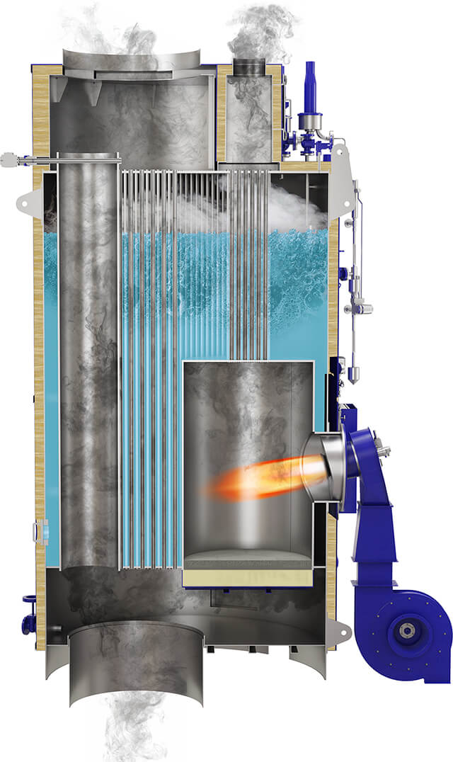
- Burner or heat-source faults reduce heat output and cause flame, temperature or pressure alarms
- Feedwater, circulation or level-control faults cause unstable operation and protective trips
- Soot, scale or internal deposits reduce heat transfer and cause poor output or abnormal temperatures
- Tube, coil, gasket or valve leakage causes visible water, steam, oil or fuel leakage and pressure loss
- Control, fan, flame-monitoring or safety-device faults cause repeated trips or failure of the normal operating sequence
- Compact footprint suitable for vessels with limited engine room space
- Dual‑fuel capability allows operation on either oil or gas, enhancing fuel flexibility
- Integrated EGE section with automated soot blower improves heat recovery and reduces emissions
- Fast start‑up and high part‑load efficiency compared to single‑fuel boilers
- Standard IMO D‑2 construction meets stringent marine safety requirements
- More complex control system than single‑fuel units, requiring specialised operator training
- EGE soot‑blowing mechanism adds maintenance tasks and can be a source of soot fires if not managed correctly
- Water level gauge glass is known to be fragile and may need frequent replacement
- Safety valve lifting incidents reported under rapid load changes
- Higher initial capital cost relative to basic oil‑only boilers
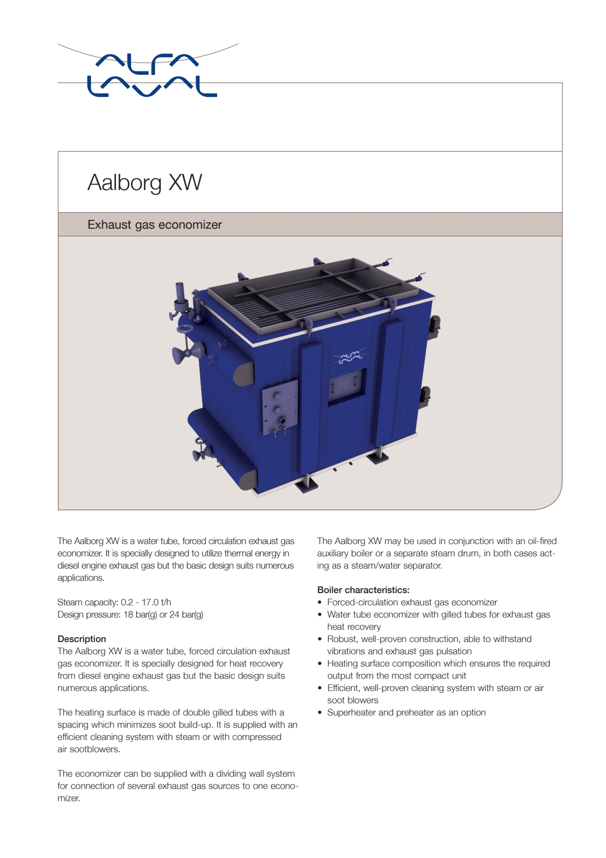
- Burner or heat-source faults reduce heat output and cause flame, temperature or pressure alarms
- Feedwater, circulation or level-control faults cause unstable operation and protective trips
- Soot, scale or internal deposits reduce heat transfer and cause poor output or abnormal temperatures
- Tube, coil, gasket or valve leakage causes visible water, steam, oil or fuel leakage and pressure loss
- Control, fan, flame-monitoring or safety-device faults cause repeated trips or failure of the normal operating sequence
- Rapid start‑up thanks to low water content
- Small footprint – ideal for vessels with limited engine‑room space
- High thermal efficiency from optimized heat‑transfer design
- Modular construction simplifies installation and routine maintenance
- Robust marine‑grade materials suitable for harsh sea environments
- Tube leakage at the tube plate is a known failure mode, requiring careful inspection and periodic retube
- Feed‑water control valve can stick if water treatment and level control are not rigorously maintained
- Soot accumulation on fire tubes demands regular cleaning to retain efficiency
- Steam output is limited compared with larger fire‑tube or multi‑drum boilers
- Composite design may be more sensitive to corrosion if water chemistry is not tightly controlled
Kangrim
1- Burner or heat-source faults reduce heat output and cause flame, temperature or pressure alarms
- Feedwater, circulation or level-control faults cause unstable operation and protective trips
- Soot, scale or internal deposits reduce heat transfer and cause poor output or abnormal temperatures
- Tube, coil, gasket or valve leakage causes visible water, steam, oil or fuel leakage and pressure loss
- Control, fan, flame-monitoring or safety-device faults cause repeated trips or failure of the normal operating sequence
- Dual‑fuel capability (oil + exhaust gas) improves fuel flexibility and reduces bunker consumption.
- Higher thermal efficiency by recovering waste heat from engine exhaust gases.
- Compact footprint compared with separate oil‑only and waste‑heat boilers, saving space on board.
- Designed for easy integration with existing marine propulsion systems and steam distribution networks.
- Complex control system requires skilled operators and more rigorous maintenance routines.
- Potential soot fire risk in the exhaust‑gas section if soot management protocols are not strictly followed.
- Oil burner ignition failures can occur if fuel quality or pre‑heat systems are inadequate.
- Corrosion of water‑side tubes and scale buildup demand regular chemical cleaning and inspection.