OceanSphere
Engines

AIS Transponder

medium 144 models total

An AIS transponder broadcasts the ship's own identity, position and course over VHF so other vessels and shore stations can see it directly, which makes it fundamentally different from radar, which only sees what it illuminates and reflects back.

Read more — AIS Transponder explained

What sets AIS apart from other navigation equipment

Radar and ECDIS build a picture of the world around the ship from reflected energy or stored charts. AIS works the other way: the transponder transmits the vessel's own identity, position, course, speed and voyage data over VHF at regular intervals, and receives the same broadcasts from every other AIS-fitted vessel and shore station within range. It is a cooperative system -- it depends on other ships transmitting honestly and correctly -- which is why it supplements rather than replaces radar and visual lookout, not the other way round.
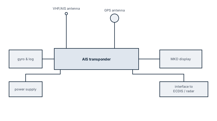
AIS transponder installation
Block diagram of an AIS transponder linked to its VHF/AIS antenna and GPS antenna, a gyro and log input for heading and speed, ship power, a minimum keyboard display and a data interface to ECDIS and radar.

Main components

Transceiver unit

Transmits and receives on two dedicated VHF channels simultaneously, using Self-Organising Time Division Multiple Access to share the channel with every other AIS unit in range without collisions.

GNSS position input

A dedicated internal or external GPS receiver providing the position and time reference the transponder broadcasts; loss of this input degrades the AIS message quality even if transmission continues.

Pilot plug and display

A standard connector giving a visiting pilot direct access to AIS data on a laptop, and a minimum keyboard and display unit on the bridge for entering voyage-specific data such as destination and ETA.

Selection criteria

  • Class A versus Class B: SOLAS vessels require Class A with its higher transmit power and reporting rate; Class B suits smaller craft not subject to SOLAS carriage requirements.
  • Integration with ECDIS and VDR, since AIS targets are normally overlaid on the electronic chart and its messages are logged by the voyage data recorder.
  • Antenna separation from other VHF and radar equipment to avoid mutual interference, a common installation oversight on retrofits.

Regulations and class

SOLAS Chapter V requires AIS on all ships of 300 gross tonnage and above on international voyages, cargo ships of 500 gross tonnage and above not on international voyages, and all passenger ships regardless of size. The transponder must transmit continuously except where the master judges it a security risk to do so, a provision intended for high-risk piracy areas rather than routine discretion. Class surveys check the unit's static data programming matches the vessel's actual particulars and that voyage data is updated each passage.

Typical faults

  • Incorrect or stale static data such as destination, draught or ship type, which the crew forgot to update and which then misleads other traffic and VTS.
  • GNSS antenna fault degrading position accuracy silently, since the transponder keeps transmitting even when its own position input has drifted.
  • VHF antenna or cable degradation reducing transmit range, often only discovered when a nearby vessel or VTS reports poor reception.
  • Overlapping MMSI numbers from a duplicated or incorrectly programmed identity, which corrupts the target picture for everyone tracking the vessel.

What to look for in a supplier

  • Type approval matching flag state requirements and confirmed interoperability with the vessel's existing ECDIS and VDR interfaces.
  • Straightforward static and voyage data entry at the bridge unit, since this is updated by the crew every passage and a clumsy interface leads to skipped updates.
  • Documented antenna separation guidance to avoid interference with existing VHF and radar installations during retrofit.

Check the static data programmed into the transponder against the vessel's actual particulars at every port call, not just at commissioning -- a wrong ship type or an outdated draught quietly undermines the whole reason AIS exists.

16 manufacturers · 144 models

Furuno

25
FA-100 unverified
Class
A
IMO Compliant
ja
Common Failures & Inspection Points
  • GNSS, heading or speed-input failure causes invalid or missing dynamic data and produces sensor alarms or incorrect transmitted information
  • VHF antenna or feeder faults reduce transmit and receive range and may cause built-in-test warnings
  • Incorrect static or voyage-data entry results in wrong vessel information being transmitted despite otherwise normal operation
  • Power-supply or network faults cause unit restart, blank display or loss of targets on connected bridge systems
  • Internal transceiver or GPS timing faults cause transmission alarms, missing own-ship reports or inability to receive nearby targets
Service: Verify own-ship static and voyage data, sensor inputs, antenna condition, alarms and target reception. Compare transmitted information with approved vessel particulars and bridge sensors. Check interfaces to ECDIS, radar or pilot plugs where fitted. Radio performance testing and configuration changes must follow approved service procedures.
Spare Parts: Carry fuses, approved power-supply parts, antenna connectors, interface cables and selected display or control components as supported by the manufacturer; maintain current configuration and vessel-data records.
Use Cases: Merchant vessels, passenger ships, offshore units and other craft required or equipped to exchange AIS traffic information.
FA-150 Mk2 unverified
Class
A
IMO Compliant
ja
Common Failures & Inspection Points
  • Loss of supply power from a tripped breaker, failed power unit, loose connection, or depleted reserve battery causes a dead unit, rebooting, or failure to transmit
  • Antenna, feeder, connector, or matching fault caused by corrosion, water ingress, or physical damage results in poor range, failed transmission, or weak received signals
  • Control-panel, display, keypad, or software faults can prevent channel selection, message handling, or normal operator input
  • Interface or position-data failure caused by wiring, configuration, or sensor faults can remove position information or connected-system data
  • Internal transmitter, receiver, or modem faults caused by component ageing or overheating can produce intermittent communication, alarms, or inability to establish a link
Service: Verify primary and reserve power, antenna and feeder condition, distress and safety functions permitted for routine testing, interfaces, audio quality, time and position inputs, and logged self-test results. Any regulatory test or adjustment must follow the vessel's radio procedures and manufacturer documentation.
Spare Parts: Carry the model-specific fuses, approved power-supply items, handset or microphone accessories, connector and sealing items, and critical interface or antenna components recommended by the manufacturer and vessel radio-maintenance plan.
Use Cases: Used on SOLAS merchant ships, offshore vessels, passenger ships, fishing vessels, workboats, and other craft requiring marine radio, distress, safety, or navigation communications.
SSAS-500 unverified
Type
SSAS
IMO Compliant
ja
Isps code
ja
Common Failures & Inspection Points
  • Loss of supply power from a tripped breaker, failed power unit, loose connection, or depleted reserve battery causes a dead unit, rebooting, or failure to transmit
  • Antenna, feeder, connector, or matching fault caused by corrosion, water ingress, or physical damage results in poor range, failed transmission, or weak received signals
  • Control-panel, display, keypad, or software faults can prevent channel selection, message handling, or normal operator input
  • Interface or position-data failure caused by wiring, configuration, or sensor faults can remove position information or connected-system data
  • Internal transmitter, receiver, or modem faults caused by component ageing or overheating can produce intermittent communication, alarms, or inability to establish a link
Service: Verify primary and reserve power, antenna and feeder condition, distress and safety functions permitted for routine testing, interfaces, audio quality, time and position inputs, and logged self-test results. Any regulatory test or adjustment must follow the vessel's radio procedures and manufacturer documentation.
Spare Parts: Carry the model-specific fuses, approved power-supply items, handset or microphone accessories, connector and sealing items, and critical interface or antenna components recommended by the manufacturer and vessel radio-maintenance plan.
Use Cases: Used on SOLAS merchant ships, offshore vessels, passenger ships, fishing vessels, workboats, and other craft requiring marine radio, distress, safety, or navigation communications.
SSAS-510 unverified
Type
SSAS
IMO Compliant
ja
Isps code
ja
Common Failures & Inspection Points
  • Loss of supply power from a tripped breaker, failed power unit, loose connection, or depleted reserve battery causes a dead unit, rebooting, or failure to transmit
  • Antenna, feeder, connector, or matching fault caused by corrosion, water ingress, or physical damage results in poor range, failed transmission, or weak received signals
  • Control-panel, display, keypad, or software faults can prevent channel selection, message handling, or normal operator input
  • Interface or position-data failure caused by wiring, configuration, or sensor faults can remove position information or connected-system data
  • Internal transmitter, receiver, or modem faults caused by component ageing or overheating can produce intermittent communication, alarms, or inability to establish a link
Service: Verify primary and reserve power, antenna and feeder condition, distress and safety functions permitted for routine testing, interfaces, audio quality, time and position inputs, and logged self-test results. Any regulatory test or adjustment must follow the vessel's radio procedures and manufacturer documentation.
Spare Parts: Carry the model-specific fuses, approved power-supply items, handset or microphone accessories, connector and sealing items, and critical interface or antenna components recommended by the manufacturer and vessel radio-maintenance plan.
Use Cases: Used on SOLAS merchant ships, offshore vessels, passenger ships, fishing vessels, workboats, and other craft requiring marine radio, distress, safety, or navigation communications.
LRIT-500 unverified
Type
LRIT
IMO Compliant
ja
Common Failures & Inspection Points
  • Loss of supply power from a tripped breaker, failed power unit, loose connection, or depleted reserve battery causes a dead unit, rebooting, or failure to transmit
  • Antenna, feeder, connector, or matching fault caused by corrosion, water ingress, or physical damage results in poor range, failed transmission, or weak received signals
  • Control-panel, display, keypad, or software faults can prevent channel selection, message handling, or normal operator input
  • Interface or position-data failure caused by wiring, configuration, or sensor faults can remove position information or connected-system data
  • Internal transmitter, receiver, or modem faults caused by component ageing or overheating can produce intermittent communication, alarms, or inability to establish a link
Service: Verify primary and reserve power, antenna and feeder condition, distress and safety functions permitted for routine testing, interfaces, audio quality, time and position inputs, and logged self-test results. Any regulatory test or adjustment must follow the vessel's radio procedures and manufacturer documentation.
Spare Parts: Carry the model-specific fuses, approved power-supply items, handset or microphone accessories, connector and sealing items, and critical interface or antenna components recommended by the manufacturer and vessel radio-maintenance plan.
Use Cases: Used on SOLAS merchant ships, offshore vessels, passenger ships, fishing vessels, workboats, and other craft requiring marine radio, distress, safety, or navigation communications.
FA-170 Mk2 unverified
IMO Compliant
ja
Common Failures & Inspection Points
  • GNSS, heading or speed-input failure causes invalid or missing dynamic data and produces sensor alarms or incorrect transmitted information
  • VHF antenna or feeder faults reduce transmit and receive range and may cause built-in-test warnings
  • Incorrect static or voyage-data entry results in wrong vessel information being transmitted despite otherwise normal operation
  • Power-supply or network faults cause unit restart, blank display or loss of targets on connected bridge systems
  • Internal transceiver or GPS timing faults cause transmission alarms, missing own-ship reports or inability to receive nearby targets
Service: Verify own-ship static and voyage data, sensor inputs, antenna condition, alarms and target reception. Compare transmitted information with approved vessel particulars and bridge sensors. Check interfaces to ECDIS, radar or pilot plugs where fitted. Radio performance testing and configuration changes must follow approved service procedures.
Spare Parts: Carry fuses, approved power-supply parts, antenna connectors, interface cables and selected display or control components as supported by the manufacturer; maintain current configuration and vessel-data records.
Use Cases: Merchant vessels, passenger ships, offshore units and other craft required or equipped to exchange AIS traffic information.
FA-150 Mk3 unverified
IMO Compliant
ja
Common Failures & Inspection Points
  • GNSS, heading or speed-input failure causes invalid or missing dynamic data and produces sensor alarms or incorrect transmitted information
  • VHF antenna or feeder faults reduce transmit and receive range and may cause built-in-test warnings
  • Incorrect static or voyage-data entry results in wrong vessel information being transmitted despite otherwise normal operation
  • Power-supply or network faults cause unit restart, blank display or loss of targets on connected bridge systems
  • Internal transceiver or GPS timing faults cause transmission alarms, missing own-ship reports or inability to receive nearby targets
Service: Verify own-ship static and voyage data, sensor inputs, antenna condition, alarms and target reception. Compare transmitted information with approved vessel particulars and bridge sensors. Check interfaces to ECDIS, radar or pilot plugs where fitted. Radio performance testing and configuration changes must follow approved service procedures.
Spare Parts: Carry fuses, approved power-supply parts, antenna connectors, interface cables and selected display or control components as supported by the manufacturer; maintain current configuration and vessel-data records.
Use Cases: Merchant vessels, passenger ships, offshore units and other craft required or equipped to exchange AIS traffic information.
FA-1710 AIS unverified
IMO Compliant
ja
Common Failures & Inspection Points
  • GNSS, heading or speed-input failure causes invalid or missing dynamic data and produces sensor alarms or incorrect transmitted information
  • VHF antenna or feeder faults reduce transmit and receive range and may cause built-in-test warnings
  • Incorrect static or voyage-data entry results in wrong vessel information being transmitted despite otherwise normal operation
  • Power-supply or network faults cause unit restart, blank display or loss of targets on connected bridge systems
  • Internal transceiver or GPS timing faults cause transmission alarms, missing own-ship reports or inability to receive nearby targets
Service: Verify own-ship static and voyage data, sensor inputs, antenna condition, alarms and target reception. Compare transmitted information with approved vessel particulars and bridge sensors. Check interfaces to ECDIS, radar or pilot plugs where fitted. Radio performance testing and configuration changes must follow approved service procedures.
Spare Parts: Carry fuses, approved power-supply parts, antenna connectors, interface cables and selected display or control components as supported by the manufacturer; maintain current configuration and vessel-data records.
Use Cases: Merchant vessels, passenger ships, offshore units and other craft required or equipped to exchange AIS traffic information.
FA-30 AIS unverified
IMO Compliant
ja
Common Failures & Inspection Points
  • GNSS, heading or speed-input failure causes invalid or missing dynamic data and produces sensor alarms or incorrect transmitted information
  • VHF antenna or feeder faults reduce transmit and receive range and may cause built-in-test warnings
  • Incorrect static or voyage-data entry results in wrong vessel information being transmitted despite otherwise normal operation
  • Power-supply or network faults cause unit restart, blank display or loss of targets on connected bridge systems
  • Internal transceiver or GPS timing faults cause transmission alarms, missing own-ship reports or inability to receive nearby targets
Service: Verify own-ship static and voyage data, sensor inputs, antenna condition, alarms and target reception. Compare transmitted information with approved vessel particulars and bridge sensors. Check interfaces to ECDIS, radar or pilot plugs where fitted. Radio performance testing and configuration changes must follow approved service procedures.
Spare Parts: Carry fuses, approved power-supply parts, antenna connectors, interface cables and selected display or control components as supported by the manufacturer; maintain current configuration and vessel-data records.
Use Cases: Merchant vessels, passenger ships, offshore units and other craft required or equipped to exchange AIS traffic information.
FA-170 Mk3 unverified
Common Failures & Inspection Points
  • Loss of supply power from a tripped breaker, failed power unit, loose connection, or depleted reserve battery causes a dead unit, rebooting, or failure to transmit
  • Antenna, feeder, connector, or matching fault caused by corrosion, water ingress, or physical damage results in poor range, failed transmission, or weak received signals
  • Control-panel, display, keypad, or software faults can prevent channel selection, message handling, or normal operator input
  • Interface or position-data failure caused by wiring, configuration, or sensor faults can remove position information or connected-system data
  • Internal transmitter, receiver, or modem faults caused by component ageing or overheating can produce intermittent communication, alarms, or inability to establish a link
Service: Verify primary and reserve power, antenna and feeder condition, distress and safety functions permitted for routine testing, interfaces, audio quality, time and position inputs, and logged self-test results. Any regulatory test or adjustment must follow the vessel's radio procedures and manufacturer documentation.
Spare Parts: Carry the model-specific fuses, approved power-supply items, handset or microphone accessories, connector and sealing items, and critical interface or antenna components recommended by the manufacturer and vessel radio-maintenance plan.
Use Cases: Used on SOLAS merchant ships, offshore vessels, passenger ships, fishing vessels, workboats, and other craft requiring marine radio, distress, safety, or navigation communications.
FA-1710 Mk2 unverified
Common Failures & Inspection Points
  • Sensor or antenna degradation caused by contamination, damage, ageing or poor exposure can produce missing, unstable or implausible data
  • Connector, cable or network faults caused by vibration, corrosion or disturbed terminations can cause intermittent data loss or interface alarms
  • Power-supply or internal electronics failure caused by ageing, heat or poor ventilation can result in resets, blank indications or complete loss of function
  • Configuration or software errors after service or replacement can cause incorrect data, rejected inputs or loss of communication with other bridge equipment
  • Mechanical damage or water ingress at exposed components can lead to erratic readings, repeated alarms or loss of the affected channel
Service: Inspect exposed sensors or antennas, cable routes, connectors, power supplies, displays and network interfaces. Confirm that indicated or recorded data is plausible and that built-in tests and alarms operate. Compare configuration and test results with the vessel's approved records and manufacturer documentation.
Spare Parts: Keep maker-recommended fuses, connectors, sensor accessories, fans, interface or power modules and other approved line-replaceable items that match the installed configuration.
Use Cases: Commercial ships, passenger vessels, offshore vessels and workboats requiring bridge navigation, recording, environmental or traffic information.
FA-40 Class B unverified
Common Failures & Inspection Points
  • Sensor or antenna degradation caused by contamination, damage, ageing or poor exposure can produce missing, unstable or implausible data
  • Connector, cable or network faults caused by vibration, corrosion or disturbed terminations can cause intermittent data loss or interface alarms
  • Power-supply or internal electronics failure caused by ageing, heat or poor ventilation can result in resets, blank indications or complete loss of function
  • Configuration or software errors after service or replacement can cause incorrect data, rejected inputs or loss of communication with other bridge equipment
  • Mechanical damage or water ingress at exposed components can lead to erratic readings, repeated alarms or loss of the affected channel
Service: Inspect exposed sensors or antennas, cable routes, connectors, power supplies, displays and network interfaces. Confirm that indicated or recorded data is plausible and that built-in tests and alarms operate. Compare configuration and test results with the vessel's approved records and manufacturer documentation.
Spare Parts: Keep maker-recommended fuses, connectors, sensor accessories, fans, interface or power modules and other approved line-replaceable items that match the installed configuration.
Use Cases: Commercial ships, passenger vessels, offshore vessels and workboats requiring bridge navigation, recording, environmental or traffic information.
FA-50 Class B unverified
Common Failures & Inspection Points
  • Sensor or antenna degradation caused by contamination, damage, ageing or poor exposure can produce missing, unstable or implausible data
  • Connector, cable or network faults caused by vibration, corrosion or disturbed terminations can cause intermittent data loss or interface alarms
  • Power-supply or internal electronics failure caused by ageing, heat or poor ventilation can result in resets, blank indications or complete loss of function
  • Configuration or software errors after service or replacement can cause incorrect data, rejected inputs or loss of communication with other bridge equipment
  • Mechanical damage or water ingress at exposed components can lead to erratic readings, repeated alarms or loss of the affected channel
Service: Inspect exposed sensors or antennas, cable routes, connectors, power supplies, displays and network interfaces. Confirm that indicated or recorded data is plausible and that built-in tests and alarms operate. Compare configuration and test results with the vessel's approved records and manufacturer documentation.
Spare Parts: Keep maker-recommended fuses, connectors, sensor accessories, fans, interface or power modules and other approved line-replaceable items that match the installed configuration.
Use Cases: Commercial ships, passenger vessels, offshore vessels and workboats requiring bridge navigation, recording, environmental or traffic information.
Furuno AIS Bridge Console-C unverified
Installation
Bridge Console
Common Failures & Inspection Points
  • Antenna, feeder or connector corrosion causes weak reception, poor transmission or high reflected-power indications
  • Power-supply or backup-battery faults cause resets or loss of availability during main-power failure
  • GNSS or data-interface loss causes missing position or identity information in transmitted messages
  • Microphone, handset, speaker or operator-control faults impair communication despite the main unit remaining powered
  • Configuration or programming errors can cause incorrect identity, channel or service behaviour
Service: Carry out the approved self-tests and operational checks without generating false distress alerts. Inspect antennas, feeders, connectors, earth or bonding arrangements where applicable, reserve supply and interfaces to navigation data. Verify programmed identity information and GMDSS records; exact radio tests, power measurements and configuration procedures must follow manufacturer and statutory documentation.
Spare Parts: Keep approved fuses, handset or microphone parts, antenna connectors, selected cables, printer consumables where fitted and critical power-supply or interface modules according to the vessel's GMDSS spares arrangement.
Use Cases: Used on seagoing vessels for distress, safety and routine maritime communications as part of the bridge and GMDSS installation.
Furuno AIS Mast-Head-C unverified
Installation
Mast-Head
Common Failures & Inspection Points
  • Loss of supply power from a tripped breaker, failed power unit, loose connection, or depleted reserve battery causes a dead unit, rebooting, or failure to transmit
  • Antenna, feeder, connector, or matching fault caused by corrosion, water ingress, or physical damage results in poor range, failed transmission, or weak received signals
  • Control-panel, display, keypad, or software faults can prevent channel selection, message handling, or normal operator input
  • Interface or position-data failure caused by wiring, configuration, or sensor faults can remove position information or connected-system data
  • Internal transmitter, receiver, or modem faults caused by component ageing or overheating can produce intermittent communication, alarms, or inability to establish a link
Service: Verify primary and reserve power, antenna and feeder condition, distress and safety functions permitted for routine testing, interfaces, audio quality, time and position inputs, and logged self-test results. Any regulatory test or adjustment must follow the vessel's radio procedures and manufacturer documentation.
Spare Parts: Carry the model-specific fuses, approved power-supply items, handset or microphone accessories, connector and sealing items, and critical interface or antenna components recommended by the manufacturer and vessel radio-maintenance plan.
Use Cases: Used on SOLAS merchant ships, offshore vessels, passenger ships, fishing vessels, workboats, and other craft requiring marine radio, distress, safety, or navigation communications.
Furuno AIS Standalone-C unverified
Installation
Standalone
Common Failures & Inspection Points
  • Antenna, feeder or tuning fault caused by corrosion, damaged cabling or poor connections, resulting in weak transmission, reception problems or equipment alarms
  • Power-supply or backup-battery failure caused by charger defects, aged batteries or wiring faults, resulting in loss of availability when main power is removed
  • Transmitter or receiver failure caused by RF-component or electronic faults, resulting in inability to establish communications or receive expected traffic
  • Position or time-input failure caused by GNSS or network faults, resulting in missing or incorrect data in distress or DSC functions
  • Control, display or software fault caused by hardware failure or configuration problems, resulting in frozen controls, error messages or unavailable functions
Service: Perform operational and self-tests permitted by the vessel's procedures without generating unintended distress alerts. Inspect antennas, feeders, grounding, power supplies, backup batteries and connected navigation-data inputs. Verify station identity, position input, time and configured communication services against approved records. Check printers, handsets, microphones and alarm interfaces where fitted. Maintain software, licenses and service subscriptions required by the installed system. Refer to manufacturer and regulatory documentation for exact test methods, battery criteria and approved servicing.
Spare Parts: Keep fuses, handset or microphone accessories, printer consumables where applicable, selected power-supply components and manufacturer-recommended electronic spares. Antenna or feeder repair materials and backup-battery arrangements should reflect the vessel's redundancy plan. Preserve type approval and programmed identity when replacing core units.
Use Cases: Distress, urgency, safety and routine maritime communications within the vessel's GMDSS and operational communications fit.
Furuno AIS Class A IMO-C unverified
Installation
Class A IMO
Common Failures & Inspection Points
  • Antenna, feeder or tuning fault caused by corrosion, damaged cabling or poor connections, resulting in weak transmission, reception problems or equipment alarms
  • Power-supply or backup-battery failure caused by charger defects, aged batteries or wiring faults, resulting in loss of availability when main power is removed
  • Transmitter or receiver failure caused by RF-component or electronic faults, resulting in inability to establish communications or receive expected traffic
  • Position or time-input failure caused by GNSS or network faults, resulting in missing or incorrect data in distress or DSC functions
  • Control, display or software fault caused by hardware failure or configuration problems, resulting in frozen controls, error messages or unavailable functions
Service: Perform operational and self-tests permitted by the vessel's procedures without generating unintended distress alerts. Inspect antennas, feeders, grounding, power supplies, backup batteries and connected navigation-data inputs. Verify station identity, position input, time and configured communication services against approved records. Check printers, handsets, microphones and alarm interfaces where fitted. Maintain software, licenses and service subscriptions required by the installed system. Refer to manufacturer and regulatory documentation for exact test methods, battery criteria and approved servicing.
Spare Parts: Keep fuses, handset or microphone accessories, printer consumables where applicable, selected power-supply components and manufacturer-recommended electronic spares. Antenna or feeder repair materials and backup-battery arrangements should reflect the vessel's redundancy plan. Preserve type approval and programmed identity when replacing core units.
Use Cases: Distress, urgency, safety and routine maritime communications within the vessel's GMDSS and operational communications fit.
Furuno AIS Class B CS-C unverified
Installation
Class B CS
Common Failures & Inspection Points
  • Antenna, feeder or tuning fault caused by corrosion, damaged cabling or poor connections, resulting in weak transmission, reception problems or equipment alarms
  • Power-supply or backup-battery failure caused by charger defects, aged batteries or wiring faults, resulting in loss of availability when main power is removed
  • Transmitter or receiver failure caused by RF-component or electronic faults, resulting in inability to establish communications or receive expected traffic
  • Position or time-input failure caused by GNSS or network faults, resulting in missing or incorrect data in distress or DSC functions
  • Control, display or software fault caused by hardware failure or configuration problems, resulting in frozen controls, error messages or unavailable functions
Service: Perform operational and self-tests permitted by the vessel's procedures without generating unintended distress alerts. Inspect antennas, feeders, grounding, power supplies, backup batteries and connected navigation-data inputs. Verify station identity, position input, time and configured communication services against approved records. Check printers, handsets, microphones and alarm interfaces where fitted. Maintain software, licenses and service subscriptions required by the installed system. Refer to manufacturer and regulatory documentation for exact test methods, battery criteria and approved servicing.
Spare Parts: Keep fuses, handset or microphone accessories, printer consumables where applicable, selected power-supply components and manufacturer-recommended electronic spares. Antenna or feeder repair materials and backup-battery arrangements should reflect the vessel's redundancy plan. Preserve type approval and programmed identity when replacing core units.
Use Cases: Distress, urgency, safety and routine maritime communications within the vessel's GMDSS and operational communications fit.
Furuno AIS Class B SOTDMA-C unverified
Installation
Class B SOTDMA
Common Failures & Inspection Points
  • Antenna, feeder or connector corrosion causes weak reception, poor transmission or high reflected-power indications
  • Power-supply or backup-battery faults cause resets or loss of availability during main-power failure
  • GNSS or data-interface loss causes missing position or identity information in transmitted messages
  • Microphone, handset, speaker or operator-control faults impair communication despite the main unit remaining powered
  • Configuration or programming errors can cause incorrect identity, channel or service behaviour
Service: Carry out the approved self-tests and operational checks without generating false distress alerts. Inspect antennas, feeders, connectors, earth or bonding arrangements where applicable, reserve supply and interfaces to navigation data. Verify programmed identity information and GMDSS records; exact radio tests, power measurements and configuration procedures must follow manufacturer and statutory documentation.
Spare Parts: Keep approved fuses, handset or microphone parts, antenna connectors, selected cables, printer consumables where fitted and critical power-supply or interface modules according to the vessel's GMDSS spares arrangement.
Use Cases: Used on seagoing vessels for distress, safety and routine maritime communications as part of the bridge and GMDSS installation.
Furuno Long Range ID-C unverified
Feature
Long Range ID
Common Failures & Inspection Points
  • GNSS, heading or speed-input failure causes invalid dynamic data and sensor alarms
  • VHF antenna or feeder faults reduce transmit and receive range and may trigger built-in-test warnings
  • Incorrect static or voyage data results in wrong vessel information being transmitted
  • Power-supply or network faults cause unit resets, blank displays or loss of target data to bridge systems
  • Internal transceiver or timing faults cause transmission alarms or missing nearby targets
Service: Verify own-ship static and voyage data, sensor inputs, antenna condition, alarms and target reception. Compare transmitted information with approved vessel particulars. Check interfaces to ECDIS, radar and pilot connections where fitted. Refer to the manufacturer documentation for the exact figure for radio-performance and service criteria.
Spare Parts: Carry fuses, power-supply parts, antenna connectors, interface cables and manufacturer-supported display or control modules where justified.
Use Cases: Traffic awareness, collision-avoidance support and regulatory vessel identification.
Furuno Inland AIS-C unverified
Feature
Inland AIS
Common Failures & Inspection Points
  • Sensor, antenna or transducer fault, typically indicated by missing, unstable or implausible navigation data
  • Power-supply or processor failure, typically indicated by blank display, rebooting or unavailable function
  • Network/interface fault, typically indicated by missing data on connected bridge systems or communication alarms
  • Cable/connector corrosion or water ingress, typically indicated by intermittent operation or signal loss
  • Recording/storage or software fault on recorder-type equipment, typically indicated by data gaps, recording alarms or failed playback
Service: Check self-tests, sensor/transducer condition, data interfaces, time/position inputs, recording status where applicable, power supplies and alarm history; performance tests and calibration must follow approved manufacturer and statutory procedures.
Spare Parts: Carry critical fuses, power supplies, interface modules, storage media where approved, sensors/transducers or display peripherals according to equipment criticality.
Use Cases: Used on merchant, passenger, offshore and naval vessels for navigation, bridge situational awareness, environmental sensing and voyage-data recording. This entry applies specifically to the AIS Transponder variant identified as Furuno Furuno Inland AIS-C.
Furuno AIS Base Station-C unverified
Feature
AIS Base Station
Common Failures & Inspection Points
  • GNSS, VHF antenna or transceiver fault caused by damage, poor connections or electronics failure, resulting in missing targets, transmission alarms or invalid own-ship data
  • Power-supply failure caused by breaker, converter or wiring faults, resulting in loss of the equipment or repeated restarts
  • Network or interface failure caused by damaged cabling, port faults or configuration changes, resulting in loss of data to connected systems
  • Display, processor or control failure caused by hardware or software faults, resulting in frozen indications, alarms or unavailable functions
  • Incorrect configuration or time, position or sensor input caused by setup or upstream faults, resulting in misleading or incomplete information
Service: Inspect sensors, antennas, transducers, cameras, cabling, power supplies and network interfaces applicable to the installed equipment. Compare displayed information with independent references where possible and investigate recurring alarms or missing channels. Verify required outputs to other bridge systems and preserve configuration before approved software or hardware maintenance. Clean exposed sensors and optical surfaces without damaging coatings or seals. Check backup power or recording arrangements where applicable. Refer to the manufacturer documentation for the exact figure for test, calibration, update and recovery procedures.
Spare Parts: Keep fuses, selected power-supply and interface modules, cables or connectors, storage media where applicable and manufacturer-recommended sensor or electronic spares. Replacement core units must remain compatible with the approved bridge installation. Preserve configuration and recorded setup data.
Use Cases: Bridge navigation, monitoring, recording and maritime safety information functions on merchant ships, passenger vessels, offshore units and workboats.
Furuno AIS Receiver Only-C unverified
Feature
AIS Receiver Only
Common Failures & Inspection Points
  • GNSS, VHF antenna or transceiver fault caused by damage, poor connections or electronics failure, resulting in missing targets, transmission alarms or invalid own-ship data
  • Power-supply failure caused by breaker, converter or wiring faults, resulting in loss of the equipment or repeated restarts
  • Network or interface failure caused by damaged cabling, port faults or configuration changes, resulting in loss of data to connected systems
  • Display, processor or control failure caused by hardware or software faults, resulting in frozen indications, alarms or unavailable functions
  • Incorrect configuration or time, position or sensor input caused by setup or upstream faults, resulting in misleading or incomplete information
Service: Inspect sensors, antennas, transducers, cameras, cabling, power supplies and network interfaces applicable to the installed equipment. Compare displayed information with independent references where possible and investigate recurring alarms or missing channels. Verify required outputs to other bridge systems and preserve configuration before approved software or hardware maintenance. Clean exposed sensors and optical surfaces without damaging coatings or seals. Check backup power or recording arrangements where applicable. Refer to the manufacturer documentation for the exact figure for test, calibration, update and recovery procedures.
Spare Parts: Keep fuses, selected power-supply and interface modules, cables or connectors, storage media where applicable and manufacturer-recommended sensor or electronic spares. Replacement core units must remain compatible with the approved bridge installation. Preserve configuration and recorded setup data.
Use Cases: Bridge navigation, monitoring, recording and maritime safety information functions on merchant ships, passenger vessels, offshore units and workboats.
Furuno AIS Class A+-C unverified
Feature
AIS Class A+
Common Failures & Inspection Points
  • GNSS, heading or speed-input failure causes invalid dynamic data and sensor alarms
  • VHF antenna or feeder faults reduce transmit and receive range and may trigger built-in-test warnings
  • Incorrect static or voyage data results in wrong vessel information being transmitted
  • Power-supply or network faults cause unit resets, blank displays or loss of target data to bridge systems
  • Internal transceiver or timing faults cause transmission alarms or missing nearby targets
Service: Verify own-ship static and voyage data, sensor inputs, antenna condition, alarms and target reception. Compare transmitted information with approved vessel particulars. Check interfaces to ECDIS, radar and pilot connections where fitted. Refer to the manufacturer documentation for the exact figure for radio-performance and service criteria.
Spare Parts: Carry fuses, power-supply parts, antenna connectors, interface cables and manufacturer-supported display or control modules where justified.
Use Cases: Traffic awareness, collision-avoidance support and regulatory vessel identification.
Furuno AIS-SART Combo-C unverified
Feature
AIS-SART Combo
Common Failures & Inspection Points
  • GNSS, heading or speed-input failure causes invalid dynamic data and sensor alarms
  • VHF antenna or feeder faults reduce transmit and receive range and may trigger built-in-test warnings
  • Incorrect static or voyage data results in wrong vessel information being transmitted
  • Power-supply or network faults cause unit resets, blank displays or loss of target data to bridge systems
  • Internal transceiver or timing faults cause transmission alarms or missing nearby targets
Service: Verify own-ship static and voyage data, sensor inputs, antenna condition, alarms and target reception. Compare transmitted information with approved vessel particulars. Check interfaces to ECDIS, radar and pilot connections where fitted. Refer to the manufacturer documentation for the exact figure for radio-performance and service criteria.
Spare Parts: Carry fuses, power-supply parts, antenna connectors, interface cables and manufacturer-supported display or control modules where justified.
Use Cases: Traffic awareness, collision-avoidance support and regulatory vessel identification.

em-trak

21
EM-TRAK A200 unverified
Class
B
Common Failures & Inspection Points
  • GNSS, heading or speed-input failure causes invalid or missing dynamic data and produces sensor alarms or incorrect transmitted information
  • VHF antenna or feeder faults reduce transmit and receive range and may cause built-in-test warnings
  • Incorrect static or voyage-data entry results in wrong vessel information being transmitted despite otherwise normal operation
  • Power-supply or network faults cause unit restart, blank display or loss of targets on connected bridge systems
  • Internal transceiver or GPS timing faults cause transmission alarms, missing own-ship reports or inability to receive nearby targets
Service: Verify own-ship static and voyage data, sensor inputs, antenna condition, alarms and target reception. Compare transmitted information with approved vessel particulars and bridge sensors. Check interfaces to ECDIS, radar or pilot plugs where fitted. Radio performance testing and configuration changes must follow approved service procedures.
Spare Parts: Carry fuses, approved power-supply parts, antenna connectors, interface cables and selected display or control components as supported by the manufacturer; maintain current configuration and vessel-data records.
Use Cases: Merchant vessels, passenger ships, offshore units and other craft required or equipped to exchange AIS traffic information.
EM-TRAK A100 unverified
Class
B
Common Failures & Inspection Points
  • GNSS, heading or speed-input failure causes invalid or missing dynamic data and produces sensor alarms or incorrect transmitted information
  • VHF antenna or feeder faults reduce transmit and receive range and may cause built-in-test warnings
  • Incorrect static or voyage-data entry results in wrong vessel information being transmitted despite otherwise normal operation
  • Power-supply or network faults cause unit restart, blank display or loss of targets on connected bridge systems
  • Internal transceiver or GPS timing faults cause transmission alarms, missing own-ship reports or inability to receive nearby targets
Service: Verify own-ship static and voyage data, sensor inputs, antenna condition, alarms and target reception. Compare transmitted information with approved vessel particulars and bridge sensors. Check interfaces to ECDIS, radar or pilot plugs where fitted. Radio performance testing and configuration changes must follow approved service procedures.
Spare Parts: Carry fuses, approved power-supply parts, antenna connectors, interface cables and selected display or control components as supported by the manufacturer; maintain current configuration and vessel-data records.
Use Cases: Merchant vessels, passenger ships, offshore units and other craft required or equipped to exchange AIS traffic information.
EM-TRAK B954 unverified
Class
B
Common Failures & Inspection Points
  • GNSS, heading or speed-input failure causes invalid or missing dynamic data and produces sensor alarms or incorrect transmitted information
  • VHF antenna or feeder faults reduce transmit and receive range and may cause built-in-test warnings
  • Incorrect static or voyage-data entry results in wrong vessel information being transmitted despite otherwise normal operation
  • Power-supply or network faults cause unit restart, blank display or loss of targets on connected bridge systems
  • Internal transceiver or GPS timing faults cause transmission alarms, missing own-ship reports or inability to receive nearby targets
Service: Verify own-ship static and voyage data, sensor inputs, antenna condition, alarms and target reception. Compare transmitted information with approved vessel particulars and bridge sensors. Check interfaces to ECDIS, radar or pilot plugs where fitted. Radio performance testing and configuration changes must follow approved service procedures.
Spare Parts: Carry fuses, approved power-supply parts, antenna connectors, interface cables and selected display or control components as supported by the manufacturer; maintain current configuration and vessel-data records.
Use Cases: Merchant vessels, passenger ships, offshore units and other craft required or equipped to exchange AIS traffic information.
A200 Class A unverified
Class
A
Common Failures & Inspection Points
  • Sensor or antenna degradation caused by contamination, damage, ageing or poor exposure can produce missing, unstable or implausible data
  • Connector, cable or network faults caused by vibration, corrosion or disturbed terminations can cause intermittent data loss or interface alarms
  • Power-supply or internal electronics failure caused by ageing, heat or poor ventilation can result in resets, blank indications or complete loss of function
  • Configuration or software errors after service or replacement can cause incorrect data, rejected inputs or loss of communication with other bridge equipment
  • Mechanical damage or water ingress at exposed components can lead to erratic readings, repeated alarms or loss of the affected channel
Service: Inspect exposed sensors or antennas, cable routes, connectors, power supplies, displays and network interfaces. Confirm that indicated or recorded data is plausible and that built-in tests and alarms operate. Compare configuration and test results with the vessel's approved records and manufacturer documentation.
Spare Parts: Keep maker-recommended fuses, connectors, sensor accessories, fans, interface or power modules and other approved line-replaceable items that match the installed configuration.
Use Cases: Commercial ships, passenger vessels, offshore vessels and workboats requiring bridge navigation, recording, environmental or traffic information.
B954 Class B unverified
Class
B
Common Failures & Inspection Points
  • Sensor or antenna degradation caused by contamination, damage, ageing or poor exposure can produce missing, unstable or implausible data
  • Connector, cable or network faults caused by vibration, corrosion or disturbed terminations can cause intermittent data loss or interface alarms
  • Power-supply or internal electronics failure caused by ageing, heat or poor ventilation can result in resets, blank indications or complete loss of function
  • Configuration or software errors after service or replacement can cause incorrect data, rejected inputs or loss of communication with other bridge equipment
  • Mechanical damage or water ingress at exposed components can lead to erratic readings, repeated alarms or loss of the affected channel
Service: Inspect exposed sensors or antennas, cable routes, connectors, power supplies, displays and network interfaces. Confirm that indicated or recorded data is plausible and that built-in tests and alarms operate. Compare configuration and test results with the vessel's approved records and manufacturer documentation.
Spare Parts: Keep maker-recommended fuses, connectors, sensor accessories, fans, interface or power modules and other approved line-replaceable items that match the installed configuration.
Use Cases: Commercial ships, passenger vessels, offshore vessels and workboats requiring bridge navigation, recording, environmental or traffic information.
S300 AIS unverified
Class
B
Common Failures & Inspection Points
  • Loss of supply power from a tripped breaker, failed power unit, loose connection, or depleted reserve battery causes a dead unit, rebooting, or failure to transmit
  • Antenna, feeder, connector, or matching fault caused by corrosion, water ingress, or physical damage results in poor range, failed transmission, or weak received signals
  • Control-panel, display, keypad, or software faults can prevent channel selection, message handling, or normal operator input
  • Interface or position-data failure caused by wiring, configuration, or sensor faults can remove position information or connected-system data
  • Internal transmitter, receiver, or modem faults caused by component ageing or overheating can produce intermittent communication, alarms, or inability to establish a link
Service: Verify primary and reserve power, antenna and feeder condition, distress and safety functions permitted for routine testing, interfaces, audio quality, time and position inputs, and logged self-test results. Any regulatory test or adjustment must follow the vessel's radio procedures and manufacturer documentation.
Spare Parts: Carry the model-specific fuses, approved power-supply items, handset or microphone accessories, connector and sealing items, and critical interface or antenna components recommended by the manufacturer and vessel radio-maintenance plan.
Use Cases: Used on SOLAS merchant ships, offshore vessels, passenger ships, fishing vessels, workboats, and other craft requiring marine radio, distress, safety, or navigation communications.
A200 Mk2 unverified
IMO Compliant
ja
Common Failures & Inspection Points
  • GNSS, heading or speed-input failure causes invalid or missing dynamic data and produces sensor alarms or incorrect transmitted information
  • VHF antenna or feeder faults reduce transmit and receive range and may cause built-in-test warnings
  • Incorrect static or voyage-data entry results in wrong vessel information being transmitted despite otherwise normal operation
  • Power-supply or network faults cause unit restart, blank display or loss of targets on connected bridge systems
  • Internal transceiver or GPS timing faults cause transmission alarms, missing own-ship reports or inability to receive nearby targets
Service: Verify own-ship static and voyage data, sensor inputs, antenna condition, alarms and target reception. Compare transmitted information with approved vessel particulars and bridge sensors. Check interfaces to ECDIS, radar or pilot plugs where fitted. Radio performance testing and configuration changes must follow approved service procedures.
Spare Parts: Carry fuses, approved power-supply parts, antenna connectors, interface cables and selected display or control components as supported by the manufacturer; maintain current configuration and vessel-data records.
Use Cases: Merchant vessels, passenger ships, offshore units and other craft required or equipped to exchange AIS traffic information.
em-trak B400
B400 unverified
IMO Compliant
ja
Common Failures & Inspection Points
  • GNSS, heading or speed-input failure causes invalid or missing dynamic data and produces sensor alarms or incorrect transmitted information
  • VHF antenna or feeder faults reduce transmit and receive range and may cause built-in-test warnings
  • Incorrect static or voyage-data entry results in wrong vessel information being transmitted despite otherwise normal operation
  • Power-supply or network faults cause unit restart, blank display or loss of targets on connected bridge systems
  • Internal transceiver or GPS timing faults cause transmission alarms, missing own-ship reports or inability to receive nearby targets
Service: Verify own-ship static and voyage data, sensor inputs, antenna condition, alarms and target reception. Compare transmitted information with approved vessel particulars and bridge sensors. Check interfaces to ECDIS, radar or pilot plugs where fitted. Radio performance testing and configuration changes must follow approved service procedures.
Spare Parts: Carry fuses, approved power-supply parts, antenna connectors, interface cables and selected display or control components as supported by the manufacturer; maintain current configuration and vessel-data records.
Use Cases: Merchant vessels, passenger ships, offshore units and other craft required or equipped to exchange AIS traffic information.
S300 AIS Mk2 unverified
IMO Compliant
ja
Common Failures & Inspection Points
  • GNSS, heading or speed-input failure causes invalid or missing dynamic data and produces sensor alarms or incorrect transmitted information
  • VHF antenna or feeder faults reduce transmit and receive range and may cause built-in-test warnings
  • Incorrect static or voyage-data entry results in wrong vessel information being transmitted despite otherwise normal operation
  • Power-supply or network faults cause unit restart, blank display or loss of targets on connected bridge systems
  • Internal transceiver or GPS timing faults cause transmission alarms, missing own-ship reports or inability to receive nearby targets
Service: Verify own-ship static and voyage data, sensor inputs, antenna condition, alarms and target reception. Compare transmitted information with approved vessel particulars and bridge sensors. Check interfaces to ECDIS, radar or pilot plugs where fitted. Radio performance testing and configuration changes must follow approved service procedures.
Spare Parts: Carry fuses, approved power-supply parts, antenna connectors, interface cables and selected display or control components as supported by the manufacturer; maintain current configuration and vessel-data records.
Use Cases: Merchant vessels, passenger ships, offshore units and other craft required or equipped to exchange AIS traffic information.
em-trak AIS Bridge Console-C unverified
Installation
Bridge Console
Common Failures & Inspection Points
  • Antenna, feeder or tuning fault caused by corrosion, damaged cabling or poor connections, resulting in weak transmission, reception problems or equipment alarms
  • Power-supply or backup-battery failure caused by charger defects, aged batteries or wiring faults, resulting in loss of availability when normal power is removed
  • Transmitter or receiver failure caused by RF-component or electronic faults, resulting in inability to establish communications or receive expected traffic
  • Position, time or identity-input problem caused by navigation-data or configuration faults, resulting in missing or incorrect information in distress or DSC functions
  • Control, display or software fault caused by hardware failure or configuration problems, resulting in frozen controls, error messages or unavailable functions
Service: Perform operational and self-tests permitted by the vessel's procedures without generating unintended distress alerts. Inspect antennas, feeders, grounding, power supplies, backup batteries and connected navigation-data inputs. Verify programmed station identity, position input, time and configured communication services against approved records. Check handsets, microphones, printers and alarm interfaces where fitted. Maintain software, licenses and service subscriptions required by the installed system. Refer to manufacturer and regulatory documentation for exact test methods, battery criteria and approved servicing.
Spare Parts: Keep fuses, handset or microphone accessories, printer consumables where applicable, selected power-supply components and manufacturer-recommended electronic spares. Antenna or feeder repair materials and backup-battery arrangements should reflect the vessel's redundancy plan. Preserve type approval and programmed identity when replacing core units.
Use Cases: Distress, urgency, safety and routine maritime communications within the vessel's GMDSS and operational communications fit.
em-trak AIS Mast-Head-C unverified
Installation
Mast-Head
Common Failures & Inspection Points
  • Antenna, feeder or tuning fault caused by corrosion, damaged cabling or poor connections, resulting in weak transmission, reception problems or equipment alarms
  • Power-supply or backup-battery failure caused by charger defects, aged batteries or wiring faults, resulting in loss of availability when main power is removed
  • Transmitter or receiver failure caused by RF-component or electronic faults, resulting in inability to establish communications or receive expected traffic
  • Position or time-input failure caused by GNSS or network faults, resulting in missing or incorrect data in distress or DSC functions
  • Control, display or software fault caused by hardware failure or configuration problems, resulting in frozen controls, error messages or unavailable functions
Service: Perform operational and self-tests permitted by the vessel's procedures without generating unintended distress alerts. Inspect antennas, feeders, grounding, power supplies, backup batteries and connected navigation-data inputs. Verify station identity, position input, time and configured communication services against approved records. Check printers, handsets, microphones and alarm interfaces where fitted. Maintain software, licenses and service subscriptions required by the installed system. Refer to manufacturer and regulatory documentation for exact test methods, battery criteria and approved servicing.
Spare Parts: Keep fuses, handset or microphone accessories, printer consumables where applicable, selected power-supply components and manufacturer-recommended electronic spares. Antenna or feeder repair materials and backup-battery arrangements should reflect the vessel's redundancy plan. Preserve type approval and programmed identity when replacing core units.
Use Cases: Distress, urgency, safety and routine maritime communications within the vessel's GMDSS and operational communications fit.
em-trak AIS Standalone-C unverified
Installation
Standalone
Common Failures & Inspection Points
  • GNSS, heading or speed-input failure causes invalid dynamic data and sensor alarms
  • VHF antenna or feeder faults reduce transmit and receive range and may trigger built-in-test warnings
  • Incorrect static or voyage data results in wrong vessel information being transmitted
  • Power-supply or network faults cause unit resets, blank displays or loss of target data to bridge systems
  • Internal transceiver or timing faults cause transmission alarms or missing nearby targets
Service: Verify own-ship static and voyage data, sensor inputs, antenna condition, alarms and target reception. Compare transmitted information with approved vessel particulars. Check interfaces to ECDIS, radar and pilot connections where fitted. Radio-performance testing should follow approved service procedures.
Spare Parts: Carry fuses, power-supply parts, antenna connectors, interface cables and manufacturer-supported display or control modules where justified.
Use Cases: Traffic awareness, collision avoidance support and regulatory reporting on merchant and passenger vessels.
em-trak AIS Class A IMO-C unverified
Installation
Class A IMO
Common Failures & Inspection Points
  • GNSS, heading or speed-input failure causes invalid dynamic data and sensor alarms
  • VHF antenna or feeder faults reduce transmit and receive range and may trigger built-in-test warnings
  • Incorrect static or voyage data results in wrong vessel information being transmitted
  • Power-supply or network faults cause unit resets, blank displays or loss of target data to bridge systems
  • Internal transceiver or timing faults cause transmission alarms or missing nearby targets
Service: Verify own-ship static and voyage data, sensor inputs, antenna condition, alarms and target reception. Compare transmitted information with approved vessel particulars. Check interfaces to ECDIS, radar and pilot connections where fitted. Radio-performance testing should follow approved service procedures.
Spare Parts: Carry fuses, power-supply parts, antenna connectors, interface cables and manufacturer-supported display or control modules where justified.
Use Cases: Traffic awareness, collision avoidance support and regulatory reporting on merchant and passenger vessels.
em-trak AIS Class B CS-C unverified
Installation
Class B CS
Common Failures & Inspection Points
  • GNSS, heading or speed-input failure causes invalid dynamic data and sensor alarms
  • VHF antenna or feeder faults reduce transmit and receive range and may trigger built-in-test warnings
  • Incorrect static or voyage data results in wrong vessel information being transmitted
  • Power-supply or network faults cause unit resets, blank displays or loss of target data to bridge systems
  • Internal transceiver or timing faults cause transmission alarms or missing nearby targets
Service: Verify own-ship static and voyage data, sensor inputs, antenna condition, alarms and target reception. Compare transmitted information with approved vessel particulars. Check interfaces to ECDIS, radar and pilot connections where fitted. Radio-performance testing should follow approved service procedures.
Spare Parts: Carry fuses, power-supply parts, antenna connectors, interface cables and manufacturer-supported display or control modules where justified.
Use Cases: Traffic awareness, collision avoidance support and regulatory reporting on merchant and passenger vessels.
em-trak AIS Class B SOTDMA-C unverified
Installation
Class B SOTDMA
Common Failures & Inspection Points
  • Antenna, feeder or tuning fault caused by corrosion, damaged cabling or poor connections, resulting in weak transmission, reception problems or equipment alarms
  • Power-supply or backup-battery failure caused by charger defects, aged batteries or wiring faults, resulting in loss of availability when normal power is removed
  • Transmitter or receiver failure caused by RF-component or electronic faults, resulting in inability to establish communications or receive expected traffic
  • Position, time or identity-input problem caused by navigation-data or configuration faults, resulting in missing or incorrect information in distress or DSC functions
  • Control, display or software fault caused by hardware failure or configuration problems, resulting in frozen controls, error messages or unavailable functions
Service: Perform operational and self-tests permitted by the vessel's procedures without generating unintended distress alerts. Inspect antennas, feeders, grounding, power supplies, backup batteries and connected navigation-data inputs. Verify programmed station identity, position input, time and configured communication services against approved records. Check handsets, microphones, printers and alarm interfaces where fitted. Maintain software, licenses and service subscriptions required by the installed system. Refer to manufacturer and regulatory documentation for exact test methods, battery criteria and approved servicing.
Spare Parts: Keep fuses, handset or microphone accessories, printer consumables where applicable, selected power-supply components and manufacturer-recommended electronic spares. Antenna or feeder repair materials and backup-battery arrangements should reflect the vessel's redundancy plan. Preserve type approval and programmed identity when replacing core units.
Use Cases: Distress, urgency, safety and routine maritime communications within the vessel's GMDSS and operational communications fit.
em-trak Long Range ID-C unverified
Feature
Long Range ID
Common Failures & Inspection Points
  • GNSS, VHF antenna or transceiver fault caused by damage, poor connections or electronics failure, resulting in missing targets, transmission alarms or invalid own-ship data
  • Power-supply failure caused by breaker, converter or wiring faults, resulting in loss of the equipment or repeated restarts
  • Network or interface failure caused by damaged cabling, port faults or configuration changes, resulting in loss of data to connected systems
  • Display, processor or control failure caused by hardware or software faults, resulting in frozen indications, alarms or unavailable functions
  • Incorrect configuration or time, position or sensor input caused by setup or upstream faults, resulting in misleading or incomplete information
Service: Inspect sensors, antennas, transducers, cameras, cabling, power supplies and network interfaces applicable to the installed equipment. Compare displayed information with independent references where possible and investigate recurring alarms or missing channels. Verify required outputs to other bridge systems and preserve configuration before approved software or hardware maintenance. Clean exposed sensors and optical surfaces without damaging coatings or seals. Check backup power or recording arrangements where applicable. Refer to the manufacturer documentation for the exact figure for test, calibration, update and recovery procedures.
Spare Parts: Keep fuses, selected power-supply and interface modules, cables or connectors, storage media where applicable and manufacturer-recommended sensor or electronic spares. Replacement core units must remain compatible with the approved bridge installation. Preserve configuration and recorded setup data.
Use Cases: Bridge navigation, monitoring, recording and maritime safety information functions on merchant ships, passenger vessels, offshore units and workboats.
em-trak Inland AIS-C unverified
Feature
Inland AIS
Common Failures & Inspection Points
  • GNSS, heading or speed-input failure causes invalid dynamic data and sensor alarms
  • VHF antenna or feeder faults reduce transmit and receive range and may trigger built-in-test warnings
  • Incorrect static or voyage data results in wrong vessel information being transmitted
  • Power-supply or network faults cause unit resets, blank displays or loss of target data to bridge systems
  • Internal transceiver or timing faults cause transmission alarms or missing nearby targets
Service: Verify own-ship static and voyage data, sensor inputs, antenna condition, alarms and target reception. Compare transmitted information with approved vessel particulars. Check interfaces to ECDIS, radar and pilot connections where fitted. Refer to the manufacturer documentation for the exact figure for radio-performance and service criteria.
Spare Parts: Carry fuses, power-supply parts, antenna connectors, interface cables and manufacturer-supported display or control modules where justified.
Use Cases: Traffic awareness, collision-avoidance support and regulatory vessel identification.
em-trak AIS Base Station-C unverified
Feature
AIS Base Station
Common Failures & Inspection Points
  • GNSS, VHF antenna or transceiver fault caused by damage, poor connections or electronics failure, resulting in missing targets, transmission alarms or invalid own-ship data
  • Power-supply failure caused by breaker, converter or wiring faults, resulting in loss of the equipment or repeated restarts
  • Network or interface failure caused by damaged cabling, port faults or configuration changes, resulting in loss of data to connected systems
  • Display, processor or control failure caused by hardware or software faults, resulting in frozen indications, alarms or unavailable functions
  • Incorrect configuration or time, position or sensor input caused by setup or upstream faults, resulting in misleading or incomplete information
Service: Inspect sensors, antennas, transducers, cameras, cabling, power supplies and network interfaces applicable to the installed equipment. Compare displayed information with independent references where possible and investigate recurring alarms or missing channels. Verify required outputs to other bridge systems and preserve configuration before approved software or hardware maintenance. Clean exposed sensors and optical surfaces without damaging coatings or seals. Check backup power or recording arrangements where applicable. Refer to the manufacturer documentation for the exact figure for test, calibration, update and recovery procedures.
Spare Parts: Keep fuses, selected power-supply and interface modules, cables or connectors, storage media where applicable and manufacturer-recommended sensor or electronic spares. Replacement core units must remain compatible with the approved bridge installation. Preserve configuration and recorded setup data.
Use Cases: Bridge navigation, monitoring, recording and maritime safety information functions on merchant ships, passenger vessels, offshore units and workboats.
em-trak AIS Receiver Only-C unverified
Feature
AIS Receiver Only
Common Failures & Inspection Points
  • Sensor, antenna or transducer fault caused by damage, fouling, water ingress or electronics failure, resulting in missing, unstable or implausible navigation data
  • Power-supply failure caused by breaker, converter or wiring faults, resulting in loss of indication or repeated restarts
  • Network or interface failure caused by damaged cabling, port faults or configuration changes, resulting in loss of data to connected bridge systems
  • Display, processor or control failure caused by hardware or software faults, resulting in frozen, blank or unavailable functions
  • Calibration, alignment or configuration error caused by incorrect setup or maintenance, resulting in persistent disagreement with independent references
Service: Compare indicated data and system response with independent references and investigate persistent disagreement. Inspect sensors, antennas, cabling, power supplies, displays and network interfaces applicable to the installation. Verify required alarms and outputs to connected bridge systems using approved procedures. Back up configuration before authorized software or hardware changes. Protect exposed sensors and antennas from paint, deposits and water ingress. Refer to the manufacturer documentation for the exact figure for test, calibration, alignment and recovery procedures.
Spare Parts: Keep fuses, selected power-supply and interface modules, cables or connectors and manufacturer-recommended sensor or electronic spares. Replacement core units must remain compatible with the approved bridge installation. Preserve calibration, identity and configuration data.
Use Cases: It is used for bridge navigation and monitoring on merchant ships, passenger vessels, offshore units or other vessel types where this equipment category is fitted.
em-trak AIS Class A+-C unverified
Feature
AIS Class A+
Common Failures & Inspection Points
  • GNSS, heading or speed-input failure causes invalid dynamic data and sensor alarms
  • VHF antenna or feeder faults reduce transmit and receive range and may trigger built-in-test warnings
  • Incorrect static or voyage data results in wrong vessel information being transmitted
  • Power-supply or network faults cause unit resets, blank displays or loss of target data to bridge systems
  • Internal transceiver or timing faults cause transmission alarms or missing nearby targets
Service: Verify own-ship static and voyage data, sensor inputs, antenna condition, alarms and target reception. Compare transmitted information with approved vessel particulars. Check interfaces to ECDIS, radar and pilot connections where fitted. Refer to the manufacturer documentation for the exact figure for radio-performance and service criteria.
Spare Parts: Carry fuses, power-supply parts, antenna connectors, interface cables and manufacturer-supported display or control modules where justified.
Use Cases: Traffic awareness, collision-avoidance support and regulatory vessel identification.
em-trak AIS-SART Combo-C unverified
Feature
AIS-SART Combo
Common Failures & Inspection Points
  • GNSS, VHF antenna or transceiver fault caused by damage, poor connections or electronics failure, resulting in missing targets, transmission alarms or invalid own-ship data
  • Power-supply failure caused by breaker, converter or wiring faults, resulting in loss of the equipment or repeated restarts
  • Network or interface failure caused by damaged cabling, port faults or configuration changes, resulting in loss of data to connected systems
  • Display, processor or control failure caused by hardware or software faults, resulting in frozen indications, alarms or unavailable functions
  • Incorrect configuration or time, position or sensor input caused by setup or upstream faults, resulting in misleading or incomplete information
Service: Inspect sensors, antennas, transducers, cameras, cabling, power supplies and network interfaces applicable to the installed equipment. Compare displayed information with independent references where possible and investigate recurring alarms or missing channels. Verify required outputs to other bridge systems and preserve configuration before approved software or hardware maintenance. Clean exposed sensors and optical surfaces without damaging coatings or seals. Check backup power or recording arrangements where applicable. Refer to the manufacturer documentation for the exact figure for test, calibration, update and recovery procedures.
Spare Parts: Keep fuses, selected power-supply and interface modules, cables or connectors, storage media where applicable and manufacturer-recommended sensor or electronic spares. Replacement core units must remain compatible with the approved bridge installation. Preserve configuration and recorded setup data.
Use Cases: Bridge navigation, monitoring, recording and maritime safety information functions on merchant ships, passenger vessels, offshore units and workboats.

JRC (Japan Radio Co)

21
JHS-33A unverified
Class
A
IMO Compliant
ja
Common Failures & Inspection Points
  • Loss of supply power from a tripped breaker, failed power unit, loose connection, or depleted reserve battery causes a dead unit, rebooting, or failure to transmit
  • Antenna, feeder, connector, or matching fault caused by corrosion, water ingress, or physical damage results in poor range, failed transmission, or weak received signals
  • Control-panel, display, keypad, or software faults can prevent channel selection, message handling, or normal operator input
  • Interface or position-data failure caused by wiring, configuration, or sensor faults can remove position information or connected-system data
  • Internal transmitter, receiver, or modem faults caused by component ageing or overheating can produce intermittent communication, alarms, or inability to establish a link
Service: Verify primary and reserve power, antenna and feeder condition, distress and safety functions permitted for routine testing, interfaces, audio quality, time and position inputs, and logged self-test results. Any regulatory test or adjustment must follow the vessel's radio procedures and manufacturer documentation.
Spare Parts: Carry the model-specific fuses, approved power-supply items, handset or microphone accessories, connector and sealing items, and critical interface or antenna components recommended by the manufacturer and vessel radio-maintenance plan.
Use Cases: Used on SOLAS merchant ships, offshore vessels, passenger ships, fishing vessels, workboats, and other craft requiring marine radio, distress, safety, or navigation communications.
NCR-333 unverified
Class
A
IMO Compliant
ja
Common Failures & Inspection Points
  • Loss of supply power from a tripped breaker, failed power unit, loose connection, or depleted reserve battery causes a dead unit, rebooting, or failure to transmit
  • Antenna, feeder, connector, or matching fault caused by corrosion, water ingress, or physical damage results in poor range, failed transmission, or weak received signals
  • Control-panel, display, keypad, or software faults can prevent channel selection, message handling, or normal operator input
  • Interface or position-data failure caused by wiring, configuration, or sensor faults can remove position information or connected-system data
  • Internal transmitter, receiver, or modem faults caused by component ageing or overheating can produce intermittent communication, alarms, or inability to establish a link
Service: Verify primary and reserve power, antenna and feeder condition, distress and safety functions permitted for routine testing, interfaces, audio quality, time and position inputs, and logged self-test results. Any regulatory test or adjustment must follow the vessel's radio procedures and manufacturer documentation.
Spare Parts: Carry the model-specific fuses, approved power-supply items, handset or microphone accessories, connector and sealing items, and critical interface or antenna components recommended by the manufacturer and vessel radio-maintenance plan.
Use Cases: Used on SOLAS merchant ships, offshore vessels, passenger ships, fishing vessels, workboats, and other craft requiring marine radio, distress, safety, or navigation communications.
JHS-32A AIS unverified
Class
A
IMO Compliant
ja
Common Failures & Inspection Points
  • GNSS, VHF antenna or transceiver fault caused by damage, poor connections or electronics failure, resulting in missing targets, transmission alarms or invalid own-ship data
  • Power-supply failure caused by breaker, converter or wiring faults, resulting in loss of the equipment or repeated restarts
  • Network or interface failure caused by damaged cabling, port faults or configuration changes, resulting in loss of data to connected systems
  • Display, processor or control failure caused by hardware or software faults, resulting in frozen indications, alarms or unavailable functions
  • Incorrect configuration or time, position or sensor input caused by setup or upstream faults, resulting in misleading or incomplete information
Service: Inspect sensors, antennas, transducers, cameras, cabling, power supplies and network interfaces applicable to the installed equipment. Compare displayed information with independent references where possible and investigate recurring alarms or missing channels. Verify required outputs to other bridge systems and preserve configuration before approved software or hardware maintenance. Clean exposed sensors and optical surfaces without damaging coatings or seals. Check backup power or recording arrangements where applicable. Refer to the manufacturer documentation for the exact figure for test, calibration, update and recovery procedures.
Spare Parts: Keep fuses, selected power-supply and interface modules, cables or connectors, storage media where applicable and manufacturer-recommended sensor or electronic spares. Replacement core units must remain compatible with the approved bridge installation. Preserve configuration and recorded setup data.
Use Cases: Bridge navigation, monitoring, recording and maritime safety information functions on merchant ships, passenger vessels, offshore units and workboats.
JHS-33A AIS unverified
Class
A
IMO Compliant
ja
Common Failures & Inspection Points
  • GNSS, VHF antenna or transceiver fault caused by damage, poor connections or electronics failure, resulting in missing targets, transmission alarms or invalid own-ship data
  • Power-supply failure caused by breaker, converter or wiring faults, resulting in loss of the equipment or repeated restarts
  • Network or interface failure caused by damaged cabling, port faults or configuration changes, resulting in loss of data to connected systems
  • Display, processor or control failure caused by hardware or software faults, resulting in frozen indications, alarms or unavailable functions
  • Incorrect configuration or time, position or sensor input caused by setup or upstream faults, resulting in misleading or incomplete information
Service: Inspect sensors, antennas, transducers, cameras, cabling, power supplies and network interfaces applicable to the installed equipment. Compare displayed information with independent references where possible and investigate recurring alarms or missing channels. Verify required outputs to other bridge systems and preserve configuration before approved software or hardware maintenance. Clean exposed sensors and optical surfaces without damaging coatings or seals. Check backup power or recording arrangements where applicable. Refer to the manufacturer documentation for the exact figure for test, calibration, update and recovery procedures.
Spare Parts: Keep fuses, selected power-supply and interface modules, cables or connectors, storage media where applicable and manufacturer-recommended sensor or electronic spares. Replacement core units must remain compatible with the approved bridge installation. Preserve configuration and recorded setup data.
Use Cases: Bridge navigation, monitoring, recording and maritime safety information functions on merchant ships, passenger vessels, offshore units and workboats.
JHS-183 AIS unverified
Class
A
IMO Compliant
ja
Common Failures & Inspection Points
  • GNSS, VHF antenna or transceiver fault caused by damage, poor connections or electronics failure, resulting in missing targets, transmission alarms or invalid own-ship data
  • Power-supply failure caused by breaker, converter or wiring faults, resulting in loss of the equipment or repeated restarts
  • Network or interface failure caused by damaged cabling, port faults or configuration changes, resulting in loss of data to connected systems
  • Display, processor or control failure caused by hardware or software faults, resulting in frozen indications, alarms or unavailable functions
  • Incorrect configuration or time, position or sensor input caused by setup or upstream faults, resulting in misleading or incomplete information
Service: Inspect sensors, antennas, transducers, cameras, cabling, power supplies and network interfaces applicable to the installed equipment. Compare displayed information with independent references where possible and investigate recurring alarms or missing channels. Verify required outputs to other bridge systems and preserve configuration before approved software or hardware maintenance. Clean exposed sensors and optical surfaces without damaging coatings or seals. Check backup power or recording arrangements where applicable. Refer to the manufacturer documentation for the exact figure for test, calibration, update and recovery procedures.
Spare Parts: Keep fuses, selected power-supply and interface modules, cables or connectors, storage media where applicable and manufacturer-recommended sensor or electronic spares. Replacement core units must remain compatible with the approved bridge installation. Preserve configuration and recorded setup data.
Use Cases: Bridge navigation, monitoring, recording and maritime safety information functions on merchant ships, passenger vessels, offshore units and workboats.
SSAS-100 unverified
Type
SSAS
IMO Compliant
ja
Common Failures & Inspection Points
  • GNSS, heading or speed-input failure causes invalid dynamic data and sensor alarms
  • VHF antenna or feeder faults reduce transmit and receive range and may trigger built-in-test warnings
  • Incorrect static or voyage data results in wrong vessel information being transmitted
  • Power-supply or network faults cause unit resets, blank displays or loss of target data to bridge systems
  • Internal transceiver or timing faults cause transmission alarms or missing nearby targets
Service: Verify own-ship static and voyage data, sensor inputs, antenna condition, alarms and target reception. Compare transmitted information with approved vessel particulars. Check interfaces to ECDIS, radar and pilot connections where fitted. Refer to the manufacturer documentation for the exact figure for radio-performance and service criteria.
Spare Parts: Carry fuses, power-supply parts, antenna connectors, interface cables and manufacturer-supported display or control modules where justified.
Use Cases: Traffic awareness, collision-avoidance support and regulatory vessel identification.
SSAS-200 unverified
Type
SSAS
IMO Compliant
ja
Common Failures & Inspection Points
  • GNSS, heading or speed-input failure causes invalid dynamic data and sensor alarms
  • VHF antenna or feeder faults reduce transmit and receive range and may trigger built-in-test warnings
  • Incorrect static or voyage data results in wrong vessel information being transmitted
  • Power-supply or network faults cause unit resets, blank displays or loss of target data to bridge systems
  • Internal transceiver or timing faults cause transmission alarms or missing nearby targets
Service: Verify own-ship static and voyage data, sensor inputs, antenna condition, alarms and target reception. Compare transmitted information with approved vessel particulars. Check interfaces to ECDIS, radar and pilot connections where fitted. Refer to the manufacturer documentation for the exact figure for radio-performance and service criteria.
Spare Parts: Carry fuses, power-supply parts, antenna connectors, interface cables and manufacturer-supported display or control modules where justified.
Use Cases: Traffic awareness, collision-avoidance support and regulatory vessel identification.
JHS-183 AIS Mk2 unverified
IMO Compliant
ja
Common Failures & Inspection Points
  • Antenna, feeder or tuning fault caused by corrosion, damaged cabling or poor connections, resulting in weak transmission, reception problems or equipment alarms
  • Power-supply or backup-battery failure caused by charger defects, aged batteries or wiring faults, resulting in loss of availability when normal power is removed
  • Transmitter or receiver failure caused by RF-component or electronic faults, resulting in inability to establish communications or receive expected traffic
  • Position, time or identity-input problem caused by navigation-data or configuration faults, resulting in missing or incorrect information in distress or DSC functions
  • Control, display or software fault caused by hardware failure or configuration problems, resulting in frozen controls, error messages or unavailable functions
Service: Perform operational and self-tests permitted by the vessel's procedures without generating unintended distress alerts. Inspect antennas, feeders, grounding, power supplies, backup batteries and connected navigation-data inputs. Verify programmed station identity, position input, time and configured communication services against approved records. Check handsets, microphones, printers and alarm interfaces where fitted. Maintain software, licenses and service subscriptions required by the installed system. Refer to manufacturer and regulatory documentation for exact test methods, battery criteria and approved servicing.
Spare Parts: Keep fuses, handset or microphone accessories, printer consumables where applicable, selected power-supply components and manufacturer-recommended electronic spares. Antenna or feeder repair materials and backup-battery arrangements should reflect the vessel's redundancy plan. Preserve type approval and programmed identity when replacing core units.
Use Cases: Distress, urgency, safety and routine maritime communications within the vessel's GMDSS and operational communications fit.
AIS-200 unverified
IMO Compliant
ja
Common Failures & Inspection Points
  • Loss of supply power from a tripped breaker, failed power unit, loose connection, or depleted reserve battery causes a dead unit, rebooting, or failure to transmit
  • Antenna, feeder, connector, or matching fault caused by corrosion, water ingress, or physical damage results in poor range, failed transmission, or weak received signals
  • Control-panel, display, keypad, or software faults can prevent channel selection, message handling, or normal operator input
  • Interface or position-data failure caused by wiring, configuration, or sensor faults can remove position information or connected-system data
  • Internal transmitter, receiver, or modem faults caused by component ageing or overheating can produce intermittent communication, alarms, or inability to establish a link
Service: Verify primary and reserve power, antenna and feeder condition, distress and safety functions permitted for routine testing, interfaces, audio quality, time and position inputs, and logged self-test results. Any regulatory test or adjustment must follow the vessel's radio procedures and manufacturer documentation.
Spare Parts: Carry the model-specific fuses, approved power-supply items, handset or microphone accessories, connector and sealing items, and critical interface or antenna components recommended by the manufacturer and vessel radio-maintenance plan.
Use Cases: Used on SOLAS merchant ships, offshore vessels, passenger ships, fishing vessels, workboats, and other craft requiring marine radio, distress, safety, or navigation communications.
JRC (Japan Radio Co) AIS Bridge Console-C unverified
Installation
Bridge Console
Common Failures & Inspection Points
  • Sensor, antenna or transducer fault caused by damage, fouling, water ingress or electronics failure, resulting in missing, unstable or implausible navigation data
  • Power-supply failure caused by breaker, converter or wiring faults, resulting in loss of indication or repeated restarts
  • Network or interface failure caused by damaged cabling, port faults or configuration changes, resulting in loss of data to connected bridge systems
  • Display, processor or control failure caused by hardware or software faults, resulting in frozen, blank or unavailable functions
  • Calibration, alignment or configuration error caused by incorrect setup or maintenance, resulting in persistent disagreement with independent references
Service: Compare indicated data and system response with independent references and investigate persistent disagreement. Inspect sensors, antennas, cabling, power supplies, displays and network interfaces applicable to the installation. Verify required alarms and outputs to connected bridge systems using approved procedures. Back up configuration before authorized software or hardware changes. Protect exposed sensors and antennas from paint, deposits and water ingress. Refer to the manufacturer documentation for the exact figure for test, calibration, alignment and recovery procedures.
Spare Parts: Keep fuses, selected power-supply and interface modules, cables or connectors and manufacturer-recommended sensor or electronic spares. Replacement core units must remain compatible with the approved bridge installation. Preserve calibration, identity and configuration data.
Use Cases: It is used for GMDSS and maritime communications on merchant ships, passenger vessels, offshore units or other vessel types where this equipment category is fitted.
JRC (Japan Radio Co) AIS Mast-Head-C unverified
Installation
Mast-Head
Common Failures & Inspection Points
  • Antenna or feeder fault caused by corrosion, damaged cabling or poor connections, resulting in weak transmission, reception problems or equipment alarms
  • Power-supply or backup-battery failure caused by charger defects, aged batteries or wiring faults, resulting in loss of availability when normal power is removed
  • Transmitter or receiver failure caused by radio-frequency component or electronic faults, resulting in inability to establish communications or receive expected traffic
  • Position, time or identity-input problem caused by navigation-data or configuration faults, resulting in missing or incorrect information
  • Control, display or software fault caused by hardware failure or configuration problems, resulting in frozen controls, error messages or unavailable functions
Service: Perform operational and self-tests permitted by vessel procedures without generating unintended distress alerts. Inspect antennas, feeders, grounding, power supplies, backup batteries and connected navigation-data inputs. Verify programmed station identity, position input, time and configured communication services against approved records. Check handsets, microphones, printers and alarm interfaces where fitted. Maintain software, licenses and service subscriptions required by the installed system. Refer to the manufacturer documentation for the exact figure for test methods, battery criteria and approved servicing.
Spare Parts: Keep fuses, handset or microphone accessories, printer consumables where applicable, selected power-supply components and manufacturer-recommended electronic spares. Antenna or feeder repair materials and backup-battery arrangements should reflect vessel redundancy. Preserve type approval and programmed identity when replacing core units.
Use Cases: Distress, urgency, safety, tracking and routine maritime communications within the vessel's GMDSS and operational communications fit.
JRC (Japan Radio Co) AIS Standalone-C unverified
Installation
Standalone
Common Failures & Inspection Points
  • Antenna or feeder fault caused by corrosion, damaged cabling or poor connections, resulting in weak transmission, reception problems or equipment alarms
  • Power-supply or backup-battery failure caused by charger defects, aged batteries or wiring faults, resulting in loss of availability when normal power is removed
  • Transmitter or receiver failure caused by radio-frequency component or electronic faults, resulting in inability to establish communications or receive expected traffic
  • Position, time or identity-input problem caused by navigation-data or configuration faults, resulting in missing or incorrect information
  • Control, display or software fault caused by hardware failure or configuration problems, resulting in frozen controls, error messages or unavailable functions
Service: Perform operational and self-tests permitted by vessel procedures without generating unintended distress alerts. Inspect antennas, feeders, grounding, power supplies, backup batteries and connected navigation-data inputs. Verify programmed station identity, position input, time and configured communication services against approved records. Check handsets, microphones, printers and alarm interfaces where fitted. Maintain software, licenses and service subscriptions required by the installed system. Refer to the manufacturer documentation for the exact figure for test methods, battery criteria and approved servicing.
Spare Parts: Keep fuses, handset or microphone accessories, printer consumables where applicable, selected power-supply components and manufacturer-recommended electronic spares. Antenna or feeder repair materials and backup-battery arrangements should reflect vessel redundancy. Preserve type approval and programmed identity when replacing core units.
Use Cases: Distress, urgency, safety, tracking and routine maritime communications within the vessel's GMDSS and operational communications fit.
JRC (Japan Radio Co) AIS Class A IMO-C unverified
Installation
Class A IMO
Common Failures & Inspection Points
  • Sensor, antenna or transducer fault caused by damage, fouling, water ingress or electronics failure, resulting in missing, unstable or implausible navigation data
  • Power-supply failure caused by breaker, converter or wiring faults, resulting in loss of indication or repeated restarts
  • Network or interface failure caused by damaged cabling, port faults or configuration changes, resulting in loss of data to connected bridge systems
  • Display, processor or control failure caused by hardware or software faults, resulting in frozen, blank or unavailable functions
  • Calibration, alignment or configuration error caused by incorrect setup or maintenance, resulting in persistent disagreement with independent references
Service: Compare indicated data and system response with independent references and investigate persistent disagreement. Inspect sensors, antennas, cabling, power supplies, displays and network interfaces applicable to the installation. Verify required alarms and outputs to connected bridge systems using approved procedures. Back up configuration before authorized software or hardware changes. Protect exposed sensors and antennas from paint, deposits and water ingress. Refer to the manufacturer documentation for the exact figure for test, calibration, alignment and recovery procedures.
Spare Parts: Keep fuses, selected power-supply and interface modules, cables or connectors and manufacturer-recommended sensor or electronic spares. Replacement core units must remain compatible with the approved bridge installation. Preserve calibration, identity and configuration data.
Use Cases: It is used for GMDSS and maritime communications on merchant ships, passenger vessels, offshore units or other vessel types where this equipment category is fitted.
JRC (Japan Radio Co) AIS Class B CS-C unverified
Installation
Class B CS
Common Failures & Inspection Points
  • Antenna or feeder fault caused by corrosion, damaged cabling or poor connections, resulting in weak transmission, reception problems or equipment alarms
  • Power-supply or backup-battery failure caused by charger defects, aged batteries or wiring faults, resulting in loss of availability when normal power is removed
  • Transmitter or receiver failure caused by radio-frequency component or electronic faults, resulting in inability to establish communications or receive expected traffic
  • Position, time or identity-input problem caused by navigation-data or configuration faults, resulting in missing or incorrect information
  • Control, display or software fault caused by hardware failure or configuration problems, resulting in frozen controls, error messages or unavailable functions
Service: Perform operational and self-tests permitted by vessel procedures without generating unintended distress alerts. Inspect antennas, feeders, grounding, power supplies, backup batteries and connected navigation-data inputs. Verify programmed station identity, position input, time and configured communication services against approved records. Check handsets, microphones, printers and alarm interfaces where fitted. Maintain software, licenses and service subscriptions required by the installed system. Refer to the manufacturer documentation for the exact figure for test methods, battery criteria and approved servicing.
Spare Parts: Keep fuses, handset or microphone accessories, printer consumables where applicable, selected power-supply components and manufacturer-recommended electronic spares. Antenna or feeder repair materials and backup-battery arrangements should reflect vessel redundancy. Preserve type approval and programmed identity when replacing core units.
Use Cases: Distress, urgency, safety, tracking and routine maritime communications within the vessel's GMDSS and operational communications fit.
JRC (Japan Radio Co) AIS Class B SOTDMA-C unverified
Installation
Class B SOTDMA
Common Failures & Inspection Points
  • Sensor, antenna or transducer fault caused by damage, fouling, water ingress or electronics failure, resulting in missing, unstable or implausible navigation data
  • Power-supply failure caused by breaker, converter or wiring faults, resulting in loss of indication or repeated restarts
  • Network or interface failure caused by damaged cabling, port faults or configuration changes, resulting in loss of data to connected bridge systems
  • Display, processor or control failure caused by hardware or software faults, resulting in frozen, blank or unavailable functions
  • Calibration, alignment or configuration error caused by incorrect setup or maintenance, resulting in persistent disagreement with independent references
Service: Compare indicated data and system response with independent references and investigate persistent disagreement. Inspect sensors, antennas, cabling, power supplies, displays and network interfaces applicable to the installation. Verify required alarms and outputs to connected bridge systems using approved procedures. Back up configuration before authorized software or hardware changes. Protect exposed sensors and antennas from paint, deposits and water ingress. Refer to the manufacturer documentation for the exact figure for test, calibration, alignment and recovery procedures.
Spare Parts: Keep fuses, selected power-supply and interface modules, cables or connectors and manufacturer-recommended sensor or electronic spares. Replacement core units must remain compatible with the approved bridge installation. Preserve calibration, identity and configuration data.
Use Cases: It is used for GMDSS and maritime communications on merchant ships, passenger vessels, offshore units or other vessel types where this equipment category is fitted.
JRC Long Range ID-C unverified
Feature
Long Range ID
Common Failures & Inspection Points
  • Sensor, antenna or transducer fault caused by damage, fouling, water ingress or electronics failure, resulting in missing, unstable or implausible navigation data
  • Power-supply failure caused by breaker, converter or wiring faults, resulting in loss of indication or repeated restarts
  • Network or interface failure caused by damaged cabling, port faults or configuration changes, resulting in loss of data to connected bridge systems
  • Display, processor or control failure caused by hardware or software faults, resulting in frozen, blank or unavailable functions
  • Calibration, alignment or configuration error caused by incorrect setup or maintenance, resulting in persistent disagreement with independent references
Service: Compare indicated data and system response with independent references and investigate persistent disagreement. Inspect sensors, antennas, cabling, power supplies, displays and network interfaces applicable to the installation. Verify required alarms and outputs to connected bridge systems using approved procedures. Back up configuration before authorized software or hardware changes. Protect exposed sensors and antennas from paint, deposits and water ingress. Refer to the manufacturer documentation for the exact figure for test, calibration, alignment and recovery procedures.
Spare Parts: Keep fuses, selected power-supply and interface modules, cables or connectors and manufacturer-recommended sensor or electronic spares. Replacement core units must remain compatible with the approved bridge installation. Preserve calibration, identity and configuration data.
Use Cases: It is used for bridge navigation and monitoring on merchant ships, passenger vessels, offshore units or other vessel types where this equipment category is fitted.
JRC Inland AIS-C unverified
Feature
Inland AIS
Common Failures & Inspection Points
  • Sensor, antenna or transducer fault caused by damage, fouling, water ingress or electronics failure, resulting in missing, unstable or implausible navigation data
  • Power-supply failure caused by breaker, converter or wiring faults, resulting in loss of indication or repeated restarts
  • Network or interface failure caused by damaged cabling, port faults or configuration changes, resulting in loss of data to connected bridge systems
  • Display, processor or control failure caused by hardware or software faults, resulting in frozen, blank or unavailable functions
  • Calibration, alignment or configuration error caused by incorrect setup or maintenance, resulting in persistent disagreement with independent references
Service: Compare indicated data and system response with independent references and investigate persistent disagreement. Inspect sensors, antennas, cabling, power supplies, displays and network interfaces applicable to the installation. Verify required alarms and outputs to connected bridge systems using approved procedures. Back up configuration before authorized software or hardware changes. Protect exposed sensors and antennas from paint, deposits and water ingress. Refer to the manufacturer documentation for the exact figure for test, calibration, alignment and recovery procedures.
Spare Parts: Keep fuses, selected power-supply and interface modules, cables or connectors and manufacturer-recommended sensor or electronic spares. Replacement core units must remain compatible with the approved bridge installation. Preserve calibration, identity and configuration data.
Use Cases: It is used for bridge navigation and monitoring on merchant ships, passenger vessels, offshore units or other vessel types where this equipment category is fitted.
JRC AIS Base Station-C unverified
Feature
AIS Base Station
Common Failures & Inspection Points
  • Loss of sensor input or network communication can remove or freeze displayed data, noticed as invalid-data flags, alarms or missing targets
  • Antenna, transducer or external-sensor contamination or damage can degrade performance, seen as weak, erratic or implausible indications
  • Power-supply or internal electronics faults can cause resets or loss of function, noticed as blank displays, rebooting or system alarms
  • Configuration or calibration drift can produce inaccurate output, seen as disagreement with independent bridge instruments
  • Connector corrosion or water ingress can create intermittent faults, noticed as performance changing with vibration, weather or vessel movement
Service: Inspect displays, external sensors, antennas or transducers, connectors, cabling, power supplies and network interfaces. Compare outputs against independent bridge references where practical and review alarms or self-test indications. Calibration limits and any mandatory test procedure must follow the approved manufacturer and vessel documentation.
Spare Parts: Typical spares include approved fuses, interface cables or connectors, lamps or display consumables, sensor accessories and manufacturer-recommended electronic modules where carried.
Use Cases: Used on merchant ships, offshore vessels, passenger ships and specialized craft as part of the bridge navigation and monitoring suite.
JRC AIS Receiver Only-C unverified
Feature
AIS Receiver Only
Common Failures & Inspection Points
  • Loss of sensor input or network communication can remove or freeze displayed data, noticed as invalid-data flags, alarms or missing targets
  • Antenna, transducer or external-sensor contamination or damage can degrade performance, seen as weak, erratic or implausible indications
  • Power-supply or internal electronics faults can cause resets or loss of function, noticed as blank displays, rebooting or system alarms
  • Configuration or calibration drift can produce inaccurate output, seen as disagreement with independent bridge instruments
  • Connector corrosion or water ingress can create intermittent faults, noticed as performance changing with vibration, weather or vessel movement
Service: Inspect displays, external sensors, antennas or transducers, connectors, cabling, power supplies and network interfaces. Compare outputs against independent bridge references where practical and review alarms or self-test indications. Calibration limits and any mandatory test procedure must follow the approved manufacturer and vessel documentation.
Spare Parts: Typical spares include approved fuses, interface cables or connectors, lamps or display consumables, sensor accessories and manufacturer-recommended electronic modules where carried.
Use Cases: Used on merchant ships, offshore vessels, passenger ships and specialized craft as part of the bridge navigation and monitoring suite.
JRC AIS Class A+-C unverified
Feature
AIS Class A+
Common Failures & Inspection Points
  • Sensor, antenna or transducer fault caused by damage, fouling, water ingress or electronics failure, resulting in missing, unstable or implausible navigation data
  • Power-supply failure caused by breaker, converter or wiring faults, resulting in loss of indication or repeated restarts
  • Network or interface failure caused by damaged cabling, port faults or configuration changes, resulting in loss of data to connected bridge systems
  • Display, processor or control failure caused by hardware or software faults, resulting in frozen, blank or unavailable functions
  • Calibration, alignment or configuration error caused by incorrect setup or maintenance, resulting in persistent disagreement with independent references
Service: Compare indicated data and system response with independent references and investigate persistent disagreement. Inspect sensors, antennas, cabling, power supplies, displays and network interfaces applicable to the installation. Verify required alarms and outputs to connected bridge systems using approved procedures. Back up configuration before authorized software or hardware changes. Protect exposed sensors and antennas from paint, deposits and water ingress. Refer to the manufacturer documentation for the exact figure for test, calibration, alignment and recovery procedures.
Spare Parts: Keep fuses, selected power-supply and interface modules, cables or connectors and manufacturer-recommended sensor or electronic spares. Replacement core units must remain compatible with the approved bridge installation. Preserve calibration, identity and configuration data.
Use Cases: It is used for bridge navigation and monitoring on merchant ships, passenger vessels, offshore units or other vessel types where this equipment category is fitted.
JRC AIS-SART Combo-C unverified
Feature
AIS-SART Combo
Common Failures & Inspection Points
  • Sensor, antenna or transducer fault caused by damage, fouling, water ingress or electronics failure, resulting in missing, unstable or implausible navigation data
  • Power-supply failure caused by breaker, converter or wiring faults, resulting in loss of indication or repeated restarts
  • Network or interface failure caused by damaged cabling, port faults or configuration changes, resulting in loss of data to connected bridge systems
  • Display, processor or control failure caused by hardware or software faults, resulting in frozen, blank or unavailable functions
  • Calibration, alignment or configuration error caused by incorrect setup or maintenance, resulting in persistent disagreement with independent references
Service: Compare indicated data and system response with independent references and investigate persistent disagreement. Inspect sensors, antennas, cabling, power supplies, displays and network interfaces applicable to the installation. Verify required alarms and outputs to connected bridge systems using approved procedures. Back up configuration before authorized software or hardware changes. Protect exposed sensors and antennas from paint, deposits and water ingress. Refer to the manufacturer documentation for the exact figure for test, calibration, alignment and recovery procedures.
Spare Parts: Keep fuses, selected power-supply and interface modules, cables or connectors and manufacturer-recommended sensor or electronic spares. Replacement core units must remain compatible with the approved bridge installation. Preserve calibration, identity and configuration data.
Use Cases: It is used for bridge navigation and monitoring on merchant ships, passenger vessels, offshore units or other vessel types where this equipment category is fitted.

SAAB TransponderTech

20
R5 AIS Supreme unverified
Class
A
IMO Compliant
ja
Common Failures & Inspection Points
  • Sensor, antenna or transducer fault caused by damage, fouling, water ingress or electronics failure, resulting in missing, unstable or implausible navigation data
  • Power-supply failure caused by breaker, converter or wiring faults, resulting in loss of indication or repeated restarts
  • Network or interface failure caused by damaged cabling, port faults or configuration changes, resulting in loss of data to connected bridge systems
  • Display, processor or control failure caused by hardware or software faults, resulting in frozen, blank or unavailable functions
  • Calibration, alignment or configuration error caused by incorrect setup or maintenance, resulting in persistent disagreement with independent references
Service: Compare indicated data and system response with independent references and investigate persistent disagreement. Inspect sensors, antennas, cabling, power supplies, displays and network interfaces applicable to the installation. Verify required alarms and outputs to connected bridge systems using approved procedures. Back up configuration before authorized software or hardware changes. Protect exposed sensors and antennas from paint, deposits and water ingress. Refer to the manufacturer documentation for the exact figure for test, calibration, alignment and recovery procedures.
Spare Parts: Keep fuses, selected power-supply and interface modules, cables or connectors and manufacturer-recommended sensor or electronic spares. Replacement core units must remain compatible with the approved bridge installation. Preserve calibration, identity and configuration data.
Use Cases: It is used for bridge navigation and monitoring on merchant ships, passenger vessels, offshore units or other vessel types where this equipment category is fitted.
R5 AIS SOLID unverified
Class
A
IMO Compliant
ja
Common Failures & Inspection Points
  • GNSS, VHF antenna or transceiver fault caused by damage, poor connections or electronics failure, resulting in missing targets, transmission alarms or invalid own-ship data
  • Power-supply failure caused by breaker, converter or wiring faults, resulting in loss of the equipment or repeated restarts
  • Network or interface failure caused by damaged cabling, port faults or configuration changes, resulting in loss of data to connected systems
  • Display, processor or control failure caused by hardware or software faults, resulting in frozen indications, alarms or unavailable functions
  • Incorrect configuration or time, position or sensor input caused by setup or upstream faults, resulting in misleading or incomplete information
Service: Inspect sensors, antennas, transducers, cameras, cabling, power supplies and network interfaces applicable to the installed equipment. Compare displayed information with independent references where possible and investigate recurring alarms or missing channels. Verify required outputs to other bridge systems and preserve configuration before approved software or hardware maintenance. Clean exposed sensors and optical surfaces without damaging coatings or seals. Check backup power or recording arrangements where applicable. Refer to the manufacturer documentation for the exact figure for test, calibration, update and recovery procedures.
Spare Parts: Keep fuses, selected power-supply and interface modules, cables or connectors, storage media where applicable and manufacturer-recommended sensor or electronic spares. Replacement core units must remain compatible with the approved bridge installation. Preserve configuration and recorded setup data.
Use Cases: Bridge navigation, monitoring, recording and maritime safety information functions on merchant ships, passenger vessels, offshore units and workboats.
R5 Supreme AIS Mk2 unverified
IMO Compliant
ja
Common Failures & Inspection Points
  • Loss of supply power from a tripped breaker, failed power unit, loose connection, or depleted reserve battery causes a dead unit, rebooting, or failure to transmit
  • Antenna, feeder, connector, or matching fault caused by corrosion, water ingress, or physical damage results in poor range, failed transmission, or weak received signals
  • Control-panel, display, keypad, or software faults can prevent channel selection, message handling, or normal operator input
  • Interface or position-data failure caused by wiring, configuration, or sensor faults can remove position information or connected-system data
  • Internal transmitter, receiver, or modem faults caused by component ageing or overheating can produce intermittent communication, alarms, or inability to establish a link
Service: Verify primary and reserve power, antenna and feeder condition, distress and safety functions permitted for routine testing, interfaces, audio quality, time and position inputs, and logged self-test results. Any regulatory test or adjustment must follow the vessel's radio procedures and manufacturer documentation.
Spare Parts: Carry the model-specific fuses, approved power-supply items, handset or microphone accessories, connector and sealing items, and critical interface or antenna components recommended by the manufacturer and vessel radio-maintenance plan.
Use Cases: Used on SOLAS merchant ships, offshore vessels, passenger ships, fishing vessels, workboats, and other craft requiring marine radio, distress, safety, or navigation communications.
R5 SOLID AIS Mk2 unverified
IMO Compliant
ja
Common Failures & Inspection Points
  • Antenna, feeder or casing damage reduces communication or locating performance and can cause self-test faults
  • Battery, emergency-power or power-supply deterioration causes resets, low-voltage alarms or failure to operate
  • Water ingress or corrosion causes intermittent operation, damaged connectors or internal faults
  • Configuration, registration or identity errors cause incorrect vessel or beacon information
  • Internal transceiver, display or control faults cause failed self-tests, missing communications or unavailable emergency functions
Service: Inspect antennas, casing, mounting, power supplies, emergency batteries, controls and programmed identity data as applicable. Perform only approved self-tests and permitted radio tests. Verify accessibility, release arrangements and emergency-power availability where required. Refer to manufacturer and regulatory documentation for the exact figure for test and replacement criteria.
Spare Parts: Carry fuses, handsets or microphones where applicable, approved batteries or chargers, antenna connectors, mounting or release parts and supported control modules.
Use Cases: Distress, safety, ship-to-ship, ship-to-shore and search-and-rescue service.
Identifier R4 unverified
IMO Compliant
ja
Common Failures & Inspection Points
  • Antenna, feeder or connector corrosion causes weak reception, poor transmission or high reflected-power indications
  • Power-supply or backup-battery faults cause resets or loss of availability during main-power failure
  • GNSS or data-interface loss causes missing position or identity information in transmitted messages
  • Microphone, handset, speaker or operator-control faults impair communication despite the main unit remaining powered
  • Configuration or programming errors can cause incorrect identity, channel or service behaviour
Service: Carry out the approved self-tests and operational checks without generating false distress alerts. Inspect antennas, feeders, connectors, earth or bonding arrangements where applicable, reserve supply and interfaces to navigation data. Verify programmed identity information and GMDSS records; exact radio tests, power measurements and configuration procedures must follow manufacturer and statutory documentation.
Spare Parts: Keep approved fuses, handset or microphone parts, antenna connectors, selected cables, printer consumables where fitted and critical power-supply or interface modules according to the vessel's GMDSS spares arrangement.
Use Cases: Used on seagoing vessels for distress, safety and routine maritime communications as part of the bridge and GMDSS installation.
R5 Supreme Mk3 unverified
Common Failures & Inspection Points
  • Sensor, antenna or transducer fault caused by damage, fouling, water ingress or electronics failure, resulting in missing, unstable or implausible navigation data
  • Power-supply failure caused by breaker, converter or wiring faults, resulting in loss of indication or repeated restarts
  • Network or interface failure caused by damaged cabling, port faults or configuration changes, resulting in loss of data to connected bridge systems
  • Display, processor or control failure caused by hardware or software faults, resulting in frozen, blank or unavailable functions
  • Calibration, alignment or configuration error caused by incorrect setup or maintenance, resulting in persistent disagreement with independent references
Service: Compare indicated data and system response with independent references and investigate persistent disagreement. Inspect sensors, antennas, cabling, power supplies, displays and network interfaces applicable to the installation. Verify required alarms and outputs to connected bridge systems using approved procedures. Back up configuration before authorized software or hardware changes. Protect exposed sensors and antennas from paint, deposits and water ingress. Refer to the manufacturer documentation for the exact figure for test, calibration, alignment and recovery procedures.
Spare Parts: Keep fuses, selected power-supply and interface modules, cables or connectors and manufacturer-recommended sensor or electronic spares. Replacement core units must remain compatible with the approved bridge installation. Preserve calibration, identity and configuration data.
Use Cases: It is used for bridge navigation and monitoring on merchant ships, passenger vessels, offshore units or other vessel types where this equipment category is fitted.
R5 SOLID Mk3 unverified
Common Failures & Inspection Points
  • GNSS, VHF antenna or transceiver fault caused by damage, poor connections or electronics failure, resulting in missing targets, transmission alarms or invalid own-ship data
  • Power-supply failure caused by breaker, converter or wiring faults, resulting in loss of the equipment or repeated restarts
  • Network or interface failure caused by damaged cabling, port faults or configuration changes, resulting in loss of data to connected systems
  • Display, processor or control failure caused by hardware or software faults, resulting in frozen indications, alarms or unavailable functions
  • Incorrect configuration or time, position or sensor input caused by setup or upstream faults, resulting in misleading or incomplete information
Service: Inspect sensors, antennas, transducers, cameras, cabling, power supplies and network interfaces applicable to the installed equipment. Compare displayed information with independent references where possible and investigate recurring alarms or missing channels. Verify required outputs to other bridge systems and preserve configuration before approved software or hardware maintenance. Clean exposed sensors and optical surfaces without damaging coatings or seals. Check backup power or recording arrangements where applicable. Refer to the manufacturer documentation for the exact figure for test, calibration, update and recovery procedures.
Spare Parts: Keep fuses, selected power-supply and interface modules, cables or connectors, storage media where applicable and manufacturer-recommended sensor or electronic spares. Replacement core units must remain compatible with the approved bridge installation. Preserve configuration and recorded setup data.
Use Cases: Bridge navigation, monitoring, recording and maritime safety information functions on merchant ships, passenger vessels, offshore units and workboats.
R5 NAV AIS unverified
Common Failures & Inspection Points
  • GNSS, VHF antenna or transceiver fault caused by damage, poor connections or electronics failure, resulting in missing targets, transmission alarms or invalid own-ship data
  • Power-supply failure caused by breaker, converter or wiring faults, resulting in loss of the equipment or repeated restarts
  • Network or interface failure caused by damaged cabling, port faults or configuration changes, resulting in loss of data to connected systems
  • Display, processor or control failure caused by hardware or software faults, resulting in frozen indications, alarms or unavailable functions
  • Incorrect configuration or time, position or sensor input caused by setup or upstream faults, resulting in misleading or incomplete information
Service: Inspect sensors, antennas, transducers, cameras, cabling, power supplies and network interfaces applicable to the installed equipment. Compare displayed information with independent references where possible and investigate recurring alarms or missing channels. Verify required outputs to other bridge systems and preserve configuration before approved software or hardware maintenance. Clean exposed sensors and optical surfaces without damaging coatings or seals. Check backup power or recording arrangements where applicable. Refer to the manufacturer documentation for the exact figure for test, calibration, update and recovery procedures.
Spare Parts: Keep fuses, selected power-supply and interface modules, cables or connectors, storage media where applicable and manufacturer-recommended sensor or electronic spares. Replacement core units must remain compatible with the approved bridge installation. Preserve configuration and recorded setup data.
Use Cases: Bridge navigation, monitoring, recording and maritime safety information functions on merchant ships, passenger vessels, offshore units and workboats.
SAAB TransponderTech AIS Bridge Console-C unverified
Installation
Bridge Console
Common Failures & Inspection Points
  • Sensor, antenna or transducer fault caused by damage, fouling, water ingress or electronics failure, resulting in missing, unstable or implausible navigation data
  • Power-supply failure caused by breaker, converter or wiring faults, resulting in loss of indication or repeated restarts
  • Network or interface failure caused by damaged cabling, port faults or configuration changes, resulting in loss of data to connected bridge systems
  • Display, processor or control failure caused by hardware or software faults, resulting in frozen, blank or unavailable functions
  • Calibration, alignment or configuration error caused by incorrect setup or maintenance, resulting in persistent disagreement with independent references
Service: Compare indicated data and system response with independent references and investigate persistent disagreement. Inspect sensors, antennas, cabling, power supplies, displays and network interfaces applicable to the installation. Verify required alarms and outputs to connected bridge systems using approved procedures. Back up configuration before authorized software or hardware changes. Protect exposed sensors and antennas from paint, deposits and water ingress. Refer to the manufacturer documentation for the exact figure for test, calibration, alignment and recovery procedures.
Spare Parts: Keep fuses, selected power-supply and interface modules, cables or connectors and manufacturer-recommended sensor or electronic spares. Replacement core units must remain compatible with the approved bridge installation. Preserve calibration, identity and configuration data.
Use Cases: It is used for GMDSS and maritime communications on merchant ships, passenger vessels, offshore units or other vessel types where this equipment category is fitted.
SAAB TransponderTech AIS Mast-Head-C unverified
Installation
Mast-Head
Common Failures & Inspection Points
  • Antenna or feeder fault caused by corrosion, damaged cabling or poor connections, resulting in weak transmission, reception problems or equipment alarms
  • Power-supply or backup-battery failure caused by charger defects, aged batteries or wiring faults, resulting in loss of availability when normal power is removed
  • Transmitter or receiver failure caused by radio-frequency component or electronic faults, resulting in inability to establish communications or receive expected traffic
  • Position, time or identity-input problem caused by navigation-data or configuration faults, resulting in missing or incorrect information
  • Control, display or software fault caused by hardware failure or configuration problems, resulting in frozen controls, error messages or unavailable functions
Service: Perform operational and self-tests permitted by vessel procedures without generating unintended distress alerts. Inspect antennas, feeders, grounding, power supplies, backup batteries and connected navigation-data inputs. Verify programmed station identity, position input, time and configured communication services against approved records. Check handsets, microphones, printers and alarm interfaces where fitted. Maintain software, licenses and service subscriptions required by the installed system. Refer to the manufacturer documentation for the exact figure for test methods, battery criteria and approved servicing.
Spare Parts: Keep fuses, handset or microphone accessories, printer consumables where applicable, selected power-supply components and manufacturer-recommended electronic spares. Antenna or feeder repair materials and backup-battery arrangements should reflect vessel redundancy. Preserve type approval and programmed identity when replacing core units.
Use Cases: Distress, urgency, safety, tracking and routine maritime communications within the vessel's GMDSS and operational communications fit.
SAAB TransponderTech AIS Standalone-C unverified
Installation
Standalone
Common Failures & Inspection Points
  • Antenna or feeder fault caused by corrosion, damaged cabling or poor connections, resulting in weak transmission, reception problems or equipment alarms
  • Power-supply or backup-battery failure caused by charger defects, aged batteries or wiring faults, resulting in loss of availability when normal power is removed
  • Transmitter or receiver failure caused by radio-frequency component or electronic faults, resulting in inability to establish communications or receive expected traffic
  • Position, time or identity-input problem caused by navigation-data or configuration faults, resulting in missing or incorrect information
  • Control, display or software fault caused by hardware failure or configuration problems, resulting in frozen controls, error messages or unavailable functions
Service: Perform operational and self-tests permitted by vessel procedures without generating unintended distress alerts. Inspect antennas, feeders, grounding, power supplies, backup batteries and connected navigation-data inputs. Verify programmed station identity, position input, time and configured communication services against approved records. Check handsets, microphones, printers and alarm interfaces where fitted. Maintain software, licenses and service subscriptions required by the installed system. Refer to the manufacturer documentation for the exact figure for test methods, battery criteria and approved servicing.
Spare Parts: Keep fuses, handset or microphone accessories, printer consumables where applicable, selected power-supply components and manufacturer-recommended electronic spares. Antenna or feeder repair materials and backup-battery arrangements should reflect vessel redundancy. Preserve type approval and programmed identity when replacing core units.
Use Cases: Distress, urgency, safety, tracking and routine maritime communications within the vessel's GMDSS and operational communications fit.
SAAB TransponderTech AIS Class A IMO-C unverified
Installation
Class A IMO
Common Failures & Inspection Points
  • Sensor, antenna or transducer fault caused by damage, fouling, water ingress or electronics failure, resulting in missing, unstable or implausible navigation data
  • Power-supply failure caused by breaker, converter or wiring faults, resulting in loss of indication or repeated restarts
  • Network or interface failure caused by damaged cabling, port faults or configuration changes, resulting in loss of data to connected bridge systems
  • Display, processor or control failure caused by hardware or software faults, resulting in frozen, blank or unavailable functions
  • Calibration, alignment or configuration error caused by incorrect setup or maintenance, resulting in persistent disagreement with independent references
Service: Compare indicated data and system response with independent references and investigate persistent disagreement. Inspect sensors, antennas, cabling, power supplies, displays and network interfaces applicable to the installation. Verify required alarms and outputs to connected bridge systems using approved procedures. Back up configuration before authorized software or hardware changes. Protect exposed sensors and antennas from paint, deposits and water ingress. Refer to the manufacturer documentation for the exact figure for test, calibration, alignment and recovery procedures.
Spare Parts: Keep fuses, selected power-supply and interface modules, cables or connectors and manufacturer-recommended sensor or electronic spares. Replacement core units must remain compatible with the approved bridge installation. Preserve calibration, identity and configuration data.
Use Cases: It is used for GMDSS and maritime communications on merchant ships, passenger vessels, offshore units or other vessel types where this equipment category is fitted.
SAAB TransponderTech AIS Class B CS-C unverified
Installation
Class B CS
Common Failures & Inspection Points
  • Antenna or feeder fault caused by corrosion, damaged cabling or poor connections, resulting in weak transmission, reception problems or equipment alarms
  • Power-supply or backup-battery failure caused by charger defects, aged batteries or wiring faults, resulting in loss of availability when normal power is removed
  • Transmitter or receiver failure caused by radio-frequency component or electronic faults, resulting in inability to establish communications or receive expected traffic
  • Position, time or identity-input problem caused by navigation-data or configuration faults, resulting in missing or incorrect information
  • Control, display or software fault caused by hardware failure or configuration problems, resulting in frozen controls, error messages or unavailable functions
Service: Perform operational and self-tests permitted by vessel procedures without generating unintended distress alerts. Inspect antennas, feeders, grounding, power supplies, backup batteries and connected navigation-data inputs. Verify programmed station identity, position input, time and configured communication services against approved records. Check handsets, microphones, printers and alarm interfaces where fitted. Maintain software, licenses and service subscriptions required by the installed system. Refer to the manufacturer documentation for the exact figure for test methods, battery criteria and approved servicing.
Spare Parts: Keep fuses, handset or microphone accessories, printer consumables where applicable, selected power-supply components and manufacturer-recommended electronic spares. Antenna or feeder repair materials and backup-battery arrangements should reflect vessel redundancy. Preserve type approval and programmed identity when replacing core units.
Use Cases: Distress, urgency, safety, tracking and routine maritime communications within the vessel's GMDSS and operational communications fit.
SAAB TransponderTech AIS Class B SOTDMA-C unverified
Installation
Class B SOTDMA
Common Failures & Inspection Points
  • Sensor, antenna or transducer fault caused by damage, fouling, water ingress or electronics failure, resulting in missing, unstable or implausible navigation data
  • Power-supply failure caused by breaker, converter or wiring faults, resulting in loss of indication or repeated restarts
  • Network or interface failure caused by damaged cabling, port faults or configuration changes, resulting in loss of data to connected bridge systems
  • Display, processor or control failure caused by hardware or software faults, resulting in frozen, blank or unavailable functions
  • Calibration, alignment or configuration error caused by incorrect setup or maintenance, resulting in persistent disagreement with independent references
Service: Compare indicated data and system response with independent references and investigate persistent disagreement. Inspect sensors, antennas, cabling, power supplies, displays and network interfaces applicable to the installation. Verify required alarms and outputs to connected bridge systems using approved procedures. Back up configuration before authorized software or hardware changes. Protect exposed sensors and antennas from paint, deposits and water ingress. Refer to the manufacturer documentation for the exact figure for test, calibration, alignment and recovery procedures.
Spare Parts: Keep fuses, selected power-supply and interface modules, cables or connectors and manufacturer-recommended sensor or electronic spares. Replacement core units must remain compatible with the approved bridge installation. Preserve calibration, identity and configuration data.
Use Cases: It is used for GMDSS and maritime communications on merchant ships, passenger vessels, offshore units or other vessel types where this equipment category is fitted.
SAAB TransponderTech Long Range ID-C unverified
Feature
Long Range ID
Common Failures & Inspection Points
  • Loss of sensor input or network communication can remove or freeze displayed data, noticed as invalid-data flags, alarms or missing targets
  • Antenna, transducer or external-sensor contamination or damage can degrade performance, seen as weak, erratic or implausible indications
  • Power-supply or internal electronics faults can cause resets or loss of function, noticed as blank displays, rebooting or system alarms
  • Configuration or calibration drift can produce inaccurate output, seen as disagreement with independent bridge instruments
  • Connector corrosion or water ingress can create intermittent faults, noticed as performance changing with vibration, weather or vessel movement
Service: Inspect displays, external sensors, antennas or transducers, connectors, cabling, power supplies and network interfaces. Compare outputs against independent bridge references where practical and review alarms or self-test indications. Calibration limits and any mandatory test procedure must follow the approved manufacturer and vessel documentation.
Spare Parts: Typical spares include approved fuses, interface cables or connectors, lamps or display consumables, sensor accessories and manufacturer-recommended electronic modules where carried.
Use Cases: Used on merchant ships, offshore vessels, passenger ships and specialized craft as part of the bridge navigation and monitoring suite.
SAAB TransponderTech Inland AIS-C unverified
Feature
Inland AIS
Common Failures & Inspection Points
  • Loss of sensor input or network communication can remove or freeze displayed data, noticed as invalid-data flags, alarms or missing targets
  • Antenna, transducer or external-sensor contamination or damage can degrade performance, seen as weak, erratic or implausible indications
  • Power-supply or internal electronics faults can cause resets or loss of function, noticed as blank displays, rebooting or system alarms
  • Configuration or calibration drift can produce inaccurate output, seen as disagreement with independent bridge instruments
  • Connector corrosion or water ingress can create intermittent faults, noticed as performance changing with vibration, weather or vessel movement
Service: Inspect displays, external sensors, antennas or transducers, connectors, cabling, power supplies and network interfaces. Compare outputs against independent bridge references where practical and review alarms or self-test indications. Calibration limits and any mandatory test procedure must follow the approved manufacturer and vessel documentation.
Spare Parts: Typical spares include approved fuses, interface cables or connectors, lamps or display consumables, sensor accessories and manufacturer-recommended electronic modules where carried.
Use Cases: Used on merchant ships, offshore vessels, passenger ships and specialized craft as part of the bridge navigation and monitoring suite.
SAAB TransponderTech AIS Base Station-C unverified
Feature
AIS Base Station
Common Failures & Inspection Points
  • Loss of sensor input or network communication can remove or freeze displayed data, noticed as invalid-data flags, alarms or missing targets
  • Antenna, transducer or external-sensor contamination or damage can degrade performance, seen as weak, erratic or implausible indications
  • Power-supply or internal electronics faults can cause resets or loss of function, noticed as blank displays, rebooting or system alarms
  • Configuration or calibration drift can produce inaccurate output, seen as disagreement with independent bridge instruments
  • Connector corrosion or water ingress can create intermittent faults, noticed as performance changing with vibration, weather or vessel movement
Service: Inspect displays, external sensors, antennas or transducers, connectors, cabling, power supplies and network interfaces. Compare outputs against independent bridge references where practical and review alarms or self-test indications. Calibration limits and any mandatory test procedure must follow the approved manufacturer and vessel documentation.
Spare Parts: Typical spares include approved fuses, interface cables or connectors, lamps or display consumables, sensor accessories and manufacturer-recommended electronic modules where carried.
Use Cases: Used on merchant ships, offshore vessels, passenger ships and specialized craft as part of the bridge navigation and monitoring suite.
SAAB TransponderTech AIS Receiver Only-C unverified
Feature
AIS Receiver Only
Common Failures & Inspection Points
  • Loss of sensor input or network communication can remove or freeze displayed data, noticed as invalid-data flags, alarms or missing targets
  • Antenna, transducer or external-sensor contamination or damage can degrade performance, seen as weak, erratic or implausible indications
  • Power-supply or internal electronics faults can cause resets or loss of function, noticed as blank displays, rebooting or system alarms
  • Configuration or calibration drift can produce inaccurate output, seen as disagreement with independent bridge instruments
  • Connector corrosion or water ingress can create intermittent faults, noticed as performance changing with vibration, weather or vessel movement
Service: Inspect displays, external sensors, antennas or transducers, connectors, cabling, power supplies and network interfaces. Compare outputs against independent bridge references where practical and review alarms or self-test indications. Calibration limits and any mandatory test procedure must follow the approved manufacturer and vessel documentation.
Spare Parts: Typical spares include approved fuses, interface cables or connectors, lamps or display consumables, sensor accessories and manufacturer-recommended electronic modules where carried.
Use Cases: Used on merchant ships, offshore vessels, passenger ships and specialized craft as part of the bridge navigation and monitoring suite.
SAAB TransponderTech AIS Class A+-C unverified
Feature
AIS Class A+
Common Failures & Inspection Points
  • Loss of sensor input or network communication can remove or freeze displayed data, noticed as invalid-data flags, alarms or missing targets
  • Antenna, transducer or external-sensor contamination or damage can degrade performance, seen as weak, erratic or implausible indications
  • Power-supply or internal electronics faults can cause resets or loss of function, noticed as blank displays, rebooting or system alarms
  • Configuration or calibration drift can produce inaccurate output, seen as disagreement with independent bridge instruments
  • Connector corrosion or water ingress can create intermittent faults, noticed as performance changing with vibration, weather or vessel movement
Service: Inspect displays, external sensors, antennas or transducers, connectors, cabling, power supplies and network interfaces. Compare outputs against independent bridge references where practical and review alarms or self-test indications. Calibration limits and any mandatory test procedure must follow the approved manufacturer and vessel documentation.
Spare Parts: Typical spares include approved fuses, interface cables or connectors, lamps or display consumables, sensor accessories and manufacturer-recommended electronic modules where carried.
Use Cases: Used on merchant ships, offshore vessels, passenger ships and specialized craft as part of the bridge navigation and monitoring suite.
SAAB TransponderTech AIS-SART Combo-C unverified
Feature
AIS-SART Combo
Common Failures & Inspection Points
  • Loss of sensor input or network communication can remove or freeze displayed data, noticed as invalid-data flags, alarms or missing targets
  • Antenna, transducer or external-sensor contamination or damage can degrade performance, seen as weak, erratic or implausible indications
  • Power-supply or internal electronics faults can cause resets or loss of function, noticed as blank displays, rebooting or system alarms
  • Configuration or calibration drift can produce inaccurate output, seen as disagreement with independent bridge instruments
  • Connector corrosion or water ingress can create intermittent faults, noticed as performance changing with vibration, weather or vessel movement
Service: Inspect displays, external sensors, antennas or transducers, connectors, cabling, power supplies and network interfaces. Compare outputs against independent bridge references where practical and review alarms or self-test indications. Calibration limits and any mandatory test procedure must follow the approved manufacturer and vessel documentation.
Spare Parts: Typical spares include approved fuses, interface cables or connectors, lamps or display consumables, sensor accessories and manufacturer-recommended electronic modules where carried.
Use Cases: Used on merchant ships, offshore vessels, passenger ships and specialized craft as part of the bridge navigation and monitoring suite.

True Heading

13
AIT5000 unverified
Class
A
Common Failures & Inspection Points
  • Sensor or antenna degradation caused by contamination, damage, ageing or poor exposure can produce missing, unstable or implausible data
  • Connector, cable or network faults caused by vibration, corrosion or disturbed terminations can cause intermittent data loss or interface alarms
  • Power-supply or internal electronics failure caused by ageing, heat or poor ventilation can result in resets, blank indications or complete loss of function
  • Configuration or software errors after service or replacement can cause incorrect data, rejected inputs or loss of communication with other bridge equipment
  • Mechanical damage or water ingress at exposed components can lead to erratic readings, repeated alarms or loss of the affected channel
Service: Inspect exposed sensors or antennas, cable routes, connectors, power supplies, displays and network interfaces. Confirm that indicated or recorded data is plausible and that built-in tests and alarms operate. Compare configuration and test results with the vessel's approved records and manufacturer documentation.
Spare Parts: Keep maker-recommended fuses, connectors, sensor accessories, fans, interface or power modules and other approved line-replaceable items that match the installed configuration.
Use Cases: Commercial ships, passenger vessels, offshore vessels and workboats requiring bridge navigation, recording, environmental or traffic information.
AIT3000 unverified
Class
A
Common Failures & Inspection Points
  • Sensor or antenna degradation caused by contamination, damage, ageing or poor exposure can produce missing, unstable or implausible data
  • Connector, cable or network faults caused by vibration, corrosion or disturbed terminations can cause intermittent data loss or interface alarms
  • Power-supply or internal electronics failure caused by ageing, heat or poor ventilation can result in resets, blank indications or complete loss of function
  • Configuration or software errors after service or replacement can cause incorrect data, rejected inputs or loss of communication with other bridge equipment
  • Mechanical damage or water ingress at exposed components can lead to erratic readings, repeated alarms or loss of the affected channel
Service: Inspect exposed sensors or antennas, cable routes, connectors, power supplies, displays and network interfaces. Confirm that indicated or recorded data is plausible and that built-in tests and alarms operate. Compare configuration and test results with the vessel's approved records and manufacturer documentation.
Spare Parts: Keep maker-recommended fuses, connectors, sensor accessories, fans, interface or power modules and other approved line-replaceable items that match the installed configuration.
Use Cases: Commercial ships, passenger vessels, offshore vessels and workboats requiring bridge navigation, recording, environmental or traffic information.
AIT2500 unverified
Class
B
Common Failures & Inspection Points
  • Sensor or antenna degradation caused by contamination, damage, ageing or poor exposure can produce missing, unstable or implausible data
  • Connector, cable or network faults caused by vibration, corrosion or disturbed terminations can cause intermittent data loss or interface alarms
  • Power-supply or internal electronics failure caused by ageing, heat or poor ventilation can result in resets, blank indications or complete loss of function
  • Configuration or software errors after service or replacement can cause incorrect data, rejected inputs or loss of communication with other bridge equipment
  • Mechanical damage or water ingress at exposed components can lead to erratic readings, repeated alarms or loss of the affected channel
Service: Inspect exposed sensors or antennas, cable routes, connectors, power supplies, displays and network interfaces. Confirm that indicated or recorded data is plausible and that built-in tests and alarms operate. Compare configuration and test results with the vessel's approved records and manufacturer documentation.
Spare Parts: Keep maker-recommended fuses, connectors, sensor accessories, fans, interface or power modules and other approved line-replaceable items that match the installed configuration.
Use Cases: Commercial ships, passenger vessels, offshore vessels and workboats requiring bridge navigation, recording, environmental or traffic information.
AIT2000 unverified
Class
B
Common Failures & Inspection Points
  • Sensor or antenna degradation caused by contamination, damage, ageing or poor exposure can produce missing, unstable or implausible data
  • Connector, cable or network faults caused by vibration, corrosion or disturbed terminations can cause intermittent data loss or interface alarms
  • Power-supply or internal electronics failure caused by ageing, heat or poor ventilation can result in resets, blank indications or complete loss of function
  • Configuration or software errors after service or replacement can cause incorrect data, rejected inputs or loss of communication with other bridge equipment
  • Mechanical damage or water ingress at exposed components can lead to erratic readings, repeated alarms or loss of the affected channel
Service: Inspect exposed sensors or antennas, cable routes, connectors, power supplies, displays and network interfaces. Confirm that indicated or recorded data is plausible and that built-in tests and alarms operate. Compare configuration and test results with the vessel's approved records and manufacturer documentation.
Spare Parts: Keep maker-recommended fuses, connectors, sensor accessories, fans, interface or power modules and other approved line-replaceable items that match the installed configuration.
Use Cases: Commercial ships, passenger vessels, offshore vessels and workboats requiring bridge navigation, recording, environmental or traffic information.
AIT1500 unverified
Class
B
Common Failures & Inspection Points
  • Sensor or antenna degradation caused by contamination, damage, ageing or poor exposure can produce missing, unstable or implausible data
  • Connector, cable or network faults caused by vibration, corrosion or disturbed terminations can cause intermittent data loss or interface alarms
  • Power-supply or internal electronics failure caused by ageing, heat or poor ventilation can result in resets, blank indications or complete loss of function
  • Configuration or software errors after service or replacement can cause incorrect data, rejected inputs or loss of communication with other bridge equipment
  • Mechanical damage or water ingress at exposed components can lead to erratic readings, repeated alarms or loss of the affected channel
Service: Inspect exposed sensors or antennas, cable routes, connectors, power supplies, displays and network interfaces. Confirm that indicated or recorded data is plausible and that built-in tests and alarms operate. Compare configuration and test results with the vessel's approved records and manufacturer documentation.
Spare Parts: Keep maker-recommended fuses, connectors, sensor accessories, fans, interface or power modules and other approved line-replaceable items that match the installed configuration.
Use Cases: Commercial ships, passenger vessels, offshore vessels and workboats requiring bridge navigation, recording, environmental or traffic information.
AIT5000 Mk2 unverified
IMO Compliant
ja
Common Failures & Inspection Points
  • Transmitter or receiver failure caused by RF, antenna, feeder or power faults, noticed as poor range, failed checks or loss of reception
  • Antenna/feed-line deterioration caused by corrosion, water ingress or mechanical damage, noticed as intermittent operation or reduced range
  • Control or audio failure caused by handset, microphone, display, keypad or controller faults, noticed as inability to operate normal functions
  • Position/identity or data-interface failure caused by wiring or configuration faults, noticed as missing or incorrect safety data
  • Power-source failure caused by breaker, fuse, converter or emergency-supply faults, noticed as dead equipment or loss of required GMDSS availability
Service: Carry out the permitted operational/self-tests, inspect antennas, feeders, connectors, controls and cooling, and verify normal and emergency power where required. Check vessel identity, position and interfaces appropriate to the equipment type and review recurring alarms or logbook entries. A radio surveyor should confirm the installation and programmed data against the approved radio documentation.
Spare Parts: Carry fuses, approved handsets/microphones or control accessories where applicable, antenna connectors and feeder repair items, selected power-supply components and manufacturer-recommended interface/control spares. The spare scale should match the vessel's declared GMDSS maintenance method.
Use Cases: Used on merchant, offshore, passenger and workboat fleets for distress, safety and routine maritime communications according to the equipment's approved GMDSS function.
AIT3000 Mk2 unverified
IMO Compliant
ja
Common Failures & Inspection Points
  • Transmitter or receiver failure caused by RF, antenna, feeder or power faults, noticed as poor range, failed checks or loss of reception
  • Antenna/feed-line deterioration caused by corrosion, water ingress or mechanical damage, noticed as intermittent operation or reduced range
  • Control or audio failure caused by handset, microphone, display, keypad or controller faults, noticed as inability to operate normal functions
  • Position/identity or data-interface failure caused by wiring or configuration faults, noticed as missing or incorrect safety data
  • Power-source failure caused by breaker, fuse, converter or emergency-supply faults, noticed as dead equipment or loss of required GMDSS availability
Service: Carry out the permitted operational/self-tests, inspect antennas, feeders, connectors, controls and cooling, and verify normal and emergency power where required. Check vessel identity, position and interfaces appropriate to the equipment type and review recurring alarms or logbook entries. A radio surveyor should confirm the installation and programmed data against the approved radio documentation.
Spare Parts: Carry fuses, approved handsets/microphones or control accessories where applicable, antenna connectors and feeder repair items, selected power-supply components and manufacturer-recommended interface/control spares. The spare scale should match the vessel's declared GMDSS maintenance method.
Use Cases: Used on merchant, offshore, passenger and workboat fleets for distress, safety and routine maritime communications according to the equipment's approved GMDSS function.
True Heading Long Range ID-C unverified
Feature
Long Range ID
Common Failures & Inspection Points
  • Sensor, antenna or transducer fault caused by damage, fouling, water ingress or electronics failure, resulting in missing, unstable or implausible navigation data
  • Power-supply failure caused by breaker, converter or wiring faults, resulting in loss of indication or repeated restarts
  • Network or interface failure caused by damaged cabling, port faults or configuration changes, resulting in loss of data to connected bridge systems
  • Display, processor or control failure caused by hardware or software faults, resulting in frozen, blank or unavailable functions
  • Calibration, alignment or configuration error caused by incorrect setup or maintenance, resulting in persistent disagreement with independent references
Service: Compare indicated data and system response with independent references and investigate persistent disagreement. Inspect sensors, antennas, cabling, power supplies, displays and network interfaces applicable to the installation. Verify required alarms and outputs to connected bridge systems using approved procedures. Back up configuration before authorized software or hardware changes. Protect exposed sensors and antennas from paint, deposits and water ingress. Refer to the manufacturer documentation for the exact figure for test, calibration, alignment and recovery procedures.
Spare Parts: Keep fuses, selected power-supply and interface modules, cables or connectors and manufacturer-recommended sensor or electronic spares. Replacement core units must remain compatible with the approved bridge installation. Preserve calibration, identity and configuration data.
Use Cases: It is used for bridge navigation and monitoring on merchant ships, passenger vessels, offshore units or other vessel types where this equipment category is fitted.
True Heading Inland AIS-C unverified
Feature
Inland AIS
Common Failures & Inspection Points
  • Sensor, antenna or transducer fault caused by damage, fouling, water ingress or electronics failure, resulting in missing, unstable or implausible navigation data
  • Power-supply failure caused by breaker, converter or wiring faults, resulting in loss of indication or repeated restarts
  • Network or interface failure caused by damaged cabling, port faults or configuration changes, resulting in loss of data to connected bridge systems
  • Display, processor or control failure caused by hardware or software faults, resulting in frozen, blank or unavailable functions
  • Calibration, alignment or configuration error caused by incorrect setup or maintenance, resulting in persistent disagreement with independent references
Service: Compare indicated data and system response with independent references and investigate persistent disagreement. Inspect sensors, antennas, cabling, power supplies, displays and network interfaces applicable to the installation. Verify required alarms and outputs to connected bridge systems using approved procedures. Back up configuration before authorized software or hardware changes. Protect exposed sensors and antennas from paint, deposits and water ingress. Refer to the manufacturer documentation for the exact figure for test, calibration, alignment and recovery procedures.
Spare Parts: Keep fuses, selected power-supply and interface modules, cables or connectors and manufacturer-recommended sensor or electronic spares. Replacement core units must remain compatible with the approved bridge installation. Preserve calibration, identity and configuration data.
Use Cases: It is used for bridge navigation and monitoring on merchant ships, passenger vessels, offshore units or other vessel types where this equipment category is fitted.
True Heading AIS Base Station-C unverified
Feature
AIS Base Station
Common Failures & Inspection Points
  • Loss of sensor input or network communication can remove or freeze displayed data, noticed as invalid-data flags, alarms or missing targets
  • Antenna, transducer or external-sensor contamination or damage can degrade performance, seen as weak, erratic or implausible indications
  • Power-supply or internal electronics faults can cause resets or loss of function, noticed as blank displays, rebooting or system alarms
  • Configuration or calibration drift can produce inaccurate output, seen as disagreement with independent bridge instruments
  • Connector corrosion or water ingress can create intermittent faults, noticed as performance changing with vibration, weather or vessel movement
Service: Inspect displays, external sensors, antennas or transducers, connectors, cabling, power supplies and network interfaces. Compare outputs against independent bridge references where practical and review alarms or self-test indications. Calibration limits and any mandatory test procedure must follow the approved manufacturer and vessel documentation.
Spare Parts: Typical spares include approved fuses, interface cables or connectors, lamps or display consumables, sensor accessories and manufacturer-recommended electronic modules where carried.
Use Cases: Used on merchant ships, offshore vessels, passenger ships and specialized craft as part of the bridge navigation and monitoring suite.
True Heading AIS Receiver Only-C unverified
Feature
AIS Receiver Only
Common Failures & Inspection Points
  • Loss of sensor input or network communication can remove or freeze displayed data, noticed as invalid-data flags, alarms or missing targets
  • Antenna, transducer or external-sensor contamination or damage can degrade performance, seen as weak, erratic or implausible indications
  • Power-supply or internal electronics faults can cause resets or loss of function, noticed as blank displays, rebooting or system alarms
  • Configuration or calibration drift can produce inaccurate output, seen as disagreement with independent bridge instruments
  • Connector corrosion or water ingress can create intermittent faults, noticed as performance changing with vibration, weather or vessel movement
Service: Inspect displays, external sensors, antennas or transducers, connectors, cabling, power supplies and network interfaces. Compare outputs against independent bridge references where practical and review alarms or self-test indications. Calibration limits and any mandatory test procedure must follow the approved manufacturer and vessel documentation.
Spare Parts: Typical spares include approved fuses, interface cables or connectors, lamps or display consumables, sensor accessories and manufacturer-recommended electronic modules where carried.
Use Cases: Used on merchant ships, offshore vessels, passenger ships and specialized craft as part of the bridge navigation and monitoring suite.
True Heading AIS Class A+-C unverified
Feature
AIS Class A+
Common Failures & Inspection Points
  • Sensor, antenna or transducer fault caused by damage, fouling, water ingress or electronics failure, resulting in missing, unstable or implausible navigation data
  • Power-supply failure caused by breaker, converter or wiring faults, resulting in loss of indication or repeated restarts
  • Network or interface failure caused by damaged cabling, port faults or configuration changes, resulting in loss of data to connected bridge systems
  • Display, processor or control failure caused by hardware or software faults, resulting in frozen, blank or unavailable functions
  • Calibration, alignment or configuration error caused by incorrect setup or maintenance, resulting in persistent disagreement with independent references
Service: Compare indicated data and system response with independent references and investigate persistent disagreement. Inspect sensors, antennas, cabling, power supplies, displays and network interfaces applicable to the installation. Verify required alarms and outputs to connected bridge systems using approved procedures. Back up configuration before authorized software or hardware changes. Protect exposed sensors and antennas from paint, deposits and water ingress. Refer to the manufacturer documentation for the exact figure for test, calibration, alignment and recovery procedures.
Spare Parts: Keep fuses, selected power-supply and interface modules, cables or connectors and manufacturer-recommended sensor or electronic spares. Replacement core units must remain compatible with the approved bridge installation. Preserve calibration, identity and configuration data.
Use Cases: It is used for bridge navigation and monitoring on merchant ships, passenger vessels, offshore units or other vessel types where this equipment category is fitted.
True Heading AIS-SART Combo-C unverified
Feature
AIS-SART Combo
Common Failures & Inspection Points
  • Sensor, antenna or transducer fault caused by damage, fouling, water ingress or electronics failure, resulting in missing, unstable or implausible navigation data
  • Power-supply failure caused by breaker, converter or wiring faults, resulting in loss of indication or repeated restarts
  • Network or interface failure caused by damaged cabling, port faults or configuration changes, resulting in loss of data to connected bridge systems
  • Display, processor or control failure caused by hardware or software faults, resulting in frozen, blank or unavailable functions
  • Calibration, alignment or configuration error caused by incorrect setup or maintenance, resulting in persistent disagreement with independent references
Service: Compare indicated data and system response with independent references and investigate persistent disagreement. Inspect sensors, antennas, cabling, power supplies, displays and network interfaces applicable to the installation. Verify required alarms and outputs to connected bridge systems using approved procedures. Back up configuration before authorized software or hardware changes. Protect exposed sensors and antennas from paint, deposits and water ingress. Refer to the manufacturer documentation for the exact figure for test, calibration, alignment and recovery procedures.
Spare Parts: Keep fuses, selected power-supply and interface modules, cables or connectors and manufacturer-recommended sensor or electronic spares. Replacement core units must remain compatible with the approved bridge installation. Preserve calibration, identity and configuration data.
Use Cases: It is used for bridge navigation and monitoring on merchant ships, passenger vessels, offshore units or other vessel types where this equipment category is fitted.

Kongsberg Maritime

9
C-Scope AIS unverified
Common Failures & Inspection Points
  • GNSS, heading or speed-input failure causes invalid dynamic data and sensor alarms
  • VHF antenna or feeder faults reduce transmit and receive range and may trigger built-in-test warnings
  • Incorrect static or voyage data results in wrong vessel information being transmitted
  • Power-supply or network faults cause unit resets, blank displays or loss of target data to bridge systems
  • Internal transceiver or timing faults cause transmission alarms or missing nearby targets
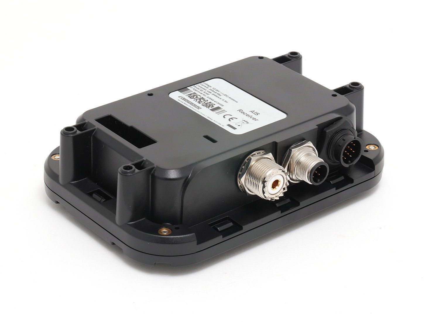
Service: Verify own-ship static and voyage data, sensor inputs, antenna condition, alarms and target reception. Compare transmitted information with approved vessel particulars. Check interfaces to ECDIS, radar and pilot connections where fitted. Refer to the manufacturer documentation for the exact figure for radio-performance and service criteria.
Spare Parts: Carry fuses, power-supply parts, antenna connectors, interface cables and manufacturer-supported display or control modules where justified.
Use Cases: Traffic awareness, collision-avoidance support and regulatory vessel identification.
Seatex AIS 100 unverified
Common Failures & Inspection Points
  • GNSS, VHF antenna or transceiver fault caused by damage, poor connections or electronics failure, resulting in missing targets, transmission alarms or invalid own-ship data
  • Power-supply failure caused by breaker, converter or wiring faults, resulting in loss of the equipment or repeated restarts
  • Network or interface failure caused by damaged cabling, port faults or configuration changes, resulting in loss of data to connected systems
  • Display, processor or control failure caused by hardware or software faults, resulting in frozen indications, alarms or unavailable functions
  • Incorrect configuration or time, position or sensor input caused by setup or upstream faults, resulting in misleading or incomplete information
Service: Inspect sensors, antennas, transducers, cameras, cabling, power supplies and network interfaces applicable to the installed equipment. Compare displayed information with independent references where possible and investigate recurring alarms or missing channels. Verify required outputs to other bridge systems and preserve configuration before approved software or hardware maintenance. Clean exposed sensors and optical surfaces without damaging coatings or seals. Check backup power or recording arrangements where applicable. Refer to the manufacturer documentation for the exact figure for test, calibration, update and recovery procedures.
Spare Parts: Keep fuses, selected power-supply and interface modules, cables or connectors, storage media where applicable and manufacturer-recommended sensor or electronic spares. Replacement core units must remain compatible with the approved bridge installation. Preserve configuration and recorded setup data.
Use Cases: Bridge navigation, monitoring, recording and maritime safety information functions on merchant ships, passenger vessels, offshore units and workboats.
Kongsberg Maritime Seatex AIS 200
Seatex AIS 200 unverified
Common Failures & Inspection Points
  • GNSS, VHF antenna or transceiver fault caused by damage, poor connections or electronics failure, resulting in missing targets, transmission alarms or invalid own-ship data
  • Power-supply failure caused by breaker, converter or wiring faults, resulting in loss of the equipment or repeated restarts
  • Network or interface failure caused by damaged cabling, port faults or configuration changes, resulting in loss of data to connected systems
  • Display, processor or control failure caused by hardware or software faults, resulting in frozen indications, alarms or unavailable functions
  • Incorrect configuration or time, position or sensor input caused by setup or upstream faults, resulting in misleading or incomplete information
Service: Inspect sensors, antennas, transducers, cameras, cabling, power supplies and network interfaces applicable to the installed equipment. Compare displayed information with independent references where possible and investigate recurring alarms or missing channels. Verify required outputs to other bridge systems and preserve configuration before approved software or hardware maintenance. Clean exposed sensors and optical surfaces without damaging coatings or seals. Check backup power or recording arrangements where applicable. Refer to the manufacturer documentation for the exact figure for test, calibration, update and recovery procedures.
Spare Parts: Keep fuses, selected power-supply and interface modules, cables or connectors, storage media where applicable and manufacturer-recommended sensor or electronic spares. Replacement core units must remain compatible with the approved bridge installation. Preserve configuration and recorded setup data.
Use Cases: Bridge navigation, monitoring, recording and maritime safety information functions on merchant ships, passenger vessels, offshore units and workboats.
Kongsberg Maritime Long Range ID-C unverified
Feature
Long Range ID
Common Failures & Inspection Points
  • Loss of sensor input or network communication can remove or freeze displayed data, noticed as invalid-data flags, alarms or missing targets
  • Antenna, transducer or external-sensor contamination or damage can degrade performance, seen as weak, erratic or implausible indications
  • Power-supply or internal electronics faults can cause resets or loss of function, noticed as blank displays, rebooting or system alarms
  • Configuration or calibration drift can produce inaccurate output, seen as disagreement with independent bridge instruments
  • Connector corrosion or water ingress can create intermittent faults, noticed as performance changing with vibration, weather or vessel movement
Service: Inspect displays, external sensors, antennas or transducers, connectors, cabling, power supplies and network interfaces. Compare outputs against independent bridge references where practical and review alarms or self-test indications. Calibration limits and any mandatory test procedure must follow the approved manufacturer and vessel documentation.
Spare Parts: Typical spares include approved fuses, interface cables or connectors, lamps or display consumables, sensor accessories and manufacturer-recommended electronic modules where carried.
Use Cases: Used on merchant ships, offshore vessels, passenger ships and specialized craft as part of the bridge navigation and monitoring suite.
Kongsberg Maritime Inland AIS-C unverified
Feature
Inland AIS
Common Failures & Inspection Points
  • Loss of sensor input or network communication can remove or freeze displayed data, noticed as invalid-data flags, alarms or missing targets
  • Antenna, transducer or external-sensor contamination or damage can degrade performance, seen as weak, erratic or implausible indications
  • Power-supply or internal electronics faults can cause resets or loss of function, noticed as blank displays, rebooting or system alarms
  • Configuration or calibration drift can produce inaccurate output, seen as disagreement with independent bridge instruments
  • Connector corrosion or water ingress can create intermittent faults, noticed as performance changing with vibration, weather or vessel movement
Service: Inspect displays, external sensors, antennas or transducers, connectors, cabling, power supplies and network interfaces. Compare outputs against independent bridge references where practical and review alarms or self-test indications. Calibration limits and any mandatory test procedure must follow the approved manufacturer and vessel documentation.
Spare Parts: Typical spares include approved fuses, interface cables or connectors, lamps or display consumables, sensor accessories and manufacturer-recommended electronic modules where carried.
Use Cases: Used on merchant ships, offshore vessels, passenger ships and specialized craft as part of the bridge navigation and monitoring suite.
Kongsberg Maritime AIS Base Station-C unverified
Feature
AIS Base Station
Common Failures & Inspection Points
  • Loss of sensor input or network communication can remove or freeze displayed data, noticed as invalid-data flags, alarms or missing targets
  • Antenna, transducer or external-sensor contamination or damage can degrade performance, seen as weak, erratic or implausible indications
  • Power-supply or internal electronics faults can cause resets or loss of function, noticed as blank displays, rebooting or system alarms
  • Configuration or calibration drift can produce inaccurate output, seen as disagreement with independent bridge instruments
  • Connector corrosion or water ingress can create intermittent faults, noticed as performance changing with vibration, weather or vessel movement
Service: Inspect displays, external sensors, antennas or transducers, connectors, cabling, power supplies and network interfaces. Compare outputs against independent bridge references where practical and review alarms or self-test indications. Calibration limits and any mandatory test procedure must follow the approved manufacturer and vessel documentation.
Spare Parts: Typical spares include approved fuses, interface cables or connectors, lamps or display consumables, sensor accessories and manufacturer-recommended electronic modules where carried.
Use Cases: Used on merchant ships, offshore vessels, passenger ships and specialized craft as part of the bridge navigation and monitoring suite.
Kongsberg Maritime AIS Receiver Only-C unverified
Feature
AIS Receiver Only
Common Failures & Inspection Points
  • Loss of sensor input or network communication can remove or freeze displayed data, noticed as invalid-data flags, alarms or missing targets
  • Antenna, transducer or external-sensor contamination or damage can degrade performance, seen as weak, erratic or implausible indications
  • Power-supply or internal electronics faults can cause resets or loss of function, noticed as blank displays, rebooting or system alarms
  • Configuration or calibration drift can produce inaccurate output, seen as disagreement with independent bridge instruments
  • Connector corrosion or water ingress can create intermittent faults, noticed as performance changing with vibration, weather or vessel movement
Service: Inspect displays, external sensors, antennas or transducers, connectors, cabling, power supplies and network interfaces. Compare outputs against independent bridge references where practical and review alarms or self-test indications. Calibration limits and any mandatory test procedure must follow the approved manufacturer and vessel documentation.
Spare Parts: Typical spares include approved fuses, interface cables or connectors, lamps or display consumables, sensor accessories and manufacturer-recommended electronic modules where carried.
Use Cases: Used on merchant ships, offshore vessels, passenger ships and specialized craft as part of the bridge navigation and monitoring suite.
Kongsberg Maritime AIS Class A+-C unverified
Feature
AIS Class A+
Common Failures & Inspection Points
  • Loss of sensor input or network communication can remove or freeze displayed data, noticed as invalid-data flags, alarms or missing targets
  • Antenna, transducer or external-sensor contamination or damage can degrade performance, seen as weak, erratic or implausible indications
  • Power-supply or internal electronics faults can cause resets or loss of function, noticed as blank displays, rebooting or system alarms
  • Configuration or calibration drift can produce inaccurate output, seen as disagreement with independent bridge instruments
  • Connector corrosion or water ingress can create intermittent faults, noticed as performance changing with vibration, weather or vessel movement
Service: Inspect displays, external sensors, antennas or transducers, connectors, cabling, power supplies and network interfaces. Compare outputs against independent bridge references where practical and review alarms or self-test indications. Calibration limits and any mandatory test procedure must follow the approved manufacturer and vessel documentation.
Spare Parts: Typical spares include approved fuses, interface cables or connectors, lamps or display consumables, sensor accessories and manufacturer-recommended electronic modules where carried.
Use Cases: Used on merchant ships, offshore vessels, passenger ships and specialized craft as part of the bridge navigation and monitoring suite.
Kongsberg Maritime AIS-SART Combo-C unverified
Feature
AIS-SART Combo
Common Failures & Inspection Points
  • Loss of sensor input or network communication can remove or freeze displayed data, noticed as invalid-data flags, alarms or missing targets
  • Antenna, transducer or external-sensor contamination or damage can degrade performance, seen as weak, erratic or implausible indications
  • Power-supply or internal electronics faults can cause resets or loss of function, noticed as blank displays, rebooting or system alarms
  • Configuration or calibration drift can produce inaccurate output, seen as disagreement with independent bridge instruments
  • Connector corrosion or water ingress can create intermittent faults, noticed as performance changing with vibration, weather or vessel movement
Service: Inspect displays, external sensors, antennas or transducers, connectors, cabling, power supplies and network interfaces. Compare outputs against independent bridge references where practical and review alarms or self-test indications. Calibration limits and any mandatory test procedure must follow the approved manufacturer and vessel documentation.
Spare Parts: Typical spares include approved fuses, interface cables or connectors, lamps or display consumables, sensor accessories and manufacturer-recommended electronic modules where carried.
Use Cases: Used on merchant ships, offshore vessels, passenger ships and specialized craft as part of the bridge navigation and monitoring suite.

Simrad

9
AI80 Class A unverified
IMO Compliant
ja
Common Failures & Inspection Points
  • GNSS, heading or speed-input failure causes invalid or missing dynamic data and produces sensor alarms or incorrect transmitted information
  • VHF antenna or feeder faults reduce transmit and receive range and may cause built-in-test warnings
  • Incorrect static or voyage-data entry results in wrong vessel information being transmitted despite otherwise normal operation
  • Power-supply or network faults cause unit restart, blank display or loss of targets on connected bridge systems
  • Internal transceiver or GPS timing faults cause transmission alarms, missing own-ship reports or inability to receive nearby targets
Service: Verify own-ship static and voyage data, sensor inputs, antenna condition, alarms and target reception. Compare transmitted information with approved vessel particulars and bridge sensors. Check interfaces to ECDIS, radar or pilot plugs where fitted. Radio performance testing and configuration changes must follow approved service procedures.
Spare Parts: Carry fuses, approved power-supply parts, antenna connectors, interface cables and selected display or control components as supported by the manufacturer; maintain current configuration and vessel-data records.
Use Cases: Merchant vessels, passenger ships, offshore units and other craft required or equipped to exchange AIS traffic information.
NAIS-500 unverified
IMO Compliant
ja
Common Failures & Inspection Points
  • GNSS, heading or speed-input failure causes invalid or missing dynamic data and produces sensor alarms or incorrect transmitted information
  • VHF antenna or feeder faults reduce transmit and receive range and may cause built-in-test warnings
  • Incorrect static or voyage-data entry results in wrong vessel information being transmitted despite otherwise normal operation
  • Power-supply or network faults cause unit restart, blank display or loss of targets on connected bridge systems
  • Internal transceiver or GPS timing faults cause transmission alarms, missing own-ship reports or inability to receive nearby targets
Service: Verify own-ship static and voyage data, sensor inputs, antenna condition, alarms and target reception. Compare transmitted information with approved vessel particulars and bridge sensors. Check interfaces to ECDIS, radar or pilot plugs where fitted. Radio performance testing and configuration changes must follow approved service procedures.
Spare Parts: Carry fuses, approved power-supply parts, antenna connectors, interface cables and selected display or control components as supported by the manufacturer; maintain current configuration and vessel-data records.
Use Cases: Merchant vessels, passenger ships, offshore units and other craft required or equipped to exchange AIS traffic information.
NAIS-400 unverified
IMO Compliant
ja
Common Failures & Inspection Points
  • GNSS, heading or speed-input failure causes invalid or missing dynamic data and produces sensor alarms or incorrect transmitted information
  • VHF antenna or feeder faults reduce transmit and receive range and may cause built-in-test warnings
  • Incorrect static or voyage-data entry results in wrong vessel information being transmitted despite otherwise normal operation
  • Power-supply or network faults cause unit restart, blank display or loss of targets on connected bridge systems
  • Internal transceiver or GPS timing faults cause transmission alarms, missing own-ship reports or inability to receive nearby targets
Service: Verify own-ship static and voyage data, sensor inputs, antenna condition, alarms and target reception. Compare transmitted information with approved vessel particulars and bridge sensors. Check interfaces to ECDIS, radar or pilot plugs where fitted. Radio performance testing and configuration changes must follow approved service procedures.
Spare Parts: Carry fuses, approved power-supply parts, antenna connectors, interface cables and selected display or control components as supported by the manufacturer; maintain current configuration and vessel-data records.
Use Cases: Merchant vessels, passenger ships, offshore units and other craft required or equipped to exchange AIS traffic information.
Simrad AIS Bridge Console-C unverified
Installation
Bridge Console
Common Failures & Inspection Points
  • Antenna, feeder or connector corrosion causes weak reception, poor transmission or high reflected-power indications
  • Power-supply or backup-battery faults cause resets or loss of availability during main-power failure
  • GNSS or data-interface loss causes missing position or identity information in transmitted messages
  • Microphone, handset, speaker or operator-control faults impair communication despite the main unit remaining powered
  • Configuration or programming errors can cause incorrect identity, channel or service behaviour
Service: Carry out the approved self-tests and operational checks without generating false distress alerts. Inspect antennas, feeders, connectors, earth or bonding arrangements where applicable, reserve supply and interfaces to navigation data. Verify programmed identity information and GMDSS records; exact radio tests, power measurements and configuration procedures must follow manufacturer and statutory documentation.
Spare Parts: Keep approved fuses, handset or microphone parts, antenna connectors, selected cables, printer consumables where fitted and critical power-supply or interface modules according to the vessel's GMDSS spares arrangement.
Use Cases: Used on seagoing vessels for distress, safety and routine maritime communications as part of the bridge and GMDSS installation.
Simrad AIS Mast-Head-C unverified
Installation
Mast-Head
Common Failures & Inspection Points
  • Loss of supply power from a tripped breaker, failed power unit, loose connection, or depleted reserve battery causes a dead unit, rebooting, or failure to transmit
  • Antenna, feeder, connector, or matching fault caused by corrosion, water ingress, or physical damage results in poor range, failed transmission, or weak received signals
  • Control-panel, display, keypad, or software faults can prevent channel selection, message handling, or normal operator input
  • Interface or position-data failure caused by wiring, configuration, or sensor faults can remove position information or connected-system data
  • Internal transmitter, receiver, or modem faults caused by component ageing or overheating can produce intermittent communication, alarms, or inability to establish a link
Service: Verify primary and reserve power, antenna and feeder condition, distress and safety functions permitted for routine testing, interfaces, audio quality, time and position inputs, and logged self-test results. Any regulatory test or adjustment must follow the vessel's radio procedures and manufacturer documentation.
Spare Parts: Carry the model-specific fuses, approved power-supply items, handset or microphone accessories, connector and sealing items, and critical interface or antenna components recommended by the manufacturer and vessel radio-maintenance plan.
Use Cases: Used on SOLAS merchant ships, offshore vessels, passenger ships, fishing vessels, workboats, and other craft requiring marine radio, distress, safety, or navigation communications.
Simrad AIS Standalone-C unverified
Installation
Standalone
Common Failures & Inspection Points
  • Antenna, feeder or tuning fault caused by corrosion, damaged cabling or poor connections, resulting in weak transmission, reception problems or equipment alarms
  • Power-supply or backup-battery failure caused by charger defects, aged batteries or wiring faults, resulting in loss of availability when main power is removed
  • Transmitter or receiver failure caused by RF-component or electronic faults, resulting in inability to establish communications or receive expected traffic
  • Position or time-input failure caused by GNSS or network faults, resulting in missing or incorrect data in distress or DSC functions
  • Control, display or software fault caused by hardware failure or configuration problems, resulting in frozen controls, error messages or unavailable functions
Service: Perform operational and self-tests permitted by the vessel's procedures without generating unintended distress alerts. Inspect antennas, feeders, grounding, power supplies, backup batteries and connected navigation-data inputs. Verify station identity, position input, time and configured communication services against approved records. Check printers, handsets, microphones and alarm interfaces where fitted. Maintain software, licenses and service subscriptions required by the installed system. Refer to manufacturer and regulatory documentation for exact test methods, battery criteria and approved servicing.
Spare Parts: Keep fuses, handset or microphone accessories, printer consumables where applicable, selected power-supply components and manufacturer-recommended electronic spares. Antenna or feeder repair materials and backup-battery arrangements should reflect the vessel's redundancy plan. Preserve type approval and programmed identity when replacing core units.
Use Cases: Distress, urgency, safety and routine maritime communications within the vessel's GMDSS and operational communications fit.
Simrad AIS Class A IMO-C unverified
Installation
Class A IMO
Common Failures & Inspection Points
  • Antenna, feeder or tuning fault caused by corrosion, damaged cabling or poor connections, resulting in weak transmission, reception problems or equipment alarms
  • Power-supply or backup-battery failure caused by charger defects, aged batteries or wiring faults, resulting in loss of availability when main power is removed
  • Transmitter or receiver failure caused by RF-component or electronic faults, resulting in inability to establish communications or receive expected traffic
  • Position or time-input failure caused by GNSS or network faults, resulting in missing or incorrect data in distress or DSC functions
  • Control, display or software fault caused by hardware failure or configuration problems, resulting in frozen controls, error messages or unavailable functions
Service: Perform operational and self-tests permitted by the vessel's procedures without generating unintended distress alerts. Inspect antennas, feeders, grounding, power supplies, backup batteries and connected navigation-data inputs. Verify station identity, position input, time and configured communication services against approved records. Check printers, handsets, microphones and alarm interfaces where fitted. Maintain software, licenses and service subscriptions required by the installed system. Refer to manufacturer and regulatory documentation for exact test methods, battery criteria and approved servicing.
Spare Parts: Keep fuses, handset or microphone accessories, printer consumables where applicable, selected power-supply components and manufacturer-recommended electronic spares. Antenna or feeder repair materials and backup-battery arrangements should reflect the vessel's redundancy plan. Preserve type approval and programmed identity when replacing core units.
Use Cases: Distress, urgency, safety and routine maritime communications within the vessel's GMDSS and operational communications fit.
Simrad AIS Class B CS-C unverified
Installation
Class B CS
Common Failures & Inspection Points
  • Antenna, feeder or tuning fault caused by corrosion, damaged cabling or poor connections, resulting in weak transmission, reception problems or equipment alarms
  • Power-supply or backup-battery failure caused by charger defects, aged batteries or wiring faults, resulting in loss of availability when main power is removed
  • Transmitter or receiver failure caused by RF-component or electronic faults, resulting in inability to establish communications or receive expected traffic
  • Position or time-input failure caused by GNSS or network faults, resulting in missing or incorrect data in distress or DSC functions
  • Control, display or software fault caused by hardware failure or configuration problems, resulting in frozen controls, error messages or unavailable functions
Service: Perform operational and self-tests permitted by the vessel's procedures without generating unintended distress alerts. Inspect antennas, feeders, grounding, power supplies, backup batteries and connected navigation-data inputs. Verify station identity, position input, time and configured communication services against approved records. Check printers, handsets, microphones and alarm interfaces where fitted. Maintain software, licenses and service subscriptions required by the installed system. Refer to manufacturer and regulatory documentation for exact test methods, battery criteria and approved servicing.
Spare Parts: Keep fuses, handset or microphone accessories, printer consumables where applicable, selected power-supply components and manufacturer-recommended electronic spares. Antenna or feeder repair materials and backup-battery arrangements should reflect the vessel's redundancy plan. Preserve type approval and programmed identity when replacing core units.
Use Cases: Distress, urgency, safety and routine maritime communications within the vessel's GMDSS and operational communications fit.
Simrad AIS Class B SOTDMA-C unverified
Installation
Class B SOTDMA
Common Failures & Inspection Points
  • Antenna, feeder or connector corrosion causes weak reception, poor transmission or high reflected-power indications
  • Power-supply or backup-battery faults cause resets or loss of availability during main-power failure
  • GNSS or data-interface loss causes missing position or identity information in transmitted messages
  • Microphone, handset, speaker or operator-control faults impair communication despite the main unit remaining powered
  • Configuration or programming errors can cause incorrect identity, channel or service behaviour
Service: Carry out the approved self-tests and operational checks without generating false distress alerts. Inspect antennas, feeders, connectors, earth or bonding arrangements where applicable, reserve supply and interfaces to navigation data. Verify programmed identity information and GMDSS records; exact radio tests, power measurements and configuration procedures must follow manufacturer and statutory documentation.
Spare Parts: Keep approved fuses, handset or microphone parts, antenna connectors, selected cables, printer consumables where fitted and critical power-supply or interface modules according to the vessel's GMDSS spares arrangement.
Use Cases: Used on seagoing vessels for distress, safety and routine maritime communications as part of the bridge and GMDSS installation.

Vesper Marine

6
Vesper Cortex M1 unverified
Class
A
Common Failures & Inspection Points
  • Antenna, feeder or tuning fault caused by corrosion, damaged cabling or poor connections, resulting in weak transmission, reception problems or equipment alarms
  • Power-supply or backup-battery failure caused by charger defects, aged batteries or wiring faults, resulting in loss of availability when main power is removed
  • Transmitter or receiver failure caused by RF-component or electronic faults, resulting in inability to establish communications or receive expected traffic
  • Position or time-input failure caused by GNSS or network faults, resulting in missing or incorrect data in distress or DSC functions
  • Control, display or software fault caused by hardware failure or configuration problems, resulting in frozen controls, error messages or unavailable functions
Service: Perform operational and self-tests permitted by the vessel's procedures without generating unintended distress alerts. Inspect antennas, feeders, grounding, power supplies, backup batteries and connected navigation-data inputs. Verify station identity, position input, time and configured communication services against approved records. Check printers, handsets, microphones and alarm interfaces where fitted. Maintain software, licenses and service subscriptions required by the installed system. Refer to manufacturer and regulatory documentation for exact test methods, battery criteria and approved servicing.
Spare Parts: Keep fuses, handset or microphone accessories, printer consumables where applicable, selected power-supply components and manufacturer-recommended electronic spares. Antenna or feeder repair materials and backup-battery arrangements should reflect the vessel's redundancy plan. Preserve type approval and programmed identity when replacing core units.
Use Cases: Distress, urgency, safety and routine maritime communications within the vessel's GMDSS and operational communications fit.
Vesper XB-8000 unverified
Class
B
Common Failures & Inspection Points
  • Loss of supply power from a tripped breaker, failed power unit, loose connection, or depleted reserve battery causes a dead unit, rebooting, or failure to transmit
  • Antenna, feeder, connector, or matching fault caused by corrosion, water ingress, or physical damage results in poor range, failed transmission, or weak received signals
  • Control-panel, display, keypad, or software faults can prevent channel selection, message handling, or normal operator input
  • Interface or position-data failure caused by wiring, configuration, or sensor faults can remove position information or connected-system data
  • Internal transmitter, receiver, or modem faults caused by component ageing or overheating can produce intermittent communication, alarms, or inability to establish a link
Service: Verify primary and reserve power, antenna and feeder condition, distress and safety functions permitted for routine testing, interfaces, audio quality, time and position inputs, and logged self-test results. Any regulatory test or adjustment must follow the vessel's radio procedures and manufacturer documentation.
Spare Parts: Carry the model-specific fuses, approved power-supply items, handset or microphone accessories, connector and sealing items, and critical interface or antenna components recommended by the manufacturer and vessel radio-maintenance plan.
Use Cases: Used on SOLAS merchant ships, offshore vessels, passenger ships, fishing vessels, workboats, and other craft requiring marine radio, distress, safety, or navigation communications.
Vesper WatchMate Vision2 unverified
Class
A
Common Failures & Inspection Points
  • Loss of supply power from a tripped breaker, failed power unit, loose connection, or depleted reserve battery causes a dead unit, rebooting, or failure to transmit
  • Antenna, feeder, connector, or matching fault caused by corrosion, water ingress, or physical damage results in poor range, failed transmission, or weak received signals
  • Control-panel, display, keypad, or software faults can prevent channel selection, message handling, or normal operator input
  • Interface or position-data failure caused by wiring, configuration, or sensor faults can remove position information or connected-system data
  • Internal transmitter, receiver, or modem faults caused by component ageing or overheating can produce intermittent communication, alarms, or inability to establish a link
Service: Verify primary and reserve power, antenna and feeder condition, distress and safety functions permitted for routine testing, interfaces, audio quality, time and position inputs, and logged self-test results. Any regulatory test or adjustment must follow the vessel's radio procedures and manufacturer documentation.
Spare Parts: Carry the model-specific fuses, approved power-supply items, handset or microphone accessories, connector and sealing items, and critical interface or antenna components recommended by the manufacturer and vessel radio-maintenance plan.
Use Cases: Used on SOLAS merchant ships, offshore vessels, passenger ships, fishing vessels, workboats, and other craft requiring marine radio, distress, safety, or navigation communications.
Cortex M1 Mk2 unverified
IMO Compliant
ja
Common Failures & Inspection Points
  • Transmitter or receiver failure caused by RF, antenna, feeder or power faults, noticed as poor range, failed checks or loss of reception
  • Antenna/feed-line deterioration caused by corrosion, water ingress or mechanical damage, noticed as intermittent operation or reduced range
  • Control or audio failure caused by handset, microphone, display, keypad or controller faults, noticed as inability to operate normal functions
  • Position/identity or data-interface failure caused by wiring or configuration faults, noticed as missing or incorrect safety data
  • Power-source failure caused by breaker, fuse, converter or emergency-supply faults, noticed as dead equipment or loss of required GMDSS availability
Service: Carry out the permitted operational/self-tests, inspect antennas, feeders, connectors, controls and cooling, and verify normal and emergency power where required. Check vessel identity, position and interfaces appropriate to the equipment type and review recurring alarms or logbook entries. A radio surveyor should confirm the installation and programmed data against the approved radio documentation.
Spare Parts: Carry fuses, approved handsets/microphones or control accessories where applicable, antenna connectors and feeder repair items, selected power-supply components and manufacturer-recommended interface/control spares. The spare scale should match the vessel's declared GMDSS maintenance method.
Use Cases: Used on merchant, offshore, passenger and workboat fleets for distress, safety and routine maritime communications according to the equipment's approved GMDSS function.
Cortex H1 unverified
IMO Compliant
ja
Common Failures & Inspection Points
  • Transmitter or receiver failure caused by RF, antenna, feeder or power faults, noticed as poor range, failed checks or loss of reception
  • Antenna/feed-line deterioration caused by corrosion, water ingress or mechanical damage, noticed as intermittent operation or reduced range
  • Control or audio failure caused by handset, microphone, display, keypad or controller faults, noticed as inability to operate normal functions
  • Position/identity or data-interface failure caused by wiring or configuration faults, noticed as missing or incorrect safety data
  • Power-source failure caused by breaker, fuse, converter or emergency-supply faults, noticed as dead equipment or loss of required GMDSS availability
Service: Carry out the permitted operational/self-tests, inspect antennas, feeders, connectors, controls and cooling, and verify normal and emergency power where required. Check vessel identity, position and interfaces appropriate to the equipment type and review recurring alarms or logbook entries. A radio surveyor should confirm the installation and programmed data against the approved radio documentation.
Spare Parts: Carry fuses, approved handsets/microphones or control accessories where applicable, antenna connectors and feeder repair items, selected power-supply components and manufacturer-recommended interface/control spares. The spare scale should match the vessel's declared GMDSS maintenance method.
Use Cases: Used on merchant, offshore, passenger and workboat fleets for distress, safety and routine maritime communications according to the equipment's approved GMDSS function.
Vesper Marine WatchMate Vision3
WatchMate Vision3 unverified
IMO Compliant
ja
Common Failures & Inspection Points
  • Antenna, feeder or tuning fault caused by corrosion, damaged cabling or poor connections, resulting in weak transmission, reception problems or equipment alarms
  • Power-supply or backup-battery failure caused by charger defects, aged batteries or wiring faults, resulting in loss of availability when main power is removed
  • Transmitter or receiver failure caused by RF-component or electronic faults, resulting in inability to establish communications or receive expected traffic
  • Position or time-input failure caused by GNSS or network faults, resulting in missing or incorrect data in distress or DSC functions
  • Control, display or software fault caused by hardware failure or configuration problems, resulting in frozen controls, error messages or unavailable functions
Service: Perform operational and self-tests permitted by the vessel's procedures without generating unintended distress alerts. Inspect antennas, feeders, grounding, power supplies, backup batteries and connected navigation-data inputs. Verify station identity, position input, time and configured communication services against approved records. Check printers, handsets, microphones and alarm interfaces where fitted. Maintain software, licenses and service subscriptions required by the installed system. Refer to manufacturer and regulatory documentation for exact test methods, battery criteria and approved servicing.
Spare Parts: Keep fuses, handset or microphone accessories, printer consumables where applicable, selected power-supply components and manufacturer-recommended electronic spares. Antenna or feeder repair materials and backup-battery arrangements should reflect the vessel's redundancy plan. Preserve type approval and programmed identity when replacing core units.
Use Cases: Distress, urgency, safety and routine maritime communications within the vessel's GMDSS and operational communications fit.

Digital Yacht

4
AISnet unverified
Common Failures & Inspection Points
  • Sensor or antenna degradation caused by contamination, damage, ageing or poor exposure can produce missing, unstable or implausible data
  • Connector, cable or network faults caused by vibration, corrosion or disturbed terminations can cause intermittent data loss or interface alarms
  • Power-supply or internal electronics failure caused by ageing, heat or poor ventilation can result in resets, blank indications or complete loss of function
  • Configuration or software errors after service or replacement can cause incorrect data, rejected inputs or loss of communication with other bridge equipment
  • Mechanical damage or water ingress at exposed components can lead to erratic readings, repeated alarms or loss of the affected channel
Service: Inspect exposed sensors or antennas, cable routes, connectors, power supplies, displays and network interfaces. Confirm that indicated or recorded data is plausible and that built-in tests and alarms operate. Compare configuration and test results with the vessel's approved records and manufacturer documentation.
Spare Parts: Keep maker-recommended fuses, connectors, sensor accessories, fans, interface or power modules and other approved line-replaceable items that match the installed configuration.
Use Cases: Commercial ships, passenger vessels, offshore vessels and workboats requiring bridge navigation, recording, environmental or traffic information.
AIT2000 unverified
Common Failures & Inspection Points
  • Sensor or antenna degradation caused by contamination, damage, ageing or poor exposure can produce missing, unstable or implausible data
  • Connector, cable or network faults caused by vibration, corrosion or disturbed terminations can cause intermittent data loss or interface alarms
  • Power-supply or internal electronics failure caused by ageing, heat or poor ventilation can result in resets, blank indications or complete loss of function
  • Configuration or software errors after service or replacement can cause incorrect data, rejected inputs or loss of communication with other bridge equipment
  • Mechanical damage or water ingress at exposed components can lead to erratic readings, repeated alarms or loss of the affected channel
Service: Inspect exposed sensors or antennas, cable routes, connectors, power supplies, displays and network interfaces. Confirm that indicated or recorded data is plausible and that built-in tests and alarms operate. Compare configuration and test results with the vessel's approved records and manufacturer documentation.
Spare Parts: Keep maker-recommended fuses, connectors, sensor accessories, fans, interface or power modules and other approved line-replaceable items that match the installed configuration.
Use Cases: Commercial ships, passenger vessels, offshore vessels and workboats requiring bridge navigation, recording, environmental or traffic information.
AIT3000 unverified
Common Failures & Inspection Points
  • Sensor or antenna degradation caused by contamination, damage, ageing or poor exposure can produce missing, unstable or implausible data
  • Connector, cable or network faults caused by vibration, corrosion or disturbed terminations can cause intermittent data loss or interface alarms
  • Power-supply or internal electronics failure caused by ageing, heat or poor ventilation can result in resets, blank indications or complete loss of function
  • Configuration or software errors after service or replacement can cause incorrect data, rejected inputs or loss of communication with other bridge equipment
  • Mechanical damage or water ingress at exposed components can lead to erratic readings, repeated alarms or loss of the affected channel
Service: Inspect exposed sensors or antennas, cable routes, connectors, power supplies, displays and network interfaces. Confirm that indicated or recorded data is plausible and that built-in tests and alarms operate. Compare configuration and test results with the vessel's approved records and manufacturer documentation.
Spare Parts: Keep maker-recommended fuses, connectors, sensor accessories, fans, interface or power modules and other approved line-replaceable items that match the installed configuration.
Use Cases: Commercial ships, passenger vessels, offshore vessels and workboats requiring bridge navigation, recording, environmental or traffic information.
iAISTX unverified
Common Failures & Inspection Points
  • Sensor or antenna degradation caused by contamination, damage, ageing or poor exposure can produce missing, unstable or implausible data
  • Connector, cable or network faults caused by vibration, corrosion or disturbed terminations can cause intermittent data loss or interface alarms
  • Power-supply or internal electronics failure caused by ageing, heat or poor ventilation can result in resets, blank indications or complete loss of function
  • Configuration or software errors after service or replacement can cause incorrect data, rejected inputs or loss of communication with other bridge equipment
  • Mechanical damage or water ingress at exposed components can lead to erratic readings, repeated alarms or loss of the affected channel
Service: Inspect exposed sensors or antennas, cable routes, connectors, power supplies, displays and network interfaces. Confirm that indicated or recorded data is plausible and that built-in tests and alarms operate. Compare configuration and test results with the vessel's approved records and manufacturer documentation.
Spare Parts: Keep maker-recommended fuses, connectors, sensor accessories, fans, interface or power modules and other approved line-replaceable items that match the installed configuration.
Use Cases: Commercial ships, passenger vessels, offshore vessels and workboats requiring bridge navigation, recording, environmental or traffic information.

Alltek Marine

3
AIS-T1 unverified
Common Failures & Inspection Points
  • Sensor or antenna degradation caused by contamination, damage, ageing or poor exposure can produce missing, unstable or implausible data
  • Connector, cable or network faults caused by vibration, corrosion or disturbed terminations can cause intermittent data loss or interface alarms
  • Power-supply or internal electronics failure caused by ageing, heat or poor ventilation can result in resets, blank indications or complete loss of function
  • Configuration or software errors after service or replacement can cause incorrect data, rejected inputs or loss of communication with other bridge equipment
  • Mechanical damage or water ingress at exposed components can lead to erratic readings, repeated alarms or loss of the affected channel
Service: Inspect exposed sensors or antennas, cable routes, connectors, power supplies, displays and network interfaces. Confirm that indicated or recorded data is plausible and that built-in tests and alarms operate. Compare configuration and test results with the vessel's approved records and manufacturer documentation.
Spare Parts: Keep maker-recommended fuses, connectors, sensor accessories, fans, interface or power modules and other approved line-replaceable items that match the installed configuration.
Use Cases: Commercial ships, passenger vessels, offshore vessels and workboats requiring bridge navigation, recording, environmental or traffic information.
AIS-T2 unverified
Common Failures & Inspection Points
  • Sensor or antenna degradation caused by contamination, damage, ageing or poor exposure can produce missing, unstable or implausible data
  • Connector, cable or network faults caused by vibration, corrosion or disturbed terminations can cause intermittent data loss or interface alarms
  • Power-supply or internal electronics failure caused by ageing, heat or poor ventilation can result in resets, blank indications or complete loss of function
  • Configuration or software errors after service or replacement can cause incorrect data, rejected inputs or loss of communication with other bridge equipment
  • Mechanical damage or water ingress at exposed components can lead to erratic readings, repeated alarms or loss of the affected channel
Service: Inspect exposed sensors or antennas, cable routes, connectors, power supplies, displays and network interfaces. Confirm that indicated or recorded data is plausible and that built-in tests and alarms operate. Compare configuration and test results with the vessel's approved records and manufacturer documentation.
Spare Parts: Keep maker-recommended fuses, connectors, sensor accessories, fans, interface or power modules and other approved line-replaceable items that match the installed configuration.
Use Cases: Commercial ships, passenger vessels, offshore vessels and workboats requiring bridge navigation, recording, environmental or traffic information.
AIS-R1 unverified
Common Failures & Inspection Points
  • Sensor or antenna degradation caused by contamination, damage, ageing or poor exposure can produce missing, unstable or implausible data
  • Connector, cable or network faults caused by vibration, corrosion or disturbed terminations can cause intermittent data loss or interface alarms
  • Power-supply or internal electronics failure caused by ageing, heat or poor ventilation can result in resets, blank indications or complete loss of function
  • Configuration or software errors after service or replacement can cause incorrect data, rejected inputs or loss of communication with other bridge equipment
  • Mechanical damage or water ingress at exposed components can lead to erratic readings, repeated alarms or loss of the affected channel
Service: Inspect exposed sensors or antennas, cable routes, connectors, power supplies, displays and network interfaces. Confirm that indicated or recorded data is plausible and that built-in tests and alarms operate. Compare configuration and test results with the vessel's approved records and manufacturer documentation.
Spare Parts: Keep maker-recommended fuses, connectors, sensor accessories, fans, interface or power modules and other approved line-replaceable items that match the installed configuration.
Use Cases: Commercial ships, passenger vessels, offshore vessels and workboats requiring bridge navigation, recording, environmental or traffic information.

Sailor / Cobham

3
6280 AIS Class A unverified
Class
A
IMO Compliant
ja
Common Failures & Inspection Points
  • GNSS, heading or speed-input failure causes invalid dynamic data and sensor alarms
  • VHF antenna or feeder faults reduce transmit and receive range and may trigger built-in-test warnings
  • Incorrect static or voyage data results in wrong vessel information being transmitted
  • Power-supply or network faults cause unit resets, blank displays or loss of target data to bridge systems
  • Internal transceiver or timing faults cause transmission alarms or missing nearby targets
Service: Verify own-ship static and voyage data, sensor inputs, antenna condition, alarms and target reception. Compare transmitted information with approved vessel particulars. Check interfaces to ECDIS, radar and pilot connections where fitted. Radio-performance testing should follow approved service procedures.
Spare Parts: Carry fuses, power-supply parts, antenna connectors, interface cables and manufacturer-supported display or control modules where justified.
Use Cases: Traffic awareness, collision avoidance support and regulatory reporting on merchant and passenger vessels.
SAILOR SSAS unverified
Type
SSAS
IMO Compliant
ja
Common Failures & Inspection Points
  • Sensor, antenna or transducer fault, typically indicated by missing, unstable or implausible navigation data
  • Power-supply or processor failure, typically indicated by blank display, rebooting or unavailable function
  • Network/interface fault, typically indicated by missing data on connected bridge systems or communication alarms
  • Cable/connector corrosion or water ingress, typically indicated by intermittent operation or signal loss
  • Recording/storage or software fault on recorder-type equipment, typically indicated by data gaps, recording alarms or failed playback
Service: Check self-tests, sensor/transducer condition, data interfaces, time/position inputs, recording status where applicable, power supplies and alarm history; performance tests and calibration must follow approved manufacturer and statutory procedures.
Spare Parts: Carry critical fuses, power supplies, interface modules, storage media where approved, sensors/transducers or display peripherals according to equipment criticality.
Use Cases: Used on merchant, passenger, offshore and naval vessels for navigation, bridge situational awareness, environmental sensing and voyage-data recording. This entry applies specifically to the AIS Transponder variant identified as Sailor / Cobham SAILOR SSAS.
SAILOR 6006 unverified
Type
SSAS
IMO Compliant
ja
Common Failures & Inspection Points
  • Sensor, antenna or transducer fault, typically indicated by missing, unstable or implausible navigation data
  • Power-supply or processor failure, typically indicated by blank display, rebooting or unavailable function
  • Network/interface fault, typically indicated by missing data on connected bridge systems or communication alarms
  • Cable/connector corrosion or water ingress, typically indicated by intermittent operation or signal loss
  • Recording/storage or software fault on recorder-type equipment, typically indicated by data gaps, recording alarms or failed playback
Service: Check self-tests, sensor/transducer condition, data interfaces, time/position inputs, recording status where applicable, power supplies and alarm history; performance tests and calibration must follow approved manufacturer and statutory procedures.
Spare Parts: Carry critical fuses, power supplies, interface modules, storage media where approved, sensors/transducers or display peripherals according to equipment criticality.
Use Cases: Used on merchant, passenger, offshore and naval vessels for navigation, bridge situational awareness, environmental sensing and voyage-data recording. This entry applies specifically to the AIS Transponder variant identified as Sailor / Cobham SAILOR 6006.

SRT Marine Technology

3
SRT Marine Technology SRT AIS-100
SRT AIS-100 unverified
Class
B
Common Failures & Inspection Points
  • GNSS, heading or speed-input failure causes invalid dynamic data and sensor alarms
  • VHF antenna or feeder faults reduce transmit and receive range and may trigger built-in-test warnings
  • Incorrect static or voyage data results in wrong vessel information being transmitted
  • Power-supply or network faults cause unit resets, blank displays or loss of target data to bridge systems
  • Internal transceiver or timing faults cause transmission alarms or missing nearby targets
Service: Verify own-ship static and voyage data, sensor inputs, antenna condition, alarms and target reception. Compare transmitted information with approved vessel particulars. Check interfaces to ECDIS, radar and pilot connections where fitted. Radio-performance testing should follow approved service procedures.
Spare Parts: Carry fuses, power-supply parts, antenna connectors, interface cables and manufacturer-supported display or control modules where justified.
Use Cases: Traffic awareness, collision avoidance support and regulatory reporting on merchant and passenger vessels.
SRT Marine Technology SRT AIS-200
SRT AIS-200 unverified
Class
B
Common Failures & Inspection Points
  • GNSS, heading or speed-input failure causes invalid dynamic data and sensor alarms
  • VHF antenna or feeder faults reduce transmit and receive range and may trigger built-in-test warnings
  • Incorrect static or voyage data results in wrong vessel information being transmitted
  • Power-supply or network faults cause unit resets, blank displays or loss of target data to bridge systems
  • Internal transceiver or timing faults cause transmission alarms or missing nearby targets
Service: Verify own-ship static and voyage data, sensor inputs, antenna condition, alarms and target reception. Compare transmitted information with approved vessel particulars. Check interfaces to ECDIS, radar and pilot connections where fitted. Radio-performance testing should follow approved service procedures.
Spare Parts: Carry fuses, power-supply parts, antenna connectors, interface cables and manufacturer-supported display or control modules where justified.
Use Cases: Traffic awareness, collision avoidance support and regulatory reporting on merchant and passenger vessels.
SRT AIS-400 unverified
Class
A
Common Failures & Inspection Points
  • GNSS, heading or speed-input failure causes invalid dynamic data and sensor alarms
  • VHF antenna or feeder faults reduce transmit and receive range and may trigger built-in-test warnings
  • Incorrect static or voyage data results in wrong vessel information being transmitted
  • Power-supply or network faults cause unit resets, blank displays or loss of target data to bridge systems
  • Internal transceiver or timing faults cause transmission alarms or missing nearby targets
Service: Verify own-ship static and voyage data, sensor inputs, antenna condition, alarms and target reception. Compare transmitted information with approved vessel particulars. Check interfaces to ECDIS, radar and pilot connections where fitted. Radio-performance testing should follow approved service procedures.
Spare Parts: Carry fuses, power-supply parts, antenna connectors, interface cables and manufacturer-supported display or control modules where justified.
Use Cases: Traffic awareness, collision avoidance support and regulatory reporting on merchant and passenger vessels.

Pole Star

2
Polaris SSAS unverified
Type
SSAS/LRIT
IMO Compliant
ja
Common Failures & Inspection Points
  • Loss of primary or reserve power from a tripped breaker, failed power unit, loose connection, or depleted battery causes a dead unit, rebooting, or failed transmission
  • Antenna, feeder, connector, or matching faults from corrosion, water ingress, or physical damage cause poor range or weak received signals
  • Control-panel, display, keypad, or software faults prevent channel selection, message handling, or operator input
  • Interface or position-data failure from wiring, configuration, or sensor faults removes position or connected-system data
  • Internal transmitter, receiver, or modem faults from component ageing or overheating cause intermittent communication, alarms, or inability to establish a link
Service: Verify primary and reserve power, antenna and feeder condition, permitted distress/safety self-tests, interfaces, audio quality, time and position inputs, and logged faults. Regulatory tests and adjustments must follow vessel radio procedures and manufacturer documentation.
Spare Parts: Carry model-specific fuses, approved power-supply items, handset or microphone accessories where relevant, connector and sealing items, and critical interface or antenna components recommended by the manufacturer.
Use Cases: Used on SOLAS merchant ships, offshore vessels, passenger ships, fishing vessels, workboats, and other craft requiring marine radio, distress, safety, or navigation communications.
Polaris LRIT unverified
Type
SSAS/LRIT
IMO Compliant
ja
Common Failures & Inspection Points
  • Loss of primary or reserve power from a tripped breaker, failed power unit, loose connection, or depleted battery causes a dead unit, rebooting, or failed transmission
  • Antenna, feeder, connector, or matching faults from corrosion, water ingress, or physical damage cause poor range or weak received signals
  • Control-panel, display, keypad, or software faults prevent channel selection, message handling, or operator input
  • Interface or position-data failure from wiring, configuration, or sensor faults removes position or connected-system data
  • Internal transmitter, receiver, or modem faults from component ageing or overheating cause intermittent communication, alarms, or inability to establish a link
Service: Verify primary and reserve power, antenna and feeder condition, permitted distress/safety self-tests, interfaces, audio quality, time and position inputs, and logged faults. Regulatory tests and adjustments must follow vessel radio procedures and manufacturer documentation.
Spare Parts: Carry model-specific fuses, approved power-supply items, handset or microphone accessories where relevant, connector and sealing items, and critical interface or antenna components recommended by the manufacturer.
Use Cases: Used on SOLAS merchant ships, offshore vessels, passenger ships, fishing vessels, workboats, and other craft requiring marine radio, distress, safety, or navigation communications.

SAAB

2
SAAB R5 AIS unverified
Class
A
IMO Compliant
ja
Common Failures & Inspection Points
  • GNSS, heading or speed-input failure causes invalid or missing dynamic data and produces sensor alarms or incorrect transmitted information
  • VHF antenna or feeder faults reduce transmit and receive range and may cause built-in-test warnings
  • Incorrect static or voyage-data entry results in wrong vessel information being transmitted despite otherwise normal operation
  • Power-supply or network faults cause unit restart, blank display or loss of targets on connected bridge systems
  • Internal transceiver or GPS timing faults cause transmission alarms, missing own-ship reports or inability to receive nearby targets
Service: Verify own-ship static and voyage data, sensor inputs, antenna condition, alarms and target reception. Compare transmitted information with approved vessel particulars and bridge sensors. Check interfaces to ECDIS, radar or pilot plugs where fitted. Radio performance testing and configuration changes must follow approved service procedures.
Spare Parts: Carry fuses, approved power-supply parts, antenna connectors, interface cables and selected display or control components as supported by the manufacturer; maintain current configuration and vessel-data records.
Use Cases: Merchant vessels, passenger ships, offshore units and other craft required or equipped to exchange AIS traffic information.
SAAB R5 SOLID unverified
Class
A
IMO Compliant
ja
Common Failures & Inspection Points
  • GNSS, heading or speed-input failure causes invalid or missing dynamic data and produces sensor alarms or incorrect transmitted information
  • VHF antenna or feeder faults reduce transmit and receive range and may cause built-in-test warnings
  • Incorrect static or voyage-data entry results in wrong vessel information being transmitted despite otherwise normal operation
  • Power-supply or network faults cause unit restart, blank display or loss of targets on connected bridge systems
  • Internal transceiver or GPS timing faults cause transmission alarms, missing own-ship reports or inability to receive nearby targets
Service: Verify own-ship static and voyage data, sensor inputs, antenna condition, alarms and target reception. Compare transmitted information with approved vessel particulars and bridge sensors. Check interfaces to ECDIS, radar or pilot plugs where fitted. Radio performance testing and configuration changes must follow approved service procedures.
Spare Parts: Carry fuses, approved power-supply parts, antenna connectors, interface cables and selected display or control components as supported by the manufacturer; maintain current configuration and vessel-data records.
Use Cases: Merchant vessels, passenger ships, offshore units and other craft required or equipped to exchange AIS traffic information.

Weatherdock

2
easyTRX2S-iS unverified
IMO Compliant
ja
Common Failures & Inspection Points
  • Transmitter or receiver failure caused by RF, antenna, feeder or power faults, noticed as poor range, failed checks or loss of reception
  • Antenna/feed-line deterioration caused by corrosion, water ingress or mechanical damage, noticed as intermittent operation or reduced range
  • Control or audio failure caused by handset, microphone, display, keypad or controller faults, noticed as inability to operate normal functions
  • Position/identity or data-interface failure caused by wiring or configuration faults, noticed as missing or incorrect safety data
  • Power-source failure caused by breaker, fuse, converter or emergency-supply faults, noticed as dead equipment or loss of required GMDSS availability
Service: Carry out the permitted operational/self-tests, inspect antennas, feeders, connectors, controls and cooling, and verify normal and emergency power where required. Check vessel identity, position and interfaces appropriate to the equipment type and review recurring alarms or logbook entries. A radio surveyor should confirm the installation and programmed data against the approved radio documentation.
Spare Parts: Carry fuses, approved handsets/microphones or control accessories where applicable, antenna connectors and feeder repair items, selected power-supply components and manufacturer-recommended interface/control spares. The spare scale should match the vessel's declared GMDSS maintenance method.
Use Cases: Used on merchant, offshore, passenger and workboat fleets for distress, safety and routine maritime communications according to the equipment's approved GMDSS function.
easyTRX3-IS unverified
IMO Compliant
ja
Common Failures & Inspection Points
  • Transmitter or receiver failure caused by RF, antenna, feeder or power faults, noticed as poor range, failed checks or loss of reception
  • Antenna/feed-line deterioration caused by corrosion, water ingress or mechanical damage, noticed as intermittent operation or reduced range
  • Control or audio failure caused by handset, microphone, display, keypad or controller faults, noticed as inability to operate normal functions
  • Position/identity or data-interface failure caused by wiring or configuration faults, noticed as missing or incorrect safety data
  • Power-source failure caused by breaker, fuse, converter or emergency-supply faults, noticed as dead equipment or loss of required GMDSS availability
Service: Carry out the permitted operational/self-tests, inspect antennas, feeders, connectors, controls and cooling, and verify normal and emergency power where required. Check vessel identity, position and interfaces appropriate to the equipment type and review recurring alarms or logbook entries. A radio surveyor should confirm the installation and programmed data against the approved radio documentation.
Spare Parts: Carry fuses, approved handsets/microphones or control accessories where applicable, antenna connectors and feeder repair items, selected power-supply components and manufacturer-recommended interface/control spares. The spare scale should match the vessel's declared GMDSS maintenance method.
Use Cases: Used on merchant, offshore, passenger and workboat fleets for distress, safety and routine maritime communications according to the equipment's approved GMDSS function.

McMurdo

1
SmartFind E8 AIS unverified
Gps integrated
ja
Common Failures & Inspection Points
  • Transmitter or receiver failure caused by RF, antenna, feeder or power faults, noticed as poor range, failed checks or loss of reception
  • Antenna/feed-line deterioration caused by corrosion, water ingress or mechanical damage, noticed as intermittent operation or reduced range
  • Control or audio failure caused by handset, microphone, display, keypad or controller faults, noticed as inability to operate normal functions
  • Position/identity or data-interface failure caused by wiring or configuration faults, noticed as missing or incorrect safety data
  • Power-source failure caused by breaker, fuse, converter or emergency-supply faults, noticed as dead equipment or loss of required GMDSS availability
Service: Carry out the permitted operational/self-tests, inspect antennas, feeders, connectors, controls and cooling, and verify normal and emergency power where required. Check vessel identity, position and interfaces appropriate to the equipment type and review recurring alarms or logbook entries. A radio surveyor should confirm the installation and programmed data against the approved radio documentation.
Spare Parts: Carry fuses, approved handsets/microphones or control accessories where applicable, antenna connectors and feeder repair items, selected power-supply components and manufacturer-recommended interface/control spares. The spare scale should match the vessel's declared GMDSS maintenance method.
Use Cases: Used on merchant, offshore, passenger and workboat fleets for distress, safety and routine maritime communications according to the equipment's approved GMDSS function.