OceanSphere
Engines

GPS Receiver

medium 84 models total

A marine GPS receiver reports position only; it says nothing about heading unless paired with a second antenna for GNSS compass mode, which is why SOLAS still requires an independent, non-GNSS means of fixing position.

Read more — GPS Receiver explained

What sets this receiver apart from other position sources

A marine GPS receiver decodes signals from the US GPS constellation and, on most modern sets, also from GLONASS, Galileo and BeiDou, giving a fused multi-constellation fix rather than relying on GPS alone. It answers one question only: where is the antenna right now. It does not tell the bridge which way the bow points -- that is the gyrocompass's job -- and it does not replace a second, independent means of fixing position, which SOLAS still requires precisely because a single GNSS source can fail or be spoofed without warning.
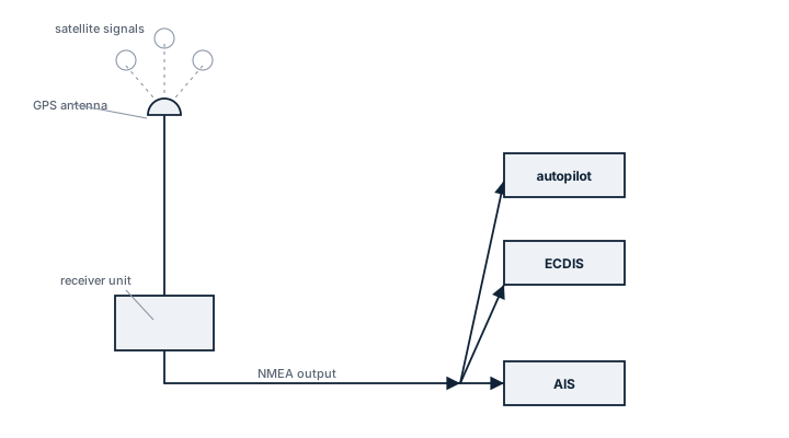
GPS receiver signal path
A masthead GPS antenna receives satellite signals and feeds a receiver unit, which distributes an NMEA position output to the ECDIS, autopilot and AIS.

Main components

Antenna

A dome-mounted active antenna with integral low-noise amplifier, positioned with a clear sky view away from radar scanners and funnel exhaust, which otherwise degrade signal-to-noise ratio.

Receiver / processing unit

Tracks 12 to 30+ satellite channels simultaneously, computes a weighted position solution, and applies differential corrections where available (SBAS such as EGNOS or WAAS, or a local DGPS beacon feed).

Output interfaces

NMEA 0183 or NMEA 2000 serial output feeding ECDIS, AIS, VDR and autopilot in parallel; many bridges wire two receivers into a changeover or voting arrangement so a single antenna fault does not blind every downstream system at once.

Selection criteria

  • Number of tracked constellations and channels -- more channels shorten re-acquisition time after a mast shadow or heavy roll.
  • Update rate, typically 1 Hz for standard navigation, higher for dynamic positioning feeds.
  • Differential correction support (SBAS, RTK) where the trade requires metre-level or sub-metre accuracy, for example dredging or offshore support work.
  • Output protocol compatibility with the existing ECDIS and VDR interface list.

Regulations and class

SOLAS Chapter V requires vessels to carry a receiver for a global navigation satellite system, or terrestrial radio navigation system, appropriate to the voyage, and to maintain a means of determining position that does not depend solely on one GNSS. Class societies survey the installation as part of the navigation equipment audit rather than as a standalone item, checking that the antenna position and cabling match the approved drawing and that backup arrangements are functional.

Typical faults

  • Antenna cable corrosion at the deck gland, causing intermittent signal loss that looks like a satellite outage rather than a wiring fault.
  • Loss of differential correction when the vessel moves out of SBAS or beacon coverage, degrading accuracy without triggering an alarm on older receivers.
  • Multipath error near steel superstructure or containers, producing a stable but wrong fix that the receiver reports with high confidence.
  • Firmware not updated for GPS week-number rollover, which can jump the reported date and confuse logging systems.

What to look for in a supplier

  • Type approval certificate matching the flag state and class society of the vessel, not just a generic marine label.
  • Documented output protocol list so integration with the existing ECDIS and AIS does not need a separate converter.
  • Availability of spares and firmware updates well beyond the initial warranty period, given typical fit life of ten years or more.

Two receivers from the same manufacturer and the same antenna run are still a single point of failure if they share a mast position and a power supply -- route the second antenna and cable separately if the redundancy is meant to mean anything during a storm or a mast strike.

10 manufacturers · 84 models

Furuno

19
GP-170D unverified
Channels
72
Waas egnos
ja
IMO Compliant
ja
Common Failures & Inspection Points
  • Sensor or transmitter failure caused by electronics, RF, antenna or transducer faults, noticed as missing or degraded navigation data
  • External sensor-input failure caused by GNSS, heading, speed or network faults, noticed as alarms, frozen data or misaligned overlays
  • Display/processor failure caused by power, cooling, storage or software faults, noticed as blank screen, rebooting or unavailable functions
  • Antenna/transducer/cable damage caused by weather, water ingress, fouling or impact, noticed as weak, intermittent or implausible signals
  • Incorrect configuration or calibration caused by maintenance or operator error, noticed as persistent disagreement with independent references
Service: Verify the equipment against an independent navigation reference where practicable, inspect antennas/transducers, cables and power supplies, and confirm required sensor inputs and alarms. Check data distribution to dependent bridge equipment and review calibration, chart or configuration status appropriate to the device. Use vessel procedures and manufacturer tests for acceptance.
Spare Parts: Carry fuses, connectors, selected power-supply and cooling parts, interface converters and manufacturer-recommended display/processor or sensor spares. Hull-mounted sensor replacement should be planned around the actual access arrangement.
Use Cases: Used on bridge navigation systems of merchant, passenger, offshore and specialist vessels for position, heading, speed, depth, radar target information or electronic chart navigation.
GP-150D unverified
Channels
72
Waas egnos
ja
IMO Compliant
ja
Common Failures & Inspection Points
  • Sensor or transmitter failure caused by electronics, RF, antenna or transducer faults, noticed as missing or degraded navigation data
  • External sensor-input failure caused by GNSS, heading, speed or network faults, noticed as alarms, frozen data or misaligned overlays
  • Display/processor failure caused by power, cooling, storage or software faults, noticed as blank screen, rebooting or unavailable functions
  • Antenna/transducer/cable damage caused by weather, water ingress, fouling or impact, noticed as weak, intermittent or implausible signals
  • Incorrect configuration or calibration caused by maintenance or operator error, noticed as persistent disagreement with independent references
Service: Verify the equipment against an independent navigation reference where practicable, inspect antennas/transducers, cables and power supplies, and confirm required sensor inputs and alarms. Check data distribution to dependent bridge equipment and review calibration, chart or configuration status appropriate to the device. Use vessel procedures and manufacturer tests for acceptance.
Spare Parts: Carry fuses, connectors, selected power-supply and cooling parts, interface converters and manufacturer-recommended display/processor or sensor spares. Hull-mounted sensor replacement should be planned around the actual access arrangement.
Use Cases: Used on bridge navigation systems of merchant, passenger, offshore and specialist vessels for position, heading, speed, depth, radar target information or electronic chart navigation.
GP-33 unverified
Channels
72
Waas egnos
ja
IMO Compliant
ja
Common Failures & Inspection Points
  • Sensor or transmitter failure caused by electronics, RF, antenna or transducer faults, noticed as missing or degraded navigation data
  • External sensor-input failure caused by GNSS, heading, speed or network faults, noticed as alarms, frozen data or misaligned overlays
  • Display/processor failure caused by power, cooling, storage or software faults, noticed as blank screen, rebooting or unavailable functions
  • Antenna/transducer/cable damage caused by weather, water ingress, fouling or impact, noticed as weak, intermittent or implausible signals
  • Incorrect configuration or calibration caused by maintenance or operator error, noticed as persistent disagreement with independent references
Service: Verify the equipment against an independent navigation reference where practicable, inspect antennas/transducers, cables and power supplies, and confirm required sensor inputs and alarms. Check data distribution to dependent bridge equipment and review calibration, chart or configuration status appropriate to the device. Use vessel procedures and manufacturer tests for acceptance.
Spare Parts: Carry fuses, connectors, selected power-supply and cooling parts, interface converters and manufacturer-recommended display/processor or sensor spares. Hull-mounted sensor replacement should be planned around the actual access arrangement.
Use Cases: Used on bridge navigation systems of merchant, passenger, offshore and specialist vessels for position, heading, speed, depth, radar target information or electronic chart navigation.
GP-32 unverified
Channels
12
Waas egnos
ja
IMO Compliant
ja
Common Failures & Inspection Points
  • Sensor or transmitter failure caused by electronics, RF, antenna or transducer faults, noticed as missing or degraded navigation data
  • External sensor-input failure caused by GNSS, heading, speed or network faults, noticed as alarms, frozen data or misaligned overlays
  • Display/processor failure caused by power, cooling, storage or software faults, noticed as blank screen, rebooting or unavailable functions
  • Antenna/transducer/cable damage caused by weather, water ingress, fouling or impact, noticed as weak, intermittent or implausible signals
  • Incorrect configuration or calibration caused by maintenance or operator error, noticed as persistent disagreement with independent references
Service: Verify the equipment against an independent navigation reference where practicable, inspect antennas/transducers, cables and power supplies, and confirm required sensor inputs and alarms. Check data distribution to dependent bridge equipment and review calibration, chart or configuration status appropriate to the device. Use vessel procedures and manufacturer tests for acceptance.
Spare Parts: Carry fuses, connectors, selected power-supply and cooling parts, interface converters and manufacturer-recommended display/processor or sensor spares. Hull-mounted sensor replacement should be planned around the actual access arrangement.
Use Cases: Used on bridge navigation systems of merchant, passenger, offshore and specialist vessels for position, heading, speed, depth, radar target information or electronic chart navigation.
SC-50 unverified
Type
Satellite Compass
Heading accuracy deg
0.25
Gps glonass
ja
Common Failures & Inspection Points
  • Sensor or transmitter failure caused by electronics, RF, antenna or transducer faults, noticed as missing or degraded navigation data
  • External sensor-input failure caused by GNSS, heading, speed or network faults, noticed as alarms, frozen data or misaligned overlays
  • Display/processor failure caused by power, cooling, storage or software faults, noticed as blank screen, rebooting or unavailable functions
  • Antenna/transducer/cable damage caused by weather, water ingress, fouling or impact, noticed as weak, intermittent or implausible signals
  • Incorrect configuration or calibration caused by maintenance or operator error, noticed as persistent disagreement with independent references
Service: Verify the equipment against an independent navigation reference where practicable, inspect antennas/transducers, cables and power supplies, and confirm required sensor inputs and alarms. Check data distribution to dependent bridge equipment and review calibration, chart or configuration status appropriate to the device. Use vessel procedures and manufacturer tests for acceptance.
Spare Parts: Carry fuses, connectors, selected power-supply and cooling parts, interface converters and manufacturer-recommended display/processor or sensor spares. Hull-mounted sensor replacement should be planned around the actual access arrangement.
Use Cases: Used on bridge navigation systems of merchant, passenger, offshore and specialist vessels for position, heading, speed, depth, radar target information or electronic chart navigation.
SC-130
Class
Satellite compass / THD
GNSS Bands
GPS L1/L2, GLONASS, Galileo, QZSS
Heading Accuracy (RMS)
0.4 deg
Roll/Pitch Accuracy
1.0 deg
Outputs
Heading, ROT, pitch/roll, heave, position
Type Approval
IMO MSC.116(73), IEC 60945, IEC 61162
Common Failures & Inspection Points
  • Sensor or transmitter failure caused by electronics, RF, antenna or transducer faults, noticed as missing or degraded navigation data
  • External sensor-input failure caused by GNSS, heading, speed or network faults, noticed as alarms, frozen data or misaligned overlays
  • Display/processor failure caused by power, cooling, storage or software faults, noticed as blank screen, rebooting or unavailable functions
  • Antenna/transducer/cable damage caused by weather, water ingress, fouling or impact, noticed as weak, intermittent or implausible signals
  • Incorrect configuration or calibration caused by maintenance or operator error, noticed as persistent disagreement with independent references
Service: Verify the equipment against an independent navigation reference where practicable, inspect antennas/transducers, cables and power supplies, and confirm required sensor inputs and alarms. Check data distribution to dependent bridge equipment and review calibration, chart or configuration status appropriate to the device. Use vessel procedures and manufacturer tests for acceptance.
Spare Parts: Carry fuses, connectors, selected power-supply and cooling parts, interface converters and manufacturer-recommended display/processor or sensor spares. Hull-mounted sensor replacement should be planned around the actual access arrangement.
Use Cases: Used on bridge navigation systems of merchant, passenger, offshore and specialist vessels for position, heading, speed, depth, radar target information or electronic chart navigation.
SC-33
Antenna Count
2
Heading Accuracy
0.5 deg RMS
Outputs
NMEA 0183, NMEA 2000
Type Approval
IEC 60945, IMO MSC.116(73)
Common Failures & Inspection Points
  • Sensor or transmitter failure caused by electronics, RF, antenna or transducer faults, noticed as missing or degraded navigation data
  • External sensor-input failure caused by GNSS, heading, speed or network faults, noticed as alarms, frozen data or misaligned overlays
  • Display/processor failure caused by power, cooling, storage or software faults, noticed as blank screen, rebooting or unavailable functions
  • Antenna/transducer/cable damage caused by weather, water ingress, fouling or impact, noticed as weak, intermittent or implausible signals
  • Incorrect configuration or calibration caused by maintenance or operator error, noticed as persistent disagreement with independent references
Service: Verify the equipment against an independent navigation reference where practicable, inspect antennas/transducers, cables and power supplies, and confirm required sensor inputs and alarms. Check data distribution to dependent bridge equipment and review calibration, chart or configuration status appropriate to the device. Use vessel procedures and manufacturer tests for acceptance.
Spare Parts: Carry fuses, connectors, selected power-supply and cooling parts, interface converters and manufacturer-recommended display/processor or sensor spares. Hull-mounted sensor replacement should be planned around the actual access arrangement.
Use Cases: Used on bridge navigation systems of merchant, passenger, offshore and specialist vessels for position, heading, speed, depth, radar target information or electronic chart navigation.
GP-170 NAV unverified
Waas egnos
ja
Common Failures & Inspection Points
  • Antenna or sensor fault caused by damage, water ingress or obstruction, resulting in loss or degradation of navigation data
  • Power-supply failure caused by breaker, converter or wiring problems, resulting in loss of indication
  • Processor or display fault caused by electronics or software problems, resulting in frozen, blank or erroneous output
  • Interface or network failure caused by cabling or configuration faults, resulting in missing data at connected bridge equipment
  • Calibration or configuration error caused by incorrect setup, resulting in persistent disagreement with independent navigation references
Service: Compare the indicated value with independent references and investigate persistent disagreement rather than applying unrecorded corrections. Inspect sensors, antennas, cabling, power supplies, repeaters and network interfaces applicable to the installed equipment. Verify alarms and data outputs to radar, ECDIS, autopilot and voyage-data systems where connected. Keep calibration, deviation or configuration records current as appropriate to the sensor type. Protect exposed sensors from paint, deposits and water ingress. Refer to manufacturer and bridge-equipment documentation for exact test, calibration and alignment procedures.
Spare Parts: Keep fuses, lamps or display consumables, selected power-supply and interface modules, cables or connectors and manufacturer-recommended sensor service parts. Replacement core sensors or processors must remain compatible with the approved bridge installation. Preserve calibration and configuration data when changing equipment.
Use Cases: Heading, position or speed information for navigation, collision avoidance, autopilot, ECDIS and other bridge systems on merchant and offshore vessels.
GP-170 FISH unverified
Waas egnos
ja
Common Failures & Inspection Points
  • Antenna or sensor fault caused by damage, water ingress or obstruction, resulting in loss or degradation of navigation data
  • Power-supply failure caused by breaker, converter or wiring problems, resulting in loss of indication
  • Processor or display fault caused by electronics or software problems, resulting in frozen, blank or erroneous output
  • Interface or network failure caused by cabling or configuration faults, resulting in missing data at connected bridge equipment
  • Calibration or configuration error caused by incorrect setup, resulting in persistent disagreement with independent navigation references
Service: Compare the indicated value with independent references and investigate persistent disagreement rather than applying unrecorded corrections. Inspect sensors, antennas, cabling, power supplies, repeaters and network interfaces applicable to the installed equipment. Verify alarms and data outputs to radar, ECDIS, autopilot and voyage-data systems where connected. Keep calibration, deviation or configuration records current as appropriate to the sensor type. Protect exposed sensors from paint, deposits and water ingress. Refer to manufacturer and bridge-equipment documentation for exact test, calibration and alignment procedures.
Spare Parts: Keep fuses, lamps or display consumables, selected power-supply and interface modules, cables or connectors and manufacturer-recommended sensor service parts. Replacement core sensors or processors must remain compatible with the approved bridge installation. Preserve calibration and configuration data when changing equipment.
Use Cases: Heading, position or speed information for navigation, collision avoidance, autopilot, ECDIS and other bridge systems on merchant and offshore vessels.
GP-39 WAAS unverified
Waas egnos
ja
Common Failures & Inspection Points
  • Antenna or sensor fault caused by damage, water ingress or obstruction, resulting in loss or degradation of navigation data
  • Power-supply failure caused by breaker, converter or wiring problems, resulting in loss of indication
  • Processor or display fault caused by electronics or software problems, resulting in frozen, blank or erroneous output
  • Interface or network failure caused by cabling or configuration faults, resulting in missing data at connected bridge equipment
  • Calibration or configuration error caused by incorrect setup, resulting in persistent disagreement with independent navigation references
Service: Compare the indicated value with independent references and investigate persistent disagreement rather than applying unrecorded corrections. Inspect sensors, antennas, cabling, power supplies, repeaters and network interfaces applicable to the installed equipment. Verify alarms and data outputs to radar, ECDIS, autopilot and voyage-data systems where connected. Keep calibration, deviation or configuration records current as appropriate to the sensor type. Protect exposed sensors from paint, deposits and water ingress. Refer to manufacturer and bridge-equipment documentation for exact test, calibration and alignment procedures.
Spare Parts: Keep fuses, lamps or display consumables, selected power-supply and interface modules, cables or connectors and manufacturer-recommended sensor service parts. Replacement core sensors or processors must remain compatible with the approved bridge installation. Preserve calibration and configuration data when changing equipment.
Use Cases: Heading, position or speed information for navigation, collision avoidance, autopilot, ECDIS and other bridge systems on merchant and offshore vessels.
GP-33 SBAS unverified
Waas egnos
ja
Common Failures & Inspection Points
  • Antenna or sensor fault caused by damage, water ingress or obstruction, resulting in loss or degradation of navigation data
  • Power-supply failure caused by breaker, converter or wiring problems, resulting in loss of indication
  • Processor or display fault caused by electronics or software problems, resulting in frozen, blank or erroneous output
  • Interface or network failure caused by cabling or configuration faults, resulting in missing data at connected bridge equipment
  • Calibration or configuration error caused by incorrect setup, resulting in persistent disagreement with independent navigation references
Service: Compare the indicated value with independent references and investigate persistent disagreement rather than applying unrecorded corrections. Inspect sensors, antennas, cabling, power supplies, repeaters and network interfaces applicable to the installed equipment. Verify alarms and data outputs to radar, ECDIS, autopilot and voyage-data systems where connected. Keep calibration, deviation or configuration records current as appropriate to the sensor type. Protect exposed sensors from paint, deposits and water ingress. Refer to manufacturer and bridge-equipment documentation for exact test, calibration and alignment procedures.
Spare Parts: Keep fuses, lamps or display consumables, selected power-supply and interface modules, cables or connectors and manufacturer-recommended sensor service parts. Replacement core sensors or processors must remain compatible with the approved bridge installation. Preserve calibration and configuration data when changing equipment.
Use Cases: Heading, position or speed information for navigation, collision avoidance, autopilot, ECDIS and other bridge systems on merchant and offshore vessels.
GP-1871F unverified
Waas egnos
ja
Common Failures & Inspection Points
  • Loss of electrical, hydraulic, pneumatic, or other service supply caused by a tripped protection device, leakage, blockage, or upstream fault results in failed starting or loss of function
  • Mechanical wear, corrosion, fouling, or contamination of moving and wetted parts causes increased noise, leakage, sticking, vibration, or reduced performance
  • Seal, gasket, hose, cable, or connection deterioration from age, heat, vibration, or environmental exposure produces visible leakage, intermittent signals, or loss of pressure
  • Sensor, switch, actuator, relay, or control-system faults can cause incorrect indication, nuisance alarms, failed automatic sequences, or loss of remote control
  • Incorrect adjustment, assembly, or maintenance can lead to unstable operation, recurrent alarms, or performance that differs from the vessel's normal baseline
Service: Inspect the unit for leakage, corrosion, contamination, loose connections, abnormal noise or vibration, condition of guards and mountings, service supplies, controls, alarms, and functional performance. Use the vessel maintenance history to identify deterioration trends and refer to the manufacturer documentation for exact settings, tolerances, test values, and overhaul criteria.
Spare Parts: Keep the manufacturer-recommended seals and gaskets, filters where fitted, fuses or protection items, common sensors and switches, and critical actuator, control, or wear components appropriate to the installed configuration. Exact part numbers and quantities must come from the manufacturer spare-parts documentation.
Use Cases: Used on vessel types fitted with position & heading equipment, including merchant, offshore, passenger, fishing, or workboat installations where this specific gps receiver duty is required.
GP-1971F unverified
Waas egnos
ja
Common Failures & Inspection Points
  • Loss of electrical, hydraulic, pneumatic, or other service supply caused by a tripped protection device, leakage, blockage, or upstream fault results in failed starting or loss of function
  • Mechanical wear, corrosion, fouling, or contamination of moving and wetted parts causes increased noise, leakage, sticking, vibration, or reduced performance
  • Seal, gasket, hose, cable, or connection deterioration from age, heat, vibration, or environmental exposure produces visible leakage, intermittent signals, or loss of pressure
  • Sensor, switch, actuator, relay, or control-system faults can cause incorrect indication, nuisance alarms, failed automatic sequences, or loss of remote control
  • Incorrect adjustment, assembly, or maintenance can lead to unstable operation, recurrent alarms, or performance that differs from the vessel's normal baseline
Service: Inspect the unit for leakage, corrosion, contamination, loose connections, abnormal noise or vibration, condition of guards and mountings, service supplies, controls, alarms, and functional performance. Use the vessel maintenance history to identify deterioration trends and refer to the manufacturer documentation for exact settings, tolerances, test values, and overhaul criteria.
Spare Parts: Keep the manufacturer-recommended seals and gaskets, filters where fitted, fuses or protection items, common sensors and switches, and critical actuator, control, or wear components appropriate to the installed configuration. Exact part numbers and quantities must come from the manufacturer spare-parts documentation.
Use Cases: Used on vessel types fitted with position & heading equipment, including merchant, offshore, passenger, fishing, or workboat installations where this specific gps receiver duty is required.
GP-1870F unverified
Waas egnos
ja
Common Failures & Inspection Points
  • Loss of electrical, hydraulic, pneumatic, or other service supply caused by a tripped protection device, leakage, blockage, or upstream fault results in failed starting or loss of function
  • Mechanical wear, corrosion, fouling, or contamination of moving and wetted parts causes increased noise, leakage, sticking, vibration, or reduced performance
  • Seal, gasket, hose, cable, or connection deterioration from age, heat, vibration, or environmental exposure produces visible leakage, intermittent signals, or loss of pressure
  • Sensor, switch, actuator, relay, or control-system faults can cause incorrect indication, nuisance alarms, failed automatic sequences, or loss of remote control
  • Incorrect adjustment, assembly, or maintenance can lead to unstable operation, recurrent alarms, or performance that differs from the vessel's normal baseline
Service: Inspect the unit for leakage, corrosion, contamination, loose connections, abnormal noise or vibration, condition of guards and mountings, service supplies, controls, alarms, and functional performance. Use the vessel maintenance history to identify deterioration trends and refer to the manufacturer documentation for exact settings, tolerances, test values, and overhaul criteria.
Spare Parts: Keep the manufacturer-recommended seals and gaskets, filters where fitted, fuses or protection items, common sensors and switches, and critical actuator, control, or wear components appropriate to the installed configuration. Exact part numbers and quantities must come from the manufacturer spare-parts documentation.
Use Cases: Used on vessel types fitted with position & heading equipment, including merchant, offshore, passenger, fishing, or workboat installations where this specific gps receiver duty is required.
GP-170 GLONASS unverified
Multi gnss
ja
Common Failures & Inspection Points
  • Loss of sensor input or damaged cabling causes missing, frozen or implausible navigation data
  • Antenna, transducer or scanner faults reduce detection or measurement performance and generate equipment alarms
  • Power-supply or cooling faults cause resets, blank displays or complete loss of function
  • Configuration or interface faults cause disagreement between systems or missing data on connected equipment
  • Display, control or processing faults cause unstable operation, error messages or inability to select required functions
Service: Check power supplies, data interfaces, alarms, sensor health and agreement with independent navigation information where practical. Inspect external antennas, scanners or transducers as applicable and review fault logs and self-test results. Verify required backups, records and bridge procedures; exact calibration tolerances and test methods must follow manufacturer and statutory documentation.
Spare Parts: Typical spares include approved fuses, cooling fans, display or keypad parts where supported, interface modules, data cables and selected sensor or antenna components according to the vessel's critical-spares policy.
Use Cases: Used on commercial and offshore vessels for navigation, collision avoidance, route monitoring, heading control and voyage recording according to the specific equipment type.
GP-170 BeiDou unverified
Multi gnss
ja
Common Failures & Inspection Points
  • Antenna, feeder or connector damage causes weak satellite reception, position loss or frequent alarms
  • Power-supply failure causes receiver resets or complete loss of position output
  • Incorrect configuration or datum settings cause position discrepancies or incompatible outputs
  • Serial, network or NMEA interface faults remove position from ECDIS, AIS, GMDSS or other consumers
  • Receiver or firmware faults cause intermittent fixes, frozen position or integrity warnings
Service: Inspect antenna, feeder, connectors, power supply and data interfaces. Compare position and time with independent sources and verify distribution to bridge consumers. Review integrity or satellite alarms. Configuration and firmware changes should follow approved manufacturer procedures.
Spare Parts: Carry fuses, antenna connectors, approved power-supply parts, data-interface cables and a compatible replacement antenna or receiver module where vessel policy requires it.
Use Cases: Primary position and timing source for navigation, AIS, GMDSS and bridge integration.
GP-170 Galileo unverified
Multi gnss
ja
Common Failures & Inspection Points
  • Loss of sensor input or damaged cabling causes missing, frozen or implausible navigation data
  • Antenna, transducer or scanner faults reduce detection or measurement performance and generate equipment alarms
  • Power-supply or cooling faults cause resets, blank displays or complete loss of function
  • Configuration or interface faults cause disagreement between systems or missing data on connected equipment
  • Display, control or processing faults cause unstable operation, error messages or inability to select required functions
Service: Check power supplies, data interfaces, alarms, sensor health and agreement with independent navigation information where practical. Inspect external antennas, scanners or transducers as applicable and review fault logs and self-test results. Verify required backups, records and bridge procedures; exact calibration tolerances and test methods must follow manufacturer and statutory documentation.
Spare Parts: Typical spares include approved fuses, cooling fans, display or keypad parts where supported, interface modules, data cables and selected sensor or antenna components according to the vessel's critical-spares policy.
Use Cases: Used on commercial and offshore vessels for navigation, collision avoidance, route monitoring, heading control and voyage recording according to the specific equipment type.
GP-170 Multi-GNSS unverified
Multi gnss
ja
Common Failures & Inspection Points
  • Sensor, antenna or transducer fouling, damage or misalignment causes unstable, missing or inaccurate data
  • Power-supply or processor faults cause resets, blank displays or complete loss of indication
  • Cable, connector or network faults cause intermittent data or loss of outputs to other bridge systems
  • Incorrect configuration or calibration causes persistent disagreement with independent references
  • Display or software faults cause frozen values, alarms or unavailable functions
Service: Inspect sensors, antennas, transducers, cabling, power supplies, displays and data interfaces. Compare information with independent references and review alarm history. Verify distribution to dependent bridge systems. Refer to the manufacturer documentation for the exact figure for calibration, alignment and performance criteria.
Spare Parts: Carry fuses, interface cables, approved power supplies, sensor or antenna parts and supported display or processor modules.
Use Cases: Navigation, pilotage, collision avoidance and bridge-system integration.
GP-39 Multi-GNSS unverified
Multi gnss
ja
Common Failures & Inspection Points
  • Sensor or antenna fault caused by fouling, damage, wear or water ingress, resulting in loss, weak response or degraded navigation data
  • Power-supply failure caused by breaker, converter or wiring problems, resulting in loss of indication
  • Processor or display fault caused by electronics or software problems, resulting in frozen, blank or erroneous output
  • Interface or network failure caused by cabling or configuration faults, resulting in missing data at connected bridge equipment
  • Calibration, alignment or configuration error caused by incorrect setup or maintenance, resulting in persistent disagreement with independent navigation references
Service: Compare the indicated value with independent references and investigate persistent disagreement rather than applying unrecorded corrections. Inspect sensors, antennas, transducers, cabling, power supplies, repeaters and network interfaces applicable to the installed equipment. Verify alarms and data outputs to radar, ECDIS, autopilot and voyage-data systems where connected. Keep calibration, deviation or configuration records current as appropriate to the sensor type. Protect exposed sensors and transducers from paint, deposits and water ingress. Refer to manufacturer and bridge-equipment documentation for exact test, calibration and alignment procedures.
Spare Parts: Keep fuses, lamps or display consumables, selected power-supply and interface modules, cables or connectors and manufacturer-recommended sensor service parts. Replacement core sensors, antennas or processors must remain compatible with the approved bridge installation. Preserve calibration and configuration data when changing equipment.
Use Cases: Bridge navigation and sensor input for collision avoidance, route monitoring, steering, depth awareness and other shipboard navigation functions according to the equipment category.

Kongsberg Maritime

13
Seatex Seapath 130 unverified
Multi constellation
ja
Heading accuracy deg
0.1
Common Failures & Inspection Points
  • Antenna/sensor or cable fault, typically indicated by loss of position/heading/speed data or sensor alarm
  • Power-supply failure, typically indicated by blank display or unavailable output
  • Signal interference, blockage or poor sensor environment, typically indicated by unstable data, loss of fix or erratic readings
  • Interface/network configuration fault, typically indicated by downstream equipment shows missing or invalid data
  • Calibration/alignment drift where applicable, typically indicated by systematic heading/speed error or discrepancy with independent references
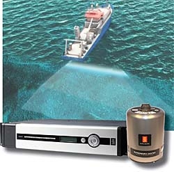
Service: Check sensor health, antenna/mounting condition, power, interfaces, alarms and comparison with independent references; calibration/alignment should follow approved procedures and manufacturer data.
Spare Parts: Carry critical power supplies, interface converters, antenna/cable components, display controls and sensor-specific service spares.
Use Cases: Used on all navigating vessels to supply position, heading and speed information to bridge, steering and recording systems. This entry applies specifically to the GPS Receiver variant identified as Kongsberg Maritime Seatex Seapath 130.
Kongsberg Maritime Seatex Seapath 330+
Seatex Seapath 330+ unverified
Multi constellation
ja
Heading accuracy deg
0.1
Common Failures & Inspection Points
  • Antenna/sensor or cable fault, typically indicated by loss of position/heading/speed data or sensor alarm
  • Power-supply failure, typically indicated by blank display or unavailable output
  • Signal interference, blockage or poor sensor environment, typically indicated by unstable data, loss of fix or erratic readings
  • Interface/network configuration fault, typically indicated by downstream equipment shows missing or invalid data
  • Calibration/alignment drift where applicable, typically indicated by systematic heading/speed error or discrepancy with independent references
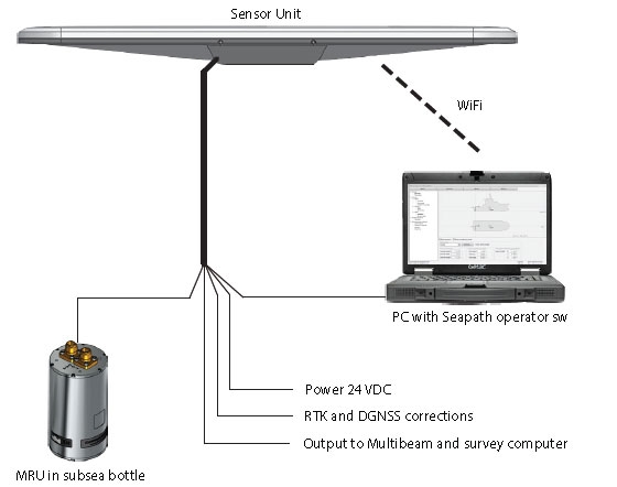
Service: Check sensor health, antenna/mounting condition, power, interfaces, alarms and comparison with independent references; calibration/alignment should follow approved procedures and manufacturer data.
Spare Parts: Carry critical power supplies, interface converters, antenna/cable components, display controls and sensor-specific service spares.
Use Cases: Used on all navigating vessels to supply position, heading and speed information to bridge, steering and recording systems. This entry applies specifically to the GPS Receiver variant identified as Kongsberg Maritime Seatex Seapath 330+.
Kongsberg Maritime Seatex Seapath 380
Seatex Seapath 380 unverified
Multi constellation
ja
Heading accuracy deg
0.02
Common Failures & Inspection Points
  • Antenna/sensor or cable fault, typically indicated by loss of position/heading/speed data or sensor alarm
  • Power-supply failure, typically indicated by blank display or unavailable output
  • Signal interference, blockage or poor sensor environment, typically indicated by unstable data, loss of fix or erratic readings
  • Interface/network configuration fault, typically indicated by downstream equipment shows missing or invalid data
  • Calibration/alignment drift where applicable, typically indicated by systematic heading/speed error or discrepancy with independent references
Service: Check sensor health, antenna/mounting condition, power, interfaces, alarms and comparison with independent references; calibration/alignment should follow approved procedures and manufacturer data.
Spare Parts: Carry critical power supplies, interface converters, antenna/cable components, display controls and sensor-specific service spares.
Use Cases: Used on all navigating vessels to supply position, heading and speed information to bridge, steering and recording systems. This entry applies specifically to the GPS Receiver variant identified as Kongsberg Maritime Seatex Seapath 380.
Seatex MRU5+ unverified
Multi constellation
ja
Heading accuracy deg
0.1
Common Failures & Inspection Points
  • Sensor drift, damage or loss of reference caused by ageing, magnetic influence, antenna issues or internal faults can produce unstable or incorrect heading or position information
  • Control or interface failure caused by electronics, cabling or network faults can create steering alarms, rejected inputs or loss of automatic control
  • Power-supply interruption caused by loose connections, protection trips or internal failure can result in resets or total loss of indication
  • Incorrect calibration or configuration after maintenance can show as persistent offset, poor course keeping or disagreement with independent references
  • Mechanical wear in connected steering components where applicable can cause slow response, hunting, leakage or increased steering error
Service: Compare indications with independent references, inspect sensors and cable routes, verify power supplies and alarms, and test changeover or backup arrangements where fitted. For heading-control equipment, examine the connected steering feedback and response as well as the bridge controller. Refer to manufacturer documentation for exact calibration and acceptance values.
Spare Parts: Useful spares include maker-approved fuses, interface modules, power-supply parts, display or control modules, connectors and sensor accessories appropriate to the installed system.
Use Cases: Merchant, passenger, offshore and specialist vessels requiring heading, position, speed or automatic steering information at the bridge.
Kongsberg Maritime DPS-116
DPS-116 unverified
Multi constellation
ja
Heading accuracy deg
0.1
Common Failures & Inspection Points
  • Loss of electrical, hydraulic, pneumatic, or other service supply caused by a tripped protection device, leakage, blockage, or upstream fault results in failed starting or loss of function
  • Mechanical wear, corrosion, fouling, or contamination of moving and wetted parts causes increased noise, leakage, sticking, vibration, or reduced performance
  • Seal, gasket, hose, cable, or connection deterioration from age, heat, vibration, or environmental exposure produces visible leakage, intermittent signals, or loss of pressure
  • Sensor, switch, actuator, relay, or control-system faults can cause incorrect indication, nuisance alarms, failed automatic sequences, or loss of remote control
  • Incorrect adjustment, assembly, or maintenance can lead to unstable operation, recurrent alarms, or performance that differs from the vessel's normal baseline
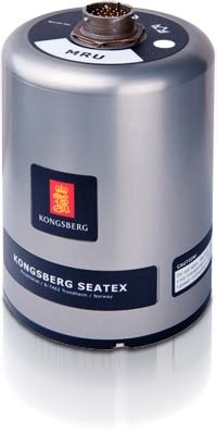
Service: Inspect the unit for leakage, corrosion, contamination, loose connections, abnormal noise or vibration, condition of guards and mountings, service supplies, controls, alarms, and functional performance. Use the vessel maintenance history to identify deterioration trends and refer to the manufacturer documentation for exact settings, tolerances, test values, and overhaul criteria.
Spare Parts: Keep the manufacturer-recommended seals and gaskets, filters where fitted, fuses or protection items, common sensors and switches, and critical actuator, control, or wear components appropriate to the installed configuration. Exact part numbers and quantities must come from the manufacturer spare-parts documentation.
Use Cases: Used on vessel types fitted with position & heading equipment, including merchant, offshore, passenger, fishing, or workboat installations where this specific gps receiver duty is required.
Kongsberg Maritime Seatex DPS-200
Seatex DPS-200 unverified
Multi gnss
ja
Seatex DPS-232 unverified
Multi gnss
ja
Common Failures & Inspection Points
  • Sensor contamination, mechanical damage, ageing, or environmental exposure causes drifting, unstable, or missing measurements
  • Power-supply, fuse, or internal electronic faults cause loss of indication, rebooting, or sensor-offline alarms
  • Cable, connector, network, or interface faults produce intermittent data or loss of information at repeaters and connected systems
  • Incorrect alignment, calibration, configuration, or reference input causes a consistent offset or implausible readings
  • Display, repeater, processor, or software faults can cause frozen values, failed alarms, or disagreement between indications
Service: Check sensor condition and mounting, power supply, cabling, connectors, reference inputs, repeaters, interfaces, alarm history, and comparison with independent indications where practical. Calibration, alignment, and exact accuracy limits must follow manufacturer and statutory documentation.
Spare Parts: Carry approved fuses, connectors, interface modules, display or control items, sensor service parts, and model-specific power-supply components recommended by the manufacturer.
Use Cases: Used on merchant, passenger, offshore, fishing, research, and workboat vessels to support navigation, heading, speed, depth, position, or weather awareness.
Seatex Seapath 130+ unverified
Multi gnss
ja
Common Failures & Inspection Points
  • Antenna/sensor or cable fault, typically indicated by loss of position/heading/speed data or sensor alarm
  • Power-supply failure, typically indicated by blank display or unavailable output
  • Signal interference, blockage or poor sensor environment, typically indicated by unstable data, loss of fix or erratic readings
  • Interface/network configuration fault, typically indicated by downstream equipment shows missing or invalid data
  • Calibration/alignment drift where applicable, typically indicated by systematic heading/speed error or discrepancy with independent references
Service: Check sensor health, antenna/mounting condition, power, interfaces, alarms and comparison with independent references; calibration/alignment should follow approved procedures and manufacturer data.
Spare Parts: Carry critical power supplies, interface converters, antenna/cable components, display controls and sensor-specific service spares.
Use Cases: Used on all navigating vessels to supply position, heading and speed information to bridge, steering and recording systems. This entry applies specifically to the GPS Receiver variant identified as Kongsberg Maritime Seatex Seapath 130+.
Kongsberg Maritime Seatex Seapath 230
Seatex Seapath 230 unverified
Multi gnss
ja
Common Failures & Inspection Points
  • Antenna/sensor or cable fault, typically indicated by loss of position/heading/speed data or sensor alarm
  • Power-supply failure, typically indicated by blank display or unavailable output
  • Signal interference, blockage or poor sensor environment, typically indicated by unstable data, loss of fix or erratic readings
  • Interface/network configuration fault, typically indicated by downstream equipment shows missing or invalid data
  • Calibration/alignment drift where applicable, typically indicated by systematic heading/speed error or discrepancy with independent references
Service: Check sensor health, antenna/mounting condition, power, interfaces, alarms and comparison with independent references; calibration/alignment should follow approved procedures and manufacturer data.
Spare Parts: Carry critical power supplies, interface converters, antenna/cable components, display controls and sensor-specific service spares.
Use Cases: Used on all navigating vessels to supply position, heading and speed information to bridge, steering and recording systems. This entry applies specifically to the GPS Receiver variant identified as Kongsberg Maritime Seatex Seapath 230.
Kongsberg Maritime Seatex Seapath 330
Seatex Seapath 330 unverified
Multi gnss
ja
Common Failures & Inspection Points
  • Antenna/sensor or cable fault, typically indicated by loss of position/heading/speed data or sensor alarm
  • Power-supply failure, typically indicated by blank display or unavailable output
  • Signal interference, blockage or poor sensor environment, typically indicated by unstable data, loss of fix or erratic readings
  • Interface/network configuration fault, typically indicated by downstream equipment shows missing or invalid data
  • Calibration/alignment drift where applicable, typically indicated by systematic heading/speed error or discrepancy with independent references
Service: Check sensor health, antenna/mounting condition, power, interfaces, alarms and comparison with independent references; calibration/alignment should follow approved procedures and manufacturer data.
Spare Parts: Carry critical power supplies, interface converters, antenna/cable components, display controls and sensor-specific service spares.
Use Cases: Used on all navigating vessels to supply position, heading and speed information to bridge, steering and recording systems. This entry applies specifically to the GPS Receiver variant identified as Kongsberg Maritime Seatex Seapath 330.
Seatex Seapath 380+ unverified
IMO Compliant
ja
Common Failures & Inspection Points
  • Antenna/sensor or cable fault, typically indicated by loss of position/heading/speed data or sensor alarm
  • Power-supply failure, typically indicated by blank display or unavailable output
  • Signal interference, blockage or poor sensor environment, typically indicated by unstable data, loss of fix or erratic readings
  • Interface/network configuration fault, typically indicated by downstream equipment shows missing or invalid data
  • Calibration/alignment drift where applicable, typically indicated by systematic heading/speed error or discrepancy with independent references
Service: Check sensor health, antenna/mounting condition, power, interfaces, alarms and comparison with independent references; calibration/alignment should follow approved procedures and manufacturer data.
Spare Parts: Carry critical power supplies, interface converters, antenna/cable components, display controls and sensor-specific service spares.
Use Cases: Used on all navigating vessels to supply position, heading and speed information to bridge, steering and recording systems. This entry applies specifically to the GPS Receiver variant identified as Kongsberg Maritime Seatex Seapath 380+.
Seatex Seapath 430 unverified
IMO Compliant
ja
Common Failures & Inspection Points
  • Antenna/sensor or cable fault, typically indicated by loss of position/heading/speed data or sensor alarm
  • Power-supply failure, typically indicated by blank display or unavailable output
  • Signal interference, blockage or poor sensor environment, typically indicated by unstable data, loss of fix or erratic readings
  • Interface/network configuration fault, typically indicated by downstream equipment shows missing or invalid data
  • Calibration/alignment drift where applicable, typically indicated by systematic heading/speed error or discrepancy with independent references
Service: Check sensor health, antenna/mounting condition, power, interfaces, alarms and comparison with independent references; calibration/alignment should follow approved procedures and manufacturer data.
Spare Parts: Carry critical power supplies, interface converters, antenna/cable components, display controls and sensor-specific service spares.
Use Cases: Used on all navigating vessels to supply position, heading and speed information to bridge, steering and recording systems. This entry applies specifically to the GPS Receiver variant identified as Kongsberg Maritime Seatex Seapath 430.
Seatex DPS-300 unverified
IMO Compliant
ja
Common Failures & Inspection Points
  • Sensor contamination, mechanical damage, ageing, or environmental exposure causes drifting, unstable, or missing measurements
  • Power-supply, fuse, or internal electronic faults cause loss of indication, rebooting, or sensor-offline alarms
  • Cable, connector, network, or interface faults produce intermittent data or loss of information at repeaters and connected systems
  • Incorrect alignment, calibration, configuration, or reference input causes a consistent offset or implausible readings
  • Display, repeater, processor, or software faults can cause frozen values, failed alarms, or disagreement between indications
Service: Check sensor condition and mounting, power supply, cabling, connectors, reference inputs, repeaters, interfaces, alarm history, and comparison with independent indications where practical. Calibration, alignment, and exact accuracy limits must follow manufacturer and statutory documentation.
Spare Parts: Carry approved fuses, connectors, interface modules, display or control items, sensor service parts, and model-specific power-supply components recommended by the manufacturer.
Use Cases: Used on merchant, passenger, offshore, fishing, research, and workboat vessels to support navigation, heading, speed, depth, position, or weather awareness.

JRC (Japan Radio Co)

11
JLR-21 unverified
Dgps
ja
IMO Compliant
ja
Common Failures & Inspection Points
  • Loss of electrical, hydraulic, pneumatic, or other service supply caused by a tripped protection device, leakage, blockage, or upstream fault results in failed starting or loss of function
  • Mechanical wear, corrosion, fouling, or contamination of moving and wetted parts causes increased noise, leakage, sticking, vibration, or reduced performance
  • Seal, gasket, hose, cable, or connection deterioration from age, heat, vibration, or environmental exposure produces visible leakage, intermittent signals, or loss of pressure
  • Sensor, switch, actuator, relay, or control-system faults can cause incorrect indication, nuisance alarms, failed automatic sequences, or loss of remote control
  • Incorrect adjustment, assembly, or maintenance can lead to unstable operation, recurrent alarms, or performance that differs from the vessel's normal baseline
Service: Inspect the unit for leakage, corrosion, contamination, loose connections, abnormal noise or vibration, condition of guards and mountings, service supplies, controls, alarms, and functional performance. Use the vessel maintenance history to identify deterioration trends and refer to the manufacturer documentation for exact settings, tolerances, test values, and overhaul criteria.
Spare Parts: Keep the manufacturer-recommended seals and gaskets, filters where fitted, fuses or protection items, common sensors and switches, and critical actuator, control, or wear components appropriate to the installed configuration. Exact part numbers and quantities must come from the manufacturer spare-parts documentation.
Use Cases: Used on vessel types fitted with position & heading equipment, including merchant, offshore, passenger, fishing, or workboat installations where this specific gps receiver duty is required.
JLR-31 unverified
Dgps
ja
IMO Compliant
ja
Common Failures & Inspection Points
  • Loss of electrical, hydraulic, pneumatic, or other service supply caused by a tripped protection device, leakage, blockage, or upstream fault results in failed starting or loss of function
  • Mechanical wear, corrosion, fouling, or contamination of moving and wetted parts causes increased noise, leakage, sticking, vibration, or reduced performance
  • Seal, gasket, hose, cable, or connection deterioration from age, heat, vibration, or environmental exposure produces visible leakage, intermittent signals, or loss of pressure
  • Sensor, switch, actuator, relay, or control-system faults can cause incorrect indication, nuisance alarms, failed automatic sequences, or loss of remote control
  • Incorrect adjustment, assembly, or maintenance can lead to unstable operation, recurrent alarms, or performance that differs from the vessel's normal baseline
Service: Inspect the unit for leakage, corrosion, contamination, loose connections, abnormal noise or vibration, condition of guards and mountings, service supplies, controls, alarms, and functional performance. Use the vessel maintenance history to identify deterioration trends and refer to the manufacturer documentation for exact settings, tolerances, test values, and overhaul criteria.
Spare Parts: Keep the manufacturer-recommended seals and gaskets, filters where fitted, fuses or protection items, common sensors and switches, and critical actuator, control, or wear components appropriate to the installed configuration. Exact part numbers and quantities must come from the manufacturer spare-parts documentation.
Use Cases: Used on vessel types fitted with position & heading equipment, including merchant, offshore, passenger, fishing, or workboat installations where this specific gps receiver duty is required.
JLR-7800 unverified
Dgps
ja
IMO Compliant
ja
Common Failures & Inspection Points
  • Loss of electrical, hydraulic, pneumatic, or other service supply caused by a tripped protection device, leakage, blockage, or upstream fault results in failed starting or loss of function
  • Mechanical wear, corrosion, fouling, or contamination of moving and wetted parts causes increased noise, leakage, sticking, vibration, or reduced performance
  • Seal, gasket, hose, cable, or connection deterioration from age, heat, vibration, or environmental exposure produces visible leakage, intermittent signals, or loss of pressure
  • Sensor, switch, actuator, relay, or control-system faults can cause incorrect indication, nuisance alarms, failed automatic sequences, or loss of remote control
  • Incorrect adjustment, assembly, or maintenance can lead to unstable operation, recurrent alarms, or performance that differs from the vessel's normal baseline
Service: Inspect the unit for leakage, corrosion, contamination, loose connections, abnormal noise or vibration, condition of guards and mountings, service supplies, controls, alarms, and functional performance. Use the vessel maintenance history to identify deterioration trends and refer to the manufacturer documentation for exact settings, tolerances, test values, and overhaul criteria.
Spare Parts: Keep the manufacturer-recommended seals and gaskets, filters where fitted, fuses or protection items, common sensors and switches, and critical actuator, control, or wear components appropriate to the installed configuration. Exact part numbers and quantities must come from the manufacturer spare-parts documentation.
Use Cases: Used on vessel types fitted with position & heading equipment, including merchant, offshore, passenger, fishing, or workboat installations where this specific gps receiver duty is required.
JLR-7900 unverified
Dgps
ja
IMO Compliant
ja
Common Failures & Inspection Points
  • Loss of electrical, hydraulic, pneumatic, or other service supply caused by a tripped protection device, leakage, blockage, or upstream fault results in failed starting or loss of function
  • Mechanical wear, corrosion, fouling, or contamination of moving and wetted parts causes increased noise, leakage, sticking, vibration, or reduced performance
  • Seal, gasket, hose, cable, or connection deterioration from age, heat, vibration, or environmental exposure produces visible leakage, intermittent signals, or loss of pressure
  • Sensor, switch, actuator, relay, or control-system faults can cause incorrect indication, nuisance alarms, failed automatic sequences, or loss of remote control
  • Incorrect adjustment, assembly, or maintenance can lead to unstable operation, recurrent alarms, or performance that differs from the vessel's normal baseline
Service: Inspect the unit for leakage, corrosion, contamination, loose connections, abnormal noise or vibration, condition of guards and mountings, service supplies, controls, alarms, and functional performance. Use the vessel maintenance history to identify deterioration trends and refer to the manufacturer documentation for exact settings, tolerances, test values, and overhaul criteria.
Spare Parts: Keep the manufacturer-recommended seals and gaskets, filters where fitted, fuses or protection items, common sensors and switches, and critical actuator, control, or wear components appropriate to the installed configuration. Exact part numbers and quantities must come from the manufacturer spare-parts documentation.
Use Cases: Used on vessel types fitted with position & heading equipment, including merchant, offshore, passenger, fishing, or workboat installations where this specific gps receiver duty is required.
JLR-7700MKII unverified
Dgps
ja
IMO Compliant
ja
Common Failures & Inspection Points
  • Sensor contamination, mechanical damage, ageing, or environmental exposure causes drifting, unstable, or missing measurements
  • Power-supply, fuse, or internal electronic faults cause loss of indication, rebooting, or sensor-offline alarms
  • Cable, connector, network, or interface faults produce intermittent data or loss of information at repeaters and connected systems
  • Incorrect alignment, calibration, configuration, or reference input causes a consistent offset or implausible readings
  • Display, repeater, processor, or software faults can cause frozen values, failed alarms, or disagreement between indications
Service: Check sensor condition and mounting, power supply, cabling, connectors, reference inputs, repeaters, interfaces, alarm history, and comparison with independent indications where practical. Calibration, alignment, and exact accuracy limits must follow manufacturer and statutory documentation.
Spare Parts: Carry approved fuses, connectors, interface modules, display or control items, sensor service parts, and model-specific power-supply components recommended by the manufacturer.
Use Cases: Used on merchant, passenger, offshore, fishing, research, and workboat vessels to support navigation, heading, speed, depth, position, or weather awareness.
JLR-4340 unverified
Dgps
ja
IMO Compliant
ja
Common Failures & Inspection Points
  • Loss of electrical, hydraulic, pneumatic, or other service supply caused by a tripped protection device, leakage, blockage, or upstream fault results in failed starting or loss of function
  • Mechanical wear, corrosion, fouling, or contamination of moving and wetted parts causes increased noise, leakage, sticking, vibration, or reduced performance
  • Seal, gasket, hose, cable, or connection deterioration from age, heat, vibration, or environmental exposure produces visible leakage, intermittent signals, or loss of pressure
  • Sensor, switch, actuator, relay, or control-system faults can cause incorrect indication, nuisance alarms, failed automatic sequences, or loss of remote control
  • Incorrect adjustment, assembly, or maintenance can lead to unstable operation, recurrent alarms, or performance that differs from the vessel's normal baseline
Service: Inspect the unit for leakage, corrosion, contamination, loose connections, abnormal noise or vibration, condition of guards and mountings, service supplies, controls, alarms, and functional performance. Use the vessel maintenance history to identify deterioration trends and refer to the manufacturer documentation for exact settings, tolerances, test values, and overhaul criteria.
Spare Parts: Keep the manufacturer-recommended seals and gaskets, filters where fitted, fuses or protection items, common sensors and switches, and critical actuator, control, or wear components appropriate to the installed configuration. Exact part numbers and quantities must come from the manufacturer spare-parts documentation.
Use Cases: Used on vessel types fitted with position & heading equipment, including merchant, offshore, passenger, fishing, or workboat installations where this specific gps receiver duty is required.
JLR-7900 GLONASS unverified
Multi gnss
ja
Common Failures & Inspection Points
  • Antenna/sensor or cable fault, typically indicated by loss of position/heading/speed data or sensor alarm
  • Power-supply failure, typically indicated by blank display or unavailable output
  • Signal interference, blockage or poor sensor environment, typically indicated by unstable data, loss of fix or erratic readings
  • Interface/network configuration fault, typically indicated by downstream equipment shows missing or invalid data
  • Calibration/alignment drift where applicable, typically indicated by systematic heading/speed error or discrepancy with independent references
Service: Check sensor health, antenna/mounting condition, power, interfaces, alarms and comparison with independent references; calibration/alignment should follow approved procedures and manufacturer data.
Spare Parts: Carry critical power supplies, interface converters, antenna/cable components, display controls and sensor-specific service spares.
Use Cases: Used on all navigating vessels to supply position, heading and speed information to bridge, steering and recording systems. This entry applies specifically to the GPS Receiver variant identified as JRC (Japan Radio Co) JLR-7900 GLONASS.
JLR-7900 Multi-GNSS unverified
Multi gnss
ja
Common Failures & Inspection Points
  • Sensor, antenna or transducer damage causes unstable, missing or inaccurate navigation data
  • Power-supply failure causes receiver or display reset and complete loss of output
  • Cable, connector or interface faults cause intermittent data or loss of signals to dependent systems
  • Incorrect alignment, calibration or configuration causes persistent disagreement with independent references
  • Processor or display faults cause frozen values, alarms or unavailable navigation information
Service: Inspect sensors or antennas, cabling, power supply, processor, display and data interfaces. Compare output with independent bridge references and review recurring alarms or offsets. Verify data distribution to dependent systems. Refer to the manufacturer documentation for the exact figure for calibration, alignment and performance criteria.
Spare Parts: Carry fuses, interface cables, approved power supplies, sensor or antenna parts and supported display or processor modules.
Use Cases: Bridge navigation, heading, speed, position and motion-reference functions.
JLR-7900 DGNSS unverified
Multi gnss
ja
Common Failures & Inspection Points
  • Sensor contamination, mechanical damage, ageing, or environmental exposure causes drifting, unstable, or missing measurements
  • Power-supply, fuse, or internal electronic faults cause loss of indication, rebooting, or sensor-offline alarms
  • Cable, connector, network, or interface faults produce intermittent data or loss of information at repeaters and connected systems
  • Incorrect alignment, calibration, configuration, or reference input causes a consistent offset or implausible readings
  • Display, repeater, processor, or software faults can cause frozen values, failed alarms, or disagreement between indications
Service: Check sensor condition and mounting, power supply, cabling, connectors, reference inputs, repeaters, interfaces, alarm history, and comparison with independent indications where practical. Calibration, alignment, and exact accuracy limits must follow manufacturer and statutory documentation.
Spare Parts: Carry approved fuses, connectors, interface modules, display or control items, sensor service parts, and model-specific power-supply components recommended by the manufacturer.
Use Cases: Used on merchant, passenger, offshore, fishing, research, and workboat vessels to support navigation, heading, speed, depth, position, or weather awareness.
JLR-4341 SBAS unverified
Multi gnss
ja
Common Failures & Inspection Points
  • Sensor contamination, mechanical damage, ageing, or environmental exposure causes drifting, unstable, or missing measurements
  • Power-supply, fuse, or internal electronic faults cause loss of indication, rebooting, or sensor-offline alarms
  • Cable, connector, network, or interface faults produce intermittent data or loss of information at repeaters and connected systems
  • Incorrect alignment, calibration, configuration, or reference input causes a consistent offset or implausible readings
  • Display, repeater, processor, or software faults can cause frozen values, failed alarms, or disagreement between indications
Service: Check sensor condition and mounting, power supply, cabling, connectors, reference inputs, repeaters, interfaces, alarm history, and comparison with independent indications where practical. Calibration, alignment, and exact accuracy limits must follow manufacturer and statutory documentation.
Spare Parts: Carry approved fuses, connectors, interface modules, display or control items, sensor service parts, and model-specific power-supply components recommended by the manufacturer.
Use Cases: Used on merchant, passenger, offshore, fishing, research, and workboat vessels to support navigation, heading, speed, depth, position, or weather awareness.
JLR-7800 SBAS unverified
Multi gnss
ja
Common Failures & Inspection Points
  • Sensor contamination, mechanical damage, ageing, or environmental exposure causes drifting, unstable, or missing measurements
  • Power-supply, fuse, or internal electronic faults cause loss of indication, rebooting, or sensor-offline alarms
  • Cable, connector, network, or interface faults produce intermittent data or loss of information at repeaters and connected systems
  • Incorrect alignment, calibration, configuration, or reference input causes a consistent offset or implausible readings
  • Display, repeater, processor, or software faults can cause frozen values, failed alarms, or disagreement between indications
Service: Check sensor condition and mounting, power supply, cabling, connectors, reference inputs, repeaters, interfaces, alarm history, and comparison with independent indications where practical. Calibration, alignment, and exact accuracy limits must follow manufacturer and statutory documentation.
Spare Parts: Carry approved fuses, connectors, interface modules, display or control items, sensor service parts, and model-specific power-supply components recommended by the manufacturer.
Use Cases: Used on merchant, passenger, offshore, fishing, research, and workboat vessels to support navigation, heading, speed, depth, position, or weather awareness.

Hemisphere GNSS

10
V500 unverified
Multi constellation
ja
Rtk capable
ja
Common Failures & Inspection Points
  • Antenna, feeder or connector damage causes weak satellite reception, position loss or frequent alarms
  • Power-supply failure causes receiver resets or complete loss of position output
  • Incorrect configuration or datum settings cause position discrepancies or incompatible outputs
  • Serial, network or NMEA interface faults remove position from ECDIS, AIS, GMDSS or other consumers
  • Receiver or firmware faults cause intermittent fixes, frozen position or integrity warnings
Service: Inspect antenna, feeder, connectors, power supply and data interfaces. Compare position and time with independent sources and verify distribution to bridge consumers. Review integrity or satellite alarms. Configuration and firmware changes should follow approved manufacturer procedures.
Spare Parts: Carry fuses, antenna connectors, approved power-supply parts, data-interface cables and a compatible replacement antenna or receiver module where vessel policy requires it.
Use Cases: Primary position and timing source for navigation, AIS, GMDSS and bridge integration.
V320 unverified
Multi constellation
ja
Rtk capable
ja
Common Failures & Inspection Points
  • Antenna, feeder or connector damage causes weak satellite reception, position loss or frequent alarms
  • Power-supply failure causes receiver resets or complete loss of position output
  • Incorrect configuration or datum settings cause position discrepancies or incompatible outputs
  • Serial, network or NMEA interface faults remove position from ECDIS, AIS, GMDSS or other consumers
  • Receiver or firmware faults cause intermittent fixes, frozen position or integrity warnings
Service: Inspect antenna, feeder, connectors, power supply and data interfaces. Compare position and time with independent sources and verify distribution to bridge consumers. Review integrity or satellite alarms. Configuration and firmware changes should follow approved manufacturer procedures.
Spare Parts: Carry fuses, antenna connectors, approved power-supply parts, data-interface cables and a compatible replacement antenna or receiver module where vessel policy requires it.
Use Cases: Primary position and timing source for navigation, AIS, GMDSS and bridge integration.
V200 unverified
Multi constellation
ja
Rtk capable
ja
Common Failures & Inspection Points
  • Antenna, feeder or connector damage causes weak satellite reception, position loss or frequent alarms
  • Power-supply failure causes receiver resets or complete loss of position output
  • Incorrect configuration or datum settings cause position discrepancies or incompatible outputs
  • Serial, network or NMEA interface faults remove position from ECDIS, AIS, GMDSS or other consumers
  • Receiver or firmware faults cause intermittent fixes, frozen position or integrity warnings
Service: Inspect antenna, feeder, connectors, power supply and data interfaces. Compare position and time with independent sources and verify distribution to bridge consumers. Review integrity or satellite alarms. Configuration and firmware changes should follow approved manufacturer procedures.
Spare Parts: Carry fuses, antenna connectors, approved power-supply parts, data-interface cables and a compatible replacement antenna or receiver module where vessel policy requires it.
Use Cases: Primary position and timing source for navigation, AIS, GMDSS and bridge integration.
VS330 unverified
Multi constellation
ja
Rtk capable
ja
Common Failures & Inspection Points
  • Loss of sensor input or damaged cabling causes missing, frozen or implausible navigation data
  • Antenna, transducer or scanner faults reduce detection or measurement performance and generate equipment alarms
  • Power-supply or cooling faults cause resets, blank displays or complete loss of function
  • Configuration or interface faults cause disagreement between systems or missing data on connected equipment
  • Display, control or processing faults cause unstable operation, error messages or inability to select required functions
Service: Check power supplies, data interfaces, alarms, sensor health and agreement with independent navigation information where practical. Inspect external antennas, scanners or transducers as applicable and review fault logs and self-test results. Verify required backups, records and bridge procedures; exact calibration tolerances and test methods must follow manufacturer and statutory documentation.
Spare Parts: Typical spares include approved fuses, cooling fans, display or keypad parts where supported, interface modules, data cables and selected sensor or antenna components according to the vessel's critical-spares policy.
Use Cases: Used on commercial and offshore vessels for navigation, collision avoidance, route monitoring, heading control and voyage recording according to the specific equipment type.
VS1000 unverified
Multi constellation
ja
Rtk capable
ja
Common Failures & Inspection Points
  • Loss of sensor input or damaged cabling causes missing, frozen or implausible navigation data
  • Antenna, transducer or scanner faults reduce detection or measurement performance and generate equipment alarms
  • Power-supply or cooling faults cause resets, blank displays or complete loss of function
  • Configuration or interface faults cause disagreement between systems or missing data on connected equipment
  • Display, control or processing faults cause unstable operation, error messages or inability to select required functions
Service: Check power supplies, data interfaces, alarms, sensor health and agreement with independent navigation information where practical. Inspect external antennas, scanners or transducers as applicable and review fault logs and self-test results. Verify required backups, records and bridge procedures; exact calibration tolerances and test methods must follow manufacturer and statutory documentation.
Spare Parts: Typical spares include approved fuses, cooling fans, display or keypad parts where supported, interface modules, data cables and selected sensor or antenna components according to the vessel's critical-spares policy.
Use Cases: Used on commercial and offshore vessels for navigation, collision avoidance, route monitoring, heading control and voyage recording according to the specific equipment type.
A222 unverified
Multi constellation
ja
Rtk capable
nein
Common Failures & Inspection Points
  • Antenna, feeder or connector damage causes weak satellite reception, position loss or frequent alarms
  • Power-supply failure causes receiver resets or complete loss of position output
  • Incorrect configuration or datum settings cause position discrepancies or incompatible outputs
  • Serial, network or NMEA interface faults remove position from ECDIS, AIS, GMDSS or other consumers
  • Receiver or firmware faults cause intermittent fixes, frozen position or integrity warnings
Service: Inspect antenna, feeder, connectors, power supply and data interfaces. Compare position and time with independent sources and verify distribution to bridge consumers. Review integrity or satellite alarms. Configuration and firmware changes should follow approved manufacturer procedures.
Spare Parts: Carry fuses, antenna connectors, approved power-supply parts, data-interface cables and a compatible replacement antenna or receiver module where vessel policy requires it.
Use Cases: Primary position and timing source for navigation, AIS, GMDSS and bridge integration.
A325 unverified
Multi constellation
ja
Rtk capable
ja
Common Failures & Inspection Points
  • Antenna, feeder or connector damage causes weak satellite reception, position loss or frequent alarms
  • Power-supply failure causes receiver resets or complete loss of position output
  • Incorrect configuration or datum settings cause position discrepancies or incompatible outputs
  • Serial, network or NMEA interface faults remove position from ECDIS, AIS, GMDSS or other consumers
  • Receiver or firmware faults cause intermittent fixes, frozen position or integrity warnings
Service: Inspect antenna, feeder, connectors, power supply and data interfaces. Compare position and time with independent sources and verify distribution to bridge consumers. Review integrity or satellite alarms. Configuration and firmware changes should follow approved manufacturer procedures.
Spare Parts: Carry fuses, antenna connectors, approved power-supply parts, data-interface cables and a compatible replacement antenna or receiver module where vessel policy requires it.
Use Cases: Primary position and timing source for navigation, AIS, GMDSS and bridge integration.
A631 unverified
Multi constellation
ja
Rtk capable
ja
Common Failures & Inspection Points
  • Antenna, feeder or connector damage causes weak satellite reception, position loss or frequent alarms
  • Power-supply failure causes receiver resets or complete loss of position output
  • Incorrect configuration or datum settings cause position discrepancies or incompatible outputs
  • Serial, network or NMEA interface faults remove position from ECDIS, AIS, GMDSS or other consumers
  • Receiver or firmware faults cause intermittent fixes, frozen position or integrity warnings
Service: Inspect antenna, feeder, connectors, power supply and data interfaces. Compare position and time with independent sources and verify distribution to bridge consumers. Review integrity or satellite alarms. Configuration and firmware changes should follow approved manufacturer procedures.
Spare Parts: Carry fuses, antenna connectors, approved power-supply parts, data-interface cables and a compatible replacement antenna or receiver module where vessel policy requires it.
Use Cases: Primary position and timing source for navigation, AIS, GMDSS and bridge integration.
Vector V113D unverified
IMO Compliant
ja
Common Failures & Inspection Points
  • Loss of electrical, hydraulic, pneumatic, or other service supply caused by a tripped protection device, leakage, blockage, or upstream fault results in failed starting or loss of function
  • Mechanical wear, corrosion, fouling, or contamination of moving and wetted parts causes increased noise, leakage, sticking, vibration, or reduced performance
  • Seal, gasket, hose, cable, or connection deterioration from age, heat, vibration, or environmental exposure produces visible leakage, intermittent signals, or loss of pressure
  • Sensor, switch, actuator, relay, or control-system faults can cause incorrect indication, nuisance alarms, failed automatic sequences, or loss of remote control
  • Incorrect adjustment, assembly, or maintenance can lead to unstable operation, recurrent alarms, or performance that differs from the vessel's normal baseline
Service: Inspect the unit for leakage, corrosion, contamination, loose connections, abnormal noise or vibration, condition of guards and mountings, service supplies, controls, alarms, and functional performance. Use the vessel maintenance history to identify deterioration trends and refer to the manufacturer documentation for exact settings, tolerances, test values, and overhaul criteria.
Spare Parts: Keep the manufacturer-recommended seals and gaskets, filters where fitted, fuses or protection items, common sensors and switches, and critical actuator, control, or wear components appropriate to the installed configuration. Exact part numbers and quantities must come from the manufacturer spare-parts documentation.
Use Cases: Used on vessel types fitted with position & heading equipment, including merchant, offshore, passenger, fishing, or workboat installations where this specific gps receiver duty is required.
Vega 34 unverified
IMO Compliant
ja
Common Failures & Inspection Points
  • Sensor or antenna fault caused by fouling, damage, wear or water ingress, resulting in loss, weak response or degraded navigation data
  • Power-supply failure caused by breaker, converter or wiring problems, resulting in loss of indication
  • Processor or display fault caused by electronics or software problems, resulting in frozen, blank or erroneous output
  • Interface or network failure caused by cabling or configuration faults, resulting in missing data at connected bridge equipment
  • Calibration, alignment or configuration error caused by incorrect setup or maintenance, resulting in persistent disagreement with independent navigation references
Service: Compare the indicated value with independent references and investigate persistent disagreement rather than applying unrecorded corrections. Inspect sensors, antennas, transducers, cabling, power supplies, repeaters and network interfaces applicable to the installed equipment. Verify alarms and data outputs to radar, ECDIS, autopilot and voyage-data systems where connected. Keep calibration, deviation or configuration records current as appropriate to the sensor type. Protect exposed sensors and transducers from paint, deposits and water ingress. Refer to manufacturer and bridge-equipment documentation for exact test, calibration and alignment procedures.
Spare Parts: Keep fuses, lamps or display consumables, selected power-supply and interface modules, cables or connectors and manufacturer-recommended sensor service parts. Replacement core sensors, antennas or processors must remain compatible with the approved bridge installation. Preserve calibration and configuration data when changing equipment.
Use Cases: Bridge navigation and sensor input for collision avoidance, route monitoring, steering, depth awareness and other shipboard navigation functions according to the equipment category.

Simrad

10
MX612A unverified
Multi constellation
ja
Common Failures & Inspection Points
  • Sensor or transmitter failure caused by electronics, RF, antenna or transducer faults, noticed as missing or degraded navigation data
  • External sensor-input failure caused by GNSS, heading, speed or network faults, noticed as alarms, frozen data or misaligned overlays
  • Display/processor failure caused by power, cooling, storage or software faults, noticed as blank screen, rebooting or unavailable functions
  • Antenna/transducer/cable damage caused by weather, water ingress, fouling or impact, noticed as weak, intermittent or implausible signals
  • Incorrect configuration or calibration caused by maintenance or operator error, noticed as persistent disagreement with independent references
Service: Verify the equipment against an independent navigation reference where practicable, inspect antennas/transducers, cables and power supplies, and confirm required sensor inputs and alarms. Check data distribution to dependent bridge equipment and review calibration, chart or configuration status appropriate to the device. Use vessel procedures and manufacturer tests for acceptance.
Spare Parts: Carry fuses, connectors, selected power-supply and cooling parts, interface converters and manufacturer-recommended display/processor or sensor spares. Hull-mounted sensor replacement should be planned around the actual access arrangement.
Use Cases: Used on bridge navigation systems of merchant, passenger, offshore and specialist vessels for position, heading, speed, depth, radar target information or electronic chart navigation.
MX-610 unverified
Multi constellation
ja
Common Failures & Inspection Points
  • Sensor or transmitter failure caused by electronics, RF, antenna or transducer faults, noticed as missing or degraded navigation data
  • External sensor-input failure caused by GNSS, heading, speed or network faults, noticed as alarms, frozen data or misaligned overlays
  • Display/processor failure caused by power, cooling, storage or software faults, noticed as blank screen, rebooting or unavailable functions
  • Antenna/transducer/cable damage caused by weather, water ingress, fouling or impact, noticed as weak, intermittent or implausible signals
  • Incorrect configuration or calibration caused by maintenance or operator error, noticed as persistent disagreement with independent references
Service: Verify the equipment against an independent navigation reference where practicable, inspect antennas/transducers, cables and power supplies, and confirm required sensor inputs and alarms. Check data distribution to dependent bridge equipment and review calibration, chart or configuration status appropriate to the device. Use vessel procedures and manufacturer tests for acceptance.
Spare Parts: Carry fuses, connectors, selected power-supply and cooling parts, interface converters and manufacturer-recommended display/processor or sensor spares. Hull-mounted sensor replacement should be planned around the actual access arrangement.
Use Cases: Used on bridge navigation systems of merchant, passenger, offshore and specialist vessels for position, heading, speed, depth, radar target information or electronic chart navigation.
MX-521B unverified
Multi constellation
ja
Common Failures & Inspection Points
  • Sensor or transmitter failure caused by electronics, RF, antenna or transducer faults, noticed as missing or degraded navigation data
  • External sensor-input failure caused by GNSS, heading, speed or network faults, noticed as alarms, frozen data or misaligned overlays
  • Display/processor failure caused by power, cooling, storage or software faults, noticed as blank screen, rebooting or unavailable functions
  • Antenna/transducer/cable damage caused by weather, water ingress, fouling or impact, noticed as weak, intermittent or implausible signals
  • Incorrect configuration or calibration caused by maintenance or operator error, noticed as persistent disagreement with independent references
Service: Verify the equipment against an independent navigation reference where practicable, inspect antennas/transducers, cables and power supplies, and confirm required sensor inputs and alarms. Check data distribution to dependent bridge equipment and review calibration, chart or configuration status appropriate to the device. Use vessel procedures and manufacturer tests for acceptance.
Spare Parts: Carry fuses, connectors, selected power-supply and cooling parts, interface converters and manufacturer-recommended display/processor or sensor spares. Hull-mounted sensor replacement should be planned around the actual access arrangement.
Use Cases: Used on bridge navigation systems of merchant, passenger, offshore and specialist vessels for position, heading, speed, depth, radar target information or electronic chart navigation.
VECTOR V104 unverified
Multi constellation
ja
Common Failures & Inspection Points
  • Antenna or sensor fault caused by damage, water ingress or obstruction, resulting in loss or degradation of navigation data
  • Power-supply failure caused by breaker, converter or wiring problems, resulting in loss of indication
  • Processor or display fault caused by electronics or software problems, resulting in frozen, blank or erroneous output
  • Interface or network failure caused by cabling or configuration faults, resulting in missing data at connected bridge equipment
  • Calibration or configuration error caused by incorrect setup, resulting in persistent disagreement with independent navigation references
Service: Compare the indicated value with independent references and investigate persistent disagreement rather than applying unrecorded corrections. Inspect sensors, antennas, cabling, power supplies, repeaters and network interfaces applicable to the installed equipment. Verify alarms and data outputs to radar, ECDIS, autopilot and voyage-data systems where connected. Keep calibration, deviation or configuration records current as appropriate to the sensor type. Protect exposed sensors from paint, deposits and water ingress. Refer to manufacturer and bridge-equipment documentation for exact test, calibration and alignment procedures.
Spare Parts: Keep fuses, lamps or display consumables, selected power-supply and interface modules, cables or connectors and manufacturer-recommended sensor service parts. Replacement core sensors or processors must remain compatible with the approved bridge installation. Preserve calibration and configuration data when changing equipment.
Use Cases: Heading, position or speed information for navigation, collision avoidance, autopilot, ECDIS and other bridge systems on merchant and offshore vessels.
VECTOR V114 unverified
Multi constellation
ja
Common Failures & Inspection Points
  • Antenna or sensor fault caused by damage, water ingress or obstruction, resulting in loss or degradation of navigation data
  • Power-supply failure caused by breaker, converter or wiring problems, resulting in loss of indication
  • Processor or display fault caused by electronics or software problems, resulting in frozen, blank or erroneous output
  • Interface or network failure caused by cabling or configuration faults, resulting in missing data at connected bridge equipment
  • Calibration or configuration error caused by incorrect setup, resulting in persistent disagreement with independent navigation references
Service: Compare the indicated value with independent references and investigate persistent disagreement rather than applying unrecorded corrections. Inspect sensors, antennas, cabling, power supplies, repeaters and network interfaces applicable to the installed equipment. Verify alarms and data outputs to radar, ECDIS, autopilot and voyage-data systems where connected. Keep calibration, deviation or configuration records current as appropriate to the sensor type. Protect exposed sensors from paint, deposits and water ingress. Refer to manufacturer and bridge-equipment documentation for exact test, calibration and alignment procedures.
Spare Parts: Keep fuses, lamps or display consumables, selected power-supply and interface modules, cables or connectors and manufacturer-recommended sensor service parts. Replacement core sensors or processors must remain compatible with the approved bridge installation. Preserve calibration and configuration data when changing equipment.
Use Cases: Heading, position or speed information for navigation, collision avoidance, autopilot, ECDIS and other bridge systems on merchant and offshore vessels.
HS80A unverified
Multi gnss
ja
Common Failures & Inspection Points
  • Sensor or transmitter failure caused by electronics, RF, antenna or transducer faults, noticed as missing or degraded navigation data
  • External sensor-input failure caused by GNSS, heading, speed or network faults, noticed as alarms, frozen data or misaligned overlays
  • Display/processor failure caused by power, cooling, storage or software faults, noticed as blank screen, rebooting or unavailable functions
  • Antenna/transducer/cable damage caused by weather, water ingress, fouling or impact, noticed as weak, intermittent or implausible signals
  • Incorrect configuration or calibration caused by maintenance or operator error, noticed as persistent disagreement with independent references
Service: Verify the equipment against an independent navigation reference where practicable, inspect antennas/transducers, cables and power supplies, and confirm required sensor inputs and alarms. Check data distribution to dependent bridge equipment and review calibration, chart or configuration status appropriate to the device. Use vessel procedures and manufacturer tests for acceptance.
Spare Parts: Carry fuses, connectors, selected power-supply and cooling parts, interface converters and manufacturer-recommended display/processor or sensor spares. Hull-mounted sensor replacement should be planned around the actual access arrangement.
Use Cases: Used on bridge navigation systems of merchant, passenger, offshore and specialist vessels for position, heading, speed, depth, radar target information or electronic chart navigation.
HS90 unverified
Multi gnss
ja
Common Failures & Inspection Points
  • Sensor or transmitter failure caused by electronics, RF, antenna or transducer faults, noticed as missing or degraded navigation data
  • External sensor-input failure caused by GNSS, heading, speed or network faults, noticed as alarms, frozen data or misaligned overlays
  • Display/processor failure caused by power, cooling, storage or software faults, noticed as blank screen, rebooting or unavailable functions
  • Antenna/transducer/cable damage caused by weather, water ingress, fouling or impact, noticed as weak, intermittent or implausible signals
  • Incorrect configuration or calibration caused by maintenance or operator error, noticed as persistent disagreement with independent references
Service: Verify the equipment against an independent navigation reference where practicable, inspect antennas/transducers, cables and power supplies, and confirm required sensor inputs and alarms. Check data distribution to dependent bridge equipment and review calibration, chart or configuration status appropriate to the device. Use vessel procedures and manufacturer tests for acceptance.
Spare Parts: Carry fuses, connectors, selected power-supply and cooling parts, interface converters and manufacturer-recommended display/processor or sensor spares. Hull-mounted sensor replacement should be planned around the actual access arrangement.
Use Cases: Used on bridge navigation systems of merchant, passenger, offshore and specialist vessels for position, heading, speed, depth, radar target information or electronic chart navigation.
MX575D unverified
Multi gnss
ja
Common Failures & Inspection Points
  • Sensor or transmitter failure caused by electronics, RF, antenna or transducer faults, noticed as missing or degraded navigation data
  • External sensor-input failure caused by GNSS, heading, speed or network faults, noticed as alarms, frozen data or misaligned overlays
  • Display/processor failure caused by power, cooling, storage or software faults, noticed as blank screen, rebooting or unavailable functions
  • Antenna/transducer/cable damage caused by weather, water ingress, fouling or impact, noticed as weak, intermittent or implausible signals
  • Incorrect configuration or calibration caused by maintenance or operator error, noticed as persistent disagreement with independent references
Service: Verify the equipment against an independent navigation reference where practicable, inspect antennas/transducers, cables and power supplies, and confirm required sensor inputs and alarms. Check data distribution to dependent bridge equipment and review calibration, chart or configuration status appropriate to the device. Use vessel procedures and manufacturer tests for acceptance.
Spare Parts: Carry fuses, connectors, selected power-supply and cooling parts, interface converters and manufacturer-recommended display/processor or sensor spares. Hull-mounted sensor replacement should be planned around the actual access arrangement.
Use Cases: Used on bridge navigation systems of merchant, passenger, offshore and specialist vessels for position, heading, speed, depth, radar target information or electronic chart navigation.
MX610 Mk2 unverified
Multi gnss
ja
Common Failures & Inspection Points
  • Loss of electrical, hydraulic, pneumatic, or other service supply caused by a tripped protection device, leakage, blockage, or upstream fault results in failed starting or loss of function
  • Mechanical wear, corrosion, fouling, or contamination of moving and wetted parts causes increased noise, leakage, sticking, vibration, or reduced performance
  • Seal, gasket, hose, cable, or connection deterioration from age, heat, vibration, or environmental exposure produces visible leakage, intermittent signals, or loss of pressure
  • Sensor, switch, actuator, relay, or control-system faults can cause incorrect indication, nuisance alarms, failed automatic sequences, or loss of remote control
  • Incorrect adjustment, assembly, or maintenance can lead to unstable operation, recurrent alarms, or performance that differs from the vessel's normal baseline
Service: Inspect the unit for leakage, corrosion, contamination, loose connections, abnormal noise or vibration, condition of guards and mountings, service supplies, controls, alarms, and functional performance. Use the vessel maintenance history to identify deterioration trends and refer to the manufacturer documentation for exact settings, tolerances, test values, and overhaul criteria.
Spare Parts: Keep the manufacturer-recommended seals and gaskets, filters where fitted, fuses or protection items, common sensors and switches, and critical actuator, control, or wear components appropriate to the installed configuration. Exact part numbers and quantities must come from the manufacturer spare-parts documentation.
Use Cases: Used on vessel types fitted with position & heading equipment, including merchant, offshore, passenger, fishing, or workboat installations where this specific gps receiver duty is required.
MX612B unverified
Multi gnss
ja
Common Failures & Inspection Points
  • Sensor or transmitter failure caused by electronics, RF, antenna or transducer faults, noticed as missing or degraded navigation data
  • External sensor-input failure caused by GNSS, heading, speed or network faults, noticed as alarms, frozen data or misaligned overlays
  • Display/processor failure caused by power, cooling, storage or software faults, noticed as blank screen, rebooting or unavailable functions
  • Antenna/transducer/cable damage caused by weather, water ingress, fouling or impact, noticed as weak, intermittent or implausible signals
  • Incorrect configuration or calibration caused by maintenance or operator error, noticed as persistent disagreement with independent references
Service: Verify the equipment against an independent navigation reference where practicable, inspect antennas/transducers, cables and power supplies, and confirm required sensor inputs and alarms. Check data distribution to dependent bridge equipment and review calibration, chart or configuration status appropriate to the device. Use vessel procedures and manufacturer tests for acceptance.
Spare Parts: Carry fuses, connectors, selected power-supply and cooling parts, interface converters and manufacturer-recommended display/processor or sensor spares. Hull-mounted sensor replacement should be planned around the actual access arrangement.
Use Cases: Used on bridge navigation systems of merchant, passenger, offshore and specialist vessels for position, heading, speed, depth, radar target information or electronic chart navigation.

Garmin Marine

7
GHP-12 unverified
Type
GPS/Heading Sensor
Common Failures & Inspection Points
  • Antenna, feeder or connector damage causes weak satellite reception, position loss or frequent alarms
  • Power-supply failure causes receiver resets or complete loss of position output
  • Incorrect configuration or datum settings cause position discrepancies or incompatible outputs
  • Serial, network or NMEA interface faults remove position from ECDIS, AIS, GMDSS or other consumers
  • Receiver or firmware faults cause intermittent fixes, frozen position or integrity warnings
Service: Inspect antenna, feeder, connectors, power supply and data interfaces. Compare position and time with independent sources and verify distribution to bridge consumers. Review integrity or satellite alarms. Configuration and firmware changes should follow approved manufacturer procedures.
Spare Parts: Carry fuses, antenna connectors, approved power-supply parts, data-interface cables and a compatible replacement antenna or receiver module where vessel policy requires it.
Use Cases: Primary position and timing source for navigation, AIS, GMDSS and bridge integration.
GHP-20 unverified
Type
GPS/Heading Sensor
Common Failures & Inspection Points
  • Antenna, feeder or connector damage causes weak satellite reception, position loss or frequent alarms
  • Power-supply failure causes receiver resets or complete loss of position output
  • Incorrect configuration or datum settings cause position discrepancies or incompatible outputs
  • Serial, network or NMEA interface faults remove position from ECDIS, AIS, GMDSS or other consumers
  • Receiver or firmware faults cause intermittent fixes, frozen position or integrity warnings
Service: Inspect antenna, feeder, connectors, power supply and data interfaces. Compare position and time with independent sources and verify distribution to bridge consumers. Review integrity or satellite alarms. Configuration and firmware changes should follow approved manufacturer procedures.
Spare Parts: Carry fuses, antenna connectors, approved power-supply parts, data-interface cables and a compatible replacement antenna or receiver module where vessel policy requires it.
Use Cases: Primary position and timing source for navigation, AIS, GMDSS and bridge integration.
GHP-Reactor 40 unverified
Type
GPS/Heading Sensor
Common Failures & Inspection Points
  • Loss of electrical, hydraulic, pneumatic, or other service supply caused by a tripped protection device, leakage, blockage, or upstream fault results in failed starting or loss of function
  • Mechanical wear, corrosion, fouling, or contamination of moving and wetted parts causes increased noise, leakage, sticking, vibration, or reduced performance
  • Seal, gasket, hose, cable, or connection deterioration from age, heat, vibration, or environmental exposure produces visible leakage, intermittent signals, or loss of pressure
  • Sensor, switch, actuator, relay, or control-system faults can cause incorrect indication, nuisance alarms, failed automatic sequences, or loss of remote control
  • Incorrect adjustment, assembly, or maintenance can lead to unstable operation, recurrent alarms, or performance that differs from the vessel's normal baseline
Service: Inspect the unit for leakage, corrosion, contamination, loose connections, abnormal noise or vibration, condition of guards and mountings, service supplies, controls, alarms, and functional performance. Use the vessel maintenance history to identify deterioration trends and refer to the manufacturer documentation for exact settings, tolerances, test values, and overhaul criteria.
Spare Parts: Keep the manufacturer-recommended seals and gaskets, filters where fitted, fuses or protection items, common sensors and switches, and critical actuator, control, or wear components appropriate to the installed configuration. Exact part numbers and quantities must come from the manufacturer spare-parts documentation.
Use Cases: Used on vessel types fitted with position & heading equipment, including merchant, offshore, passenger, fishing, or workboat installations where this specific gps receiver duty is required.
GPS 19x HVS unverified
Multi gnss
ja
Common Failures & Inspection Points
  • Loss of electrical, hydraulic, pneumatic, or other service supply caused by a tripped protection device, leakage, blockage, or upstream fault results in failed starting or loss of function
  • Mechanical wear, corrosion, fouling, or contamination of moving and wetted parts causes increased noise, leakage, sticking, vibration, or reduced performance
  • Seal, gasket, hose, cable, or connection deterioration from age, heat, vibration, or environmental exposure produces visible leakage, intermittent signals, or loss of pressure
  • Sensor, switch, actuator, relay, or control-system faults can cause incorrect indication, nuisance alarms, failed automatic sequences, or loss of remote control
  • Incorrect adjustment, assembly, or maintenance can lead to unstable operation, recurrent alarms, or performance that differs from the vessel's normal baseline
Service: Inspect the unit for leakage, corrosion, contamination, loose connections, abnormal noise or vibration, condition of guards and mountings, service supplies, controls, alarms, and functional performance. Use the vessel maintenance history to identify deterioration trends and refer to the manufacturer documentation for exact settings, tolerances, test values, and overhaul criteria.
Spare Parts: Keep the manufacturer-recommended seals and gaskets, filters where fitted, fuses or protection items, common sensors and switches, and critical actuator, control, or wear components appropriate to the installed configuration. Exact part numbers and quantities must come from the manufacturer spare-parts documentation.
Use Cases: Used on vessel types fitted with position & heading equipment, including merchant, offshore, passenger, fishing, or workboat installations where this specific gps receiver duty is required.
GPS 24xd unverified
Multi gnss
ja
Common Failures & Inspection Points
  • Loss of sensor input or damaged cabling causes missing, frozen or implausible navigation data
  • Antenna, transducer or scanner faults reduce detection or measurement performance and generate equipment alarms
  • Power-supply or cooling faults cause resets, blank displays or complete loss of function
  • Configuration or interface faults cause disagreement between systems or missing data on connected equipment
  • Display, control or processing faults cause unstable operation, error messages or inability to select required functions
Service: Check power supplies, data interfaces, alarms, sensor health and agreement with independent navigation information where practical. Inspect external antennas, scanners or transducers as applicable and review fault logs and self-test results. Verify required backups, records and bridge procedures; exact calibration tolerances and test methods must follow manufacturer and statutory documentation.
Spare Parts: Typical spares include approved fuses, cooling fans, display or keypad parts where supported, interface modules, data cables and selected sensor or antenna components according to the vessel's critical-spares policy.
Use Cases: Used on commercial and offshore vessels for navigation, collision avoidance, route monitoring, heading control and voyage recording according to the specific equipment type.
GNX 120 unverified
Multi gnss
ja
Common Failures & Inspection Points
  • Loss of sensor input or damaged cabling causes missing, frozen or implausible navigation data
  • Antenna, transducer or scanner faults reduce detection or measurement performance and generate equipment alarms
  • Power-supply or cooling faults cause resets, blank displays or complete loss of function
  • Configuration or interface faults cause disagreement between systems or missing data on connected equipment
  • Display, control or processing faults cause unstable operation, error messages or inability to select required functions
Service: Check power supplies, data interfaces, alarms, sensor health and agreement with independent navigation information where practical. Inspect external antennas, scanners or transducers as applicable and review fault logs and self-test results. Verify required backups, records and bridge procedures; exact calibration tolerances and test methods must follow manufacturer and statutory documentation.
Spare Parts: Typical spares include approved fuses, cooling fans, display or keypad parts where supported, interface modules, data cables and selected sensor or antenna components according to the vessel's critical-spares policy.
Use Cases: Used on commercial and offshore vessels for navigation, collision avoidance, route monitoring, heading control and voyage recording according to the specific equipment type.
GNX 130 unverified
Multi gnss
ja
Common Failures & Inspection Points
  • Loss of sensor input or damaged cabling causes missing, frozen or implausible navigation data
  • Antenna, transducer or scanner faults reduce detection or measurement performance and generate equipment alarms
  • Power-supply or cooling faults cause resets, blank displays or complete loss of function
  • Configuration or interface faults cause disagreement between systems or missing data on connected equipment
  • Display, control or processing faults cause unstable operation, error messages or inability to select required functions
Service: Check power supplies, data interfaces, alarms, sensor health and agreement with independent navigation information where practical. Inspect external antennas, scanners or transducers as applicable and review fault logs and self-test results. Verify required backups, records and bridge procedures; exact calibration tolerances and test methods must follow manufacturer and statutory documentation.
Spare Parts: Typical spares include approved fuses, cooling fans, display or keypad parts where supported, interface modules, data cables and selected sensor or antenna components according to the vessel's critical-spares policy.
Use Cases: Used on commercial and offshore vessels for navigation, collision avoidance, route monitoring, heading control and voyage recording according to the specific equipment type.

Trimble Marine

6
DPS 232 unverified
Dgps
ja
Sbas
ja
Common Failures & Inspection Points
  • Loss of sensor input or damaged cabling causes missing, frozen or implausible navigation data
  • Antenna, transducer or scanner faults reduce detection or measurement performance and generate equipment alarms
  • Power-supply or cooling faults cause resets, blank displays or complete loss of function
  • Configuration or interface faults cause disagreement between systems or missing data on connected equipment
  • Display, control or processing faults cause unstable operation, error messages or inability to select required functions
Service: Check power supplies, data interfaces, alarms, sensor health and agreement with independent navigation information where practical. Inspect external antennas, scanners or transducers as applicable and review fault logs and self-test results. Verify required backups, records and bridge procedures; exact calibration tolerances and test methods must follow manufacturer and statutory documentation.
Spare Parts: Typical spares include approved fuses, cooling fans, display or keypad parts where supported, interface modules, data cables and selected sensor or antenna components according to the vessel's critical-spares policy.
Use Cases: Used on commercial and offshore vessels for navigation, collision avoidance, route monitoring, heading control and voyage recording according to the specific equipment type.
DPS 232 PRO unverified
Dgps
ja
Sbas
ja
Common Failures & Inspection Points
  • Loss of electrical, hydraulic, pneumatic, or other service supply caused by a tripped protection device, leakage, blockage, or upstream fault results in failed starting or loss of function
  • Mechanical wear, corrosion, fouling, or contamination of moving and wetted parts causes increased noise, leakage, sticking, vibration, or reduced performance
  • Seal, gasket, hose, cable, or connection deterioration from age, heat, vibration, or environmental exposure produces visible leakage, intermittent signals, or loss of pressure
  • Sensor, switch, actuator, relay, or control-system faults can cause incorrect indication, nuisance alarms, failed automatic sequences, or loss of remote control
  • Incorrect adjustment, assembly, or maintenance can lead to unstable operation, recurrent alarms, or performance that differs from the vessel's normal baseline
Service: Inspect the unit for leakage, corrosion, contamination, loose connections, abnormal noise or vibration, condition of guards and mountings, service supplies, controls, alarms, and functional performance. Use the vessel maintenance history to identify deterioration trends and refer to the manufacturer documentation for exact settings, tolerances, test values, and overhaul criteria.
Spare Parts: Keep the manufacturer-recommended seals and gaskets, filters where fitted, fuses or protection items, common sensors and switches, and critical actuator, control, or wear components appropriate to the installed configuration. Exact part numbers and quantities must come from the manufacturer spare-parts documentation.
Use Cases: Used on vessel types fitted with position & heading equipment, including merchant, offshore, passenger, fishing, or workboat installations where this specific gps receiver duty is required.
GPA-017S unverified
Dgps
ja
Sbas
ja
Common Failures & Inspection Points
  • Sensor or antenna fault caused by fouling, damage, wear or water ingress, resulting in loss, weak response or degraded navigation data
  • Power-supply failure caused by breaker, converter or wiring problems, resulting in loss of indication
  • Processor or display fault caused by electronics or software problems, resulting in frozen, blank or erroneous output
  • Interface or network failure caused by cabling or configuration faults, resulting in missing data at connected bridge equipment
  • Calibration, alignment or configuration error caused by incorrect setup or maintenance, resulting in persistent disagreement with independent navigation references
Service: Compare the indicated value with independent references and investigate persistent disagreement rather than applying unrecorded corrections. Inspect sensors, antennas, transducers, cabling, power supplies, repeaters and network interfaces applicable to the installed equipment. Verify alarms and data outputs to radar, ECDIS, autopilot and voyage-data systems where connected. Keep calibration, deviation or configuration records current as appropriate to the sensor type. Protect exposed sensors and transducers from paint, deposits and water ingress. Refer to manufacturer and bridge-equipment documentation for exact test, calibration and alignment procedures.
Spare Parts: Keep fuses, lamps or display consumables, selected power-supply and interface modules, cables or connectors and manufacturer-recommended sensor service parts. Replacement core sensors, antennas or processors must remain compatible with the approved bridge installation. Preserve calibration and configuration data when changing equipment.
Use Cases: Bridge navigation and sensor input for collision avoidance, route monitoring, steering, depth awareness and other shipboard navigation functions according to the equipment category.
Trimble SPS-461 unverified
Rtk
ja
Accuracy cm
2
Common Failures & Inspection Points
  • Sensor drift, damage or loss of reference caused by ageing, magnetic influence, antenna issues or internal faults can produce unstable or incorrect heading or position information
  • Control or interface failure caused by electronics, cabling or network faults can create steering alarms, rejected inputs or loss of automatic control
  • Power-supply interruption caused by loose connections, protection trips or internal failure can result in resets or total loss of indication
  • Incorrect calibration or configuration after maintenance can show as persistent offset, poor course keeping or disagreement with independent references
  • Mechanical wear in connected steering components where applicable can cause slow response, hunting, leakage or increased steering error
Service: Compare indications with independent references, inspect sensors and cable routes, verify power supplies and alarms, and test changeover or backup arrangements where fitted. For heading-control equipment, examine the connected steering feedback and response as well as the bridge controller. Refer to manufacturer documentation for exact calibration and acceptance values.
Spare Parts: Useful spares include maker-approved fuses, interface modules, power-supply parts, display or control modules, connectors and sensor accessories appropriate to the installed system.
Use Cases: Merchant, passenger, offshore and specialist vessels requiring heading, position, speed or automatic steering information at the bridge.
Trimble SPS-855 unverified
Rtk
ja
Accuracy cm
2
Common Failures & Inspection Points
  • Sensor drift, damage or loss of reference caused by ageing, magnetic influence, antenna issues or internal faults can produce unstable or incorrect heading or position information
  • Control or interface failure caused by electronics, cabling or network faults can create steering alarms, rejected inputs or loss of automatic control
  • Power-supply interruption caused by loose connections, protection trips or internal failure can result in resets or total loss of indication
  • Incorrect calibration or configuration after maintenance can show as persistent offset, poor course keeping or disagreement with independent references
  • Mechanical wear in connected steering components where applicable can cause slow response, hunting, leakage or increased steering error
Service: Compare indications with independent references, inspect sensors and cable routes, verify power supplies and alarms, and test changeover or backup arrangements where fitted. For heading-control equipment, examine the connected steering feedback and response as well as the bridge controller. Refer to manufacturer documentation for exact calibration and acceptance values.
Spare Parts: Useful spares include maker-approved fuses, interface modules, power-supply parts, display or control modules, connectors and sensor accessories appropriate to the installed system.
Use Cases: Merchant, passenger, offshore and specialist vessels requiring heading, position, speed or automatic steering information at the bridge.
Trimble MPS-865 unverified
Rtk
ja
Accuracy cm
2
Common Failures & Inspection Points
  • Sensor drift, damage or loss of reference caused by ageing, magnetic influence, antenna issues or internal faults can produce unstable or incorrect heading or position information
  • Control or interface failure caused by electronics, cabling or network faults can create steering alarms, rejected inputs or loss of automatic control
  • Power-supply interruption caused by loose connections, protection trips or internal failure can result in resets or total loss of indication
  • Incorrect calibration or configuration after maintenance can show as persistent offset, poor course keeping or disagreement with independent references
  • Mechanical wear in connected steering components where applicable can cause slow response, hunting, leakage or increased steering error
Service: Compare indications with independent references, inspect sensors and cable routes, verify power supplies and alarms, and test changeover or backup arrangements where fitted. For heading-control equipment, examine the connected steering feedback and response as well as the bridge controller. Refer to manufacturer documentation for exact calibration and acceptance values.
Spare Parts: Useful spares include maker-approved fuses, interface modules, power-supply parts, display or control modules, connectors and sensor accessories appropriate to the installed system.
Use Cases: Merchant, passenger, offshore and specialist vessels requiring heading, position, speed or automatic steering information at the bridge.

Leica Geosystems

3
Leica Geosystems MX612
MX612 unverified
Dgps
ja
Marine grade
ja
Common Failures & Inspection Points
  • Loss of sensor input or damaged cabling causes missing, frozen or implausible navigation data
  • Antenna, transducer or scanner faults reduce detection or measurement performance and generate equipment alarms
  • Power-supply or cooling faults cause resets, blank displays or complete loss of function
  • Configuration or interface faults cause disagreement between systems or missing data on connected equipment
  • Display, control or processing faults cause unstable operation, error messages or inability to select required functions
Service: Check power supplies, data interfaces, alarms, sensor health and agreement with independent navigation information where practical. Inspect external antennas, scanners or transducers as applicable and review fault logs and self-test results. Verify required backups, records and bridge procedures; exact calibration tolerances and test methods must follow manufacturer and statutory documentation.
Spare Parts: Typical spares include approved fuses, cooling fans, display or keypad parts where supported, interface modules, data cables and selected sensor or antenna components according to the vessel's critical-spares policy.
Use Cases: Used on commercial and offshore vessels for navigation, collision avoidance, route monitoring, heading control and voyage recording according to the specific equipment type.
MX-575C-Dual unverified
Dgps
ja
Marine grade
ja
Common Failures & Inspection Points
  • Loss of electrical, hydraulic, pneumatic, or other service supply caused by a tripped protection device, leakage, blockage, or upstream fault results in failed starting or loss of function
  • Mechanical wear, corrosion, fouling, or contamination of moving and wetted parts causes increased noise, leakage, sticking, vibration, or reduced performance
  • Seal, gasket, hose, cable, or connection deterioration from age, heat, vibration, or environmental exposure produces visible leakage, intermittent signals, or loss of pressure
  • Sensor, switch, actuator, relay, or control-system faults can cause incorrect indication, nuisance alarms, failed automatic sequences, or loss of remote control
  • Incorrect adjustment, assembly, or maintenance can lead to unstable operation, recurrent alarms, or performance that differs from the vessel's normal baseline
Service: Inspect the unit for leakage, corrosion, contamination, loose connections, abnormal noise or vibration, condition of guards and mountings, service supplies, controls, alarms, and functional performance. Use the vessel maintenance history to identify deterioration trends and refer to the manufacturer documentation for exact settings, tolerances, test values, and overhaul criteria.
Spare Parts: Keep the manufacturer-recommended seals and gaskets, filters where fitted, fuses or protection items, common sensors and switches, and critical actuator, control, or wear components appropriate to the installed configuration. Exact part numbers and quantities must come from the manufacturer spare-parts documentation.
Use Cases: Used on vessel types fitted with position & heading equipment, including merchant, offshore, passenger, fishing, or workboat installations where this specific gps receiver duty is required.
MX521A unverified
Dgps
ja
Marine grade
ja
Common Failures & Inspection Points
  • Sensor or antenna fault caused by fouling, damage, wear or water ingress, resulting in loss, weak response or degraded navigation data
  • Power-supply failure caused by breaker, converter or wiring problems, resulting in loss of indication
  • Processor or display fault caused by electronics or software problems, resulting in frozen, blank or erroneous output
  • Interface or network failure caused by cabling or configuration faults, resulting in missing data at connected bridge equipment
  • Calibration, alignment or configuration error caused by incorrect setup or maintenance, resulting in persistent disagreement with independent navigation references
Service: Compare the indicated value with independent references and investigate persistent disagreement rather than applying unrecorded corrections. Inspect sensors, antennas, transducers, cabling, power supplies, repeaters and network interfaces applicable to the installed equipment. Verify alarms and data outputs to radar, ECDIS, autopilot and voyage-data systems where connected. Keep calibration, deviation or configuration records current as appropriate to the sensor type. Protect exposed sensors and transducers from paint, deposits and water ingress. Refer to manufacturer and bridge-equipment documentation for exact test, calibration and alignment procedures.
Spare Parts: Keep fuses, lamps or display consumables, selected power-supply and interface modules, cables or connectors and manufacturer-recommended sensor service parts. Replacement core sensors, antennas or processors must remain compatible with the approved bridge installation. Preserve calibration and configuration data when changing equipment.
Use Cases: Bridge navigation and sensor input for collision avoidance, route monitoring, steering, depth awareness and other shipboard navigation functions according to the equipment category.

Wärtsilä

3
Precis Heading 100 unverified
Type
GNSS Heading Sensor
Common Failures & Inspection Points
  • Loss of electrical, hydraulic, pneumatic, or other service supply caused by a tripped protection device, leakage, blockage, or upstream fault results in failed starting or loss of function
  • Mechanical wear, corrosion, fouling, or contamination of moving and wetted parts causes increased noise, leakage, sticking, vibration, or reduced performance
  • Seal, gasket, hose, cable, or connection deterioration from age, heat, vibration, or environmental exposure produces visible leakage, intermittent signals, or loss of pressure
  • Sensor, switch, actuator, relay, or control-system faults can cause incorrect indication, nuisance alarms, failed automatic sequences, or loss of remote control
  • Incorrect adjustment, assembly, or maintenance can lead to unstable operation, recurrent alarms, or performance that differs from the vessel's normal baseline
Service: Inspect the unit for leakage, corrosion, contamination, loose connections, abnormal noise or vibration, condition of guards and mountings, service supplies, controls, alarms, and functional performance. Use the vessel maintenance history to identify deterioration trends and refer to the manufacturer documentation for exact settings, tolerances, test values, and overhaul criteria.
Spare Parts: Keep the manufacturer-recommended seals and gaskets, filters where fitted, fuses or protection items, common sensors and switches, and critical actuator, control, or wear components appropriate to the installed configuration. Exact part numbers and quantities must come from the manufacturer spare-parts documentation.
Use Cases: Used on vessel types fitted with position & heading equipment, including merchant, offshore, passenger, fishing, or workboat installations where this specific gps receiver duty is required.
Precis Heading 200 unverified
Type
GNSS Heading Sensor
Common Failures & Inspection Points
  • Loss of electrical, hydraulic, pneumatic, or other service supply caused by a tripped protection device, leakage, blockage, or upstream fault results in failed starting or loss of function
  • Mechanical wear, corrosion, fouling, or contamination of moving and wetted parts causes increased noise, leakage, sticking, vibration, or reduced performance
  • Seal, gasket, hose, cable, or connection deterioration from age, heat, vibration, or environmental exposure produces visible leakage, intermittent signals, or loss of pressure
  • Sensor, switch, actuator, relay, or control-system faults can cause incorrect indication, nuisance alarms, failed automatic sequences, or loss of remote control
  • Incorrect adjustment, assembly, or maintenance can lead to unstable operation, recurrent alarms, or performance that differs from the vessel's normal baseline
Service: Inspect the unit for leakage, corrosion, contamination, loose connections, abnormal noise or vibration, condition of guards and mountings, service supplies, controls, alarms, and functional performance. Use the vessel maintenance history to identify deterioration trends and refer to the manufacturer documentation for exact settings, tolerances, test values, and overhaul criteria.
Spare Parts: Keep the manufacturer-recommended seals and gaskets, filters where fitted, fuses or protection items, common sensors and switches, and critical actuator, control, or wear components appropriate to the installed configuration. Exact part numbers and quantities must come from the manufacturer spare-parts documentation.
Use Cases: Used on vessel types fitted with position & heading equipment, including merchant, offshore, passenger, fishing, or workboat installations where this specific gps receiver duty is required.
Precis Heading 300 unverified
Type
GNSS Heading Sensor
Common Failures & Inspection Points
  • Loss of electrical, hydraulic, pneumatic, or other service supply caused by a tripped protection device, leakage, blockage, or upstream fault results in failed starting or loss of function
  • Mechanical wear, corrosion, fouling, or contamination of moving and wetted parts causes increased noise, leakage, sticking, vibration, or reduced performance
  • Seal, gasket, hose, cable, or connection deterioration from age, heat, vibration, or environmental exposure produces visible leakage, intermittent signals, or loss of pressure
  • Sensor, switch, actuator, relay, or control-system faults can cause incorrect indication, nuisance alarms, failed automatic sequences, or loss of remote control
  • Incorrect adjustment, assembly, or maintenance can lead to unstable operation, recurrent alarms, or performance that differs from the vessel's normal baseline
Service: Inspect the unit for leakage, corrosion, contamination, loose connections, abnormal noise or vibration, condition of guards and mountings, service supplies, controls, alarms, and functional performance. Use the vessel maintenance history to identify deterioration trends and refer to the manufacturer documentation for exact settings, tolerances, test values, and overhaul criteria.
Spare Parts: Keep the manufacturer-recommended seals and gaskets, filters where fitted, fuses or protection items, common sensors and switches, and critical actuator, control, or wear components appropriate to the installed configuration. Exact part numbers and quantities must come from the manufacturer spare-parts documentation.
Use Cases: Used on vessel types fitted with position & heading equipment, including merchant, offshore, passenger, fishing, or workboat installations where this specific gps receiver duty is required.

Topcon Marine

2
Topcon HiPer VR unverified
Rtk
ja
Common Failures & Inspection Points
  • Loss of electrical, hydraulic, pneumatic, or other service supply caused by a tripped protection device, leakage, blockage, or upstream fault results in failed starting or loss of function
  • Mechanical wear, corrosion, fouling, or contamination of moving and wetted parts causes increased noise, leakage, sticking, vibration, or reduced performance
  • Seal, gasket, hose, cable, or connection deterioration from age, heat, vibration, or environmental exposure produces visible leakage, intermittent signals, or loss of pressure
  • Sensor, switch, actuator, relay, or control-system faults can cause incorrect indication, nuisance alarms, failed automatic sequences, or loss of remote control
  • Incorrect adjustment, assembly, or maintenance can lead to unstable operation, recurrent alarms, or performance that differs from the vessel's normal baseline
Service: Inspect the unit for leakage, corrosion, contamination, loose connections, abnormal noise or vibration, condition of guards and mountings, service supplies, controls, alarms, and functional performance. Use the vessel maintenance history to identify deterioration trends and refer to the manufacturer documentation for exact settings, tolerances, test values, and overhaul criteria.
Spare Parts: Keep the manufacturer-recommended seals and gaskets, filters where fitted, fuses or protection items, common sensors and switches, and critical actuator, control, or wear components appropriate to the installed configuration. Exact part numbers and quantities must come from the manufacturer spare-parts documentation.
Use Cases: Used on vessel types fitted with position & heading equipment, including merchant, offshore, passenger, fishing, or workboat installations where this specific gps receiver duty is required.
Topcon B210 unverified
Rtk
ja
Common Failures & Inspection Points
  • Loss of electrical, hydraulic, pneumatic, or other service supply caused by a tripped protection device, leakage, blockage, or upstream fault results in failed starting or loss of function
  • Mechanical wear, corrosion, fouling, or contamination of moving and wetted parts causes increased noise, leakage, sticking, vibration, or reduced performance
  • Seal, gasket, hose, cable, or connection deterioration from age, heat, vibration, or environmental exposure produces visible leakage, intermittent signals, or loss of pressure
  • Sensor, switch, actuator, relay, or control-system faults can cause incorrect indication, nuisance alarms, failed automatic sequences, or loss of remote control
  • Incorrect adjustment, assembly, or maintenance can lead to unstable operation, recurrent alarms, or performance that differs from the vessel's normal baseline
Service: Inspect the unit for leakage, corrosion, contamination, loose connections, abnormal noise or vibration, condition of guards and mountings, service supplies, controls, alarms, and functional performance. Use the vessel maintenance history to identify deterioration trends and refer to the manufacturer documentation for exact settings, tolerances, test values, and overhaul criteria.
Spare Parts: Keep the manufacturer-recommended seals and gaskets, filters where fitted, fuses or protection items, common sensors and switches, and critical actuator, control, or wear components appropriate to the installed configuration. Exact part numbers and quantities must come from the manufacturer spare-parts documentation.
Use Cases: Used on vessel types fitted with position & heading equipment, including merchant, offshore, passenger, fishing, or workboat installations where this specific gps receiver duty is required.