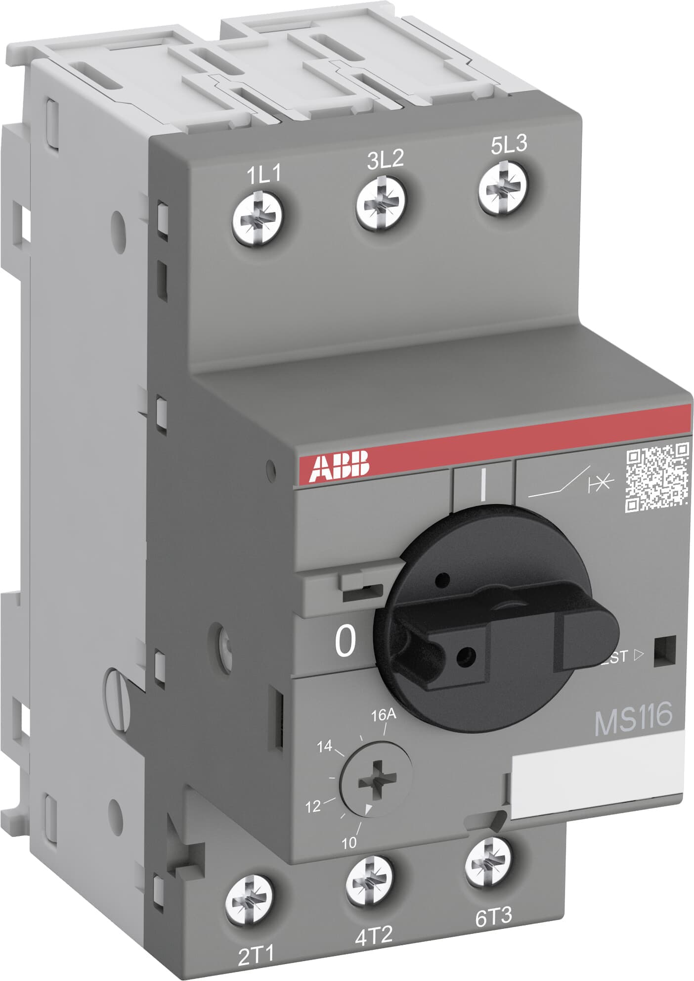
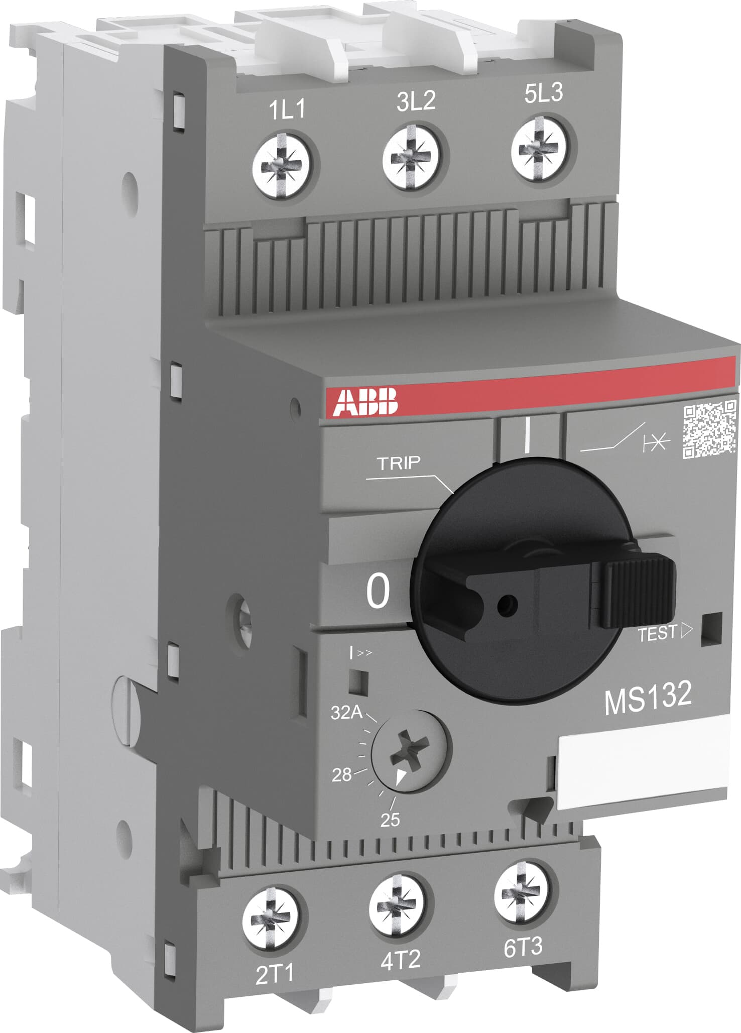
Motor Protection Switch
A motor protection switch combines a manual on/off function with thermal-magnetic overload and short-circuit tripping in one device, sized to the exact full-load current of the motor it protects rather than to the switchboard feeder rating.
Read more — Motor Protection Switch explained ▾
What defines a motor protection switch
A motor protection switch (often called a motor circuit breaker or MPCB) is a manually operated switch and a protective device in one housing, dedicated to a single motor rather than a whole distribution board section. It differs from a plain fuse-switch or an air circuit breaker in that its overload trip curve is set to the motor's actual full-load current, not to the cable's current-carrying capacity, and it trips on an inverse-time thermal curve for overload plus an instantaneous magnetic trip for short-circuit and locked-rotor current. Where a contactor alone switches the motor on and off under normal control-system command, the protection switch is the device that removes power when something has already gone wrong -- overload, phase loss, or a direct fault downstream.

Main components
Trip unit
A thermal-magnetic trip unit (or, on larger frames, an electronic trip unit) that combines an adjustable overload setting -- usually a dial covering a current range around the motor's rated current -- with a fixed or adjustable short-circuit trip several times higher.
Operating mechanism
A quick-make, quick-break toggle or rotary handle, independent of how fast the operator moves it, so contact welding on a heavy fault current does not delay the trip.
Auxiliary and alarm contacts
Change-over contacts that report the switch position and trip status to the alarm and monitoring system, so a tripped motor shows on the bridge or engine control room panel rather than only being discovered locally.
Phase failure protection
Most marine types include single-phasing protection, since a motor running on two phases after losing one draws sharply higher current in the remaining windings and can burn out within minutes if the thermal trip alone is relied on.
Selection and sizing
- Full-load current of the motor at its nameplate voltage and duty, not the feeder cable rating.
- Starting current and starting time, since the trip curve must ride through a normal start without nuisance tripping.
- Short-circuit breaking capacity at the switchboard fault level, which is higher close to the busbar than at the end of a long feeder.
- Duty type -- continuous, intermittent, or reversing service such as a winch -- which changes the thermal trip class required.
- Ambient temperature at the installation point, since switchgear in an engine room runs hotter than an air-conditioned control room and the trip curve needs compensation.
Regulations and class
Class rules require overload and short-circuit protection on every motor circuit above a small rating threshold, plus single-phasing protection on three-phase motors driving essential services. Motors feeding steering gear, fire pumps and other essential services have additional requirements around where the protection is allowed to trip the motor versus only alarm and let it run -- SOLAS Ch. II-1 sets out which essential auxiliaries must not be tripped on overload alone, only alarmed, so that steering is not lost to a nuisance trip in heavy weather. Surveyors check the trip settings against the motor nameplate at commissioning and again at periodic survey, since a setting left at factory default rather than the actual motor current is a common finding.
Typical faults
| Fault | Cause | Consequence |
|---|---|---|
| Nuisance tripping on start | Overload setting too close to full-load current for a motor with a long or heavy start | Repeated failed starts, crew resets the trip without addressing the cause, eventual real overload undetected |
| Trip unit fails to operate on a genuine overload | Contacts welded from a previous fault, or thermal element degraded by age and heat cycling | Motor winding burns out instead of the switch tripping |
| Single-phasing goes undetected | Phase failure protection not fitted or disabled after a previous nuisance trip | Motor continues running on two phases until thermal damage or complete failure |
| Auxiliary contact signal lost | Loose wiring on the remote indication contacts, often after switchboard vibration over years of service | Control room shows a motor running when it has actually tripped locally |
What to look for in a supplier
- Type test certificate showing short-circuit breaking capacity at the actual switchboard fault level, not just a generic rating.
- Trip curve documentation the ship's electrician can use to reset and verify the setting after motor replacement.
- Spares availability for the specific frame size already installed, since protection switches are rarely interchangeable across manufacturers without rewiring the panel.
- Auxiliary contact configuration matching the existing alarm and monitoring wiring.
When a motor is replaced with one of a different rating, the protection switch setting has to be recalculated and re-set at the same time -- leaving the old setting in place is a routine oversight that turns the switch into a piece of decoration rather than protection.
3 manufacturers · 99 models
Siemens
45ABB
27