What to check on a Battery/UPS.
A marine battery and uninterruptible power supply system holds a defined set of loads on continuous power through any interruption of the main and emergency supply. It differs from a standalone starting battery bank in that it is permanently connected through a static inverter, so the changeover to battery power happens without a switch or relay closing, and without any interruption the connected equipment would notice. Typical protected loads are navigation lights, the gyrocompass, radio and GMDSS equipment, alarm and monitoring systems, and emergency lighting in machinery spaces and control…
What defines a battery/UPS system
A marine battery and uninterruptible power supply system holds a defined set of loads on continuous power through any interruption of the main and emergency supply. It differs from a standalone starting battery bank in that it is permanently connected through a static inverter, so the changeover to battery power happens without a switch or relay closing, and without any interruption the connected equipment would notice. Typical protected loads are navigation lights, the gyrocompass, radio and GMDSS equipment, alarm and monitoring systems, and emergency lighting in machinery spaces and control rooms.
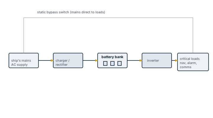
Main components
Battery bank
Vented lead-acid, valve-regulated lead-acid or, increasingly, lithium iron phosphate cells are arranged in strings to give the required DC voltage and autonomy time. Lithium chemistries reduce weight and maintenance but require a dedicated battery management system and stricter ventilation and fire protection arrangements than lead-acid.
Charger/rectifier
Converts AC supply to DC to keep the battery bank at float charge and to recharge it after a discharge event, with a boost charge stage for faster recovery.
Static inverter
Converts battery DC back to AC to feed the protected loads continuously, taking over the supply within milliseconds if the main AC input fails.
Battery monitoring and BMS
Tracks cell voltage, temperature and state of charge, and on lithium systems will isolate a faulty string automatically to prevent thermal runaway spreading to adjacent cells.
Ventilation
Vented lead-acid batteries release hydrogen during charging and require forced ventilation of the battery space with a minimum air change rate; sealed and lithium types have lower but not zero ventilation demand.
Selection and sizing
Autonomy time, the duration the bank must supply its loads without recharge, drives capacity and is set against class rules for the specific consumers involved, commonly 30 minutes to several hours depending on the load category. Load is calculated from the actual connected equipment, not from a generic allowance, since GMDSS and navigation loads are fixed by regulation while alarm and monitoring loads vary by ship. Voltage class, 24V and 220V DC systems are both common, must match the connected equipment without an extra conversion stage that adds a failure point.
Regulations and class
SOLAS Chapter II-1 sets minimum autonomy for the emergency source of electrical power and for transitional supply before the emergency generator starts. GMDSS battery capacity is separately specified under SOLAS Chapter IV. Class societies require periodic capacity testing, typically an annual discharge test, to confirm the bank still meets its rated autonomy as cells age.
Typical faults
| Fault | Consequence |
|---|---|
| Cell sulphation from prolonged undercharge | Falling capacity, bank no longer meets its rated autonomy |
| Electrolyte level neglected on vented lead-acid cells | Plate damage and accelerated capacity loss |
| Charger fault going unnoticed | Bank discharges slowly in the background, found empty when actually needed |
| Poor ventilation or blocked vents | Hydrogen accumulation, an explosion risk during charging |
| Loose or corroded terminal connections | High resistance, local heating, and unreliable transfer under load |
What to look for in a supplier
- Type approval matching the specific class notation and SOLAS category of the loads to be protected
- Clear autonomy figures at the actual connected load, not at a nominal or best-case rating
- Battery management system with cell-level monitoring on any lithium installation
- Compatibility with the ship's existing charger and DC distribution voltage
A UPS that has never been discharge-tested is an assumption, not a fact; schedule the annual capacity test and log the actual runtime against the rated figure.