"> Radar - Equipment Database

Radar

medium 458 models total

Marine radar detects targets by timing the echo of a transmitted pulse, and the practical difference between units comes down to band, X-band versus S-band, because that choice trades fine resolution against performance in rain and sea clutter.

Read more — Radar explained

What sets radar apart from the rest of the navigation suite

Radar is an active sensor: it transmits its own pulses and measures the echo, so it works independently of satellite signals, AIS transponders on other vessels, or visibility, which is why it remains the primary anti-collision and landfall tool when everything else fails. The main design choice within radar itself is frequency band. X-band (around 9 GHz) gives a shorter wavelength and finer resolution, so it is the standard choice for target discrimination and close-range collision avoidance. S-band (around 3 GHz) has a longer wavelength that penetrates rain and sea clutter far better, at the cost of coarser resolution, which is why SOLAS ships over a certain size are required to carry both: X-band for detail, S-band for reliable detection in heavy weather. A single-band fit is a real operational limitation, not just a cost saving, because neither band alone covers both jobs well.
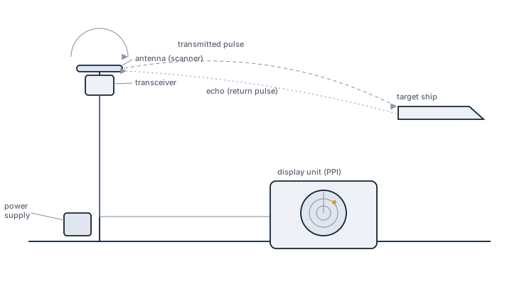
Marine radar, working principle
Shipboard radar arrangement showing the rotating antenna and transceiver on the mast, the transmitted pulse travelling to a target and the echo returning, and the display unit at the bridge showing the resulting plan position indicator picture.

Main components

Transceiver / scanner unit

Combines the transmitter, receiver and rotating antenna in one mast-mounted unit on modern solid-state sets, replacing the older separate magnetron transmitter and antenna arrangement found on legacy pulse radars.

Antenna

A rotating slotted waveguide array; longer antennas give finer bearing resolution, which is why larger vessels fit longer scanners than small craft.

Display and processor

Processes the returned echoes into the plan position indicator picture, runs target tracking (ARPA), and on integrated bridge systems overlays the radar picture onto ECDIS chart data.

Transmitter technology

Magnetron sets generate high-power short pulses and are simple and robust but wear out, since the magnetron itself is a consumable; solid-state pulse-compression sets use lower peak power over a longer, coded pulse, giving comparable range performance with no magnetron replacement and generally better short-range clutter performance.

Selection and sizing

  • Vessel size and SOLAS category - determines whether one or two radars are required, and whether S-band is mandatory alongside X-band.
  • Antenna length - longer antenna improves bearing discrimination between close targets, relevant in traffic-dense or coastal navigation.
  • Transmitter technology - magnetron versus solid-state trades upfront simplicity against long-term maintenance cost and clutter performance.
  • Integration - whether the radar needs to feed a full integrated bridge/ECDIS overlay or stand alone.

Regulations and class

SOLAS Chapter V sets the carriage requirements: cargo ships of 3,000 gross tonnage and upwards and passenger ships must carry two radar systems capable of operating independently, one of which must be a 9 GHz (X-band) set, arranged so that failure of one does not disable the other. Radar equipment must meet IMO performance standards and carry type approval referencing the relevant IEC test standard. Class and flag state surveys check the radar is operational, correctly interfaced to gyro/heading and speed inputs, and that the required second unit is genuinely independent, not sharing a single point of failure with the first.

Typical faults

  • Magnetron degradation - a slow drop in transmitted power reduces detection range long before the set fails outright, often unnoticed until a comparison with the second radar reveals it.
  • Antenna motor or bearing wear - irregular rotation speed distorts the picture and can eventually stop the scanner entirely.
  • Waveguide or antenna joint corrosion - moisture ingress attenuates the signal, showing up as reduced range performance that is easy to mistake for a transmitter fault.
  • Heading/speed input failure - a lost gyro or log feed degrades ARPA target tracking accuracy even though the radar picture itself looks normal.

What to look for in a supplier

  • Type approval certificate confirming compliance with current IMO radar performance standards for the vessel's SOLAS category.
  • Confirmed independence of the two required radar installations, down to separate power supplies where required.
  • Spares and service support for the transmitter technology fitted, particularly magnetron replacement lead time if that technology is retained.

Compare both radars against each other regularly, not just against the chart - a slowly failing magnetron loses range gradually, and the difference only becomes obvious when the second, healthy set is checked side by side.

20 manufacturers · 458 models

Furuno

119
FAR-1513 3.9ft Open unverified
Frequency band
X-Band
Antenna type
3.9ft Open
Display size (Zoll)
12
IMO Compliant
ja
Common Failures & Inspection Points
  • Loss of sensor input or damaged cabling causes missing, frozen or implausible navigation data
  • Antenna, transducer or scanner faults reduce detection or measurement performance and generate equipment alarms
  • Power-supply or cooling faults cause resets, blank displays or complete loss of function
  • Configuration or interface faults cause disagreement between systems or missing data on connected equipment
  • Display, control or processing faults cause unstable operation, error messages or inability to select required functions
Service: Check power supplies, data interfaces, alarms, sensor health and agreement with independent navigation information where practical. Inspect external antennas, scanners or transducers as applicable and review fault logs and self-test results. Verify required backups, records and bridge procedures; exact calibration tolerances and test methods must follow manufacturer and statutory documentation.
Spare Parts: Typical spares include approved fuses, cooling fans, display or keypad parts where supported, interface modules, data cables and selected sensor or antenna components according to the vessel's critical-spares policy.
Use Cases: Used on commercial and offshore vessels for navigation, collision avoidance, route monitoring, heading control and voyage recording according to the specific equipment type.
FAR-1513 4ft Slotted unverified
Frequency band
X-Band
Antenna type
4ft Slotted
Display size (Zoll)
12
IMO Compliant
ja
Common Failures & Inspection Points
  • Loss of sensor input or damaged cabling causes missing, frozen or implausible navigation data
  • Antenna, transducer or scanner faults reduce detection or measurement performance and generate equipment alarms
  • Power-supply or cooling faults cause resets, blank displays or complete loss of function
  • Configuration or interface faults cause disagreement between systems or missing data on connected equipment
  • Display, control or processing faults cause unstable operation, error messages or inability to select required functions
Service: Check power supplies, data interfaces, alarms, sensor health and agreement with independent navigation information where practical. Inspect external antennas, scanners or transducers as applicable and review fault logs and self-test results. Verify required backups, records and bridge procedures; exact calibration tolerances and test methods must follow manufacturer and statutory documentation.
Spare Parts: Typical spares include approved fuses, cooling fans, display or keypad parts where supported, interface modules, data cables and selected sensor or antenna components according to the vessel's critical-spares policy.
Use Cases: Used on commercial and offshore vessels for navigation, collision avoidance, route monitoring, heading control and voyage recording according to the specific equipment type.
FAR-1513 6ft Open unverified
Frequency band
X-Band
Antenna type
6ft Open
Display size (Zoll)
12
IMO Compliant
ja
Common Failures & Inspection Points
  • Scanner-drive or bearing faults cause irregular antenna rotation, mechanical noise or loss of radar picture
  • Transmitter or solid-state RF-stage deterioration reduces detection range and produces weak echoes or transmitter alarms
  • Waveguide, RF cable or connector moisture causes attenuation, unstable performance or intermittent faults
  • Display, processor or network faults cause frozen images, loss of controls or missing radar presentation
  • Heading, speed or position-input faults distort stabilization, target vectors or overlays and generate sensor alarms
Service: Inspect scanner, pedestal, seals, RF path, display, processor, cooling and power supplies. Verify heading and speed inputs, tuning or automatic optimization, target tracking and alignment using approved checks. Review alarms and event logs. Refer to manufacturer documentation for the exact figure for transmitter tests, alignment and performance limits.
Spare Parts: Carry fuses, cooling fans, approved power-supply modules, network or interface cables, display controls and scanner-drive service parts where supported.
Use Cases: Collision avoidance, coastal navigation, pilotage and traffic monitoring on merchant, passenger, offshore and service vessels.
FAR-1513 6.5ft Slotted unverified
Frequency band
X-Band
Antenna type
6.5ft Slotted
Display size (Zoll)
12
IMO Compliant
ja
Common Failures & Inspection Points
  • Sensor, antenna or transducer fouling, damage or misalignment causes unstable, missing or inaccurate data
  • Power-supply or processor faults cause resets, blank displays or complete loss of indication
  • Cable, connector or network faults cause intermittent data or loss of outputs to other bridge systems
  • Incorrect configuration or calibration causes persistent disagreement with independent references
  • Display or software faults cause frozen values, alarms or unavailable functions
Service: Inspect sensors, antennas, transducers, cabling, power supplies, displays and data interfaces. Compare information with independent references and review alarm history. Verify distribution to dependent bridge systems. Refer to the manufacturer documentation for the exact figure for calibration, alignment and performance criteria.
Spare Parts: Carry fuses, interface cables, approved power supplies, sensor or antenna parts and supported display or processor modules.
Use Cases: Navigation, pilotage, collision avoidance and bridge-system integration.
FAR-1518 3.9ft Open unverified
Frequency band
X-Band
Antenna type
3.9ft Open
Display size (Zoll)
19
IMO Compliant
ja
Common Failures & Inspection Points
  • Loss of sensor input or damaged cabling causes missing, frozen or implausible navigation data
  • Antenna, transducer or scanner faults reduce detection or measurement performance and generate equipment alarms
  • Power-supply or cooling faults cause resets, blank displays or complete loss of function
  • Configuration or interface faults cause disagreement between systems or missing data on connected equipment
  • Display, control or processing faults cause unstable operation, error messages or inability to select required functions
Service: Check power supplies, data interfaces, alarms, sensor health and agreement with independent navigation information where practical. Inspect external antennas, scanners or transducers as applicable and review fault logs and self-test results. Verify required backups, records and bridge procedures; exact calibration tolerances and test methods must follow manufacturer and statutory documentation.
Spare Parts: Typical spares include approved fuses, cooling fans, display or keypad parts where supported, interface modules, data cables and selected sensor or antenna components according to the vessel's critical-spares policy.
Use Cases: Used on commercial and offshore vessels for navigation, collision avoidance, route monitoring, heading control and voyage recording according to the specific equipment type.
FAR-1518 4ft Slotted unverified
Frequency band
X-Band
Antenna type
4ft Slotted
Display size (Zoll)
19
IMO Compliant
ja
Common Failures & Inspection Points
  • Loss of sensor input or damaged cabling causes missing, frozen or implausible navigation data
  • Antenna, transducer or scanner faults reduce detection or measurement performance and generate equipment alarms
  • Power-supply or cooling faults cause resets, blank displays or complete loss of function
  • Configuration or interface faults cause disagreement between systems or missing data on connected equipment
  • Display, control or processing faults cause unstable operation, error messages or inability to select required functions
Service: Check power supplies, data interfaces, alarms, sensor health and agreement with independent navigation information where practical. Inspect external antennas, scanners or transducers as applicable and review fault logs and self-test results. Verify required backups, records and bridge procedures; exact calibration tolerances and test methods must follow manufacturer and statutory documentation.
Spare Parts: Typical spares include approved fuses, cooling fans, display or keypad parts where supported, interface modules, data cables and selected sensor or antenna components according to the vessel's critical-spares policy.
Use Cases: Used on commercial and offshore vessels for navigation, collision avoidance, route monitoring, heading control and voyage recording according to the specific equipment type.
FAR-1518 6ft Open unverified
Frequency band
X-Band
Antenna type
6ft Open
Display size (Zoll)
19
IMO Compliant
ja
Common Failures & Inspection Points
  • Scanner-drive or bearing faults cause irregular antenna rotation, mechanical noise or loss of radar picture
  • Transmitter or solid-state RF-stage deterioration reduces detection range and produces weak echoes or transmitter alarms
  • Waveguide, RF cable or connector moisture causes attenuation, unstable performance or intermittent faults
  • Display, processor or network faults cause frozen images, loss of controls or missing radar presentation
  • Heading, speed or position-input faults distort stabilization, target vectors or overlays and generate sensor alarms
Service: Inspect scanner, pedestal, seals, RF path, display, processor, cooling and power supplies. Verify heading and speed inputs, tuning or automatic optimization, target tracking and alignment using approved checks. Review alarms and event logs. Refer to manufacturer documentation for the exact figure for transmitter tests, alignment and performance limits.
Spare Parts: Carry fuses, cooling fans, approved power-supply modules, network or interface cables, display controls and scanner-drive service parts where supported.
Use Cases: Collision avoidance, coastal navigation, pilotage and traffic monitoring on merchant, passenger, offshore and service vessels.
FAR-1518 6.5ft Slotted unverified
Frequency band
X-Band
Antenna type
6.5ft Slotted
Display size (Zoll)
19
IMO Compliant
ja
Common Failures & Inspection Points
  • Sensor, antenna or transducer fouling, damage or misalignment causes unstable, missing or inaccurate data
  • Power-supply or processor faults cause resets, blank displays or complete loss of indication
  • Cable, connector or network faults cause intermittent data or loss of outputs to other bridge systems
  • Incorrect configuration or calibration causes persistent disagreement with independent references
  • Display or software faults cause frozen values, alarms or unavailable functions
Service: Inspect sensors, antennas, transducers, cabling, power supplies, displays and data interfaces. Compare information with independent references and review alarm history. Verify distribution to dependent bridge systems. Refer to the manufacturer documentation for the exact figure for calibration, alignment and performance criteria.
Spare Parts: Carry fuses, interface cables, approved power supplies, sensor or antenna parts and supported display or processor modules.
Use Cases: Navigation, pilotage, collision avoidance and bridge-system integration.
FAR-1523 3.9ft Open unverified
Frequency band
X-Band
Antenna type
3.9ft Open
Display size (Zoll)
19
IMO Compliant
ja
Common Failures & Inspection Points
  • Loss of sensor input or damaged cabling causes missing, frozen or implausible navigation data
  • Antenna, transducer or scanner faults reduce detection or measurement performance and generate equipment alarms
  • Power-supply or cooling faults cause resets, blank displays or complete loss of function
  • Configuration or interface faults cause disagreement between systems or missing data on connected equipment
  • Display, control or processing faults cause unstable operation, error messages or inability to select required functions
Service: Check power supplies, data interfaces, alarms, sensor health and agreement with independent navigation information where practical. Inspect external antennas, scanners or transducers as applicable and review fault logs and self-test results. Verify required backups, records and bridge procedures; exact calibration tolerances and test methods must follow manufacturer and statutory documentation.
Spare Parts: Typical spares include approved fuses, cooling fans, display or keypad parts where supported, interface modules, data cables and selected sensor or antenna components according to the vessel's critical-spares policy.
Use Cases: Used on commercial and offshore vessels for navigation, collision avoidance, route monitoring, heading control and voyage recording according to the specific equipment type.
FAR-1523 4ft Slotted unverified
Frequency band
X-Band
Antenna type
4ft Slotted
Display size (Zoll)
19
IMO Compliant
ja
Common Failures & Inspection Points
  • Loss of sensor input or damaged cabling causes missing, frozen or implausible navigation data
  • Antenna, transducer or scanner faults reduce detection or measurement performance and generate equipment alarms
  • Power-supply or cooling faults cause resets, blank displays or complete loss of function
  • Configuration or interface faults cause disagreement between systems or missing data on connected equipment
  • Display, control or processing faults cause unstable operation, error messages or inability to select required functions
Service: Check power supplies, data interfaces, alarms, sensor health and agreement with independent navigation information where practical. Inspect external antennas, scanners or transducers as applicable and review fault logs and self-test results. Verify required backups, records and bridge procedures; exact calibration tolerances and test methods must follow manufacturer and statutory documentation.
Spare Parts: Typical spares include approved fuses, cooling fans, display or keypad parts where supported, interface modules, data cables and selected sensor or antenna components according to the vessel's critical-spares policy.
Use Cases: Used on commercial and offshore vessels for navigation, collision avoidance, route monitoring, heading control and voyage recording according to the specific equipment type.
FAR-1523 6ft Open unverified
Frequency band
X-Band
Antenna type
6ft Open
Display size (Zoll)
19
IMO Compliant
ja
Common Failures & Inspection Points
  • Scanner-drive or bearing faults cause irregular antenna rotation, mechanical noise or loss of radar picture
  • Transmitter or solid-state RF-stage deterioration reduces detection range and produces weak echoes or transmitter alarms
  • Waveguide, RF cable or connector moisture causes attenuation, unstable performance or intermittent faults
  • Display, processor or network faults cause frozen images, loss of controls or missing radar presentation
  • Heading, speed or position-input faults distort stabilization, target vectors or overlays and generate sensor alarms
Service: Inspect scanner, pedestal, seals, RF path, display, processor, cooling and power supplies. Verify heading and speed inputs, tuning or automatic optimization, target tracking and alignment using approved checks. Review alarms and event logs. Refer to manufacturer documentation for the exact figure for transmitter tests, alignment and performance limits.
Spare Parts: Carry fuses, cooling fans, approved power-supply modules, network or interface cables, display controls and scanner-drive service parts where supported.
Use Cases: Collision avoidance, coastal navigation, pilotage and traffic monitoring on merchant, passenger, offshore and service vessels.
FAR-1523 6.5ft Slotted unverified
Frequency band
X-Band
Antenna type
6.5ft Slotted
Display size (Zoll)
19
IMO Compliant
ja
Common Failures & Inspection Points
  • Sensor, antenna or transducer fouling, damage or misalignment causes unstable, missing or inaccurate data
  • Power-supply or processor faults cause resets, blank displays or complete loss of indication
  • Cable, connector or network faults cause intermittent data or loss of outputs to other bridge systems
  • Incorrect configuration or calibration causes persistent disagreement with independent references
  • Display or software faults cause frozen values, alarms or unavailable functions
Service: Inspect sensors, antennas, transducers, cabling, power supplies, displays and data interfaces. Compare information with independent references and review alarm history. Verify distribution to dependent bridge systems. Refer to the manufacturer documentation for the exact figure for calibration, alignment and performance criteria.
Spare Parts: Carry fuses, interface cables, approved power supplies, sensor or antenna parts and supported display or processor modules.
Use Cases: Navigation, pilotage, collision avoidance and bridge-system integration.
FAR-1528 3.9ft Open unverified
Frequency band
X-Band
Antenna type
3.9ft Open
Display size (Zoll)
19
IMO Compliant
ja
Common Failures & Inspection Points
  • Loss of sensor input or damaged cabling causes missing, frozen or implausible navigation data
  • Antenna, transducer or scanner faults reduce detection or measurement performance and generate equipment alarms
  • Power-supply or cooling faults cause resets, blank displays or complete loss of function
  • Configuration or interface faults cause disagreement between systems or missing data on connected equipment
  • Display, control or processing faults cause unstable operation, error messages or inability to select required functions
Service: Check power supplies, data interfaces, alarms, sensor health and agreement with independent navigation information where practical. Inspect external antennas, scanners or transducers as applicable and review fault logs and self-test results. Verify required backups, records and bridge procedures; exact calibration tolerances and test methods must follow manufacturer and statutory documentation.
Spare Parts: Typical spares include approved fuses, cooling fans, display or keypad parts where supported, interface modules, data cables and selected sensor or antenna components according to the vessel's critical-spares policy.
Use Cases: Used on commercial and offshore vessels for navigation, collision avoidance, route monitoring, heading control and voyage recording according to the specific equipment type.
FAR-1528 4ft Slotted unverified
Frequency band
X-Band
Antenna type
4ft Slotted
Display size (Zoll)
19
IMO Compliant
ja
Common Failures & Inspection Points
  • Loss of sensor input or damaged cabling causes missing, frozen or implausible navigation data
  • Antenna, transducer or scanner faults reduce detection or measurement performance and generate equipment alarms
  • Power-supply or cooling faults cause resets, blank displays or complete loss of function
  • Configuration or interface faults cause disagreement between systems or missing data on connected equipment
  • Display, control or processing faults cause unstable operation, error messages or inability to select required functions
Service: Check power supplies, data interfaces, alarms, sensor health and agreement with independent navigation information where practical. Inspect external antennas, scanners or transducers as applicable and review fault logs and self-test results. Verify required backups, records and bridge procedures; exact calibration tolerances and test methods must follow manufacturer and statutory documentation.
Spare Parts: Typical spares include approved fuses, cooling fans, display or keypad parts where supported, interface modules, data cables and selected sensor or antenna components according to the vessel's critical-spares policy.
Use Cases: Used on commercial and offshore vessels for navigation, collision avoidance, route monitoring, heading control and voyage recording according to the specific equipment type.
FAR-1528 6ft Open unverified
Frequency band
X-Band
Antenna type
6ft Open
Display size (Zoll)
19
IMO Compliant
ja
Common Failures & Inspection Points
  • Scanner-drive or bearing faults cause irregular antenna rotation, mechanical noise or loss of radar picture
  • Transmitter or solid-state RF-stage deterioration reduces detection range and produces weak echoes or transmitter alarms
  • Waveguide, RF cable or connector moisture causes attenuation, unstable performance or intermittent faults
  • Display, processor or network faults cause frozen images, loss of controls or missing radar presentation
  • Heading, speed or position-input faults distort stabilization, target vectors or overlays and generate sensor alarms
Service: Inspect scanner, pedestal, seals, RF path, display, processor, cooling and power supplies. Verify heading and speed inputs, tuning or automatic optimization, target tracking and alignment using approved checks. Review alarms and event logs. Refer to manufacturer documentation for the exact figure for transmitter tests, alignment and performance limits.
Spare Parts: Carry fuses, cooling fans, approved power-supply modules, network or interface cables, display controls and scanner-drive service parts where supported.
Use Cases: Collision avoidance, coastal navigation, pilotage and traffic monitoring on merchant, passenger, offshore and service vessels.
FAR-1528 6.5ft Slotted unverified
Frequency band
X-Band
Antenna type
6.5ft Slotted
Display size (Zoll)
19
IMO Compliant
ja
Common Failures & Inspection Points
  • Sensor, antenna or transducer fouling, damage or misalignment causes unstable, missing or inaccurate data
  • Power-supply or processor faults cause resets, blank displays or complete loss of indication
  • Cable, connector or network faults cause intermittent data or loss of outputs to other bridge systems
  • Incorrect configuration or calibration causes persistent disagreement with independent references
  • Display or software faults cause frozen values, alarms or unavailable functions
Service: Inspect sensors, antennas, transducers, cabling, power supplies, displays and data interfaces. Compare information with independent references and review alarm history. Verify distribution to dependent bridge systems. Refer to the manufacturer documentation for the exact figure for calibration, alignment and performance criteria.
Spare Parts: Carry fuses, interface cables, approved power supplies, sensor or antenna parts and supported display or processor modules.
Use Cases: Navigation, pilotage, collision avoidance and bridge-system integration.
FAR-2117 3.9ft Open unverified
Frequency band
X-Band
Antenna type
3.9ft Open
Display size (Zoll)
17
IMO Compliant
ja
Arpa
ja
Common Failures & Inspection Points
  • Loss of sensor input or damaged cabling causes missing, frozen or implausible navigation data
  • Antenna, transducer or scanner faults reduce detection or measurement performance and generate equipment alarms
  • Power-supply or cooling faults cause resets, blank displays or complete loss of function
  • Configuration or interface faults cause disagreement between systems or missing data on connected equipment
  • Display, control or processing faults cause unstable operation, error messages or inability to select required functions
Service: Check power supplies, data interfaces, alarms, sensor health and agreement with independent navigation information where practical. Inspect external antennas, scanners or transducers as applicable and review fault logs and self-test results. Verify required backups, records and bridge procedures; exact calibration tolerances and test methods must follow manufacturer and statutory documentation.
Spare Parts: Typical spares include approved fuses, cooling fans, display or keypad parts where supported, interface modules, data cables and selected sensor or antenna components according to the vessel's critical-spares policy.
Use Cases: Used on commercial and offshore vessels for navigation, collision avoidance, route monitoring, heading control and voyage recording according to the specific equipment type.
FAR-2117 6.5ft Slotted unverified
Frequency band
X-Band
Antenna type
6.5ft Slotted
Display size (Zoll)
17
IMO Compliant
ja
Arpa
ja
Common Failures & Inspection Points
  • Sensor, antenna or transducer fouling, damage or misalignment causes unstable, missing or inaccurate data
  • Power-supply or processor faults cause resets, blank displays or complete loss of indication
  • Cable, connector or network faults cause intermittent data or loss of outputs to other bridge systems
  • Incorrect configuration or calibration causes persistent disagreement with independent references
  • Display or software faults cause frozen values, alarms or unavailable functions
Service: Inspect sensors, antennas, transducers, cabling, power supplies, displays and data interfaces. Compare information with independent references and review alarm history. Verify distribution to dependent bridge systems. Refer to the manufacturer documentation for the exact figure for calibration, alignment and performance criteria.
Spare Parts: Carry fuses, interface cables, approved power supplies, sensor or antenna parts and supported display or processor modules.
Use Cases: Navigation, pilotage, collision avoidance and bridge-system integration.
FAR-2117 8ft Open unverified
Frequency band
X-Band
Antenna type
8ft Open
Display size (Zoll)
17
IMO Compliant
ja
Arpa
ja
Common Failures & Inspection Points
  • Scanner-drive or bearing faults cause irregular antenna rotation, mechanical noise or loss of radar picture
  • Transmitter or solid-state RF-stage deterioration reduces detection range and produces weak echoes or transmitter alarms
  • Waveguide, RF cable or connector moisture causes attenuation, unstable performance or intermittent faults
  • Display, processor or network faults cause frozen images, loss of controls or missing radar presentation
  • Heading, speed or position-input faults distort stabilization, target vectors or overlays and generate sensor alarms
Service: Inspect scanner, pedestal, seals, RF path, display, processor, cooling and power supplies. Verify heading and speed inputs, tuning or automatic optimization, target tracking and alignment using approved checks. Review alarms and event logs. Refer to manufacturer documentation for the exact figure for transmitter tests, alignment and performance limits.
Spare Parts: Carry fuses, cooling fans, approved power-supply modules, network or interface cables, display controls and scanner-drive service parts where supported.
Use Cases: Collision avoidance, coastal navigation, pilotage and traffic monitoring on merchant, passenger, offshore and service vessels.
FAR-2117 12ft Slotted unverified
Frequency band
X-Band
Antenna type
12ft Slotted
Display size (Zoll)
17
IMO Compliant
ja
Arpa
ja
Common Failures & Inspection Points
  • Antenna drive or rotation failure caused by motor, gearbox, bearing or power faults, resulting in loss of scan or radar alarm
  • Transmitter or RF-stage failure caused by component aging or electrical faults, resulting in weak or absent target returns
  • Heading, speed or position-input failure caused by sensor or network faults, resulting in incorrect stabilization or target vectors
  • Display or processing fault caused by software, power-supply or hardware problems, resulting in frozen, blank or corrupted presentation
  • Antenna-window contamination or water ingress caused by salt, moisture or seal deterioration, resulting in reduced range, intermittent faults or corrosion
Service: Inspect antenna rotation, scanner condition, waveguide or cabling, power supplies and bridge connections. Verify heading, speed and position inputs are valid and compare radar presentation with known targets. Check alarms, guard functions and target-tracking behavior using the vessel's approved test procedure. Inspect exposed scanner housings for salt, water ingress and damaged seals and maintain safe RF isolation before work aloft. Back up configuration data where supported and document software or hardware changes. Refer to manufacturer documentation for exact performance tests, transmitter servicing and alignment procedures.
Spare Parts: Keep fuses, power-supply modules or approved electronic spares, scanner-drive consumables, seals and interface components recommended for the installed radar. Where the design uses a serviceable transmitter component with a finite life, follow the manufacturer's spare strategy. Ensure replacement modules preserve type approval and software compatibility.
Use Cases: Bridge navigation, collision avoidance, coastal pilotage and situational awareness on merchant ships, offshore vessels and workboats.
FAR-2127 3.9ft Open unverified
Frequency band
X-Band
Antenna type
3.9ft Open
Display size (Zoll)
27
IMO Compliant
ja
Arpa
ja
Common Failures & Inspection Points
  • Loss of sensor input or damaged cabling causes missing, frozen or implausible navigation data
  • Antenna, transducer or scanner faults reduce detection or measurement performance and generate equipment alarms
  • Power-supply or cooling faults cause resets, blank displays or complete loss of function
  • Configuration or interface faults cause disagreement between systems or missing data on connected equipment
  • Display, control or processing faults cause unstable operation, error messages or inability to select required functions
Service: Check power supplies, data interfaces, alarms, sensor health and agreement with independent navigation information where practical. Inspect external antennas, scanners or transducers as applicable and review fault logs and self-test results. Verify required backups, records and bridge procedures; exact calibration tolerances and test methods must follow manufacturer and statutory documentation.
Spare Parts: Typical spares include approved fuses, cooling fans, display or keypad parts where supported, interface modules, data cables and selected sensor or antenna components according to the vessel's critical-spares policy.
Use Cases: Used on commercial and offshore vessels for navigation, collision avoidance, route monitoring, heading control and voyage recording according to the specific equipment type.
FAR-2127 6.5ft Slotted unverified
Frequency band
X-Band
Antenna type
6.5ft Slotted
Display size (Zoll)
27
IMO Compliant
ja
Arpa
ja
Common Failures & Inspection Points
  • Sensor, antenna or transducer fouling, damage or misalignment causes unstable, missing or inaccurate data
  • Power-supply or processor faults cause resets, blank displays or complete loss of indication
  • Cable, connector or network faults cause intermittent data or loss of outputs to other bridge systems
  • Incorrect configuration or calibration causes persistent disagreement with independent references
  • Display or software faults cause frozen values, alarms or unavailable functions
Service: Inspect sensors, antennas, transducers, cabling, power supplies, displays and data interfaces. Compare information with independent references and review alarm history. Verify distribution to dependent bridge systems. Refer to the manufacturer documentation for the exact figure for calibration, alignment and performance criteria.
Spare Parts: Carry fuses, interface cables, approved power supplies, sensor or antenna parts and supported display or processor modules.
Use Cases: Navigation, pilotage, collision avoidance and bridge-system integration.
FAR-2127 8ft Open unverified
Frequency band
X-Band
Antenna type
8ft Open
Display size (Zoll)
27
IMO Compliant
ja
Arpa
ja
Common Failures & Inspection Points
  • Scanner-drive or bearing faults cause irregular antenna rotation, mechanical noise or loss of radar picture
  • Transmitter or solid-state RF-stage deterioration reduces detection range and produces weak echoes or transmitter alarms
  • Waveguide, RF cable or connector moisture causes attenuation, unstable performance or intermittent faults
  • Display, processor or network faults cause frozen images, loss of controls or missing radar presentation
  • Heading, speed or position-input faults distort stabilization, target vectors or overlays and generate sensor alarms
Service: Inspect scanner, pedestal, seals, RF path, display, processor, cooling and power supplies. Verify heading and speed inputs, tuning or automatic optimization, target tracking and alignment using approved checks. Review alarms and event logs. Refer to manufacturer documentation for the exact figure for transmitter tests, alignment and performance limits.
Spare Parts: Carry fuses, cooling fans, approved power-supply modules, network or interface cables, display controls and scanner-drive service parts where supported.
Use Cases: Collision avoidance, coastal navigation, pilotage and traffic monitoring on merchant, passenger, offshore and service vessels.
FAR-2127 12ft Slotted unverified
Frequency band
X-Band
Antenna type
12ft Slotted
Display size (Zoll)
27
IMO Compliant
ja
Arpa
ja
Common Failures & Inspection Points
  • Antenna drive or rotation failure caused by motor, gearbox, bearing or power faults, resulting in loss of scan or radar alarm
  • Transmitter or RF-stage failure caused by component aging or electrical faults, resulting in weak or absent target returns
  • Heading, speed or position-input failure caused by sensor or network faults, resulting in incorrect stabilization or target vectors
  • Display or processing fault caused by software, power-supply or hardware problems, resulting in frozen, blank or corrupted presentation
  • Antenna-window contamination or water ingress caused by salt, moisture or seal deterioration, resulting in reduced range, intermittent faults or corrosion
Service: Inspect antenna rotation, scanner condition, waveguide or cabling, power supplies and bridge connections. Verify heading, speed and position inputs are valid and compare radar presentation with known targets. Check alarms, guard functions and target-tracking behavior using the vessel's approved test procedure. Inspect exposed scanner housings for salt, water ingress and damaged seals and maintain safe RF isolation before work aloft. Back up configuration data where supported and document software or hardware changes. Refer to manufacturer documentation for exact performance tests, transmitter servicing and alignment procedures.
Spare Parts: Keep fuses, power-supply modules or approved electronic spares, scanner-drive consumables, seals and interface components recommended for the installed radar. Where the design uses a serviceable transmitter component with a finite life, follow the manufacturer's spare strategy. Ensure replacement modules preserve type approval and software compatibility.
Use Cases: Bridge navigation, collision avoidance, coastal pilotage and situational awareness on merchant ships, offshore vessels and workboats.
FAR-2137S 3.9ft Open unverified
Frequency band
X-Band
Antenna type
3.9ft Open
Display size (Zoll)
37
IMO Compliant
ja
Arpa
ja
Common Failures & Inspection Points
  • Loss of sensor input or damaged cabling causes missing, frozen or implausible navigation data
  • Antenna, transducer or scanner faults reduce detection or measurement performance and generate equipment alarms
  • Power-supply or cooling faults cause resets, blank displays or complete loss of function
  • Configuration or interface faults cause disagreement between systems or missing data on connected equipment
  • Display, control or processing faults cause unstable operation, error messages or inability to select required functions
Service: Check power supplies, data interfaces, alarms, sensor health and agreement with independent navigation information where practical. Inspect external antennas, scanners or transducers as applicable and review fault logs and self-test results. Verify required backups, records and bridge procedures; exact calibration tolerances and test methods must follow manufacturer and statutory documentation.
Spare Parts: Typical spares include approved fuses, cooling fans, display or keypad parts where supported, interface modules, data cables and selected sensor or antenna components according to the vessel's critical-spares policy.
Use Cases: Used on commercial and offshore vessels for navigation, collision avoidance, route monitoring, heading control and voyage recording according to the specific equipment type.
FAR-2137S 6.5ft Slotted unverified
Frequency band
X-Band
Antenna type
6.5ft Slotted
Display size (Zoll)
37
IMO Compliant
ja
Arpa
ja
Common Failures & Inspection Points
  • Scanner, transceiver, or antenna-drive faults caused by component wear, water ingress, or mechanical obstruction lead to loss of echoes, rotation alarms, or a blank radar picture
  • Display or processor faults caused by overheating, power problems, or electronic failure can cause freezing, rebooting, missing video, or loss of operator controls
  • Poor heading, speed, position, or gyro input from interface faults can displace targets, vectors, overlays, or navigation calculations
  • Antenna feeder, waveguide, network, or data-cable defects caused by corrosion or loose connections produce intermittent targets, communication alarms, or sensor dropouts
  • Incorrect tuning, gain, clutter settings, configuration, or software data can degrade target presentation and create inconsistent navigation information
Service: Check power supplies, scanner and antenna condition, bearing and range performance, heading and position inputs, target presentation, alarms, interfaces, cooling, event logs, and any approved performance monitor. Configuration and alignment work should follow manufacturer and flag/class requirements.
Spare Parts: Typical critical spares include approved fuses, fans or filters, interface and network components, operator-control items, and scanner/transceiver service parts according to the vessel's maintenance strategy. Refer to manufacturer documentation for exact parts.
Use Cases: Used on virtually all seagoing merchant ships, passenger vessels, offshore units, fishing vessels, naval auxiliaries, and larger workboats for navigation and collision avoidance.
FAR-2137S 8ft Open unverified
Frequency band
X-Band
Antenna type
8ft Open
Display size (Zoll)
37
IMO Compliant
ja
Arpa
ja
Common Failures & Inspection Points
  • Scanner-drive or bearing faults cause irregular antenna rotation, mechanical noise or loss of radar picture
  • Transmitter or solid-state RF-stage deterioration reduces detection range and produces weak echoes or transmitter alarms
  • Waveguide, RF cable or connector moisture causes attenuation, unstable performance or intermittent faults
  • Display, processor or network faults cause frozen images, loss of controls or missing radar presentation
  • Heading, speed or position-input faults distort stabilization, target vectors or overlays and generate sensor alarms
Service: Inspect scanner, pedestal, seals, RF path, display, processor, cooling and power supplies. Verify heading and speed inputs, tuning or automatic optimization, target tracking and alignment using approved checks. Review alarms and event logs. Refer to manufacturer documentation for the exact figure for transmitter tests, alignment and performance limits.
Spare Parts: Carry fuses, cooling fans, approved power-supply modules, network or interface cables, display controls and scanner-drive service parts where supported.
Use Cases: Collision avoidance, coastal navigation, pilotage and traffic monitoring on merchant, passenger, offshore and service vessels.
FAR-2137S 12ft Slotted unverified
Frequency band
X-Band
Antenna type
12ft Slotted
Display size (Zoll)
37
IMO Compliant
ja
Arpa
ja
Common Failures & Inspection Points
  • Sensor, antenna or transducer fouling, damage or misalignment causes unstable, missing or inaccurate data
  • Power-supply or processor faults cause resets, blank displays or complete loss of indication
  • Cable, connector or network faults cause intermittent data or loss of outputs to other bridge systems
  • Incorrect configuration or calibration causes persistent disagreement with independent references
  • Display or software faults cause frozen values, alarms or unavailable functions
Service: Inspect sensors, antennas, transducers, cabling, power supplies, displays and data interfaces. Compare information with independent references and review alarm history. Verify distribution to dependent bridge systems. Refer to the manufacturer documentation for the exact figure for calibration, alignment and performance criteria.
Spare Parts: Carry fuses, interface cables, approved power supplies, sensor or antenna parts and supported display or processor modules.
Use Cases: Navigation, pilotage, collision avoidance and bridge-system integration.
FAR-2817 6.5ft Slotted unverified
Frequency band
S-Band
Antenna type
6.5ft Slotted
Display size (Zoll)
17
IMO Compliant
ja
Arpa
ja
Common Failures & Inspection Points
  • Sensor, antenna or transducer fouling, damage or misalignment causes unstable, missing or inaccurate data
  • Power-supply or processor faults cause resets, blank displays or complete loss of indication
  • Cable, connector or network faults cause intermittent data or loss of outputs to other bridge systems
  • Incorrect configuration or calibration causes persistent disagreement with independent references
  • Display or software faults cause frozen values, alarms or unavailable functions
Service: Inspect sensors, antennas, transducers, cabling, power supplies, displays and data interfaces. Compare information with independent references and review alarm history. Verify distribution to dependent bridge systems. Refer to the manufacturer documentation for the exact figure for calibration, alignment and performance criteria.
Spare Parts: Carry fuses, interface cables, approved power supplies, sensor or antenna parts and supported display or processor modules.
Use Cases: Navigation, pilotage, collision avoidance and bridge-system integration.
FAR-2817 8ft Open unverified
Frequency band
S-Band
Antenna type
8ft Open
Display size (Zoll)
17
IMO Compliant
ja
Arpa
ja
Common Failures & Inspection Points
  • Scanner-drive or bearing faults cause irregular antenna rotation, mechanical noise or loss of radar picture
  • Transmitter or solid-state RF-stage deterioration reduces detection range and produces weak echoes or transmitter alarms
  • Waveguide, RF cable or connector moisture causes attenuation, unstable performance or intermittent faults
  • Display, processor or network faults cause frozen images, loss of controls or missing radar presentation
  • Heading, speed or position-input faults distort stabilization, target vectors or overlays and generate sensor alarms
Service: Inspect scanner, pedestal, seals, RF path, display, processor, cooling and power supplies. Verify heading and speed inputs, tuning or automatic optimization, target tracking and alignment using approved checks. Review alarms and event logs. Refer to manufacturer documentation for the exact figure for transmitter tests, alignment and performance limits.
Spare Parts: Carry fuses, cooling fans, approved power-supply modules, network or interface cables, display controls and scanner-drive service parts where supported.
Use Cases: Collision avoidance, coastal navigation, pilotage and traffic monitoring on merchant, passenger, offshore and service vessels.
FAR-2817 12ft Slotted unverified
Frequency band
S-Band
Antenna type
12ft Slotted
Display size (Zoll)
17
IMO Compliant
ja
Arpa
ja
Common Failures & Inspection Points
  • Antenna drive or rotation failure caused by motor, gearbox, bearing or power faults, resulting in loss of scan or radar alarm
  • Transmitter or RF-stage failure caused by component aging or electrical faults, resulting in weak or absent target returns
  • Heading, speed or position-input failure caused by sensor or network faults, resulting in incorrect stabilization or target vectors
  • Display or processing fault caused by software, power-supply or hardware problems, resulting in frozen, blank or corrupted presentation
  • Antenna-window contamination or water ingress caused by salt, moisture or seal deterioration, resulting in reduced range, intermittent faults or corrosion
Service: Inspect antenna rotation, scanner condition, waveguide or cabling, power supplies and bridge connections. Verify heading, speed and position inputs are valid and compare radar presentation with known targets. Check alarms, guard functions and target-tracking behavior using the vessel's approved test procedure. Inspect exposed scanner housings for salt, water ingress and damaged seals and maintain safe RF isolation before work aloft. Back up configuration data where supported and document software or hardware changes. Refer to manufacturer documentation for exact performance tests, transmitter servicing and alignment procedures.
Spare Parts: Keep fuses, power-supply modules or approved electronic spares, scanner-drive consumables, seals and interface components recommended for the installed radar. Where the design uses a serviceable transmitter component with a finite life, follow the manufacturer's spare strategy. Ensure replacement modules preserve type approval and software compatibility.
Use Cases: Bridge navigation, collision avoidance, coastal pilotage and situational awareness on merchant ships, offshore vessels and workboats.
FAR-2827 6.5ft Slotted unverified
Frequency band
S-Band
Antenna type
6.5ft Slotted
Display size (Zoll)
27
IMO Compliant
ja
Arpa
ja
Common Failures & Inspection Points
  • Sensor, antenna or transducer fouling, damage or misalignment causes unstable, missing or inaccurate data
  • Power-supply or processor faults cause resets, blank displays or complete loss of indication
  • Cable, connector or network faults cause intermittent data or loss of outputs to other bridge systems
  • Incorrect configuration or calibration causes persistent disagreement with independent references
  • Display or software faults cause frozen values, alarms or unavailable functions
Service: Inspect sensors, antennas, transducers, cabling, power supplies, displays and data interfaces. Compare information with independent references and review alarm history. Verify distribution to dependent bridge systems. Refer to the manufacturer documentation for the exact figure for calibration, alignment and performance criteria.
Spare Parts: Carry fuses, interface cables, approved power supplies, sensor or antenna parts and supported display or processor modules.
Use Cases: Navigation, pilotage, collision avoidance and bridge-system integration.
FAR-2827 8ft Open unverified
Frequency band
S-Band
Antenna type
8ft Open
Display size (Zoll)
27
IMO Compliant
ja
Arpa
ja
Common Failures & Inspection Points
  • Scanner-drive or bearing faults cause irregular antenna rotation, mechanical noise or loss of radar picture
  • Transmitter or solid-state RF-stage deterioration reduces detection range and produces weak echoes or transmitter alarms
  • Waveguide, RF cable or connector moisture causes attenuation, unstable performance or intermittent faults
  • Display, processor or network faults cause frozen images, loss of controls or missing radar presentation
  • Heading, speed or position-input faults distort stabilization, target vectors or overlays and generate sensor alarms
Service: Inspect scanner, pedestal, seals, RF path, display, processor, cooling and power supplies. Verify heading and speed inputs, tuning or automatic optimization, target tracking and alignment using approved checks. Review alarms and event logs. Refer to manufacturer documentation for the exact figure for transmitter tests, alignment and performance limits.
Spare Parts: Carry fuses, cooling fans, approved power-supply modules, network or interface cables, display controls and scanner-drive service parts where supported.
Use Cases: Collision avoidance, coastal navigation, pilotage and traffic monitoring on merchant, passenger, offshore and service vessels.
FAR-2827 12ft Slotted unverified
Frequency band
S-Band
Antenna type
12ft Slotted
Display size (Zoll)
27
IMO Compliant
ja
Arpa
ja
Common Failures & Inspection Points
  • Antenna drive or rotation failure caused by motor, gearbox, bearing or power faults, resulting in loss of scan or radar alarm
  • Transmitter or RF-stage failure caused by component aging or electrical faults, resulting in weak or absent target returns
  • Heading, speed or position-input failure caused by sensor or network faults, resulting in incorrect stabilization or target vectors
  • Display or processing fault caused by software, power-supply or hardware problems, resulting in frozen, blank or corrupted presentation
  • Antenna-window contamination or water ingress caused by salt, moisture or seal deterioration, resulting in reduced range, intermittent faults or corrosion
Service: Inspect antenna rotation, scanner condition, waveguide or cabling, power supplies and bridge connections. Verify heading, speed and position inputs are valid and compare radar presentation with known targets. Check alarms, guard functions and target-tracking behavior using the vessel's approved test procedure. Inspect exposed scanner housings for salt, water ingress and damaged seals and maintain safe RF isolation before work aloft. Back up configuration data where supported and document software or hardware changes. Refer to manufacturer documentation for exact performance tests, transmitter servicing and alignment procedures.
Spare Parts: Keep fuses, power-supply modules or approved electronic spares, scanner-drive consumables, seals and interface components recommended for the installed radar. Where the design uses a serviceable transmitter component with a finite life, follow the manufacturer's spare strategy. Ensure replacement modules preserve type approval and software compatibility.
Use Cases: Bridge navigation, collision avoidance, coastal pilotage and situational awareness on merchant ships, offshore vessels and workboats.
FAR-2837S 6.5ft Slotted unverified
Frequency band
S-Band
Antenna type
6.5ft Slotted
Display size (Zoll)
37
IMO Compliant
ja
Arpa
ja
Common Failures & Inspection Points
  • Scanner, transceiver, or antenna-drive faults caused by component wear, water ingress, or mechanical obstruction lead to loss of echoes, rotation alarms, or a blank radar picture
  • Display or processor faults caused by overheating, power problems, or electronic failure can cause freezing, rebooting, missing video, or loss of operator controls
  • Poor heading, speed, position, or gyro input from interface faults can displace targets, vectors, overlays, or navigation calculations
  • Antenna feeder, waveguide, network, or data-cable defects caused by corrosion or loose connections produce intermittent targets, communication alarms, or sensor dropouts
  • Incorrect tuning, gain, clutter settings, configuration, or software data can degrade target presentation and create inconsistent navigation information
Service: Check power supplies, scanner and antenna condition, bearing and range performance, heading and position inputs, target presentation, alarms, interfaces, cooling, event logs, and any approved performance monitor. Configuration and alignment work should follow manufacturer and flag/class requirements.
Spare Parts: Typical critical spares include approved fuses, fans or filters, interface and network components, operator-control items, and scanner/transceiver service parts according to the vessel's maintenance strategy. Refer to manufacturer documentation for exact parts.
Use Cases: Used on virtually all seagoing merchant ships, passenger vessels, offshore units, fishing vessels, naval auxiliaries, and larger workboats for navigation and collision avoidance.
FAR-2837S 8ft Open unverified
Frequency band
S-Band
Antenna type
8ft Open
Display size (Zoll)
37
IMO Compliant
ja
Arpa
ja
Common Failures & Inspection Points
  • Scanner-drive or bearing faults cause irregular antenna rotation, mechanical noise or loss of radar picture
  • Transmitter or solid-state RF-stage deterioration reduces detection range and produces weak echoes or transmitter alarms
  • Waveguide, RF cable or connector moisture causes attenuation, unstable performance or intermittent faults
  • Display, processor or network faults cause frozen images, loss of controls or missing radar presentation
  • Heading, speed or position-input faults distort stabilization, target vectors or overlays and generate sensor alarms
Service: Inspect scanner, pedestal, seals, RF path, display, processor, cooling and power supplies. Verify heading and speed inputs, tuning or automatic optimization, target tracking and alignment using approved checks. Review alarms and event logs. Refer to manufacturer documentation for the exact figure for transmitter tests, alignment and performance limits.
Spare Parts: Carry fuses, cooling fans, approved power-supply modules, network or interface cables, display controls and scanner-drive service parts where supported.
Use Cases: Collision avoidance, coastal navigation, pilotage and traffic monitoring on merchant, passenger, offshore and service vessels.
FAR-2837S 12ft Slotted unverified
Frequency band
S-Band
Antenna type
12ft Slotted
Display size (Zoll)
37
IMO Compliant
ja
Arpa
ja
Common Failures & Inspection Points
  • Sensor, antenna or transducer fouling, damage or misalignment causes unstable, missing or inaccurate data
  • Power-supply or processor faults cause resets, blank displays or complete loss of indication
  • Cable, connector or network faults cause intermittent data or loss of outputs to other bridge systems
  • Incorrect configuration or calibration causes persistent disagreement with independent references
  • Display or software faults cause frozen values, alarms or unavailable functions
Service: Inspect sensors, antennas, transducers, cabling, power supplies, displays and data interfaces. Compare information with independent references and review alarm history. Verify distribution to dependent bridge systems. Refer to the manufacturer documentation for the exact figure for calibration, alignment and performance criteria.
Spare Parts: Carry fuses, interface cables, approved power supplies, sensor or antenna parts and supported display or processor modules.
Use Cases: Navigation, pilotage, collision avoidance and bridge-system integration.
FAR-3210 4ft XN12A unverified
Frequency band
X-Band
Antenna type
4ft XN12A
Series
FAR-3000
Chart radar
ja
IMO Compliant
ja
Common Failures & Inspection Points
  • Scanner-drive or bearing faults cause irregular antenna rotation, mechanical noise or loss of radar picture
  • Transmitter or solid-state RF-stage deterioration reduces detection range and produces weak echoes or transmitter alarms
  • Waveguide, RF cable or connector moisture causes attenuation, unstable performance or intermittent faults
  • Display, processor or network faults cause frozen images, loss of controls or missing radar presentation
  • Heading, speed or position-input faults distort stabilization, target vectors or overlays and generate sensor alarms
Service: Inspect scanner, pedestal, seals, RF path, display, processor, cooling and power supplies. Verify heading and speed inputs, tuning or automatic optimization, target tracking and alignment using approved checks. Review alarms and event logs. Refer to manufacturer documentation for the exact figure for transmitter tests, alignment and performance limits.
Spare Parts: Carry fuses, cooling fans, approved power-supply modules, network or interface cables, display controls and scanner-drive service parts where supported.
Use Cases: Collision avoidance, coastal navigation, pilotage and traffic monitoring on merchant, passenger, offshore and service vessels.
FAR-3210 6ft XN13A unverified
Frequency band
X-Band
Antenna type
6ft XN13A
Series
FAR-3000
Chart radar
ja
IMO Compliant
ja
FAR-3210 8ft XN20A unverified
Frequency band
X-Band
Antenna type
8ft XN20A
Series
FAR-3000
Chart radar
ja
IMO Compliant
ja
Common Failures & Inspection Points
  • Scanner-drive or bearing faults cause irregular antenna rotation, mechanical noise or loss of radar picture
  • Transmitter or solid-state RF-stage deterioration reduces detection range and produces weak echoes or transmitter alarms
  • Waveguide, RF cable or connector moisture causes attenuation, unstable performance or intermittent faults
  • Display, processor or network faults cause frozen images, loss of controls or missing radar presentation
  • Heading, speed or position-input faults distort stabilization, target vectors or overlays and generate sensor alarms
Service: Inspect scanner, pedestal, seals, RF path, display, processor, cooling and power supplies. Verify heading and speed inputs, tuning or automatic optimization, target tracking and alignment using approved checks. Review alarms and event logs. Refer to manufacturer documentation for the exact figure for transmitter tests, alignment and performance limits.
Spare Parts: Carry fuses, cooling fans, approved power-supply modules, network or interface cables, display controls and scanner-drive service parts where supported.
Use Cases: Collision avoidance, coastal navigation, pilotage and traffic monitoring on merchant, passenger, offshore and service vessels.
FAR-3210 12ft SN24A unverified
Frequency band
X-Band
Antenna type
12ft SN24A
Series
FAR-3000
Chart radar
ja
IMO Compliant
ja
Common Failures & Inspection Points
  • Loss of sensor input or damaged cabling causes missing, frozen or implausible navigation data
  • Antenna, transducer or scanner faults reduce detection or measurement performance and generate equipment alarms
  • Power-supply or cooling faults cause resets, blank displays or complete loss of function
  • Configuration or interface faults cause disagreement between systems or missing data on connected equipment
  • Display, control or processing faults cause unstable operation, error messages or inability to select required functions
Service: Check power supplies, data interfaces, alarms, sensor health and agreement with independent navigation information where practical. Inspect external antennas, scanners or transducers as applicable and review fault logs and self-test results. Verify required backups, records and bridge procedures; exact calibration tolerances and test methods must follow manufacturer and statutory documentation.
Spare Parts: Typical spares include approved fuses, cooling fans, display or keypad parts where supported, interface modules, data cables and selected sensor or antenna components according to the vessel's critical-spares policy.
Use Cases: Used on commercial and offshore vessels for navigation, collision avoidance, route monitoring, heading control and voyage recording according to the specific equipment type.
FAR-3220 4ft XN12A unverified
Frequency band
X-Band
Antenna type
4ft XN12A
Series
FAR-3000
Chart radar
ja
IMO Compliant
ja
Common Failures & Inspection Points
  • Scanner-drive or bearing faults cause irregular antenna rotation, mechanical noise or loss of radar picture
  • Transmitter or solid-state RF-stage deterioration reduces detection range and produces weak echoes or transmitter alarms
  • Waveguide, RF cable or connector moisture causes attenuation, unstable performance or intermittent faults
  • Display, processor or network faults cause frozen images, loss of controls or missing radar presentation
  • Heading, speed or position-input faults distort stabilization, target vectors or overlays and generate sensor alarms
Service: Inspect scanner, pedestal, seals, RF path, display, processor, cooling and power supplies. Verify heading and speed inputs, tuning or automatic optimization, target tracking and alignment using approved checks. Review alarms and event logs. Refer to manufacturer documentation for the exact figure for transmitter tests, alignment and performance limits.
Spare Parts: Carry fuses, cooling fans, approved power-supply modules, network or interface cables, display controls and scanner-drive service parts where supported.
Use Cases: Collision avoidance, coastal navigation, pilotage and traffic monitoring on merchant, passenger, offshore and service vessels.
FAR-3220 6ft XN13A unverified
Frequency band
X-Band
Antenna type
6ft XN13A
Series
FAR-3000
Chart radar
ja
IMO Compliant
ja
Common Failures & Inspection Points
  • Scanner-drive or bearing faults cause irregular antenna rotation, mechanical noise or loss of radar picture
  • Transmitter or solid-state RF-stage deterioration reduces detection range and produces weak echoes or transmitter alarms
  • Waveguide, RF cable or connector moisture causes attenuation, unstable performance or intermittent faults
  • Display, processor or network faults cause frozen images, loss of controls or missing radar presentation
  • Heading, speed or position-input faults distort stabilization, target vectors or overlays and generate sensor alarms
Service: Inspect scanner, pedestal, seals, RF path, display, processor, cooling and power supplies. Verify heading and speed inputs, tuning or automatic optimization, target tracking and alignment using approved checks. Review alarms and event logs. Refer to manufacturer documentation for the exact figure for transmitter tests, alignment and performance limits.
Spare Parts: Carry fuses, cooling fans, approved power-supply modules, network or interface cables, display controls and scanner-drive service parts where supported.
Use Cases: Collision avoidance, coastal navigation, pilotage and traffic monitoring on merchant, passenger, offshore and service vessels.
FAR-3220 8ft XN20A unverified
Frequency band
X-Band
Antenna type
8ft XN20A
Series
FAR-3000
Chart radar
ja
IMO Compliant
ja
Common Failures & Inspection Points
  • Scanner-drive or bearing faults cause irregular antenna rotation, mechanical noise or loss of radar picture
  • Transmitter or solid-state RF-stage deterioration reduces detection range and produces weak echoes or transmitter alarms
  • Waveguide, RF cable or connector moisture causes attenuation, unstable performance or intermittent faults
  • Display, processor or network faults cause frozen images, loss of controls or missing radar presentation
  • Heading, speed or position-input faults distort stabilization, target vectors or overlays and generate sensor alarms
Service: Inspect scanner, pedestal, seals, RF path, display, processor, cooling and power supplies. Verify heading and speed inputs, tuning or automatic optimization, target tracking and alignment using approved checks. Review alarms and event logs. Refer to manufacturer documentation for the exact figure for transmitter tests, alignment and performance limits.
Spare Parts: Carry fuses, cooling fans, approved power-supply modules, network or interface cables, display controls and scanner-drive service parts where supported.
Use Cases: Collision avoidance, coastal navigation, pilotage and traffic monitoring on merchant, passenger, offshore and service vessels.
FAR-3220 12ft SN24A unverified
Frequency band
X-Band
Antenna type
12ft SN24A
Series
FAR-3000
Chart radar
ja
IMO Compliant
ja
Common Failures & Inspection Points
  • Loss of sensor input or damaged cabling causes missing, frozen or implausible navigation data
  • Antenna, transducer or scanner faults reduce detection or measurement performance and generate equipment alarms
  • Power-supply or cooling faults cause resets, blank displays or complete loss of function
  • Configuration or interface faults cause disagreement between systems or missing data on connected equipment
  • Display, control or processing faults cause unstable operation, error messages or inability to select required functions
Service: Check power supplies, data interfaces, alarms, sensor health and agreement with independent navigation information where practical. Inspect external antennas, scanners or transducers as applicable and review fault logs and self-test results. Verify required backups, records and bridge procedures; exact calibration tolerances and test methods must follow manufacturer and statutory documentation.
Spare Parts: Typical spares include approved fuses, cooling fans, display or keypad parts where supported, interface modules, data cables and selected sensor or antenna components according to the vessel's critical-spares policy.
Use Cases: Used on commercial and offshore vessels for navigation, collision avoidance, route monitoring, heading control and voyage recording according to the specific equipment type.
FAR-3230S 4ft XN12A unverified
Frequency band
S-Band
Antenna type
4ft XN12A
Series
FAR-3000
Chart radar
ja
IMO Compliant
ja
Common Failures & Inspection Points
  • Loss of sensor input or damaged cabling causes missing, frozen or implausible navigation data
  • Antenna, transducer or scanner faults reduce detection or measurement performance and generate equipment alarms
  • Power-supply or cooling faults cause resets, blank displays or complete loss of function
  • Configuration or interface faults cause disagreement between systems or missing data on connected equipment
  • Display, control or processing faults cause unstable operation, error messages or inability to select required functions
Service: Check power supplies, data interfaces, alarms, sensor health and agreement with independent navigation information where practical. Inspect external antennas, scanners or transducers as applicable and review fault logs and self-test results. Verify required backups, records and bridge procedures; exact calibration tolerances and test methods must follow manufacturer and statutory documentation.
Spare Parts: Typical spares include approved fuses, cooling fans, display or keypad parts where supported, interface modules, data cables and selected sensor or antenna components according to the vessel's critical-spares policy.
Use Cases: Used on commercial and offshore vessels for navigation, collision avoidance, route monitoring, heading control and voyage recording according to the specific equipment type.
FAR-3230S 6ft XN13A unverified
Frequency band
S-Band
Antenna type
6ft XN13A
Series
FAR-3000
Chart radar
ja
IMO Compliant
ja
Common Failures & Inspection Points
  • Loss of sensor input or damaged cabling causes missing, frozen or implausible navigation data
  • Antenna, transducer or scanner faults reduce detection or measurement performance and generate equipment alarms
  • Power-supply or cooling faults cause resets, blank displays or complete loss of function
  • Configuration or interface faults cause disagreement between systems or missing data on connected equipment
  • Display, control or processing faults cause unstable operation, error messages or inability to select required functions
Service: Check power supplies, data interfaces, alarms, sensor health and agreement with independent navigation information where practical. Inspect external antennas, scanners or transducers as applicable and review fault logs and self-test results. Verify required backups, records and bridge procedures; exact calibration tolerances and test methods must follow manufacturer and statutory documentation.
Spare Parts: Typical spares include approved fuses, cooling fans, display or keypad parts where supported, interface modules, data cables and selected sensor or antenna components according to the vessel's critical-spares policy.
Use Cases: Used on commercial and offshore vessels for navigation, collision avoidance, route monitoring, heading control and voyage recording according to the specific equipment type.
FAR-3230S 8ft XN20A unverified
Frequency band
S-Band
Antenna type
8ft XN20A
Series
FAR-3000
Chart radar
ja
IMO Compliant
ja
Common Failures & Inspection Points
  • Loss of sensor input or damaged cabling causes missing, frozen or implausible navigation data
  • Antenna, transducer or scanner faults reduce detection or measurement performance and generate equipment alarms
  • Power-supply or cooling faults cause resets, blank displays or complete loss of function
  • Configuration or interface faults cause disagreement between systems or missing data on connected equipment
  • Display, control or processing faults cause unstable operation, error messages or inability to select required functions
Service: Check power supplies, data interfaces, alarms, sensor health and agreement with independent navigation information where practical. Inspect external antennas, scanners or transducers as applicable and review fault logs and self-test results. Verify required backups, records and bridge procedures; exact calibration tolerances and test methods must follow manufacturer and statutory documentation.
Spare Parts: Typical spares include approved fuses, cooling fans, display or keypad parts where supported, interface modules, data cables and selected sensor or antenna components according to the vessel's critical-spares policy.
Use Cases: Used on commercial and offshore vessels for navigation, collision avoidance, route monitoring, heading control and voyage recording according to the specific equipment type.
FAR-3230S 12ft SN24A unverified
Frequency band
S-Band
Antenna type
12ft SN24A
Series
FAR-3000
Chart radar
ja
IMO Compliant
ja
Common Failures & Inspection Points
  • Loss of sensor input or damaged cabling causes missing, frozen or implausible navigation data
  • Antenna, transducer or scanner faults reduce detection or measurement performance and generate equipment alarms
  • Power-supply or cooling faults cause resets, blank displays or complete loss of function
  • Configuration or interface faults cause disagreement between systems or missing data on connected equipment
  • Display, control or processing faults cause unstable operation, error messages or inability to select required functions
Service: Check power supplies, data interfaces, alarms, sensor health and agreement with independent navigation information where practical. Inspect external antennas, scanners or transducers as applicable and review fault logs and self-test results. Verify required backups, records and bridge procedures; exact calibration tolerances and test methods must follow manufacturer and statutory documentation.
Spare Parts: Typical spares include approved fuses, cooling fans, display or keypad parts where supported, interface modules, data cables and selected sensor or antenna components according to the vessel's critical-spares policy.
Use Cases: Used on commercial and offshore vessels for navigation, collision avoidance, route monitoring, heading control and voyage recording according to the specific equipment type.
FAR-1513-BB 4ft unverified
Antenna size
4ft
IMO Compliant
ja
Common Failures & Inspection Points
  • Antenna drive or rotation failure caused by motor, gearbox, bearing or power faults, resulting in loss of scan or radar alarm
  • Transmitter or RF-stage failure caused by component aging or electrical faults, resulting in weak or absent target returns
  • Heading, speed or position-input failure caused by sensor or network faults, resulting in incorrect stabilization or target vectors
  • Display or processing fault caused by software, power-supply or hardware problems, resulting in frozen, blank or corrupted presentation
  • Antenna-window contamination or water ingress caused by salt, moisture or seal deterioration, resulting in reduced range, intermittent faults or corrosion
Service: Inspect antenna rotation, scanner condition, waveguide or cabling, power supplies and bridge connections. Verify that heading, speed and position inputs are valid and compare radar presentation with known targets. Check alarms, guard functions and target-tracking behavior using the vessel's approved test procedure. Inspect exposed scanner housings for salt, water ingress and damaged seals and maintain safe RF isolation before work aloft. Back up configuration data where supported and document software or hardware changes. Refer to manufacturer documentation for exact performance tests, magnetron or transmitter servicing and alignment procedures.
Spare Parts: Keep fuses, power-supply modules or approved electronic spares, scanner drive consumables, seals and interface components recommended for the installed radar. If the design uses a serviceable transmitter component with a finite life, follow the manufacturer's spare strategy. Ensure replacement modules preserve type approval and software compatibility.
Use Cases: Bridge navigation, collision avoidance, coastal pilotage and situational awareness on merchant ships, offshore vessels and workboats.
FAR-1513-BB 6ft unverified
Antenna size
6ft
IMO Compliant
ja
Common Failures & Inspection Points
  • Antenna drive or rotation failure caused by motor, gearbox, bearing or power faults, resulting in loss of scan or radar alarm
  • Transmitter or RF-stage failure caused by component aging or electrical faults, resulting in weak or absent target returns
  • Heading, speed or position-input failure caused by sensor or network faults, resulting in incorrect stabilization or target vectors
  • Display or processing fault caused by software, power-supply or hardware problems, resulting in frozen, blank or corrupted presentation
  • Antenna-window contamination or water ingress caused by salt, moisture or seal deterioration, resulting in reduced range, intermittent faults or corrosion
Service: Inspect antenna rotation, scanner condition, waveguide or cabling, power supplies and bridge connections. Verify that heading, speed and position inputs are valid and compare radar presentation with known targets. Check alarms, guard functions and target-tracking behavior using the vessel's approved test procedure. Inspect exposed scanner housings for salt, water ingress and damaged seals and maintain safe RF isolation before work aloft. Back up configuration data where supported and document software or hardware changes. Refer to manufacturer documentation for exact performance tests, magnetron or transmitter servicing and alignment procedures.
Spare Parts: Keep fuses, power-supply modules or approved electronic spares, scanner drive consumables, seals and interface components recommended for the installed radar. If the design uses a serviceable transmitter component with a finite life, follow the manufacturer's spare strategy. Ensure replacement modules preserve type approval and software compatibility.
Use Cases: Bridge navigation, collision avoidance, coastal pilotage and situational awareness on merchant ships, offshore vessels and workboats.
FAR-1513-BB 8ft unverified
Antenna size
8ft
IMO Compliant
ja
Common Failures & Inspection Points
  • Antenna drive or rotation failure caused by motor, gearbox, bearing or power faults, resulting in loss of scan or radar alarm
  • Transmitter or RF-stage failure caused by component aging or electrical faults, resulting in weak or absent target returns
  • Heading, speed or position-input failure caused by sensor or network faults, resulting in incorrect stabilization or target vectors
  • Display or processing fault caused by software, power-supply or hardware problems, resulting in frozen, blank or corrupted presentation
  • Antenna-window contamination or water ingress caused by salt, moisture or seal deterioration, resulting in reduced range, intermittent faults or corrosion
Service: Inspect antenna rotation, scanner condition, waveguide or cabling, power supplies and bridge connections. Verify that heading, speed and position inputs are valid and compare radar presentation with known targets. Check alarms, guard functions and target-tracking behavior using the vessel's approved test procedure. Inspect exposed scanner housings for salt, water ingress and damaged seals and maintain safe RF isolation before work aloft. Back up configuration data where supported and document software or hardware changes. Refer to manufacturer documentation for exact performance tests, magnetron or transmitter servicing and alignment procedures.
Spare Parts: Keep fuses, power-supply modules or approved electronic spares, scanner drive consumables, seals and interface components recommended for the installed radar. If the design uses a serviceable transmitter component with a finite life, follow the manufacturer's spare strategy. Ensure replacement modules preserve type approval and software compatibility.
Use Cases: Bridge navigation, collision avoidance, coastal pilotage and situational awareness on merchant ships, offshore vessels and workboats.
FAR-1513-BB 12ft unverified
Antenna size
12ft
IMO Compliant
ja
Common Failures & Inspection Points
  • Antenna drive or rotation failure caused by motor, gearbox, bearing or power faults, resulting in loss of scan or radar alarm
  • Transmitter or RF-stage failure caused by component aging or electrical faults, resulting in weak or absent target returns
  • Heading, speed or position-input failure caused by sensor or network faults, resulting in incorrect stabilization or target vectors
  • Display or processing fault caused by software, power-supply or hardware problems, resulting in frozen, blank or corrupted presentation
  • Antenna-window contamination or water ingress caused by salt, moisture or seal deterioration, resulting in reduced range, intermittent faults or corrosion
Service: Inspect antenna rotation, scanner condition, waveguide or cabling, power supplies and bridge connections. Verify that heading, speed and position inputs are valid and compare radar presentation with known targets. Check alarms, guard functions and target-tracking behavior using the vessel's approved test procedure. Inspect exposed scanner housings for salt, water ingress and damaged seals and maintain safe RF isolation before work aloft. Back up configuration data where supported and document software or hardware changes. Refer to manufacturer documentation for exact performance tests, magnetron or transmitter servicing and alignment procedures.
Spare Parts: Keep fuses, power-supply modules or approved electronic spares, scanner drive consumables, seals and interface components recommended for the installed radar. If the design uses a serviceable transmitter component with a finite life, follow the manufacturer's spare strategy. Ensure replacement modules preserve type approval and software compatibility.
Use Cases: Bridge navigation, collision avoidance, coastal pilotage and situational awareness on merchant ships, offshore vessels and workboats.
FAR-1528-BB 4ft unverified
Antenna size
4ft
IMO Compliant
ja
Common Failures & Inspection Points
  • Antenna drive or rotation failure caused by motor, gearbox, bearing or power faults, resulting in loss of scan or radar alarm
  • Transmitter or RF-stage failure caused by component aging or electrical faults, resulting in weak or absent target returns
  • Heading, speed or position-input failure caused by sensor or network faults, resulting in incorrect stabilization or target vectors
  • Display or processing fault caused by software, power-supply or hardware problems, resulting in frozen, blank or corrupted presentation
  • Antenna-window contamination or water ingress caused by salt, moisture or seal deterioration, resulting in reduced range, intermittent faults or corrosion
Service: Inspect antenna rotation, scanner condition, waveguide or cabling, power supplies and bridge connections. Verify that heading, speed and position inputs are valid and compare radar presentation with known targets. Check alarms, guard functions and target-tracking behavior using the vessel's approved test procedure. Inspect exposed scanner housings for salt, water ingress and damaged seals and maintain safe RF isolation before work aloft. Back up configuration data where supported and document software or hardware changes. Refer to manufacturer documentation for exact performance tests, magnetron or transmitter servicing and alignment procedures.
Spare Parts: Keep fuses, power-supply modules or approved electronic spares, scanner drive consumables, seals and interface components recommended for the installed radar. If the design uses a serviceable transmitter component with a finite life, follow the manufacturer's spare strategy. Ensure replacement modules preserve type approval and software compatibility.
Use Cases: Bridge navigation, collision avoidance, coastal pilotage and situational awareness on merchant ships, offshore vessels and workboats.
FAR-1528-BB 6ft unverified
Antenna size
6ft
IMO Compliant
ja
Common Failures & Inspection Points
  • Antenna drive or rotation failure caused by motor, gearbox, bearing or power faults, resulting in loss of scan or radar alarm
  • Transmitter or RF-stage failure caused by component aging or electrical faults, resulting in weak or absent target returns
  • Heading, speed or position-input failure caused by sensor or network faults, resulting in incorrect stabilization or target vectors
  • Display or processing fault caused by software, power-supply or hardware problems, resulting in frozen, blank or corrupted presentation
  • Antenna-window contamination or water ingress caused by salt, moisture or seal deterioration, resulting in reduced range, intermittent faults or corrosion
Service: Inspect antenna rotation, scanner condition, waveguide or cabling, power supplies and bridge connections. Verify that heading, speed and position inputs are valid and compare radar presentation with known targets. Check alarms, guard functions and target-tracking behavior using the vessel's approved test procedure. Inspect exposed scanner housings for salt, water ingress and damaged seals and maintain safe RF isolation before work aloft. Back up configuration data where supported and document software or hardware changes. Refer to manufacturer documentation for exact performance tests, magnetron or transmitter servicing and alignment procedures.
Spare Parts: Keep fuses, power-supply modules or approved electronic spares, scanner drive consumables, seals and interface components recommended for the installed radar. If the design uses a serviceable transmitter component with a finite life, follow the manufacturer's spare strategy. Ensure replacement modules preserve type approval and software compatibility.
Use Cases: Bridge navigation, collision avoidance, coastal pilotage and situational awareness on merchant ships, offshore vessels and workboats.
FAR-1528-BB 8ft unverified
Antenna size
8ft
IMO Compliant
ja
Common Failures & Inspection Points
  • Antenna drive or rotation failure caused by motor, gearbox, bearing or power faults, resulting in loss of scan or radar alarm
  • Transmitter or RF-stage failure caused by component aging or electrical faults, resulting in weak or absent target returns
  • Heading, speed or position-input failure caused by sensor or network faults, resulting in incorrect stabilization or target vectors
  • Display or processing fault caused by software, power-supply or hardware problems, resulting in frozen, blank or corrupted presentation
  • Antenna-window contamination or water ingress caused by salt, moisture or seal deterioration, resulting in reduced range, intermittent faults or corrosion
Service: Inspect antenna rotation, scanner condition, waveguide or cabling, power supplies and bridge connections. Verify that heading, speed and position inputs are valid and compare radar presentation with known targets. Check alarms, guard functions and target-tracking behavior using the vessel's approved test procedure. Inspect exposed scanner housings for salt, water ingress and damaged seals and maintain safe RF isolation before work aloft. Back up configuration data where supported and document software or hardware changes. Refer to manufacturer documentation for exact performance tests, magnetron or transmitter servicing and alignment procedures.
Spare Parts: Keep fuses, power-supply modules or approved electronic spares, scanner drive consumables, seals and interface components recommended for the installed radar. If the design uses a serviceable transmitter component with a finite life, follow the manufacturer's spare strategy. Ensure replacement modules preserve type approval and software compatibility.
Use Cases: Bridge navigation, collision avoidance, coastal pilotage and situational awareness on merchant ships, offshore vessels and workboats.
FAR-1528-BB 12ft unverified
Antenna size
12ft
IMO Compliant
ja
Common Failures & Inspection Points
  • Antenna drive or rotation failure caused by motor, gearbox, bearing or power faults, resulting in loss of scan or radar alarm
  • Transmitter or RF-stage failure caused by component aging or electrical faults, resulting in weak or absent target returns
  • Heading, speed or position-input failure caused by sensor or network faults, resulting in incorrect stabilization or target vectors
  • Display or processing fault caused by software, power-supply or hardware problems, resulting in frozen, blank or corrupted presentation
  • Antenna-window contamination or water ingress caused by salt, moisture or seal deterioration, resulting in reduced range, intermittent faults or corrosion
Service: Inspect antenna rotation, scanner condition, waveguide or cabling, power supplies and bridge connections. Verify that heading, speed and position inputs are valid and compare radar presentation with known targets. Check alarms, guard functions and target-tracking behavior using the vessel's approved test procedure. Inspect exposed scanner housings for salt, water ingress and damaged seals and maintain safe RF isolation before work aloft. Back up configuration data where supported and document software or hardware changes. Refer to manufacturer documentation for exact performance tests, magnetron or transmitter servicing and alignment procedures.
Spare Parts: Keep fuses, power-supply modules or approved electronic spares, scanner drive consumables, seals and interface components recommended for the installed radar. If the design uses a serviceable transmitter component with a finite life, follow the manufacturer's spare strategy. Ensure replacement modules preserve type approval and software compatibility.
Use Cases: Bridge navigation, collision avoidance, coastal pilotage and situational awareness on merchant ships, offshore vessels and workboats.
FAR-2137S-BB 4ft unverified
Antenna size
4ft
IMO Compliant
ja
Common Failures & Inspection Points
  • Antenna drive or rotation failure caused by motor, gearbox, bearing or power faults, resulting in loss of scan or radar alarm
  • Transmitter or RF-stage failure caused by component aging or electrical faults, resulting in weak or absent target returns
  • Heading, speed or position-input failure caused by sensor or network faults, resulting in incorrect stabilization or target vectors
  • Display or processing fault caused by software, power-supply or hardware problems, resulting in frozen, blank or corrupted presentation
  • Antenna-window contamination or water ingress caused by salt, moisture or seal deterioration, resulting in reduced range, intermittent faults or corrosion
Service: Inspect antenna rotation, scanner condition, waveguide or cabling, power supplies and bridge connections. Verify that heading, speed and position inputs are valid and compare radar presentation with known targets. Check alarms, guard functions and target-tracking behavior using the vessel's approved test procedure. Inspect exposed scanner housings for salt, water ingress and damaged seals and maintain safe RF isolation before work aloft. Back up configuration data where supported and document software or hardware changes. Refer to manufacturer documentation for exact performance tests, magnetron or transmitter servicing and alignment procedures.
Spare Parts: Keep fuses, power-supply modules or approved electronic spares, scanner drive consumables, seals and interface components recommended for the installed radar. If the design uses a serviceable transmitter component with a finite life, follow the manufacturer's spare strategy. Ensure replacement modules preserve type approval and software compatibility.
Use Cases: Bridge navigation, collision avoidance, coastal pilotage and situational awareness on merchant ships, offshore vessels and workboats.
FAR-2137S-BB 6ft unverified
Antenna size
6ft
IMO Compliant
ja
Common Failures & Inspection Points
  • Antenna drive or rotation failure caused by motor, gearbox, bearing or power faults, resulting in loss of scan or radar alarm
  • Transmitter or RF-stage failure caused by component aging or electrical faults, resulting in weak or absent target returns
  • Heading, speed or position-input failure caused by sensor or network faults, resulting in incorrect stabilization or target vectors
  • Display or processing fault caused by software, power-supply or hardware problems, resulting in frozen, blank or corrupted presentation
  • Antenna-window contamination or water ingress caused by salt, moisture or seal deterioration, resulting in reduced range, intermittent faults or corrosion
Service: Inspect antenna rotation, scanner condition, waveguide or cabling, power supplies and bridge connections. Verify that heading, speed and position inputs are valid and compare radar presentation with known targets. Check alarms, guard functions and target-tracking behavior using the vessel's approved test procedure. Inspect exposed scanner housings for salt, water ingress and damaged seals and maintain safe RF isolation before work aloft. Back up configuration data where supported and document software or hardware changes. Refer to manufacturer documentation for exact performance tests, magnetron or transmitter servicing and alignment procedures.
Spare Parts: Keep fuses, power-supply modules or approved electronic spares, scanner drive consumables, seals and interface components recommended for the installed radar. If the design uses a serviceable transmitter component with a finite life, follow the manufacturer's spare strategy. Ensure replacement modules preserve type approval and software compatibility.
Use Cases: Bridge navigation, collision avoidance, coastal pilotage and situational awareness on merchant ships, offshore vessels and workboats.
FAR-2137S-BB 8ft unverified
Antenna size
8ft
IMO Compliant
ja
Common Failures & Inspection Points
  • Antenna drive or rotation failure caused by motor, gearbox, bearing or power faults, resulting in loss of scan or radar alarm
  • Transmitter or RF-stage failure caused by component aging or electrical faults, resulting in weak or absent target returns
  • Heading, speed or position-input failure caused by sensor or network faults, resulting in incorrect stabilization or target vectors
  • Display or processing fault caused by software, power-supply or hardware problems, resulting in frozen, blank or corrupted presentation
  • Antenna-window contamination or water ingress caused by salt, moisture or seal deterioration, resulting in reduced range, intermittent faults or corrosion
Service: Inspect antenna rotation, scanner condition, waveguide or cabling, power supplies and bridge connections. Verify that heading, speed and position inputs are valid and compare radar presentation with known targets. Check alarms, guard functions and target-tracking behavior using the vessel's approved test procedure. Inspect exposed scanner housings for salt, water ingress and damaged seals and maintain safe RF isolation before work aloft. Back up configuration data where supported and document software or hardware changes. Refer to manufacturer documentation for exact performance tests, magnetron or transmitter servicing and alignment procedures.
Spare Parts: Keep fuses, power-supply modules or approved electronic spares, scanner drive consumables, seals and interface components recommended for the installed radar. If the design uses a serviceable transmitter component with a finite life, follow the manufacturer's spare strategy. Ensure replacement modules preserve type approval and software compatibility.
Use Cases: Bridge navigation, collision avoidance, coastal pilotage and situational awareness on merchant ships, offshore vessels and workboats.
FAR-2137S-BB 12ft unverified
Antenna size
12ft
IMO Compliant
ja
Common Failures & Inspection Points
  • Scanner-drive or bearing faults cause irregular antenna rotation, mechanical noise or loss of radar picture
  • Transmitter or solid-state RF-stage deterioration reduces detection range and produces weak echoes or transmitter alarms
  • Waveguide, RF cable or connector moisture causes attenuation, unstable performance or intermittent faults
  • Display, processor or network faults cause frozen images, loss of controls or missing radar presentation
  • Heading, speed or position-input faults distort stabilization, target vectors or overlays and generate sensor alarms
Service: Inspect scanner, pedestal, seals, RF path, display, processor, cooling and power supplies. Verify heading and speed inputs, tuning or automatic optimization, target tracking and alignment using approved checks. Review alarms and event logs. Refer to manufacturer documentation for the exact figure for transmitter tests, alignment and performance limits.
Spare Parts: Carry fuses, cooling fans, approved power-supply modules, network or interface cables, display controls and scanner-drive service parts where supported.
Use Cases: Collision avoidance, coastal navigation, pilotage and traffic monitoring on merchant, passenger, offshore and service vessels.
FAR-2837S-BB 4ft unverified
Antenna size
4ft
IMO Compliant
ja
Common Failures & Inspection Points
  • Antenna drive or rotation failure caused by motor, gearbox, bearing or power faults, resulting in loss of scan or radar alarm
  • Transmitter or RF-stage failure caused by component aging or electrical faults, resulting in weak or absent target returns
  • Heading, speed or position-input failure caused by sensor or network faults, resulting in incorrect stabilization or target vectors
  • Display or processing fault caused by software, power-supply or hardware problems, resulting in frozen, blank or corrupted presentation
  • Antenna-window contamination or water ingress caused by salt, moisture or seal deterioration, resulting in reduced range, intermittent faults or corrosion
Service: Inspect antenna rotation, scanner condition, waveguide or cabling, power supplies and bridge connections. Verify that heading, speed and position inputs are valid and compare radar presentation with known targets. Check alarms, guard functions and target-tracking behavior using the vessel's approved test procedure. Inspect exposed scanner housings for salt, water ingress and damaged seals and maintain safe RF isolation before work aloft. Back up configuration data where supported and document software or hardware changes. Refer to manufacturer documentation for exact performance tests, magnetron or transmitter servicing and alignment procedures.
Spare Parts: Keep fuses, power-supply modules or approved electronic spares, scanner drive consumables, seals and interface components recommended for the installed radar. If the design uses a serviceable transmitter component with a finite life, follow the manufacturer's spare strategy. Ensure replacement modules preserve type approval and software compatibility.
Use Cases: Bridge navigation, collision avoidance, coastal pilotage and situational awareness on merchant ships, offshore vessels and workboats.
FAR-2837S-BB 6ft unverified
Antenna size
6ft
IMO Compliant
ja
Common Failures & Inspection Points
  • Antenna drive or rotation failure caused by motor, gearbox, bearing or power faults, resulting in loss of scan or radar alarm
  • Transmitter or RF-stage failure caused by component aging or electrical faults, resulting in weak or absent target returns
  • Heading, speed or position-input failure caused by sensor or network faults, resulting in incorrect stabilization or target vectors
  • Display or processing fault caused by software, power-supply or hardware problems, resulting in frozen, blank or corrupted presentation
  • Antenna-window contamination or water ingress caused by salt, moisture or seal deterioration, resulting in reduced range, intermittent faults or corrosion
Service: Inspect antenna rotation, scanner condition, waveguide or cabling, power supplies and bridge connections. Verify that heading, speed and position inputs are valid and compare radar presentation with known targets. Check alarms, guard functions and target-tracking behavior using the vessel's approved test procedure. Inspect exposed scanner housings for salt, water ingress and damaged seals and maintain safe RF isolation before work aloft. Back up configuration data where supported and document software or hardware changes. Refer to manufacturer documentation for exact performance tests, magnetron or transmitter servicing and alignment procedures.
Spare Parts: Keep fuses, power-supply modules or approved electronic spares, scanner drive consumables, seals and interface components recommended for the installed radar. If the design uses a serviceable transmitter component with a finite life, follow the manufacturer's spare strategy. Ensure replacement modules preserve type approval and software compatibility.
Use Cases: Bridge navigation, collision avoidance, coastal pilotage and situational awareness on merchant ships, offshore vessels and workboats.
FAR-2837S-BB 8ft unverified
Antenna size
8ft
IMO Compliant
ja
Common Failures & Inspection Points
  • Antenna drive or rotation failure caused by motor, gearbox, bearing or power faults, resulting in loss of scan or radar alarm
  • Transmitter or RF-stage failure caused by component aging or electrical faults, resulting in weak or absent target returns
  • Heading, speed or position-input failure caused by sensor or network faults, resulting in incorrect stabilization or target vectors
  • Display or processing fault caused by software, power-supply or hardware problems, resulting in frozen, blank or corrupted presentation
  • Antenna-window contamination or water ingress caused by salt, moisture or seal deterioration, resulting in reduced range, intermittent faults or corrosion
Service: Inspect antenna rotation, scanner condition, waveguide or cabling, power supplies and bridge connections. Verify that heading, speed and position inputs are valid and compare radar presentation with known targets. Check alarms, guard functions and target-tracking behavior using the vessel's approved test procedure. Inspect exposed scanner housings for salt, water ingress and damaged seals and maintain safe RF isolation before work aloft. Back up configuration data where supported and document software or hardware changes. Refer to manufacturer documentation for exact performance tests, magnetron or transmitter servicing and alignment procedures.
Spare Parts: Keep fuses, power-supply modules or approved electronic spares, scanner drive consumables, seals and interface components recommended for the installed radar. If the design uses a serviceable transmitter component with a finite life, follow the manufacturer's spare strategy. Ensure replacement modules preserve type approval and software compatibility.
Use Cases: Bridge navigation, collision avoidance, coastal pilotage and situational awareness on merchant ships, offshore vessels and workboats.
FAR-2837S-BB 12ft unverified
Antenna size
12ft
IMO Compliant
ja
Common Failures & Inspection Points
  • Scanner-drive or bearing faults cause irregular antenna rotation, mechanical noise or loss of radar picture
  • Transmitter or solid-state RF-stage deterioration reduces detection range and produces weak echoes or transmitter alarms
  • Waveguide, RF cable or connector moisture causes attenuation, unstable performance or intermittent faults
  • Display, processor or network faults cause frozen images, loss of controls or missing radar presentation
  • Heading, speed or position-input faults distort stabilization, target vectors or overlays and generate sensor alarms
Service: Inspect scanner, pedestal, seals, RF path, display, processor, cooling and power supplies. Verify heading and speed inputs, tuning or automatic optimization, target tracking and alignment using approved checks. Review alarms and event logs. Refer to manufacturer documentation for the exact figure for transmitter tests, alignment and performance limits.
Spare Parts: Carry fuses, cooling fans, approved power-supply modules, network or interface cables, display controls and scanner-drive service parts where supported.
Use Cases: Collision avoidance, coastal navigation, pilotage and traffic monitoring on merchant, passenger, offshore and service vessels.
FAR-3230S-BB 4ft unverified
Antenna size
4ft
IMO Compliant
ja
Common Failures & Inspection Points
  • Antenna drive or rotation failure caused by motor, gearbox, bearing or power faults, resulting in loss of scan or radar alarm
  • Transmitter or RF-stage failure caused by component aging or electrical faults, resulting in weak or absent target returns
  • Heading, speed or position-input failure caused by sensor or network faults, resulting in incorrect stabilization or target vectors
  • Display or processing fault caused by software, power-supply or hardware problems, resulting in frozen, blank or corrupted presentation
  • Antenna-window contamination or water ingress caused by salt, moisture or seal deterioration, resulting in reduced range, intermittent faults or corrosion
Service: Inspect antenna rotation, scanner condition, waveguide or cabling, power supplies and bridge connections. Verify that heading, speed and position inputs are valid and compare radar presentation with known targets. Check alarms, guard functions and target-tracking behavior using the vessel's approved test procedure. Inspect exposed scanner housings for salt, water ingress and damaged seals and maintain safe RF isolation before work aloft. Back up configuration data where supported and document software or hardware changes. Refer to manufacturer documentation for exact performance tests, magnetron or transmitter servicing and alignment procedures.
Spare Parts: Keep fuses, power-supply modules or approved electronic spares, scanner drive consumables, seals and interface components recommended for the installed radar. If the design uses a serviceable transmitter component with a finite life, follow the manufacturer's spare strategy. Ensure replacement modules preserve type approval and software compatibility.
Use Cases: Bridge navigation, collision avoidance, coastal pilotage and situational awareness on merchant ships, offshore vessels and workboats.
FAR-3230S-BB 6ft unverified
Antenna size
6ft
IMO Compliant
ja
Common Failures & Inspection Points
  • Antenna drive or rotation failure caused by motor, gearbox, bearing or power faults, resulting in loss of scan or radar alarm
  • Transmitter or RF-stage failure caused by component aging or electrical faults, resulting in weak or absent target returns
  • Heading, speed or position-input failure caused by sensor or network faults, resulting in incorrect stabilization or target vectors
  • Display or processing fault caused by software, power-supply or hardware problems, resulting in frozen, blank or corrupted presentation
  • Antenna-window contamination or water ingress caused by salt, moisture or seal deterioration, resulting in reduced range, intermittent faults or corrosion
Service: Inspect antenna rotation, scanner condition, waveguide or cabling, power supplies and bridge connections. Verify that heading, speed and position inputs are valid and compare radar presentation with known targets. Check alarms, guard functions and target-tracking behavior using the vessel's approved test procedure. Inspect exposed scanner housings for salt, water ingress and damaged seals and maintain safe RF isolation before work aloft. Back up configuration data where supported and document software or hardware changes. Refer to manufacturer documentation for exact performance tests, magnetron or transmitter servicing and alignment procedures.
Spare Parts: Keep fuses, power-supply modules or approved electronic spares, scanner drive consumables, seals and interface components recommended for the installed radar. If the design uses a serviceable transmitter component with a finite life, follow the manufacturer's spare strategy. Ensure replacement modules preserve type approval and software compatibility.
Use Cases: Bridge navigation, collision avoidance, coastal pilotage and situational awareness on merchant ships, offshore vessels and workboats.
FAR-3230S-BB 8ft unverified
Antenna size
8ft
IMO Compliant
ja
Common Failures & Inspection Points
  • Antenna drive or rotation failure caused by motor, gearbox, bearing or power faults, resulting in loss of scan or radar alarm
  • Transmitter or RF-stage failure caused by component aging or electrical faults, resulting in weak or absent target returns
  • Heading, speed or position-input failure caused by sensor or network faults, resulting in incorrect stabilization or target vectors
  • Display or processing fault caused by software, power-supply or hardware problems, resulting in frozen, blank or corrupted presentation
  • Antenna-window contamination or water ingress caused by salt, moisture or seal deterioration, resulting in reduced range, intermittent faults or corrosion
Service: Inspect antenna rotation, scanner condition, waveguide or cabling, power supplies and bridge connections. Verify that heading, speed and position inputs are valid and compare radar presentation with known targets. Check alarms, guard functions and target-tracking behavior using the vessel's approved test procedure. Inspect exposed scanner housings for salt, water ingress and damaged seals and maintain safe RF isolation before work aloft. Back up configuration data where supported and document software or hardware changes. Refer to manufacturer documentation for exact performance tests, magnetron or transmitter servicing and alignment procedures.
Spare Parts: Keep fuses, power-supply modules or approved electronic spares, scanner drive consumables, seals and interface components recommended for the installed radar. If the design uses a serviceable transmitter component with a finite life, follow the manufacturer's spare strategy. Ensure replacement modules preserve type approval and software compatibility.
Use Cases: Bridge navigation, collision avoidance, coastal pilotage and situational awareness on merchant ships, offshore vessels and workboats.
FAR-3230S-BB 12ft unverified
Antenna size
12ft
IMO Compliant
ja
Common Failures & Inspection Points
  • Scanner-drive or bearing faults cause irregular antenna rotation, mechanical noise or loss of radar picture
  • Transmitter or solid-state RF-stage deterioration reduces detection range and produces weak echoes or transmitter alarms
  • Waveguide, RF cable or connector moisture causes attenuation, unstable performance or intermittent faults
  • Display, processor or network faults cause frozen images, loss of controls or missing radar presentation
  • Heading, speed or position-input faults distort stabilization, target vectors or overlays and generate sensor alarms
Service: Inspect scanner, pedestal, seals, RF path, display, processor, cooling and power supplies. Verify heading and speed inputs, tuning or automatic optimization, target tracking and alignment using approved checks. Review alarms and event logs. Refer to manufacturer documentation for the exact figure for transmitter tests, alignment and performance limits.
Spare Parts: Carry fuses, cooling fans, approved power-supply modules, network or interface cables, display controls and scanner-drive service parts where supported.
Use Cases: Collision avoidance, coastal navigation, pilotage and traffic monitoring on merchant, passenger, offshore and service vessels.
DRS4D-NXT Doppler unverified
Solid state
ja
Mode
Doppler
Common Failures & Inspection Points
  • Scanner-drive or bearing faults cause irregular antenna rotation, mechanical noise or loss of radar picture
  • Transmitter or solid-state RF-stage deterioration reduces detection range and produces weak echoes or transmitter alarms
  • Waveguide, RF cable or connector moisture causes attenuation, unstable performance or intermittent faults
  • Display, processor or network faults cause frozen images, loss of controls or missing radar presentation
  • Heading, speed or position-input faults distort stabilization, target vectors or overlays and generate sensor alarms
Service: Inspect scanner, pedestal, seals, RF path, display, processor, cooling and power supplies. Verify heading and speed inputs, tuning or automatic optimization, target tracking and alignment using approved checks. Review alarms and event logs. Refer to manufacturer documentation for the exact figure for transmitter tests, alignment and performance limits.
Spare Parts: Carry fuses, cooling fans, approved power-supply modules, network or interface cables, display controls and scanner-drive service parts where supported.
Use Cases: Collision avoidance, coastal navigation, pilotage and traffic monitoring on merchant, passenger, offshore and service vessels.
DRS4D-NXT Target Analyzer unverified
Solid state
ja
Mode
Target Analyzer
Common Failures & Inspection Points
  • Scanner, transceiver, or antenna-drive faults caused by component wear, water ingress, or mechanical obstruction lead to loss of echoes, rotation alarms, or a blank radar picture
  • Display or processor faults caused by overheating, power problems, or electronic failure can cause freezing, rebooting, missing video, or loss of operator controls
  • Poor heading, speed, position, or gyro input from interface faults can displace targets, vectors, overlays, or navigation calculations
  • Antenna feeder, waveguide, network, or data-cable defects caused by corrosion or loose connections produce intermittent targets, communication alarms, or sensor dropouts
  • Incorrect tuning, gain, clutter settings, configuration, or software data can degrade target presentation and create inconsistent navigation information
Service: Check power supplies, scanner and antenna condition, bearing and range performance, heading and position inputs, target presentation, alarms, interfaces, cooling, event logs, and any approved performance monitor. Configuration and alignment work should follow manufacturer and flag/class requirements.
Spare Parts: Typical critical spares include approved fuses, fans or filters, interface and network components, operator-control items, and scanner/transceiver service parts according to the vessel's maintenance strategy. Refer to manufacturer documentation for exact parts.
Use Cases: Used on virtually all seagoing merchant ships, passenger vessels, offshore units, fishing vessels, naval auxiliaries, and larger workboats for navigation and collision avoidance.
DRS4D-NXT RezBoost unverified
Solid state
ja
Mode
RezBoost
Common Failures & Inspection Points
  • Scanner-drive or bearing faults cause irregular antenna rotation, mechanical noise or loss of radar picture
  • Transmitter or solid-state RF-stage deterioration reduces detection range and produces weak echoes or transmitter alarms
  • Waveguide, RF cable or connector moisture causes attenuation, unstable performance or intermittent faults
  • Display, processor or network faults cause frozen images, loss of controls or missing radar presentation
  • Heading, speed or position-input faults distort stabilization, target vectors or overlays and generate sensor alarms
Service: Inspect scanner, pedestal, seals, RF path, display, processor, cooling and power supplies. Verify heading and speed inputs, tuning or automatic optimization, target tracking and alignment using approved checks. Review alarms and event logs. Refer to manufacturer documentation for the exact figure for transmitter tests, alignment and performance limits.
Spare Parts: Carry fuses, cooling fans, approved power-supply modules, network or interface cables, display controls and scanner-drive service parts where supported.
Use Cases: Collision avoidance, coastal navigation, pilotage and traffic monitoring on merchant, passenger, offshore and service vessels.
DRS4D-NXT Bird Mode unverified
Solid state
ja
Mode
Bird Mode
Common Failures & Inspection Points
  • Loss of sensor input or damaged cabling causes missing, frozen or implausible navigation data
  • Antenna, transducer or scanner faults reduce detection or measurement performance and generate equipment alarms
  • Power-supply or cooling faults cause resets, blank displays or complete loss of function
  • Configuration or interface faults cause disagreement between systems or missing data on connected equipment
  • Display, control or processing faults cause unstable operation, error messages or inability to select required functions
Service: Check power supplies, data interfaces, alarms, sensor health and agreement with independent navigation information where practical. Inspect external antennas, scanners or transducers as applicable and review fault logs and self-test results. Verify required backups, records and bridge procedures; exact calibration tolerances and test methods must follow manufacturer and statutory documentation.
Spare Parts: Typical spares include approved fuses, cooling fans, display or keypad parts where supported, interface modules, data cables and selected sensor or antenna components according to the vessel's critical-spares policy.
Use Cases: Used on commercial and offshore vessels for navigation, collision avoidance, route monitoring, heading control and voyage recording according to the specific equipment type.
DRS6A-NXT Doppler unverified
Solid state
ja
Mode
Doppler
Common Failures & Inspection Points
  • Scanner-drive or bearing faults cause irregular antenna rotation, mechanical noise or loss of radar picture
  • Transmitter or solid-state RF-stage deterioration reduces detection range and produces weak echoes or transmitter alarms
  • Waveguide, RF cable or connector moisture causes attenuation, unstable performance or intermittent faults
  • Display, processor or network faults cause frozen images, loss of controls or missing radar presentation
  • Heading, speed or position-input faults distort stabilization, target vectors or overlays and generate sensor alarms
Service: Inspect scanner, pedestal, seals, RF path, display, processor, cooling and power supplies. Verify heading and speed inputs, tuning or automatic optimization, target tracking and alignment using approved checks. Review alarms and event logs. Refer to manufacturer documentation for the exact figure for transmitter tests, alignment and performance limits.
Spare Parts: Carry fuses, cooling fans, approved power-supply modules, network or interface cables, display controls and scanner-drive service parts where supported.
Use Cases: Collision avoidance, coastal navigation, pilotage and traffic monitoring on merchant, passenger, offshore and service vessels.
DRS6A-NXT Target Analyzer unverified
Solid state
ja
Mode
Target Analyzer
Common Failures & Inspection Points
  • Scanner, transceiver, or antenna-drive faults caused by component wear, water ingress, or mechanical obstruction lead to loss of echoes, rotation alarms, or a blank radar picture
  • Display or processor faults caused by overheating, power problems, or electronic failure can cause freezing, rebooting, missing video, or loss of operator controls
  • Poor heading, speed, position, or gyro input from interface faults can displace targets, vectors, overlays, or navigation calculations
  • Antenna feeder, waveguide, network, or data-cable defects caused by corrosion or loose connections produce intermittent targets, communication alarms, or sensor dropouts
  • Incorrect tuning, gain, clutter settings, configuration, or software data can degrade target presentation and create inconsistent navigation information
Service: Check power supplies, scanner and antenna condition, bearing and range performance, heading and position inputs, target presentation, alarms, interfaces, cooling, event logs, and any approved performance monitor. Configuration and alignment work should follow manufacturer and flag/class requirements.
Spare Parts: Typical critical spares include approved fuses, fans or filters, interface and network components, operator-control items, and scanner/transceiver service parts according to the vessel's maintenance strategy. Refer to manufacturer documentation for exact parts.
Use Cases: Used on virtually all seagoing merchant ships, passenger vessels, offshore units, fishing vessels, naval auxiliaries, and larger workboats for navigation and collision avoidance.
DRS6A-NXT RezBoost unverified
Solid state
ja
Mode
RezBoost
Common Failures & Inspection Points
  • Scanner-drive or bearing faults cause irregular antenna rotation, mechanical noise or loss of radar picture
  • Transmitter or solid-state RF-stage deterioration reduces detection range and produces weak echoes or transmitter alarms
  • Waveguide, RF cable or connector moisture causes attenuation, unstable performance or intermittent faults
  • Display, processor or network faults cause frozen images, loss of controls or missing radar presentation
  • Heading, speed or position-input faults distort stabilization, target vectors or overlays and generate sensor alarms
Service: Inspect scanner, pedestal, seals, RF path, display, processor, cooling and power supplies. Verify heading and speed inputs, tuning or automatic optimization, target tracking and alignment using approved checks. Review alarms and event logs. Refer to manufacturer documentation for the exact figure for transmitter tests, alignment and performance limits.
Spare Parts: Carry fuses, cooling fans, approved power-supply modules, network or interface cables, display controls and scanner-drive service parts where supported.
Use Cases: Collision avoidance, coastal navigation, pilotage and traffic monitoring on merchant, passenger, offshore and service vessels.
DRS6A-NXT Bird Mode unverified
Solid state
ja
Mode
Bird Mode
Common Failures & Inspection Points
  • Loss of sensor input or damaged cabling causes missing, frozen or implausible navigation data
  • Antenna, transducer or scanner faults reduce detection or measurement performance and generate equipment alarms
  • Power-supply or cooling faults cause resets, blank displays or complete loss of function
  • Configuration or interface faults cause disagreement between systems or missing data on connected equipment
  • Display, control or processing faults cause unstable operation, error messages or inability to select required functions
Service: Check power supplies, data interfaces, alarms, sensor health and agreement with independent navigation information where practical. Inspect external antennas, scanners or transducers as applicable and review fault logs and self-test results. Verify required backups, records and bridge procedures; exact calibration tolerances and test methods must follow manufacturer and statutory documentation.
Spare Parts: Typical spares include approved fuses, cooling fans, display or keypad parts where supported, interface modules, data cables and selected sensor or antenna components according to the vessel's critical-spares policy.
Use Cases: Used on commercial and offshore vessels for navigation, collision avoidance, route monitoring, heading control and voyage recording according to the specific equipment type.
DRS12A-NXT Doppler unverified
Solid state
ja
Mode
Doppler
Common Failures & Inspection Points
  • Scanner-drive or bearing faults cause irregular antenna rotation, mechanical noise or loss of radar picture
  • Transmitter or solid-state RF-stage deterioration reduces detection range and produces weak echoes or transmitter alarms
  • Waveguide, RF cable or connector moisture causes attenuation, unstable performance or intermittent faults
  • Display, processor or network faults cause frozen images, loss of controls or missing radar presentation
  • Heading, speed or position-input faults distort stabilization, target vectors or overlays and generate sensor alarms
Service: Inspect scanner, pedestal, seals, RF path, display, processor, cooling and power supplies. Verify heading and speed inputs, tuning or automatic optimization, target tracking and alignment using approved checks. Review alarms and event logs. Refer to manufacturer documentation for the exact figure for transmitter tests, alignment and performance limits.
Spare Parts: Carry fuses, cooling fans, approved power-supply modules, network or interface cables, display controls and scanner-drive service parts where supported.
Use Cases: Collision avoidance, coastal navigation, pilotage and traffic monitoring on merchant, passenger, offshore and service vessels.
DRS12A-NXT Target Analyzer unverified
Solid state
ja
Mode
Target Analyzer
Common Failures & Inspection Points
  • Scanner, transceiver, or antenna-drive faults caused by component wear, water ingress, or mechanical obstruction lead to loss of echoes, rotation alarms, or a blank radar picture
  • Display or processor faults caused by overheating, power problems, or electronic failure can cause freezing, rebooting, missing video, or loss of operator controls
  • Poor heading, speed, position, or gyro input from interface faults can displace targets, vectors, overlays, or navigation calculations
  • Antenna feeder, waveguide, network, or data-cable defects caused by corrosion or loose connections produce intermittent targets, communication alarms, or sensor dropouts
  • Incorrect tuning, gain, clutter settings, configuration, or software data can degrade target presentation and create inconsistent navigation information
Service: Check power supplies, scanner and antenna condition, bearing and range performance, heading and position inputs, target presentation, alarms, interfaces, cooling, event logs, and any approved performance monitor. Configuration and alignment work should follow manufacturer and flag/class requirements.
Spare Parts: Typical critical spares include approved fuses, fans or filters, interface and network components, operator-control items, and scanner/transceiver service parts according to the vessel's maintenance strategy. Refer to manufacturer documentation for exact parts.
Use Cases: Used on virtually all seagoing merchant ships, passenger vessels, offshore units, fishing vessels, naval auxiliaries, and larger workboats for navigation and collision avoidance.
DRS12A-NXT RezBoost unverified
Solid state
ja
Mode
RezBoost
Common Failures & Inspection Points
  • Loss of sensor input or damaged cabling causes missing, frozen or implausible navigation data
  • Antenna, transducer or scanner faults reduce detection or measurement performance and generate equipment alarms
  • Power-supply or cooling faults cause resets, blank displays or complete loss of function
  • Configuration or interface faults cause disagreement between systems or missing data on connected equipment
  • Display, control or processing faults cause unstable operation, error messages or inability to select required functions
Service: Check power supplies, data interfaces, alarms, sensor health and agreement with independent navigation information where practical. Inspect external antennas, scanners or transducers as applicable and review fault logs and self-test results. Verify required backups, records and bridge procedures; exact calibration tolerances and test methods must follow manufacturer and statutory documentation.
Spare Parts: Typical spares include approved fuses, cooling fans, display or keypad parts where supported, interface modules, data cables and selected sensor or antenna components according to the vessel's critical-spares policy.
Use Cases: Used on commercial and offshore vessels for navigation, collision avoidance, route monitoring, heading control and voyage recording according to the specific equipment type.
DRS12A-NXT Bird Mode unverified
Solid state
ja
Mode
Bird Mode
Common Failures & Inspection Points
  • Loss of sensor input or damaged cabling causes missing, frozen or implausible navigation data
  • Antenna, transducer or scanner faults reduce detection or measurement performance and generate equipment alarms
  • Power-supply or cooling faults cause resets, blank displays or complete loss of function
  • Configuration or interface faults cause disagreement between systems or missing data on connected equipment
  • Display, control or processing faults cause unstable operation, error messages or inability to select required functions
Service: Check power supplies, data interfaces, alarms, sensor health and agreement with independent navigation information where practical. Inspect external antennas, scanners or transducers as applicable and review fault logs and self-test results. Verify required backups, records and bridge procedures; exact calibration tolerances and test methods must follow manufacturer and statutory documentation.
Spare Parts: Typical spares include approved fuses, cooling fans, display or keypad parts where supported, interface modules, data cables and selected sensor or antenna components according to the vessel's critical-spares policy.
Use Cases: Used on commercial and offshore vessels for navigation, collision avoidance, route monitoring, heading control and voyage recording according to the specific equipment type.
DRS25A-NXT Doppler unverified
Solid state
ja
Mode
Doppler
Common Failures & Inspection Points
  • Scanner-drive or bearing faults cause irregular antenna rotation, mechanical noise or loss of radar picture
  • Transmitter or solid-state RF-stage deterioration reduces detection range and produces weak echoes or transmitter alarms
  • Waveguide, RF cable or connector moisture causes attenuation, unstable performance or intermittent faults
  • Display, processor or network faults cause frozen images, loss of controls or missing radar presentation
  • Heading, speed or position-input faults distort stabilization, target vectors or overlays and generate sensor alarms
Service: Inspect scanner, pedestal, seals, RF path, display, processor, cooling and power supplies. Verify heading and speed inputs, tuning or automatic optimization, target tracking and alignment using approved checks. Review alarms and event logs. Refer to manufacturer documentation for the exact figure for transmitter tests, alignment and performance limits.
Spare Parts: Carry fuses, cooling fans, approved power-supply modules, network or interface cables, display controls and scanner-drive service parts where supported.
Use Cases: Collision avoidance, coastal navigation, pilotage and traffic monitoring on merchant, passenger, offshore and service vessels.
DRS25A-NXT Target Analyzer unverified
Solid state
ja
Mode
Target Analyzer
Common Failures & Inspection Points
  • Scanner, transceiver, or antenna-drive faults caused by component wear, water ingress, or mechanical obstruction lead to loss of echoes, rotation alarms, or a blank radar picture
  • Display or processor faults caused by overheating, power problems, or electronic failure can cause freezing, rebooting, missing video, or loss of operator controls
  • Poor heading, speed, position, or gyro input from interface faults can displace targets, vectors, overlays, or navigation calculations
  • Antenna feeder, waveguide, network, or data-cable defects caused by corrosion or loose connections produce intermittent targets, communication alarms, or sensor dropouts
  • Incorrect tuning, gain, clutter settings, configuration, or software data can degrade target presentation and create inconsistent navigation information
Service: Check power supplies, scanner and antenna condition, bearing and range performance, heading and position inputs, target presentation, alarms, interfaces, cooling, event logs, and any approved performance monitor. Configuration and alignment work should follow manufacturer and flag/class requirements.
Spare Parts: Typical critical spares include approved fuses, fans or filters, interface and network components, operator-control items, and scanner/transceiver service parts according to the vessel's maintenance strategy. Refer to manufacturer documentation for exact parts.
Use Cases: Used on virtually all seagoing merchant ships, passenger vessels, offshore units, fishing vessels, naval auxiliaries, and larger workboats for navigation and collision avoidance.
DRS25A-NXT RezBoost unverified
Solid state
ja
Mode
RezBoost
Common Failures & Inspection Points
  • Loss of sensor input or damaged cabling causes missing, frozen or implausible navigation data
  • Antenna, transducer or scanner faults reduce detection or measurement performance and generate equipment alarms
  • Power-supply or cooling faults cause resets, blank displays or complete loss of function
  • Configuration or interface faults cause disagreement between systems or missing data on connected equipment
  • Display, control or processing faults cause unstable operation, error messages or inability to select required functions
Service: Check power supplies, data interfaces, alarms, sensor health and agreement with independent navigation information where practical. Inspect external antennas, scanners or transducers as applicable and review fault logs and self-test results. Verify required backups, records and bridge procedures; exact calibration tolerances and test methods must follow manufacturer and statutory documentation.
Spare Parts: Typical spares include approved fuses, cooling fans, display or keypad parts where supported, interface modules, data cables and selected sensor or antenna components according to the vessel's critical-spares policy.
Use Cases: Used on commercial and offshore vessels for navigation, collision avoidance, route monitoring, heading control and voyage recording according to the specific equipment type.
DRS25A-NXT Bird Mode unverified
Solid state
ja
Mode
Bird Mode
Common Failures & Inspection Points
  • Loss of sensor input or damaged cabling causes missing, frozen or implausible navigation data
  • Antenna, transducer or scanner faults reduce detection or measurement performance and generate equipment alarms
  • Power-supply or cooling faults cause resets, blank displays or complete loss of function
  • Configuration or interface faults cause disagreement between systems or missing data on connected equipment
  • Display, control or processing faults cause unstable operation, error messages or inability to select required functions
Service: Check power supplies, data interfaces, alarms, sensor health and agreement with independent navigation information where practical. Inspect external antennas, scanners or transducers as applicable and review fault logs and self-test results. Verify required backups, records and bridge procedures; exact calibration tolerances and test methods must follow manufacturer and statutory documentation.
Spare Parts: Typical spares include approved fuses, cooling fans, display or keypad parts where supported, interface modules, data cables and selected sensor or antenna components according to the vessel's critical-spares policy.
Use Cases: Used on commercial and offshore vessels for navigation, collision avoidance, route monitoring, heading control and voyage recording according to the specific equipment type.
FAR-3000 ARPA unverified
Feature
ARPA
Common Failures & Inspection Points
  • Scanner, transceiver, or antenna-drive faults caused by component wear, water ingress, or mechanical obstruction lead to loss of echoes, rotation alarms, or a blank radar picture
  • Display or processor faults caused by overheating, power problems, or electronic failure can cause freezing, rebooting, missing video, or loss of operator controls
  • Poor heading, speed, position, or gyro input from interface faults can displace targets, vectors, overlays, or navigation calculations
  • Antenna feeder, waveguide, network, or data-cable defects caused by corrosion or loose connections produce intermittent targets, communication alarms, or sensor dropouts
  • Incorrect tuning, gain, clutter settings, configuration, or software data can degrade target presentation and create inconsistent navigation information
Service: Check power supplies, scanner and antenna condition, bearing and range performance, heading and position inputs, target presentation, alarms, interfaces, cooling, event logs, and any approved performance monitor. Configuration and alignment work should follow manufacturer and flag/class requirements.
Spare Parts: Typical critical spares include approved fuses, fans or filters, interface and network components, operator-control items, and scanner/transceiver service parts according to the vessel's maintenance strategy. Refer to manufacturer documentation for exact parts.
Use Cases: Used on virtually all seagoing merchant ships, passenger vessels, offshore units, fishing vessels, naval auxiliaries, and larger workboats for navigation and collision avoidance.
FAR-3000 AIS Overlay unverified
Feature
AIS Overlay
Common Failures & Inspection Points
  • Loss of sensor input or damaged cabling causes missing, frozen or implausible navigation data
  • Antenna, transducer or scanner faults reduce detection or measurement performance and generate equipment alarms
  • Power-supply or cooling faults cause resets, blank displays or complete loss of function
  • Configuration or interface faults cause disagreement between systems or missing data on connected equipment
  • Display, control or processing faults cause unstable operation, error messages or inability to select required functions
Service: Check power supplies, data interfaces, alarms, sensor health and agreement with independent navigation information where practical. Inspect external antennas, scanners or transducers as applicable and review fault logs and self-test results. Verify required backups, records and bridge procedures; exact calibration tolerances and test methods must follow manufacturer and statutory documentation.
Spare Parts: Typical spares include approved fuses, cooling fans, display or keypad parts where supported, interface modules, data cables and selected sensor or antenna components according to the vessel's critical-spares policy.
Use Cases: Used on commercial and offshore vessels for navigation, collision avoidance, route monitoring, heading control and voyage recording according to the specific equipment type.
FAR-3000 Chart Radar unverified
Feature
Chart Radar
Common Failures & Inspection Points
  • Loss of sensor input or damaged cabling causes missing, frozen or implausible navigation data
  • Antenna, transducer or scanner faults reduce detection or measurement performance and generate equipment alarms
  • Power-supply or cooling faults cause resets, blank displays or complete loss of function
  • Configuration or interface faults cause disagreement between systems or missing data on connected equipment
  • Display, control or processing faults cause unstable operation, error messages or inability to select required functions
Service: Check power supplies, data interfaces, alarms, sensor health and agreement with independent navigation information where practical. Inspect external antennas, scanners or transducers as applicable and review fault logs and self-test results. Verify required backups, records and bridge procedures; exact calibration tolerances and test methods must follow manufacturer and statutory documentation.
Spare Parts: Typical spares include approved fuses, cooling fans, display or keypad parts where supported, interface modules, data cables and selected sensor or antenna components according to the vessel's critical-spares policy.
Use Cases: Used on commercial and offshore vessels for navigation, collision avoidance, route monitoring, heading control and voyage recording according to the specific equipment type.
FAR-3000 TT 100-Target unverified
Feature
TT 100-Target
Common Failures & Inspection Points
  • Sensor, antenna or transducer fouling, damage or misalignment causes unstable, missing or inaccurate data
  • Power-supply or processor faults cause resets, blank displays or complete loss of indication
  • Cable, connector or network faults cause intermittent data or loss of outputs to other bridge systems
  • Incorrect configuration or calibration causes persistent disagreement with independent references
  • Display or software faults cause frozen values, alarms or unavailable functions
Service: Inspect sensors, antennas, transducers, cabling, power supplies, displays and data interfaces. Compare information with independent references and review alarm history. Verify distribution to dependent bridge systems. Refer to the manufacturer documentation for the exact figure for calibration, alignment and performance criteria.
Spare Parts: Carry fuses, interface cables, approved power supplies, sensor or antenna parts and supported display or processor modules.
Use Cases: Navigation, pilotage, collision avoidance and bridge-system integration.
FAR-3000 TT 200-Target unverified
Feature
TT 200-Target
Common Failures & Inspection Points
  • Sensor, antenna or transducer fouling, damage or misalignment causes unstable, missing or inaccurate data
  • Power-supply or processor faults cause resets, blank displays or complete loss of indication
  • Cable, connector or network faults cause intermittent data or loss of outputs to other bridge systems
  • Incorrect configuration or calibration causes persistent disagreement with independent references
  • Display or software faults cause frozen values, alarms or unavailable functions
Service: Inspect sensors, antennas, transducers, cabling, power supplies, displays and data interfaces. Compare information with independent references and review alarm history. Verify distribution to dependent bridge systems. Refer to the manufacturer documentation for the exact figure for calibration, alignment and performance criteria.
Spare Parts: Carry fuses, interface cables, approved power supplies, sensor or antenna parts and supported display or processor modules.
Use Cases: Navigation, pilotage, collision avoidance and bridge-system integration.
FAR-1513 Nav Master unverified
Configuration
Master
Common Failures & Inspection Points
  • Loss of sensor input or damaged cabling causes missing, frozen or implausible navigation data
  • Antenna, transducer or scanner faults reduce detection or measurement performance and generate equipment alarms
  • Power-supply or cooling faults cause resets, blank displays or complete loss of function
  • Configuration or interface faults cause disagreement between systems or missing data on connected equipment
  • Display, control or processing faults cause unstable operation, error messages or inability to select required functions
Service: Check power supplies, data interfaces, alarms, sensor health and agreement with independent navigation information where practical. Inspect external antennas, scanners or transducers as applicable and review fault logs and self-test results. Verify required backups, records and bridge procedures; exact calibration tolerances and test methods must follow manufacturer and statutory documentation.
Spare Parts: Typical spares include approved fuses, cooling fans, display or keypad parts where supported, interface modules, data cables and selected sensor or antenna components according to the vessel's critical-spares policy.
Use Cases: Used on commercial and offshore vessels for navigation, collision avoidance, route monitoring, heading control and voyage recording according to the specific equipment type.
FAR-1513 Nav Slave unverified
Configuration
Slave
Common Failures & Inspection Points
  • Scanner-drive or bearing faults cause irregular antenna rotation, mechanical noise or loss of radar picture
  • Transmitter or solid-state RF-stage deterioration reduces detection range and produces weak echoes or transmitter alarms
  • Waveguide, RF cable or connector moisture causes attenuation, unstable performance or intermittent faults
  • Display, processor or network faults cause frozen images, loss of controls or missing radar presentation
  • Heading, speed or position-input faults distort stabilization, target vectors or overlays and generate sensor alarms
Service: Inspect scanner, pedestal, seals, RF path, display, processor, cooling and power supplies. Verify heading and speed inputs, tuning or automatic optimization, target tracking and alignment using approved checks. Review alarms and event logs. Refer to manufacturer documentation for the exact figure for transmitter tests, alignment and performance limits.
Spare Parts: Carry fuses, cooling fans, approved power-supply modules, network or interface cables, display controls and scanner-drive service parts where supported.
Use Cases: Collision avoidance, coastal navigation, pilotage and traffic monitoring on merchant, passenger, offshore and service vessels.
FAR-1513 Nav Conning unverified
Configuration
Conning
Common Failures & Inspection Points
  • Loss of sensor input or damaged cabling causes missing, frozen or implausible navigation data
  • Antenna, transducer or scanner faults reduce detection or measurement performance and generate equipment alarms
  • Power-supply or cooling faults cause resets, blank displays or complete loss of function
  • Configuration or interface faults cause disagreement between systems or missing data on connected equipment
  • Display, control or processing faults cause unstable operation, error messages or inability to select required functions
Service: Check power supplies, data interfaces, alarms, sensor health and agreement with independent navigation information where practical. Inspect external antennas, scanners or transducers as applicable and review fault logs and self-test results. Verify required backups, records and bridge procedures; exact calibration tolerances and test methods must follow manufacturer and statutory documentation.
Spare Parts: Typical spares include approved fuses, cooling fans, display or keypad parts where supported, interface modules, data cables and selected sensor or antenna components according to the vessel's critical-spares policy.
Use Cases: Used on commercial and offshore vessels for navigation, collision avoidance, route monitoring, heading control and voyage recording according to the specific equipment type.
FAR-1513 Nav Standalone unverified
Configuration
Standalone
Common Failures & Inspection Points
  • Scanner, transceiver, or antenna-drive faults caused by component wear, water ingress, or mechanical obstruction lead to loss of echoes, rotation alarms, or a blank radar picture
  • Display or processor faults caused by overheating, power problems, or electronic failure can cause freezing, rebooting, missing video, or loss of operator controls
  • Poor heading, speed, position, or gyro input from interface faults can displace targets, vectors, overlays, or navigation calculations
  • Antenna feeder, waveguide, network, or data-cable defects caused by corrosion or loose connections produce intermittent targets, communication alarms, or sensor dropouts
  • Incorrect tuning, gain, clutter settings, configuration, or software data can degrade target presentation and create inconsistent navigation information
Service: Check power supplies, scanner and antenna condition, bearing and range performance, heading and position inputs, target presentation, alarms, interfaces, cooling, event logs, and any approved performance monitor. Configuration and alignment work should follow manufacturer and flag/class requirements.
Spare Parts: Typical critical spares include approved fuses, fans or filters, interface and network components, operator-control items, and scanner/transceiver service parts according to the vessel's maintenance strategy. Refer to manufacturer documentation for exact parts.
Use Cases: Used on virtually all seagoing merchant ships, passenger vessels, offshore units, fishing vessels, naval auxiliaries, and larger workboats for navigation and collision avoidance.
FAR-1513 Nav Dual-Workstation unverified
Configuration
Dual-Workstation
Common Failures & Inspection Points
  • Scanner or antenna drive, transmitter or front-end deterioration caused by wear, contamination or electrical faults can produce weak echoes, missing targets or scanner alarms
  • Loss or corruption of heading or position input caused by sensor, cabling or network faults can give misaligned overlays, unstable vectors or data-invalid indications
  • Moisture, salt contamination or connector corrosion in exposed antenna and cable runs can cause intermittent operation, noise or loss of signal
  • Display, processor or power-supply faults caused by component ageing or poor ventilation can result in resets, blank screens or repeated fault messages
  • Incorrect setup or degraded tuning caused by configuration changes or sensor replacement can show as poor target definition, offset data or inconsistent performance
Service: Inspect scanner or antenna condition, cable entries, connectors, cooling paths, power supplies and bridge interfaces. Verify that heading, position and speed inputs are valid and that built-in alarms and test functions behave correctly. Check configuration and performance against the vessel's approved records and refer to the manufacturer documentation for exact test limits.
Spare Parts: Carry the maker-recommended consumables and critical replaceable items appropriate to the installed configuration, such as fuses, filters, fans, interface modules, approved connectors and other line-replaceable units where the vessel's maintenance plan requires them.
Use Cases: Merchant ships, passenger vessels, offshore vessels, workboats and other craft using bridge radar for navigation, collision avoidance and situational awareness.
FAR-1528 Nav Master unverified
Configuration
Master
Common Failures & Inspection Points
  • Loss of sensor input or damaged cabling causes missing, frozen or implausible navigation data
  • Antenna, transducer or scanner faults reduce detection or measurement performance and generate equipment alarms
  • Power-supply or cooling faults cause resets, blank displays or complete loss of function
  • Configuration or interface faults cause disagreement between systems or missing data on connected equipment
  • Display, control or processing faults cause unstable operation, error messages or inability to select required functions
Service: Check power supplies, data interfaces, alarms, sensor health and agreement with independent navigation information where practical. Inspect external antennas, scanners or transducers as applicable and review fault logs and self-test results. Verify required backups, records and bridge procedures; exact calibration tolerances and test methods must follow manufacturer and statutory documentation.
Spare Parts: Typical spares include approved fuses, cooling fans, display or keypad parts where supported, interface modules, data cables and selected sensor or antenna components according to the vessel's critical-spares policy.
Use Cases: Used on commercial and offshore vessels for navigation, collision avoidance, route monitoring, heading control and voyage recording according to the specific equipment type.
FAR-1528 Nav Slave unverified
Configuration
Slave
Common Failures & Inspection Points
  • Scanner-drive or bearing faults cause irregular antenna rotation, mechanical noise or loss of radar picture
  • Transmitter or solid-state RF-stage deterioration reduces detection range and produces weak echoes or transmitter alarms
  • Waveguide, RF cable or connector moisture causes attenuation, unstable performance or intermittent faults
  • Display, processor or network faults cause frozen images, loss of controls or missing radar presentation
  • Heading, speed or position-input faults distort stabilization, target vectors or overlays and generate sensor alarms
Service: Inspect scanner, pedestal, seals, RF path, display, processor, cooling and power supplies. Verify heading and speed inputs, tuning or automatic optimization, target tracking and alignment using approved checks. Review alarms and event logs. Refer to manufacturer documentation for the exact figure for transmitter tests, alignment and performance limits.
Spare Parts: Carry fuses, cooling fans, approved power-supply modules, network or interface cables, display controls and scanner-drive service parts where supported.
Use Cases: Collision avoidance, coastal navigation, pilotage and traffic monitoring on merchant, passenger, offshore and service vessels.
FAR-1528 Nav Conning unverified
Configuration
Conning
Common Failures & Inspection Points
  • Loss of sensor input or damaged cabling causes missing, frozen or implausible navigation data
  • Antenna, transducer or scanner faults reduce detection or measurement performance and generate equipment alarms
  • Power-supply or cooling faults cause resets, blank displays or complete loss of function
  • Configuration or interface faults cause disagreement between systems or missing data on connected equipment
  • Display, control or processing faults cause unstable operation, error messages or inability to select required functions
Service: Check power supplies, data interfaces, alarms, sensor health and agreement with independent navigation information where practical. Inspect external antennas, scanners or transducers as applicable and review fault logs and self-test results. Verify required backups, records and bridge procedures; exact calibration tolerances and test methods must follow manufacturer and statutory documentation.
Spare Parts: Typical spares include approved fuses, cooling fans, display or keypad parts where supported, interface modules, data cables and selected sensor or antenna components according to the vessel's critical-spares policy.
Use Cases: Used on commercial and offshore vessels for navigation, collision avoidance, route monitoring, heading control and voyage recording according to the specific equipment type.
FAR-1528 Nav Standalone unverified
Configuration
Standalone
Common Failures & Inspection Points
  • Scanner, transceiver, or antenna-drive faults caused by component wear, water ingress, or mechanical obstruction lead to loss of echoes, rotation alarms, or a blank radar picture
  • Display or processor faults caused by overheating, power problems, or electronic failure can cause freezing, rebooting, missing video, or loss of operator controls
  • Poor heading, speed, position, or gyro input from interface faults can displace targets, vectors, overlays, or navigation calculations
  • Antenna feeder, waveguide, network, or data-cable defects caused by corrosion or loose connections produce intermittent targets, communication alarms, or sensor dropouts
  • Incorrect tuning, gain, clutter settings, configuration, or software data can degrade target presentation and create inconsistent navigation information
Service: Check power supplies, scanner and antenna condition, bearing and range performance, heading and position inputs, target presentation, alarms, interfaces, cooling, event logs, and any approved performance monitor. Configuration and alignment work should follow manufacturer and flag/class requirements.
Spare Parts: Typical critical spares include approved fuses, fans or filters, interface and network components, operator-control items, and scanner/transceiver service parts according to the vessel's maintenance strategy. Refer to manufacturer documentation for exact parts.
Use Cases: Used on virtually all seagoing merchant ships, passenger vessels, offshore units, fishing vessels, naval auxiliaries, and larger workboats for navigation and collision avoidance.
FAR-1528 Nav Dual-Workstation unverified
Configuration
Dual-Workstation
Common Failures & Inspection Points
  • Scanner or antenna drive, transmitter or front-end deterioration caused by wear, contamination or electrical faults can produce weak echoes, missing targets or scanner alarms
  • Loss or corruption of heading or position input caused by sensor, cabling or network faults can give misaligned overlays, unstable vectors or data-invalid indications
  • Moisture, salt contamination or connector corrosion in exposed antenna and cable runs can cause intermittent operation, noise or loss of signal
  • Display, processor or power-supply faults caused by component ageing or poor ventilation can result in resets, blank screens or repeated fault messages
  • Incorrect setup or degraded tuning caused by configuration changes or sensor replacement can show as poor target definition, offset data or inconsistent performance
Service: Inspect scanner or antenna condition, cable entries, connectors, cooling paths, power supplies and bridge interfaces. Verify that heading, position and speed inputs are valid and that built-in alarms and test functions behave correctly. Check configuration and performance against the vessel's approved records and refer to the manufacturer documentation for exact test limits.
Spare Parts: Carry the maker-recommended consumables and critical replaceable items appropriate to the installed configuration, such as fuses, filters, fans, interface modules, approved connectors and other line-replaceable units where the vessel's maintenance plan requires them.
Use Cases: Merchant ships, passenger vessels, offshore vessels, workboats and other craft using bridge radar for navigation, collision avoidance and situational awareness.
FAR-2137S Nav Master unverified
Configuration
Master
Common Failures & Inspection Points
  • Loss of sensor input or damaged cabling causes missing, frozen or implausible navigation data
  • Antenna, transducer or scanner faults reduce detection or measurement performance and generate equipment alarms
  • Power-supply or cooling faults cause resets, blank displays or complete loss of function
  • Configuration or interface faults cause disagreement between systems or missing data on connected equipment
  • Display, control or processing faults cause unstable operation, error messages or inability to select required functions
Service: Check power supplies, data interfaces, alarms, sensor health and agreement with independent navigation information where practical. Inspect external antennas, scanners or transducers as applicable and review fault logs and self-test results. Verify required backups, records and bridge procedures; exact calibration tolerances and test methods must follow manufacturer and statutory documentation.
Spare Parts: Typical spares include approved fuses, cooling fans, display or keypad parts where supported, interface modules, data cables and selected sensor or antenna components according to the vessel's critical-spares policy.
Use Cases: Used on commercial and offshore vessels for navigation, collision avoidance, route monitoring, heading control and voyage recording according to the specific equipment type.
FAR-2137S Nav Slave unverified
Configuration
Slave
Common Failures & Inspection Points
  • Loss of sensor input or damaged cabling causes missing, frozen or implausible navigation data
  • Antenna, transducer or scanner faults reduce detection or measurement performance and generate equipment alarms
  • Power-supply or cooling faults cause resets, blank displays or complete loss of function
  • Configuration or interface faults cause disagreement between systems or missing data on connected equipment
  • Display, control or processing faults cause unstable operation, error messages or inability to select required functions
Service: Check power supplies, data interfaces, alarms, sensor health and agreement with independent navigation information where practical. Inspect external antennas, scanners or transducers as applicable and review fault logs and self-test results. Verify required backups, records and bridge procedures; exact calibration tolerances and test methods must follow manufacturer and statutory documentation.
Spare Parts: Typical spares include approved fuses, cooling fans, display or keypad parts where supported, interface modules, data cables and selected sensor or antenna components according to the vessel's critical-spares policy.
Use Cases: Used on commercial and offshore vessels for navigation, collision avoidance, route monitoring, heading control and voyage recording according to the specific equipment type.
FAR-2137S Nav Conning unverified
Configuration
Conning
Common Failures & Inspection Points
  • Antenna drive or rotation failure caused by motor, gearbox, bearing or power faults, resulting in loss of scan or radar alarm
  • Transmitter or RF-stage failure caused by component aging or electrical faults, resulting in weak or absent target returns
  • Heading, speed or position-input failure caused by sensor or network faults, resulting in incorrect stabilization or target vectors
  • Display or processing fault caused by software, power-supply or hardware problems, resulting in frozen, blank or corrupted presentation
  • Antenna-window contamination or water ingress caused by salt, moisture or seal deterioration, resulting in reduced range, intermittent faults or corrosion
Service: Inspect antenna rotation, scanner condition, waveguide or cabling, power supplies and bridge connections. Verify heading, speed and position inputs are valid and compare radar presentation with known targets. Check alarms, guard functions and target-tracking behavior using the vessel's approved test procedure. Inspect exposed scanner housings for salt, water ingress and damaged seals and maintain safe RF isolation before work aloft. Back up configuration data where supported and document software or hardware changes. Refer to manufacturer documentation for exact performance tests, transmitter servicing and alignment procedures.
Spare Parts: Keep fuses, power-supply modules or approved electronic spares, scanner-drive consumables, seals and interface components recommended for the installed radar. Where the design uses a serviceable transmitter component with a finite life, follow the manufacturer's spare strategy. Ensure replacement modules preserve type approval and software compatibility.
Use Cases: Bridge navigation, collision avoidance, coastal pilotage and situational awareness on merchant ships, offshore vessels and workboats.
FAR-2137S Nav Standalone unverified
Configuration
Standalone
Common Failures & Inspection Points
  • Scanner, transceiver, or antenna-drive faults caused by component wear, water ingress, or mechanical obstruction lead to loss of echoes, rotation alarms, or a blank radar picture
  • Display or processor faults caused by overheating, power problems, or electronic failure can cause freezing, rebooting, missing video, or loss of operator controls
  • Poor heading, speed, position, or gyro input from interface faults can displace targets, vectors, overlays, or navigation calculations
  • Antenna feeder, waveguide, network, or data-cable defects caused by corrosion or loose connections produce intermittent targets, communication alarms, or sensor dropouts
  • Incorrect tuning, gain, clutter settings, configuration, or software data can degrade target presentation and create inconsistent navigation information
Service: Check power supplies, scanner and antenna condition, bearing and range performance, heading and position inputs, target presentation, alarms, interfaces, cooling, event logs, and any approved performance monitor. Configuration and alignment work should follow manufacturer and flag/class requirements.
Spare Parts: Typical critical spares include approved fuses, fans or filters, interface and network components, operator-control items, and scanner/transceiver service parts according to the vessel's maintenance strategy. Refer to manufacturer documentation for exact parts.
Use Cases: Used on virtually all seagoing merchant ships, passenger vessels, offshore units, fishing vessels, naval auxiliaries, and larger workboats for navigation and collision avoidance.
FAR-2137S Nav Dual-Workstation unverified
Configuration
Dual-Workstation
Common Failures & Inspection Points
  • Sensor, antenna or transducer fouling, damage or misalignment causes unstable, missing or inaccurate data
  • Power-supply or processor faults cause resets, blank displays or complete loss of indication
  • Cable, connector or network faults cause intermittent data or loss of outputs to dependent bridge systems
  • Incorrect configuration or calibration causes persistent disagreement with independent references
  • Display, storage or software faults cause frozen values, alarms or unavailable navigation functions
Service: Inspect sensors, antennas, transducers, cabling, power supplies, displays and data interfaces. Compare information with independent references and review alarm history. Verify distribution to dependent bridge systems and confirm approved backup arrangements. Refer to the manufacturer documentation for the exact figure for calibration, alignment and performance criteria.
Spare Parts: Carry fuses, interface cables, approved power supplies, sensor or antenna parts and supported display or processor modules, together with backed-up configuration data where applicable.
Use Cases: Navigation, pilotage, collision avoidance and bridge-system integration.
FAR-2837S Nav Master unverified
Configuration
Master
Common Failures & Inspection Points
  • Loss of sensor input or damaged cabling causes missing, frozen or implausible navigation data
  • Antenna, transducer or scanner faults reduce detection or measurement performance and generate equipment alarms
  • Power-supply or cooling faults cause resets, blank displays or complete loss of function
  • Configuration or interface faults cause disagreement between systems or missing data on connected equipment
  • Display, control or processing faults cause unstable operation, error messages or inability to select required functions
Service: Check power supplies, data interfaces, alarms, sensor health and agreement with independent navigation information where practical. Inspect external antennas, scanners or transducers as applicable and review fault logs and self-test results. Verify required backups, records and bridge procedures; exact calibration tolerances and test methods must follow manufacturer and statutory documentation.
Spare Parts: Typical spares include approved fuses, cooling fans, display or keypad parts where supported, interface modules, data cables and selected sensor or antenna components according to the vessel's critical-spares policy.
Use Cases: Used on commercial and offshore vessels for navigation, collision avoidance, route monitoring, heading control and voyage recording according to the specific equipment type.
FAR-2837S Nav Slave unverified
Configuration
Slave
Common Failures & Inspection Points
  • Loss of sensor input or damaged cabling causes missing, frozen or implausible navigation data
  • Antenna, transducer or scanner faults reduce detection or measurement performance and generate equipment alarms
  • Power-supply or cooling faults cause resets, blank displays or complete loss of function
  • Configuration or interface faults cause disagreement between systems or missing data on connected equipment
  • Display, control or processing faults cause unstable operation, error messages or inability to select required functions
Service: Check power supplies, data interfaces, alarms, sensor health and agreement with independent navigation information where practical. Inspect external antennas, scanners or transducers as applicable and review fault logs and self-test results. Verify required backups, records and bridge procedures; exact calibration tolerances and test methods must follow manufacturer and statutory documentation.
Spare Parts: Typical spares include approved fuses, cooling fans, display or keypad parts where supported, interface modules, data cables and selected sensor or antenna components according to the vessel's critical-spares policy.
Use Cases: Used on commercial and offshore vessels for navigation, collision avoidance, route monitoring, heading control and voyage recording according to the specific equipment type.
FAR-2837S Nav Conning unverified
Configuration
Conning
Common Failures & Inspection Points
  • Antenna drive or rotation failure caused by motor, gearbox, bearing or power faults, resulting in loss of scan or radar alarm
  • Transmitter or RF-stage failure caused by component aging or electrical faults, resulting in weak or absent target returns
  • Heading, speed or position-input failure caused by sensor or network faults, resulting in incorrect stabilization or target vectors
  • Display or processing fault caused by software, power-supply or hardware problems, resulting in frozen, blank or corrupted presentation
  • Antenna-window contamination or water ingress caused by salt, moisture or seal deterioration, resulting in reduced range, intermittent faults or corrosion
Service: Inspect antenna rotation, scanner condition, waveguide or cabling, power supplies and bridge connections. Verify heading, speed and position inputs are valid and compare radar presentation with known targets. Check alarms, guard functions and target-tracking behavior using the vessel's approved test procedure. Inspect exposed scanner housings for salt, water ingress and damaged seals and maintain safe RF isolation before work aloft. Back up configuration data where supported and document software or hardware changes. Refer to manufacturer documentation for exact performance tests, transmitter servicing and alignment procedures.
Spare Parts: Keep fuses, power-supply modules or approved electronic spares, scanner-drive consumables, seals and interface components recommended for the installed radar. Where the design uses a serviceable transmitter component with a finite life, follow the manufacturer's spare strategy. Ensure replacement modules preserve type approval and software compatibility.
Use Cases: Bridge navigation, collision avoidance, coastal pilotage and situational awareness on merchant ships, offshore vessels and workboats.
FAR-2837S Nav Standalone unverified
Configuration
Standalone
Common Failures & Inspection Points
  • Scanner, transceiver, or antenna-drive faults caused by component wear, water ingress, or mechanical obstruction lead to loss of echoes, rotation alarms, or a blank radar picture
  • Display or processor faults caused by overheating, power problems, or electronic failure can cause freezing, rebooting, missing video, or loss of operator controls
  • Poor heading, speed, position, or gyro input from interface faults can displace targets, vectors, overlays, or navigation calculations
  • Antenna feeder, waveguide, network, or data-cable defects caused by corrosion or loose connections produce intermittent targets, communication alarms, or sensor dropouts
  • Incorrect tuning, gain, clutter settings, configuration, or software data can degrade target presentation and create inconsistent navigation information
Service: Check power supplies, scanner and antenna condition, bearing and range performance, heading and position inputs, target presentation, alarms, interfaces, cooling, event logs, and any approved performance monitor. Configuration and alignment work should follow manufacturer and flag/class requirements.
Spare Parts: Typical critical spares include approved fuses, fans or filters, interface and network components, operator-control items, and scanner/transceiver service parts according to the vessel's maintenance strategy. Refer to manufacturer documentation for exact parts.
Use Cases: Used on virtually all seagoing merchant ships, passenger vessels, offshore units, fishing vessels, naval auxiliaries, and larger workboats for navigation and collision avoidance.
FAR-2837S Nav Dual-Workstation unverified
Configuration
Dual-Workstation
Common Failures & Inspection Points
  • Sensor, antenna or transducer fouling, damage or misalignment causes unstable, missing or inaccurate data
  • Power-supply or processor faults cause resets, blank displays or complete loss of indication
  • Cable, connector or network faults cause intermittent data or loss of outputs to dependent bridge systems
  • Incorrect configuration or calibration causes persistent disagreement with independent references
  • Display, storage or software faults cause frozen values, alarms or unavailable navigation functions
Service: Inspect sensors, antennas, transducers, cabling, power supplies, displays and data interfaces. Compare information with independent references and review alarm history. Verify distribution to dependent bridge systems and confirm approved backup arrangements. Refer to the manufacturer documentation for the exact figure for calibration, alignment and performance criteria.
Spare Parts: Carry fuses, interface cables, approved power supplies, sensor or antenna parts and supported display or processor modules, together with backed-up configuration data where applicable.
Use Cases: Navigation, pilotage, collision avoidance and bridge-system integration.
FAR-3230S Nav Master unverified
Configuration
Master
Common Failures & Inspection Points
  • Loss of sensor input or damaged cabling causes missing, frozen or implausible navigation data
  • Antenna, transducer or scanner faults reduce detection or measurement performance and generate equipment alarms
  • Power-supply or cooling faults cause resets, blank displays or complete loss of function
  • Configuration or interface faults cause disagreement between systems or missing data on connected equipment
  • Display, control or processing faults cause unstable operation, error messages or inability to select required functions
Service: Check power supplies, data interfaces, alarms, sensor health and agreement with independent navigation information where practical. Inspect external antennas, scanners or transducers as applicable and review fault logs and self-test results. Verify required backups, records and bridge procedures; exact calibration tolerances and test methods must follow manufacturer and statutory documentation.
Spare Parts: Typical spares include approved fuses, cooling fans, display or keypad parts where supported, interface modules, data cables and selected sensor or antenna components according to the vessel's critical-spares policy.
Use Cases: Used on commercial and offshore vessels for navigation, collision avoidance, route monitoring, heading control and voyage recording according to the specific equipment type.
FAR-3230S Nav Slave unverified
Configuration
Slave
Common Failures & Inspection Points
  • Loss of sensor input or damaged cabling causes missing, frozen or implausible navigation data
  • Antenna, transducer or scanner faults reduce detection or measurement performance and generate equipment alarms
  • Power-supply or cooling faults cause resets, blank displays or complete loss of function
  • Configuration or interface faults cause disagreement between systems or missing data on connected equipment
  • Display, control or processing faults cause unstable operation, error messages or inability to select required functions
Service: Check power supplies, data interfaces, alarms, sensor health and agreement with independent navigation information where practical. Inspect external antennas, scanners or transducers as applicable and review fault logs and self-test results. Verify required backups, records and bridge procedures; exact calibration tolerances and test methods must follow manufacturer and statutory documentation.
Spare Parts: Typical spares include approved fuses, cooling fans, display or keypad parts where supported, interface modules, data cables and selected sensor or antenna components according to the vessel's critical-spares policy.
Use Cases: Used on commercial and offshore vessels for navigation, collision avoidance, route monitoring, heading control and voyage recording according to the specific equipment type.
FAR-3230S Nav Conning unverified
Configuration
Conning
Common Failures & Inspection Points
  • Antenna drive or rotation failure caused by motor, gearbox, bearing or power faults, resulting in loss of scan or radar alarm
  • Transmitter or RF-stage failure caused by component aging or electrical faults, resulting in weak or absent target returns
  • Heading, speed or position-input failure caused by sensor or network faults, resulting in incorrect stabilization or target vectors
  • Display or processing fault caused by software, power-supply or hardware problems, resulting in frozen, blank or corrupted presentation
  • Antenna-window contamination or water ingress caused by salt, moisture or seal deterioration, resulting in reduced range, intermittent faults or corrosion
Service: Inspect antenna rotation, scanner condition, waveguide or cabling, power supplies and bridge connections. Verify heading, speed and position inputs are valid and compare radar presentation with known targets. Check alarms, guard functions and target-tracking behavior using the vessel's approved test procedure. Inspect exposed scanner housings for salt, water ingress and damaged seals and maintain safe RF isolation before work aloft. Back up configuration data where supported and document software or hardware changes. Refer to manufacturer documentation for exact performance tests, transmitter servicing and alignment procedures.
Spare Parts: Keep fuses, power-supply modules or approved electronic spares, scanner-drive consumables, seals and interface components recommended for the installed radar. Where the design uses a serviceable transmitter component with a finite life, follow the manufacturer's spare strategy. Ensure replacement modules preserve type approval and software compatibility.
Use Cases: Bridge navigation, collision avoidance, coastal pilotage and situational awareness on merchant ships, offshore vessels and workboats.
FAR-3230S Nav Standalone unverified
Configuration
Standalone
Common Failures & Inspection Points
  • Scanner, transceiver, or antenna-drive faults caused by component wear, water ingress, or mechanical obstruction lead to loss of echoes, rotation alarms, or a blank radar picture
  • Display or processor faults caused by overheating, power problems, or electronic failure can cause freezing, rebooting, missing video, or loss of operator controls
  • Poor heading, speed, position, or gyro input from interface faults can displace targets, vectors, overlays, or navigation calculations
  • Antenna feeder, waveguide, network, or data-cable defects caused by corrosion or loose connections produce intermittent targets, communication alarms, or sensor dropouts
  • Incorrect tuning, gain, clutter settings, configuration, or software data can degrade target presentation and create inconsistent navigation information
Service: Check power supplies, scanner and antenna condition, bearing and range performance, heading and position inputs, target presentation, alarms, interfaces, cooling, event logs, and any approved performance monitor. Configuration and alignment work should follow manufacturer and flag/class requirements.
Spare Parts: Typical critical spares include approved fuses, fans or filters, interface and network components, operator-control items, and scanner/transceiver service parts according to the vessel's maintenance strategy. Refer to manufacturer documentation for exact parts.
Use Cases: Used on virtually all seagoing merchant ships, passenger vessels, offshore units, fishing vessels, naval auxiliaries, and larger workboats for navigation and collision avoidance.
FAR-3230S Nav Dual-Workstation unverified
Configuration
Dual-Workstation
Common Failures & Inspection Points
  • Sensor, antenna or transducer fouling, damage or misalignment causes unstable, missing or inaccurate data
  • Power-supply or processor faults cause resets, blank displays or complete loss of indication
  • Cable, connector or network faults cause intermittent data or loss of outputs to dependent bridge systems
  • Incorrect configuration or calibration causes persistent disagreement with independent references
  • Display, storage or software faults cause frozen values, alarms or unavailable navigation functions
Service: Inspect sensors, antennas, transducers, cabling, power supplies, displays and data interfaces. Compare information with independent references and review alarm history. Verify distribution to dependent bridge systems and confirm approved backup arrangements. Refer to the manufacturer documentation for the exact figure for calibration, alignment and performance criteria.
Spare Parts: Carry fuses, interface cables, approved power supplies, sensor or antenna parts and supported display or processor modules, together with backed-up configuration data where applicable.
Use Cases: Navigation, pilotage, collision avoidance and bridge-system integration.
FAR-3000 S-Band Radar unverified
· 30.0 kW
Band
S
Power (kW)
30
Display size in
19
IMO Compliant
ja
Arpa
ja
Common Failures & Inspection Points
  • Scanner, transceiver, or antenna-drive faults caused by component wear, water ingress, or mechanical obstruction lead to loss of echoes, rotation alarms, or a blank radar picture
  • Display or processor faults caused by overheating, power problems, or electronic failure can cause freezing, rebooting, missing video, or loss of operator controls
  • Poor heading, speed, position, or gyro input from interface faults can displace targets, vectors, overlays, or navigation calculations
  • Antenna feeder, waveguide, network, or data-cable defects caused by corrosion or loose connections produce intermittent targets, communication alarms, or sensor dropouts
  • Incorrect tuning, gain, clutter settings, configuration, or software data can degrade target presentation and create inconsistent navigation information
Service: Check power supplies, scanner and antenna condition, bearing and range performance, heading and position inputs, target presentation, alarms, interfaces, cooling, event logs, and any approved performance monitor. Configuration and alignment work should follow manufacturer and flag/class requirements.
Spare Parts: Typical critical spares include approved fuses, fans or filters, interface and network components, operator-control items, and scanner/transceiver service parts according to the vessel's maintenance strategy. Refer to manufacturer documentation for exact parts.
Use Cases: Used on virtually all seagoing merchant ships, passenger vessels, offshore units, fishing vessels, naval auxiliaries, and larger workboats for navigation and collision avoidance.
FAR-3000 X-Band Radar unverified
· 25.0 kW
Band
X
Power (kW)
25
Display size in
19
IMO Compliant
ja
Arpa
ja
Common Failures & Inspection Points
  • Scanner, transceiver, or antenna-drive faults caused by component wear, water ingress, or mechanical obstruction lead to loss of echoes, rotation alarms, or a blank radar picture
  • Display or processor faults caused by overheating, power problems, or electronic failure can cause freezing, rebooting, missing video, or loss of operator controls
  • Poor heading, speed, position, or gyro input from interface faults can displace targets, vectors, overlays, or navigation calculations
  • Antenna feeder, waveguide, network, or data-cable defects caused by corrosion or loose connections produce intermittent targets, communication alarms, or sensor dropouts
  • Incorrect tuning, gain, clutter settings, configuration, or software data can degrade target presentation and create inconsistent navigation information
Service: Check power supplies, scanner and antenna condition, bearing and range performance, heading and position inputs, target presentation, alarms, interfaces, cooling, event logs, and any approved performance monitor. Configuration and alignment work should follow manufacturer and flag/class requirements.
Spare Parts: Typical critical spares include approved fuses, fans or filters, interface and network components, operator-control items, and scanner/transceiver service parts according to the vessel's maintenance strategy. Refer to manufacturer documentation for exact parts.
Use Cases: Used on virtually all seagoing merchant ships, passenger vessels, offshore units, fishing vessels, naval auxiliaries, and larger workboats for navigation and collision avoidance.
FAR-2228 X-Band BB Radar unverified
· 25.0 kW
Band
X
Power (kW)
25
Display size in
23.1
IMO Compliant
ja
Chart radar
ja
FAR-2238S S-Band BB Radar unverified
· 30.0 kW
Band
S
Power (kW)
30
Display size in
23.1
IMO Compliant
ja
Chart radar
ja
Common Failures & Inspection Points
  • Scanner-drive or bearing faults cause irregular antenna rotation, mechanical noise or loss of radar picture
  • Transmitter or solid-state RF-stage deterioration reduces detection range and produces weak echoes or transmitter alarms
  • Waveguide, RF cable or connector moisture causes attenuation, unstable performance or intermittent faults
  • Display, processor or network faults cause frozen images, loss of controls or missing radar presentation
  • Heading, speed or position-input faults distort stabilization, target vectors or overlays and generate sensor alarms
Service: Inspect scanner, pedestal, seals, RF path, display, processor, cooling and power supplies. Verify heading and speed inputs, tuning or automatic optimization, target tracking and alignment using approved checks. Review alarms and event logs. Refer to manufacturer documentation for the exact figure for transmitter tests, alignment and performance limits.
Spare Parts: Carry fuses, cooling fans, approved power-supply modules, network or interface cables, display controls and scanner-drive service parts where supported.
Use Cases: Collision avoidance, coastal navigation, pilotage and traffic monitoring on merchant, passenger, offshore and service vessels.

JRC (Japan Radio Co)

101
JMA-1030 2ft Radome unverified
Frequency band
X-Band
Antenna type
2ft Radome
Display size (Zoll)
10
Common Failures & Inspection Points
  • Scanner, transceiver, or antenna-drive faults from component wear, water ingress, or obstruction cause loss of echoes, rotation alarms, or blank presentation
  • Display or processor faults from overheating, power problems, or electronic failure cause freezing, rebooting, missing video, or loss of controls
  • Poor heading, speed, or position input from interface faults displaces targets, vectors, overlays, or navigation calculations
  • Antenna feeder, network, or data-cable defects from corrosion or loose connections produce intermittent targets or sensor dropouts
  • Incorrect tuning, gain, clutter, chart data, configuration, or software settings degrade presentation and create inconsistent navigation information
Service: Check power supplies, antenna and scanner condition, bearing and range performance, heading and position inputs, target presentation, alarms, interfaces, cooling, event logs, and approved performance checks. Configuration and alignment work must follow manufacturer, flag, and class requirements.
Spare Parts: Typical spares include approved fuses, fans and filters, interface and network components, operator-control items, and scanner or processor service parts according to the vessel maintenance strategy.
Use Cases: Used on seagoing merchant ships, passenger vessels, offshore units, fishing vessels, and larger workboats for navigation and collision avoidance.
JMA-1030 4ft Open unverified
Frequency band
X-Band
Antenna type
4ft Open
Display size (Zoll)
10
Common Failures & Inspection Points
  • Scanner, transceiver, or antenna-drive faults from component wear, water ingress, or obstruction cause loss of echoes, rotation alarms, or blank presentation
  • Display or processor faults from overheating, power problems, or electronic failure cause freezing, rebooting, missing video, or loss of controls
  • Poor heading, speed, or position input from interface faults displaces targets, vectors, overlays, or navigation calculations
  • Antenna feeder, network, or data-cable defects from corrosion or loose connections produce intermittent targets or sensor dropouts
  • Incorrect tuning, gain, clutter, chart data, configuration, or software settings degrade presentation and create inconsistent navigation information
Service: Check power supplies, antenna and scanner condition, bearing and range performance, heading and position inputs, target presentation, alarms, interfaces, cooling, event logs, and approved performance checks. Configuration and alignment work must follow manufacturer, flag, and class requirements.
Spare Parts: Typical spares include approved fuses, fans and filters, interface and network components, operator-control items, and scanner or processor service parts according to the vessel maintenance strategy.
Use Cases: Used on seagoing merchant ships, passenger vessels, offshore units, fishing vessels, and larger workboats for navigation and collision avoidance.
JMA-1030 6ft Open unverified
Frequency band
X-Band
Antenna type
6ft Open
Display size (Zoll)
10
Common Failures & Inspection Points
  • Scanner, transceiver, or antenna-drive faults from component wear, water ingress, or obstruction cause loss of echoes, rotation alarms, or blank presentation
  • Display or processor faults from overheating, power problems, or electronic failure cause freezing, rebooting, missing video, or loss of controls
  • Poor heading, speed, or position input from interface faults displaces targets, vectors, overlays, or navigation calculations
  • Antenna feeder, network, or data-cable defects from corrosion or loose connections produce intermittent targets or sensor dropouts
  • Incorrect tuning, gain, clutter, chart data, configuration, or software settings degrade presentation and create inconsistent navigation information
Service: Check power supplies, antenna and scanner condition, bearing and range performance, heading and position inputs, target presentation, alarms, interfaces, cooling, event logs, and approved performance checks. Configuration and alignment work must follow manufacturer, flag, and class requirements.
Spare Parts: Typical spares include approved fuses, fans and filters, interface and network components, operator-control items, and scanner or processor service parts according to the vessel maintenance strategy.
Use Cases: Used on seagoing merchant ships, passenger vessels, offshore units, fishing vessels, and larger workboats for navigation and collision avoidance.
JMA-1032 2ft Radome unverified
Frequency band
X-Band
Antenna type
2ft Radome
Display size (Zoll)
12
Common Failures & Inspection Points
  • Scanner, transceiver, or antenna-drive faults from component wear, water ingress, or obstruction cause loss of echoes, rotation alarms, or blank presentation
  • Display or processor faults from overheating, power problems, or electronic failure cause freezing, rebooting, missing video, or loss of controls
  • Poor heading, speed, or position input from interface faults displaces targets, vectors, overlays, or navigation calculations
  • Antenna feeder, network, or data-cable defects from corrosion or loose connections produce intermittent targets or sensor dropouts
  • Incorrect tuning, gain, clutter, chart data, configuration, or software settings degrade presentation and create inconsistent navigation information
Service: Check power supplies, antenna and scanner condition, bearing and range performance, heading and position inputs, target presentation, alarms, interfaces, cooling, event logs, and approved performance checks. Configuration and alignment work must follow manufacturer, flag, and class requirements.
Spare Parts: Typical spares include approved fuses, fans and filters, interface and network components, operator-control items, and scanner or processor service parts according to the vessel maintenance strategy.
Use Cases: Used on seagoing merchant ships, passenger vessels, offshore units, fishing vessels, and larger workboats for navigation and collision avoidance.
JMA-1032 4ft Open unverified
Frequency band
X-Band
Antenna type
4ft Open
Display size (Zoll)
12
Common Failures & Inspection Points
  • Scanner, transceiver, or antenna-drive faults from component wear, water ingress, or obstruction cause loss of echoes, rotation alarms, or blank presentation
  • Display or processor faults from overheating, power problems, or electronic failure cause freezing, rebooting, missing video, or loss of controls
  • Poor heading, speed, or position input from interface faults displaces targets, vectors, overlays, or navigation calculations
  • Antenna feeder, network, or data-cable defects from corrosion or loose connections produce intermittent targets or sensor dropouts
  • Incorrect tuning, gain, clutter, chart data, configuration, or software settings degrade presentation and create inconsistent navigation information
Service: Check power supplies, antenna and scanner condition, bearing and range performance, heading and position inputs, target presentation, alarms, interfaces, cooling, event logs, and approved performance checks. Configuration and alignment work must follow manufacturer, flag, and class requirements.
Spare Parts: Typical spares include approved fuses, fans and filters, interface and network components, operator-control items, and scanner or processor service parts according to the vessel maintenance strategy.
Use Cases: Used on seagoing merchant ships, passenger vessels, offshore units, fishing vessels, and larger workboats for navigation and collision avoidance.
JMA-1032 6ft Open unverified
Frequency band
X-Band
Antenna type
6ft Open
Display size (Zoll)
12
Common Failures & Inspection Points
  • Scanner, transceiver, or antenna-drive faults from component wear, water ingress, or obstruction cause loss of echoes, rotation alarms, or blank presentation
  • Display or processor faults from overheating, power problems, or electronic failure cause freezing, rebooting, missing video, or loss of controls
  • Poor heading, speed, or position input from interface faults displaces targets, vectors, overlays, or navigation calculations
  • Antenna feeder, network, or data-cable defects from corrosion or loose connections produce intermittent targets or sensor dropouts
  • Incorrect tuning, gain, clutter, chart data, configuration, or software settings degrade presentation and create inconsistent navigation information
Service: Check power supplies, antenna and scanner condition, bearing and range performance, heading and position inputs, target presentation, alarms, interfaces, cooling, event logs, and approved performance checks. Configuration and alignment work must follow manufacturer, flag, and class requirements.
Spare Parts: Typical spares include approved fuses, fans and filters, interface and network components, operator-control items, and scanner or processor service parts according to the vessel maintenance strategy.
Use Cases: Used on seagoing merchant ships, passenger vessels, offshore units, fishing vessels, and larger workboats for navigation and collision avoidance.
JMA-1034 2ft Radome unverified
Frequency band
X-Band
Antenna type
2ft Radome
Display size (Zoll)
15
Common Failures & Inspection Points
  • Scanner, transceiver, or antenna-drive faults from component wear, water ingress, or obstruction cause loss of echoes, rotation alarms, or blank presentation
  • Display or processor faults from overheating, power problems, or electronic failure cause freezing, rebooting, missing video, or loss of controls
  • Poor heading, speed, or position input from interface faults displaces targets, vectors, overlays, or navigation calculations
  • Antenna feeder, network, or data-cable defects from corrosion or loose connections produce intermittent targets or sensor dropouts
  • Incorrect tuning, gain, clutter, chart data, configuration, or software settings degrade presentation and create inconsistent navigation information
Service: Check power supplies, antenna and scanner condition, bearing and range performance, heading and position inputs, target presentation, alarms, interfaces, cooling, event logs, and approved performance checks. Configuration and alignment work must follow manufacturer, flag, and class requirements.
Spare Parts: Typical spares include approved fuses, fans and filters, interface and network components, operator-control items, and scanner or processor service parts according to the vessel maintenance strategy.
Use Cases: Used on seagoing merchant ships, passenger vessels, offshore units, fishing vessels, and larger workboats for navigation and collision avoidance.
JMA-1034 4ft Open unverified
Frequency band
X-Band
Antenna type
4ft Open
Display size (Zoll)
15
Common Failures & Inspection Points
  • Scanner, transceiver, or antenna-drive faults from component wear, water ingress, or obstruction cause loss of echoes, rotation alarms, or blank presentation
  • Display or processor faults from overheating, power problems, or electronic failure cause freezing, rebooting, missing video, or loss of controls
  • Poor heading, speed, or position input from interface faults displaces targets, vectors, overlays, or navigation calculations
  • Antenna feeder, network, or data-cable defects from corrosion or loose connections produce intermittent targets or sensor dropouts
  • Incorrect tuning, gain, clutter, chart data, configuration, or software settings degrade presentation and create inconsistent navigation information
Service: Check power supplies, antenna and scanner condition, bearing and range performance, heading and position inputs, target presentation, alarms, interfaces, cooling, event logs, and approved performance checks. Configuration and alignment work must follow manufacturer, flag, and class requirements.
Spare Parts: Typical spares include approved fuses, fans and filters, interface and network components, operator-control items, and scanner or processor service parts according to the vessel maintenance strategy.
Use Cases: Used on seagoing merchant ships, passenger vessels, offshore units, fishing vessels, and larger workboats for navigation and collision avoidance.
JMA-1034 6ft Open unverified
Frequency band
X-Band
Antenna type
6ft Open
Display size (Zoll)
15
Common Failures & Inspection Points
  • Scanner, transceiver, or antenna-drive faults from component wear, water ingress, or obstruction cause loss of echoes, rotation alarms, or blank presentation
  • Display or processor faults from overheating, power problems, or electronic failure cause freezing, rebooting, missing video, or loss of controls
  • Poor heading, speed, or position input from interface faults displaces targets, vectors, overlays, or navigation calculations
  • Antenna feeder, network, or data-cable defects from corrosion or loose connections produce intermittent targets or sensor dropouts
  • Incorrect tuning, gain, clutter, chart data, configuration, or software settings degrade presentation and create inconsistent navigation information
Service: Check power supplies, antenna and scanner condition, bearing and range performance, heading and position inputs, target presentation, alarms, interfaces, cooling, event logs, and approved performance checks. Configuration and alignment work must follow manufacturer, flag, and class requirements.
Spare Parts: Typical spares include approved fuses, fans and filters, interface and network components, operator-control items, and scanner or processor service parts according to the vessel maintenance strategy.
Use Cases: Used on seagoing merchant ships, passenger vessels, offshore units, fishing vessels, and larger workboats for navigation and collision avoidance.
JMA-5300 4ft Slotted unverified
Frequency band
X-Band
Antenna type
4ft Slotted
IMO Compliant
ja
Arpa
ja
Common Failures & Inspection Points
  • Antenna/scanner drive or transmitter fault, typically indicated by loss of radar echoes, scanner alarm or abnormal rotation
  • Display/processor or power-supply failure, typically indicated by blank screen, rebooting or loss of radar/ECDIS function
  • Heading, speed or position input failure, typically indicated by misaligned overlays, incorrect vectors or sensor alarms
  • Network/data interface fault, typically indicated by missing AIS/chart/sensor data or communication alarms
  • Antenna, cable or connector water ingress/corrosion, typically indicated by intermittent performance, weak echoes or faults
Service: Check self-test and alarm logs, scanner condition, antenna rotation where applicable, sensor inputs, display controls, chart/update status for ECDIS, network interfaces and backup arrangements; exact alignment and performance criteria follow manufacturer and statutory documentation.
Spare Parts: Carry critical fuses, power-supply modules, cooling fans, interface cards, keyboard/trackball components and approved backup media or display spares according to bridge-system criticality.
Use Cases: Used on merchant, passenger, naval and offshore vessels for navigation, collision avoidance and bridge situational awareness. This entry applies specifically to the Radar variant identified as JRC (Japan Radio Co) JMA-5300 4ft Slotted.
JMA-5300 6ft Open unverified
Frequency band
X-Band
Antenna type
6ft Open
IMO Compliant
ja
Arpa
ja
Common Failures & Inspection Points
  • Scanner, transceiver, or antenna-drive faults from component wear, water ingress, or obstruction cause loss of echoes, rotation alarms, or blank presentation
  • Display or processor faults from overheating, power problems, or electronic failure cause freezing, rebooting, missing video, or loss of controls
  • Poor heading, speed, or position input from interface faults displaces targets, vectors, overlays, or navigation calculations
  • Antenna feeder, network, or data-cable defects from corrosion or loose connections produce intermittent targets or sensor dropouts
  • Incorrect tuning, gain, clutter, chart data, configuration, or software settings degrade presentation and create inconsistent navigation information
Service: Check power supplies, antenna and scanner condition, bearing and range performance, heading and position inputs, target presentation, alarms, interfaces, cooling, event logs, and approved performance checks. Configuration and alignment work must follow manufacturer, flag, and class requirements.
Spare Parts: Typical spares include approved fuses, fans and filters, interface and network components, operator-control items, and scanner or processor service parts according to the vessel maintenance strategy.
Use Cases: Used on seagoing merchant ships, passenger vessels, offshore units, fishing vessels, and larger workboats for navigation and collision avoidance.
JMA-5300 8ft Open unverified
Frequency band
X-Band
Antenna type
8ft Open
IMO Compliant
ja
Arpa
ja
Common Failures & Inspection Points
  • Scanner, transceiver, or antenna-drive faults from component wear, water ingress, or obstruction cause loss of echoes, rotation alarms, or blank presentation
  • Display or processor faults from overheating, power problems, or electronic failure cause freezing, rebooting, missing video, or loss of controls
  • Poor heading, speed, or position input from interface faults displaces targets, vectors, overlays, or navigation calculations
  • Antenna feeder, network, or data-cable defects from corrosion or loose connections produce intermittent targets or sensor dropouts
  • Incorrect tuning, gain, clutter, chart data, configuration, or software settings degrade presentation and create inconsistent navigation information
Service: Check power supplies, antenna and scanner condition, bearing and range performance, heading and position inputs, target presentation, alarms, interfaces, cooling, event logs, and approved performance checks. Configuration and alignment work must follow manufacturer, flag, and class requirements.
Spare Parts: Typical spares include approved fuses, fans and filters, interface and network components, operator-control items, and scanner or processor service parts according to the vessel maintenance strategy.
Use Cases: Used on seagoing merchant ships, passenger vessels, offshore units, fishing vessels, and larger workboats for navigation and collision avoidance.
JMA-5300 10ft Slotted unverified
Frequency band
X-Band
Antenna type
10ft Slotted
IMO Compliant
ja
Arpa
ja
Common Failures & Inspection Points
  • Antenna/scanner drive or transmitter fault, typically indicated by loss of radar echoes, scanner alarm or abnormal rotation
  • Display/processor or power-supply failure, typically indicated by blank screen, rebooting or loss of radar/ECDIS function
  • Heading, speed or position input failure, typically indicated by misaligned overlays, incorrect vectors or sensor alarms
  • Network/data interface fault, typically indicated by missing AIS/chart/sensor data or communication alarms
  • Antenna, cable or connector water ingress/corrosion, typically indicated by intermittent performance, weak echoes or faults
Service: Check self-test and alarm logs, scanner condition, antenna rotation where applicable, sensor inputs, display controls, chart/update status for ECDIS, network interfaces and backup arrangements; exact alignment and performance criteria follow manufacturer and statutory documentation.
Spare Parts: Carry critical fuses, power-supply modules, cooling fans, interface cards, keyboard/trackball components and approved backup media or display spares according to bridge-system criticality.
Use Cases: Used on merchant, passenger, naval and offshore vessels for navigation, collision avoidance and bridge situational awareness. This entry applies specifically to the Radar variant identified as JRC (Japan Radio Co) JMA-5300 10ft Slotted.
JMA-5310 4ft Slotted unverified
Frequency band
X-Band
Antenna type
4ft Slotted
IMO Compliant
ja
Arpa
ja
Common Failures & Inspection Points
  • Antenna/scanner drive or transmitter fault, typically indicated by loss of radar echoes, scanner alarm or abnormal rotation
  • Display/processor or power-supply failure, typically indicated by blank screen, rebooting or loss of radar/ECDIS function
  • Heading, speed or position input failure, typically indicated by misaligned overlays, incorrect vectors or sensor alarms
  • Network/data interface fault, typically indicated by missing AIS/chart/sensor data or communication alarms
  • Antenna, cable or connector water ingress/corrosion, typically indicated by intermittent performance, weak echoes or faults
Service: Check self-test and alarm logs, scanner condition, antenna rotation where applicable, sensor inputs, display controls, chart/update status for ECDIS, network interfaces and backup arrangements; exact alignment and performance criteria follow manufacturer and statutory documentation.
Spare Parts: Carry critical fuses, power-supply modules, cooling fans, interface cards, keyboard/trackball components and approved backup media or display spares according to bridge-system criticality.
Use Cases: Used on merchant, passenger, naval and offshore vessels for navigation, collision avoidance and bridge situational awareness. This entry applies specifically to the Radar variant identified as JRC (Japan Radio Co) JMA-5310 4ft Slotted.
JMA-5310 6ft Open unverified
Frequency band
X-Band
Antenna type
6ft Open
IMO Compliant
ja
Arpa
ja
Common Failures & Inspection Points
  • Scanner, transceiver, or antenna-drive faults from component wear, water ingress, or obstruction cause loss of echoes, rotation alarms, or blank presentation
  • Display or processor faults from overheating, power problems, or electronic failure cause freezing, rebooting, missing video, or loss of controls
  • Poor heading, speed, or position input from interface faults displaces targets, vectors, overlays, or navigation calculations
  • Antenna feeder, network, or data-cable defects from corrosion or loose connections produce intermittent targets or sensor dropouts
  • Incorrect tuning, gain, clutter, chart data, configuration, or software settings degrade presentation and create inconsistent navigation information
Service: Check power supplies, antenna and scanner condition, bearing and range performance, heading and position inputs, target presentation, alarms, interfaces, cooling, event logs, and approved performance checks. Configuration and alignment work must follow manufacturer, flag, and class requirements.
Spare Parts: Typical spares include approved fuses, fans and filters, interface and network components, operator-control items, and scanner or processor service parts according to the vessel maintenance strategy.
Use Cases: Used on seagoing merchant ships, passenger vessels, offshore units, fishing vessels, and larger workboats for navigation and collision avoidance.
JMA-5310 8ft Open unverified
Frequency band
X-Band
Antenna type
8ft Open
IMO Compliant
ja
Arpa
ja
Common Failures & Inspection Points
  • Scanner, transceiver, or antenna-drive faults from component wear, water ingress, or obstruction cause loss of echoes, rotation alarms, or blank presentation
  • Display or processor faults from overheating, power problems, or electronic failure cause freezing, rebooting, missing video, or loss of controls
  • Poor heading, speed, or position input from interface faults displaces targets, vectors, overlays, or navigation calculations
  • Antenna feeder, network, or data-cable defects from corrosion or loose connections produce intermittent targets or sensor dropouts
  • Incorrect tuning, gain, clutter, chart data, configuration, or software settings degrade presentation and create inconsistent navigation information
Service: Check power supplies, antenna and scanner condition, bearing and range performance, heading and position inputs, target presentation, alarms, interfaces, cooling, event logs, and approved performance checks. Configuration and alignment work must follow manufacturer, flag, and class requirements.
Spare Parts: Typical spares include approved fuses, fans and filters, interface and network components, operator-control items, and scanner or processor service parts according to the vessel maintenance strategy.
Use Cases: Used on seagoing merchant ships, passenger vessels, offshore units, fishing vessels, and larger workboats for navigation and collision avoidance.
JMA-5310 10ft Slotted unverified
Frequency band
X-Band
Antenna type
10ft Slotted
IMO Compliant
ja
Arpa
ja
Common Failures & Inspection Points
  • Antenna/scanner drive or transmitter fault, typically indicated by loss of radar echoes, scanner alarm or abnormal rotation
  • Display/processor or power-supply failure, typically indicated by blank screen, rebooting or loss of radar/ECDIS function
  • Heading, speed or position input failure, typically indicated by misaligned overlays, incorrect vectors or sensor alarms
  • Network/data interface fault, typically indicated by missing AIS/chart/sensor data or communication alarms
  • Antenna, cable or connector water ingress/corrosion, typically indicated by intermittent performance, weak echoes or faults
Service: Check self-test and alarm logs, scanner condition, antenna rotation where applicable, sensor inputs, display controls, chart/update status for ECDIS, network interfaces and backup arrangements; exact alignment and performance criteria follow manufacturer and statutory documentation.
Spare Parts: Carry critical fuses, power-supply modules, cooling fans, interface cards, keyboard/trackball components and approved backup media or display spares according to bridge-system criticality.
Use Cases: Used on merchant, passenger, naval and offshore vessels for navigation, collision avoidance and bridge situational awareness. This entry applies specifically to the Radar variant identified as JRC (Japan Radio Co) JMA-5310 10ft Slotted.
JMA-5320 4ft Slotted unverified
Frequency band
X-Band
Antenna type
4ft Slotted
IMO Compliant
ja
Arpa
ja
Common Failures & Inspection Points
  • Antenna/scanner drive or transmitter fault, typically indicated by loss of radar echoes, scanner alarm or abnormal rotation
  • Display/processor or power-supply failure, typically indicated by blank screen, rebooting or loss of radar/ECDIS function
  • Heading, speed or position input failure, typically indicated by misaligned overlays, incorrect vectors or sensor alarms
  • Network/data interface fault, typically indicated by missing AIS/chart/sensor data or communication alarms
  • Antenna, cable or connector water ingress/corrosion, typically indicated by intermittent performance, weak echoes or faults
Service: Check self-test and alarm logs, scanner condition, antenna rotation where applicable, sensor inputs, display controls, chart/update status for ECDIS, network interfaces and backup arrangements; exact alignment and performance criteria follow manufacturer and statutory documentation.
Spare Parts: Carry critical fuses, power-supply modules, cooling fans, interface cards, keyboard/trackball components and approved backup media or display spares according to bridge-system criticality.
Use Cases: Used on merchant, passenger, naval and offshore vessels for navigation, collision avoidance and bridge situational awareness. This entry applies specifically to the Radar variant identified as JRC (Japan Radio Co) JMA-5320 4ft Slotted.
JMA-5320 6ft Open unverified
Frequency band
X-Band
Antenna type
6ft Open
IMO Compliant
ja
Arpa
ja
Common Failures & Inspection Points
  • Scanner, transceiver, or antenna-drive faults from component wear, water ingress, or obstruction cause loss of echoes, rotation alarms, or blank presentation
  • Display or processor faults from overheating, power problems, or electronic failure cause freezing, rebooting, missing video, or loss of controls
  • Poor heading, speed, or position input from interface faults displaces targets, vectors, overlays, or navigation calculations
  • Antenna feeder, network, or data-cable defects from corrosion or loose connections produce intermittent targets or sensor dropouts
  • Incorrect tuning, gain, clutter, chart data, configuration, or software settings degrade presentation and create inconsistent navigation information
Service: Check power supplies, antenna and scanner condition, bearing and range performance, heading and position inputs, target presentation, alarms, interfaces, cooling, event logs, and approved performance checks. Configuration and alignment work must follow manufacturer, flag, and class requirements.
Spare Parts: Typical spares include approved fuses, fans and filters, interface and network components, operator-control items, and scanner or processor service parts according to the vessel maintenance strategy.
Use Cases: Used on seagoing merchant ships, passenger vessels, offshore units, fishing vessels, and larger workboats for navigation and collision avoidance.
JMA-5320 8ft Open unverified
Frequency band
X-Band
Antenna type
8ft Open
IMO Compliant
ja
Arpa
ja
Common Failures & Inspection Points
  • Scanner, transceiver, or antenna-drive faults from component wear, water ingress, or obstruction cause loss of echoes, rotation alarms, or blank presentation
  • Display or processor faults from overheating, power problems, or electronic failure cause freezing, rebooting, missing video, or loss of controls
  • Poor heading, speed, or position input from interface faults displaces targets, vectors, overlays, or navigation calculations
  • Antenna feeder, network, or data-cable defects from corrosion or loose connections produce intermittent targets or sensor dropouts
  • Incorrect tuning, gain, clutter, chart data, configuration, or software settings degrade presentation and create inconsistent navigation information
Service: Check power supplies, antenna and scanner condition, bearing and range performance, heading and position inputs, target presentation, alarms, interfaces, cooling, event logs, and approved performance checks. Configuration and alignment work must follow manufacturer, flag, and class requirements.
Spare Parts: Typical spares include approved fuses, fans and filters, interface and network components, operator-control items, and scanner or processor service parts according to the vessel maintenance strategy.
Use Cases: Used on seagoing merchant ships, passenger vessels, offshore units, fishing vessels, and larger workboats for navigation and collision avoidance.
JMA-5320 10ft Slotted unverified
Frequency band
X-Band
Antenna type
10ft Slotted
IMO Compliant
ja
Arpa
ja
Common Failures & Inspection Points
  • Antenna/scanner drive or transmitter fault, typically indicated by loss of radar echoes, scanner alarm or abnormal rotation
  • Display/processor or power-supply failure, typically indicated by blank screen, rebooting or loss of radar/ECDIS function
  • Heading, speed or position input failure, typically indicated by misaligned overlays, incorrect vectors or sensor alarms
  • Network/data interface fault, typically indicated by missing AIS/chart/sensor data or communication alarms
  • Antenna, cable or connector water ingress/corrosion, typically indicated by intermittent performance, weak echoes or faults
Service: Check self-test and alarm logs, scanner condition, antenna rotation where applicable, sensor inputs, display controls, chart/update status for ECDIS, network interfaces and backup arrangements; exact alignment and performance criteria follow manufacturer and statutory documentation.
Spare Parts: Carry critical fuses, power-supply modules, cooling fans, interface cards, keyboard/trackball components and approved backup media or display spares according to bridge-system criticality.
Use Cases: Used on merchant, passenger, naval and offshore vessels for navigation, collision avoidance and bridge situational awareness. This entry applies specifically to the Radar variant identified as JRC (Japan Radio Co) JMA-5320 10ft Slotted.
JMA-5330 4ft Slotted unverified
Frequency band
X-Band
Antenna type
4ft Slotted
IMO Compliant
ja
Arpa
ja
Common Failures & Inspection Points
  • Antenna/scanner drive or transmitter fault, typically indicated by loss of radar echoes, scanner alarm or abnormal rotation
  • Display/processor or power-supply failure, typically indicated by blank screen, rebooting or loss of radar/ECDIS function
  • Heading, speed or position input failure, typically indicated by misaligned overlays, incorrect vectors or sensor alarms
  • Network/data interface fault, typically indicated by missing AIS/chart/sensor data or communication alarms
  • Antenna, cable or connector water ingress/corrosion, typically indicated by intermittent performance, weak echoes or faults
Service: Check self-test and alarm logs, scanner condition, antenna rotation where applicable, sensor inputs, display controls, chart/update status for ECDIS, network interfaces and backup arrangements; exact alignment and performance criteria follow manufacturer and statutory documentation.
Spare Parts: Carry critical fuses, power-supply modules, cooling fans, interface cards, keyboard/trackball components and approved backup media or display spares according to bridge-system criticality.
Use Cases: Used on merchant, passenger, naval and offshore vessels for navigation, collision avoidance and bridge situational awareness. This entry applies specifically to the Radar variant identified as JRC (Japan Radio Co) JMA-5330 4ft Slotted.
JMA-5330 6ft Open unverified
Frequency band
X-Band
Antenna type
6ft Open
IMO Compliant
ja
Arpa
ja
Common Failures & Inspection Points
  • Scanner, transceiver, or antenna-drive faults from component wear, water ingress, or obstruction cause loss of echoes, rotation alarms, or blank presentation
  • Display or processor faults from overheating, power problems, or electronic failure cause freezing, rebooting, missing video, or loss of controls
  • Poor heading, speed, or position input from interface faults displaces targets, vectors, overlays, or navigation calculations
  • Antenna feeder, network, or data-cable defects from corrosion or loose connections produce intermittent targets or sensor dropouts
  • Incorrect tuning, gain, clutter, chart data, configuration, or software settings degrade presentation and create inconsistent navigation information
Service: Check power supplies, antenna and scanner condition, bearing and range performance, heading and position inputs, target presentation, alarms, interfaces, cooling, event logs, and approved performance checks. Configuration and alignment work must follow manufacturer, flag, and class requirements.
Spare Parts: Typical spares include approved fuses, fans and filters, interface and network components, operator-control items, and scanner or processor service parts according to the vessel maintenance strategy.
Use Cases: Used on seagoing merchant ships, passenger vessels, offshore units, fishing vessels, and larger workboats for navigation and collision avoidance.
JMA-5330 8ft Open unverified
Frequency band
X-Band
Antenna type
8ft Open
IMO Compliant
ja
Arpa
ja
Common Failures & Inspection Points
  • Scanner, transceiver, or antenna-drive faults from component wear, water ingress, or obstruction cause loss of echoes, rotation alarms, or blank presentation
  • Display or processor faults from overheating, power problems, or electronic failure cause freezing, rebooting, missing video, or loss of controls
  • Poor heading, speed, or position input from interface faults displaces targets, vectors, overlays, or navigation calculations
  • Antenna feeder, network, or data-cable defects from corrosion or loose connections produce intermittent targets or sensor dropouts
  • Incorrect tuning, gain, clutter, chart data, configuration, or software settings degrade presentation and create inconsistent navigation information
Service: Check power supplies, antenna and scanner condition, bearing and range performance, heading and position inputs, target presentation, alarms, interfaces, cooling, event logs, and approved performance checks. Configuration and alignment work must follow manufacturer, flag, and class requirements.
Spare Parts: Typical spares include approved fuses, fans and filters, interface and network components, operator-control items, and scanner or processor service parts according to the vessel maintenance strategy.
Use Cases: Used on seagoing merchant ships, passenger vessels, offshore units, fishing vessels, and larger workboats for navigation and collision avoidance.
JMA-5330 10ft Slotted unverified
Frequency band
X-Band
Antenna type
10ft Slotted
IMO Compliant
ja
Arpa
ja
Common Failures & Inspection Points
  • Antenna/scanner drive or transmitter fault, typically indicated by loss of radar echoes, scanner alarm or abnormal rotation
  • Display/processor or power-supply failure, typically indicated by blank screen, rebooting or loss of radar/ECDIS function
  • Heading, speed or position input failure, typically indicated by misaligned overlays, incorrect vectors or sensor alarms
  • Network/data interface fault, typically indicated by missing AIS/chart/sensor data or communication alarms
  • Antenna, cable or connector water ingress/corrosion, typically indicated by intermittent performance, weak echoes or faults
Service: Check self-test and alarm logs, scanner condition, antenna rotation where applicable, sensor inputs, display controls, chart/update status for ECDIS, network interfaces and backup arrangements; exact alignment and performance criteria follow manufacturer and statutory documentation.
Spare Parts: Carry critical fuses, power-supply modules, cooling fans, interface cards, keyboard/trackball components and approved backup media or display spares according to bridge-system criticality.
Use Cases: Used on merchant, passenger, naval and offshore vessels for navigation, collision avoidance and bridge situational awareness. This entry applies specifically to the Radar variant identified as JRC (Japan Radio Co) JMA-5330 10ft Slotted.
JMA-9100 6ft Open unverified
Frequency band
X-Band
Antenna type
6ft Open
Display size (Zoll)
19
IMO Compliant
ja
Arpa
ja
Common Failures & Inspection Points
  • Scanner, transceiver, or antenna-drive faults from component wear, water ingress, or obstruction cause loss of echoes, rotation alarms, or blank presentation
  • Display or processor faults from overheating, power problems, or electronic failure cause freezing, rebooting, missing video, or loss of controls
  • Poor heading, speed, or position input from interface faults displaces targets, vectors, overlays, or navigation calculations
  • Antenna feeder, network, or data-cable defects from corrosion or loose connections produce intermittent targets or sensor dropouts
  • Incorrect tuning, gain, clutter, chart data, configuration, or software settings degrade presentation and create inconsistent navigation information
Service: Check power supplies, antenna and scanner condition, bearing and range performance, heading and position inputs, target presentation, alarms, interfaces, cooling, event logs, and approved performance checks. Configuration and alignment work must follow manufacturer, flag, and class requirements.
Spare Parts: Typical spares include approved fuses, fans and filters, interface and network components, operator-control items, and scanner or processor service parts according to the vessel maintenance strategy.
Use Cases: Used on seagoing merchant ships, passenger vessels, offshore units, fishing vessels, and larger workboats for navigation and collision avoidance.
JMA-9100 8ft Slotted unverified
Frequency band
X-Band
Antenna type
8ft Slotted
Display size (Zoll)
19
IMO Compliant
ja
Arpa
ja
Common Failures & Inspection Points
  • Antenna/scanner drive or transmitter fault, typically indicated by loss of radar echoes, scanner alarm or abnormal rotation
  • Display/processor or power-supply failure, typically indicated by blank screen, rebooting or loss of radar/ECDIS function
  • Heading, speed or position input failure, typically indicated by misaligned overlays, incorrect vectors or sensor alarms
  • Network/data interface fault, typically indicated by missing AIS/chart/sensor data or communication alarms
  • Antenna, cable or connector water ingress/corrosion, typically indicated by intermittent performance, weak echoes or faults
Service: Check self-test and alarm logs, scanner condition, antenna rotation where applicable, sensor inputs, display controls, chart/update status for ECDIS, network interfaces and backup arrangements; exact alignment and performance criteria follow manufacturer and statutory documentation.
Spare Parts: Carry critical fuses, power-supply modules, cooling fans, interface cards, keyboard/trackball components and approved backup media or display spares according to bridge-system criticality.
Use Cases: Used on merchant, passenger, naval and offshore vessels for navigation, collision avoidance and bridge situational awareness. This entry applies specifically to the Radar variant identified as JRC (Japan Radio Co) JMA-9100 8ft Slotted.
JMA-9100 10ft Open unverified
Frequency band
X-Band
Antenna type
10ft Open
Display size (Zoll)
19
IMO Compliant
ja
Arpa
ja
Common Failures & Inspection Points
  • Scanner, transceiver, or antenna-drive faults from component wear, water ingress, or obstruction cause loss of echoes, rotation alarms, or blank presentation
  • Display or processor faults from overheating, power problems, or electronic failure cause freezing, rebooting, missing video, or loss of controls
  • Poor heading, speed, or position input from interface faults displaces targets, vectors, overlays, or navigation calculations
  • Antenna feeder, network, or data-cable defects from corrosion or loose connections produce intermittent targets or sensor dropouts
  • Incorrect tuning, gain, clutter, chart data, configuration, or software settings degrade presentation and create inconsistent navigation information
Service: Check power supplies, antenna and scanner condition, bearing and range performance, heading and position inputs, target presentation, alarms, interfaces, cooling, event logs, and approved performance checks. Configuration and alignment work must follow manufacturer, flag, and class requirements.
Spare Parts: Typical spares include approved fuses, fans and filters, interface and network components, operator-control items, and scanner or processor service parts according to the vessel maintenance strategy.
Use Cases: Used on seagoing merchant ships, passenger vessels, offshore units, fishing vessels, and larger workboats for navigation and collision avoidance.
JMA-9100 12ft Slotted unverified
Frequency band
X-Band
Antenna type
12ft Slotted
Display size (Zoll)
19
IMO Compliant
ja
Arpa
ja
Common Failures & Inspection Points
  • Antenna/scanner drive or transmitter fault, typically indicated by loss of radar echoes, scanner alarm or abnormal rotation
  • Display/processor or power-supply failure, typically indicated by blank screen, rebooting or loss of radar/ECDIS function
  • Heading, speed or position input failure, typically indicated by misaligned overlays, incorrect vectors or sensor alarms
  • Network/data interface fault, typically indicated by missing AIS/chart/sensor data or communication alarms
  • Antenna, cable or connector water ingress/corrosion, typically indicated by intermittent performance, weak echoes or faults
Service: Check self-test and alarm logs, scanner condition, antenna rotation where applicable, sensor inputs, display controls, chart/update status for ECDIS, network interfaces and backup arrangements; exact alignment and performance criteria follow manufacturer and statutory documentation.
Spare Parts: Carry critical fuses, power-supply modules, cooling fans, interface cards, keyboard/trackball components and approved backup media or display spares according to bridge-system criticality.
Use Cases: Used on merchant, passenger, naval and offshore vessels for navigation, collision avoidance and bridge situational awareness. This entry applies specifically to the Radar variant identified as JRC (Japan Radio Co) JMA-9100 12ft Slotted.
JRC (Japan Radio Co) JMA-9110 6ft Open
JMA-9110 6ft Open unverified
Frequency band
X-Band
Antenna type
6ft Open
Display size (Zoll)
19
IMO Compliant
ja
Arpa
ja
Common Failures & Inspection Points
  • Scanner, transceiver, or antenna-drive faults from component wear, water ingress, or obstruction cause loss of echoes, rotation alarms, or blank presentation
  • Display or processor faults from overheating, power problems, or electronic failure cause freezing, rebooting, missing video, or loss of controls
  • Poor heading, speed, or position input from interface faults displaces targets, vectors, overlays, or navigation calculations
  • Antenna feeder, network, or data-cable defects from corrosion or loose connections produce intermittent targets or sensor dropouts
  • Incorrect tuning, gain, clutter, chart data, configuration, or software settings degrade presentation and create inconsistent navigation information
Service: Check power supplies, antenna and scanner condition, bearing and range performance, heading and position inputs, target presentation, alarms, interfaces, cooling, event logs, and approved performance checks. Configuration and alignment work must follow manufacturer, flag, and class requirements.
Spare Parts: Typical spares include approved fuses, fans and filters, interface and network components, operator-control items, and scanner or processor service parts according to the vessel maintenance strategy.
Use Cases: Used on seagoing merchant ships, passenger vessels, offshore units, fishing vessels, and larger workboats for navigation and collision avoidance.
JRC (Japan Radio Co) JMA-9110 8ft Slotted
JMA-9110 8ft Slotted unverified
Frequency band
X-Band
Antenna type
8ft Slotted
Display size (Zoll)
19
IMO Compliant
ja
Arpa
ja
Common Failures & Inspection Points
  • Antenna/scanner drive or transmitter fault, typically indicated by loss of radar echoes, scanner alarm or abnormal rotation
  • Display/processor or power-supply failure, typically indicated by blank screen, rebooting or loss of radar/ECDIS function
  • Heading, speed or position input failure, typically indicated by misaligned overlays, incorrect vectors or sensor alarms
  • Network/data interface fault, typically indicated by missing AIS/chart/sensor data or communication alarms
  • Antenna, cable or connector water ingress/corrosion, typically indicated by intermittent performance, weak echoes or faults
Service: Check self-test and alarm logs, scanner condition, antenna rotation where applicable, sensor inputs, display controls, chart/update status for ECDIS, network interfaces and backup arrangements; exact alignment and performance criteria follow manufacturer and statutory documentation.
Spare Parts: Carry critical fuses, power-supply modules, cooling fans, interface cards, keyboard/trackball components and approved backup media or display spares according to bridge-system criticality.
Use Cases: Used on merchant, passenger, naval and offshore vessels for navigation, collision avoidance and bridge situational awareness. This entry applies specifically to the Radar variant identified as JRC (Japan Radio Co) JMA-9110 8ft Slotted.
JRC (Japan Radio Co) JMA-9110 10ft Open
JMA-9110 10ft Open unverified
Frequency band
X-Band
Antenna type
10ft Open
Display size (Zoll)
19
IMO Compliant
ja
Arpa
ja
Common Failures & Inspection Points
  • Scanner, transceiver, or antenna-drive faults from component wear, water ingress, or obstruction cause loss of echoes, rotation alarms, or blank presentation
  • Display or processor faults from overheating, power problems, or electronic failure cause freezing, rebooting, missing video, or loss of controls
  • Poor heading, speed, or position input from interface faults displaces targets, vectors, overlays, or navigation calculations
  • Antenna feeder, network, or data-cable defects from corrosion or loose connections produce intermittent targets or sensor dropouts
  • Incorrect tuning, gain, clutter, chart data, configuration, or software settings degrade presentation and create inconsistent navigation information
Service: Check power supplies, antenna and scanner condition, bearing and range performance, heading and position inputs, target presentation, alarms, interfaces, cooling, event logs, and approved performance checks. Configuration and alignment work must follow manufacturer, flag, and class requirements.
Spare Parts: Typical spares include approved fuses, fans and filters, interface and network components, operator-control items, and scanner or processor service parts according to the vessel maintenance strategy.
Use Cases: Used on seagoing merchant ships, passenger vessels, offshore units, fishing vessels, and larger workboats for navigation and collision avoidance.
JRC (Japan Radio Co) JMA-9110 12ft Slotted
JMA-9110 12ft Slotted unverified
Frequency band
X-Band
Antenna type
12ft Slotted
Display size (Zoll)
19
IMO Compliant
ja
Arpa
ja
Common Failures & Inspection Points
  • Antenna/scanner drive or transmitter fault, typically indicated by loss of radar echoes, scanner alarm or abnormal rotation
  • Display/processor or power-supply failure, typically indicated by blank screen, rebooting or loss of radar/ECDIS function
  • Heading, speed or position input failure, typically indicated by misaligned overlays, incorrect vectors or sensor alarms
  • Network/data interface fault, typically indicated by missing AIS/chart/sensor data or communication alarms
  • Antenna, cable or connector water ingress/corrosion, typically indicated by intermittent performance, weak echoes or faults
Service: Check self-test and alarm logs, scanner condition, antenna rotation where applicable, sensor inputs, display controls, chart/update status for ECDIS, network interfaces and backup arrangements; exact alignment and performance criteria follow manufacturer and statutory documentation.
Spare Parts: Carry critical fuses, power-supply modules, cooling fans, interface cards, keyboard/trackball components and approved backup media or display spares according to bridge-system criticality.
Use Cases: Used on merchant, passenger, naval and offshore vessels for navigation, collision avoidance and bridge situational awareness. This entry applies specifically to the Radar variant identified as JRC (Japan Radio Co) JMA-9110 12ft Slotted.
JMA-9122 6ft Open unverified
Frequency band
S-Band
Antenna type
6ft Open
Display size (Zoll)
19
IMO Compliant
ja
Arpa
ja
Common Failures & Inspection Points
  • Scanner, transceiver, or antenna-drive faults from component wear, water ingress, or obstruction cause loss of echoes, rotation alarms, or blank presentation
  • Display or processor faults from overheating, power problems, or electronic failure cause freezing, rebooting, missing video, or loss of controls
  • Poor heading, speed, or position input from interface faults displaces targets, vectors, overlays, or navigation calculations
  • Antenna feeder, network, or data-cable defects from corrosion or loose connections produce intermittent targets or sensor dropouts
  • Incorrect tuning, gain, clutter, chart data, configuration, or software settings degrade presentation and create inconsistent navigation information
Service: Check power supplies, antenna and scanner condition, bearing and range performance, heading and position inputs, target presentation, alarms, interfaces, cooling, event logs, and approved performance checks. Configuration and alignment work must follow manufacturer, flag, and class requirements.
Spare Parts: Typical spares include approved fuses, fans and filters, interface and network components, operator-control items, and scanner or processor service parts according to the vessel maintenance strategy.
Use Cases: Used on seagoing merchant ships, passenger vessels, offshore units, fishing vessels, and larger workboats for navigation and collision avoidance.
JMA-9122 8ft Slotted unverified
Frequency band
S-Band
Antenna type
8ft Slotted
Display size (Zoll)
19
IMO Compliant
ja
Arpa
ja
Common Failures & Inspection Points
  • Antenna/scanner drive or transmitter fault, typically indicated by loss of radar echoes, scanner alarm or abnormal rotation
  • Display/processor or power-supply failure, typically indicated by blank screen, rebooting or loss of radar/ECDIS function
  • Heading, speed or position input failure, typically indicated by misaligned overlays, incorrect vectors or sensor alarms
  • Network/data interface fault, typically indicated by missing AIS/chart/sensor data or communication alarms
  • Antenna, cable or connector water ingress/corrosion, typically indicated by intermittent performance, weak echoes or faults
Service: Check self-test and alarm logs, scanner condition, antenna rotation where applicable, sensor inputs, display controls, chart/update status for ECDIS, network interfaces and backup arrangements; exact alignment and performance criteria follow manufacturer and statutory documentation.
Spare Parts: Carry critical fuses, power-supply modules, cooling fans, interface cards, keyboard/trackball components and approved backup media or display spares according to bridge-system criticality.
Use Cases: Used on merchant, passenger, naval and offshore vessels for navigation, collision avoidance and bridge situational awareness. This entry applies specifically to the Radar variant identified as JRC (Japan Radio Co) JMA-9122 8ft Slotted.
JMA-9122 10ft Open unverified
Frequency band
S-Band
Antenna type
10ft Open
Display size (Zoll)
19
IMO Compliant
ja
Arpa
ja
Common Failures & Inspection Points
  • Scanner, transceiver, or antenna-drive faults from component wear, water ingress, or obstruction cause loss of echoes, rotation alarms, or blank presentation
  • Display or processor faults from overheating, power problems, or electronic failure cause freezing, rebooting, missing video, or loss of controls
  • Poor heading, speed, or position input from interface faults displaces targets, vectors, overlays, or navigation calculations
  • Antenna feeder, network, or data-cable defects from corrosion or loose connections produce intermittent targets or sensor dropouts
  • Incorrect tuning, gain, clutter, chart data, configuration, or software settings degrade presentation and create inconsistent navigation information
Service: Check power supplies, antenna and scanner condition, bearing and range performance, heading and position inputs, target presentation, alarms, interfaces, cooling, event logs, and approved performance checks. Configuration and alignment work must follow manufacturer, flag, and class requirements.
Spare Parts: Typical spares include approved fuses, fans and filters, interface and network components, operator-control items, and scanner or processor service parts according to the vessel maintenance strategy.
Use Cases: Used on seagoing merchant ships, passenger vessels, offshore units, fishing vessels, and larger workboats for navigation and collision avoidance.
JMA-9122 12ft Slotted unverified
Frequency band
S-Band
Antenna type
12ft Slotted
Display size (Zoll)
19
IMO Compliant
ja
Arpa
ja
Common Failures & Inspection Points
  • Antenna/scanner drive or transmitter fault, typically indicated by loss of radar echoes, scanner alarm or abnormal rotation
  • Display/processor or power-supply failure, typically indicated by blank screen, rebooting or loss of radar/ECDIS function
  • Heading, speed or position input failure, typically indicated by misaligned overlays, incorrect vectors or sensor alarms
  • Network/data interface fault, typically indicated by missing AIS/chart/sensor data or communication alarms
  • Antenna, cable or connector water ingress/corrosion, typically indicated by intermittent performance, weak echoes or faults
Service: Check self-test and alarm logs, scanner condition, antenna rotation where applicable, sensor inputs, display controls, chart/update status for ECDIS, network interfaces and backup arrangements; exact alignment and performance criteria follow manufacturer and statutory documentation.
Spare Parts: Carry critical fuses, power-supply modules, cooling fans, interface cards, keyboard/trackball components and approved backup media or display spares according to bridge-system criticality.
Use Cases: Used on merchant, passenger, naval and offshore vessels for navigation, collision avoidance and bridge situational awareness. This entry applies specifically to the Radar variant identified as JRC (Japan Radio Co) JMA-9122 12ft Slotted.
JMA-9132 6ft Open unverified
Frequency band
S-Band
Antenna type
6ft Open
Display size (Zoll)
19
IMO Compliant
ja
Arpa
ja
Common Failures & Inspection Points
  • Scanner, transceiver, or antenna-drive faults from component wear, water ingress, or obstruction cause loss of echoes, rotation alarms, or blank presentation
  • Display or processor faults from overheating, power problems, or electronic failure cause freezing, rebooting, missing video, or loss of controls
  • Poor heading, speed, or position input from interface faults displaces targets, vectors, overlays, or navigation calculations
  • Antenna feeder, network, or data-cable defects from corrosion or loose connections produce intermittent targets or sensor dropouts
  • Incorrect tuning, gain, clutter, chart data, configuration, or software settings degrade presentation and create inconsistent navigation information
Service: Check power supplies, antenna and scanner condition, bearing and range performance, heading and position inputs, target presentation, alarms, interfaces, cooling, event logs, and approved performance checks. Configuration and alignment work must follow manufacturer, flag, and class requirements.
Spare Parts: Typical spares include approved fuses, fans and filters, interface and network components, operator-control items, and scanner or processor service parts according to the vessel maintenance strategy.
Use Cases: Used on seagoing merchant ships, passenger vessels, offshore units, fishing vessels, and larger workboats for navigation and collision avoidance.
JMA-9132 8ft Slotted unverified
Frequency band
S-Band
Antenna type
8ft Slotted
Display size (Zoll)
19
IMO Compliant
ja
Arpa
ja
Common Failures & Inspection Points
  • Antenna/scanner drive or transmitter fault, typically indicated by loss of radar echoes, scanner alarm or abnormal rotation
  • Display/processor or power-supply failure, typically indicated by blank screen, rebooting or loss of radar/ECDIS function
  • Heading, speed or position input failure, typically indicated by misaligned overlays, incorrect vectors or sensor alarms
  • Network/data interface fault, typically indicated by missing AIS/chart/sensor data or communication alarms
  • Antenna, cable or connector water ingress/corrosion, typically indicated by intermittent performance, weak echoes or faults
Service: Check self-test and alarm logs, scanner condition, antenna rotation where applicable, sensor inputs, display controls, chart/update status for ECDIS, network interfaces and backup arrangements; exact alignment and performance criteria follow manufacturer and statutory documentation.
Spare Parts: Carry critical fuses, power-supply modules, cooling fans, interface cards, keyboard/trackball components and approved backup media or display spares according to bridge-system criticality.
Use Cases: Used on merchant, passenger, naval and offshore vessels for navigation, collision avoidance and bridge situational awareness. This entry applies specifically to the Radar variant identified as JRC (Japan Radio Co) JMA-9132 8ft Slotted.
JMA-9132 10ft Open unverified
Frequency band
S-Band
Antenna type
10ft Open
Display size (Zoll)
19
IMO Compliant
ja
Arpa
ja
Common Failures & Inspection Points
  • Scanner, transceiver, or antenna-drive faults from component wear, water ingress, or obstruction cause loss of echoes, rotation alarms, or blank presentation
  • Display or processor faults from overheating, power problems, or electronic failure cause freezing, rebooting, missing video, or loss of controls
  • Poor heading, speed, or position input from interface faults displaces targets, vectors, overlays, or navigation calculations
  • Antenna feeder, network, or data-cable defects from corrosion or loose connections produce intermittent targets or sensor dropouts
  • Incorrect tuning, gain, clutter, chart data, configuration, or software settings degrade presentation and create inconsistent navigation information
Service: Check power supplies, antenna and scanner condition, bearing and range performance, heading and position inputs, target presentation, alarms, interfaces, cooling, event logs, and approved performance checks. Configuration and alignment work must follow manufacturer, flag, and class requirements.
Spare Parts: Typical spares include approved fuses, fans and filters, interface and network components, operator-control items, and scanner or processor service parts according to the vessel maintenance strategy.
Use Cases: Used on seagoing merchant ships, passenger vessels, offshore units, fishing vessels, and larger workboats for navigation and collision avoidance.
JMA-9132 12ft Slotted unverified
Frequency band
S-Band
Antenna type
12ft Slotted
Display size (Zoll)
19
IMO Compliant
ja
Arpa
ja
Common Failures & Inspection Points
  • Antenna/scanner drive or transmitter fault, typically indicated by loss of radar echoes, scanner alarm or abnormal rotation
  • Display/processor or power-supply failure, typically indicated by blank screen, rebooting or loss of radar/ECDIS function
  • Heading, speed or position input failure, typically indicated by misaligned overlays, incorrect vectors or sensor alarms
  • Network/data interface fault, typically indicated by missing AIS/chart/sensor data or communication alarms
  • Antenna, cable or connector water ingress/corrosion, typically indicated by intermittent performance, weak echoes or faults
Service: Check self-test and alarm logs, scanner condition, antenna rotation where applicable, sensor inputs, display controls, chart/update status for ECDIS, network interfaces and backup arrangements; exact alignment and performance criteria follow manufacturer and statutory documentation.
Spare Parts: Carry critical fuses, power-supply modules, cooling fans, interface cards, keyboard/trackball components and approved backup media or display spares according to bridge-system criticality.
Use Cases: Used on merchant, passenger, naval and offshore vessels for navigation, collision avoidance and bridge situational awareness. This entry applies specifically to the Radar variant identified as JRC (Japan Radio Co) JMA-9132 12ft Slotted.
JMA-5332A 4ft unverified
Antenna size
4ft
IMO Compliant
ja
Common Failures & Inspection Points
  • Scanner, transceiver, or antenna-drive faults caused by component wear, water ingress, or mechanical obstruction lead to loss of echoes, rotation alarms, or a blank radar picture
  • Display or processor faults caused by overheating, power problems, or electronic failure can cause freezing, rebooting, missing video, or loss of operator controls
  • Poor heading, speed, position, or gyro input from interface faults can displace targets, vectors, overlays, or navigation calculations
  • Antenna feeder, waveguide, network, or data-cable defects caused by corrosion or loose connections produce intermittent targets, communication alarms, or sensor dropouts
  • Incorrect tuning, gain, clutter settings, configuration, or software data can degrade target presentation and create inconsistent navigation information
Service: Check power supplies, scanner and antenna condition, bearing and range performance, heading and position inputs, target presentation, alarms, interfaces, cooling, event logs, and any approved performance monitor. Configuration and alignment work should follow manufacturer and flag/class requirements.
Spare Parts: Typical critical spares include approved fuses, fans or filters, interface and network components, operator-control items, and scanner/transceiver service parts according to the vessel's maintenance strategy. Refer to manufacturer documentation for exact parts.
Use Cases: Used on virtually all seagoing merchant ships, passenger vessels, offshore units, fishing vessels, naval auxiliaries, and larger workboats for navigation and collision avoidance.
JMA-5332A 6ft unverified
Antenna size
6ft
IMO Compliant
ja
Common Failures & Inspection Points
  • Scanner, transceiver, or antenna-drive faults caused by component wear, water ingress, or mechanical obstruction lead to loss of echoes, rotation alarms, or a blank radar picture
  • Display or processor faults caused by overheating, power problems, or electronic failure can cause freezing, rebooting, missing video, or loss of operator controls
  • Poor heading, speed, position, or gyro input from interface faults can displace targets, vectors, overlays, or navigation calculations
  • Antenna feeder, waveguide, network, or data-cable defects caused by corrosion or loose connections produce intermittent targets, communication alarms, or sensor dropouts
  • Incorrect tuning, gain, clutter settings, configuration, or software data can degrade target presentation and create inconsistent navigation information
Service: Check power supplies, scanner and antenna condition, bearing and range performance, heading and position inputs, target presentation, alarms, interfaces, cooling, event logs, and any approved performance monitor. Configuration and alignment work should follow manufacturer and flag/class requirements.
Spare Parts: Typical critical spares include approved fuses, fans or filters, interface and network components, operator-control items, and scanner/transceiver service parts according to the vessel's maintenance strategy. Refer to manufacturer documentation for exact parts.
Use Cases: Used on virtually all seagoing merchant ships, passenger vessels, offshore units, fishing vessels, naval auxiliaries, and larger workboats for navigation and collision avoidance.
JMA-5332A 8ft unverified
Antenna size
8ft
IMO Compliant
ja
Common Failures & Inspection Points
  • Scanner, transceiver, or antenna-drive faults caused by component wear, water ingress, or mechanical obstruction lead to loss of echoes, rotation alarms, or a blank radar picture
  • Display or processor faults caused by overheating, power problems, or electronic failure can cause freezing, rebooting, missing video, or loss of operator controls
  • Poor heading, speed, position, or gyro input from interface faults can displace targets, vectors, overlays, or navigation calculations
  • Antenna feeder, waveguide, network, or data-cable defects caused by corrosion or loose connections produce intermittent targets, communication alarms, or sensor dropouts
  • Incorrect tuning, gain, clutter settings, configuration, or software data can degrade target presentation and create inconsistent navigation information
Service: Check power supplies, scanner and antenna condition, bearing and range performance, heading and position inputs, target presentation, alarms, interfaces, cooling, event logs, and any approved performance monitor. Configuration and alignment work should follow manufacturer and flag/class requirements.
Spare Parts: Typical critical spares include approved fuses, fans or filters, interface and network components, operator-control items, and scanner/transceiver service parts according to the vessel's maintenance strategy. Refer to manufacturer documentation for exact parts.
Use Cases: Used on virtually all seagoing merchant ships, passenger vessels, offshore units, fishing vessels, naval auxiliaries, and larger workboats for navigation and collision avoidance.
JMA-5332A 12ft unverified
Antenna size
12ft
IMO Compliant
ja
Common Failures & Inspection Points
  • Scanner or antenna drive, transmitter or front-end deterioration caused by wear, contamination or electrical faults can produce weak echoes, missing targets or scanner alarms
  • Loss or corruption of heading or position input caused by sensor, cabling or network faults can give misaligned overlays, unstable vectors or data-invalid indications
  • Moisture, salt contamination or connector corrosion in exposed antenna and cable runs can cause intermittent operation, noise or loss of signal
  • Display, processor or power-supply faults caused by component ageing or poor ventilation can result in resets, blank screens or repeated fault messages
  • Incorrect setup or degraded tuning caused by configuration changes or sensor replacement can show as poor target definition, offset data or inconsistent performance
Service: Inspect scanner or antenna condition, cable entries, connectors, cooling paths, power supplies and bridge interfaces. Verify that heading, position and speed inputs are valid and that built-in alarms and test functions behave correctly. Check configuration and performance against the vessel's approved records and refer to the manufacturer documentation for exact test limits.
Spare Parts: Carry the maker-recommended consumables and critical replaceable items appropriate to the installed configuration, such as fuses, filters, fans, interface modules, approved connectors and other line-replaceable units where the vessel's maintenance plan requires them.
Use Cases: Merchant ships, passenger vessels, offshore vessels, workboats and other craft using bridge radar for navigation, collision avoidance and situational awareness.
JMA-5334A 4ft unverified
Antenna size
4ft
IMO Compliant
ja
Common Failures & Inspection Points
  • Scanner, transceiver, or antenna-drive faults caused by component wear, water ingress, or mechanical obstruction lead to loss of echoes, rotation alarms, or a blank radar picture
  • Display or processor faults caused by overheating, power problems, or electronic failure can cause freezing, rebooting, missing video, or loss of operator controls
  • Poor heading, speed, position, or gyro input from interface faults can displace targets, vectors, overlays, or navigation calculations
  • Antenna feeder, waveguide, network, or data-cable defects caused by corrosion or loose connections produce intermittent targets, communication alarms, or sensor dropouts
  • Incorrect tuning, gain, clutter settings, configuration, or software data can degrade target presentation and create inconsistent navigation information
Service: Check power supplies, scanner and antenna condition, bearing and range performance, heading and position inputs, target presentation, alarms, interfaces, cooling, event logs, and any approved performance monitor. Configuration and alignment work should follow manufacturer and flag/class requirements.
Spare Parts: Typical critical spares include approved fuses, fans or filters, interface and network components, operator-control items, and scanner/transceiver service parts according to the vessel's maintenance strategy. Refer to manufacturer documentation for exact parts.
Use Cases: Used on virtually all seagoing merchant ships, passenger vessels, offshore units, fishing vessels, naval auxiliaries, and larger workboats for navigation and collision avoidance.
JMA-5334A 6ft unverified
Antenna size
6ft
IMO Compliant
ja
Common Failures & Inspection Points
  • Scanner, transceiver, or antenna-drive faults caused by component wear, water ingress, or mechanical obstruction lead to loss of echoes, rotation alarms, or a blank radar picture
  • Display or processor faults caused by overheating, power problems, or electronic failure can cause freezing, rebooting, missing video, or loss of operator controls
  • Poor heading, speed, position, or gyro input from interface faults can displace targets, vectors, overlays, or navigation calculations
  • Antenna feeder, waveguide, network, or data-cable defects caused by corrosion or loose connections produce intermittent targets, communication alarms, or sensor dropouts
  • Incorrect tuning, gain, clutter settings, configuration, or software data can degrade target presentation and create inconsistent navigation information
Service: Check power supplies, scanner and antenna condition, bearing and range performance, heading and position inputs, target presentation, alarms, interfaces, cooling, event logs, and any approved performance monitor. Configuration and alignment work should follow manufacturer and flag/class requirements.
Spare Parts: Typical critical spares include approved fuses, fans or filters, interface and network components, operator-control items, and scanner/transceiver service parts according to the vessel's maintenance strategy. Refer to manufacturer documentation for exact parts.
Use Cases: Used on virtually all seagoing merchant ships, passenger vessels, offshore units, fishing vessels, naval auxiliaries, and larger workboats for navigation and collision avoidance.
JMA-5334A 8ft unverified
Antenna size
8ft
IMO Compliant
ja
Common Failures & Inspection Points
  • Scanner, transceiver, or antenna-drive faults caused by component wear, water ingress, or mechanical obstruction lead to loss of echoes, rotation alarms, or a blank radar picture
  • Display or processor faults caused by overheating, power problems, or electronic failure can cause freezing, rebooting, missing video, or loss of operator controls
  • Poor heading, speed, position, or gyro input from interface faults can displace targets, vectors, overlays, or navigation calculations
  • Antenna feeder, waveguide, network, or data-cable defects caused by corrosion or loose connections produce intermittent targets, communication alarms, or sensor dropouts
  • Incorrect tuning, gain, clutter settings, configuration, or software data can degrade target presentation and create inconsistent navigation information
Service: Check power supplies, scanner and antenna condition, bearing and range performance, heading and position inputs, target presentation, alarms, interfaces, cooling, event logs, and any approved performance monitor. Configuration and alignment work should follow manufacturer and flag/class requirements.
Spare Parts: Typical critical spares include approved fuses, fans or filters, interface and network components, operator-control items, and scanner/transceiver service parts according to the vessel's maintenance strategy. Refer to manufacturer documentation for exact parts.
Use Cases: Used on virtually all seagoing merchant ships, passenger vessels, offshore units, fishing vessels, naval auxiliaries, and larger workboats for navigation and collision avoidance.
JMA-5334A 12ft unverified
Antenna size
12ft
IMO Compliant
ja
Common Failures & Inspection Points
  • Scanner or antenna drive, transmitter or front-end deterioration caused by wear, contamination or electrical faults can produce weak echoes, missing targets or scanner alarms
  • Loss or corruption of heading or position input caused by sensor, cabling or network faults can give misaligned overlays, unstable vectors or data-invalid indications
  • Moisture, salt contamination or connector corrosion in exposed antenna and cable runs can cause intermittent operation, noise or loss of signal
  • Display, processor or power-supply faults caused by component ageing or poor ventilation can result in resets, blank screens or repeated fault messages
  • Incorrect setup or degraded tuning caused by configuration changes or sensor replacement can show as poor target definition, offset data or inconsistent performance
Service: Inspect scanner or antenna condition, cable entries, connectors, cooling paths, power supplies and bridge interfaces. Verify that heading, position and speed inputs are valid and that built-in alarms and test functions behave correctly. Check configuration and performance against the vessel's approved records and refer to the manufacturer documentation for exact test limits.
Spare Parts: Carry the maker-recommended consumables and critical replaceable items appropriate to the installed configuration, such as fuses, filters, fans, interface modules, approved connectors and other line-replaceable units where the vessel's maintenance plan requires them.
Use Cases: Merchant ships, passenger vessels, offshore vessels, workboats and other craft using bridge radar for navigation, collision avoidance and situational awareness.
JMA-9133SA 4ft unverified
Antenna size
4ft
IMO Compliant
ja
Common Failures & Inspection Points
  • Scanner or antenna drive, transmitter or front-end deterioration caused by wear, contamination or electrical faults can produce weak echoes, missing targets or scanner alarms
  • Loss or corruption of heading or position input caused by sensor, cabling or network faults can give misaligned overlays, unstable vectors or data-invalid indications
  • Moisture, salt contamination or connector corrosion in exposed antenna and cable runs can cause intermittent operation, noise or loss of signal
  • Display, processor or power-supply faults caused by component ageing or poor ventilation can result in resets, blank screens or repeated fault messages
  • Incorrect setup or degraded tuning caused by configuration changes or sensor replacement can show as poor target definition, offset data or inconsistent performance
Service: Inspect scanner or antenna condition, cable entries, connectors, cooling paths, power supplies and bridge interfaces. Verify that heading, position and speed inputs are valid and that built-in alarms and test functions behave correctly. Check configuration and performance against the vessel's approved records and refer to the manufacturer documentation for exact test limits.
Spare Parts: Carry the maker-recommended consumables and critical replaceable items appropriate to the installed configuration, such as fuses, filters, fans, interface modules, approved connectors and other line-replaceable units where the vessel's maintenance plan requires them.
Use Cases: Merchant ships, passenger vessels, offshore vessels, workboats and other craft using bridge radar for navigation, collision avoidance and situational awareness.
JMA-9133SA 6ft unverified
Antenna size
6ft
IMO Compliant
ja
Common Failures & Inspection Points
  • Scanner or antenna drive, transmitter or front-end deterioration caused by wear, contamination or electrical faults can produce weak echoes, missing targets or scanner alarms
  • Loss or corruption of heading or position input caused by sensor, cabling or network faults can give misaligned overlays, unstable vectors or data-invalid indications
  • Moisture, salt contamination or connector corrosion in exposed antenna and cable runs can cause intermittent operation, noise or loss of signal
  • Display, processor or power-supply faults caused by component ageing or poor ventilation can result in resets, blank screens or repeated fault messages
  • Incorrect setup or degraded tuning caused by configuration changes or sensor replacement can show as poor target definition, offset data or inconsistent performance
Service: Inspect scanner or antenna condition, cable entries, connectors, cooling paths, power supplies and bridge interfaces. Verify that heading, position and speed inputs are valid and that built-in alarms and test functions behave correctly. Check configuration and performance against the vessel's approved records and refer to the manufacturer documentation for exact test limits.
Spare Parts: Carry the maker-recommended consumables and critical replaceable items appropriate to the installed configuration, such as fuses, filters, fans, interface modules, approved connectors and other line-replaceable units where the vessel's maintenance plan requires them.
Use Cases: Merchant ships, passenger vessels, offshore vessels, workboats and other craft using bridge radar for navigation, collision avoidance and situational awareness.
JMA-9133SA 8ft unverified
Antenna size
8ft
IMO Compliant
ja
Common Failures & Inspection Points
  • Scanner or antenna drive, transmitter or front-end deterioration caused by wear, contamination or electrical faults can produce weak echoes, missing targets or scanner alarms
  • Loss or corruption of heading or position input caused by sensor, cabling or network faults can give misaligned overlays, unstable vectors or data-invalid indications
  • Moisture, salt contamination or connector corrosion in exposed antenna and cable runs can cause intermittent operation, noise or loss of signal
  • Display, processor or power-supply faults caused by component ageing or poor ventilation can result in resets, blank screens or repeated fault messages
  • Incorrect setup or degraded tuning caused by configuration changes or sensor replacement can show as poor target definition, offset data or inconsistent performance
Service: Inspect scanner or antenna condition, cable entries, connectors, cooling paths, power supplies and bridge interfaces. Verify that heading, position and speed inputs are valid and that built-in alarms and test functions behave correctly. Check configuration and performance against the vessel's approved records and refer to the manufacturer documentation for exact test limits.
Spare Parts: Carry the maker-recommended consumables and critical replaceable items appropriate to the installed configuration, such as fuses, filters, fans, interface modules, approved connectors and other line-replaceable units where the vessel's maintenance plan requires them.
Use Cases: Merchant ships, passenger vessels, offshore vessels, workboats and other craft using bridge radar for navigation, collision avoidance and situational awareness.
JMA-9133SA 12ft unverified
Antenna size
12ft
IMO Compliant
ja
Common Failures & Inspection Points
  • Scanner or antenna drive, transmitter or front-end deterioration caused by wear, contamination or electrical faults can produce weak echoes, missing targets or scanner alarms
  • Loss or corruption of heading or position input caused by sensor, cabling or network faults can give misaligned overlays, unstable vectors or data-invalid indications
  • Moisture, salt contamination or connector corrosion in exposed antenna and cable runs can cause intermittent operation, noise or loss of signal
  • Display, processor or power-supply faults caused by component ageing or poor ventilation can result in resets, blank screens or repeated fault messages
  • Incorrect setup or degraded tuning caused by configuration changes or sensor replacement can show as poor target definition, offset data or inconsistent performance
Service: Inspect scanner or antenna condition, cable entries, connectors, cooling paths, power supplies and bridge interfaces. Verify that heading, position and speed inputs are valid and that built-in alarms and test functions behave correctly. Check configuration and performance against the vessel's approved records and refer to the manufacturer documentation for exact test limits.
Spare Parts: Carry the maker-recommended consumables and critical replaceable items appropriate to the installed configuration, such as fuses, filters, fans, interface modules, approved connectors and other line-replaceable units where the vessel's maintenance plan requires them.
Use Cases: Merchant ships, passenger vessels, offshore vessels, workboats and other craft using bridge radar for navigation, collision avoidance and situational awareness.
JMA-9900 4ft unverified
Antenna size
4ft
IMO Compliant
ja
Common Failures & Inspection Points
  • Scanner, transceiver, or antenna-drive faults caused by component wear, water ingress, or mechanical obstruction lead to loss of echoes, rotation alarms, or a blank radar picture
  • Display or processor faults caused by overheating, power problems, or electronic failure can cause freezing, rebooting, missing video, or loss of operator controls
  • Poor heading, speed, position, or gyro input from interface faults can displace targets, vectors, overlays, or navigation calculations
  • Antenna feeder, waveguide, network, or data-cable defects caused by corrosion or loose connections produce intermittent targets, communication alarms, or sensor dropouts
  • Incorrect tuning, gain, clutter settings, configuration, or software data can degrade target presentation and create inconsistent navigation information
Service: Check power supplies, scanner and antenna condition, bearing and range performance, heading and position inputs, target presentation, alarms, interfaces, cooling, event logs, and any approved performance monitor. Configuration and alignment work should follow manufacturer and flag/class requirements.
Spare Parts: Typical critical spares include approved fuses, fans or filters, interface and network components, operator-control items, and scanner/transceiver service parts according to the vessel's maintenance strategy. Refer to manufacturer documentation for exact parts.
Use Cases: Used on virtually all seagoing merchant ships, passenger vessels, offshore units, fishing vessels, naval auxiliaries, and larger workboats for navigation and collision avoidance.
JMA-9900 6ft unverified
Antenna size
6ft
IMO Compliant
ja
Common Failures & Inspection Points
  • Scanner, transceiver, or antenna-drive faults caused by component wear, water ingress, or mechanical obstruction lead to loss of echoes, rotation alarms, or a blank radar picture
  • Display or processor faults caused by overheating, power problems, or electronic failure can cause freezing, rebooting, missing video, or loss of operator controls
  • Poor heading, speed, position, or gyro input from interface faults can displace targets, vectors, overlays, or navigation calculations
  • Antenna feeder, waveguide, network, or data-cable defects caused by corrosion or loose connections produce intermittent targets, communication alarms, or sensor dropouts
  • Incorrect tuning, gain, clutter settings, configuration, or software data can degrade target presentation and create inconsistent navigation information
Service: Check power supplies, scanner and antenna condition, bearing and range performance, heading and position inputs, target presentation, alarms, interfaces, cooling, event logs, and any approved performance monitor. Configuration and alignment work should follow manufacturer and flag/class requirements.
Spare Parts: Typical critical spares include approved fuses, fans or filters, interface and network components, operator-control items, and scanner/transceiver service parts according to the vessel's maintenance strategy. Refer to manufacturer documentation for exact parts.
Use Cases: Used on virtually all seagoing merchant ships, passenger vessels, offshore units, fishing vessels, naval auxiliaries, and larger workboats for navigation and collision avoidance.
JMA-9900 8ft unverified
Antenna size
8ft
IMO Compliant
ja
Common Failures & Inspection Points
  • Scanner, transceiver, or antenna-drive faults caused by component wear, water ingress, or mechanical obstruction lead to loss of echoes, rotation alarms, or a blank radar picture
  • Display or processor faults caused by overheating, power problems, or electronic failure can cause freezing, rebooting, missing video, or loss of operator controls
  • Poor heading, speed, position, or gyro input from interface faults can displace targets, vectors, overlays, or navigation calculations
  • Antenna feeder, waveguide, network, or data-cable defects caused by corrosion or loose connections produce intermittent targets, communication alarms, or sensor dropouts
  • Incorrect tuning, gain, clutter settings, configuration, or software data can degrade target presentation and create inconsistent navigation information
Service: Check power supplies, scanner and antenna condition, bearing and range performance, heading and position inputs, target presentation, alarms, interfaces, cooling, event logs, and any approved performance monitor. Configuration and alignment work should follow manufacturer and flag/class requirements.
Spare Parts: Typical critical spares include approved fuses, fans or filters, interface and network components, operator-control items, and scanner/transceiver service parts according to the vessel's maintenance strategy. Refer to manufacturer documentation for exact parts.
Use Cases: Used on virtually all seagoing merchant ships, passenger vessels, offshore units, fishing vessels, naval auxiliaries, and larger workboats for navigation and collision avoidance.
JMA-9900 12ft unverified
Antenna size
12ft
IMO Compliant
ja
Common Failures & Inspection Points
  • Scanner, transceiver, or antenna-drive faults caused by component wear, water ingress, or mechanical obstruction lead to loss of echoes, rotation alarms, or a blank radar picture
  • Display or processor faults caused by overheating, power problems, or electronic failure can cause freezing, rebooting, missing video, or loss of operator controls
  • Poor heading, speed, position, or gyro input from interface faults can displace targets, vectors, overlays, or navigation calculations
  • Antenna feeder, waveguide, network, or data-cable defects caused by corrosion or loose connections produce intermittent targets, communication alarms, or sensor dropouts
  • Incorrect tuning, gain, clutter settings, configuration, or software data can degrade target presentation and create inconsistent navigation information
Service: Check power supplies, scanner and antenna condition, bearing and range performance, heading and position inputs, target presentation, alarms, interfaces, cooling, event logs, and any approved performance monitor. Configuration and alignment work should follow manufacturer and flag/class requirements.
Spare Parts: Typical critical spares include approved fuses, fans or filters, interface and network components, operator-control items, and scanner/transceiver service parts according to the vessel's maintenance strategy. Refer to manufacturer documentation for exact parts.
Use Cases: Used on virtually all seagoing merchant ships, passenger vessels, offshore units, fishing vessels, naval auxiliaries, and larger workboats for navigation and collision avoidance.
JMR-5400 4ft unverified
IMO Compliant
ja
Antenna size
4ft
Common Failures & Inspection Points
  • Scanner, transceiver, or antenna-drive faults caused by component wear, water ingress, or mechanical obstruction lead to loss of echoes, rotation alarms, or a blank radar picture
  • Display or processor faults caused by overheating, power problems, or electronic failure can cause freezing, rebooting, missing video, or loss of operator controls
  • Poor heading, speed, position, or gyro input from interface faults can displace targets, vectors, overlays, or navigation calculations
  • Antenna feeder, waveguide, network, or data-cable defects caused by corrosion or loose connections produce intermittent targets, communication alarms, or sensor dropouts
  • Incorrect tuning, gain, clutter settings, configuration, or software data can degrade target presentation and create inconsistent navigation information
Service: Check power supplies, scanner and antenna condition, bearing and range performance, heading and position inputs, target presentation, alarms, interfaces, cooling, event logs, and any approved performance monitor. Configuration and alignment work should follow manufacturer and flag/class requirements.
Spare Parts: Typical critical spares include approved fuses, fans or filters, interface and network components, operator-control items, and scanner/transceiver service parts according to the vessel's maintenance strategy. Refer to manufacturer documentation for exact parts.
Use Cases: Used on virtually all seagoing merchant ships, passenger vessels, offshore units, fishing vessels, naval auxiliaries, and larger workboats for navigation and collision avoidance.
JMR-5400 6ft unverified
IMO Compliant
ja
Antenna size
6ft
Common Failures & Inspection Points
  • Scanner, transceiver, or antenna-drive faults caused by component wear, water ingress, or mechanical obstruction lead to loss of echoes, rotation alarms, or a blank radar picture
  • Display or processor faults caused by overheating, power problems, or electronic failure can cause freezing, rebooting, missing video, or loss of operator controls
  • Poor heading, speed, position, or gyro input from interface faults can displace targets, vectors, overlays, or navigation calculations
  • Antenna feeder, waveguide, network, or data-cable defects caused by corrosion or loose connections produce intermittent targets, communication alarms, or sensor dropouts
  • Incorrect tuning, gain, clutter settings, configuration, or software data can degrade target presentation and create inconsistent navigation information
Service: Check power supplies, scanner and antenna condition, bearing and range performance, heading and position inputs, target presentation, alarms, interfaces, cooling, event logs, and any approved performance monitor. Configuration and alignment work should follow manufacturer and flag/class requirements.
Spare Parts: Typical critical spares include approved fuses, fans or filters, interface and network components, operator-control items, and scanner/transceiver service parts according to the vessel's maintenance strategy. Refer to manufacturer documentation for exact parts.
Use Cases: Used on virtually all seagoing merchant ships, passenger vessels, offshore units, fishing vessels, naval auxiliaries, and larger workboats for navigation and collision avoidance.
JMR-5400 8ft unverified
IMO Compliant
ja
Antenna size
8ft
Common Failures & Inspection Points
  • Scanner, transceiver, or antenna-drive faults caused by component wear, water ingress, or mechanical obstruction lead to loss of echoes, rotation alarms, or a blank radar picture
  • Display or processor faults caused by overheating, power problems, or electronic failure can cause freezing, rebooting, missing video, or loss of operator controls
  • Poor heading, speed, position, or gyro input from interface faults can displace targets, vectors, overlays, or navigation calculations
  • Antenna feeder, waveguide, network, or data-cable defects caused by corrosion or loose connections produce intermittent targets, communication alarms, or sensor dropouts
  • Incorrect tuning, gain, clutter settings, configuration, or software data can degrade target presentation and create inconsistent navigation information
Service: Check power supplies, scanner and antenna condition, bearing and range performance, heading and position inputs, target presentation, alarms, interfaces, cooling, event logs, and any approved performance monitor. Configuration and alignment work should follow manufacturer and flag/class requirements.
Spare Parts: Typical critical spares include approved fuses, fans or filters, interface and network components, operator-control items, and scanner/transceiver service parts according to the vessel's maintenance strategy. Refer to manufacturer documentation for exact parts.
Use Cases: Used on virtually all seagoing merchant ships, passenger vessels, offshore units, fishing vessels, naval auxiliaries, and larger workboats for navigation and collision avoidance.
JMR-5400 12ft unverified
IMO Compliant
ja
Antenna size
12ft
Common Failures & Inspection Points
  • Scanner, transceiver, or antenna-drive faults caused by component wear, water ingress, or mechanical obstruction lead to loss of echoes, rotation alarms, or a blank radar picture
  • Display or processor faults caused by overheating, power problems, or electronic failure can cause freezing, rebooting, missing video, or loss of operator controls
  • Poor heading, speed, position, or gyro input from interface faults can displace targets, vectors, overlays, or navigation calculations
  • Antenna feeder, waveguide, network, or data-cable defects caused by corrosion or loose connections produce intermittent targets, communication alarms, or sensor dropouts
  • Incorrect tuning, gain, clutter settings, configuration, or software data can degrade target presentation and create inconsistent navigation information
Service: Check power supplies, scanner and antenna condition, bearing and range performance, heading and position inputs, target presentation, alarms, interfaces, cooling, event logs, and any approved performance monitor. Configuration and alignment work should follow manufacturer and flag/class requirements.
Spare Parts: Typical critical spares include approved fuses, fans or filters, interface and network components, operator-control items, and scanner/transceiver service parts according to the vessel's maintenance strategy. Refer to manufacturer documentation for exact parts.
Use Cases: Used on virtually all seagoing merchant ships, passenger vessels, offshore units, fishing vessels, naval auxiliaries, and larger workboats for navigation and collision avoidance.
JMR-5410 4ft unverified
IMO Compliant
ja
Antenna size
4ft
Common Failures & Inspection Points
  • Scanner, transceiver, or antenna-drive faults caused by component wear, water ingress, or mechanical obstruction lead to loss of echoes, rotation alarms, or a blank radar picture
  • Display or processor faults caused by overheating, power problems, or electronic failure can cause freezing, rebooting, missing video, or loss of operator controls
  • Poor heading, speed, position, or gyro input from interface faults can displace targets, vectors, overlays, or navigation calculations
  • Antenna feeder, waveguide, network, or data-cable defects caused by corrosion or loose connections produce intermittent targets, communication alarms, or sensor dropouts
  • Incorrect tuning, gain, clutter settings, configuration, or software data can degrade target presentation and create inconsistent navigation information
Service: Check power supplies, scanner and antenna condition, bearing and range performance, heading and position inputs, target presentation, alarms, interfaces, cooling, event logs, and any approved performance monitor. Configuration and alignment work should follow manufacturer and flag/class requirements.
Spare Parts: Typical critical spares include approved fuses, fans or filters, interface and network components, operator-control items, and scanner/transceiver service parts according to the vessel's maintenance strategy. Refer to manufacturer documentation for exact parts.
Use Cases: Used on virtually all seagoing merchant ships, passenger vessels, offshore units, fishing vessels, naval auxiliaries, and larger workboats for navigation and collision avoidance.
JMR-5410 6ft unverified
IMO Compliant
ja
Antenna size
6ft
Common Failures & Inspection Points
  • Scanner, transceiver, or antenna-drive faults caused by component wear, water ingress, or mechanical obstruction lead to loss of echoes, rotation alarms, or a blank radar picture
  • Display or processor faults caused by overheating, power problems, or electronic failure can cause freezing, rebooting, missing video, or loss of operator controls
  • Poor heading, speed, position, or gyro input from interface faults can displace targets, vectors, overlays, or navigation calculations
  • Antenna feeder, waveguide, network, or data-cable defects caused by corrosion or loose connections produce intermittent targets, communication alarms, or sensor dropouts
  • Incorrect tuning, gain, clutter settings, configuration, or software data can degrade target presentation and create inconsistent navigation information
Service: Check power supplies, scanner and antenna condition, bearing and range performance, heading and position inputs, target presentation, alarms, interfaces, cooling, event logs, and any approved performance monitor. Configuration and alignment work should follow manufacturer and flag/class requirements.
Spare Parts: Typical critical spares include approved fuses, fans or filters, interface and network components, operator-control items, and scanner/transceiver service parts according to the vessel's maintenance strategy. Refer to manufacturer documentation for exact parts.
Use Cases: Used on virtually all seagoing merchant ships, passenger vessels, offshore units, fishing vessels, naval auxiliaries, and larger workboats for navigation and collision avoidance.
JMR-5410 8ft unverified
IMO Compliant
ja
Antenna size
8ft
Common Failures & Inspection Points
  • Scanner, transceiver, or antenna-drive faults caused by component wear, water ingress, or mechanical obstruction lead to loss of echoes, rotation alarms, or a blank radar picture
  • Display or processor faults caused by overheating, power problems, or electronic failure can cause freezing, rebooting, missing video, or loss of operator controls
  • Poor heading, speed, position, or gyro input from interface faults can displace targets, vectors, overlays, or navigation calculations
  • Antenna feeder, waveguide, network, or data-cable defects caused by corrosion or loose connections produce intermittent targets, communication alarms, or sensor dropouts
  • Incorrect tuning, gain, clutter settings, configuration, or software data can degrade target presentation and create inconsistent navigation information
Service: Check power supplies, scanner and antenna condition, bearing and range performance, heading and position inputs, target presentation, alarms, interfaces, cooling, event logs, and any approved performance monitor. Configuration and alignment work should follow manufacturer and flag/class requirements.
Spare Parts: Typical critical spares include approved fuses, fans or filters, interface and network components, operator-control items, and scanner/transceiver service parts according to the vessel's maintenance strategy. Refer to manufacturer documentation for exact parts.
Use Cases: Used on virtually all seagoing merchant ships, passenger vessels, offshore units, fishing vessels, naval auxiliaries, and larger workboats for navigation and collision avoidance.
JMR-5410 12ft unverified
IMO Compliant
ja
Antenna size
12ft
Common Failures & Inspection Points
  • Scanner, transceiver, or antenna-drive faults caused by component wear, water ingress, or mechanical obstruction lead to loss of echoes, rotation alarms, or a blank radar picture
  • Display or processor faults caused by overheating, power problems, or electronic failure can cause freezing, rebooting, missing video, or loss of operator controls
  • Poor heading, speed, position, or gyro input from interface faults can displace targets, vectors, overlays, or navigation calculations
  • Antenna feeder, waveguide, network, or data-cable defects caused by corrosion or loose connections produce intermittent targets, communication alarms, or sensor dropouts
  • Incorrect tuning, gain, clutter settings, configuration, or software data can degrade target presentation and create inconsistent navigation information
Service: Check power supplies, scanner and antenna condition, bearing and range performance, heading and position inputs, target presentation, alarms, interfaces, cooling, event logs, and any approved performance monitor. Configuration and alignment work should follow manufacturer and flag/class requirements.
Spare Parts: Typical critical spares include approved fuses, fans or filters, interface and network components, operator-control items, and scanner/transceiver service parts according to the vessel's maintenance strategy. Refer to manufacturer documentation for exact parts.
Use Cases: Used on virtually all seagoing merchant ships, passenger vessels, offshore units, fishing vessels, naval auxiliaries, and larger workboats for navigation and collision avoidance.
JMR-7200 4ft unverified
IMO Compliant
ja
Antenna size
4ft
Common Failures & Inspection Points
  • Scanner, transceiver, or antenna-drive faults caused by component wear, water ingress, or mechanical obstruction lead to loss of echoes, rotation alarms, or a blank radar picture
  • Display or processor faults caused by overheating, power problems, or electronic failure can cause freezing, rebooting, missing video, or loss of operator controls
  • Poor heading, speed, position, or gyro input from interface faults can displace targets, vectors, overlays, or navigation calculations
  • Antenna feeder, waveguide, network, or data-cable defects caused by corrosion or loose connections produce intermittent targets, communication alarms, or sensor dropouts
  • Incorrect tuning, gain, clutter settings, configuration, or software data can degrade target presentation and create inconsistent navigation information
Service: Check power supplies, scanner and antenna condition, bearing and range performance, heading and position inputs, target presentation, alarms, interfaces, cooling, event logs, and any approved performance monitor. Configuration and alignment work should follow manufacturer and flag/class requirements.
Spare Parts: Typical critical spares include approved fuses, fans or filters, interface and network components, operator-control items, and scanner/transceiver service parts according to the vessel's maintenance strategy. Refer to manufacturer documentation for exact parts.
Use Cases: Used on virtually all seagoing merchant ships, passenger vessels, offshore units, fishing vessels, naval auxiliaries, and larger workboats for navigation and collision avoidance.
JMR-7200 6ft unverified
IMO Compliant
ja
Antenna size
6ft
Common Failures & Inspection Points
  • Scanner, transceiver, or antenna-drive faults caused by component wear, water ingress, or mechanical obstruction lead to loss of echoes, rotation alarms, or a blank radar picture
  • Display or processor faults caused by overheating, power problems, or electronic failure can cause freezing, rebooting, missing video, or loss of operator controls
  • Poor heading, speed, position, or gyro input from interface faults can displace targets, vectors, overlays, or navigation calculations
  • Antenna feeder, waveguide, network, or data-cable defects caused by corrosion or loose connections produce intermittent targets, communication alarms, or sensor dropouts
  • Incorrect tuning, gain, clutter settings, configuration, or software data can degrade target presentation and create inconsistent navigation information
Service: Check power supplies, scanner and antenna condition, bearing and range performance, heading and position inputs, target presentation, alarms, interfaces, cooling, event logs, and any approved performance monitor. Configuration and alignment work should follow manufacturer and flag/class requirements.
Spare Parts: Typical critical spares include approved fuses, fans or filters, interface and network components, operator-control items, and scanner/transceiver service parts according to the vessel's maintenance strategy. Refer to manufacturer documentation for exact parts.
Use Cases: Used on virtually all seagoing merchant ships, passenger vessels, offshore units, fishing vessels, naval auxiliaries, and larger workboats for navigation and collision avoidance.
JMR-7200 8ft unverified
IMO Compliant
ja
Antenna size
8ft
Common Failures & Inspection Points
  • Scanner, transceiver, or antenna-drive faults caused by component wear, water ingress, or mechanical obstruction lead to loss of echoes, rotation alarms, or a blank radar picture
  • Display or processor faults caused by overheating, power problems, or electronic failure can cause freezing, rebooting, missing video, or loss of operator controls
  • Poor heading, speed, position, or gyro input from interface faults can displace targets, vectors, overlays, or navigation calculations
  • Antenna feeder, waveguide, network, or data-cable defects caused by corrosion or loose connections produce intermittent targets, communication alarms, or sensor dropouts
  • Incorrect tuning, gain, clutter settings, configuration, or software data can degrade target presentation and create inconsistent navigation information
Service: Check power supplies, scanner and antenna condition, bearing and range performance, heading and position inputs, target presentation, alarms, interfaces, cooling, event logs, and any approved performance monitor. Configuration and alignment work should follow manufacturer and flag/class requirements.
Spare Parts: Typical critical spares include approved fuses, fans or filters, interface and network components, operator-control items, and scanner/transceiver service parts according to the vessel's maintenance strategy. Refer to manufacturer documentation for exact parts.
Use Cases: Used on virtually all seagoing merchant ships, passenger vessels, offshore units, fishing vessels, naval auxiliaries, and larger workboats for navigation and collision avoidance.
JMR-7200 12ft unverified
IMO Compliant
ja
Antenna size
12ft
Common Failures & Inspection Points
  • Scanner, transceiver, or antenna-drive faults caused by component wear, water ingress, or mechanical obstruction lead to loss of echoes, rotation alarms, or a blank radar picture
  • Display or processor faults caused by overheating, power problems, or electronic failure can cause freezing, rebooting, missing video, or loss of operator controls
  • Poor heading, speed, position, or gyro input from interface faults can displace targets, vectors, overlays, or navigation calculations
  • Antenna feeder, waveguide, network, or data-cable defects caused by corrosion or loose connections produce intermittent targets, communication alarms, or sensor dropouts
  • Incorrect tuning, gain, clutter settings, configuration, or software data can degrade target presentation and create inconsistent navigation information
Service: Check power supplies, scanner and antenna condition, bearing and range performance, heading and position inputs, target presentation, alarms, interfaces, cooling, event logs, and any approved performance monitor. Configuration and alignment work should follow manufacturer and flag/class requirements.
Spare Parts: Typical critical spares include approved fuses, fans or filters, interface and network components, operator-control items, and scanner/transceiver service parts according to the vessel's maintenance strategy. Refer to manufacturer documentation for exact parts.
Use Cases: Used on virtually all seagoing merchant ships, passenger vessels, offshore units, fishing vessels, naval auxiliaries, and larger workboats for navigation and collision avoidance.
JMR-7210 4ft unverified
IMO Compliant
ja
Antenna size
4ft
Common Failures & Inspection Points
  • Scanner, transceiver, or antenna-drive faults caused by component wear, water ingress, or mechanical obstruction lead to loss of echoes, rotation alarms, or a blank radar picture
  • Display or processor faults caused by overheating, power problems, or electronic failure can cause freezing, rebooting, missing video, or loss of operator controls
  • Poor heading, speed, position, or gyro input from interface faults can displace targets, vectors, overlays, or navigation calculations
  • Antenna feeder, waveguide, network, or data-cable defects caused by corrosion or loose connections produce intermittent targets, communication alarms, or sensor dropouts
  • Incorrect tuning, gain, clutter settings, configuration, or software data can degrade target presentation and create inconsistent navigation information
Service: Check power supplies, scanner and antenna condition, bearing and range performance, heading and position inputs, target presentation, alarms, interfaces, cooling, event logs, and any approved performance monitor. Configuration and alignment work should follow manufacturer and flag/class requirements.
Spare Parts: Typical critical spares include approved fuses, fans or filters, interface and network components, operator-control items, and scanner/transceiver service parts according to the vessel's maintenance strategy. Refer to manufacturer documentation for exact parts.
Use Cases: Used on virtually all seagoing merchant ships, passenger vessels, offshore units, fishing vessels, naval auxiliaries, and larger workboats for navigation and collision avoidance.
JMR-7210 6ft unverified
IMO Compliant
ja
Antenna size
6ft
Common Failures & Inspection Points
  • Scanner, transceiver, or antenna-drive faults caused by component wear, water ingress, or mechanical obstruction lead to loss of echoes, rotation alarms, or a blank radar picture
  • Display or processor faults caused by overheating, power problems, or electronic failure can cause freezing, rebooting, missing video, or loss of operator controls
  • Poor heading, speed, position, or gyro input from interface faults can displace targets, vectors, overlays, or navigation calculations
  • Antenna feeder, waveguide, network, or data-cable defects caused by corrosion or loose connections produce intermittent targets, communication alarms, or sensor dropouts
  • Incorrect tuning, gain, clutter settings, configuration, or software data can degrade target presentation and create inconsistent navigation information
Service: Check power supplies, scanner and antenna condition, bearing and range performance, heading and position inputs, target presentation, alarms, interfaces, cooling, event logs, and any approved performance monitor. Configuration and alignment work should follow manufacturer and flag/class requirements.
Spare Parts: Typical critical spares include approved fuses, fans or filters, interface and network components, operator-control items, and scanner/transceiver service parts according to the vessel's maintenance strategy. Refer to manufacturer documentation for exact parts.
Use Cases: Used on virtually all seagoing merchant ships, passenger vessels, offshore units, fishing vessels, naval auxiliaries, and larger workboats for navigation and collision avoidance.
JMR-7210 8ft unverified
IMO Compliant
ja
Antenna size
8ft
Common Failures & Inspection Points
  • Scanner, transceiver, or antenna-drive faults caused by component wear, water ingress, or mechanical obstruction lead to loss of echoes, rotation alarms, or a blank radar picture
  • Display or processor faults caused by overheating, power problems, or electronic failure can cause freezing, rebooting, missing video, or loss of operator controls
  • Poor heading, speed, position, or gyro input from interface faults can displace targets, vectors, overlays, or navigation calculations
  • Antenna feeder, waveguide, network, or data-cable defects caused by corrosion or loose connections produce intermittent targets, communication alarms, or sensor dropouts
  • Incorrect tuning, gain, clutter settings, configuration, or software data can degrade target presentation and create inconsistent navigation information
Service: Check power supplies, scanner and antenna condition, bearing and range performance, heading and position inputs, target presentation, alarms, interfaces, cooling, event logs, and any approved performance monitor. Configuration and alignment work should follow manufacturer and flag/class requirements.
Spare Parts: Typical critical spares include approved fuses, fans or filters, interface and network components, operator-control items, and scanner/transceiver service parts according to the vessel's maintenance strategy. Refer to manufacturer documentation for exact parts.
Use Cases: Used on virtually all seagoing merchant ships, passenger vessels, offshore units, fishing vessels, naval auxiliaries, and larger workboats for navigation and collision avoidance.
JMR-7210 12ft unverified
IMO Compliant
ja
Antenna size
12ft
Common Failures & Inspection Points
  • Scanner, transceiver, or antenna-drive faults caused by component wear, water ingress, or mechanical obstruction lead to loss of echoes, rotation alarms, or a blank radar picture
  • Display or processor faults caused by overheating, power problems, or electronic failure can cause freezing, rebooting, missing video, or loss of operator controls
  • Poor heading, speed, position, or gyro input from interface faults can displace targets, vectors, overlays, or navigation calculations
  • Antenna feeder, waveguide, network, or data-cable defects caused by corrosion or loose connections produce intermittent targets, communication alarms, or sensor dropouts
  • Incorrect tuning, gain, clutter settings, configuration, or software data can degrade target presentation and create inconsistent navigation information
Service: Check power supplies, scanner and antenna condition, bearing and range performance, heading and position inputs, target presentation, alarms, interfaces, cooling, event logs, and any approved performance monitor. Configuration and alignment work should follow manufacturer and flag/class requirements.
Spare Parts: Typical critical spares include approved fuses, fans or filters, interface and network components, operator-control items, and scanner/transceiver service parts according to the vessel's maintenance strategy. Refer to manufacturer documentation for exact parts.
Use Cases: Used on virtually all seagoing merchant ships, passenger vessels, offshore units, fishing vessels, naval auxiliaries, and larger workboats for navigation and collision avoidance.
JMR-9200 4ft unverified
IMO Compliant
ja
Antenna size
4ft
Common Failures & Inspection Points
  • Scanner, transceiver, or antenna-drive faults caused by component wear, water ingress, or mechanical obstruction lead to loss of echoes, rotation alarms, or a blank radar picture
  • Display or processor faults caused by overheating, power problems, or electronic failure can cause freezing, rebooting, missing video, or loss of operator controls
  • Poor heading, speed, position, or gyro input from interface faults can displace targets, vectors, overlays, or navigation calculations
  • Antenna feeder, waveguide, network, or data-cable defects caused by corrosion or loose connections produce intermittent targets, communication alarms, or sensor dropouts
  • Incorrect tuning, gain, clutter settings, configuration, or software data can degrade target presentation and create inconsistent navigation information
Service: Check power supplies, scanner and antenna condition, bearing and range performance, heading and position inputs, target presentation, alarms, interfaces, cooling, event logs, and any approved performance monitor. Configuration and alignment work should follow manufacturer and flag/class requirements.
Spare Parts: Typical critical spares include approved fuses, fans or filters, interface and network components, operator-control items, and scanner/transceiver service parts according to the vessel's maintenance strategy. Refer to manufacturer documentation for exact parts.
Use Cases: Used on virtually all seagoing merchant ships, passenger vessels, offshore units, fishing vessels, naval auxiliaries, and larger workboats for navigation and collision avoidance.
JMR-9200 6ft unverified
IMO Compliant
ja
Antenna size
6ft
Common Failures & Inspection Points
  • Scanner, transceiver, or antenna-drive faults caused by component wear, water ingress, or mechanical obstruction lead to loss of echoes, rotation alarms, or a blank radar picture
  • Display or processor faults caused by overheating, power problems, or electronic failure can cause freezing, rebooting, missing video, or loss of operator controls
  • Poor heading, speed, position, or gyro input from interface faults can displace targets, vectors, overlays, or navigation calculations
  • Antenna feeder, waveguide, network, or data-cable defects caused by corrosion or loose connections produce intermittent targets, communication alarms, or sensor dropouts
  • Incorrect tuning, gain, clutter settings, configuration, or software data can degrade target presentation and create inconsistent navigation information
Service: Check power supplies, scanner and antenna condition, bearing and range performance, heading and position inputs, target presentation, alarms, interfaces, cooling, event logs, and any approved performance monitor. Configuration and alignment work should follow manufacturer and flag/class requirements.
Spare Parts: Typical critical spares include approved fuses, fans or filters, interface and network components, operator-control items, and scanner/transceiver service parts according to the vessel's maintenance strategy. Refer to manufacturer documentation for exact parts.
Use Cases: Used on virtually all seagoing merchant ships, passenger vessels, offshore units, fishing vessels, naval auxiliaries, and larger workboats for navigation and collision avoidance.
JMR-9200 8ft unverified
IMO Compliant
ja
Antenna size
8ft
Common Failures & Inspection Points
  • Scanner, transceiver, or antenna-drive faults caused by component wear, water ingress, or mechanical obstruction lead to loss of echoes, rotation alarms, or a blank radar picture
  • Display or processor faults caused by overheating, power problems, or electronic failure can cause freezing, rebooting, missing video, or loss of operator controls
  • Poor heading, speed, position, or gyro input from interface faults can displace targets, vectors, overlays, or navigation calculations
  • Antenna feeder, waveguide, network, or data-cable defects caused by corrosion or loose connections produce intermittent targets, communication alarms, or sensor dropouts
  • Incorrect tuning, gain, clutter settings, configuration, or software data can degrade target presentation and create inconsistent navigation information
Service: Check power supplies, scanner and antenna condition, bearing and range performance, heading and position inputs, target presentation, alarms, interfaces, cooling, event logs, and any approved performance monitor. Configuration and alignment work should follow manufacturer and flag/class requirements.
Spare Parts: Typical critical spares include approved fuses, fans or filters, interface and network components, operator-control items, and scanner/transceiver service parts according to the vessel's maintenance strategy. Refer to manufacturer documentation for exact parts.
Use Cases: Used on virtually all seagoing merchant ships, passenger vessels, offshore units, fishing vessels, naval auxiliaries, and larger workboats for navigation and collision avoidance.
JMR-9200 12ft unverified
IMO Compliant
ja
Antenna size
12ft
Common Failures & Inspection Points
  • Scanner, transceiver, or antenna-drive faults caused by component wear, water ingress, or mechanical obstruction lead to loss of echoes, rotation alarms, or a blank radar picture
  • Display or processor faults caused by overheating, power problems, or electronic failure can cause freezing, rebooting, missing video, or loss of operator controls
  • Poor heading, speed, position, or gyro input from interface faults can displace targets, vectors, overlays, or navigation calculations
  • Antenna feeder, waveguide, network, or data-cable defects caused by corrosion or loose connections produce intermittent targets, communication alarms, or sensor dropouts
  • Incorrect tuning, gain, clutter settings, configuration, or software data can degrade target presentation and create inconsistent navigation information
Service: Check power supplies, scanner and antenna condition, bearing and range performance, heading and position inputs, target presentation, alarms, interfaces, cooling, event logs, and any approved performance monitor. Configuration and alignment work should follow manufacturer and flag/class requirements.
Spare Parts: Typical critical spares include approved fuses, fans or filters, interface and network components, operator-control items, and scanner/transceiver service parts according to the vessel's maintenance strategy. Refer to manufacturer documentation for exact parts.
Use Cases: Used on virtually all seagoing merchant ships, passenger vessels, offshore units, fishing vessels, naval auxiliaries, and larger workboats for navigation and collision avoidance.
JMR-9210 4ft unverified
IMO Compliant
ja
Antenna size
4ft
Common Failures & Inspection Points
  • Scanner, transceiver, or antenna-drive faults caused by component wear, water ingress, or mechanical obstruction lead to loss of echoes, rotation alarms, or a blank radar picture
  • Display or processor faults caused by overheating, power problems, or electronic failure can cause freezing, rebooting, missing video, or loss of operator controls
  • Poor heading, speed, position, or gyro input from interface faults can displace targets, vectors, overlays, or navigation calculations
  • Antenna feeder, waveguide, network, or data-cable defects caused by corrosion or loose connections produce intermittent targets, communication alarms, or sensor dropouts
  • Incorrect tuning, gain, clutter settings, configuration, or software data can degrade target presentation and create inconsistent navigation information
Service: Check power supplies, scanner and antenna condition, bearing and range performance, heading and position inputs, target presentation, alarms, interfaces, cooling, event logs, and any approved performance monitor. Configuration and alignment work should follow manufacturer and flag/class requirements.
Spare Parts: Typical critical spares include approved fuses, fans or filters, interface and network components, operator-control items, and scanner/transceiver service parts according to the vessel's maintenance strategy. Refer to manufacturer documentation for exact parts.
Use Cases: Used on virtually all seagoing merchant ships, passenger vessels, offshore units, fishing vessels, naval auxiliaries, and larger workboats for navigation and collision avoidance.
JMR-9210 6ft unverified
IMO Compliant
ja
Antenna size
6ft
Common Failures & Inspection Points
  • Scanner, transceiver, or antenna-drive faults caused by component wear, water ingress, or mechanical obstruction lead to loss of echoes, rotation alarms, or a blank radar picture
  • Display or processor faults caused by overheating, power problems, or electronic failure can cause freezing, rebooting, missing video, or loss of operator controls
  • Poor heading, speed, position, or gyro input from interface faults can displace targets, vectors, overlays, or navigation calculations
  • Antenna feeder, waveguide, network, or data-cable defects caused by corrosion or loose connections produce intermittent targets, communication alarms, or sensor dropouts
  • Incorrect tuning, gain, clutter settings, configuration, or software data can degrade target presentation and create inconsistent navigation information
Service: Check power supplies, scanner and antenna condition, bearing and range performance, heading and position inputs, target presentation, alarms, interfaces, cooling, event logs, and any approved performance monitor. Configuration and alignment work should follow manufacturer and flag/class requirements.
Spare Parts: Typical critical spares include approved fuses, fans or filters, interface and network components, operator-control items, and scanner/transceiver service parts according to the vessel's maintenance strategy. Refer to manufacturer documentation for exact parts.
Use Cases: Used on virtually all seagoing merchant ships, passenger vessels, offshore units, fishing vessels, naval auxiliaries, and larger workboats for navigation and collision avoidance.
JMR-9210 8ft unverified
IMO Compliant
ja
Antenna size
8ft
Common Failures & Inspection Points
  • Scanner, transceiver, or antenna-drive faults caused by component wear, water ingress, or mechanical obstruction lead to loss of echoes, rotation alarms, or a blank radar picture
  • Display or processor faults caused by overheating, power problems, or electronic failure can cause freezing, rebooting, missing video, or loss of operator controls
  • Poor heading, speed, position, or gyro input from interface faults can displace targets, vectors, overlays, or navigation calculations
  • Antenna feeder, waveguide, network, or data-cable defects caused by corrosion or loose connections produce intermittent targets, communication alarms, or sensor dropouts
  • Incorrect tuning, gain, clutter settings, configuration, or software data can degrade target presentation and create inconsistent navigation information
Service: Check power supplies, scanner and antenna condition, bearing and range performance, heading and position inputs, target presentation, alarms, interfaces, cooling, event logs, and any approved performance monitor. Configuration and alignment work should follow manufacturer and flag/class requirements.
Spare Parts: Typical critical spares include approved fuses, fans or filters, interface and network components, operator-control items, and scanner/transceiver service parts according to the vessel's maintenance strategy. Refer to manufacturer documentation for exact parts.
Use Cases: Used on virtually all seagoing merchant ships, passenger vessels, offshore units, fishing vessels, naval auxiliaries, and larger workboats for navigation and collision avoidance.
JMR-9210 12ft unverified
IMO Compliant
ja
Antenna size
12ft
Common Failures & Inspection Points
  • Scanner, transceiver, or antenna-drive faults caused by component wear, water ingress, or mechanical obstruction lead to loss of echoes, rotation alarms, or a blank radar picture
  • Display or processor faults caused by overheating, power problems, or electronic failure can cause freezing, rebooting, missing video, or loss of operator controls
  • Poor heading, speed, position, or gyro input from interface faults can displace targets, vectors, overlays, or navigation calculations
  • Antenna feeder, waveguide, network, or data-cable defects caused by corrosion or loose connections produce intermittent targets, communication alarms, or sensor dropouts
  • Incorrect tuning, gain, clutter settings, configuration, or software data can degrade target presentation and create inconsistent navigation information
Service: Check power supplies, scanner and antenna condition, bearing and range performance, heading and position inputs, target presentation, alarms, interfaces, cooling, event logs, and any approved performance monitor. Configuration and alignment work should follow manufacturer and flag/class requirements.
Spare Parts: Typical critical spares include approved fuses, fans or filters, interface and network components, operator-control items, and scanner/transceiver service parts according to the vessel's maintenance strategy. Refer to manufacturer documentation for exact parts.
Use Cases: Used on virtually all seagoing merchant ships, passenger vessels, offshore units, fishing vessels, naval auxiliaries, and larger workboats for navigation and collision avoidance.
JMA-5400 ARPA unverified
Feature
ARPA
Common Failures & Inspection Points
  • Scanner or antenna drive, transmitter or front-end deterioration caused by wear, contamination or electrical faults can produce weak echoes, missing targets or scanner alarms
  • Loss or corruption of heading or position input caused by sensor, cabling or network faults can give misaligned overlays, unstable vectors or data-invalid indications
  • Moisture, salt contamination or connector corrosion in exposed antenna and cable runs can cause intermittent operation, noise or loss of signal
  • Display, processor or power-supply faults caused by component ageing or poor ventilation can result in resets, blank screens or repeated fault messages
  • Incorrect setup or degraded tuning caused by configuration changes or sensor replacement can show as poor target definition, offset data or inconsistent performance
Service: Inspect scanner or antenna condition, cable entries, connectors, cooling paths, power supplies and bridge interfaces. Verify that heading, position and speed inputs are valid and that built-in alarms and test functions behave correctly. Check configuration and performance against the vessel's approved records and refer to the manufacturer documentation for exact test limits.
Spare Parts: Carry the maker-recommended consumables and critical replaceable items appropriate to the installed configuration, such as fuses, filters, fans, interface modules, approved connectors and other line-replaceable units where the vessel's maintenance plan requires them.
Use Cases: Merchant ships, passenger vessels, offshore vessels, workboats and other craft using bridge radar for navigation, collision avoidance and situational awareness.
JMA-5400 AIS Overlay unverified
Feature
AIS Overlay
Common Failures & Inspection Points
  • Antenna/scanner drive or transmitter fault, typically indicated by loss of radar echoes, scanner alarm or abnormal rotation
  • Display/processor or power-supply failure, typically indicated by blank screen, rebooting or loss of radar/ECDIS function
  • Heading, speed or position input failure, typically indicated by misaligned overlays, incorrect vectors or sensor alarms
  • Network/data interface fault, typically indicated by missing AIS/chart/sensor data or communication alarms
  • Antenna, cable or connector water ingress/corrosion, typically indicated by intermittent performance, weak echoes or faults
Service: Check self-test and alarm logs, scanner condition, antenna rotation where applicable, sensor inputs, display controls, chart/update status for ECDIS, network interfaces and backup arrangements; exact alignment and performance criteria follow manufacturer and statutory documentation.
Spare Parts: Carry critical fuses, power-supply modules, cooling fans, interface cards, keyboard/trackball components and approved backup media or display spares according to bridge-system criticality.
Use Cases: Used on merchant, passenger, naval and offshore vessels for navigation, collision avoidance and bridge situational awareness. This entry applies specifically to the Radar variant identified as JRC (Japan Radio Co) JMA-5400 AIS Overlay.
JMA-5400 Chart Radar unverified
Feature
Chart Radar
Common Failures & Inspection Points
  • Antenna/scanner drive or transmitter fault, typically indicated by loss of radar echoes, scanner alarm or abnormal rotation
  • Display/processor or power-supply failure, typically indicated by blank screen, rebooting or loss of radar/ECDIS function
  • Heading, speed or position input failure, typically indicated by misaligned overlays, incorrect vectors or sensor alarms
  • Network/data interface fault, typically indicated by missing AIS/chart/sensor data or communication alarms
  • Antenna, cable or connector water ingress/corrosion, typically indicated by intermittent performance, weak echoes or faults
Service: Check self-test and alarm logs, scanner condition, antenna rotation where applicable, sensor inputs, display controls, chart/update status for ECDIS, network interfaces and backup arrangements; exact alignment and performance criteria follow manufacturer and statutory documentation.
Spare Parts: Carry critical fuses, power-supply modules, cooling fans, interface cards, keyboard/trackball components and approved backup media or display spares according to bridge-system criticality.
Use Cases: Used on merchant, passenger, naval and offshore vessels for navigation, collision avoidance and bridge situational awareness. This entry applies specifically to the Radar variant identified as JRC (Japan Radio Co) JMA-5400 Chart Radar.
JMA-5400 TT 100-Target unverified
Feature
TT 100-Target
Common Failures & Inspection Points
  • Antenna/scanner drive or transmitter fault, typically indicated by loss of radar echoes, scanner alarm or abnormal rotation
  • Display/processor or power-supply failure, typically indicated by blank screen, rebooting or loss of radar/ECDIS function
  • Heading, speed or position input failure, typically indicated by misaligned overlays, incorrect vectors or sensor alarms
  • Network/data interface fault, typically indicated by missing AIS/chart/sensor data or communication alarms
  • Antenna, cable or connector water ingress/corrosion, typically indicated by intermittent performance, weak echoes or faults
Service: Check self-test and alarm logs, scanner condition, antenna rotation where applicable, sensor inputs, display controls, chart/update status for ECDIS, network interfaces and backup arrangements; exact alignment and performance criteria follow manufacturer and statutory documentation.
Spare Parts: Carry critical fuses, power-supply modules, cooling fans, interface cards, keyboard/trackball components and approved backup media or display spares according to bridge-system criticality.
Use Cases: Used on merchant, passenger, naval and offshore vessels for navigation, collision avoidance and bridge situational awareness. This entry applies specifically to the Radar variant identified as JRC (Japan Radio Co) JMA-5400 TT 100-Target.
JMA-5400 TT 200-Target unverified
Feature
TT 200-Target
Common Failures & Inspection Points
  • Antenna/scanner drive or transmitter fault, typically indicated by loss of radar echoes, scanner alarm or abnormal rotation
  • Display/processor or power-supply failure, typically indicated by blank screen, rebooting or loss of radar/ECDIS function
  • Heading, speed or position input failure, typically indicated by misaligned overlays, incorrect vectors or sensor alarms
  • Network/data interface fault, typically indicated by missing AIS/chart/sensor data or communication alarms
  • Antenna, cable or connector water ingress/corrosion, typically indicated by intermittent performance, weak echoes or faults
Service: Check self-test and alarm logs, scanner condition, antenna rotation where applicable, sensor inputs, display controls, chart/update status for ECDIS, network interfaces and backup arrangements; exact alignment and performance criteria follow manufacturer and statutory documentation.
Spare Parts: Carry critical fuses, power-supply modules, cooling fans, interface cards, keyboard/trackball components and approved backup media or display spares according to bridge-system criticality.
Use Cases: Used on merchant, passenger, naval and offshore vessels for navigation, collision avoidance and bridge situational awareness. This entry applies specifically to the Radar variant identified as JRC (Japan Radio Co) JMA-5400 TT 200-Target.
JMA-5330 Nav Master unverified
Configuration
Master
Common Failures & Inspection Points
  • Scanner, transceiver, or antenna-drive faults from component wear, water ingress, or obstruction cause loss of echoes, rotation alarms, or blank presentation
  • Display or processor faults from overheating, power problems, or electronic failure cause freezing, rebooting, missing video, or loss of controls
  • Poor heading, speed, or position input from interface faults displaces targets, vectors, overlays, or navigation calculations
  • Antenna feeder, network, or data-cable defects from corrosion or loose connections produce intermittent targets or sensor dropouts
  • Incorrect tuning, gain, clutter, chart data, configuration, or software settings degrade presentation and create inconsistent navigation information
Service: Check power supplies, antenna and scanner condition, bearing and range performance, heading and position inputs, target presentation, alarms, interfaces, cooling, event logs, and approved performance checks. Configuration and alignment work must follow manufacturer, flag, and class requirements.
Spare Parts: Typical spares include approved fuses, fans and filters, interface and network components, operator-control items, and scanner or processor service parts according to the vessel maintenance strategy.
Use Cases: Used on seagoing merchant ships, passenger vessels, offshore units, fishing vessels, and larger workboats for navigation and collision avoidance.
JMA-5330 Nav Slave unverified
Configuration
Slave
Common Failures & Inspection Points
  • Scanner, transceiver, or antenna-drive faults from component wear, water ingress, or obstruction cause loss of echoes, rotation alarms, or blank presentation
  • Display or processor faults from overheating, power problems, or electronic failure cause freezing, rebooting, missing video, or loss of controls
  • Poor heading, speed, or position input from interface faults displaces targets, vectors, overlays, or navigation calculations
  • Antenna feeder, network, or data-cable defects from corrosion or loose connections produce intermittent targets or sensor dropouts
  • Incorrect tuning, gain, clutter, chart data, configuration, or software settings degrade presentation and create inconsistent navigation information
Service: Check power supplies, antenna and scanner condition, bearing and range performance, heading and position inputs, target presentation, alarms, interfaces, cooling, event logs, and approved performance checks. Configuration and alignment work must follow manufacturer, flag, and class requirements.
Spare Parts: Typical spares include approved fuses, fans and filters, interface and network components, operator-control items, and scanner or processor service parts according to the vessel maintenance strategy.
Use Cases: Used on seagoing merchant ships, passenger vessels, offshore units, fishing vessels, and larger workboats for navigation and collision avoidance.
JMA-5330 Nav Conning unverified
Configuration
Conning
Common Failures & Inspection Points
  • Antenna/scanner drive or transmitter fault, typically indicated by loss of radar echoes, scanner alarm or abnormal rotation
  • Display/processor or power-supply failure, typically indicated by blank screen, rebooting or loss of radar/ECDIS function
  • Heading, speed or position input failure, typically indicated by misaligned overlays, incorrect vectors or sensor alarms
  • Network/data interface fault, typically indicated by missing AIS/chart/sensor data or communication alarms
  • Antenna, cable or connector water ingress/corrosion, typically indicated by intermittent performance, weak echoes or faults
Service: Check self-test and alarm logs, scanner condition, antenna rotation where applicable, sensor inputs, display controls, chart/update status for ECDIS, network interfaces and backup arrangements; exact alignment and performance criteria follow manufacturer and statutory documentation.
Spare Parts: Carry critical fuses, power-supply modules, cooling fans, interface cards, keyboard/trackball components and approved backup media or display spares according to bridge-system criticality.
Use Cases: Used on merchant, passenger, naval and offshore vessels for navigation, collision avoidance and bridge situational awareness. This entry applies specifically to the Radar variant identified as JRC (Japan Radio Co) JMA-5330 Nav Conning.
JMA-5330 Nav Standalone unverified
Configuration
Standalone
Common Failures & Inspection Points
  • Scanner-drive or bearing faults cause irregular antenna rotation, mechanical noise or loss of radar picture
  • Transmitter or RF-stage deterioration reduces detection range and produces weak echoes or transmitter alarms
  • Waveguide, RF cable or connector moisture causes attenuation, unstable performance or intermittent faults
  • Display, processor or network faults cause frozen images, loss of controls or missing radar presentation
  • Heading, speed or position-input faults distort stabilization, target vectors or overlays and generate sensor alarms
Service: Inspect scanner, pedestal, seals, RF path, display, processor, cooling and power supplies. Verify heading and speed inputs, target tracking and alignment using approved checks. Review alarms and event logs. Refer to the manufacturer documentation for the exact figure for transmitter tests, alignment and performance limits.
Spare Parts: Carry fuses, cooling fans, approved power-supply modules, network or interface cables, display controls and scanner-drive service parts where supported.
Use Cases: Collision avoidance, coastal navigation, pilotage and traffic monitoring.
JMA-5330 Nav Dual-Workstation unverified
Configuration
Dual-Workstation
Common Failures & Inspection Points
  • Scanner-drive or rotation failure caused by motor, gearbox, bearing or power faults, resulting in loss of scan or a radar alarm
  • Transmitter or radio-frequency stage failure caused by component aging or electrical faults, resulting in weak or absent target returns
  • Heading, speed or position-input failure caused by sensor or network faults, resulting in incorrect stabilization or target vectors
  • Display or processing fault caused by software, power-supply or hardware problems, resulting in frozen, blank or corrupted presentation
  • Scanner-window contamination or water ingress caused by salt, moisture or seal deterioration, resulting in reduced range, intermittent faults or corrosion
Service: Inspect scanner rotation, housing condition, waveguide or cabling, power supplies and bridge connections. Verify that heading, speed and position inputs are valid and compare radar presentation with known targets. Check alarms, guard functions and target-tracking behavior using the vessel's approved test procedure. Inspect exposed scanner housings for salt, water ingress and damaged seals and maintain safe radio-frequency isolation before work aloft. Back up configuration data where supported and document approved software or hardware changes. Refer to the manufacturer documentation for the exact figure for performance tests, transmitter servicing and alignment.
Spare Parts: Keep fuses, power-supply modules or approved electronic spares, scanner-drive consumables, seals and interface components recommended for the installed radar. Follow the manufacturer's spare strategy for serviceable transmitter components. Ensure replacement modules preserve type approval and software compatibility.
Use Cases: Bridge navigation, collision avoidance, coastal pilotage and situational awareness on merchant ships, offshore vessels and workboats.
JMA-9132 Nav Master unverified
Configuration
Master
Common Failures & Inspection Points
  • Scanner, transceiver, or antenna-drive faults from component wear, water ingress, or obstruction cause loss of echoes, rotation alarms, or blank presentation
  • Display or processor faults from overheating, power problems, or electronic failure cause freezing, rebooting, missing video, or loss of controls
  • Poor heading, speed, or position input from interface faults displaces targets, vectors, overlays, or navigation calculations
  • Antenna feeder, network, or data-cable defects from corrosion or loose connections produce intermittent targets or sensor dropouts
  • Incorrect tuning, gain, clutter, chart data, configuration, or software settings degrade presentation and create inconsistent navigation information
Service: Check power supplies, antenna and scanner condition, bearing and range performance, heading and position inputs, target presentation, alarms, interfaces, cooling, event logs, and approved performance checks. Configuration and alignment work must follow manufacturer, flag, and class requirements.
Spare Parts: Typical spares include approved fuses, fans and filters, interface and network components, operator-control items, and scanner or processor service parts according to the vessel maintenance strategy.
Use Cases: Used on seagoing merchant ships, passenger vessels, offshore units, fishing vessels, and larger workboats for navigation and collision avoidance.
JMA-9132 Nav Slave unverified
Configuration
Slave
Common Failures & Inspection Points
  • Scanner, transceiver, or antenna-drive faults from component wear, water ingress, or obstruction cause loss of echoes, rotation alarms, or blank presentation
  • Display or processor faults from overheating, power problems, or electronic failure cause freezing, rebooting, missing video, or loss of controls
  • Poor heading, speed, or position input from interface faults displaces targets, vectors, overlays, or navigation calculations
  • Antenna feeder, network, or data-cable defects from corrosion or loose connections produce intermittent targets or sensor dropouts
  • Incorrect tuning, gain, clutter, chart data, configuration, or software settings degrade presentation and create inconsistent navigation information
Service: Check power supplies, antenna and scanner condition, bearing and range performance, heading and position inputs, target presentation, alarms, interfaces, cooling, event logs, and approved performance checks. Configuration and alignment work must follow manufacturer, flag, and class requirements.
Spare Parts: Typical spares include approved fuses, fans and filters, interface and network components, operator-control items, and scanner or processor service parts according to the vessel maintenance strategy.
Use Cases: Used on seagoing merchant ships, passenger vessels, offshore units, fishing vessels, and larger workboats for navigation and collision avoidance.
JMA-9132 Nav Conning unverified
Configuration
Conning
Common Failures & Inspection Points
  • Antenna/scanner drive or transmitter fault, typically indicated by loss of radar echoes, scanner alarm or abnormal rotation
  • Display/processor or power-supply failure, typically indicated by blank screen, rebooting or loss of radar/ECDIS function
  • Heading, speed or position input failure, typically indicated by misaligned overlays, incorrect vectors or sensor alarms
  • Network/data interface fault, typically indicated by missing AIS/chart/sensor data or communication alarms
  • Antenna, cable or connector water ingress/corrosion, typically indicated by intermittent performance, weak echoes or faults
Service: Check self-test and alarm logs, scanner condition, antenna rotation where applicable, sensor inputs, display controls, chart/update status for ECDIS, network interfaces and backup arrangements; exact alignment and performance criteria follow manufacturer and statutory documentation.
Spare Parts: Carry critical fuses, power-supply modules, cooling fans, interface cards, keyboard/trackball components and approved backup media or display spares according to bridge-system criticality.
Use Cases: Used on merchant, passenger, naval and offshore vessels for navigation, collision avoidance and bridge situational awareness. This entry applies specifically to the Radar variant identified as JRC (Japan Radio Co) JMA-9132 Nav Conning.
JMA-9132 Nav Standalone unverified
Configuration
Standalone
Common Failures & Inspection Points
  • Scanner-drive or bearing faults cause irregular antenna rotation, mechanical noise or loss of radar picture
  • Transmitter or RF-stage deterioration reduces detection range and produces weak echoes or transmitter alarms
  • Waveguide, RF cable or connector moisture causes attenuation, unstable performance or intermittent faults
  • Display, processor or network faults cause frozen images, loss of controls or missing radar presentation
  • Heading, speed or position-input faults distort stabilization, target vectors or overlays and generate sensor alarms
Service: Inspect scanner, pedestal, seals, RF path, display, processor, cooling and power supplies. Verify heading and speed inputs, target tracking and alignment using approved checks. Review alarms and event logs. Refer to the manufacturer documentation for the exact figure for transmitter tests, alignment and performance limits.
Spare Parts: Carry fuses, cooling fans, approved power-supply modules, network or interface cables, display controls and scanner-drive service parts where supported.
Use Cases: Collision avoidance, coastal navigation, pilotage and traffic monitoring.
JMA-9132 Nav Dual-Workstation unverified
Configuration
Dual-Workstation
Common Failures & Inspection Points
  • Scanner-drive or rotation failure caused by motor, gearbox, bearing or power faults, resulting in loss of scan or a radar alarm
  • Transmitter or radio-frequency stage failure caused by component aging or electrical faults, resulting in weak or absent target returns
  • Heading, speed or position-input failure caused by sensor or network faults, resulting in incorrect stabilization or target vectors
  • Display or processing fault caused by software, power-supply or hardware problems, resulting in frozen, blank or corrupted presentation
  • Scanner-window contamination or water ingress caused by salt, moisture or seal deterioration, resulting in reduced range, intermittent faults or corrosion
Service: Inspect scanner rotation, housing condition, waveguide or cabling, power supplies and bridge connections. Verify that heading, speed and position inputs are valid and compare radar presentation with known targets. Check alarms, guard functions and target-tracking behavior using the vessel's approved test procedure. Inspect exposed scanner housings for salt, water ingress and damaged seals and maintain safe radio-frequency isolation before work aloft. Back up configuration data where supported and document approved software or hardware changes. Refer to the manufacturer documentation for the exact figure for performance tests, transmitter servicing and alignment.
Spare Parts: Keep fuses, power-supply modules or approved electronic spares, scanner-drive consumables, seals and interface components recommended for the installed radar. Follow the manufacturer's spare strategy for serviceable transmitter components. Ensure replacement modules preserve type approval and software compatibility.
Use Cases: Bridge navigation, collision avoidance, coastal pilotage and situational awareness on merchant ships, offshore vessels and workboats.
JMA-9122 Nav Master unverified
Configuration
Master
Common Failures & Inspection Points
  • Scanner, transceiver, or antenna-drive faults from component wear, water ingress, or obstruction cause loss of echoes, rotation alarms, or blank presentation
  • Display or processor faults from overheating, power problems, or electronic failure cause freezing, rebooting, missing video, or loss of controls
  • Poor heading, speed, or position input from interface faults displaces targets, vectors, overlays, or navigation calculations
  • Antenna feeder, network, or data-cable defects from corrosion or loose connections produce intermittent targets or sensor dropouts
  • Incorrect tuning, gain, clutter, chart data, configuration, or software settings degrade presentation and create inconsistent navigation information
Service: Check power supplies, antenna and scanner condition, bearing and range performance, heading and position inputs, target presentation, alarms, interfaces, cooling, event logs, and approved performance checks. Configuration and alignment work must follow manufacturer, flag, and class requirements.
Spare Parts: Typical spares include approved fuses, fans and filters, interface and network components, operator-control items, and scanner or processor service parts according to the vessel maintenance strategy.
Use Cases: Used on seagoing merchant ships, passenger vessels, offshore units, fishing vessels, and larger workboats for navigation and collision avoidance.
JMA-9122 Nav Slave unverified
Configuration
Slave
Common Failures & Inspection Points
  • Scanner, transceiver, or antenna-drive faults from component wear, water ingress, or obstruction cause loss of echoes, rotation alarms, or blank presentation
  • Display or processor faults from overheating, power problems, or electronic failure cause freezing, rebooting, missing video, or loss of controls
  • Poor heading, speed, or position input from interface faults displaces targets, vectors, overlays, or navigation calculations
  • Antenna feeder, network, or data-cable defects from corrosion or loose connections produce intermittent targets or sensor dropouts
  • Incorrect tuning, gain, clutter, chart data, configuration, or software settings degrade presentation and create inconsistent navigation information
Service: Check power supplies, antenna and scanner condition, bearing and range performance, heading and position inputs, target presentation, alarms, interfaces, cooling, event logs, and approved performance checks. Configuration and alignment work must follow manufacturer, flag, and class requirements.
Spare Parts: Typical spares include approved fuses, fans and filters, interface and network components, operator-control items, and scanner or processor service parts according to the vessel maintenance strategy.
Use Cases: Used on seagoing merchant ships, passenger vessels, offshore units, fishing vessels, and larger workboats for navigation and collision avoidance.
JMA-9122 Nav Conning unverified
Configuration
Conning
Common Failures & Inspection Points
  • Antenna/scanner drive or transmitter fault, typically indicated by loss of radar echoes, scanner alarm or abnormal rotation
  • Display/processor or power-supply failure, typically indicated by blank screen, rebooting or loss of radar/ECDIS function
  • Heading, speed or position input failure, typically indicated by misaligned overlays, incorrect vectors or sensor alarms
  • Network/data interface fault, typically indicated by missing AIS/chart/sensor data or communication alarms
  • Antenna, cable or connector water ingress/corrosion, typically indicated by intermittent performance, weak echoes or faults
Service: Check self-test and alarm logs, scanner condition, antenna rotation where applicable, sensor inputs, display controls, chart/update status for ECDIS, network interfaces and backup arrangements; exact alignment and performance criteria follow manufacturer and statutory documentation.
Spare Parts: Carry critical fuses, power-supply modules, cooling fans, interface cards, keyboard/trackball components and approved backup media or display spares according to bridge-system criticality.
Use Cases: Used on merchant, passenger, naval and offshore vessels for navigation, collision avoidance and bridge situational awareness. This entry applies specifically to the Radar variant identified as JRC (Japan Radio Co) JMA-9122 Nav Conning.
JMA-9122 Nav Standalone unverified
Configuration
Standalone
Common Failures & Inspection Points
  • Scanner-drive or bearing faults cause irregular antenna rotation, mechanical noise or loss of radar picture
  • Transmitter or RF-stage deterioration reduces detection range and produces weak echoes or transmitter alarms
  • Waveguide, RF cable or connector moisture causes attenuation, unstable performance or intermittent faults
  • Display, processor or network faults cause frozen images, loss of controls or missing radar presentation
  • Heading, speed or position-input faults distort stabilization, target vectors or overlays and generate sensor alarms
Service: Inspect scanner, pedestal, seals, RF path, display, processor, cooling and power supplies. Verify heading and speed inputs, target tracking and alignment using approved checks. Review alarms and event logs. Refer to the manufacturer documentation for the exact figure for transmitter tests, alignment and performance limits.
Spare Parts: Carry fuses, cooling fans, approved power-supply modules, network or interface cables, display controls and scanner-drive service parts where supported.
Use Cases: Collision avoidance, coastal navigation, pilotage and traffic monitoring.
JMA-9122 Nav Dual-Workstation unverified
Configuration
Dual-Workstation
Common Failures & Inspection Points
  • Scanner-drive or rotation failure caused by motor, gearbox, bearing or power faults, resulting in loss of scan or a radar alarm
  • Transmitter or radio-frequency stage failure caused by component aging or electrical faults, resulting in weak or absent target returns
  • Heading, speed or position-input failure caused by sensor or network faults, resulting in incorrect stabilization or target vectors
  • Display or processing fault caused by software, power-supply or hardware problems, resulting in frozen, blank or corrupted presentation
  • Scanner-window contamination or water ingress caused by salt, moisture or seal deterioration, resulting in reduced range, intermittent faults or corrosion
Service: Inspect scanner rotation, housing condition, waveguide or cabling, power supplies and bridge connections. Verify that heading, speed and position inputs are valid and compare radar presentation with known targets. Check alarms, guard functions and target-tracking behavior using the vessel's approved test procedure. Inspect exposed scanner housings for salt, water ingress and damaged seals and maintain safe radio-frequency isolation before work aloft. Back up configuration data where supported and document approved software or hardware changes. Refer to the manufacturer documentation for the exact figure for performance tests, transmitter servicing and alignment.
Spare Parts: Keep fuses, power-supply modules or approved electronic spares, scanner-drive consumables, seals and interface components recommended for the installed radar. Follow the manufacturer's spare strategy for serviceable transmitter components. Ensure replacement modules preserve type approval and software compatibility.
Use Cases: Bridge navigation, collision avoidance, coastal pilotage and situational awareness on merchant ships, offshore vessels and workboats.

Sperry Marine

39
VisionMaster FT X-Band 6ft Open unverified
Antenna type
6ft Open
IMO Compliant
ja
Arpa
ja
Common Failures & Inspection Points
  • Scanner-drive or bearing faults cause irregular antenna rotation, mechanical noise or loss of radar picture
  • Transmitter or RF-stage deterioration reduces detection range and produces weak echoes or transmitter alarms
  • Waveguide, RF cable or connector moisture causes attenuation, unstable performance or intermittent faults
  • Display, processor or network faults cause frozen images, loss of controls or missing radar presentation
  • Heading, speed or position-input faults distort stabilization, target vectors or overlays and generate sensor alarms
Service: Inspect scanner, pedestal, seals, RF path, display, processor, cooling and power supplies. Verify heading and speed inputs, target tracking and alignment using approved checks. Review alarms and event logs. Refer to the manufacturer documentation for the exact figure for transmitter tests, alignment and performance limits.
Spare Parts: Carry fuses, cooling fans, approved power-supply modules, network or interface cables, display controls and scanner-drive service parts where supported.
Use Cases: Collision avoidance, coastal navigation, pilotage and traffic monitoring.
VisionMaster FT X-Band 8ft Slotted unverified
Antenna type
8ft Slotted
IMO Compliant
ja
Arpa
ja
Common Failures & Inspection Points
  • Scanner-drive or rotation failure caused by motor, gearbox, bearing or power faults, resulting in loss of scan or a radar alarm
  • Transmitter or radio-frequency stage failure caused by component aging or electrical faults, resulting in weak or absent target returns
  • Heading, speed or position-input failure caused by sensor or network faults, resulting in incorrect stabilization or target vectors
  • Display or processing fault caused by software, power-supply or hardware problems, resulting in frozen, blank or corrupted presentation
  • Scanner-window contamination or water ingress caused by salt, moisture or seal deterioration, resulting in reduced range, intermittent faults or corrosion
Service: Inspect scanner rotation, housing condition, waveguide or cabling, power supplies and bridge connections. Verify that heading, speed and position inputs are valid and compare radar presentation with known targets. Check alarms, guard functions and target-tracking behavior using the vessel's approved test procedure. Inspect exposed scanner housings for salt, water ingress and damaged seals and maintain safe radio-frequency isolation before work aloft. Back up configuration data where supported and document approved software or hardware changes. Refer to the manufacturer documentation for the exact figure for performance tests, transmitter servicing and alignment.
Spare Parts: Keep fuses, power-supply modules or approved electronic spares, scanner-drive consumables, seals and interface components recommended for the installed radar. Follow the manufacturer's spare strategy for serviceable transmitter components. Ensure replacement modules preserve type approval and software compatibility.
Use Cases: Bridge navigation, collision avoidance, coastal pilotage and situational awareness on merchant ships, offshore vessels and workboats.
VisionMaster FT X-Band 10ft Open unverified
Antenna type
10ft Open
IMO Compliant
ja
Arpa
ja
Common Failures & Inspection Points
  • Scanner-drive or bearing faults cause irregular antenna rotation, mechanical noise or loss of radar picture
  • Transmitter or RF-stage deterioration reduces detection range and produces weak echoes or transmitter alarms
  • Waveguide, RF cable or connector moisture causes attenuation, unstable performance or intermittent faults
  • Display, processor or network faults cause frozen images, loss of controls or missing radar presentation
  • Heading, speed or position-input faults distort stabilization, target vectors or overlays and generate sensor alarms
Service: Inspect scanner, pedestal, seals, RF path, display, processor, cooling and power supplies. Verify heading and speed inputs, target tracking and alignment using approved checks. Review alarms and event logs. Refer to the manufacturer documentation for the exact figure for transmitter tests, alignment and performance limits.
Spare Parts: Carry fuses, cooling fans, approved power-supply modules, network or interface cables, display controls and scanner-drive service parts where supported.
Use Cases: Collision avoidance, coastal navigation, pilotage and traffic monitoring.
VisionMaster FT X-Band 12ft Slotted unverified
Antenna type
12ft Slotted
IMO Compliant
ja
Arpa
ja
Common Failures & Inspection Points
  • Scanner-drive or rotation failure caused by motor, gearbox, bearing or power faults, resulting in loss of scan or a radar alarm
  • Transmitter or radio-frequency stage failure caused by component aging or electrical faults, resulting in weak or absent target returns
  • Heading, speed or position-input failure caused by sensor or network faults, resulting in incorrect stabilization or target vectors
  • Display or processing fault caused by software, power-supply or hardware problems, resulting in frozen, blank or corrupted presentation
  • Scanner-window contamination or water ingress caused by salt, moisture or seal deterioration, resulting in reduced range, intermittent faults or corrosion
Service: Inspect scanner rotation, housing condition, waveguide or cabling, power supplies and bridge connections. Verify that heading, speed and position inputs are valid and compare radar presentation with known targets. Check alarms, guard functions and target-tracking behavior using the vessel's approved test procedure. Inspect exposed scanner housings for salt, water ingress and damaged seals and maintain safe radio-frequency isolation before work aloft. Back up configuration data where supported and document approved software or hardware changes. Refer to the manufacturer documentation for the exact figure for performance tests, transmitter servicing and alignment.
Spare Parts: Keep fuses, power-supply modules or approved electronic spares, scanner-drive consumables, seals and interface components recommended for the installed radar. Follow the manufacturer's spare strategy for serviceable transmitter components. Ensure replacement modules preserve type approval and software compatibility.
Use Cases: Bridge navigation, collision avoidance, coastal pilotage and situational awareness on merchant ships, offshore vessels and workboats.
VisionMaster FT S-Band 6ft Open unverified
Antenna type
6ft Open
IMO Compliant
ja
Arpa
ja
Common Failures & Inspection Points
  • Scanner-drive or bearing faults cause irregular antenna rotation, mechanical noise or loss of radar picture
  • Transmitter or RF-stage deterioration reduces detection range and produces weak echoes or transmitter alarms
  • Waveguide, RF cable or connector moisture causes attenuation, unstable performance or intermittent faults
  • Display, processor or network faults cause frozen images, loss of controls or missing radar presentation
  • Heading, speed or position-input faults distort stabilization, target vectors or overlays and generate sensor alarms
Service: Inspect scanner, pedestal, seals, RF path, display, processor, cooling and power supplies. Verify heading and speed inputs, target tracking and alignment using approved checks. Review alarms and event logs. Refer to the manufacturer documentation for the exact figure for transmitter tests, alignment and performance limits.
Spare Parts: Carry fuses, cooling fans, approved power-supply modules, network or interface cables, display controls and scanner-drive service parts where supported.
Use Cases: Collision avoidance, coastal navigation, pilotage and traffic monitoring.
VisionMaster FT S-Band 8ft Slotted unverified
Antenna type
8ft Slotted
IMO Compliant
ja
Arpa
ja
Common Failures & Inspection Points
  • Scanner-drive or rotation failure caused by motor, gearbox, bearing or power faults, resulting in loss of scan or a radar alarm
  • Transmitter or radio-frequency stage failure caused by component aging or electrical faults, resulting in weak or absent target returns
  • Heading, speed or position-input failure caused by sensor or network faults, resulting in incorrect stabilization or target vectors
  • Display or processing fault caused by software, power-supply or hardware problems, resulting in frozen, blank or corrupted presentation
  • Scanner-window contamination or water ingress caused by salt, moisture or seal deterioration, resulting in reduced range, intermittent faults or corrosion
Service: Inspect scanner rotation, housing condition, waveguide or cabling, power supplies and bridge connections. Verify that heading, speed and position inputs are valid and compare radar presentation with known targets. Check alarms, guard functions and target-tracking behavior using the vessel's approved test procedure. Inspect exposed scanner housings for salt, water ingress and damaged seals and maintain safe radio-frequency isolation before work aloft. Back up configuration data where supported and document approved software or hardware changes. Refer to the manufacturer documentation for the exact figure for performance tests, transmitter servicing and alignment.
Spare Parts: Keep fuses, power-supply modules or approved electronic spares, scanner-drive consumables, seals and interface components recommended for the installed radar. Follow the manufacturer's spare strategy for serviceable transmitter components. Ensure replacement modules preserve type approval and software compatibility.
Use Cases: Bridge navigation, collision avoidance, coastal pilotage and situational awareness on merchant ships, offshore vessels and workboats.
VisionMaster FT S-Band 10ft Open unverified
Antenna type
10ft Open
IMO Compliant
ja
Arpa
ja
Common Failures & Inspection Points
  • Scanner-drive or bearing faults cause irregular antenna rotation, mechanical noise or loss of radar picture
  • Transmitter or RF-stage deterioration reduces detection range and produces weak echoes or transmitter alarms
  • Waveguide, RF cable or connector moisture causes attenuation, unstable performance or intermittent faults
  • Display, processor or network faults cause frozen images, loss of controls or missing radar presentation
  • Heading, speed or position-input faults distort stabilization, target vectors or overlays and generate sensor alarms
Service: Inspect scanner, pedestal, seals, RF path, display, processor, cooling and power supplies. Verify heading and speed inputs, target tracking and alignment using approved checks. Review alarms and event logs. Refer to the manufacturer documentation for the exact figure for transmitter tests, alignment and performance limits.
Spare Parts: Carry fuses, cooling fans, approved power-supply modules, network or interface cables, display controls and scanner-drive service parts where supported.
Use Cases: Collision avoidance, coastal navigation, pilotage and traffic monitoring.
VisionMaster FT S-Band 12ft Slotted unverified
Antenna type
12ft Slotted
IMO Compliant
ja
Arpa
ja
Common Failures & Inspection Points
  • Scanner-drive or rotation failure caused by motor, gearbox, bearing or power faults, resulting in loss of scan or a radar alarm
  • Transmitter or radio-frequency stage failure caused by component aging or electrical faults, resulting in weak or absent target returns
  • Heading, speed or position-input failure caused by sensor or network faults, resulting in incorrect stabilization or target vectors
  • Display or processing fault caused by software, power-supply or hardware problems, resulting in frozen, blank or corrupted presentation
  • Scanner-window contamination or water ingress caused by salt, moisture or seal deterioration, resulting in reduced range, intermittent faults or corrosion
Service: Inspect scanner rotation, housing condition, waveguide or cabling, power supplies and bridge connections. Verify that heading, speed and position inputs are valid and compare radar presentation with known targets. Check alarms, guard functions and target-tracking behavior using the vessel's approved test procedure. Inspect exposed scanner housings for salt, water ingress and damaged seals and maintain safe radio-frequency isolation before work aloft. Back up configuration data where supported and document approved software or hardware changes. Refer to the manufacturer documentation for the exact figure for performance tests, transmitter servicing and alignment.
Spare Parts: Keep fuses, power-supply modules or approved electronic spares, scanner-drive consumables, seals and interface components recommended for the installed radar. Follow the manufacturer's spare strategy for serviceable transmitter components. Ensure replacement modules preserve type approval and software compatibility.
Use Cases: Bridge navigation, collision avoidance, coastal pilotage and situational awareness on merchant ships, offshore vessels and workboats.
Vision 1100 6ft Open unverified
Antenna type
6ft Open
IMO Compliant
ja
Arpa
ja
Common Failures & Inspection Points
  • Scanner, transceiver, or antenna-drive faults caused by component wear, water ingress, or mechanical obstruction lead to loss of echoes, rotation alarms, or a blank radar picture
  • Display or processor faults caused by overheating, power problems, or electronic failure can cause freezing, rebooting, missing video, or loss of operator controls
  • Poor heading, speed, position, or gyro input from interface faults can displace targets, vectors, overlays, or navigation calculations
  • Antenna feeder, waveguide, network, or data-cable defects caused by corrosion or loose connections produce intermittent targets, communication alarms, or sensor dropouts
  • Incorrect tuning, gain, clutter settings, configuration, or software data can degrade target presentation and create inconsistent navigation information
Service: Check power supplies, scanner and antenna condition, bearing and range performance, heading and position inputs, target presentation, alarms, interfaces, cooling, event logs, and any approved performance monitor. Configuration and alignment work should follow manufacturer and flag/class requirements.
Spare Parts: Typical critical spares include approved fuses, fans or filters, interface and network components, operator-control items, and scanner/transceiver service parts according to the vessel's maintenance strategy. Refer to manufacturer documentation for exact parts.
Use Cases: Used on virtually all seagoing merchant ships, passenger vessels, offshore units, fishing vessels, naval auxiliaries, and larger workboats for navigation and collision avoidance.
Vision 1100 8ft Slotted unverified
Antenna type
8ft Slotted
IMO Compliant
ja
Arpa
ja
Common Failures & Inspection Points
  • Scanner or antenna drive, transmitter or front-end deterioration caused by wear, contamination or electrical faults can produce weak echoes, missing targets or scanner alarms
  • Loss or corruption of heading or position input caused by sensor, cabling or network faults can give misaligned overlays, unstable vectors or data-invalid indications
  • Moisture, salt contamination or connector corrosion in exposed antenna and cable runs can cause intermittent operation, noise or loss of signal
  • Display, processor or power-supply faults caused by component ageing or poor ventilation can result in resets, blank screens or repeated fault messages
  • Incorrect setup or degraded tuning caused by configuration changes or sensor replacement can show as poor target definition, offset data or inconsistent performance
Service: Inspect scanner or antenna condition, cable entries, connectors, cooling paths, power supplies and bridge interfaces. Verify that heading, position and speed inputs are valid and that built-in alarms and test functions behave correctly. Check configuration and performance against the vessel's approved records and refer to the manufacturer documentation for exact test limits.
Spare Parts: Carry the maker-recommended consumables and critical replaceable items appropriate to the installed configuration, such as fuses, filters, fans, interface modules, approved connectors and other line-replaceable units where the vessel's maintenance plan requires them.
Use Cases: Merchant ships, passenger vessels, offshore vessels, workboats and other craft using bridge radar for navigation, collision avoidance and situational awareness.
Vision 1100 10ft Open unverified
Antenna type
10ft Open
IMO Compliant
ja
Arpa
ja
Common Failures & Inspection Points
  • Scanner or antenna drive, transmitter or front-end deterioration caused by wear, contamination or electrical faults can produce weak echoes, missing targets or scanner alarms
  • Loss or corruption of heading or position input caused by sensor, cabling or network faults can give misaligned overlays, unstable vectors or data-invalid indications
  • Moisture, salt contamination or connector corrosion in exposed antenna and cable runs can cause intermittent operation, noise or loss of signal
  • Display, processor or power-supply faults caused by component ageing or poor ventilation can result in resets, blank screens or repeated fault messages
  • Incorrect setup or degraded tuning caused by configuration changes or sensor replacement can show as poor target definition, offset data or inconsistent performance
Service: Inspect scanner or antenna condition, cable entries, connectors, cooling paths, power supplies and bridge interfaces. Verify that heading, position and speed inputs are valid and that built-in alarms and test functions behave correctly. Check configuration and performance against the vessel's approved records and refer to the manufacturer documentation for exact test limits.
Spare Parts: Carry the maker-recommended consumables and critical replaceable items appropriate to the installed configuration, such as fuses, filters, fans, interface modules, approved connectors and other line-replaceable units where the vessel's maintenance plan requires them.
Use Cases: Merchant ships, passenger vessels, offshore vessels, workboats and other craft using bridge radar for navigation, collision avoidance and situational awareness.
Vision 1100 12ft Slotted unverified
Antenna type
12ft Slotted
IMO Compliant
ja
Arpa
ja
Common Failures & Inspection Points
  • Scanner, transceiver, or antenna-drive faults from component wear, water ingress, or obstruction cause loss of echoes, rotation alarms, or blank presentation
  • Display or processor faults from overheating, power problems, or electronic failure cause freezing, rebooting, missing video, or loss of controls
  • Poor heading, speed, or position input from interface faults displaces targets, vectors, overlays, or navigation calculations
  • Antenna feeder, network, or data-cable defects from corrosion or loose connections produce intermittent targets or sensor dropouts
  • Incorrect tuning, gain, clutter, chart data, configuration, or software settings degrade presentation and create inconsistent navigation information
Service: Check power supplies, antenna and scanner condition, bearing and range performance, heading and position inputs, target presentation, alarms, interfaces, cooling, event logs, and approved performance checks. Configuration and alignment work must follow manufacturer, flag, and class requirements.
Spare Parts: Typical spares include approved fuses, fans and filters, interface and network components, operator-control items, and scanner or processor service parts according to the vessel maintenance strategy.
Use Cases: Used on seagoing merchant ships, passenger vessels, offshore units, fishing vessels, and larger workboats for navigation and collision avoidance.
Vision 1200 6ft Open unverified
Antenna type
6ft Open
IMO Compliant
ja
Arpa
ja
Common Failures & Inspection Points
  • Scanner, transceiver, or antenna-drive faults caused by component wear, water ingress, or mechanical obstruction lead to loss of echoes, rotation alarms, or a blank radar picture
  • Display or processor faults caused by overheating, power problems, or electronic failure can cause freezing, rebooting, missing video, or loss of operator controls
  • Poor heading, speed, position, or gyro input from interface faults can displace targets, vectors, overlays, or navigation calculations
  • Antenna feeder, waveguide, network, or data-cable defects caused by corrosion or loose connections produce intermittent targets, communication alarms, or sensor dropouts
  • Incorrect tuning, gain, clutter settings, configuration, or software data can degrade target presentation and create inconsistent navigation information
Service: Check power supplies, scanner and antenna condition, bearing and range performance, heading and position inputs, target presentation, alarms, interfaces, cooling, event logs, and any approved performance monitor. Configuration and alignment work should follow manufacturer and flag/class requirements.
Spare Parts: Typical critical spares include approved fuses, fans or filters, interface and network components, operator-control items, and scanner/transceiver service parts according to the vessel's maintenance strategy. Refer to manufacturer documentation for exact parts.
Use Cases: Used on virtually all seagoing merchant ships, passenger vessels, offshore units, fishing vessels, naval auxiliaries, and larger workboats for navigation and collision avoidance.
Vision 1200 8ft Slotted unverified
Antenna type
8ft Slotted
IMO Compliant
ja
Arpa
ja
Common Failures & Inspection Points
  • Scanner or antenna drive, transmitter or front-end deterioration caused by wear, contamination or electrical faults can produce weak echoes, missing targets or scanner alarms
  • Loss or corruption of heading or position input caused by sensor, cabling or network faults can give misaligned overlays, unstable vectors or data-invalid indications
  • Moisture, salt contamination or connector corrosion in exposed antenna and cable runs can cause intermittent operation, noise or loss of signal
  • Display, processor or power-supply faults caused by component ageing or poor ventilation can result in resets, blank screens or repeated fault messages
  • Incorrect setup or degraded tuning caused by configuration changes or sensor replacement can show as poor target definition, offset data or inconsistent performance
Service: Inspect scanner or antenna condition, cable entries, connectors, cooling paths, power supplies and bridge interfaces. Verify that heading, position and speed inputs are valid and that built-in alarms and test functions behave correctly. Check configuration and performance against the vessel's approved records and refer to the manufacturer documentation for exact test limits.
Spare Parts: Carry the maker-recommended consumables and critical replaceable items appropriate to the installed configuration, such as fuses, filters, fans, interface modules, approved connectors and other line-replaceable units where the vessel's maintenance plan requires them.
Use Cases: Merchant ships, passenger vessels, offshore vessels, workboats and other craft using bridge radar for navigation, collision avoidance and situational awareness.
Vision 1200 10ft Open unverified
Antenna type
10ft Open
IMO Compliant
ja
Arpa
ja
Common Failures & Inspection Points
  • Scanner or antenna drive, transmitter or front-end deterioration caused by wear, contamination or electrical faults can produce weak echoes, missing targets or scanner alarms
  • Loss or corruption of heading or position input caused by sensor, cabling or network faults can give misaligned overlays, unstable vectors or data-invalid indications
  • Moisture, salt contamination or connector corrosion in exposed antenna and cable runs can cause intermittent operation, noise or loss of signal
  • Display, processor or power-supply faults caused by component ageing or poor ventilation can result in resets, blank screens or repeated fault messages
  • Incorrect setup or degraded tuning caused by configuration changes or sensor replacement can show as poor target definition, offset data or inconsistent performance
Service: Inspect scanner or antenna condition, cable entries, connectors, cooling paths, power supplies and bridge interfaces. Verify that heading, position and speed inputs are valid and that built-in alarms and test functions behave correctly. Check configuration and performance against the vessel's approved records and refer to the manufacturer documentation for exact test limits.
Spare Parts: Carry the maker-recommended consumables and critical replaceable items appropriate to the installed configuration, such as fuses, filters, fans, interface modules, approved connectors and other line-replaceable units where the vessel's maintenance plan requires them.
Use Cases: Merchant ships, passenger vessels, offshore vessels, workboats and other craft using bridge radar for navigation, collision avoidance and situational awareness.
Vision 1200 12ft Slotted unverified
Antenna type
12ft Slotted
IMO Compliant
ja
Arpa
ja
Common Failures & Inspection Points
  • Scanner, transceiver, or antenna-drive faults from component wear, water ingress, or obstruction cause loss of echoes, rotation alarms, or blank presentation
  • Display or processor faults from overheating, power problems, or electronic failure cause freezing, rebooting, missing video, or loss of controls
  • Poor heading, speed, or position input from interface faults displaces targets, vectors, overlays, or navigation calculations
  • Antenna feeder, network, or data-cable defects from corrosion or loose connections produce intermittent targets or sensor dropouts
  • Incorrect tuning, gain, clutter, chart data, configuration, or software settings degrade presentation and create inconsistent navigation information
Service: Check power supplies, antenna and scanner condition, bearing and range performance, heading and position inputs, target presentation, alarms, interfaces, cooling, event logs, and approved performance checks. Configuration and alignment work must follow manufacturer, flag, and class requirements.
Spare Parts: Typical spares include approved fuses, fans and filters, interface and network components, operator-control items, and scanner or processor service parts according to the vessel maintenance strategy.
Use Cases: Used on seagoing merchant ships, passenger vessels, offshore units, fishing vessels, and larger workboats for navigation and collision avoidance.
VisionMaster FT Mk2 X 4ft unverified
Antenna size
4ft
IMO Compliant
ja
Common Failures & Inspection Points
  • Scanner, transceiver, or antenna-drive faults from component wear, water ingress, or obstruction cause loss of echoes, rotation alarms, or blank presentation
  • Display or processor faults from overheating, power problems, or electronic failure cause freezing, rebooting, missing video, or loss of controls
  • Poor heading, speed, or position input from interface faults displaces targets, vectors, overlays, or navigation calculations
  • Antenna feeder, network, or data-cable defects from corrosion or loose connections produce intermittent targets or sensor dropouts
  • Incorrect tuning, gain, clutter, chart data, configuration, or software settings degrade presentation and create inconsistent navigation information
Service: Check power supplies, antenna and scanner condition, bearing and range performance, heading and position inputs, target presentation, alarms, interfaces, cooling, event logs, and approved performance checks. Configuration and alignment work must follow manufacturer, flag, and class requirements.
Spare Parts: Typical spares include approved fuses, fans and filters, interface and network components, operator-control items, and scanner or processor service parts according to the vessel maintenance strategy.
Use Cases: Used on seagoing merchant ships, passenger vessels, offshore units, fishing vessels, and larger workboats for navigation and collision avoidance.
VisionMaster FT Mk2 X 6ft unverified
Antenna size
6ft
IMO Compliant
ja
Common Failures & Inspection Points
  • Scanner, transceiver, or antenna-drive faults from component wear, water ingress, or obstruction cause loss of echoes, rotation alarms, or blank presentation
  • Display or processor faults from overheating, power problems, or electronic failure cause freezing, rebooting, missing video, or loss of controls
  • Poor heading, speed, or position input from interface faults displaces targets, vectors, overlays, or navigation calculations
  • Antenna feeder, network, or data-cable defects from corrosion or loose connections produce intermittent targets or sensor dropouts
  • Incorrect tuning, gain, clutter, chart data, configuration, or software settings degrade presentation and create inconsistent navigation information
Service: Check power supplies, antenna and scanner condition, bearing and range performance, heading and position inputs, target presentation, alarms, interfaces, cooling, event logs, and approved performance checks. Configuration and alignment work must follow manufacturer, flag, and class requirements.
Spare Parts: Typical spares include approved fuses, fans and filters, interface and network components, operator-control items, and scanner or processor service parts according to the vessel maintenance strategy.
Use Cases: Used on seagoing merchant ships, passenger vessels, offshore units, fishing vessels, and larger workboats for navigation and collision avoidance.
VisionMaster FT Mk2 X 8ft unverified
Antenna size
8ft
IMO Compliant
ja
Common Failures & Inspection Points
  • Scanner, transceiver, or antenna-drive faults from component wear, water ingress, or obstruction cause loss of echoes, rotation alarms, or blank presentation
  • Display or processor faults from overheating, power problems, or electronic failure cause freezing, rebooting, missing video, or loss of controls
  • Poor heading, speed, or position input from interface faults displaces targets, vectors, overlays, or navigation calculations
  • Antenna feeder, network, or data-cable defects from corrosion or loose connections produce intermittent targets or sensor dropouts
  • Incorrect tuning, gain, clutter, chart data, configuration, or software settings degrade presentation and create inconsistent navigation information
Service: Check power supplies, antenna and scanner condition, bearing and range performance, heading and position inputs, target presentation, alarms, interfaces, cooling, event logs, and approved performance checks. Configuration and alignment work must follow manufacturer, flag, and class requirements.
Spare Parts: Typical spares include approved fuses, fans and filters, interface and network components, operator-control items, and scanner or processor service parts according to the vessel maintenance strategy.
Use Cases: Used on seagoing merchant ships, passenger vessels, offshore units, fishing vessels, and larger workboats for navigation and collision avoidance.
VisionMaster FT Mk2 X 12ft unverified
Antenna size
12ft
IMO Compliant
ja
Common Failures & Inspection Points
  • Scanner, transceiver, or antenna-drive faults from component wear, water ingress, or obstruction cause loss of echoes, rotation alarms, or blank presentation
  • Display or processor faults from overheating, power problems, or electronic failure cause freezing, rebooting, missing video, or loss of controls
  • Poor heading, speed, or position input from interface faults displaces targets, vectors, overlays, or navigation calculations
  • Antenna feeder, network, or data-cable defects from corrosion or loose connections produce intermittent targets or sensor dropouts
  • Incorrect tuning, gain, clutter, chart data, configuration, or software settings degrade presentation and create inconsistent navigation information
Service: Check power supplies, antenna and scanner condition, bearing and range performance, heading and position inputs, target presentation, alarms, interfaces, cooling, event logs, and approved performance checks. Configuration and alignment work must follow manufacturer, flag, and class requirements.
Spare Parts: Typical spares include approved fuses, fans and filters, interface and network components, operator-control items, and scanner or processor service parts according to the vessel maintenance strategy.
Use Cases: Used on seagoing merchant ships, passenger vessels, offshore units, fishing vessels, and larger workboats for navigation and collision avoidance.
VisionMaster FT Mk2 S 4ft unverified
Antenna size
4ft
IMO Compliant
ja
Common Failures & Inspection Points
  • Scanner, transceiver, or antenna-drive faults from component wear, water ingress, or obstruction cause loss of echoes, rotation alarms, or blank presentation
  • Display or processor faults from overheating, power problems, or electronic failure cause freezing, rebooting, missing video, or loss of controls
  • Poor heading, speed, or position input from interface faults displaces targets, vectors, overlays, or navigation calculations
  • Antenna feeder, network, or data-cable defects from corrosion or loose connections produce intermittent targets or sensor dropouts
  • Incorrect tuning, gain, clutter, chart data, configuration, or software settings degrade presentation and create inconsistent navigation information
Service: Check power supplies, antenna and scanner condition, bearing and range performance, heading and position inputs, target presentation, alarms, interfaces, cooling, event logs, and approved performance checks. Configuration and alignment work must follow manufacturer, flag, and class requirements.
Spare Parts: Typical spares include approved fuses, fans and filters, interface and network components, operator-control items, and scanner or processor service parts according to the vessel maintenance strategy.
Use Cases: Used on seagoing merchant ships, passenger vessels, offshore units, fishing vessels, and larger workboats for navigation and collision avoidance.
VisionMaster FT Mk2 S 6ft unverified
Antenna size
6ft
IMO Compliant
ja
Common Failures & Inspection Points
  • Scanner, transceiver, or antenna-drive faults from component wear, water ingress, or obstruction cause loss of echoes, rotation alarms, or blank presentation
  • Display or processor faults from overheating, power problems, or electronic failure cause freezing, rebooting, missing video, or loss of controls
  • Poor heading, speed, or position input from interface faults displaces targets, vectors, overlays, or navigation calculations
  • Antenna feeder, network, or data-cable defects from corrosion or loose connections produce intermittent targets or sensor dropouts
  • Incorrect tuning, gain, clutter, chart data, configuration, or software settings degrade presentation and create inconsistent navigation information
Service: Check power supplies, antenna and scanner condition, bearing and range performance, heading and position inputs, target presentation, alarms, interfaces, cooling, event logs, and approved performance checks. Configuration and alignment work must follow manufacturer, flag, and class requirements.
Spare Parts: Typical spares include approved fuses, fans and filters, interface and network components, operator-control items, and scanner or processor service parts according to the vessel maintenance strategy.
Use Cases: Used on seagoing merchant ships, passenger vessels, offshore units, fishing vessels, and larger workboats for navigation and collision avoidance.
Sperry Marine VisionMaster FT Mk2 S 8ft
VisionMaster FT Mk2 S 8ft unverified
Antenna size
8ft
IMO Compliant
ja
Common Failures & Inspection Points
  • Scanner, transceiver, or antenna-drive faults from component wear, water ingress, or obstruction cause loss of echoes, rotation alarms, or blank presentation
  • Display or processor faults from overheating, power problems, or electronic failure cause freezing, rebooting, missing video, or loss of controls
  • Poor heading, speed, or position input from interface faults displaces targets, vectors, overlays, or navigation calculations
  • Antenna feeder, network, or data-cable defects from corrosion or loose connections produce intermittent targets or sensor dropouts
  • Incorrect tuning, gain, clutter, chart data, configuration, or software settings degrade presentation and create inconsistent navigation information
Service: Check power supplies, antenna and scanner condition, bearing and range performance, heading and position inputs, target presentation, alarms, interfaces, cooling, event logs, and approved performance checks. Configuration and alignment work must follow manufacturer, flag, and class requirements.
Spare Parts: Typical spares include approved fuses, fans and filters, interface and network components, operator-control items, and scanner or processor service parts according to the vessel maintenance strategy.
Use Cases: Used on seagoing merchant ships, passenger vessels, offshore units, fishing vessels, and larger workboats for navigation and collision avoidance.
Sperry Marine VisionMaster FT Mk2 S 12ft
VisionMaster FT Mk2 S 12ft unverified
Antenna size
12ft
IMO Compliant
ja
Common Failures & Inspection Points
  • Scanner, transceiver, or antenna-drive faults from component wear, water ingress, or obstruction cause loss of echoes, rotation alarms, or blank presentation
  • Display or processor faults from overheating, power problems, or electronic failure cause freezing, rebooting, missing video, or loss of controls
  • Poor heading, speed, or position input from interface faults displaces targets, vectors, overlays, or navigation calculations
  • Antenna feeder, network, or data-cable defects from corrosion or loose connections produce intermittent targets or sensor dropouts
  • Incorrect tuning, gain, clutter, chart data, configuration, or software settings degrade presentation and create inconsistent navigation information
Service: Check power supplies, antenna and scanner condition, bearing and range performance, heading and position inputs, target presentation, alarms, interfaces, cooling, event logs, and approved performance checks. Configuration and alignment work must follow manufacturer, flag, and class requirements.
Spare Parts: Typical spares include approved fuses, fans and filters, interface and network components, operator-control items, and scanner or processor service parts according to the vessel maintenance strategy.
Use Cases: Used on seagoing merchant ships, passenger vessels, offshore units, fishing vessels, and larger workboats for navigation and collision avoidance.
VM FT Mk3 ARPA unverified
Feature
ARPA
Common Failures & Inspection Points
  • Antenna drive or rotation failure caused by motor, gearbox, bearing or power faults, resulting in loss of scan or radar alarm
  • Transmitter or RF-stage failure caused by component aging or electrical faults, resulting in weak or absent target returns
  • Heading, speed or position-input failure caused by sensor or network faults, resulting in incorrect stabilization or target vectors
  • Display or processing fault caused by software, power-supply or hardware problems, resulting in frozen, blank or corrupted presentation
  • Antenna-window contamination or water ingress caused by salt, moisture or seal deterioration, resulting in reduced range, intermittent faults or corrosion
Service: Inspect antenna rotation, scanner condition, waveguide or cabling, power supplies and bridge connections. Verify heading, speed and position inputs are valid and compare radar presentation with known targets. Check alarms, guard functions and target-tracking behavior using the vessel's approved test procedure. Inspect exposed scanner housings for salt, water ingress and damaged seals and maintain safe RF isolation before work aloft. Back up configuration data where supported and document software or hardware changes. Refer to manufacturer documentation for exact performance tests, transmitter servicing and alignment procedures.
Spare Parts: Keep fuses, power-supply modules or approved electronic spares, scanner-drive consumables, seals and interface components recommended for the installed radar. Where the design uses a serviceable transmitter component with a finite life, follow the manufacturer's spare strategy. Ensure replacement modules preserve type approval and software compatibility.
Use Cases: Bridge navigation, collision avoidance, coastal pilotage and situational awareness on merchant ships, offshore vessels and workboats.
Sperry Marine VM FT Mk3 AIS Overlay
VM FT Mk3 AIS Overlay unverified
Feature
AIS Overlay
Common Failures & Inspection Points
  • Scanner or antenna drive, transmitter or front-end deterioration caused by wear, contamination or electrical faults can produce weak echoes, missing targets or scanner alarms
  • Loss or corruption of heading or position input caused by sensor, cabling or network faults can give misaligned overlays, unstable vectors or data-invalid indications
  • Moisture, salt contamination or connector corrosion in exposed antenna and cable runs can cause intermittent operation, noise or loss of signal
  • Display, processor or power-supply faults caused by component ageing or poor ventilation can result in resets, blank screens or repeated fault messages
  • Incorrect setup or degraded tuning caused by configuration changes or sensor replacement can show as poor target definition, offset data or inconsistent performance
Service: Inspect scanner or antenna condition, cable entries, connectors, cooling paths, power supplies and bridge interfaces. Verify that heading, position and speed inputs are valid and that built-in alarms and test functions behave correctly. Check configuration and performance against the vessel's approved records and refer to the manufacturer documentation for exact test limits.
Spare Parts: Carry the maker-recommended consumables and critical replaceable items appropriate to the installed configuration, such as fuses, filters, fans, interface modules, approved connectors and other line-replaceable units where the vessel's maintenance plan requires them.
Use Cases: Merchant ships, passenger vessels, offshore vessels, workboats and other craft using bridge radar for navigation, collision avoidance and situational awareness.
VM FT Mk3 Chart Radar unverified
Feature
Chart Radar
Common Failures & Inspection Points
  • Scanner or antenna drive, transmitter or front-end deterioration caused by wear, contamination or electrical faults can produce weak echoes, missing targets or scanner alarms
  • Loss or corruption of heading or position input caused by sensor, cabling or network faults can give misaligned overlays, unstable vectors or data-invalid indications
  • Moisture, salt contamination or connector corrosion in exposed antenna and cable runs can cause intermittent operation, noise or loss of signal
  • Display, processor or power-supply faults caused by component ageing or poor ventilation can result in resets, blank screens or repeated fault messages
  • Incorrect setup or degraded tuning caused by configuration changes or sensor replacement can show as poor target definition, offset data or inconsistent performance
Service: Inspect scanner or antenna condition, cable entries, connectors, cooling paths, power supplies and bridge interfaces. Verify that heading, position and speed inputs are valid and that built-in alarms and test functions behave correctly. Check configuration and performance against the vessel's approved records and refer to the manufacturer documentation for exact test limits.
Spare Parts: Carry the maker-recommended consumables and critical replaceable items appropriate to the installed configuration, such as fuses, filters, fans, interface modules, approved connectors and other line-replaceable units where the vessel's maintenance plan requires them.
Use Cases: Merchant ships, passenger vessels, offshore vessels, workboats and other craft using bridge radar for navigation, collision avoidance and situational awareness.
VM FT Mk3 TT 100-Target unverified
Feature
TT 100-Target
Common Failures & Inspection Points
  • Scanner or antenna drive, transmitter or front-end deterioration caused by wear, contamination or electrical faults can produce weak echoes, missing targets or scanner alarms
  • Loss or corruption of heading or position input caused by sensor, cabling or network faults can give misaligned overlays, unstable vectors or data-invalid indications
  • Moisture, salt contamination or connector corrosion in exposed antenna and cable runs can cause intermittent operation, noise or loss of signal
  • Display, processor or power-supply faults caused by component ageing or poor ventilation can result in resets, blank screens or repeated fault messages
  • Incorrect setup or degraded tuning caused by configuration changes or sensor replacement can show as poor target definition, offset data or inconsistent performance
Service: Inspect scanner or antenna condition, cable entries, connectors, cooling paths, power supplies and bridge interfaces. Verify that heading, position and speed inputs are valid and that built-in alarms and test functions behave correctly. Check configuration and performance against the vessel's approved records and refer to the manufacturer documentation for exact test limits.
Spare Parts: Carry the maker-recommended consumables and critical replaceable items appropriate to the installed configuration, such as fuses, filters, fans, interface modules, approved connectors and other line-replaceable units where the vessel's maintenance plan requires them.
Use Cases: Merchant ships, passenger vessels, offshore vessels, workboats and other craft using bridge radar for navigation, collision avoidance and situational awareness.
VM FT Mk3 TT 200-Target unverified
Feature
TT 200-Target
Common Failures & Inspection Points
  • Scanner or antenna drive, transmitter or front-end deterioration caused by wear, contamination or electrical faults can produce weak echoes, missing targets or scanner alarms
  • Loss or corruption of heading or position input caused by sensor, cabling or network faults can give misaligned overlays, unstable vectors or data-invalid indications
  • Moisture, salt contamination or connector corrosion in exposed antenna and cable runs can cause intermittent operation, noise or loss of signal
  • Display, processor or power-supply faults caused by component ageing or poor ventilation can result in resets, blank screens or repeated fault messages
  • Incorrect setup or degraded tuning caused by configuration changes or sensor replacement can show as poor target definition, offset data or inconsistent performance
Service: Inspect scanner or antenna condition, cable entries, connectors, cooling paths, power supplies and bridge interfaces. Verify that heading, position and speed inputs are valid and that built-in alarms and test functions behave correctly. Check configuration and performance against the vessel's approved records and refer to the manufacturer documentation for exact test limits.
Spare Parts: Carry the maker-recommended consumables and critical replaceable items appropriate to the installed configuration, such as fuses, filters, fans, interface modules, approved connectors and other line-replaceable units where the vessel's maintenance plan requires them.
Use Cases: Merchant ships, passenger vessels, offshore vessels, workboats and other craft using bridge radar for navigation, collision avoidance and situational awareness.
VM FT Mk3 Nav Master unverified
Configuration
Master
Common Failures & Inspection Points
  • Scanner or antenna drive, transmitter or front-end deterioration caused by wear, contamination or electrical faults can produce weak echoes, missing targets or scanner alarms
  • Loss or corruption of heading or position input caused by sensor, cabling or network faults can give misaligned overlays, unstable vectors or data-invalid indications
  • Moisture, salt contamination or connector corrosion in exposed antenna and cable runs can cause intermittent operation, noise or loss of signal
  • Display, processor or power-supply faults caused by component ageing or poor ventilation can result in resets, blank screens or repeated fault messages
  • Incorrect setup or degraded tuning caused by configuration changes or sensor replacement can show as poor target definition, offset data or inconsistent performance
Service: Inspect scanner or antenna condition, cable entries, connectors, cooling paths, power supplies and bridge interfaces. Verify that heading, position and speed inputs are valid and that built-in alarms and test functions behave correctly. Check configuration and performance against the vessel's approved records and refer to the manufacturer documentation for exact test limits.
Spare Parts: Carry the maker-recommended consumables and critical replaceable items appropriate to the installed configuration, such as fuses, filters, fans, interface modules, approved connectors and other line-replaceable units where the vessel's maintenance plan requires them.
Use Cases: Merchant ships, passenger vessels, offshore vessels, workboats and other craft using bridge radar for navigation, collision avoidance and situational awareness.
VM FT Mk3 Nav Slave unverified
Configuration
Slave
Common Failures & Inspection Points
  • Scanner, transceiver, or antenna-drive faults caused by component wear, water ingress, or mechanical obstruction lead to loss of echoes, rotation alarms, or a blank radar picture
  • Display or processor faults caused by overheating, power problems, or electronic failure can cause freezing, rebooting, missing video, or loss of operator controls
  • Poor heading, speed, position, or gyro input from interface faults can displace targets, vectors, overlays, or navigation calculations
  • Antenna feeder, waveguide, network, or data-cable defects caused by corrosion or loose connections produce intermittent targets, communication alarms, or sensor dropouts
  • Incorrect tuning, gain, clutter settings, configuration, or software data can degrade target presentation and create inconsistent navigation information
Service: Check power supplies, scanner and antenna condition, bearing and range performance, heading and position inputs, target presentation, alarms, interfaces, cooling, event logs, and any approved performance monitor. Configuration and alignment work should follow manufacturer and flag/class requirements.
Spare Parts: Typical critical spares include approved fuses, fans or filters, interface and network components, operator-control items, and scanner/transceiver service parts according to the vessel's maintenance strategy. Refer to manufacturer documentation for exact parts.
Use Cases: Used on virtually all seagoing merchant ships, passenger vessels, offshore units, fishing vessels, naval auxiliaries, and larger workboats for navigation and collision avoidance.
VM FT Mk3 Nav Conning unverified
Configuration
Conning
Common Failures & Inspection Points
  • Scanner or antenna drive, transmitter or front-end deterioration caused by wear, contamination or electrical faults can produce weak echoes, missing targets or scanner alarms
  • Loss or corruption of heading or position input caused by sensor, cabling or network faults can give misaligned overlays, unstable vectors or data-invalid indications
  • Moisture, salt contamination or connector corrosion in exposed antenna and cable runs can cause intermittent operation, noise or loss of signal
  • Display, processor or power-supply faults caused by component ageing or poor ventilation can result in resets, blank screens or repeated fault messages
  • Incorrect setup or degraded tuning caused by configuration changes or sensor replacement can show as poor target definition, offset data or inconsistent performance
Service: Inspect scanner or antenna condition, cable entries, connectors, cooling paths, power supplies and bridge interfaces. Verify that heading, position and speed inputs are valid and that built-in alarms and test functions behave correctly. Check configuration and performance against the vessel's approved records and refer to the manufacturer documentation for exact test limits.
Spare Parts: Carry the maker-recommended consumables and critical replaceable items appropriate to the installed configuration, such as fuses, filters, fans, interface modules, approved connectors and other line-replaceable units where the vessel's maintenance plan requires them.
Use Cases: Merchant ships, passenger vessels, offshore vessels, workboats and other craft using bridge radar for navigation, collision avoidance and situational awareness.
VM FT Mk3 Nav Standalone unverified
Configuration
Standalone
Common Failures & Inspection Points
  • Scanner, transceiver, or antenna-drive faults from component wear, water ingress, or obstruction cause loss of echoes, rotation alarms, or blank presentation
  • Display or processor faults from overheating, power problems, or electronic failure cause freezing, rebooting, missing video, or loss of controls
  • Poor heading, speed, or position input from interface faults displaces targets, vectors, overlays, or navigation calculations
  • Antenna feeder, network, or data-cable defects from corrosion or loose connections produce intermittent targets or sensor dropouts
  • Incorrect tuning, gain, clutter, chart data, configuration, or software settings degrade presentation and create inconsistent navigation information
Service: Check power supplies, antenna and scanner condition, bearing and range performance, heading and position inputs, target presentation, alarms, interfaces, cooling, event logs, and approved performance checks. Configuration and alignment work must follow manufacturer, flag, and class requirements.
Spare Parts: Typical spares include approved fuses, fans and filters, interface and network components, operator-control items, and scanner or processor service parts according to the vessel maintenance strategy.
Use Cases: Used on seagoing merchant ships, passenger vessels, offshore units, fishing vessels, and larger workboats for navigation and collision avoidance.
VM FT Mk3 Nav Dual-Workstation unverified
Configuration
Dual-Workstation
Common Failures & Inspection Points
  • Scanner-drive or bearing faults cause irregular antenna rotation, mechanical noise or loss of radar picture
  • Transmitter or RF-stage deterioration reduces detection range and produces weak echoes or transmitter alarms
  • Waveguide, RF cable or connector moisture causes attenuation, unstable performance or intermittent faults
  • Display, processor or network faults cause frozen images, loss of controls or missing radar presentation
  • Heading, speed or position-input faults distort stabilization, target vectors or overlays and generate sensor alarms
Service: Inspect scanner, pedestal, seals, RF path, display, processor, cooling and power supplies. Verify heading and speed inputs, target tracking and alignment using approved checks. Review alarms and event logs. Refer to the manufacturer documentation for the exact figure for transmitter tests, alignment and performance limits.
Spare Parts: Carry fuses, cooling fans, approved power-supply modules, network or interface cables, display controls and scanner-drive service parts where supported.
Use Cases: Collision avoidance, coastal navigation, pilotage and traffic monitoring.
Vision 1200 Nav Master unverified
Configuration
Master
Common Failures & Inspection Points
  • Scanner or antenna drive, transmitter or front-end deterioration caused by wear, contamination or electrical faults can produce weak echoes, missing targets or scanner alarms
  • Loss or corruption of heading or position input caused by sensor, cabling or network faults can give misaligned overlays, unstable vectors or data-invalid indications
  • Moisture, salt contamination or connector corrosion in exposed antenna and cable runs can cause intermittent operation, noise or loss of signal
  • Display, processor or power-supply faults caused by component ageing or poor ventilation can result in resets, blank screens or repeated fault messages
  • Incorrect setup or degraded tuning caused by configuration changes or sensor replacement can show as poor target definition, offset data or inconsistent performance
Service: Inspect scanner or antenna condition, cable entries, connectors, cooling paths, power supplies and bridge interfaces. Verify that heading, position and speed inputs are valid and that built-in alarms and test functions behave correctly. Check configuration and performance against the vessel's approved records and refer to the manufacturer documentation for exact test limits.
Spare Parts: Carry the maker-recommended consumables and critical replaceable items appropriate to the installed configuration, such as fuses, filters, fans, interface modules, approved connectors and other line-replaceable units where the vessel's maintenance plan requires them.
Use Cases: Merchant ships, passenger vessels, offshore vessels, workboats and other craft using bridge radar for navigation, collision avoidance and situational awareness.
Vision 1200 Nav Slave unverified
Configuration
Slave
Common Failures & Inspection Points
  • Scanner or antenna drive, transmitter or front-end deterioration caused by wear, contamination or electrical faults can produce weak echoes, missing targets or scanner alarms
  • Loss or corruption of heading or position input caused by sensor, cabling or network faults can give misaligned overlays, unstable vectors or data-invalid indications
  • Moisture, salt contamination or connector corrosion in exposed antenna and cable runs can cause intermittent operation, noise or loss of signal
  • Display, processor or power-supply faults caused by component ageing or poor ventilation can result in resets, blank screens or repeated fault messages
  • Incorrect setup or degraded tuning caused by configuration changes or sensor replacement can show as poor target definition, offset data or inconsistent performance
Service: Inspect scanner or antenna condition, cable entries, connectors, cooling paths, power supplies and bridge interfaces. Verify that heading, position and speed inputs are valid and that built-in alarms and test functions behave correctly. Check configuration and performance against the vessel's approved records and refer to the manufacturer documentation for exact test limits.
Spare Parts: Carry the maker-recommended consumables and critical replaceable items appropriate to the installed configuration, such as fuses, filters, fans, interface modules, approved connectors and other line-replaceable units where the vessel's maintenance plan requires them.
Use Cases: Merchant ships, passenger vessels, offshore vessels, workboats and other craft using bridge radar for navigation, collision avoidance and situational awareness.
Vision 1200 Nav Conning unverified
Configuration
Conning
Common Failures & Inspection Points
  • Sensor, antenna or transducer fouling, damage or misalignment causes unstable, missing or inaccurate data
  • Power-supply or processor faults cause resets, blank displays or complete loss of indication
  • Cable, connector or network faults cause intermittent data or loss of outputs to dependent bridge systems
  • Incorrect configuration or calibration causes persistent disagreement with independent references
  • Display, storage or software faults cause frozen values, alarms or unavailable navigation functions
Service: Inspect sensors, antennas, transducers, cabling, power supplies, displays and data interfaces. Compare information with independent references and review alarm history. Verify distribution to dependent bridge systems and confirm approved backup arrangements. Refer to the manufacturer documentation for the exact figure for calibration, alignment and performance criteria.
Spare Parts: Carry fuses, interface cables, approved power supplies, sensor or antenna parts and supported display or processor modules, together with backed-up configuration data where applicable.
Use Cases: Navigation, pilotage, collision avoidance and bridge-system integration.
Vision 1200 Nav Standalone unverified
Configuration
Standalone
Common Failures & Inspection Points
  • Scanner, transceiver, or antenna-drive faults from component wear, water ingress, or obstruction cause loss of echoes, rotation alarms, or blank presentation
  • Display or processor faults from overheating, power problems, or electronic failure cause freezing, rebooting, missing video, or loss of controls
  • Poor heading, speed, or position input from interface faults displaces targets, vectors, overlays, or navigation calculations
  • Antenna feeder, network, or data-cable defects from corrosion or loose connections produce intermittent targets or sensor dropouts
  • Incorrect tuning, gain, clutter, chart data, configuration, or software settings degrade presentation and create inconsistent navigation information
Service: Check power supplies, antenna and scanner condition, bearing and range performance, heading and position inputs, target presentation, alarms, interfaces, cooling, event logs, and approved performance checks. Configuration and alignment work must follow manufacturer, flag, and class requirements.
Spare Parts: Typical spares include approved fuses, fans and filters, interface and network components, operator-control items, and scanner or processor service parts according to the vessel maintenance strategy.
Use Cases: Used on seagoing merchant ships, passenger vessels, offshore units, fishing vessels, and larger workboats for navigation and collision avoidance.
Vision 1200 Nav Dual-Workstation unverified
Configuration
Dual-Workstation
Common Failures & Inspection Points
  • Scanner-drive or bearing faults cause irregular antenna rotation, mechanical noise or loss of radar picture
  • Transmitter or RF-stage deterioration reduces detection range and produces weak echoes or transmitter alarms
  • Waveguide, RF cable or connector moisture causes attenuation, unstable performance or intermittent faults
  • Display, processor or network faults cause frozen images, loss of controls or missing radar presentation
  • Heading, speed or position-input faults distort stabilization, target vectors or overlays and generate sensor alarms
Service: Inspect scanner, pedestal, seals, RF path, display, processor, cooling and power supplies. Verify heading and speed inputs, target tracking and alignment using approved checks. Review alarms and event logs. Refer to the manufacturer documentation for the exact figure for transmitter tests, alignment and performance limits.
Spare Parts: Carry fuses, cooling fans, approved power-supply modules, network or interface cables, display controls and scanner-drive service parts where supported.
Use Cases: Collision avoidance, coastal navigation, pilotage and traffic monitoring.

Tokyo Keiki

35
BR-3400A 4ft Slotted unverified
Frequency band
X-Band
Antenna type
4ft Slotted
IMO Compliant
ja
Common Failures & Inspection Points
  • Scanner, transceiver, or antenna-drive faults caused by component wear, water ingress, or mechanical obstruction lead to loss of echoes, rotation alarms, or a blank radar picture
  • Display or processor faults caused by overheating, power problems, or electronic failure can cause freezing, rebooting, missing video, or loss of operator controls
  • Poor heading, speed, position, or gyro input from interface faults can displace targets, vectors, overlays, or navigation calculations
  • Antenna feeder, waveguide, network, or data-cable defects caused by corrosion or loose connections produce intermittent targets, communication alarms, or sensor dropouts
  • Incorrect tuning, gain, clutter settings, configuration, or software data can degrade target presentation and create inconsistent navigation information
Service: Check power supplies, scanner and antenna condition, bearing and range performance, heading and position inputs, target presentation, alarms, interfaces, cooling, event logs, and any approved performance monitor. Configuration and alignment work should follow manufacturer and flag/class requirements.
Spare Parts: Typical critical spares include approved fuses, fans or filters, interface and network components, operator-control items, and scanner/transceiver service parts according to the vessel's maintenance strategy. Refer to manufacturer documentation for exact parts.
Use Cases: Used on virtually all seagoing merchant ships, passenger vessels, offshore units, fishing vessels, naval auxiliaries, and larger workboats for navigation and collision avoidance.
BR-3400A 6ft Open unverified
Frequency band
X-Band
Antenna type
6ft Open
IMO Compliant
ja
Common Failures & Inspection Points
  • Sensor, antenna or transducer fouling, damage or misalignment causes unstable, missing or inaccurate data
  • Power-supply or processor faults cause resets, blank displays or complete loss of indication
  • Cable, connector or network faults cause intermittent data or loss of outputs to other bridge systems
  • Incorrect configuration or calibration causes persistent disagreement with independent references
  • Display or software faults cause frozen values, alarms or unavailable functions
Service: Inspect sensors, antennas, transducers, cabling, power supplies, displays and data interfaces. Compare information with independent references and review alarm history. Verify distribution to dependent bridge systems. Refer to the manufacturer documentation for the exact figure for calibration, alignment and performance criteria.
Spare Parts: Carry fuses, interface cables, approved power supplies, sensor or antenna parts and supported display or processor modules.
Use Cases: Navigation, pilotage, collision avoidance and bridge-system integration.
BR-3400A 8ft Slotted unverified
Frequency band
X-Band
Antenna type
8ft Slotted
IMO Compliant
ja
Common Failures & Inspection Points
  • Scanner, transceiver, or antenna-drive faults caused by component wear, water ingress, or mechanical obstruction lead to loss of echoes, rotation alarms, or a blank radar picture
  • Display or processor faults caused by overheating, power problems, or electronic failure can cause freezing, rebooting, missing video, or loss of operator controls
  • Poor heading, speed, position, or gyro input from interface faults can displace targets, vectors, overlays, or navigation calculations
  • Antenna feeder, waveguide, network, or data-cable defects caused by corrosion or loose connections produce intermittent targets, communication alarms, or sensor dropouts
  • Incorrect tuning, gain, clutter settings, configuration, or software data can degrade target presentation and create inconsistent navigation information
Service: Check power supplies, scanner and antenna condition, bearing and range performance, heading and position inputs, target presentation, alarms, interfaces, cooling, event logs, and any approved performance monitor. Configuration and alignment work should follow manufacturer and flag/class requirements.
Spare Parts: Typical critical spares include approved fuses, fans or filters, interface and network components, operator-control items, and scanner/transceiver service parts according to the vessel's maintenance strategy. Refer to manufacturer documentation for exact parts.
Use Cases: Used on virtually all seagoing merchant ships, passenger vessels, offshore units, fishing vessels, naval auxiliaries, and larger workboats for navigation and collision avoidance.
BR-3400A 10ft Open unverified
Frequency band
X-Band
Antenna type
10ft Open
IMO Compliant
ja
Common Failures & Inspection Points
  • Scanner, transceiver, or antenna-drive faults caused by component wear, water ingress, or mechanical obstruction lead to loss of echoes, rotation alarms, or a blank radar picture
  • Display or processor faults caused by overheating, power problems, or electronic failure can cause freezing, rebooting, missing video, or loss of operator controls
  • Poor heading, speed, position, or gyro input from interface faults can displace targets, vectors, overlays, or navigation calculations
  • Antenna feeder, waveguide, network, or data-cable defects caused by corrosion or loose connections produce intermittent targets, communication alarms, or sensor dropouts
  • Incorrect tuning, gain, clutter settings, configuration, or software data can degrade target presentation and create inconsistent navigation information
Service: Check power supplies, scanner and antenna condition, bearing and range performance, heading and position inputs, target presentation, alarms, interfaces, cooling, event logs, and any approved performance monitor. Configuration and alignment work should follow manufacturer and flag/class requirements.
Spare Parts: Typical critical spares include approved fuses, fans or filters, interface and network components, operator-control items, and scanner/transceiver service parts according to the vessel's maintenance strategy. Refer to manufacturer documentation for exact parts.
Use Cases: Used on virtually all seagoing merchant ships, passenger vessels, offshore units, fishing vessels, naval auxiliaries, and larger workboats for navigation and collision avoidance.
BR-3600 4ft Slotted unverified
Frequency band
X-Band
Antenna type
4ft Slotted
IMO Compliant
ja
Common Failures & Inspection Points
  • Scanner, transceiver, or antenna-drive faults caused by component wear, water ingress, or mechanical obstruction lead to loss of echoes, rotation alarms, or a blank radar picture
  • Display or processor faults caused by overheating, power problems, or electronic failure can cause freezing, rebooting, missing video, or loss of operator controls
  • Poor heading, speed, position, or gyro input from interface faults can displace targets, vectors, overlays, or navigation calculations
  • Antenna feeder, waveguide, network, or data-cable defects caused by corrosion or loose connections produce intermittent targets, communication alarms, or sensor dropouts
  • Incorrect tuning, gain, clutter settings, configuration, or software data can degrade target presentation and create inconsistent navigation information
Service: Check power supplies, scanner and antenna condition, bearing and range performance, heading and position inputs, target presentation, alarms, interfaces, cooling, event logs, and any approved performance monitor. Configuration and alignment work should follow manufacturer and flag/class requirements.
Spare Parts: Typical critical spares include approved fuses, fans or filters, interface and network components, operator-control items, and scanner/transceiver service parts according to the vessel's maintenance strategy. Refer to manufacturer documentation for exact parts.
Use Cases: Used on virtually all seagoing merchant ships, passenger vessels, offshore units, fishing vessels, naval auxiliaries, and larger workboats for navigation and collision avoidance.
BR-3600 6ft Open unverified
Frequency band
X-Band
Antenna type
6ft Open
IMO Compliant
ja
Common Failures & Inspection Points
  • Antenna drive or rotation failure caused by motor, gearbox, bearing or power faults, resulting in loss of scan or radar alarm
  • Transmitter or RF-stage failure caused by component aging or electrical faults, resulting in weak or absent target returns
  • Heading, speed or position-input failure caused by sensor or network faults, resulting in incorrect stabilization or target vectors
  • Display or processing fault caused by software, power-supply or hardware problems, resulting in frozen, blank or corrupted presentation
  • Antenna-window contamination or water ingress caused by salt, moisture or seal deterioration, resulting in reduced range, intermittent faults or corrosion
Service: Inspect antenna rotation, scanner condition, waveguide or cabling, power supplies and bridge connections. Verify heading, speed and position inputs are valid and compare radar presentation with known targets. Check alarms, guard functions and target-tracking behavior using the vessel's approved test procedure. Inspect exposed scanner housings for salt, water ingress and damaged seals and maintain safe RF isolation before work aloft. Back up configuration data where supported and document software or hardware changes. Refer to manufacturer documentation for exact performance tests, transmitter servicing and alignment procedures.
Spare Parts: Keep fuses, power-supply modules or approved electronic spares, scanner-drive consumables, seals and interface components recommended for the installed radar. Where the design uses a serviceable transmitter component with a finite life, follow the manufacturer's spare strategy. Ensure replacement modules preserve type approval and software compatibility.
Use Cases: Bridge navigation, collision avoidance, coastal pilotage and situational awareness on merchant ships, offshore vessels and workboats.
BR-3600 8ft Slotted unverified
Frequency band
X-Band
Antenna type
8ft Slotted
IMO Compliant
ja
Common Failures & Inspection Points
  • Scanner, transceiver, or antenna-drive faults caused by component wear, water ingress, or mechanical obstruction lead to loss of echoes, rotation alarms, or a blank radar picture
  • Display or processor faults caused by overheating, power problems, or electronic failure can cause freezing, rebooting, missing video, or loss of operator controls
  • Poor heading, speed, position, or gyro input from interface faults can displace targets, vectors, overlays, or navigation calculations
  • Antenna feeder, waveguide, network, or data-cable defects caused by corrosion or loose connections produce intermittent targets, communication alarms, or sensor dropouts
  • Incorrect tuning, gain, clutter settings, configuration, or software data can degrade target presentation and create inconsistent navigation information
Service: Check power supplies, scanner and antenna condition, bearing and range performance, heading and position inputs, target presentation, alarms, interfaces, cooling, event logs, and any approved performance monitor. Configuration and alignment work should follow manufacturer and flag/class requirements.
Spare Parts: Typical critical spares include approved fuses, fans or filters, interface and network components, operator-control items, and scanner/transceiver service parts according to the vessel's maintenance strategy. Refer to manufacturer documentation for exact parts.
Use Cases: Used on virtually all seagoing merchant ships, passenger vessels, offshore units, fishing vessels, naval auxiliaries, and larger workboats for navigation and collision avoidance.
BR-3600 10ft Open unverified
Frequency band
X-Band
Antenna type
10ft Open
IMO Compliant
ja
Common Failures & Inspection Points
  • Sensor, antenna or transducer fouling, damage or misalignment causes unstable, missing or inaccurate data
  • Power-supply or processor faults cause resets, blank displays or complete loss of indication
  • Cable, connector or network faults cause intermittent data or loss of outputs to other bridge systems
  • Incorrect configuration or calibration causes persistent disagreement with independent references
  • Display or software faults cause frozen values, alarms or unavailable functions
Service: Inspect sensors, antennas, transducers, cabling, power supplies, displays and data interfaces. Compare information with independent references and review alarm history. Verify distribution to dependent bridge systems. Refer to the manufacturer documentation for the exact figure for calibration, alignment and performance criteria.
Spare Parts: Carry fuses, interface cables, approved power supplies, sensor or antenna parts and supported display or processor modules.
Use Cases: Navigation, pilotage, collision avoidance and bridge-system integration.
BR-6000 4ft Slotted unverified
Frequency band
X-Band
Antenna type
4ft Slotted
IMO Compliant
ja
Common Failures & Inspection Points
  • Scanner, transceiver, or antenna-drive faults caused by component wear, water ingress, or mechanical obstruction lead to loss of echoes, rotation alarms, or a blank radar picture
  • Display or processor faults caused by overheating, power problems, or electronic failure can cause freezing, rebooting, missing video, or loss of operator controls
  • Poor heading, speed, position, or gyro input from interface faults can displace targets, vectors, overlays, or navigation calculations
  • Antenna feeder, waveguide, network, or data-cable defects caused by corrosion or loose connections produce intermittent targets, communication alarms, or sensor dropouts
  • Incorrect tuning, gain, clutter settings, configuration, or software data can degrade target presentation and create inconsistent navigation information
Service: Check power supplies, scanner and antenna condition, bearing and range performance, heading and position inputs, target presentation, alarms, interfaces, cooling, event logs, and any approved performance monitor. Configuration and alignment work should follow manufacturer and flag/class requirements.
Spare Parts: Typical critical spares include approved fuses, fans or filters, interface and network components, operator-control items, and scanner/transceiver service parts according to the vessel's maintenance strategy. Refer to manufacturer documentation for exact parts.
Use Cases: Used on virtually all seagoing merchant ships, passenger vessels, offshore units, fishing vessels, naval auxiliaries, and larger workboats for navigation and collision avoidance.
BR-6000 6ft Open unverified
Frequency band
X-Band
Antenna type
6ft Open
IMO Compliant
ja
Common Failures & Inspection Points
  • Antenna drive or rotation failure caused by motor, gearbox, bearing or power faults, resulting in loss of scan or radar alarm
  • Transmitter or RF-stage failure caused by component aging or electrical faults, resulting in weak or absent target returns
  • Heading, speed or position-input failure caused by sensor or network faults, resulting in incorrect stabilization or target vectors
  • Display or processing fault caused by software, power-supply or hardware problems, resulting in frozen, blank or corrupted presentation
  • Antenna-window contamination or water ingress caused by salt, moisture or seal deterioration, resulting in reduced range, intermittent faults or corrosion
Service: Inspect antenna rotation, scanner condition, waveguide or cabling, power supplies and bridge connections. Verify heading, speed and position inputs are valid and compare radar presentation with known targets. Check alarms, guard functions and target-tracking behavior using the vessel's approved test procedure. Inspect exposed scanner housings for salt, water ingress and damaged seals and maintain safe RF isolation before work aloft. Back up configuration data where supported and document software or hardware changes. Refer to manufacturer documentation for exact performance tests, transmitter servicing and alignment procedures.
Spare Parts: Keep fuses, power-supply modules or approved electronic spares, scanner-drive consumables, seals and interface components recommended for the installed radar. Where the design uses a serviceable transmitter component with a finite life, follow the manufacturer's spare strategy. Ensure replacement modules preserve type approval and software compatibility.
Use Cases: Bridge navigation, collision avoidance, coastal pilotage and situational awareness on merchant ships, offshore vessels and workboats.
BR-6000 8ft Slotted unverified
Frequency band
X-Band
Antenna type
8ft Slotted
IMO Compliant
ja
Common Failures & Inspection Points
  • Scanner, transceiver, or antenna-drive faults caused by component wear, water ingress, or mechanical obstruction lead to loss of echoes, rotation alarms, or a blank radar picture
  • Display or processor faults caused by overheating, power problems, or electronic failure can cause freezing, rebooting, missing video, or loss of operator controls
  • Poor heading, speed, position, or gyro input from interface faults can displace targets, vectors, overlays, or navigation calculations
  • Antenna feeder, waveguide, network, or data-cable defects caused by corrosion or loose connections produce intermittent targets, communication alarms, or sensor dropouts
  • Incorrect tuning, gain, clutter settings, configuration, or software data can degrade target presentation and create inconsistent navigation information
Service: Check power supplies, scanner and antenna condition, bearing and range performance, heading and position inputs, target presentation, alarms, interfaces, cooling, event logs, and any approved performance monitor. Configuration and alignment work should follow manufacturer and flag/class requirements.
Spare Parts: Typical critical spares include approved fuses, fans or filters, interface and network components, operator-control items, and scanner/transceiver service parts according to the vessel's maintenance strategy. Refer to manufacturer documentation for exact parts.
Use Cases: Used on virtually all seagoing merchant ships, passenger vessels, offshore units, fishing vessels, naval auxiliaries, and larger workboats for navigation and collision avoidance.
BR-6000 10ft Open unverified
Frequency band
X-Band
Antenna type
10ft Open
IMO Compliant
ja
Common Failures & Inspection Points
  • Sensor, antenna or transducer fouling, damage or misalignment causes unstable, missing or inaccurate data
  • Power-supply or processor faults cause resets, blank displays or complete loss of indication
  • Cable, connector or network faults cause intermittent data or loss of outputs to other bridge systems
  • Incorrect configuration or calibration causes persistent disagreement with independent references
  • Display or software faults cause frozen values, alarms or unavailable functions
Service: Inspect sensors, antennas, transducers, cabling, power supplies, displays and data interfaces. Compare information with independent references and review alarm history. Verify distribution to dependent bridge systems. Refer to the manufacturer documentation for the exact figure for calibration, alignment and performance criteria.
Spare Parts: Carry fuses, interface cables, approved power supplies, sensor or antenna parts and supported display or processor modules.
Use Cases: Navigation, pilotage, collision avoidance and bridge-system integration.
BR-7600 4ft Slotted unverified
Frequency band
X-Band
Antenna type
4ft Slotted
IMO Compliant
ja
Common Failures & Inspection Points
  • Scanner, transceiver, or antenna-drive faults caused by component wear, water ingress, or mechanical obstruction lead to loss of echoes, rotation alarms, or a blank radar picture
  • Display or processor faults caused by overheating, power problems, or electronic failure can cause freezing, rebooting, missing video, or loss of operator controls
  • Poor heading, speed, position, or gyro input from interface faults can displace targets, vectors, overlays, or navigation calculations
  • Antenna feeder, waveguide, network, or data-cable defects caused by corrosion or loose connections produce intermittent targets, communication alarms, or sensor dropouts
  • Incorrect tuning, gain, clutter settings, configuration, or software data can degrade target presentation and create inconsistent navigation information
Service: Check power supplies, scanner and antenna condition, bearing and range performance, heading and position inputs, target presentation, alarms, interfaces, cooling, event logs, and any approved performance monitor. Configuration and alignment work should follow manufacturer and flag/class requirements.
Spare Parts: Typical critical spares include approved fuses, fans or filters, interface and network components, operator-control items, and scanner/transceiver service parts according to the vessel's maintenance strategy. Refer to manufacturer documentation for exact parts.
Use Cases: Used on virtually all seagoing merchant ships, passenger vessels, offshore units, fishing vessels, naval auxiliaries, and larger workboats for navigation and collision avoidance.
BR-7600 6ft Open unverified
Frequency band
X-Band
Antenna type
6ft Open
IMO Compliant
ja
Common Failures & Inspection Points
  • Antenna drive or rotation failure caused by motor, gearbox, bearing or power faults, resulting in loss of scan or radar alarm
  • Transmitter or RF-stage failure caused by component aging or electrical faults, resulting in weak or absent target returns
  • Heading, speed or position-input failure caused by sensor or network faults, resulting in incorrect stabilization or target vectors
  • Display or processing fault caused by software, power-supply or hardware problems, resulting in frozen, blank or corrupted presentation
  • Antenna-window contamination or water ingress caused by salt, moisture or seal deterioration, resulting in reduced range, intermittent faults or corrosion
Service: Inspect antenna rotation, scanner condition, waveguide or cabling, power supplies and bridge connections. Verify heading, speed and position inputs are valid and compare radar presentation with known targets. Check alarms, guard functions and target-tracking behavior using the vessel's approved test procedure. Inspect exposed scanner housings for salt, water ingress and damaged seals and maintain safe RF isolation before work aloft. Back up configuration data where supported and document software or hardware changes. Refer to manufacturer documentation for exact performance tests, transmitter servicing and alignment procedures.
Spare Parts: Keep fuses, power-supply modules or approved electronic spares, scanner-drive consumables, seals and interface components recommended for the installed radar. Where the design uses a serviceable transmitter component with a finite life, follow the manufacturer's spare strategy. Ensure replacement modules preserve type approval and software compatibility.
Use Cases: Bridge navigation, collision avoidance, coastal pilotage and situational awareness on merchant ships, offshore vessels and workboats.
BR-7600 8ft Slotted unverified
Frequency band
X-Band
Antenna type
8ft Slotted
IMO Compliant
ja
Common Failures & Inspection Points
  • Scanner, transceiver, or antenna-drive faults caused by component wear, water ingress, or mechanical obstruction lead to loss of echoes, rotation alarms, or a blank radar picture
  • Display or processor faults caused by overheating, power problems, or electronic failure can cause freezing, rebooting, missing video, or loss of operator controls
  • Poor heading, speed, position, or gyro input from interface faults can displace targets, vectors, overlays, or navigation calculations
  • Antenna feeder, waveguide, network, or data-cable defects caused by corrosion or loose connections produce intermittent targets, communication alarms, or sensor dropouts
  • Incorrect tuning, gain, clutter settings, configuration, or software data can degrade target presentation and create inconsistent navigation information
Service: Check power supplies, scanner and antenna condition, bearing and range performance, heading and position inputs, target presentation, alarms, interfaces, cooling, event logs, and any approved performance monitor. Configuration and alignment work should follow manufacturer and flag/class requirements.
Spare Parts: Typical critical spares include approved fuses, fans or filters, interface and network components, operator-control items, and scanner/transceiver service parts according to the vessel's maintenance strategy. Refer to manufacturer documentation for exact parts.
Use Cases: Used on virtually all seagoing merchant ships, passenger vessels, offshore units, fishing vessels, naval auxiliaries, and larger workboats for navigation and collision avoidance.
BR-7600 10ft Open unverified
Frequency band
X-Band
Antenna type
10ft Open
IMO Compliant
ja
Common Failures & Inspection Points
  • Sensor, antenna or transducer fouling, damage or misalignment causes unstable, missing or inaccurate data
  • Power-supply or processor faults cause resets, blank displays or complete loss of indication
  • Cable, connector or network faults cause intermittent data or loss of outputs to other bridge systems
  • Incorrect configuration or calibration causes persistent disagreement with independent references
  • Display or software faults cause frozen values, alarms or unavailable functions
Service: Inspect sensors, antennas, transducers, cabling, power supplies, displays and data interfaces. Compare information with independent references and review alarm history. Verify distribution to dependent bridge systems. Refer to the manufacturer documentation for the exact figure for calibration, alignment and performance criteria.
Spare Parts: Carry fuses, interface cables, approved power supplies, sensor or antenna parts and supported display or processor modules.
Use Cases: Navigation, pilotage, collision avoidance and bridge-system integration.
BR-9000 4ft Slotted unverified
Frequency band
S-Band
Antenna type
4ft Slotted
IMO Compliant
ja
Common Failures & Inspection Points
  • Scanner, transceiver, or antenna-drive faults caused by component wear, water ingress, or mechanical obstruction lead to loss of echoes, rotation alarms, or a blank radar picture
  • Display or processor faults caused by overheating, power problems, or electronic failure can cause freezing, rebooting, missing video, or loss of operator controls
  • Poor heading, speed, position, or gyro input from interface faults can displace targets, vectors, overlays, or navigation calculations
  • Antenna feeder, waveguide, network, or data-cable defects caused by corrosion or loose connections produce intermittent targets, communication alarms, or sensor dropouts
  • Incorrect tuning, gain, clutter settings, configuration, or software data can degrade target presentation and create inconsistent navigation information
Service: Check power supplies, scanner and antenna condition, bearing and range performance, heading and position inputs, target presentation, alarms, interfaces, cooling, event logs, and any approved performance monitor. Configuration and alignment work should follow manufacturer and flag/class requirements.
Spare Parts: Typical critical spares include approved fuses, fans or filters, interface and network components, operator-control items, and scanner/transceiver service parts according to the vessel's maintenance strategy. Refer to manufacturer documentation for exact parts.
Use Cases: Used on virtually all seagoing merchant ships, passenger vessels, offshore units, fishing vessels, naval auxiliaries, and larger workboats for navigation and collision avoidance.
BR-9000 6ft Open unverified
Frequency band
S-Band
Antenna type
6ft Open
IMO Compliant
ja
Common Failures & Inspection Points
  • Antenna drive or rotation failure caused by motor, gearbox, bearing or power faults, resulting in loss of scan or radar alarm
  • Transmitter or RF-stage failure caused by component aging or electrical faults, resulting in weak or absent target returns
  • Heading, speed or position-input failure caused by sensor or network faults, resulting in incorrect stabilization or target vectors
  • Display or processing fault caused by software, power-supply or hardware problems, resulting in frozen, blank or corrupted presentation
  • Antenna-window contamination or water ingress caused by salt, moisture or seal deterioration, resulting in reduced range, intermittent faults or corrosion
Service: Inspect antenna rotation, scanner condition, waveguide or cabling, power supplies and bridge connections. Verify heading, speed and position inputs are valid and compare radar presentation with known targets. Check alarms, guard functions and target-tracking behavior using the vessel's approved test procedure. Inspect exposed scanner housings for salt, water ingress and damaged seals and maintain safe RF isolation before work aloft. Back up configuration data where supported and document software or hardware changes. Refer to manufacturer documentation for exact performance tests, transmitter servicing and alignment procedures.
Spare Parts: Keep fuses, power-supply modules or approved electronic spares, scanner-drive consumables, seals and interface components recommended for the installed radar. Where the design uses a serviceable transmitter component with a finite life, follow the manufacturer's spare strategy. Ensure replacement modules preserve type approval and software compatibility.
Use Cases: Bridge navigation, collision avoidance, coastal pilotage and situational awareness on merchant ships, offshore vessels and workboats.
BR-9000 8ft Slotted unverified
Frequency band
S-Band
Antenna type
8ft Slotted
IMO Compliant
ja
Common Failures & Inspection Points
  • Scanner, transceiver, or antenna-drive faults caused by component wear, water ingress, or mechanical obstruction lead to loss of echoes, rotation alarms, or a blank radar picture
  • Display or processor faults caused by overheating, power problems, or electronic failure can cause freezing, rebooting, missing video, or loss of operator controls
  • Poor heading, speed, position, or gyro input from interface faults can displace targets, vectors, overlays, or navigation calculations
  • Antenna feeder, waveguide, network, or data-cable defects caused by corrosion or loose connections produce intermittent targets, communication alarms, or sensor dropouts
  • Incorrect tuning, gain, clutter settings, configuration, or software data can degrade target presentation and create inconsistent navigation information
Service: Check power supplies, scanner and antenna condition, bearing and range performance, heading and position inputs, target presentation, alarms, interfaces, cooling, event logs, and any approved performance monitor. Configuration and alignment work should follow manufacturer and flag/class requirements.
Spare Parts: Typical critical spares include approved fuses, fans or filters, interface and network components, operator-control items, and scanner/transceiver service parts according to the vessel's maintenance strategy. Refer to manufacturer documentation for exact parts.
Use Cases: Used on virtually all seagoing merchant ships, passenger vessels, offshore units, fishing vessels, naval auxiliaries, and larger workboats for navigation and collision avoidance.
BR-9000 10ft Open unverified
Frequency band
S-Band
Antenna type
10ft Open
IMO Compliant
ja
Common Failures & Inspection Points
  • Sensor, antenna or transducer fouling, damage or misalignment causes unstable, missing or inaccurate data
  • Power-supply or processor faults cause resets, blank displays or complete loss of indication
  • Cable, connector or network faults cause intermittent data or loss of outputs to other bridge systems
  • Incorrect configuration or calibration causes persistent disagreement with independent references
  • Display or software faults cause frozen values, alarms or unavailable functions
Service: Inspect sensors, antennas, transducers, cabling, power supplies, displays and data interfaces. Compare information with independent references and review alarm history. Verify distribution to dependent bridge systems. Refer to the manufacturer documentation for the exact figure for calibration, alignment and performance criteria.
Spare Parts: Carry fuses, interface cables, approved power supplies, sensor or antenna parts and supported display or processor modules.
Use Cases: Navigation, pilotage, collision avoidance and bridge-system integration.
BR-9000 Nav Master unverified
Configuration
Master
Common Failures & Inspection Points
  • Scanner, transceiver, or antenna-drive faults caused by component wear, water ingress, or mechanical obstruction lead to loss of echoes, rotation alarms, or a blank radar picture
  • Display or processor faults caused by overheating, power problems, or electronic failure can cause freezing, rebooting, missing video, or loss of operator controls
  • Poor heading, speed, position, or gyro input from interface faults can displace targets, vectors, overlays, or navigation calculations
  • Antenna feeder, waveguide, network, or data-cable defects caused by corrosion or loose connections produce intermittent targets, communication alarms, or sensor dropouts
  • Incorrect tuning, gain, clutter settings, configuration, or software data can degrade target presentation and create inconsistent navigation information
Service: Check power supplies, scanner and antenna condition, bearing and range performance, heading and position inputs, target presentation, alarms, interfaces, cooling, event logs, and any approved performance monitor. Configuration and alignment work should follow manufacturer and flag/class requirements.
Spare Parts: Typical critical spares include approved fuses, fans or filters, interface and network components, operator-control items, and scanner/transceiver service parts according to the vessel's maintenance strategy. Refer to manufacturer documentation for exact parts.
Use Cases: Used on virtually all seagoing merchant ships, passenger vessels, offshore units, fishing vessels, naval auxiliaries, and larger workboats for navigation and collision avoidance.
BR-9000 Nav Slave unverified
Configuration
Slave
Common Failures & Inspection Points
  • Sensor, antenna or transducer fouling, damage or misalignment causes unstable, missing or inaccurate data
  • Power-supply or processor faults cause resets, blank displays or complete loss of indication
  • Cable, connector or network faults cause intermittent data or loss of outputs to other bridge systems
  • Incorrect configuration or calibration causes persistent disagreement with independent references
  • Display or software faults cause frozen values, alarms or unavailable functions
Service: Inspect sensors, antennas, transducers, cabling, power supplies, displays and data interfaces. Compare information with independent references and review alarm history. Verify distribution to dependent bridge systems. Refer to the manufacturer documentation for the exact figure for calibration, alignment and performance criteria.
Spare Parts: Carry fuses, interface cables, approved power supplies, sensor or antenna parts and supported display or processor modules.
Use Cases: Navigation, pilotage, collision avoidance and bridge-system integration.
BR-9000 Nav Conning unverified
Configuration
Conning
Common Failures & Inspection Points
  • Scanner, transceiver, or antenna-drive faults caused by component wear, water ingress, or mechanical obstruction lead to loss of echoes, rotation alarms, or a blank radar picture
  • Display or processor faults caused by overheating, power problems, or electronic failure can cause freezing, rebooting, missing video, or loss of operator controls
  • Poor heading, speed, position, or gyro input from interface faults can displace targets, vectors, overlays, or navigation calculations
  • Antenna feeder, waveguide, network, or data-cable defects caused by corrosion or loose connections produce intermittent targets, communication alarms, or sensor dropouts
  • Incorrect tuning, gain, clutter settings, configuration, or software data can degrade target presentation and create inconsistent navigation information
Service: Check power supplies, scanner and antenna condition, bearing and range performance, heading and position inputs, target presentation, alarms, interfaces, cooling, event logs, and any approved performance monitor. Configuration and alignment work should follow manufacturer and flag/class requirements.
Spare Parts: Typical critical spares include approved fuses, fans or filters, interface and network components, operator-control items, and scanner/transceiver service parts according to the vessel's maintenance strategy. Refer to manufacturer documentation for exact parts.
Use Cases: Used on virtually all seagoing merchant ships, passenger vessels, offshore units, fishing vessels, naval auxiliaries, and larger workboats for navigation and collision avoidance.
BR-9000 Nav Standalone unverified
Configuration
Standalone
Common Failures & Inspection Points
  • Scanner or antenna drive, transmitter or front-end deterioration caused by wear, contamination or electrical faults can produce weak echoes, missing targets or scanner alarms
  • Loss or corruption of heading or position input caused by sensor, cabling or network faults can give misaligned overlays, unstable vectors or data-invalid indications
  • Moisture, salt contamination or connector corrosion in exposed antenna and cable runs can cause intermittent operation, noise or loss of signal
  • Display, processor or power-supply faults caused by component ageing or poor ventilation can result in resets, blank screens or repeated fault messages
  • Incorrect setup or degraded tuning caused by configuration changes or sensor replacement can show as poor target definition, offset data or inconsistent performance
Service: Inspect scanner or antenna condition, cable entries, connectors, cooling paths, power supplies and bridge interfaces. Verify that heading, position and speed inputs are valid and that built-in alarms and test functions behave correctly. Check configuration and performance against the vessel's approved records and refer to the manufacturer documentation for exact test limits.
Spare Parts: Carry the maker-recommended consumables and critical replaceable items appropriate to the installed configuration, such as fuses, filters, fans, interface modules, approved connectors and other line-replaceable units where the vessel's maintenance plan requires them.
Use Cases: Merchant ships, passenger vessels, offshore vessels, workboats and other craft using bridge radar for navigation, collision avoidance and situational awareness.
BR-9000 Nav Dual-Workstation unverified
Configuration
Dual-Workstation
Common Failures & Inspection Points
  • Scanner, transceiver, or antenna-drive faults from component wear, water ingress, or obstruction cause loss of echoes, rotation alarms, or blank presentation
  • Display or processor faults from overheating, power problems, or electronic failure cause freezing, rebooting, missing video, or loss of controls
  • Poor heading, speed, or position input from interface faults displaces targets, vectors, overlays, or navigation calculations
  • Antenna feeder, network, or data-cable defects from corrosion or loose connections produce intermittent targets or sensor dropouts
  • Incorrect tuning, gain, clutter, chart data, configuration, or software settings degrade presentation and create inconsistent navigation information
Service: Check power supplies, antenna and scanner condition, bearing and range performance, heading and position inputs, target presentation, alarms, interfaces, cooling, event logs, and approved performance checks. Configuration and alignment work must follow manufacturer, flag, and class requirements.
Spare Parts: Typical spares include approved fuses, fans and filters, interface and network components, operator-control items, and scanner or processor service parts according to the vessel maintenance strategy.
Use Cases: Used on seagoing merchant ships, passenger vessels, offshore units, fishing vessels, and larger workboats for navigation and collision avoidance.
BR-7600 Nav Master unverified
Configuration
Master
Common Failures & Inspection Points
  • Scanner, transceiver, or antenna-drive faults caused by component wear, water ingress, or mechanical obstruction lead to loss of echoes, rotation alarms, or a blank radar picture
  • Display or processor faults caused by overheating, power problems, or electronic failure can cause freezing, rebooting, missing video, or loss of operator controls
  • Poor heading, speed, position, or gyro input from interface faults can displace targets, vectors, overlays, or navigation calculations
  • Antenna feeder, waveguide, network, or data-cable defects caused by corrosion or loose connections produce intermittent targets, communication alarms, or sensor dropouts
  • Incorrect tuning, gain, clutter settings, configuration, or software data can degrade target presentation and create inconsistent navigation information
Service: Check power supplies, scanner and antenna condition, bearing and range performance, heading and position inputs, target presentation, alarms, interfaces, cooling, event logs, and any approved performance monitor. Configuration and alignment work should follow manufacturer and flag/class requirements.
Spare Parts: Typical critical spares include approved fuses, fans or filters, interface and network components, operator-control items, and scanner/transceiver service parts according to the vessel's maintenance strategy. Refer to manufacturer documentation for exact parts.
Use Cases: Used on virtually all seagoing merchant ships, passenger vessels, offshore units, fishing vessels, naval auxiliaries, and larger workboats for navigation and collision avoidance.
BR-7600 Nav Slave unverified
Configuration
Slave
Common Failures & Inspection Points
  • Sensor, antenna or transducer fouling, damage or misalignment causes unstable, missing or inaccurate data
  • Power-supply or processor faults cause resets, blank displays or complete loss of indication
  • Cable, connector or network faults cause intermittent data or loss of outputs to other bridge systems
  • Incorrect configuration or calibration causes persistent disagreement with independent references
  • Display or software faults cause frozen values, alarms or unavailable functions
Service: Inspect sensors, antennas, transducers, cabling, power supplies, displays and data interfaces. Compare information with independent references and review alarm history. Verify distribution to dependent bridge systems. Refer to the manufacturer documentation for the exact figure for calibration, alignment and performance criteria.
Spare Parts: Carry fuses, interface cables, approved power supplies, sensor or antenna parts and supported display or processor modules.
Use Cases: Navigation, pilotage, collision avoidance and bridge-system integration.
BR-7600 Nav Conning unverified
Configuration
Conning
Common Failures & Inspection Points
  • Scanner, transceiver, or antenna-drive faults caused by component wear, water ingress, or mechanical obstruction lead to loss of echoes, rotation alarms, or a blank radar picture
  • Display or processor faults caused by overheating, power problems, or electronic failure can cause freezing, rebooting, missing video, or loss of operator controls
  • Poor heading, speed, position, or gyro input from interface faults can displace targets, vectors, overlays, or navigation calculations
  • Antenna feeder, waveguide, network, or data-cable defects caused by corrosion or loose connections produce intermittent targets, communication alarms, or sensor dropouts
  • Incorrect tuning, gain, clutter settings, configuration, or software data can degrade target presentation and create inconsistent navigation information
Service: Check power supplies, scanner and antenna condition, bearing and range performance, heading and position inputs, target presentation, alarms, interfaces, cooling, event logs, and any approved performance monitor. Configuration and alignment work should follow manufacturer and flag/class requirements.
Spare Parts: Typical critical spares include approved fuses, fans or filters, interface and network components, operator-control items, and scanner/transceiver service parts according to the vessel's maintenance strategy. Refer to manufacturer documentation for exact parts.
Use Cases: Used on virtually all seagoing merchant ships, passenger vessels, offshore units, fishing vessels, naval auxiliaries, and larger workboats for navigation and collision avoidance.
BR-7600 Nav Standalone unverified
Configuration
Standalone
Common Failures & Inspection Points
  • Scanner or antenna drive, transmitter or front-end deterioration caused by wear, contamination or electrical faults can produce weak echoes, missing targets or scanner alarms
  • Loss or corruption of heading or position input caused by sensor, cabling or network faults can give misaligned overlays, unstable vectors or data-invalid indications
  • Moisture, salt contamination or connector corrosion in exposed antenna and cable runs can cause intermittent operation, noise or loss of signal
  • Display, processor or power-supply faults caused by component ageing or poor ventilation can result in resets, blank screens or repeated fault messages
  • Incorrect setup or degraded tuning caused by configuration changes or sensor replacement can show as poor target definition, offset data or inconsistent performance
Service: Inspect scanner or antenna condition, cable entries, connectors, cooling paths, power supplies and bridge interfaces. Verify that heading, position and speed inputs are valid and that built-in alarms and test functions behave correctly. Check configuration and performance against the vessel's approved records and refer to the manufacturer documentation for exact test limits.
Spare Parts: Carry the maker-recommended consumables and critical replaceable items appropriate to the installed configuration, such as fuses, filters, fans, interface modules, approved connectors and other line-replaceable units where the vessel's maintenance plan requires them.
Use Cases: Merchant ships, passenger vessels, offshore vessels, workboats and other craft using bridge radar for navigation, collision avoidance and situational awareness.
BR-7600 Nav Dual-Workstation unverified
Configuration
Dual-Workstation
Common Failures & Inspection Points
  • Scanner, transceiver, or antenna-drive faults from component wear, water ingress, or obstruction cause loss of echoes, rotation alarms, or blank presentation
  • Display or processor faults from overheating, power problems, or electronic failure cause freezing, rebooting, missing video, or loss of controls
  • Poor heading, speed, or position input from interface faults displaces targets, vectors, overlays, or navigation calculations
  • Antenna feeder, network, or data-cable defects from corrosion or loose connections produce intermittent targets or sensor dropouts
  • Incorrect tuning, gain, clutter, chart data, configuration, or software settings degrade presentation and create inconsistent navigation information
Service: Check power supplies, antenna and scanner condition, bearing and range performance, heading and position inputs, target presentation, alarms, interfaces, cooling, event logs, and approved performance checks. Configuration and alignment work must follow manufacturer, flag, and class requirements.
Spare Parts: Typical spares include approved fuses, fans and filters, interface and network components, operator-control items, and scanner or processor service parts according to the vessel maintenance strategy.
Use Cases: Used on seagoing merchant ships, passenger vessels, offshore units, fishing vessels, and larger workboats for navigation and collision avoidance.
BR-6000 Nav Master unverified
Configuration
Master
Common Failures & Inspection Points
  • Scanner, transceiver, or antenna-drive faults caused by component wear, water ingress, or mechanical obstruction lead to loss of echoes, rotation alarms, or a blank radar picture
  • Display or processor faults caused by overheating, power problems, or electronic failure can cause freezing, rebooting, missing video, or loss of operator controls
  • Poor heading, speed, position, or gyro input from interface faults can displace targets, vectors, overlays, or navigation calculations
  • Antenna feeder, waveguide, network, or data-cable defects caused by corrosion or loose connections produce intermittent targets, communication alarms, or sensor dropouts
  • Incorrect tuning, gain, clutter settings, configuration, or software data can degrade target presentation and create inconsistent navigation information
Service: Check power supplies, scanner and antenna condition, bearing and range performance, heading and position inputs, target presentation, alarms, interfaces, cooling, event logs, and any approved performance monitor. Configuration and alignment work should follow manufacturer and flag/class requirements.
Spare Parts: Typical critical spares include approved fuses, fans or filters, interface and network components, operator-control items, and scanner/transceiver service parts according to the vessel's maintenance strategy. Refer to manufacturer documentation for exact parts.
Use Cases: Used on virtually all seagoing merchant ships, passenger vessels, offshore units, fishing vessels, naval auxiliaries, and larger workboats for navigation and collision avoidance.
BR-6000 Nav Slave unverified
Configuration
Slave
Common Failures & Inspection Points
  • Sensor, antenna or transducer fouling, damage or misalignment causes unstable, missing or inaccurate data
  • Power-supply or processor faults cause resets, blank displays or complete loss of indication
  • Cable, connector or network faults cause intermittent data or loss of outputs to other bridge systems
  • Incorrect configuration or calibration causes persistent disagreement with independent references
  • Display or software faults cause frozen values, alarms or unavailable functions
Service: Inspect sensors, antennas, transducers, cabling, power supplies, displays and data interfaces. Compare information with independent references and review alarm history. Verify distribution to dependent bridge systems. Refer to the manufacturer documentation for the exact figure for calibration, alignment and performance criteria.
Spare Parts: Carry fuses, interface cables, approved power supplies, sensor or antenna parts and supported display or processor modules.
Use Cases: Navigation, pilotage, collision avoidance and bridge-system integration.
BR-6000 Nav Conning unverified
Configuration
Conning
Common Failures & Inspection Points
  • Scanner, transceiver, or antenna-drive faults caused by component wear, water ingress, or mechanical obstruction lead to loss of echoes, rotation alarms, or a blank radar picture
  • Display or processor faults caused by overheating, power problems, or electronic failure can cause freezing, rebooting, missing video, or loss of operator controls
  • Poor heading, speed, position, or gyro input from interface faults can displace targets, vectors, overlays, or navigation calculations
  • Antenna feeder, waveguide, network, or data-cable defects caused by corrosion or loose connections produce intermittent targets, communication alarms, or sensor dropouts
  • Incorrect tuning, gain, clutter settings, configuration, or software data can degrade target presentation and create inconsistent navigation information
Service: Check power supplies, scanner and antenna condition, bearing and range performance, heading and position inputs, target presentation, alarms, interfaces, cooling, event logs, and any approved performance monitor. Configuration and alignment work should follow manufacturer and flag/class requirements.
Spare Parts: Typical critical spares include approved fuses, fans or filters, interface and network components, operator-control items, and scanner/transceiver service parts according to the vessel's maintenance strategy. Refer to manufacturer documentation for exact parts.
Use Cases: Used on virtually all seagoing merchant ships, passenger vessels, offshore units, fishing vessels, naval auxiliaries, and larger workboats for navigation and collision avoidance.
BR-6000 Nav Standalone unverified
Configuration
Standalone
Common Failures & Inspection Points
  • Scanner or antenna drive, transmitter or front-end deterioration caused by wear, contamination or electrical faults can produce weak echoes, missing targets or scanner alarms
  • Loss or corruption of heading or position input caused by sensor, cabling or network faults can give misaligned overlays, unstable vectors or data-invalid indications
  • Moisture, salt contamination or connector corrosion in exposed antenna and cable runs can cause intermittent operation, noise or loss of signal
  • Display, processor or power-supply faults caused by component ageing or poor ventilation can result in resets, blank screens or repeated fault messages
  • Incorrect setup or degraded tuning caused by configuration changes or sensor replacement can show as poor target definition, offset data or inconsistent performance
Service: Inspect scanner or antenna condition, cable entries, connectors, cooling paths, power supplies and bridge interfaces. Verify that heading, position and speed inputs are valid and that built-in alarms and test functions behave correctly. Check configuration and performance against the vessel's approved records and refer to the manufacturer documentation for exact test limits.
Spare Parts: Carry the maker-recommended consumables and critical replaceable items appropriate to the installed configuration, such as fuses, filters, fans, interface modules, approved connectors and other line-replaceable units where the vessel's maintenance plan requires them.
Use Cases: Merchant ships, passenger vessels, offshore vessels, workboats and other craft using bridge radar for navigation, collision avoidance and situational awareness.
BR-6000 Nav Dual-Workstation unverified
Configuration
Dual-Workstation
Common Failures & Inspection Points
  • Scanner, transceiver, or antenna-drive faults from component wear, water ingress, or obstruction cause loss of echoes, rotation alarms, or blank presentation
  • Display or processor faults from overheating, power problems, or electronic failure cause freezing, rebooting, missing video, or loss of controls
  • Poor heading, speed, or position input from interface faults displaces targets, vectors, overlays, or navigation calculations
  • Antenna feeder, network, or data-cable defects from corrosion or loose connections produce intermittent targets or sensor dropouts
  • Incorrect tuning, gain, clutter, chart data, configuration, or software settings degrade presentation and create inconsistent navigation information
Service: Check power supplies, antenna and scanner condition, bearing and range performance, heading and position inputs, target presentation, alarms, interfaces, cooling, event logs, and approved performance checks. Configuration and alignment work must follow manufacturer, flag, and class requirements.
Spare Parts: Typical spares include approved fuses, fans and filters, interface and network components, operator-control items, and scanner or processor service parts according to the vessel maintenance strategy.
Use Cases: Used on seagoing merchant ships, passenger vessels, offshore units, fishing vessels, and larger workboats for navigation and collision avoidance.

Raytheon Anschütz

27
Raytheon Anschütz NautoScan NX X-Band 4ft Slotted
NautoScan NX X-Band 4ft Slotted unverified
Antenna type
4ft Slotted
IMO Compliant
ja
Common Failures & Inspection Points
  • Scanner-drive or rotation failure caused by motor, gearbox, bearing or power faults, resulting in loss of scan or a radar alarm
  • Transmitter or radio-frequency stage failure caused by component aging or electrical faults, resulting in weak or absent target returns
  • Heading, speed or position-input failure caused by sensor or network faults, resulting in incorrect stabilization or target vectors
  • Display or processing fault caused by software, power-supply or hardware problems, resulting in frozen, blank or corrupted presentation
  • Scanner-window contamination or water ingress caused by salt, moisture or seal deterioration, resulting in reduced range, intermittent faults or corrosion
Service: Inspect scanner rotation, housing condition, waveguide or cabling, power supplies and bridge connections. Verify that heading, speed and position inputs are valid and compare radar presentation with known targets. Check alarms, guard functions and target-tracking behavior using the vessel's approved test procedure. Inspect exposed scanner housings for salt, water ingress and damaged seals and maintain safe radio-frequency isolation before work aloft. Back up configuration data where supported and document approved software or hardware changes. Refer to the manufacturer documentation for the exact figure for performance tests, transmitter servicing and alignment.
Spare Parts: Keep fuses, power-supply modules or approved electronic spares, scanner-drive consumables, seals and interface components recommended for the installed radar. Follow the manufacturer's spare strategy for serviceable transmitter components. Ensure replacement modules preserve type approval and software compatibility.
Use Cases: Bridge navigation, collision avoidance, coastal pilotage and situational awareness on merchant ships, offshore vessels and workboats.
Raytheon Anschütz NautoScan NX X-Band 6ft Open
NautoScan NX X-Band 6ft Open unverified
Antenna type
6ft Open
IMO Compliant
ja
Common Failures & Inspection Points
  • Scanner-drive or bearing faults cause irregular antenna rotation, mechanical noise or loss of radar picture
  • Transmitter or RF-stage deterioration reduces detection range and produces weak echoes or transmitter alarms
  • Waveguide, RF cable or connector moisture causes attenuation, unstable performance or intermittent faults
  • Display, processor or network faults cause frozen images, loss of controls or missing radar presentation
  • Heading, speed or position-input faults distort stabilization, target vectors or overlays and generate sensor alarms
Service: Inspect scanner, pedestal, seals, RF path, display, processor, cooling and power supplies. Verify heading and speed inputs, target tracking and alignment using approved checks. Review alarms and event logs. Refer to the manufacturer documentation for the exact figure for transmitter tests, alignment and performance limits.
Spare Parts: Carry fuses, cooling fans, approved power-supply modules, network or interface cables, display controls and scanner-drive service parts where supported.
Use Cases: Collision avoidance, coastal navigation, pilotage and traffic monitoring.
Raytheon Anschütz NautoScan NX X-Band 9ft Slotted
NautoScan NX X-Band 9ft Slotted unverified
Antenna type
9ft Slotted
IMO Compliant
ja
Common Failures & Inspection Points
  • Scanner-drive or rotation failure caused by motor, gearbox, bearing or power faults, resulting in loss of scan or a radar alarm
  • Transmitter or radio-frequency stage failure caused by component aging or electrical faults, resulting in weak or absent target returns
  • Heading, speed or position-input failure caused by sensor or network faults, resulting in incorrect stabilization or target vectors
  • Display or processing fault caused by software, power-supply or hardware problems, resulting in frozen, blank or corrupted presentation
  • Scanner-window contamination or water ingress caused by salt, moisture or seal deterioration, resulting in reduced range, intermittent faults or corrosion
Service: Inspect scanner rotation, housing condition, waveguide or cabling, power supplies and bridge connections. Verify that heading, speed and position inputs are valid and compare radar presentation with known targets. Check alarms, guard functions and target-tracking behavior using the vessel's approved test procedure. Inspect exposed scanner housings for salt, water ingress and damaged seals and maintain safe radio-frequency isolation before work aloft. Back up configuration data where supported and document approved software or hardware changes. Refer to the manufacturer documentation for the exact figure for performance tests, transmitter servicing and alignment.
Spare Parts: Keep fuses, power-supply modules or approved electronic spares, scanner-drive consumables, seals and interface components recommended for the installed radar. Follow the manufacturer's spare strategy for serviceable transmitter components. Ensure replacement modules preserve type approval and software compatibility.
Use Cases: Bridge navigation, collision avoidance, coastal pilotage and situational awareness on merchant ships, offshore vessels and workboats.
Raytheon Anschütz NautoScan NX X-Band 12ft Open
NautoScan NX X-Band 12ft Open unverified
Antenna type
12ft Open
IMO Compliant
ja
Common Failures & Inspection Points
  • Scanner-drive or bearing faults cause irregular antenna rotation, mechanical noise or loss of radar picture
  • Transmitter or RF-stage deterioration reduces detection range and produces weak echoes or transmitter alarms
  • Waveguide, RF cable or connector moisture causes attenuation, unstable performance or intermittent faults
  • Display, processor or network faults cause frozen images, loss of controls or missing radar presentation
  • Heading, speed or position-input faults distort stabilization, target vectors or overlays and generate sensor alarms
Service: Inspect scanner, pedestal, seals, RF path, display, processor, cooling and power supplies. Verify heading and speed inputs, target tracking and alignment using approved checks. Review alarms and event logs. Refer to the manufacturer documentation for the exact figure for transmitter tests, alignment and performance limits.
Spare Parts: Carry fuses, cooling fans, approved power-supply modules, network or interface cables, display controls and scanner-drive service parts where supported.
Use Cases: Collision avoidance, coastal navigation, pilotage and traffic monitoring.
Raytheon Anschütz NautoScan NX S-Band 4ft Slotted
NautoScan NX S-Band 4ft Slotted unverified
Antenna type
4ft Slotted
IMO Compliant
ja
Common Failures & Inspection Points
  • Scanner-drive or rotation failure caused by motor, gearbox, bearing or power faults, resulting in loss of scan or a radar alarm
  • Transmitter or radio-frequency stage failure caused by component aging or electrical faults, resulting in weak or absent target returns
  • Heading, speed or position-input failure caused by sensor or network faults, resulting in incorrect stabilization or target vectors
  • Display or processing fault caused by software, power-supply or hardware problems, resulting in frozen, blank or corrupted presentation
  • Scanner-window contamination or water ingress caused by salt, moisture or seal deterioration, resulting in reduced range, intermittent faults or corrosion
Service: Inspect scanner rotation, housing condition, waveguide or cabling, power supplies and bridge connections. Verify that heading, speed and position inputs are valid and compare radar presentation with known targets. Check alarms, guard functions and target-tracking behavior using the vessel's approved test procedure. Inspect exposed scanner housings for salt, water ingress and damaged seals and maintain safe radio-frequency isolation before work aloft. Back up configuration data where supported and document approved software or hardware changes. Refer to the manufacturer documentation for the exact figure for performance tests, transmitter servicing and alignment.
Spare Parts: Keep fuses, power-supply modules or approved electronic spares, scanner-drive consumables, seals and interface components recommended for the installed radar. Follow the manufacturer's spare strategy for serviceable transmitter components. Ensure replacement modules preserve type approval and software compatibility.
Use Cases: Bridge navigation, collision avoidance, coastal pilotage and situational awareness on merchant ships, offshore vessels and workboats.
Raytheon Anschütz NautoScan NX S-Band 6ft Open
NautoScan NX S-Band 6ft Open unverified
Antenna type
6ft Open
IMO Compliant
ja
Common Failures & Inspection Points
  • Scanner-drive or bearing faults cause irregular antenna rotation, mechanical noise or loss of radar picture
  • Transmitter or RF-stage deterioration reduces detection range and produces weak echoes or transmitter alarms
  • Waveguide, RF cable or connector moisture causes attenuation, unstable performance or intermittent faults
  • Display, processor or network faults cause frozen images, loss of controls or missing radar presentation
  • Heading, speed or position-input faults distort stabilization, target vectors or overlays and generate sensor alarms
Service: Inspect scanner, pedestal, seals, RF path, display, processor, cooling and power supplies. Verify heading and speed inputs, target tracking and alignment using approved checks. Review alarms and event logs. Refer to the manufacturer documentation for the exact figure for transmitter tests, alignment and performance limits.
Spare Parts: Carry fuses, cooling fans, approved power-supply modules, network or interface cables, display controls and scanner-drive service parts where supported.
Use Cases: Collision avoidance, coastal navigation, pilotage and traffic monitoring.
Raytheon Anschütz NautoScan NX S-Band 9ft Slotted
NautoScan NX S-Band 9ft Slotted unverified
Antenna type
9ft Slotted
IMO Compliant
ja
Common Failures & Inspection Points
  • Scanner-drive or rotation failure caused by motor, gearbox, bearing or power faults, resulting in loss of scan or a radar alarm
  • Transmitter or radio-frequency stage failure caused by component aging or electrical faults, resulting in weak or absent target returns
  • Heading, speed or position-input failure caused by sensor or network faults, resulting in incorrect stabilization or target vectors
  • Display or processing fault caused by software, power-supply or hardware problems, resulting in frozen, blank or corrupted presentation
  • Scanner-window contamination or water ingress caused by salt, moisture or seal deterioration, resulting in reduced range, intermittent faults or corrosion
Service: Inspect scanner rotation, housing condition, waveguide or cabling, power supplies and bridge connections. Verify that heading, speed and position inputs are valid and compare radar presentation with known targets. Check alarms, guard functions and target-tracking behavior using the vessel's approved test procedure. Inspect exposed scanner housings for salt, water ingress and damaged seals and maintain safe radio-frequency isolation before work aloft. Back up configuration data where supported and document approved software or hardware changes. Refer to the manufacturer documentation for the exact figure for performance tests, transmitter servicing and alignment.
Spare Parts: Keep fuses, power-supply modules or approved electronic spares, scanner-drive consumables, seals and interface components recommended for the installed radar. Follow the manufacturer's spare strategy for serviceable transmitter components. Ensure replacement modules preserve type approval and software compatibility.
Use Cases: Bridge navigation, collision avoidance, coastal pilotage and situational awareness on merchant ships, offshore vessels and workboats.
Raytheon Anschütz NautoScan NX S-Band 12ft Open
NautoScan NX S-Band 12ft Open unverified
Antenna type
12ft Open
IMO Compliant
ja
Common Failures & Inspection Points
  • Scanner-drive or bearing faults cause irregular antenna rotation, mechanical noise or loss of radar picture
  • Transmitter or RF-stage deterioration reduces detection range and produces weak echoes or transmitter alarms
  • Waveguide, RF cable or connector moisture causes attenuation, unstable performance or intermittent faults
  • Display, processor or network faults cause frozen images, loss of controls or missing radar presentation
  • Heading, speed or position-input faults distort stabilization, target vectors or overlays and generate sensor alarms
Service: Inspect scanner, pedestal, seals, RF path, display, processor, cooling and power supplies. Verify heading and speed inputs, target tracking and alignment using approved checks. Review alarms and event logs. Refer to the manufacturer documentation for the exact figure for transmitter tests, alignment and performance limits.
Spare Parts: Carry fuses, cooling fans, approved power-supply modules, network or interface cables, display controls and scanner-drive service parts where supported.
Use Cases: Collision avoidance, coastal navigation, pilotage and traffic monitoring.
NautoConning unverified
Conning display
ja
Integrated bridge
ja
Common Failures & Inspection Points
  • Scanner, transceiver, or antenna-drive faults caused by component wear, water ingress, or mechanical obstruction lead to loss of echoes, rotation alarms, or a blank radar picture
  • Display or processor faults caused by overheating, power problems, or electronic failure can cause freezing, rebooting, missing video, or loss of operator controls
  • Poor heading, speed, position, or gyro input from interface faults can displace targets, vectors, overlays, or navigation calculations
  • Antenna feeder, waveguide, network, or data-cable defects caused by corrosion or loose connections produce intermittent targets, communication alarms, or sensor dropouts
  • Incorrect tuning, gain, clutter settings, configuration, or software data can degrade target presentation and create inconsistent navigation information
Service: Check power supplies, scanner and antenna condition, bearing and range performance, heading and position inputs, target presentation, alarms, interfaces, cooling, event logs, and any approved performance monitor. Configuration and alignment work should follow manufacturer and flag/class requirements.
Spare Parts: Typical critical spares include approved fuses, fans or filters, interface and network components, operator-control items, and scanner/transceiver service parts according to the vessel's maintenance strategy. Refer to manufacturer documentation for exact parts.
Use Cases: Used on virtually all seagoing merchant ships, passenger vessels, offshore units, fishing vessels, naval auxiliaries, and larger workboats for navigation and collision avoidance.
Raytheon Anschütz NautoScan NX Mk2 X 4ft
NautoScan NX Mk2 X 4ft unverified
Antenna size
4ft
IMO Compliant
ja
Common Failures & Inspection Points
  • Scanner, transceiver, or antenna-drive faults from component wear, water ingress, or obstruction cause loss of echoes, rotation alarms, or blank presentation
  • Display or processor faults from overheating, power problems, or electronic failure cause freezing, rebooting, missing video, or loss of controls
  • Poor heading, speed, or position input from interface faults displaces targets, vectors, overlays, or navigation calculations
  • Antenna feeder, network, or data-cable defects from corrosion or loose connections produce intermittent targets or sensor dropouts
  • Incorrect tuning, gain, clutter, chart data, configuration, or software settings degrade presentation and create inconsistent navigation information
Service: Check power supplies, antenna and scanner condition, bearing and range performance, heading and position inputs, target presentation, alarms, interfaces, cooling, event logs, and approved performance checks. Configuration and alignment work must follow manufacturer, flag, and class requirements.
Spare Parts: Typical spares include approved fuses, fans and filters, interface and network components, operator-control items, and scanner or processor service parts according to the vessel maintenance strategy.
Use Cases: Used on seagoing merchant ships, passenger vessels, offshore units, fishing vessels, and larger workboats for navigation and collision avoidance.
Raytheon Anschütz NautoScan NX Mk2 X 6ft
NautoScan NX Mk2 X 6ft unverified
Antenna size
6ft
IMO Compliant
ja
Common Failures & Inspection Points
  • Scanner, transceiver, or antenna-drive faults from component wear, water ingress, or obstruction cause loss of echoes, rotation alarms, or blank presentation
  • Display or processor faults from overheating, power problems, or electronic failure cause freezing, rebooting, missing video, or loss of controls
  • Poor heading, speed, or position input from interface faults displaces targets, vectors, overlays, or navigation calculations
  • Antenna feeder, network, or data-cable defects from corrosion or loose connections produce intermittent targets or sensor dropouts
  • Incorrect tuning, gain, clutter, chart data, configuration, or software settings degrade presentation and create inconsistent navigation information
Service: Check power supplies, antenna and scanner condition, bearing and range performance, heading and position inputs, target presentation, alarms, interfaces, cooling, event logs, and approved performance checks. Configuration and alignment work must follow manufacturer, flag, and class requirements.
Spare Parts: Typical spares include approved fuses, fans and filters, interface and network components, operator-control items, and scanner or processor service parts according to the vessel maintenance strategy.
Use Cases: Used on seagoing merchant ships, passenger vessels, offshore units, fishing vessels, and larger workboats for navigation and collision avoidance.
Raytheon Anschütz NautoScan NX Mk2 X 8ft
NautoScan NX Mk2 X 8ft unverified
Antenna size
8ft
IMO Compliant
ja
Common Failures & Inspection Points
  • Scanner, transceiver, or antenna-drive faults from component wear, water ingress, or obstruction cause loss of echoes, rotation alarms, or blank presentation
  • Display or processor faults from overheating, power problems, or electronic failure cause freezing, rebooting, missing video, or loss of controls
  • Poor heading, speed, or position input from interface faults displaces targets, vectors, overlays, or navigation calculations
  • Antenna feeder, network, or data-cable defects from corrosion or loose connections produce intermittent targets or sensor dropouts
  • Incorrect tuning, gain, clutter, chart data, configuration, or software settings degrade presentation and create inconsistent navigation information
Service: Check power supplies, antenna and scanner condition, bearing and range performance, heading and position inputs, target presentation, alarms, interfaces, cooling, event logs, and approved performance checks. Configuration and alignment work must follow manufacturer, flag, and class requirements.
Spare Parts: Typical spares include approved fuses, fans and filters, interface and network components, operator-control items, and scanner or processor service parts according to the vessel maintenance strategy.
Use Cases: Used on seagoing merchant ships, passenger vessels, offshore units, fishing vessels, and larger workboats for navigation and collision avoidance.
Raytheon Anschütz NautoScan NX Mk2 X 12ft
NautoScan NX Mk2 X 12ft unverified
Antenna size
12ft
IMO Compliant
ja
Common Failures & Inspection Points
  • Antenna/scanner drive or transmitter fault, typically indicated by loss of radar echoes, scanner alarm or abnormal rotation
  • Display/processor or power-supply failure, typically indicated by blank screen, rebooting or loss of radar/ECDIS function
  • Heading, speed or position input failure, typically indicated by misaligned overlays, incorrect vectors or sensor alarms
  • Network/data interface fault, typically indicated by missing AIS/chart/sensor data or communication alarms
  • Antenna, cable or connector water ingress/corrosion, typically indicated by intermittent performance, weak echoes or faults
Service: Check self-test and alarm logs, scanner condition, antenna rotation where applicable, sensor inputs, display controls, chart/update status for ECDIS, network interfaces and backup arrangements; exact alignment and performance criteria follow manufacturer and statutory documentation.
Spare Parts: Carry critical fuses, power-supply modules, cooling fans, interface cards, keyboard/trackball components and approved backup media or display spares according to bridge-system criticality.
Use Cases: Used on merchant, passenger, naval and offshore vessels for navigation, collision avoidance and bridge situational awareness. This entry applies specifically to the Radar variant identified as Raytheon Anschütz NautoScan NX Mk2 X 12ft.
Raytheon Anschütz NautoScan NX Mk2 S 4ft
NautoScan NX Mk2 S 4ft unverified
Antenna size
4ft
IMO Compliant
ja
Common Failures & Inspection Points
  • Scanner, transceiver, or antenna-drive faults from component wear, water ingress, or obstruction cause loss of echoes, rotation alarms, or blank presentation
  • Display or processor faults from overheating, power problems, or electronic failure cause freezing, rebooting, missing video, or loss of controls
  • Poor heading, speed, or position input from interface faults displaces targets, vectors, overlays, or navigation calculations
  • Antenna feeder, network, or data-cable defects from corrosion or loose connections produce intermittent targets or sensor dropouts
  • Incorrect tuning, gain, clutter, chart data, configuration, or software settings degrade presentation and create inconsistent navigation information
Service: Check power supplies, antenna and scanner condition, bearing and range performance, heading and position inputs, target presentation, alarms, interfaces, cooling, event logs, and approved performance checks. Configuration and alignment work must follow manufacturer, flag, and class requirements.
Spare Parts: Typical spares include approved fuses, fans and filters, interface and network components, operator-control items, and scanner or processor service parts according to the vessel maintenance strategy.
Use Cases: Used on seagoing merchant ships, passenger vessels, offshore units, fishing vessels, and larger workboats for navigation and collision avoidance.
Raytheon Anschütz NautoScan NX Mk2 S 6ft
NautoScan NX Mk2 S 6ft unverified
Antenna size
6ft
IMO Compliant
ja
Common Failures & Inspection Points
  • Scanner, transceiver, or antenna-drive faults from component wear, water ingress, or obstruction cause loss of echoes, rotation alarms, or blank presentation
  • Display or processor faults from overheating, power problems, or electronic failure cause freezing, rebooting, missing video, or loss of controls
  • Poor heading, speed, or position input from interface faults displaces targets, vectors, overlays, or navigation calculations
  • Antenna feeder, network, or data-cable defects from corrosion or loose connections produce intermittent targets or sensor dropouts
  • Incorrect tuning, gain, clutter, chart data, configuration, or software settings degrade presentation and create inconsistent navigation information
Service: Check power supplies, antenna and scanner condition, bearing and range performance, heading and position inputs, target presentation, alarms, interfaces, cooling, event logs, and approved performance checks. Configuration and alignment work must follow manufacturer, flag, and class requirements.
Spare Parts: Typical spares include approved fuses, fans and filters, interface and network components, operator-control items, and scanner or processor service parts according to the vessel maintenance strategy.
Use Cases: Used on seagoing merchant ships, passenger vessels, offshore units, fishing vessels, and larger workboats for navigation and collision avoidance.
Raytheon Anschütz NautoScan NX Mk2 S 8ft
NautoScan NX Mk2 S 8ft unverified
Antenna size
8ft
IMO Compliant
ja
Common Failures & Inspection Points
  • Scanner, transceiver, or antenna-drive faults from component wear, water ingress, or obstruction cause loss of echoes, rotation alarms, or blank presentation
  • Display or processor faults from overheating, power problems, or electronic failure cause freezing, rebooting, missing video, or loss of controls
  • Poor heading, speed, or position input from interface faults displaces targets, vectors, overlays, or navigation calculations
  • Antenna feeder, network, or data-cable defects from corrosion or loose connections produce intermittent targets or sensor dropouts
  • Incorrect tuning, gain, clutter, chart data, configuration, or software settings degrade presentation and create inconsistent navigation information
Service: Check power supplies, antenna and scanner condition, bearing and range performance, heading and position inputs, target presentation, alarms, interfaces, cooling, event logs, and approved performance checks. Configuration and alignment work must follow manufacturer, flag, and class requirements.
Spare Parts: Typical spares include approved fuses, fans and filters, interface and network components, operator-control items, and scanner or processor service parts according to the vessel maintenance strategy.
Use Cases: Used on seagoing merchant ships, passenger vessels, offshore units, fishing vessels, and larger workboats for navigation and collision avoidance.
Raytheon Anschütz NautoScan NX Mk2 S 12ft
NautoScan NX Mk2 S 12ft unverified
Antenna size
12ft
IMO Compliant
ja
Common Failures & Inspection Points
  • Antenna/scanner drive or transmitter fault, typically indicated by loss of radar echoes, scanner alarm or abnormal rotation
  • Display/processor or power-supply failure, typically indicated by blank screen, rebooting or loss of radar/ECDIS function
  • Heading, speed or position input failure, typically indicated by misaligned overlays, incorrect vectors or sensor alarms
  • Network/data interface fault, typically indicated by missing AIS/chart/sensor data or communication alarms
  • Antenna, cable or connector water ingress/corrosion, typically indicated by intermittent performance, weak echoes or faults
Service: Check self-test and alarm logs, scanner condition, antenna rotation where applicable, sensor inputs, display controls, chart/update status for ECDIS, network interfaces and backup arrangements; exact alignment and performance criteria follow manufacturer and statutory documentation.
Spare Parts: Carry critical fuses, power-supply modules, cooling fans, interface cards, keyboard/trackball components and approved backup media or display spares according to bridge-system criticality.
Use Cases: Used on merchant, passenger, naval and offshore vessels for navigation, collision avoidance and bridge situational awareness. This entry applies specifically to the Radar variant identified as Raytheon Anschütz NautoScan NX Mk2 S 12ft.
NautoScan NX Mk3 X Master unverified
Configuration
Master
Common Failures & Inspection Points
  • Antenna/scanner drive or transmitter fault, typically indicated by loss of radar echoes, scanner alarm or abnormal rotation
  • Display/processor or power-supply failure, typically indicated by blank screen, rebooting or loss of radar/ECDIS function
  • Heading, speed or position input failure, typically indicated by misaligned overlays, incorrect vectors or sensor alarms
  • Network/data interface fault, typically indicated by missing AIS/chart/sensor data or communication alarms
  • Antenna, cable or connector water ingress/corrosion, typically indicated by intermittent performance, weak echoes or faults
Service: Check self-test and alarm logs, scanner condition, antenna rotation where applicable, sensor inputs, display controls, chart/update status for ECDIS, network interfaces and backup arrangements; exact alignment and performance criteria follow manufacturer and statutory documentation.
Spare Parts: Carry critical fuses, power-supply modules, cooling fans, interface cards, keyboard/trackball components and approved backup media or display spares according to bridge-system criticality.
Use Cases: Used on merchant, passenger, naval and offshore vessels for navigation, collision avoidance and bridge situational awareness. This entry applies specifically to the Radar variant identified as Raytheon Anschütz NautoScan NX Mk3 X Master.
NautoScan NX Mk3 X Slave unverified
Configuration
Slave
Common Failures & Inspection Points
  • Antenna/scanner drive or transmitter fault, typically indicated by loss of radar echoes, scanner alarm or abnormal rotation
  • Display/processor or power-supply failure, typically indicated by blank screen, rebooting or loss of radar/ECDIS function
  • Heading, speed or position input failure, typically indicated by misaligned overlays, incorrect vectors or sensor alarms
  • Network/data interface fault, typically indicated by missing AIS/chart/sensor data or communication alarms
  • Antenna, cable or connector water ingress/corrosion, typically indicated by intermittent performance, weak echoes or faults
Service: Check self-test and alarm logs, scanner condition, antenna rotation where applicable, sensor inputs, display controls, chart/update status for ECDIS, network interfaces and backup arrangements; exact alignment and performance criteria follow manufacturer and statutory documentation.
Spare Parts: Carry critical fuses, power-supply modules, cooling fans, interface cards, keyboard/trackball components and approved backup media or display spares according to bridge-system criticality.
Use Cases: Used on merchant, passenger, naval and offshore vessels for navigation, collision avoidance and bridge situational awareness. This entry applies specifically to the Radar variant identified as Raytheon Anschütz NautoScan NX Mk3 X Slave.
NautoScan NX Mk3 X Conning unverified
Configuration
Conning
Common Failures & Inspection Points
  • Scanner-drive or bearing faults cause irregular antenna rotation, mechanical noise or loss of radar picture
  • Transmitter or RF-stage deterioration reduces detection range and produces weak echoes or transmitter alarms
  • Waveguide, RF cable or connector moisture causes attenuation, unstable performance or intermittent faults
  • Display, processor or network faults cause frozen images, loss of controls or missing radar presentation
  • Heading, speed or position-input faults distort stabilization, target vectors or overlays and generate sensor alarms
Service: Inspect scanner, pedestal, seals, RF path, display, processor, cooling and power supplies. Verify heading and speed inputs, target tracking and alignment using approved checks. Review alarms and event logs. Refer to the manufacturer documentation for the exact figure for transmitter tests, alignment and performance limits.
Spare Parts: Carry fuses, cooling fans, approved power-supply modules, network or interface cables, display controls and scanner-drive service parts where supported.
Use Cases: Collision avoidance, coastal navigation, pilotage and traffic monitoring.
NautoScan NX Mk3 X Standalone unverified
Configuration
Standalone
Common Failures & Inspection Points
  • Scanner-drive or rotation failure caused by motor, gearbox, bearing or power faults, resulting in loss of scan or a radar alarm
  • Transmitter or radio-frequency stage failure caused by component aging or electrical faults, resulting in weak or absent target returns
  • Heading, speed or position-input failure caused by sensor or network faults, resulting in incorrect stabilization or target vectors
  • Display or processing fault caused by software, power-supply or hardware problems, resulting in frozen, blank or corrupted presentation
  • Scanner-window contamination or water ingress caused by salt, moisture or seal deterioration, resulting in reduced range, intermittent faults or corrosion
Service: Inspect scanner rotation, housing condition, waveguide or cabling, power supplies and bridge connections. Verify that heading, speed and position inputs are valid and compare radar presentation with known targets. Check alarms, guard functions and target-tracking behavior using the vessel's approved test procedure. Inspect exposed scanner housings for salt, water ingress and damaged seals and maintain safe radio-frequency isolation before work aloft. Back up configuration data where supported and document approved software or hardware changes. Refer to the manufacturer documentation for the exact figure for performance tests, transmitter servicing and alignment.
Spare Parts: Keep fuses, power-supply modules or approved electronic spares, scanner-drive consumables, seals and interface components recommended for the installed radar. Follow the manufacturer's spare strategy for serviceable transmitter components. Ensure replacement modules preserve type approval and software compatibility.
Use Cases: Bridge navigation, collision avoidance, coastal pilotage and situational awareness on merchant ships, offshore vessels and workboats.
NautoScan NX Mk3 X Dual-Workstation unverified
Configuration
Dual-Workstation
Common Failures & Inspection Points
  • Sensor, antenna or transducer fault caused by damage, fouling, water ingress or electronics failure, resulting in missing, unstable or implausible navigation data
  • Power-supply failure caused by breaker, converter or wiring faults, resulting in loss of indication or repeated restarts
  • Network or interface failure caused by damaged cabling, port faults or configuration changes, resulting in loss of data to connected bridge systems
  • Display, processor or control failure caused by hardware or software faults, resulting in frozen, blank or unavailable functions
  • Calibration, alignment or configuration error caused by incorrect setup or maintenance, resulting in persistent disagreement with independent references
Service: Compare indicated data and system response with independent references and investigate persistent disagreement. Inspect sensors, antennas, cabling, power supplies, displays and network interfaces applicable to the installation. Verify required alarms and outputs to connected bridge systems using approved procedures. Back up configuration before authorized software or hardware changes. Protect exposed sensors and antennas from paint, deposits and water ingress. Refer to the manufacturer documentation for the exact figure for test, calibration, alignment and recovery procedures.
Spare Parts: Keep fuses, selected power-supply and interface modules, cables or connectors and manufacturer-recommended sensor or electronic spares. Replacement core units must remain compatible with the approved bridge installation. Preserve calibration, identity and configuration data.
Use Cases: It is used for bridge navigation and collision avoidance on merchant ships, passenger vessels, offshore units or other vessel types where this equipment category is fitted.
NautoScan NX Mk3 S Master unverified
Configuration
Master
Common Failures & Inspection Points
  • Antenna/scanner drive or transmitter fault, typically indicated by loss of radar echoes, scanner alarm or abnormal rotation
  • Display/processor or power-supply failure, typically indicated by blank screen, rebooting or loss of radar/ECDIS function
  • Heading, speed or position input failure, typically indicated by misaligned overlays, incorrect vectors or sensor alarms
  • Network/data interface fault, typically indicated by missing AIS/chart/sensor data or communication alarms
  • Antenna, cable or connector water ingress/corrosion, typically indicated by intermittent performance, weak echoes or faults
Service: Check self-test and alarm logs, scanner condition, antenna rotation where applicable, sensor inputs, display controls, chart/update status for ECDIS, network interfaces and backup arrangements; exact alignment and performance criteria follow manufacturer and statutory documentation.
Spare Parts: Carry critical fuses, power-supply modules, cooling fans, interface cards, keyboard/trackball components and approved backup media or display spares according to bridge-system criticality.
Use Cases: Used on merchant, passenger, naval and offshore vessels for navigation, collision avoidance and bridge situational awareness. This entry applies specifically to the Radar variant identified as Raytheon Anschütz NautoScan NX Mk3 S Master.
NautoScan NX Mk3 S Slave unverified
Configuration
Slave
Common Failures & Inspection Points
  • Antenna/scanner drive or transmitter fault, typically indicated by loss of radar echoes, scanner alarm or abnormal rotation
  • Display/processor or power-supply failure, typically indicated by blank screen, rebooting or loss of radar/ECDIS function
  • Heading, speed or position input failure, typically indicated by misaligned overlays, incorrect vectors or sensor alarms
  • Network/data interface fault, typically indicated by missing AIS/chart/sensor data or communication alarms
  • Antenna, cable or connector water ingress/corrosion, typically indicated by intermittent performance, weak echoes or faults
Service: Check self-test and alarm logs, scanner condition, antenna rotation where applicable, sensor inputs, display controls, chart/update status for ECDIS, network interfaces and backup arrangements; exact alignment and performance criteria follow manufacturer and statutory documentation.
Spare Parts: Carry critical fuses, power-supply modules, cooling fans, interface cards, keyboard/trackball components and approved backup media or display spares according to bridge-system criticality.
Use Cases: Used on merchant, passenger, naval and offshore vessels for navigation, collision avoidance and bridge situational awareness. This entry applies specifically to the Radar variant identified as Raytheon Anschütz NautoScan NX Mk3 S Slave.
NautoScan NX Mk3 S Conning unverified
Configuration
Conning
Common Failures & Inspection Points
  • Scanner-drive or bearing faults cause irregular antenna rotation, mechanical noise or loss of radar picture
  • Transmitter or RF-stage deterioration reduces detection range and produces weak echoes or transmitter alarms
  • Waveguide, RF cable or connector moisture causes attenuation, unstable performance or intermittent faults
  • Display, processor or network faults cause frozen images, loss of controls or missing radar presentation
  • Heading, speed or position-input faults distort stabilization, target vectors or overlays and generate sensor alarms
Service: Inspect scanner, pedestal, seals, RF path, display, processor, cooling and power supplies. Verify heading and speed inputs, target tracking and alignment using approved checks. Review alarms and event logs. Refer to the manufacturer documentation for the exact figure for transmitter tests, alignment and performance limits.
Spare Parts: Carry fuses, cooling fans, approved power-supply modules, network or interface cables, display controls and scanner-drive service parts where supported.
Use Cases: Collision avoidance, coastal navigation, pilotage and traffic monitoring.
NautoScan NX Mk3 S Standalone unverified
Configuration
Standalone
Common Failures & Inspection Points
  • Scanner-drive or rotation failure caused by motor, gearbox, bearing or power faults, resulting in loss of scan or a radar alarm
  • Transmitter or radio-frequency stage failure caused by component aging or electrical faults, resulting in weak or absent target returns
  • Heading, speed or position-input failure caused by sensor or network faults, resulting in incorrect stabilization or target vectors
  • Display or processing fault caused by software, power-supply or hardware problems, resulting in frozen, blank or corrupted presentation
  • Scanner-window contamination or water ingress caused by salt, moisture or seal deterioration, resulting in reduced range, intermittent faults or corrosion
Service: Inspect scanner rotation, housing condition, waveguide or cabling, power supplies and bridge connections. Verify that heading, speed and position inputs are valid and compare radar presentation with known targets. Check alarms, guard functions and target-tracking behavior using the vessel's approved test procedure. Inspect exposed scanner housings for salt, water ingress and damaged seals and maintain safe radio-frequency isolation before work aloft. Back up configuration data where supported and document approved software or hardware changes. Refer to the manufacturer documentation for the exact figure for performance tests, transmitter servicing and alignment.
Spare Parts: Keep fuses, power-supply modules or approved electronic spares, scanner-drive consumables, seals and interface components recommended for the installed radar. Follow the manufacturer's spare strategy for serviceable transmitter components. Ensure replacement modules preserve type approval and software compatibility.
Use Cases: Bridge navigation, collision avoidance, coastal pilotage and situational awareness on merchant ships, offshore vessels and workboats.
NautoScan NX Mk3 S Dual-Workstation unverified
Configuration
Dual-Workstation
Common Failures & Inspection Points
  • Sensor, antenna or transducer fault caused by damage, fouling, water ingress or electronics failure, resulting in missing, unstable or implausible navigation data
  • Power-supply failure caused by breaker, converter or wiring faults, resulting in loss of indication or repeated restarts
  • Network or interface failure caused by damaged cabling, port faults or configuration changes, resulting in loss of data to connected bridge systems
  • Display, processor or control failure caused by hardware or software faults, resulting in frozen, blank or unavailable functions
  • Calibration, alignment or configuration error caused by incorrect setup or maintenance, resulting in persistent disagreement with independent references
Service: Compare indicated data and system response with independent references and investigate persistent disagreement. Inspect sensors, antennas, cabling, power supplies, displays and network interfaces applicable to the installation. Verify required alarms and outputs to connected bridge systems using approved procedures. Back up configuration before authorized software or hardware changes. Protect exposed sensors and antennas from paint, deposits and water ingress. Refer to the manufacturer documentation for the exact figure for test, calibration, alignment and recovery procedures.
Spare Parts: Keep fuses, selected power-supply and interface modules, cables or connectors and manufacturer-recommended sensor or electronic spares. Replacement core units must remain compatible with the approved bridge installation. Preserve calibration, identity and configuration data.
Use Cases: It is used for bridge navigation and collision avoidance on merchant ships, passenger vessels, offshore units or other vessel types where this equipment category is fitted.

Wärtsilä

20
Transas (Wärtsilä) T-2010 X-Band
T-2010 X-Band unverified
IMO Compliant
ja
Common Failures & Inspection Points
  • Scanner, transceiver, or antenna-drive faults caused by component wear, water ingress, or mechanical obstruction lead to loss of echoes, rotation alarms, or a blank radar picture
  • Display or processor faults caused by overheating, power problems, or electronic failure can cause freezing, rebooting, missing video, or loss of operator controls
  • Poor heading, speed, position, or gyro input from interface faults can displace targets, vectors, overlays, or navigation calculations
  • Antenna feeder, waveguide, network, or data-cable defects caused by corrosion or loose connections produce intermittent targets, communication alarms, or sensor dropouts
  • Incorrect tuning, gain, clutter settings, configuration, or software data can degrade target presentation and create inconsistent navigation information
Service: Check power supplies, scanner and antenna condition, bearing and range performance, heading and position inputs, target presentation, alarms, interfaces, cooling, event logs, and any approved performance monitor. Configuration and alignment work should follow manufacturer and flag/class requirements.
Spare Parts: Typical critical spares include approved fuses, fans or filters, interface and network components, operator-control items, and scanner/transceiver service parts according to the vessel's maintenance strategy. Refer to manufacturer documentation for exact parts.
Use Cases: Used on virtually all seagoing merchant ships, passenger vessels, offshore units, fishing vessels, naval auxiliaries, and larger workboats for navigation and collision avoidance.
Transas (Wärtsilä) T-2010 S-Band
T-2010 S-Band unverified
IMO Compliant
ja
Common Failures & Inspection Points
  • Scanner, transceiver, or antenna-drive faults caused by component wear, water ingress, or mechanical obstruction lead to loss of echoes, rotation alarms, or a blank radar picture
  • Display or processor faults caused by overheating, power problems, or electronic failure can cause freezing, rebooting, missing video, or loss of operator controls
  • Poor heading, speed, position, or gyro input from interface faults can displace targets, vectors, overlays, or navigation calculations
  • Antenna feeder, waveguide, network, or data-cable defects caused by corrosion or loose connections produce intermittent targets, communication alarms, or sensor dropouts
  • Incorrect tuning, gain, clutter settings, configuration, or software data can degrade target presentation and create inconsistent navigation information
Service: Check power supplies, scanner and antenna condition, bearing and range performance, heading and position inputs, target presentation, alarms, interfaces, cooling, event logs, and any approved performance monitor. Configuration and alignment work should follow manufacturer and flag/class requirements.
Spare Parts: Typical critical spares include approved fuses, fans or filters, interface and network components, operator-control items, and scanner/transceiver service parts according to the vessel's maintenance strategy. Refer to manufacturer documentation for exact parts.
Use Cases: Used on virtually all seagoing merchant ships, passenger vessels, offshore units, fishing vessels, naval auxiliaries, and larger workboats for navigation and collision avoidance.
T-2030 unverified
IMO Compliant
ja
Common Failures & Inspection Points
  • Scanner-drive or bearing faults cause irregular antenna rotation, mechanical noise or loss of radar picture
  • Transmitter or solid-state RF-stage deterioration reduces detection range and produces weak echoes or transmitter alarms
  • Waveguide, RF cable or connector moisture causes attenuation, unstable performance or intermittent faults
  • Display, processor or network faults cause frozen images, loss of controls or missing radar presentation
  • Heading, speed or position-input faults distort stabilization, target vectors or overlays and generate sensor alarms
Service: Inspect scanner, pedestal, seals, RF path, display, processor, cooling and power supplies. Verify heading and speed inputs, tuning or automatic optimization, target tracking and alignment using approved checks. Review alarms and event logs. Refer to manufacturer documentation for the exact figure for transmitter tests, alignment and performance limits.
Spare Parts: Carry fuses, cooling fans, approved power-supply modules, network or interface cables, display controls and scanner-drive service parts where supported.
Use Cases: Collision avoidance, coastal navigation, pilotage and traffic monitoring on merchant, passenger, offshore and service vessels.
NACOS Platinum Radar X unverified
· 25.0 kW
Band
X
Power (kW)
25
IMO Compliant
ja
Arpa
ja
Common Failures & Inspection Points
  • Antenna drive or rotation failure caused by motor, gearbox, bearing or power faults, resulting in loss of scan or radar alarm
  • Transmitter or RF-stage failure caused by component aging or electrical faults, resulting in weak or absent target returns
  • Heading, speed or position-input failure caused by sensor or network faults, resulting in incorrect stabilization or target vectors
  • Display or processing fault caused by software, power-supply or hardware problems, resulting in frozen, blank or corrupted presentation
  • Antenna-window contamination or water ingress caused by salt, moisture or seal deterioration, resulting in reduced range, intermittent faults or corrosion
Service: Inspect antenna rotation, scanner condition, waveguide or cabling, power supplies and bridge connections. Verify that heading, speed and position inputs are valid and compare radar presentation with known targets. Check alarms, guard functions and target-tracking behavior using the vessel's approved test procedure. Inspect exposed scanner housings for salt, water ingress and damaged seals and maintain safe RF isolation before work aloft. Back up configuration data where supported and document software or hardware changes. Refer to manufacturer documentation for exact performance tests, magnetron or transmitter servicing and alignment procedures.
Spare Parts: Keep fuses, power-supply modules or approved electronic spares, scanner drive consumables, seals and interface components recommended for the installed radar. If the design uses a serviceable transmitter component with a finite life, follow the manufacturer's spare strategy. Ensure replacement modules preserve type approval and software compatibility.
Use Cases: Bridge navigation, collision avoidance, coastal pilotage and situational awareness on merchant ships, offshore vessels and workboats.
T-2028 X-Band 4ft unverified
Antenna size
4ft
Common Failures & Inspection Points
  • Scanner or antenna drive, transmitter or front-end deterioration caused by wear, contamination or electrical faults can produce weak echoes, missing targets or scanner alarms
  • Loss or corruption of heading or position input caused by sensor, cabling or network faults can give misaligned overlays, unstable vectors or data-invalid indications
  • Moisture, salt contamination or connector corrosion in exposed antenna and cable runs can cause intermittent operation, noise or loss of signal
  • Display, processor or power-supply faults caused by component ageing or poor ventilation can result in resets, blank screens or repeated fault messages
  • Incorrect setup or degraded tuning caused by configuration changes or sensor replacement can show as poor target definition, offset data or inconsistent performance
Service: Inspect scanner or antenna condition, cable entries, connectors, cooling paths, power supplies and bridge interfaces. Verify that heading, position and speed inputs are valid and that built-in alarms and test functions behave correctly. Check configuration and performance against the vessel's approved records and refer to the manufacturer documentation for exact test limits.
Spare Parts: Carry the maker-recommended consumables and critical replaceable items appropriate to the installed configuration, such as fuses, filters, fans, interface modules, approved connectors and other line-replaceable units where the vessel's maintenance plan requires them.
Use Cases: Merchant ships, passenger vessels, offshore vessels, workboats and other craft using bridge radar for navigation, collision avoidance and situational awareness.
T-2028 X-Band 6ft unverified
Antenna size
6ft
Common Failures & Inspection Points
  • Scanner or antenna drive, transmitter or front-end deterioration caused by wear, contamination or electrical faults can produce weak echoes, missing targets or scanner alarms
  • Loss or corruption of heading or position input caused by sensor, cabling or network faults can give misaligned overlays, unstable vectors or data-invalid indications
  • Moisture, salt contamination or connector corrosion in exposed antenna and cable runs can cause intermittent operation, noise or loss of signal
  • Display, processor or power-supply faults caused by component ageing or poor ventilation can result in resets, blank screens or repeated fault messages
  • Incorrect setup or degraded tuning caused by configuration changes or sensor replacement can show as poor target definition, offset data or inconsistent performance
Service: Inspect scanner or antenna condition, cable entries, connectors, cooling paths, power supplies and bridge interfaces. Verify that heading, position and speed inputs are valid and that built-in alarms and test functions behave correctly. Check configuration and performance against the vessel's approved records and refer to the manufacturer documentation for exact test limits.
Spare Parts: Carry the maker-recommended consumables and critical replaceable items appropriate to the installed configuration, such as fuses, filters, fans, interface modules, approved connectors and other line-replaceable units where the vessel's maintenance plan requires them.
Use Cases: Merchant ships, passenger vessels, offshore vessels, workboats and other craft using bridge radar for navigation, collision avoidance and situational awareness.
T-2028 X-Band 8ft unverified
Antenna size
8ft
Common Failures & Inspection Points
  • Scanner or antenna drive, transmitter or front-end deterioration caused by wear, contamination or electrical faults can produce weak echoes, missing targets or scanner alarms
  • Loss or corruption of heading or position input caused by sensor, cabling or network faults can give misaligned overlays, unstable vectors or data-invalid indications
  • Moisture, salt contamination or connector corrosion in exposed antenna and cable runs can cause intermittent operation, noise or loss of signal
  • Display, processor or power-supply faults caused by component ageing or poor ventilation can result in resets, blank screens or repeated fault messages
  • Incorrect setup or degraded tuning caused by configuration changes or sensor replacement can show as poor target definition, offset data or inconsistent performance
Service: Inspect scanner or antenna condition, cable entries, connectors, cooling paths, power supplies and bridge interfaces. Verify that heading, position and speed inputs are valid and that built-in alarms and test functions behave correctly. Check configuration and performance against the vessel's approved records and refer to the manufacturer documentation for exact test limits.
Spare Parts: Carry the maker-recommended consumables and critical replaceable items appropriate to the installed configuration, such as fuses, filters, fans, interface modules, approved connectors and other line-replaceable units where the vessel's maintenance plan requires them.
Use Cases: Merchant ships, passenger vessels, offshore vessels, workboats and other craft using bridge radar for navigation, collision avoidance and situational awareness.
T-2028 X-Band 12ft unverified
Antenna size
12ft
Common Failures & Inspection Points
  • Scanner or antenna drive, transmitter or front-end deterioration caused by wear, contamination or electrical faults can produce weak echoes, missing targets or scanner alarms
  • Loss or corruption of heading or position input caused by sensor, cabling or network faults can give misaligned overlays, unstable vectors or data-invalid indications
  • Moisture, salt contamination or connector corrosion in exposed antenna and cable runs can cause intermittent operation, noise or loss of signal
  • Display, processor or power-supply faults caused by component ageing or poor ventilation can result in resets, blank screens or repeated fault messages
  • Incorrect setup or degraded tuning caused by configuration changes or sensor replacement can show as poor target definition, offset data or inconsistent performance
Service: Inspect scanner or antenna condition, cable entries, connectors, cooling paths, power supplies and bridge interfaces. Verify that heading, position and speed inputs are valid and that built-in alarms and test functions behave correctly. Check configuration and performance against the vessel's approved records and refer to the manufacturer documentation for exact test limits.
Spare Parts: Carry the maker-recommended consumables and critical replaceable items appropriate to the installed configuration, such as fuses, filters, fans, interface modules, approved connectors and other line-replaceable units where the vessel's maintenance plan requires them.
Use Cases: Merchant ships, passenger vessels, offshore vessels, workboats and other craft using bridge radar for navigation, collision avoidance and situational awareness.
T-2028 S-Band 4ft unverified
Antenna size
4ft
Common Failures & Inspection Points
  • Scanner or antenna drive, transmitter or front-end deterioration caused by wear, contamination or electrical faults can produce weak echoes, missing targets or scanner alarms
  • Loss or corruption of heading or position input caused by sensor, cabling or network faults can give misaligned overlays, unstable vectors or data-invalid indications
  • Moisture, salt contamination or connector corrosion in exposed antenna and cable runs can cause intermittent operation, noise or loss of signal
  • Display, processor or power-supply faults caused by component ageing or poor ventilation can result in resets, blank screens or repeated fault messages
  • Incorrect setup or degraded tuning caused by configuration changes or sensor replacement can show as poor target definition, offset data or inconsistent performance
Service: Inspect scanner or antenna condition, cable entries, connectors, cooling paths, power supplies and bridge interfaces. Verify that heading, position and speed inputs are valid and that built-in alarms and test functions behave correctly. Check configuration and performance against the vessel's approved records and refer to the manufacturer documentation for exact test limits.
Spare Parts: Carry the maker-recommended consumables and critical replaceable items appropriate to the installed configuration, such as fuses, filters, fans, interface modules, approved connectors and other line-replaceable units where the vessel's maintenance plan requires them.
Use Cases: Merchant ships, passenger vessels, offshore vessels, workboats and other craft using bridge radar for navigation, collision avoidance and situational awareness.
T-2028 S-Band 6ft unverified
Antenna size
6ft
Common Failures & Inspection Points
  • Scanner or antenna drive, transmitter or front-end deterioration caused by wear, contamination or electrical faults can produce weak echoes, missing targets or scanner alarms
  • Loss or corruption of heading or position input caused by sensor, cabling or network faults can give misaligned overlays, unstable vectors or data-invalid indications
  • Moisture, salt contamination or connector corrosion in exposed antenna and cable runs can cause intermittent operation, noise or loss of signal
  • Display, processor or power-supply faults caused by component ageing or poor ventilation can result in resets, blank screens or repeated fault messages
  • Incorrect setup or degraded tuning caused by configuration changes or sensor replacement can show as poor target definition, offset data or inconsistent performance
Service: Inspect scanner or antenna condition, cable entries, connectors, cooling paths, power supplies and bridge interfaces. Verify that heading, position and speed inputs are valid and that built-in alarms and test functions behave correctly. Check configuration and performance against the vessel's approved records and refer to the manufacturer documentation for exact test limits.
Spare Parts: Carry the maker-recommended consumables and critical replaceable items appropriate to the installed configuration, such as fuses, filters, fans, interface modules, approved connectors and other line-replaceable units where the vessel's maintenance plan requires them.
Use Cases: Merchant ships, passenger vessels, offshore vessels, workboats and other craft using bridge radar for navigation, collision avoidance and situational awareness.
T-2028 S-Band 8ft unverified
Antenna size
8ft
Common Failures & Inspection Points
  • Scanner or antenna drive, transmitter or front-end deterioration caused by wear, contamination or electrical faults can produce weak echoes, missing targets or scanner alarms
  • Loss or corruption of heading or position input caused by sensor, cabling or network faults can give misaligned overlays, unstable vectors or data-invalid indications
  • Moisture, salt contamination or connector corrosion in exposed antenna and cable runs can cause intermittent operation, noise or loss of signal
  • Display, processor or power-supply faults caused by component ageing or poor ventilation can result in resets, blank screens or repeated fault messages
  • Incorrect setup or degraded tuning caused by configuration changes or sensor replacement can show as poor target definition, offset data or inconsistent performance
Service: Inspect scanner or antenna condition, cable entries, connectors, cooling paths, power supplies and bridge interfaces. Verify that heading, position and speed inputs are valid and that built-in alarms and test functions behave correctly. Check configuration and performance against the vessel's approved records and refer to the manufacturer documentation for exact test limits.
Spare Parts: Carry the maker-recommended consumables and critical replaceable items appropriate to the installed configuration, such as fuses, filters, fans, interface modules, approved connectors and other line-replaceable units where the vessel's maintenance plan requires them.
Use Cases: Merchant ships, passenger vessels, offshore vessels, workboats and other craft using bridge radar for navigation, collision avoidance and situational awareness.
T-2028 S-Band 12ft unverified
Antenna size
12ft
Common Failures & Inspection Points
  • Scanner or antenna drive, transmitter or front-end deterioration caused by wear, contamination or electrical faults can produce weak echoes, missing targets or scanner alarms
  • Loss or corruption of heading or position input caused by sensor, cabling or network faults can give misaligned overlays, unstable vectors or data-invalid indications
  • Moisture, salt contamination or connector corrosion in exposed antenna and cable runs can cause intermittent operation, noise or loss of signal
  • Display, processor or power-supply faults caused by component ageing or poor ventilation can result in resets, blank screens or repeated fault messages
  • Incorrect setup or degraded tuning caused by configuration changes or sensor replacement can show as poor target definition, offset data or inconsistent performance
Service: Inspect scanner or antenna condition, cable entries, connectors, cooling paths, power supplies and bridge interfaces. Verify that heading, position and speed inputs are valid and that built-in alarms and test functions behave correctly. Check configuration and performance against the vessel's approved records and refer to the manufacturer documentation for exact test limits.
Spare Parts: Carry the maker-recommended consumables and critical replaceable items appropriate to the installed configuration, such as fuses, filters, fans, interface modules, approved connectors and other line-replaceable units where the vessel's maintenance plan requires them.
Use Cases: Merchant ships, passenger vessels, offshore vessels, workboats and other craft using bridge radar for navigation, collision avoidance and situational awareness.
T-2030 Mk2 4ft unverified
Antenna size
4ft
Common Failures & Inspection Points
  • Scanner, transceiver, or antenna-drive faults caused by component wear, water ingress, or mechanical obstruction lead to loss of echoes, rotation alarms, or a blank radar picture
  • Display or processor faults caused by overheating, power problems, or electronic failure can cause freezing, rebooting, missing video, or loss of operator controls
  • Poor heading, speed, position, or gyro input from interface faults can displace targets, vectors, overlays, or navigation calculations
  • Antenna feeder, waveguide, network, or data-cable defects caused by corrosion or loose connections produce intermittent targets, communication alarms, or sensor dropouts
  • Incorrect tuning, gain, clutter settings, configuration, or software data can degrade target presentation and create inconsistent navigation information
Service: Check power supplies, scanner and antenna condition, bearing and range performance, heading and position inputs, target presentation, alarms, interfaces, cooling, event logs, and any approved performance monitor. Configuration and alignment work should follow manufacturer and flag/class requirements.
Spare Parts: Typical critical spares include approved fuses, fans or filters, interface and network components, operator-control items, and scanner/transceiver service parts according to the vessel's maintenance strategy. Refer to manufacturer documentation for exact parts.
Use Cases: Used on virtually all seagoing merchant ships, passenger vessels, offshore units, fishing vessels, naval auxiliaries, and larger workboats for navigation and collision avoidance.
T-2030 Mk2 6ft unverified
Antenna size
6ft
Common Failures & Inspection Points
  • Scanner, transceiver, or antenna-drive faults caused by component wear, water ingress, or mechanical obstruction lead to loss of echoes, rotation alarms, or a blank radar picture
  • Display or processor faults caused by overheating, power problems, or electronic failure can cause freezing, rebooting, missing video, or loss of operator controls
  • Poor heading, speed, position, or gyro input from interface faults can displace targets, vectors, overlays, or navigation calculations
  • Antenna feeder, waveguide, network, or data-cable defects caused by corrosion or loose connections produce intermittent targets, communication alarms, or sensor dropouts
  • Incorrect tuning, gain, clutter settings, configuration, or software data can degrade target presentation and create inconsistent navigation information
Service: Check power supplies, scanner and antenna condition, bearing and range performance, heading and position inputs, target presentation, alarms, interfaces, cooling, event logs, and any approved performance monitor. Configuration and alignment work should follow manufacturer and flag/class requirements.
Spare Parts: Typical critical spares include approved fuses, fans or filters, interface and network components, operator-control items, and scanner/transceiver service parts according to the vessel's maintenance strategy. Refer to manufacturer documentation for exact parts.
Use Cases: Used on virtually all seagoing merchant ships, passenger vessels, offshore units, fishing vessels, naval auxiliaries, and larger workboats for navigation and collision avoidance.
T-2030 Mk2 8ft unverified
Antenna size
8ft
Common Failures & Inspection Points
  • Scanner, transceiver, or antenna-drive faults caused by component wear, water ingress, or mechanical obstruction lead to loss of echoes, rotation alarms, or a blank radar picture
  • Display or processor faults caused by overheating, power problems, or electronic failure can cause freezing, rebooting, missing video, or loss of operator controls
  • Poor heading, speed, position, or gyro input from interface faults can displace targets, vectors, overlays, or navigation calculations
  • Antenna feeder, waveguide, network, or data-cable defects caused by corrosion or loose connections produce intermittent targets, communication alarms, or sensor dropouts
  • Incorrect tuning, gain, clutter settings, configuration, or software data can degrade target presentation and create inconsistent navigation information
Service: Check power supplies, scanner and antenna condition, bearing and range performance, heading and position inputs, target presentation, alarms, interfaces, cooling, event logs, and any approved performance monitor. Configuration and alignment work should follow manufacturer and flag/class requirements.
Spare Parts: Typical critical spares include approved fuses, fans or filters, interface and network components, operator-control items, and scanner/transceiver service parts according to the vessel's maintenance strategy. Refer to manufacturer documentation for exact parts.
Use Cases: Used on virtually all seagoing merchant ships, passenger vessels, offshore units, fishing vessels, naval auxiliaries, and larger workboats for navigation and collision avoidance.
T-2030 Mk2 12ft unverified
Antenna size
12ft
Common Failures & Inspection Points
  • Scanner, transceiver, or antenna-drive faults caused by component wear, water ingress, or mechanical obstruction lead to loss of echoes, rotation alarms, or a blank radar picture
  • Display or processor faults caused by overheating, power problems, or electronic failure can cause freezing, rebooting, missing video, or loss of operator controls
  • Poor heading, speed, position, or gyro input from interface faults can displace targets, vectors, overlays, or navigation calculations
  • Antenna feeder, waveguide, network, or data-cable defects caused by corrosion or loose connections produce intermittent targets, communication alarms, or sensor dropouts
  • Incorrect tuning, gain, clutter settings, configuration, or software data can degrade target presentation and create inconsistent navigation information
Service: Check power supplies, scanner and antenna condition, bearing and range performance, heading and position inputs, target presentation, alarms, interfaces, cooling, event logs, and any approved performance monitor. Configuration and alignment work should follow manufacturer and flag/class requirements.
Spare Parts: Typical critical spares include approved fuses, fans or filters, interface and network components, operator-control items, and scanner/transceiver service parts according to the vessel's maintenance strategy. Refer to manufacturer documentation for exact parts.
Use Cases: Used on virtually all seagoing merchant ships, passenger vessels, offshore units, fishing vessels, naval auxiliaries, and larger workboats for navigation and collision avoidance.
T-2040 Mk2 4ft unverified
Antenna size
4ft
Common Failures & Inspection Points
  • Scanner, transceiver, or antenna-drive faults caused by component wear, water ingress, or mechanical obstruction lead to loss of echoes, rotation alarms, or a blank radar picture
  • Display or processor faults caused by overheating, power problems, or electronic failure can cause freezing, rebooting, missing video, or loss of operator controls
  • Poor heading, speed, position, or gyro input from interface faults can displace targets, vectors, overlays, or navigation calculations
  • Antenna feeder, waveguide, network, or data-cable defects caused by corrosion or loose connections produce intermittent targets, communication alarms, or sensor dropouts
  • Incorrect tuning, gain, clutter settings, configuration, or software data can degrade target presentation and create inconsistent navigation information
Service: Check power supplies, scanner and antenna condition, bearing and range performance, heading and position inputs, target presentation, alarms, interfaces, cooling, event logs, and any approved performance monitor. Configuration and alignment work should follow manufacturer and flag/class requirements.
Spare Parts: Typical critical spares include approved fuses, fans or filters, interface and network components, operator-control items, and scanner/transceiver service parts according to the vessel's maintenance strategy. Refer to manufacturer documentation for exact parts.
Use Cases: Used on virtually all seagoing merchant ships, passenger vessels, offshore units, fishing vessels, naval auxiliaries, and larger workboats for navigation and collision avoidance.
T-2040 Mk2 6ft unverified
Antenna size
6ft
Common Failures & Inspection Points
  • Scanner, transceiver, or antenna-drive faults caused by component wear, water ingress, or mechanical obstruction lead to loss of echoes, rotation alarms, or a blank radar picture
  • Display or processor faults caused by overheating, power problems, or electronic failure can cause freezing, rebooting, missing video, or loss of operator controls
  • Poor heading, speed, position, or gyro input from interface faults can displace targets, vectors, overlays, or navigation calculations
  • Antenna feeder, waveguide, network, or data-cable defects caused by corrosion or loose connections produce intermittent targets, communication alarms, or sensor dropouts
  • Incorrect tuning, gain, clutter settings, configuration, or software data can degrade target presentation and create inconsistent navigation information
Service: Check power supplies, scanner and antenna condition, bearing and range performance, heading and position inputs, target presentation, alarms, interfaces, cooling, event logs, and any approved performance monitor. Configuration and alignment work should follow manufacturer and flag/class requirements.
Spare Parts: Typical critical spares include approved fuses, fans or filters, interface and network components, operator-control items, and scanner/transceiver service parts according to the vessel's maintenance strategy. Refer to manufacturer documentation for exact parts.
Use Cases: Used on virtually all seagoing merchant ships, passenger vessels, offshore units, fishing vessels, naval auxiliaries, and larger workboats for navigation and collision avoidance.
T-2040 Mk2 8ft unverified
Antenna size
8ft
Common Failures & Inspection Points
  • Scanner, transceiver, or antenna-drive faults caused by component wear, water ingress, or mechanical obstruction lead to loss of echoes, rotation alarms, or a blank radar picture
  • Display or processor faults caused by overheating, power problems, or electronic failure can cause freezing, rebooting, missing video, or loss of operator controls
  • Poor heading, speed, position, or gyro input from interface faults can displace targets, vectors, overlays, or navigation calculations
  • Antenna feeder, waveguide, network, or data-cable defects caused by corrosion or loose connections produce intermittent targets, communication alarms, or sensor dropouts
  • Incorrect tuning, gain, clutter settings, configuration, or software data can degrade target presentation and create inconsistent navigation information
Service: Check power supplies, scanner and antenna condition, bearing and range performance, heading and position inputs, target presentation, alarms, interfaces, cooling, event logs, and any approved performance monitor. Configuration and alignment work should follow manufacturer and flag/class requirements.
Spare Parts: Typical critical spares include approved fuses, fans or filters, interface and network components, operator-control items, and scanner/transceiver service parts according to the vessel's maintenance strategy. Refer to manufacturer documentation for exact parts.
Use Cases: Used on virtually all seagoing merchant ships, passenger vessels, offshore units, fishing vessels, naval auxiliaries, and larger workboats for navigation and collision avoidance.
T-2040 Mk2 12ft unverified
Antenna size
12ft
Common Failures & Inspection Points
  • Scanner or antenna drive, transmitter or front-end deterioration caused by wear, contamination or electrical faults can produce weak echoes, missing targets or scanner alarms
  • Loss or corruption of heading or position input caused by sensor, cabling or network faults can give misaligned overlays, unstable vectors or data-invalid indications
  • Moisture, salt contamination or connector corrosion in exposed antenna and cable runs can cause intermittent operation, noise or loss of signal
  • Display, processor or power-supply faults caused by component ageing or poor ventilation can result in resets, blank screens or repeated fault messages
  • Incorrect setup or degraded tuning caused by configuration changes or sensor replacement can show as poor target definition, offset data or inconsistent performance
Service: Inspect scanner or antenna condition, cable entries, connectors, cooling paths, power supplies and bridge interfaces. Verify that heading, position and speed inputs are valid and that built-in alarms and test functions behave correctly. Check configuration and performance against the vessel's approved records and refer to the manufacturer documentation for exact test limits.
Spare Parts: Carry the maker-recommended consumables and critical replaceable items appropriate to the installed configuration, such as fuses, filters, fans, interface modules, approved connectors and other line-replaceable units where the vessel's maintenance plan requires them.
Use Cases: Merchant ships, passenger vessels, offshore vessels, workboats and other craft using bridge radar for navigation, collision avoidance and situational awareness.

Raymarine

16
Quantum 2 18-inch Radome unverified
Antenna type
18-inch Radome
Common Failures & Inspection Points
  • Scanner or antenna drive, transmitter or front-end deterioration caused by wear, contamination or electrical faults can produce weak echoes, missing targets or scanner alarms
  • Loss or corruption of heading or position input caused by sensor, cabling or network faults can give misaligned overlays, unstable vectors or data-invalid indications
  • Moisture, salt contamination or connector corrosion in exposed antenna and cable runs can cause intermittent operation, noise or loss of signal
  • Display, processor or power-supply faults caused by component ageing or poor ventilation can result in resets, blank screens or repeated fault messages
  • Incorrect setup or degraded tuning caused by configuration changes or sensor replacement can show as poor target definition, offset data or inconsistent performance
Service: Inspect scanner or antenna condition, cable entries, connectors, cooling paths, power supplies and bridge interfaces. Verify that heading, position and speed inputs are valid and that built-in alarms and test functions behave correctly. Check configuration and performance against the vessel's approved records and refer to the manufacturer documentation for exact test limits.
Spare Parts: Carry the maker-recommended consumables and critical replaceable items appropriate to the installed configuration, such as fuses, filters, fans, interface modules, approved connectors and other line-replaceable units where the vessel's maintenance plan requires them.
Use Cases: Merchant ships, passenger vessels, offshore vessels, workboats and other craft using bridge radar for navigation, collision avoidance and situational awareness.
Quantum 2 24-inch Radome unverified
Antenna type
24-inch Radome
Common Failures & Inspection Points
  • Scanner or antenna drive, transmitter or front-end deterioration caused by wear, contamination or electrical faults can produce weak echoes, missing targets or scanner alarms
  • Loss or corruption of heading or position input caused by sensor, cabling or network faults can give misaligned overlays, unstable vectors or data-invalid indications
  • Moisture, salt contamination or connector corrosion in exposed antenna and cable runs can cause intermittent operation, noise or loss of signal
  • Display, processor or power-supply faults caused by component ageing or poor ventilation can result in resets, blank screens or repeated fault messages
  • Incorrect setup or degraded tuning caused by configuration changes or sensor replacement can show as poor target definition, offset data or inconsistent performance
Service: Inspect scanner or antenna condition, cable entries, connectors, cooling paths, power supplies and bridge interfaces. Verify that heading, position and speed inputs are valid and that built-in alarms and test functions behave correctly. Check configuration and performance against the vessel's approved records and refer to the manufacturer documentation for exact test limits.
Spare Parts: Carry the maker-recommended consumables and critical replaceable items appropriate to the installed configuration, such as fuses, filters, fans, interface modules, approved connectors and other line-replaceable units where the vessel's maintenance plan requires them.
Use Cases: Merchant ships, passenger vessels, offshore vessels, workboats and other craft using bridge radar for navigation, collision avoidance and situational awareness.
Quantum 2 4ft Open unverified
Antenna type
4ft Open
Common Failures & Inspection Points
  • Antenna drive or rotation failure caused by motor, gearbox, bearing or power faults, resulting in loss of scan or radar alarm
  • Transmitter or RF-stage failure caused by component aging or electrical faults, resulting in weak or absent target returns
  • Heading, speed or position-input failure caused by sensor or network faults, resulting in incorrect stabilization or target vectors
  • Display or processing fault caused by software, power-supply or hardware problems, resulting in frozen, blank or corrupted presentation
  • Antenna-window contamination or water ingress caused by salt, moisture or seal deterioration, resulting in reduced range, intermittent faults or corrosion
Service: Inspect antenna rotation, scanner condition, waveguide or cabling, power supplies and bridge connections. Verify heading, speed and position inputs are valid and compare radar presentation with known targets. Check alarms, guard functions and target-tracking behavior using the vessel's approved test procedure. Inspect exposed scanner housings for salt, water ingress and damaged seals and maintain safe RF isolation before work aloft. Back up configuration data where supported and document software or hardware changes. Refer to manufacturer documentation for exact performance tests, transmitter servicing and alignment procedures.
Spare Parts: Keep fuses, power-supply modules or approved electronic spares, scanner-drive consumables, seals and interface components recommended for the installed radar. Where the design uses a serviceable transmitter component with a finite life, follow the manufacturer's spare strategy. Ensure replacement modules preserve type approval and software compatibility.
Use Cases: Bridge navigation, collision avoidance, coastal pilotage and situational awareness on merchant ships, offshore vessels and workboats.
Quantum 2 6ft Open unverified
Antenna type
6ft Open
Common Failures & Inspection Points
  • Antenna drive or rotation failure caused by motor, gearbox, bearing or power faults, resulting in loss of scan or radar alarm
  • Transmitter or RF-stage failure caused by component aging or electrical faults, resulting in weak or absent target returns
  • Heading, speed or position-input failure caused by sensor or network faults, resulting in incorrect stabilization or target vectors
  • Display or processing fault caused by software, power-supply or hardware problems, resulting in frozen, blank or corrupted presentation
  • Antenna-window contamination or water ingress caused by salt, moisture or seal deterioration, resulting in reduced range, intermittent faults or corrosion
Service: Inspect antenna rotation, scanner condition, waveguide or cabling, power supplies and bridge connections. Verify heading, speed and position inputs are valid and compare radar presentation with known targets. Check alarms, guard functions and target-tracking behavior using the vessel's approved test procedure. Inspect exposed scanner housings for salt, water ingress and damaged seals and maintain safe RF isolation before work aloft. Back up configuration data where supported and document software or hardware changes. Refer to manufacturer documentation for exact performance tests, transmitter servicing and alignment procedures.
Spare Parts: Keep fuses, power-supply modules or approved electronic spares, scanner-drive consumables, seals and interface components recommended for the installed radar. Where the design uses a serviceable transmitter component with a finite life, follow the manufacturer's spare strategy. Ensure replacement modules preserve type approval and software compatibility.
Use Cases: Bridge navigation, collision avoidance, coastal pilotage and situational awareness on merchant ships, offshore vessels and workboats.
Quantum 2 Doppler 18-inch Radome unverified
Antenna type
18-inch Radome
Common Failures & Inspection Points
  • Antenna/scanner drive or transmitter fault, typically indicated by loss of radar echoes, scanner alarm or abnormal rotation
  • Display/processor or power-supply failure, typically indicated by blank screen, rebooting or loss of radar/ECDIS function
  • Heading, speed or position input failure, typically indicated by misaligned overlays, incorrect vectors or sensor alarms
  • Network/data interface fault, typically indicated by missing AIS/chart/sensor data or communication alarms
  • Antenna, cable or connector water ingress/corrosion, typically indicated by intermittent performance, weak echoes or faults
Service: Check self-test and alarm logs, scanner condition, antenna rotation where applicable, sensor inputs, display controls, chart/update status for ECDIS, network interfaces and backup arrangements; exact alignment and performance criteria follow manufacturer and statutory documentation.
Spare Parts: Carry critical fuses, power-supply modules, cooling fans, interface cards, keyboard/trackball components and approved backup media or display spares according to bridge-system criticality.
Use Cases: Used on merchant, passenger, naval and offshore vessels for navigation, collision avoidance and bridge situational awareness. This entry applies specifically to the Radar variant identified as Raymarine Quantum 2 Doppler 18-inch Radome.
Quantum 2 Doppler 24-inch Radome unverified
Antenna type
24-inch Radome
Common Failures & Inspection Points
  • Antenna/scanner drive or transmitter fault, typically indicated by loss of radar echoes, scanner alarm or abnormal rotation
  • Display/processor or power-supply failure, typically indicated by blank screen, rebooting or loss of radar/ECDIS function
  • Heading, speed or position input failure, typically indicated by misaligned overlays, incorrect vectors or sensor alarms
  • Network/data interface fault, typically indicated by missing AIS/chart/sensor data or communication alarms
  • Antenna, cable or connector water ingress/corrosion, typically indicated by intermittent performance, weak echoes or faults
Service: Check self-test and alarm logs, scanner condition, antenna rotation where applicable, sensor inputs, display controls, chart/update status for ECDIS, network interfaces and backup arrangements; exact alignment and performance criteria follow manufacturer and statutory documentation.
Spare Parts: Carry critical fuses, power-supply modules, cooling fans, interface cards, keyboard/trackball components and approved backup media or display spares according to bridge-system criticality.
Use Cases: Used on merchant, passenger, naval and offshore vessels for navigation, collision avoidance and bridge situational awareness. This entry applies specifically to the Radar variant identified as Raymarine Quantum 2 Doppler 24-inch Radome.
Quantum 2 Doppler 4ft Open unverified
Antenna type
4ft Open
Common Failures & Inspection Points
  • Scanner or antenna drive, transmitter or front-end deterioration caused by wear, contamination or electrical faults can produce weak echoes, missing targets or scanner alarms
  • Loss or corruption of heading or position input caused by sensor, cabling or network faults can give misaligned overlays, unstable vectors or data-invalid indications
  • Moisture, salt contamination or connector corrosion in exposed antenna and cable runs can cause intermittent operation, noise or loss of signal
  • Display, processor or power-supply faults caused by component ageing or poor ventilation can result in resets, blank screens or repeated fault messages
  • Incorrect setup or degraded tuning caused by configuration changes or sensor replacement can show as poor target definition, offset data or inconsistent performance
Service: Inspect scanner or antenna condition, cable entries, connectors, cooling paths, power supplies and bridge interfaces. Verify that heading, position and speed inputs are valid and that built-in alarms and test functions behave correctly. Check configuration and performance against the vessel's approved records and refer to the manufacturer documentation for exact test limits.
Spare Parts: Carry the maker-recommended consumables and critical replaceable items appropriate to the installed configuration, such as fuses, filters, fans, interface modules, approved connectors and other line-replaceable units where the vessel's maintenance plan requires them.
Use Cases: Merchant ships, passenger vessels, offshore vessels, workboats and other craft using bridge radar for navigation, collision avoidance and situational awareness.
Quantum 2 Doppler 6ft Open unverified
Antenna type
6ft Open
Common Failures & Inspection Points
  • Scanner or antenna drive, transmitter or front-end deterioration caused by wear, contamination or electrical faults can produce weak echoes, missing targets or scanner alarms
  • Loss or corruption of heading or position input caused by sensor, cabling or network faults can give misaligned overlays, unstable vectors or data-invalid indications
  • Moisture, salt contamination or connector corrosion in exposed antenna and cable runs can cause intermittent operation, noise or loss of signal
  • Display, processor or power-supply faults caused by component ageing or poor ventilation can result in resets, blank screens or repeated fault messages
  • Incorrect setup or degraded tuning caused by configuration changes or sensor replacement can show as poor target definition, offset data or inconsistent performance
Service: Inspect scanner or antenna condition, cable entries, connectors, cooling paths, power supplies and bridge interfaces. Verify that heading, position and speed inputs are valid and that built-in alarms and test functions behave correctly. Check configuration and performance against the vessel's approved records and refer to the manufacturer documentation for exact test limits.
Spare Parts: Carry the maker-recommended consumables and critical replaceable items appropriate to the installed configuration, such as fuses, filters, fans, interface modules, approved connectors and other line-replaceable units where the vessel's maintenance plan requires them.
Use Cases: Merchant ships, passenger vessels, offshore vessels, workboats and other craft using bridge radar for navigation, collision avoidance and situational awareness.
Raymarine Magnum MK2 18-inch Radome
Magnum MK2 18-inch Radome unverified
Antenna type
18-inch Radome
Common Failures & Inspection Points
  • Scanner or antenna drive, transmitter or front-end deterioration caused by wear, contamination or electrical faults can produce weak echoes, missing targets or scanner alarms
  • Loss or corruption of heading or position input caused by sensor, cabling or network faults can give misaligned overlays, unstable vectors or data-invalid indications
  • Moisture, salt contamination or connector corrosion in exposed antenna and cable runs can cause intermittent operation, noise or loss of signal
  • Display, processor or power-supply faults caused by component ageing or poor ventilation can result in resets, blank screens or repeated fault messages
  • Incorrect setup or degraded tuning caused by configuration changes or sensor replacement can show as poor target definition, offset data or inconsistent performance
Service: Inspect scanner or antenna condition, cable entries, connectors, cooling paths, power supplies and bridge interfaces. Verify that heading, position and speed inputs are valid and that built-in alarms and test functions behave correctly. Check configuration and performance against the vessel's approved records and refer to the manufacturer documentation for exact test limits.
Spare Parts: Carry the maker-recommended consumables and critical replaceable items appropriate to the installed configuration, such as fuses, filters, fans, interface modules, approved connectors and other line-replaceable units where the vessel's maintenance plan requires them.
Use Cases: Merchant ships, passenger vessels, offshore vessels, workboats and other craft using bridge radar for navigation, collision avoidance and situational awareness.
Raymarine Magnum MK2 24-inch Radome
Magnum MK2 24-inch Radome unverified
Antenna type
24-inch Radome
Common Failures & Inspection Points
  • Scanner or antenna drive, transmitter or front-end deterioration caused by wear, contamination or electrical faults can produce weak echoes, missing targets or scanner alarms
  • Loss or corruption of heading or position input caused by sensor, cabling or network faults can give misaligned overlays, unstable vectors or data-invalid indications
  • Moisture, salt contamination or connector corrosion in exposed antenna and cable runs can cause intermittent operation, noise or loss of signal
  • Display, processor or power-supply faults caused by component ageing or poor ventilation can result in resets, blank screens or repeated fault messages
  • Incorrect setup or degraded tuning caused by configuration changes or sensor replacement can show as poor target definition, offset data or inconsistent performance
Service: Inspect scanner or antenna condition, cable entries, connectors, cooling paths, power supplies and bridge interfaces. Verify that heading, position and speed inputs are valid and that built-in alarms and test functions behave correctly. Check configuration and performance against the vessel's approved records and refer to the manufacturer documentation for exact test limits.
Spare Parts: Carry the maker-recommended consumables and critical replaceable items appropriate to the installed configuration, such as fuses, filters, fans, interface modules, approved connectors and other line-replaceable units where the vessel's maintenance plan requires them.
Use Cases: Merchant ships, passenger vessels, offshore vessels, workboats and other craft using bridge radar for navigation, collision avoidance and situational awareness.
Raymarine Magnum MK2 4ft Open
Magnum MK2 4ft Open unverified
Antenna type
4ft Open
Common Failures & Inspection Points
  • Sensor, antenna or transducer fouling, damage or misalignment causes unstable, missing or inaccurate data
  • Power-supply or processor faults cause resets, blank displays or complete loss of indication
  • Cable, connector or network faults cause intermittent data or loss of outputs to other bridge systems
  • Incorrect configuration or calibration causes persistent disagreement with independent references
  • Display or software faults cause frozen values, alarms or unavailable functions
Service: Inspect sensors, antennas, transducers, cabling, power supplies, displays and data interfaces. Compare information with independent references and review alarm history. Verify distribution to dependent bridge systems. Refer to the manufacturer documentation for the exact figure for calibration, alignment and performance criteria.
Spare Parts: Carry fuses, interface cables, approved power supplies, sensor or antenna parts and supported display or processor modules.
Use Cases: Navigation, pilotage, collision avoidance and bridge-system integration.
Raymarine Magnum MK2 6ft Open
Magnum MK2 6ft Open unverified
Antenna type
6ft Open
Common Failures & Inspection Points
  • Sensor, antenna or transducer fouling, damage or misalignment causes unstable, missing or inaccurate data
  • Power-supply or processor faults cause resets, blank displays or complete loss of indication
  • Cable, connector or network faults cause intermittent data or loss of outputs to other bridge systems
  • Incorrect configuration or calibration causes persistent disagreement with independent references
  • Display or software faults cause frozen values, alarms or unavailable functions
Service: Inspect sensors, antennas, transducers, cabling, power supplies, displays and data interfaces. Compare information with independent references and review alarm history. Verify distribution to dependent bridge systems. Refer to the manufacturer documentation for the exact figure for calibration, alignment and performance criteria.
Spare Parts: Carry fuses, interface cables, approved power supplies, sensor or antenna parts and supported display or processor modules.
Use Cases: Navigation, pilotage, collision avoidance and bridge-system integration.
Super HD Q24D 18-inch Radome unverified
Antenna type
18-inch Radome
Common Failures & Inspection Points
  • Scanner, transceiver, or antenna-drive faults from component wear, water ingress, or obstruction cause loss of echoes, rotation alarms, or blank presentation
  • Display or processor faults from overheating, power problems, or electronic failure cause freezing, rebooting, missing video, or loss of controls
  • Poor heading, speed, or position input from interface faults displaces targets, vectors, overlays, or navigation calculations
  • Antenna feeder, network, or data-cable defects from corrosion or loose connections produce intermittent targets or sensor dropouts
  • Incorrect tuning, gain, clutter, chart data, configuration, or software settings degrade presentation and create inconsistent navigation information
Service: Check power supplies, antenna and scanner condition, bearing and range performance, heading and position inputs, target presentation, alarms, interfaces, cooling, event logs, and approved performance checks. Configuration and alignment work must follow manufacturer, flag, and class requirements.
Spare Parts: Typical spares include approved fuses, fans and filters, interface and network components, operator-control items, and scanner or processor service parts according to the vessel maintenance strategy.
Use Cases: Used on seagoing merchant ships, passenger vessels, offshore units, fishing vessels, and larger workboats for navigation and collision avoidance.
Super HD Q24D 24-inch Radome unverified
Antenna type
24-inch Radome
Common Failures & Inspection Points
  • Scanner, transceiver, or antenna-drive faults from component wear, water ingress, or obstruction cause loss of echoes, rotation alarms, or blank presentation
  • Display or processor faults from overheating, power problems, or electronic failure cause freezing, rebooting, missing video, or loss of controls
  • Poor heading, speed, or position input from interface faults displaces targets, vectors, overlays, or navigation calculations
  • Antenna feeder, network, or data-cable defects from corrosion or loose connections produce intermittent targets or sensor dropouts
  • Incorrect tuning, gain, clutter, chart data, configuration, or software settings degrade presentation and create inconsistent navigation information
Service: Check power supplies, antenna and scanner condition, bearing and range performance, heading and position inputs, target presentation, alarms, interfaces, cooling, event logs, and approved performance checks. Configuration and alignment work must follow manufacturer, flag, and class requirements.
Spare Parts: Typical spares include approved fuses, fans and filters, interface and network components, operator-control items, and scanner or processor service parts according to the vessel maintenance strategy.
Use Cases: Used on seagoing merchant ships, passenger vessels, offshore units, fishing vessels, and larger workboats for navigation and collision avoidance.
Super HD Q24D 4ft Open unverified
Antenna type
4ft Open
Common Failures & Inspection Points
  • Scanner, transceiver, or antenna-drive faults caused by component wear, water ingress, or mechanical obstruction lead to loss of echoes, rotation alarms, or a blank radar picture
  • Display or processor faults caused by overheating, power problems, or electronic failure can cause freezing, rebooting, missing video, or loss of operator controls
  • Poor heading, speed, position, or gyro input from interface faults can displace targets, vectors, overlays, or navigation calculations
  • Antenna feeder, waveguide, network, or data-cable defects caused by corrosion or loose connections produce intermittent targets, communication alarms, or sensor dropouts
  • Incorrect tuning, gain, clutter settings, configuration, or software data can degrade target presentation and create inconsistent navigation information
Service: Check power supplies, scanner and antenna condition, bearing and range performance, heading and position inputs, target presentation, alarms, interfaces, cooling, event logs, and any approved performance monitor. Configuration and alignment work should follow manufacturer and flag/class requirements.
Spare Parts: Typical critical spares include approved fuses, fans or filters, interface and network components, operator-control items, and scanner/transceiver service parts according to the vessel's maintenance strategy. Refer to manufacturer documentation for exact parts.
Use Cases: Used on virtually all seagoing merchant ships, passenger vessels, offshore units, fishing vessels, naval auxiliaries, and larger workboats for navigation and collision avoidance.
Super HD Q24D 6ft Open unverified
Antenna type
6ft Open
Common Failures & Inspection Points
  • Scanner, transceiver, or antenna-drive faults caused by component wear, water ingress, or mechanical obstruction lead to loss of echoes, rotation alarms, or a blank radar picture
  • Display or processor faults caused by overheating, power problems, or electronic failure can cause freezing, rebooting, missing video, or loss of operator controls
  • Poor heading, speed, position, or gyro input from interface faults can displace targets, vectors, overlays, or navigation calculations
  • Antenna feeder, waveguide, network, or data-cable defects caused by corrosion or loose connections produce intermittent targets, communication alarms, or sensor dropouts
  • Incorrect tuning, gain, clutter settings, configuration, or software data can degrade target presentation and create inconsistent navigation information
Service: Check power supplies, scanner and antenna condition, bearing and range performance, heading and position inputs, target presentation, alarms, interfaces, cooling, event logs, and any approved performance monitor. Configuration and alignment work should follow manufacturer and flag/class requirements.
Spare Parts: Typical critical spares include approved fuses, fans or filters, interface and network components, operator-control items, and scanner/transceiver service parts according to the vessel's maintenance strategy. Refer to manufacturer documentation for exact parts.
Use Cases: Used on virtually all seagoing merchant ships, passenger vessels, offshore units, fishing vessels, naval auxiliaries, and larger workboats for navigation and collision avoidance.

Simrad

16
HALO-20+ 3ft Radome unverified
Pulse compression
ja
Antenna type
3ft Radome
Common Failures & Inspection Points
  • Loss of sensor input or damaged cabling causes missing, frozen or implausible navigation data
  • Antenna, transducer or scanner faults reduce detection or measurement performance and generate equipment alarms
  • Power-supply or cooling faults cause resets, blank displays or complete loss of function
  • Configuration or interface faults cause disagreement between systems or missing data on connected equipment
  • Display, control or processing faults cause unstable operation, error messages or inability to select required functions
Service: Check power supplies, data interfaces, alarms, sensor health and agreement with independent navigation information where practical. Inspect external antennas, scanners or transducers as applicable and review fault logs and self-test results. Verify required backups, records and bridge procedures; exact calibration tolerances and test methods must follow manufacturer and statutory documentation.
Spare Parts: Typical spares include approved fuses, cooling fans, display or keypad parts where supported, interface modules, data cables and selected sensor or antenna components according to the vessel's critical-spares policy.
Use Cases: Used on commercial and offshore vessels for navigation, collision avoidance, route monitoring, heading control and voyage recording according to the specific equipment type.
HALO-20+ 4ft Open unverified
Pulse compression
ja
Antenna type
4ft Open
Common Failures & Inspection Points
  • Scanner-drive or bearing faults cause irregular antenna rotation, mechanical noise or loss of radar picture
  • Transmitter or solid-state RF-stage deterioration reduces detection range and produces weak echoes or transmitter alarms
  • Waveguide, RF cable or connector moisture causes attenuation, unstable performance or intermittent faults
  • Display, processor or network faults cause frozen images, loss of controls or missing radar presentation
  • Heading, speed or position-input faults distort stabilization, target vectors or overlays and generate sensor alarms
Service: Inspect scanner, pedestal, seals, RF path, display, processor, cooling and power supplies. Verify heading and speed inputs, tuning or automatic optimization, target tracking and alignment using approved checks. Review alarms and event logs. Refer to manufacturer documentation for the exact figure for transmitter tests, alignment and performance limits.
Spare Parts: Carry fuses, cooling fans, approved power-supply modules, network or interface cables, display controls and scanner-drive service parts where supported.
Use Cases: Collision avoidance, coastal navigation, pilotage and traffic monitoring on merchant, passenger, offshore and service vessels.
HALO-20+ 6ft Open unverified
Pulse compression
ja
Antenna type
6ft Open
Common Failures & Inspection Points
  • Scanner-drive or bearing faults cause irregular antenna rotation, mechanical noise or loss of radar picture
  • Transmitter or solid-state RF-stage deterioration reduces detection range and produces weak echoes or transmitter alarms
  • Waveguide, RF cable or connector moisture causes attenuation, unstable performance or intermittent faults
  • Display, processor or network faults cause frozen images, loss of controls or missing radar presentation
  • Heading, speed or position-input faults distort stabilization, target vectors or overlays and generate sensor alarms
Service: Inspect scanner, pedestal, seals, RF path, display, processor, cooling and power supplies. Verify heading and speed inputs, tuning or automatic optimization, target tracking and alignment using approved checks. Review alarms and event logs. Refer to manufacturer documentation for the exact figure for transmitter tests, alignment and performance limits.
Spare Parts: Carry fuses, cooling fans, approved power-supply modules, network or interface cables, display controls and scanner-drive service parts where supported.
Use Cases: Collision avoidance, coastal navigation, pilotage and traffic monitoring on merchant, passenger, offshore and service vessels.
HALO-24 3ft Radome unverified
Pulse compression
ja
Antenna type
3ft Radome
Common Failures & Inspection Points
  • Scanner-drive or bearing faults cause irregular antenna rotation, mechanical noise or loss of radar picture
  • Transmitter or solid-state RF-stage deterioration reduces detection range and produces weak echoes or transmitter alarms
  • Waveguide, RF cable or connector moisture causes attenuation, unstable performance or intermittent faults
  • Display, processor or network faults cause frozen images, loss of controls or missing radar presentation
  • Heading, speed or position-input faults distort stabilization, target vectors or overlays and generate sensor alarms
Service: Inspect scanner, pedestal, seals, RF path, display, processor, cooling and power supplies. Verify heading and speed inputs, tuning or automatic optimization, target tracking and alignment using approved checks. Review alarms and event logs. Refer to manufacturer documentation for the exact figure for transmitter tests, alignment and performance limits.
Spare Parts: Carry fuses, cooling fans, approved power-supply modules, network or interface cables, display controls and scanner-drive service parts where supported.
Use Cases: Collision avoidance, coastal navigation, pilotage and traffic monitoring on merchant, passenger, offshore and service vessels.
HALO-24 4ft Open unverified
Pulse compression
ja
Antenna type
4ft Open
Common Failures & Inspection Points
  • Antenna drive or rotation failure caused by motor, gearbox, bearing or power faults, resulting in loss of scan or radar alarm
  • Transmitter or RF-stage failure caused by component aging or electrical faults, resulting in weak or absent target returns
  • Heading, speed or position-input failure caused by sensor or network faults, resulting in incorrect stabilization or target vectors
  • Display or processing fault caused by software, power-supply or hardware problems, resulting in frozen, blank or corrupted presentation
  • Antenna-window contamination or water ingress caused by salt, moisture or seal deterioration, resulting in reduced range, intermittent faults or corrosion
Service: Inspect antenna rotation, scanner condition, waveguide or cabling, power supplies and bridge connections. Verify that heading, speed and position inputs are valid and compare radar presentation with known targets. Check alarms, guard functions and target-tracking behavior using the vessel's approved test procedure. Inspect exposed scanner housings for salt, water ingress and damaged seals and maintain safe RF isolation before work aloft. Back up configuration data where supported and document software or hardware changes. Refer to manufacturer documentation for exact performance tests, magnetron or transmitter servicing and alignment procedures.
Spare Parts: Keep fuses, power-supply modules or approved electronic spares, scanner drive consumables, seals and interface components recommended for the installed radar. If the design uses a serviceable transmitter component with a finite life, follow the manufacturer's spare strategy. Ensure replacement modules preserve type approval and software compatibility.
Use Cases: Bridge navigation, collision avoidance, coastal pilotage and situational awareness on merchant ships, offshore vessels and workboats.
HALO-24 6ft Open unverified
Pulse compression
ja
Antenna type
6ft Open
Common Failures & Inspection Points
  • Antenna drive or rotation failure caused by motor, gearbox, bearing or power faults, resulting in loss of scan or radar alarm
  • Transmitter or RF-stage failure caused by component aging or electrical faults, resulting in weak or absent target returns
  • Heading, speed or position-input failure caused by sensor or network faults, resulting in incorrect stabilization or target vectors
  • Display or processing fault caused by software, power-supply or hardware problems, resulting in frozen, blank or corrupted presentation
  • Antenna-window contamination or water ingress caused by salt, moisture or seal deterioration, resulting in reduced range, intermittent faults or corrosion
Service: Inspect antenna rotation, scanner condition, waveguide or cabling, power supplies and bridge connections. Verify that heading, speed and position inputs are valid and compare radar presentation with known targets. Check alarms, guard functions and target-tracking behavior using the vessel's approved test procedure. Inspect exposed scanner housings for salt, water ingress and damaged seals and maintain safe RF isolation before work aloft. Back up configuration data where supported and document software or hardware changes. Refer to manufacturer documentation for exact performance tests, magnetron or transmitter servicing and alignment procedures.
Spare Parts: Keep fuses, power-supply modules or approved electronic spares, scanner drive consumables, seals and interface components recommended for the installed radar. If the design uses a serviceable transmitter component with a finite life, follow the manufacturer's spare strategy. Ensure replacement modules preserve type approval and software compatibility.
Use Cases: Bridge navigation, collision avoidance, coastal pilotage and situational awareness on merchant ships, offshore vessels and workboats.
HALO-3000 3ft Radome unverified
Pulse compression
ja
Antenna type
3ft Radome
Common Failures & Inspection Points
  • Loss of sensor input or damaged cabling causes missing, frozen or implausible navigation data
  • Antenna, transducer or scanner faults reduce detection or measurement performance and generate equipment alarms
  • Power-supply or cooling faults cause resets, blank displays or complete loss of function
  • Configuration or interface faults cause disagreement between systems or missing data on connected equipment
  • Display, control or processing faults cause unstable operation, error messages or inability to select required functions
Service: Check power supplies, data interfaces, alarms, sensor health and agreement with independent navigation information where practical. Inspect external antennas, scanners or transducers as applicable and review fault logs and self-test results. Verify required backups, records and bridge procedures; exact calibration tolerances and test methods must follow manufacturer and statutory documentation.
Spare Parts: Typical spares include approved fuses, cooling fans, display or keypad parts where supported, interface modules, data cables and selected sensor or antenna components according to the vessel's critical-spares policy.
Use Cases: Used on commercial and offshore vessels for navigation, collision avoidance, route monitoring, heading control and voyage recording according to the specific equipment type.
HALO-3000 4ft Open unverified
Pulse compression
ja
Antenna type
4ft Open
Common Failures & Inspection Points
  • Scanner-drive or bearing faults cause irregular antenna rotation, mechanical noise or loss of radar picture
  • Transmitter or solid-state RF-stage deterioration reduces detection range and produces weak echoes or transmitter alarms
  • Waveguide, RF cable or connector moisture causes attenuation, unstable performance or intermittent faults
  • Display, processor or network faults cause frozen images, loss of controls or missing radar presentation
  • Heading, speed or position-input faults distort stabilization, target vectors or overlays and generate sensor alarms
Service: Inspect scanner, pedestal, seals, RF path, display, processor, cooling and power supplies. Verify heading and speed inputs, tuning or automatic optimization, target tracking and alignment using approved checks. Review alarms and event logs. Refer to manufacturer documentation for the exact figure for transmitter tests, alignment and performance limits.
Spare Parts: Carry fuses, cooling fans, approved power-supply modules, network or interface cables, display controls and scanner-drive service parts where supported.
Use Cases: Collision avoidance, coastal navigation, pilotage and traffic monitoring on merchant, passenger, offshore and service vessels.
HALO-3000 6ft Open unverified
Pulse compression
ja
Antenna type
6ft Open
Common Failures & Inspection Points
  • Scanner-drive or bearing faults cause irregular antenna rotation, mechanical noise or loss of radar picture
  • Transmitter or solid-state RF-stage deterioration reduces detection range and produces weak echoes or transmitter alarms
  • Waveguide, RF cable or connector moisture causes attenuation, unstable performance or intermittent faults
  • Display, processor or network faults cause frozen images, loss of controls or missing radar presentation
  • Heading, speed or position-input faults distort stabilization, target vectors or overlays and generate sensor alarms
Service: Inspect scanner, pedestal, seals, RF path, display, processor, cooling and power supplies. Verify heading and speed inputs, tuning or automatic optimization, target tracking and alignment using approved checks. Review alarms and event logs. Refer to manufacturer documentation for the exact figure for transmitter tests, alignment and performance limits.
Spare Parts: Carry fuses, cooling fans, approved power-supply modules, network or interface cables, display controls and scanner-drive service parts where supported.
Use Cases: Collision avoidance, coastal navigation, pilotage and traffic monitoring on merchant, passenger, offshore and service vessels.
HALO-6000 3ft Radome unverified
Pulse compression
ja
Antenna type
3ft Radome
Common Failures & Inspection Points
  • Loss of sensor input or damaged cabling causes missing, frozen or implausible navigation data
  • Antenna, transducer or scanner faults reduce detection or measurement performance and generate equipment alarms
  • Power-supply or cooling faults cause resets, blank displays or complete loss of function
  • Configuration or interface faults cause disagreement between systems or missing data on connected equipment
  • Display, control or processing faults cause unstable operation, error messages or inability to select required functions
Service: Check power supplies, data interfaces, alarms, sensor health and agreement with independent navigation information where practical. Inspect external antennas, scanners or transducers as applicable and review fault logs and self-test results. Verify required backups, records and bridge procedures; exact calibration tolerances and test methods must follow manufacturer and statutory documentation.
Spare Parts: Typical spares include approved fuses, cooling fans, display or keypad parts where supported, interface modules, data cables and selected sensor or antenna components according to the vessel's critical-spares policy.
Use Cases: Used on commercial and offshore vessels for navigation, collision avoidance, route monitoring, heading control and voyage recording according to the specific equipment type.
HALO-6000 4ft Open unverified
Pulse compression
ja
Antenna type
4ft Open
Common Failures & Inspection Points
  • Scanner-drive or bearing faults cause irregular antenna rotation, mechanical noise or loss of radar picture
  • Transmitter or solid-state RF-stage deterioration reduces detection range and produces weak echoes or transmitter alarms
  • Waveguide, RF cable or connector moisture causes attenuation, unstable performance or intermittent faults
  • Display, processor or network faults cause frozen images, loss of controls or missing radar presentation
  • Heading, speed or position-input faults distort stabilization, target vectors or overlays and generate sensor alarms
Service: Inspect scanner, pedestal, seals, RF path, display, processor, cooling and power supplies. Verify heading and speed inputs, tuning or automatic optimization, target tracking and alignment using approved checks. Review alarms and event logs. Refer to manufacturer documentation for the exact figure for transmitter tests, alignment and performance limits.
Spare Parts: Carry fuses, cooling fans, approved power-supply modules, network or interface cables, display controls and scanner-drive service parts where supported.
Use Cases: Collision avoidance, coastal navigation, pilotage and traffic monitoring on merchant, passenger, offshore and service vessels.
HALO-6000 6ft Open unverified
Pulse compression
ja
Antenna type
6ft Open
Common Failures & Inspection Points
  • Scanner-drive or bearing faults cause irregular antenna rotation, mechanical noise or loss of radar picture
  • Transmitter or solid-state RF-stage deterioration reduces detection range and produces weak echoes or transmitter alarms
  • Waveguide, RF cable or connector moisture causes attenuation, unstable performance or intermittent faults
  • Display, processor or network faults cause frozen images, loss of controls or missing radar presentation
  • Heading, speed or position-input faults distort stabilization, target vectors or overlays and generate sensor alarms
Service: Inspect scanner, pedestal, seals, RF path, display, processor, cooling and power supplies. Verify heading and speed inputs, tuning or automatic optimization, target tracking and alignment using approved checks. Review alarms and event logs. Refer to manufacturer documentation for the exact figure for transmitter tests, alignment and performance limits.
Spare Parts: Carry fuses, cooling fans, approved power-supply modules, network or interface cables, display controls and scanner-drive service parts where supported.
Use Cases: Collision avoidance, coastal navigation, pilotage and traffic monitoring on merchant, passenger, offshore and service vessels.
HALO-2004 Radar unverified
· 4.0 kW
Band
X
Power (kW)
4
Display size in
16
Pulse compression
ja
Common Failures & Inspection Points
  • Scanner-drive, motor or bearing faults cause stopped or irregular antenna rotation and produce radar alarms or loss of picture
  • Transmitter or microwave-source deterioration causes weak echoes, reduced detection range or transmitter alarms
  • Waveguide, feeder or connector moisture causes signal loss, unstable performance or arcing-related faults
  • Display, processor or network faults cause frozen images, missing targets or loss of radar presentation
  • Heading, speed or position-input faults distort target vectors, stabilization or overlay functions and trigger sensor alarms
Service: Inspect scanner, pedestal, waveguide or RF cabling, seals, display and power supplies. Verify heading and speed inputs, tuning, range performance and target tracking using approved checks. Examine event logs and compare radar presentation with known targets. Microwave work and transmitter adjustments require qualified service procedures.
Spare Parts: Carry fuses, approved power-supply or fan modules, display or control accessories, network or interface cables and scanner-drive service parts where supported and practical.
Use Cases: Collision avoidance, coastal navigation, pilotage and traffic monitoring on merchant, passenger, offshore and smaller commercial vessels.
HALO-3004 Radar unverified
· 4.0 kW
Band
X
Power (kW)
4
Display size in
16
Open array ft
3
Common Failures & Inspection Points
  • Scanner-drive, motor or bearing faults cause stopped or irregular antenna rotation and produce radar alarms or loss of picture
  • Transmitter or microwave-source deterioration causes weak echoes, reduced detection range or transmitter alarms
  • Waveguide, feeder or connector moisture causes signal loss, unstable performance or arcing-related faults
  • Display, processor or network faults cause frozen images, missing targets or loss of radar presentation
  • Heading, speed or position-input faults distort target vectors, stabilization or overlay functions and trigger sensor alarms
Service: Inspect scanner, pedestal, waveguide or RF cabling, seals, display and power supplies. Verify heading and speed inputs, tuning, range performance and target tracking using approved checks. Examine event logs and compare radar presentation with known targets. Microwave work and transmitter adjustments require qualified service procedures.
Spare Parts: Carry fuses, approved power-supply or fan modules, display or control accessories, network or interface cables and scanner-drive service parts where supported and practical.
Use Cases: Collision avoidance, coastal navigation, pilotage and traffic monitoring on merchant, passenger, offshore and smaller commercial vessels.
Argus Band-X Radar unverified
· 25.0 kW
Band
X
Power (kW)
25
IMO Compliant
ja
Arpa
ja
Common Failures & Inspection Points
  • Loss of transmitted radar energy caused by transmitter or power faults, noticed as weak or absent echoes
  • Scanner rotation failure caused by motor, gearbox, belt or power faults, noticed as antenna-stopped alarm or frozen picture
  • Heading/speed-input failure caused by sensor or interface faults, noticed as incorrect stabilization, trails or target vectors
  • Receiver/signal-processing fault caused by RF, processor or software problems, noticed as poor sensitivity, false echoes or unstable picture
  • Antenna, waveguide or cable water ingress caused by seal deterioration, noticed as intermittent performance, corrosion or RF alarms
Service: Check scanner rotation, target detection, gain/clutter controls, heading and speed inputs, range/bearing alignment and known-target presentation where practicable. Inspect scanner, pedestal, RF path, seals and structural mounting. Verify performance-monitor functions where fitted, blind-sector information and bridge power supplies.
Spare Parts: Carry fuses, selected cooling fans, display/control components, interface converters and manufacturer-recommended transmitter or scanner spares appropriate to the radar technology. Keep weather seals, RF connectors and approved maintenance consumables.
Use Cases: Used on commercial and offshore vessels for navigation, collision avoidance, target tracking, pilotage and operation in restricted visibility.
Argus Band-S Radar unverified
· 30.0 kW
Band
S
Power (kW)
30
IMO Compliant
ja
Arpa
ja
Common Failures & Inspection Points
  • Loss of transmitted radar energy caused by transmitter or power faults, noticed as weak or absent echoes
  • Scanner rotation failure caused by motor, gearbox, belt or power faults, noticed as antenna-stopped alarm or frozen picture
  • Heading/speed-input failure caused by sensor or interface faults, noticed as incorrect stabilization, trails or target vectors
  • Receiver/signal-processing fault caused by RF, processor or software problems, noticed as poor sensitivity, false echoes or unstable picture
  • Antenna, waveguide or cable water ingress caused by seal deterioration, noticed as intermittent performance, corrosion or RF alarms
Service: Check scanner rotation, target detection, gain/clutter controls, heading and speed inputs, range/bearing alignment and known-target presentation where practicable. Inspect scanner, pedestal, RF path, seals and structural mounting. Verify performance-monitor functions where fitted, blind-sector information and bridge power supplies.
Spare Parts: Carry fuses, selected cooling fans, display/control components, interface converters and manufacturer-recommended transmitter or scanner spares appropriate to the radar technology. Keep weather seals, RF connectors and approved maintenance consumables.
Use Cases: Used on commercial and offshore vessels for navigation, collision avoidance, target tracking, pilotage and operation in restricted visibility.

Kelvin Hughes

15
Kelvin Hughes SharpEye SxV Mk1 4ft Slotted
SharpEye SxV Mk1 4ft Slotted unverified
Doppler radar
ja
Antenna type
4ft Slotted
IMO Compliant
ja
Common Failures & Inspection Points
  • Antenna/scanner drive or transmitter fault, typically indicated by loss of radar echoes, scanner alarm or abnormal rotation
  • Display/processor or power-supply failure, typically indicated by blank screen, rebooting or loss of radar/ECDIS function
  • Heading, speed or position input failure, typically indicated by misaligned overlays, incorrect vectors or sensor alarms
  • Network/data interface fault, typically indicated by missing AIS/chart/sensor data or communication alarms
  • Antenna, cable or connector water ingress/corrosion, typically indicated by intermittent performance, weak echoes or faults
Service: Check self-test and alarm logs, scanner condition, antenna rotation where applicable, sensor inputs, display controls, chart/update status for ECDIS, network interfaces and backup arrangements; exact alignment and performance criteria follow manufacturer and statutory documentation.
Spare Parts: Carry critical fuses, power-supply modules, cooling fans, interface cards, keyboard/trackball components and approved backup media or display spares according to bridge-system criticality.
Use Cases: Used on merchant, passenger, naval and offshore vessels for navigation, collision avoidance and bridge situational awareness. This entry applies specifically to the Radar variant identified as Kelvin Hughes SharpEye SxV Mk1 4ft Slotted.
SharpEye SxV Mk1 6ft Open unverified
Doppler radar
ja
Antenna type
6ft Open
IMO Compliant
ja
Common Failures & Inspection Points
  • Scanner, transceiver, or antenna-drive faults from component wear, water ingress, or obstruction cause loss of echoes, rotation alarms, or blank presentation
  • Display or processor faults from overheating, power problems, or electronic failure cause freezing, rebooting, missing video, or loss of controls
  • Poor heading, speed, or position input from interface faults displaces targets, vectors, overlays, or navigation calculations
  • Antenna feeder, network, or data-cable defects from corrosion or loose connections produce intermittent targets or sensor dropouts
  • Incorrect tuning, gain, clutter, chart data, configuration, or software settings degrade presentation and create inconsistent navigation information
Service: Check power supplies, antenna and scanner condition, bearing and range performance, heading and position inputs, target presentation, alarms, interfaces, cooling, event logs, and approved performance checks. Configuration and alignment work must follow manufacturer, flag, and class requirements.
Spare Parts: Typical spares include approved fuses, fans and filters, interface and network components, operator-control items, and scanner or processor service parts according to the vessel maintenance strategy.
Use Cases: Used on seagoing merchant ships, passenger vessels, offshore units, fishing vessels, and larger workboats for navigation and collision avoidance.
Kelvin Hughes SharpEye SxV Mk1 9ft Slotted
SharpEye SxV Mk1 9ft Slotted unverified
Doppler radar
ja
Antenna type
9ft Slotted
IMO Compliant
ja
Common Failures & Inspection Points
  • Antenna/scanner drive or transmitter fault, typically indicated by loss of radar echoes, scanner alarm or abnormal rotation
  • Display/processor or power-supply failure, typically indicated by blank screen, rebooting or loss of radar/ECDIS function
  • Heading, speed or position input failure, typically indicated by misaligned overlays, incorrect vectors or sensor alarms
  • Network/data interface fault, typically indicated by missing AIS/chart/sensor data or communication alarms
  • Antenna, cable or connector water ingress/corrosion, typically indicated by intermittent performance, weak echoes or faults
Service: Check self-test and alarm logs, scanner condition, antenna rotation where applicable, sensor inputs, display controls, chart/update status for ECDIS, network interfaces and backup arrangements; exact alignment and performance criteria follow manufacturer and statutory documentation.
Spare Parts: Carry critical fuses, power-supply modules, cooling fans, interface cards, keyboard/trackball components and approved backup media or display spares according to bridge-system criticality.
Use Cases: Used on merchant, passenger, naval and offshore vessels for navigation, collision avoidance and bridge situational awareness. This entry applies specifically to the Radar variant identified as Kelvin Hughes SharpEye SxV Mk1 9ft Slotted.
SharpEye SxV Mk2 4ft Slotted unverified
Doppler radar
ja
Antenna type
4ft Slotted
IMO Compliant
ja
Common Failures & Inspection Points
  • Antenna/scanner drive or transmitter fault, typically indicated by loss of radar echoes, scanner alarm or abnormal rotation
  • Display/processor or power-supply failure, typically indicated by blank screen, rebooting or loss of radar/ECDIS function
  • Heading, speed or position input failure, typically indicated by misaligned overlays, incorrect vectors or sensor alarms
  • Network/data interface fault, typically indicated by missing AIS/chart/sensor data or communication alarms
  • Antenna, cable or connector water ingress/corrosion, typically indicated by intermittent performance, weak echoes or faults
Service: Check self-test and alarm logs, scanner condition, antenna rotation where applicable, sensor inputs, display controls, chart/update status for ECDIS, network interfaces and backup arrangements; exact alignment and performance criteria follow manufacturer and statutory documentation.
Spare Parts: Carry critical fuses, power-supply modules, cooling fans, interface cards, keyboard/trackball components and approved backup media or display spares according to bridge-system criticality.
Use Cases: Used on merchant, passenger, naval and offshore vessels for navigation, collision avoidance and bridge situational awareness. This entry applies specifically to the Radar variant identified as Kelvin Hughes SharpEye SxV Mk2 4ft Slotted.
SharpEye SxV Mk2 6ft Open unverified
Doppler radar
ja
Antenna type
6ft Open
IMO Compliant
ja
Common Failures & Inspection Points
  • Scanner, transceiver, or antenna-drive faults from component wear, water ingress, or obstruction cause loss of echoes, rotation alarms, or blank presentation
  • Display or processor faults from overheating, power problems, or electronic failure cause freezing, rebooting, missing video, or loss of controls
  • Poor heading, speed, or position input from interface faults displaces targets, vectors, overlays, or navigation calculations
  • Antenna feeder, network, or data-cable defects from corrosion or loose connections produce intermittent targets or sensor dropouts
  • Incorrect tuning, gain, clutter, chart data, configuration, or software settings degrade presentation and create inconsistent navigation information
Service: Check power supplies, antenna and scanner condition, bearing and range performance, heading and position inputs, target presentation, alarms, interfaces, cooling, event logs, and approved performance checks. Configuration and alignment work must follow manufacturer, flag, and class requirements.
Spare Parts: Typical spares include approved fuses, fans and filters, interface and network components, operator-control items, and scanner or processor service parts according to the vessel maintenance strategy.
Use Cases: Used on seagoing merchant ships, passenger vessels, offshore units, fishing vessels, and larger workboats for navigation and collision avoidance.
SharpEye SxV Mk2 9ft Slotted unverified
Doppler radar
ja
Antenna type
9ft Slotted
IMO Compliant
ja
Common Failures & Inspection Points
  • Antenna/scanner drive or transmitter fault, typically indicated by loss of radar echoes, scanner alarm or abnormal rotation
  • Display/processor or power-supply failure, typically indicated by blank screen, rebooting or loss of radar/ECDIS function
  • Heading, speed or position input failure, typically indicated by misaligned overlays, incorrect vectors or sensor alarms
  • Network/data interface fault, typically indicated by missing AIS/chart/sensor data or communication alarms
  • Antenna, cable or connector water ingress/corrosion, typically indicated by intermittent performance, weak echoes or faults
Service: Check self-test and alarm logs, scanner condition, antenna rotation where applicable, sensor inputs, display controls, chart/update status for ECDIS, network interfaces and backup arrangements; exact alignment and performance criteria follow manufacturer and statutory documentation.
Spare Parts: Carry critical fuses, power-supply modules, cooling fans, interface cards, keyboard/trackball components and approved backup media or display spares according to bridge-system criticality.
Use Cases: Used on merchant, passenger, naval and offshore vessels for navigation, collision avoidance and bridge situational awareness. This entry applies specifically to the Radar variant identified as Kelvin Hughes SharpEye SxV Mk2 9ft Slotted.
Kelvin Hughes SharpEye SxV Mk3 4ft Slotted
SharpEye SxV Mk3 4ft Slotted unverified
Doppler radar
ja
Antenna type
4ft Slotted
IMO Compliant
ja
Common Failures & Inspection Points
  • Antenna/scanner drive or transmitter fault, typically indicated by loss of radar echoes, scanner alarm or abnormal rotation
  • Display/processor or power-supply failure, typically indicated by blank screen, rebooting or loss of radar/ECDIS function
  • Heading, speed or position input failure, typically indicated by misaligned overlays, incorrect vectors or sensor alarms
  • Network/data interface fault, typically indicated by missing AIS/chart/sensor data or communication alarms
  • Antenna, cable or connector water ingress/corrosion, typically indicated by intermittent performance, weak echoes or faults
Service: Check self-test and alarm logs, scanner condition, antenna rotation where applicable, sensor inputs, display controls, chart/update status for ECDIS, network interfaces and backup arrangements; exact alignment and performance criteria follow manufacturer and statutory documentation.
Spare Parts: Carry critical fuses, power-supply modules, cooling fans, interface cards, keyboard/trackball components and approved backup media or display spares according to bridge-system criticality.
Use Cases: Used on merchant, passenger, naval and offshore vessels for navigation, collision avoidance and bridge situational awareness. This entry applies specifically to the Radar variant identified as Kelvin Hughes SharpEye SxV Mk3 4ft Slotted.
SharpEye SxV Mk3 6ft Open unverified
Doppler radar
ja
Antenna type
6ft Open
IMO Compliant
ja
Common Failures & Inspection Points
  • Scanner, transceiver, or antenna-drive faults from component wear, water ingress, or obstruction cause loss of echoes, rotation alarms, or blank presentation
  • Display or processor faults from overheating, power problems, or electronic failure cause freezing, rebooting, missing video, or loss of controls
  • Poor heading, speed, or position input from interface faults displaces targets, vectors, overlays, or navigation calculations
  • Antenna feeder, network, or data-cable defects from corrosion or loose connections produce intermittent targets or sensor dropouts
  • Incorrect tuning, gain, clutter, chart data, configuration, or software settings degrade presentation and create inconsistent navigation information
Service: Check power supplies, antenna and scanner condition, bearing and range performance, heading and position inputs, target presentation, alarms, interfaces, cooling, event logs, and approved performance checks. Configuration and alignment work must follow manufacturer, flag, and class requirements.
Spare Parts: Typical spares include approved fuses, fans and filters, interface and network components, operator-control items, and scanner or processor service parts according to the vessel maintenance strategy.
Use Cases: Used on seagoing merchant ships, passenger vessels, offshore units, fishing vessels, and larger workboats for navigation and collision avoidance.
SharpEye SxV Mk3 9ft Slotted unverified
Doppler radar
ja
Antenna type
9ft Slotted
IMO Compliant
ja
Common Failures & Inspection Points
  • Antenna/scanner drive or transmitter fault, typically indicated by loss of radar echoes, scanner alarm or abnormal rotation
  • Display/processor or power-supply failure, typically indicated by blank screen, rebooting or loss of radar/ECDIS function
  • Heading, speed or position input failure, typically indicated by misaligned overlays, incorrect vectors or sensor alarms
  • Network/data interface fault, typically indicated by missing AIS/chart/sensor data or communication alarms
  • Antenna, cable or connector water ingress/corrosion, typically indicated by intermittent performance, weak echoes or faults
Service: Check self-test and alarm logs, scanner condition, antenna rotation where applicable, sensor inputs, display controls, chart/update status for ECDIS, network interfaces and backup arrangements; exact alignment and performance criteria follow manufacturer and statutory documentation.
Spare Parts: Carry critical fuses, power-supply modules, cooling fans, interface cards, keyboard/trackball components and approved backup media or display spares according to bridge-system criticality.
Use Cases: Used on merchant, passenger, naval and offshore vessels for navigation, collision avoidance and bridge situational awareness. This entry applies specifically to the Radar variant identified as Kelvin Hughes SharpEye SxV Mk3 9ft Slotted.
Manta Digital 2ft Radome unverified
Antenna type
2ft Radome
Commercial grade
ja
Common Failures & Inspection Points
  • Scanner, transceiver, or antenna-drive faults from component wear, water ingress, or obstruction cause loss of echoes, rotation alarms, or blank presentation
  • Display or processor faults from overheating, power problems, or electronic failure cause freezing, rebooting, missing video, or loss of controls
  • Poor heading, speed, or position input from interface faults displaces targets, vectors, overlays, or navigation calculations
  • Antenna feeder, network, or data-cable defects from corrosion or loose connections produce intermittent targets or sensor dropouts
  • Incorrect tuning, gain, clutter, chart data, configuration, or software settings degrade presentation and create inconsistent navigation information
Service: Check power supplies, antenna and scanner condition, bearing and range performance, heading and position inputs, target presentation, alarms, interfaces, cooling, event logs, and approved performance checks. Configuration and alignment work must follow manufacturer, flag, and class requirements.
Spare Parts: Typical spares include approved fuses, fans and filters, interface and network components, operator-control items, and scanner or processor service parts according to the vessel maintenance strategy.
Use Cases: Used on seagoing merchant ships, passenger vessels, offshore units, fishing vessels, and larger workboats for navigation and collision avoidance.
Manta Digital 4ft Open unverified
Antenna type
4ft Open
Commercial grade
ja
Common Failures & Inspection Points
  • Scanner or antenna drive, transmitter or front-end deterioration caused by wear, contamination or electrical faults can produce weak echoes, missing targets or scanner alarms
  • Loss or corruption of heading or position input caused by sensor, cabling or network faults can give misaligned overlays, unstable vectors or data-invalid indications
  • Moisture, salt contamination or connector corrosion in exposed antenna and cable runs can cause intermittent operation, noise or loss of signal
  • Display, processor or power-supply faults caused by component ageing or poor ventilation can result in resets, blank screens or repeated fault messages
  • Incorrect setup or degraded tuning caused by configuration changes or sensor replacement can show as poor target definition, offset data or inconsistent performance
Service: Inspect scanner or antenna condition, cable entries, connectors, cooling paths, power supplies and bridge interfaces. Verify that heading, position and speed inputs are valid and that built-in alarms and test functions behave correctly. Check configuration and performance against the vessel's approved records and refer to the manufacturer documentation for exact test limits.
Spare Parts: Carry the maker-recommended consumables and critical replaceable items appropriate to the installed configuration, such as fuses, filters, fans, interface modules, approved connectors and other line-replaceable units where the vessel's maintenance plan requires them.
Use Cases: Merchant ships, passenger vessels, offshore vessels, workboats and other craft using bridge radar for navigation, collision avoidance and situational awareness.
MantaE60 2ft Radome unverified
Antenna type
2ft Radome
Commercial grade
ja
Common Failures & Inspection Points
  • Scanner, transceiver, or antenna-drive faults caused by component wear, water ingress, or mechanical obstruction lead to loss of echoes, rotation alarms, or a blank radar picture
  • Display or processor faults caused by overheating, power problems, or electronic failure can cause freezing, rebooting, missing video, or loss of operator controls
  • Poor heading, speed, position, or gyro input from interface faults can displace targets, vectors, overlays, or navigation calculations
  • Antenna feeder, waveguide, network, or data-cable defects caused by corrosion or loose connections produce intermittent targets, communication alarms, or sensor dropouts
  • Incorrect tuning, gain, clutter settings, configuration, or software data can degrade target presentation and create inconsistent navigation information
Service: Check power supplies, scanner and antenna condition, bearing and range performance, heading and position inputs, target presentation, alarms, interfaces, cooling, event logs, and any approved performance monitor. Configuration and alignment work should follow manufacturer and flag/class requirements.
Spare Parts: Typical critical spares include approved fuses, fans or filters, interface and network components, operator-control items, and scanner/transceiver service parts according to the vessel's maintenance strategy. Refer to manufacturer documentation for exact parts.
Use Cases: Used on virtually all seagoing merchant ships, passenger vessels, offshore units, fishing vessels, naval auxiliaries, and larger workboats for navigation and collision avoidance.
MantaE60 4ft Open unverified
Antenna type
4ft Open
Commercial grade
ja
Common Failures & Inspection Points
  • Scanner, transceiver, or antenna-drive faults caused by component wear, water ingress, or mechanical obstruction lead to loss of echoes, rotation alarms, or a blank radar picture
  • Display or processor faults caused by overheating, power problems, or electronic failure can cause freezing, rebooting, missing video, or loss of operator controls
  • Poor heading, speed, position, or gyro input from interface faults can displace targets, vectors, overlays, or navigation calculations
  • Antenna feeder, waveguide, network, or data-cable defects caused by corrosion or loose connections produce intermittent targets, communication alarms, or sensor dropouts
  • Incorrect tuning, gain, clutter settings, configuration, or software data can degrade target presentation and create inconsistent navigation information
Service: Check power supplies, scanner and antenna condition, bearing and range performance, heading and position inputs, target presentation, alarms, interfaces, cooling, event logs, and any approved performance monitor. Configuration and alignment work should follow manufacturer and flag/class requirements.
Spare Parts: Typical critical spares include approved fuses, fans or filters, interface and network components, operator-control items, and scanner/transceiver service parts according to the vessel's maintenance strategy. Refer to manufacturer documentation for exact parts.
Use Cases: Used on virtually all seagoing merchant ships, passenger vessels, offshore units, fishing vessels, naval auxiliaries, and larger workboats for navigation and collision avoidance.
MantaE80 2ft Radome unverified
Antenna type
2ft Radome
Commercial grade
ja
Common Failures & Inspection Points
  • Scanner, transceiver, or antenna-drive faults caused by component wear, water ingress, or mechanical obstruction lead to loss of echoes, rotation alarms, or a blank radar picture
  • Display or processor faults caused by overheating, power problems, or electronic failure can cause freezing, rebooting, missing video, or loss of operator controls
  • Poor heading, speed, position, or gyro input from interface faults can displace targets, vectors, overlays, or navigation calculations
  • Antenna feeder, waveguide, network, or data-cable defects caused by corrosion or loose connections produce intermittent targets, communication alarms, or sensor dropouts
  • Incorrect tuning, gain, clutter settings, configuration, or software data can degrade target presentation and create inconsistent navigation information
Service: Check power supplies, scanner and antenna condition, bearing and range performance, heading and position inputs, target presentation, alarms, interfaces, cooling, event logs, and any approved performance monitor. Configuration and alignment work should follow manufacturer and flag/class requirements.
Spare Parts: Typical critical spares include approved fuses, fans or filters, interface and network components, operator-control items, and scanner/transceiver service parts according to the vessel's maintenance strategy. Refer to manufacturer documentation for exact parts.
Use Cases: Used on virtually all seagoing merchant ships, passenger vessels, offshore units, fishing vessels, naval auxiliaries, and larger workboats for navigation and collision avoidance.
MantaE80 4ft Open unverified
Antenna type
4ft Open
Commercial grade
ja
Common Failures & Inspection Points
  • Scanner, transceiver, or antenna-drive faults caused by component wear, water ingress, or mechanical obstruction lead to loss of echoes, rotation alarms, or a blank radar picture
  • Display or processor faults caused by overheating, power problems, or electronic failure can cause freezing, rebooting, missing video, or loss of operator controls
  • Poor heading, speed, position, or gyro input from interface faults can displace targets, vectors, overlays, or navigation calculations
  • Antenna feeder, waveguide, network, or data-cable defects caused by corrosion or loose connections produce intermittent targets, communication alarms, or sensor dropouts
  • Incorrect tuning, gain, clutter settings, configuration, or software data can degrade target presentation and create inconsistent navigation information
Service: Check power supplies, scanner and antenna condition, bearing and range performance, heading and position inputs, target presentation, alarms, interfaces, cooling, event logs, and any approved performance monitor. Configuration and alignment work should follow manufacturer and flag/class requirements.
Spare Parts: Typical critical spares include approved fuses, fans or filters, interface and network components, operator-control items, and scanner/transceiver service parts according to the vessel's maintenance strategy. Refer to manufacturer documentation for exact parts.
Use Cases: Used on virtually all seagoing merchant ships, passenger vessels, offshore units, fishing vessels, naval auxiliaries, and larger workboats for navigation and collision avoidance.

GEM Elettronica

12
GEM Elettronica Sea Falcon 15-inch
Sea Falcon 15-inch unverified
Display size
15-inch
Common Failures & Inspection Points
  • Scanner, transceiver, or antenna-drive faults caused by component wear, water ingress, or mechanical obstruction lead to loss of echoes, rotation alarms, or a blank radar picture
  • Display or processor faults caused by overheating, power problems, or electronic failure can cause freezing, rebooting, missing video, or loss of operator controls
  • Poor heading, speed, position, or gyro input from interface faults can displace targets, vectors, overlays, or navigation calculations
  • Antenna feeder, waveguide, network, or data-cable defects caused by corrosion or loose connections produce intermittent targets, communication alarms, or sensor dropouts
  • Incorrect tuning, gain, clutter settings, configuration, or software data can degrade target presentation and create inconsistent navigation information
Service: Check power supplies, scanner and antenna condition, bearing and range performance, heading and position inputs, target presentation, alarms, interfaces, cooling, event logs, and any approved performance monitor. Configuration and alignment work should follow manufacturer and flag/class requirements.
Spare Parts: Typical critical spares include approved fuses, fans or filters, interface and network components, operator-control items, and scanner/transceiver service parts according to the vessel's maintenance strategy. Refer to manufacturer documentation for exact parts.
Use Cases: Used on virtually all seagoing merchant ships, passenger vessels, offshore units, fishing vessels, naval auxiliaries, and larger workboats for navigation and collision avoidance.
Sea Falcon 19-inch unverified
Display size
19-inch
Common Failures & Inspection Points
  • Scanner, transceiver, or antenna-drive faults caused by component wear, water ingress, or mechanical obstruction lead to loss of echoes, rotation alarms, or a blank radar picture
  • Display or processor faults caused by overheating, power problems, or electronic failure can cause freezing, rebooting, missing video, or loss of operator controls
  • Poor heading, speed, position, or gyro input from interface faults can displace targets, vectors, overlays, or navigation calculations
  • Antenna feeder, waveguide, network, or data-cable defects caused by corrosion or loose connections produce intermittent targets, communication alarms, or sensor dropouts
  • Incorrect tuning, gain, clutter settings, configuration, or software data can degrade target presentation and create inconsistent navigation information
Service: Check power supplies, scanner and antenna condition, bearing and range performance, heading and position inputs, target presentation, alarms, interfaces, cooling, event logs, and any approved performance monitor. Configuration and alignment work should follow manufacturer and flag/class requirements.
Spare Parts: Typical critical spares include approved fuses, fans or filters, interface and network components, operator-control items, and scanner/transceiver service parts according to the vessel's maintenance strategy. Refer to manufacturer documentation for exact parts.
Use Cases: Used on virtually all seagoing merchant ships, passenger vessels, offshore units, fishing vessels, naval auxiliaries, and larger workboats for navigation and collision avoidance.
GEM Elettronica Sea Falcon 24-inch
Sea Falcon 24-inch unverified
Display size
24-inch
Common Failures & Inspection Points
  • Scanner, transceiver, or antenna-drive faults caused by component wear, water ingress, or mechanical obstruction lead to loss of echoes, rotation alarms, or a blank radar picture
  • Display or processor faults caused by overheating, power problems, or electronic failure can cause freezing, rebooting, missing video, or loss of operator controls
  • Poor heading, speed, position, or gyro input from interface faults can displace targets, vectors, overlays, or navigation calculations
  • Antenna feeder, waveguide, network, or data-cable defects caused by corrosion or loose connections produce intermittent targets, communication alarms, or sensor dropouts
  • Incorrect tuning, gain, clutter settings, configuration, or software data can degrade target presentation and create inconsistent navigation information
Service: Check power supplies, scanner and antenna condition, bearing and range performance, heading and position inputs, target presentation, alarms, interfaces, cooling, event logs, and any approved performance monitor. Configuration and alignment work should follow manufacturer and flag/class requirements.
Spare Parts: Typical critical spares include approved fuses, fans or filters, interface and network components, operator-control items, and scanner/transceiver service parts according to the vessel's maintenance strategy. Refer to manufacturer documentation for exact parts.
Use Cases: Used on virtually all seagoing merchant ships, passenger vessels, offshore units, fishing vessels, naval auxiliaries, and larger workboats for navigation and collision avoidance.
GEM Elettronica Sea Guardian 15-inch
Sea Guardian 15-inch unverified
Display size
15-inch
Common Failures & Inspection Points
  • Scanner or antenna drive, transmitter or front-end deterioration caused by wear, contamination or electrical faults can produce weak echoes, missing targets or scanner alarms
  • Loss or corruption of heading or position input caused by sensor, cabling or network faults can give misaligned overlays, unstable vectors or data-invalid indications
  • Moisture, salt contamination or connector corrosion in exposed antenna and cable runs can cause intermittent operation, noise or loss of signal
  • Display, processor or power-supply faults caused by component ageing or poor ventilation can result in resets, blank screens or repeated fault messages
  • Incorrect setup or degraded tuning caused by configuration changes or sensor replacement can show as poor target definition, offset data or inconsistent performance
Service: Inspect scanner or antenna condition, cable entries, connectors, cooling paths, power supplies and bridge interfaces. Verify that heading, position and speed inputs are valid and that built-in alarms and test functions behave correctly. Check configuration and performance against the vessel's approved records and refer to the manufacturer documentation for exact test limits.
Spare Parts: Carry the maker-recommended consumables and critical replaceable items appropriate to the installed configuration, such as fuses, filters, fans, interface modules, approved connectors and other line-replaceable units where the vessel's maintenance plan requires them.
Use Cases: Merchant ships, passenger vessels, offshore vessels, workboats and other craft using bridge radar for navigation, collision avoidance and situational awareness.
GEM Elettronica Sea Guardian 19-inch
Sea Guardian 19-inch unverified
Display size
19-inch
Common Failures & Inspection Points
  • Scanner or antenna drive, transmitter or front-end deterioration caused by wear, contamination or electrical faults can produce weak echoes, missing targets or scanner alarms
  • Loss or corruption of heading or position input caused by sensor, cabling or network faults can give misaligned overlays, unstable vectors or data-invalid indications
  • Moisture, salt contamination or connector corrosion in exposed antenna and cable runs can cause intermittent operation, noise or loss of signal
  • Display, processor or power-supply faults caused by component ageing or poor ventilation can result in resets, blank screens or repeated fault messages
  • Incorrect setup or degraded tuning caused by configuration changes or sensor replacement can show as poor target definition, offset data or inconsistent performance
Service: Inspect scanner or antenna condition, cable entries, connectors, cooling paths, power supplies and bridge interfaces. Verify that heading, position and speed inputs are valid and that built-in alarms and test functions behave correctly. Check configuration and performance against the vessel's approved records and refer to the manufacturer documentation for exact test limits.
Spare Parts: Carry the maker-recommended consumables and critical replaceable items appropriate to the installed configuration, such as fuses, filters, fans, interface modules, approved connectors and other line-replaceable units where the vessel's maintenance plan requires them.
Use Cases: Merchant ships, passenger vessels, offshore vessels, workboats and other craft using bridge radar for navigation, collision avoidance and situational awareness.
GEM Elettronica Sea Guardian 24-inch
Sea Guardian 24-inch unverified
Display size
24-inch
Common Failures & Inspection Points
  • Scanner or antenna drive, transmitter or front-end deterioration caused by wear, contamination or electrical faults can produce weak echoes, missing targets or scanner alarms
  • Loss or corruption of heading or position input caused by sensor, cabling or network faults can give misaligned overlays, unstable vectors or data-invalid indications
  • Moisture, salt contamination or connector corrosion in exposed antenna and cable runs can cause intermittent operation, noise or loss of signal
  • Display, processor or power-supply faults caused by component ageing or poor ventilation can result in resets, blank screens or repeated fault messages
  • Incorrect setup or degraded tuning caused by configuration changes or sensor replacement can show as poor target definition, offset data or inconsistent performance
Service: Inspect scanner or antenna condition, cable entries, connectors, cooling paths, power supplies and bridge interfaces. Verify that heading, position and speed inputs are valid and that built-in alarms and test functions behave correctly. Check configuration and performance against the vessel's approved records and refer to the manufacturer documentation for exact test limits.
Spare Parts: Carry the maker-recommended consumables and critical replaceable items appropriate to the installed configuration, such as fuses, filters, fans, interface modules, approved connectors and other line-replaceable units where the vessel's maintenance plan requires them.
Use Cases: Merchant ships, passenger vessels, offshore vessels, workboats and other craft using bridge radar for navigation, collision avoidance and situational awareness.
GEM Elettronica Sea Eye 15-inch
Sea Eye 15-inch unverified
Display size
15-inch
Common Failures & Inspection Points
  • Scanner, transceiver, or antenna-drive faults caused by component wear, water ingress, or mechanical obstruction lead to loss of echoes, rotation alarms, or a blank radar picture
  • Display or processor faults caused by overheating, power problems, or electronic failure can cause freezing, rebooting, missing video, or loss of operator controls
  • Poor heading, speed, position, or gyro input from interface faults can displace targets, vectors, overlays, or navigation calculations
  • Antenna feeder, waveguide, network, or data-cable defects caused by corrosion or loose connections produce intermittent targets, communication alarms, or sensor dropouts
  • Incorrect tuning, gain, clutter settings, configuration, or software data can degrade target presentation and create inconsistent navigation information
Service: Check power supplies, scanner and antenna condition, bearing and range performance, heading and position inputs, target presentation, alarms, interfaces, cooling, event logs, and any approved performance monitor. Configuration and alignment work should follow manufacturer and flag/class requirements.
Spare Parts: Typical critical spares include approved fuses, fans or filters, interface and network components, operator-control items, and scanner/transceiver service parts according to the vessel's maintenance strategy. Refer to manufacturer documentation for exact parts.
Use Cases: Used on virtually all seagoing merchant ships, passenger vessels, offshore units, fishing vessels, naval auxiliaries, and larger workboats for navigation and collision avoidance.
GEM Elettronica Sea Eye 19-inch
Sea Eye 19-inch unverified
Display size
19-inch
Common Failures & Inspection Points
  • Scanner, transceiver, or antenna-drive faults caused by component wear, water ingress, or mechanical obstruction lead to loss of echoes, rotation alarms, or a blank radar picture
  • Display or processor faults caused by overheating, power problems, or electronic failure can cause freezing, rebooting, missing video, or loss of operator controls
  • Poor heading, speed, position, or gyro input from interface faults can displace targets, vectors, overlays, or navigation calculations
  • Antenna feeder, waveguide, network, or data-cable defects caused by corrosion or loose connections produce intermittent targets, communication alarms, or sensor dropouts
  • Incorrect tuning, gain, clutter settings, configuration, or software data can degrade target presentation and create inconsistent navigation information
Service: Check power supplies, scanner and antenna condition, bearing and range performance, heading and position inputs, target presentation, alarms, interfaces, cooling, event logs, and any approved performance monitor. Configuration and alignment work should follow manufacturer and flag/class requirements.
Spare Parts: Typical critical spares include approved fuses, fans or filters, interface and network components, operator-control items, and scanner/transceiver service parts according to the vessel's maintenance strategy. Refer to manufacturer documentation for exact parts.
Use Cases: Used on virtually all seagoing merchant ships, passenger vessels, offshore units, fishing vessels, naval auxiliaries, and larger workboats for navigation and collision avoidance.
GEM Elettronica Sea Eye 24-inch
Sea Eye 24-inch unverified
Display size
24-inch
Common Failures & Inspection Points
  • Scanner, transceiver, or antenna-drive faults caused by component wear, water ingress, or mechanical obstruction lead to loss of echoes, rotation alarms, or a blank radar picture
  • Display or processor faults caused by overheating, power problems, or electronic failure can cause freezing, rebooting, missing video, or loss of operator controls
  • Poor heading, speed, position, or gyro input from interface faults can displace targets, vectors, overlays, or navigation calculations
  • Antenna feeder, waveguide, network, or data-cable defects caused by corrosion or loose connections produce intermittent targets, communication alarms, or sensor dropouts
  • Incorrect tuning, gain, clutter settings, configuration, or software data can degrade target presentation and create inconsistent navigation information
Service: Check power supplies, scanner and antenna condition, bearing and range performance, heading and position inputs, target presentation, alarms, interfaces, cooling, event logs, and any approved performance monitor. Configuration and alignment work should follow manufacturer and flag/class requirements.
Spare Parts: Typical critical spares include approved fuses, fans or filters, interface and network components, operator-control items, and scanner/transceiver service parts according to the vessel's maintenance strategy. Refer to manufacturer documentation for exact parts.
Use Cases: Used on virtually all seagoing merchant ships, passenger vessels, offshore units, fishing vessels, naval auxiliaries, and larger workboats for navigation and collision avoidance.
River Pilot 15-inch unverified
Display size
15-inch
Common Failures & Inspection Points
  • Scanner or antenna drive, transmitter or front-end deterioration caused by wear, contamination or electrical faults can produce weak echoes, missing targets or scanner alarms
  • Loss or corruption of heading or position input caused by sensor, cabling or network faults can give misaligned overlays, unstable vectors or data-invalid indications
  • Moisture, salt contamination or connector corrosion in exposed antenna and cable runs can cause intermittent operation, noise or loss of signal
  • Display, processor or power-supply faults caused by component ageing or poor ventilation can result in resets, blank screens or repeated fault messages
  • Incorrect setup or degraded tuning caused by configuration changes or sensor replacement can show as poor target definition, offset data or inconsistent performance
Service: Inspect scanner or antenna condition, cable entries, connectors, cooling paths, power supplies and bridge interfaces. Verify that heading, position and speed inputs are valid and that built-in alarms and test functions behave correctly. Check configuration and performance against the vessel's approved records and refer to the manufacturer documentation for exact test limits.
Spare Parts: Carry the maker-recommended consumables and critical replaceable items appropriate to the installed configuration, such as fuses, filters, fans, interface modules, approved connectors and other line-replaceable units where the vessel's maintenance plan requires them.
Use Cases: Merchant ships, passenger vessels, offshore vessels, workboats and other craft using bridge radar for navigation, collision avoidance and situational awareness.
GEM Elettronica River Pilot 19-inch
River Pilot 19-inch unverified
Display size
19-inch
Common Failures & Inspection Points
  • Scanner or antenna drive, transmitter or front-end deterioration caused by wear, contamination or electrical faults can produce weak echoes, missing targets or scanner alarms
  • Loss or corruption of heading or position input caused by sensor, cabling or network faults can give misaligned overlays, unstable vectors or data-invalid indications
  • Moisture, salt contamination or connector corrosion in exposed antenna and cable runs can cause intermittent operation, noise or loss of signal
  • Display, processor or power-supply faults caused by component ageing or poor ventilation can result in resets, blank screens or repeated fault messages
  • Incorrect setup or degraded tuning caused by configuration changes or sensor replacement can show as poor target definition, offset data or inconsistent performance
Service: Inspect scanner or antenna condition, cable entries, connectors, cooling paths, power supplies and bridge interfaces. Verify that heading, position and speed inputs are valid and that built-in alarms and test functions behave correctly. Check configuration and performance against the vessel's approved records and refer to the manufacturer documentation for exact test limits.
Spare Parts: Carry the maker-recommended consumables and critical replaceable items appropriate to the installed configuration, such as fuses, filters, fans, interface modules, approved connectors and other line-replaceable units where the vessel's maintenance plan requires them.
Use Cases: Merchant ships, passenger vessels, offshore vessels, workboats and other craft using bridge radar for navigation, collision avoidance and situational awareness.
River Pilot 24-inch unverified
Display size
24-inch
Common Failures & Inspection Points
  • Scanner or antenna drive, transmitter or front-end deterioration caused by wear, contamination or electrical faults can produce weak echoes, missing targets or scanner alarms
  • Loss or corruption of heading or position input caused by sensor, cabling or network faults can give misaligned overlays, unstable vectors or data-invalid indications
  • Moisture, salt contamination or connector corrosion in exposed antenna and cable runs can cause intermittent operation, noise or loss of signal
  • Display, processor or power-supply faults caused by component ageing or poor ventilation can result in resets, blank screens or repeated fault messages
  • Incorrect setup or degraded tuning caused by configuration changes or sensor replacement can show as poor target definition, offset data or inconsistent performance
Service: Inspect scanner or antenna condition, cable entries, connectors, cooling paths, power supplies and bridge interfaces. Verify that heading, position and speed inputs are valid and that built-in alarms and test functions behave correctly. Check configuration and performance against the vessel's approved records and refer to the manufacturer documentation for exact test limits.
Spare Parts: Carry the maker-recommended consumables and critical replaceable items appropriate to the installed configuration, such as fuses, filters, fans, interface modules, approved connectors and other line-replaceable units where the vessel's maintenance plan requires them.
Use Cases: Merchant ships, passenger vessels, offshore vessels, workboats and other craft using bridge radar for navigation, collision avoidance and situational awareness.

Hensoldt

12
SharpEye X-Band 4ft unverified
Antenna size
4ft
Doppler
ja
Common Failures & Inspection Points
  • Antenna drive or rotation failure caused by motor, gearbox, bearing or power faults, resulting in loss of scan or radar alarm
  • Transmitter or RF-stage failure caused by component aging or electrical faults, resulting in weak or absent target returns
  • Heading, speed or position-input failure caused by sensor or network faults, resulting in incorrect stabilization or target vectors
  • Display or processing fault caused by software, power-supply or hardware problems, resulting in frozen, blank or corrupted presentation
  • Antenna-window contamination or water ingress caused by salt, moisture or seal deterioration, resulting in reduced range, intermittent faults or corrosion
Service: Inspect antenna rotation, scanner condition, waveguide or cabling, power supplies and bridge connections. Verify heading, speed and position inputs are valid and compare radar presentation with known targets. Check alarms, guard functions and target-tracking behavior using the vessel's approved test procedure. Inspect exposed scanner housings for salt, water ingress and damaged seals and maintain safe RF isolation before work aloft. Back up configuration data where supported and document software or hardware changes. Refer to manufacturer documentation for exact performance tests, transmitter servicing and alignment procedures.
Spare Parts: Keep fuses, power-supply modules or approved electronic spares, scanner-drive consumables, seals and interface components recommended for the installed radar. Where the design uses a serviceable transmitter component with a finite life, follow the manufacturer's spare strategy. Ensure replacement modules preserve type approval and software compatibility.
Use Cases: Bridge navigation, collision avoidance, coastal pilotage and situational awareness on merchant ships, offshore vessels and workboats.
SharpEye X-Band 6ft unverified
Antenna size
6ft
Doppler
ja
Common Failures & Inspection Points
  • Antenna drive or rotation failure caused by motor, gearbox, bearing or power faults, resulting in loss of scan or radar alarm
  • Transmitter or RF-stage failure caused by component aging or electrical faults, resulting in weak or absent target returns
  • Heading, speed or position-input failure caused by sensor or network faults, resulting in incorrect stabilization or target vectors
  • Display or processing fault caused by software, power-supply or hardware problems, resulting in frozen, blank or corrupted presentation
  • Antenna-window contamination or water ingress caused by salt, moisture or seal deterioration, resulting in reduced range, intermittent faults or corrosion
Service: Inspect antenna rotation, scanner condition, waveguide or cabling, power supplies and bridge connections. Verify heading, speed and position inputs are valid and compare radar presentation with known targets. Check alarms, guard functions and target-tracking behavior using the vessel's approved test procedure. Inspect exposed scanner housings for salt, water ingress and damaged seals and maintain safe RF isolation before work aloft. Back up configuration data where supported and document software or hardware changes. Refer to manufacturer documentation for exact performance tests, transmitter servicing and alignment procedures.
Spare Parts: Keep fuses, power-supply modules or approved electronic spares, scanner-drive consumables, seals and interface components recommended for the installed radar. Where the design uses a serviceable transmitter component with a finite life, follow the manufacturer's spare strategy. Ensure replacement modules preserve type approval and software compatibility.
Use Cases: Bridge navigation, collision avoidance, coastal pilotage and situational awareness on merchant ships, offshore vessels and workboats.
SharpEye X-Band 9ft unverified
Antenna size
9ft
Doppler
ja
Common Failures & Inspection Points
  • Antenna drive or rotation failure caused by motor, gearbox, bearing or power faults, resulting in loss of scan or radar alarm
  • Transmitter or RF-stage failure caused by component aging or electrical faults, resulting in weak or absent target returns
  • Heading, speed or position-input failure caused by sensor or network faults, resulting in incorrect stabilization or target vectors
  • Display or processing fault caused by software, power-supply or hardware problems, resulting in frozen, blank or corrupted presentation
  • Antenna-window contamination or water ingress caused by salt, moisture or seal deterioration, resulting in reduced range, intermittent faults or corrosion
Service: Inspect antenna rotation, scanner condition, waveguide or cabling, power supplies and bridge connections. Verify heading, speed and position inputs are valid and compare radar presentation with known targets. Check alarms, guard functions and target-tracking behavior using the vessel's approved test procedure. Inspect exposed scanner housings for salt, water ingress and damaged seals and maintain safe RF isolation before work aloft. Back up configuration data where supported and document software or hardware changes. Refer to manufacturer documentation for exact performance tests, transmitter servicing and alignment procedures.
Spare Parts: Keep fuses, power-supply modules or approved electronic spares, scanner-drive consumables, seals and interface components recommended for the installed radar. Where the design uses a serviceable transmitter component with a finite life, follow the manufacturer's spare strategy. Ensure replacement modules preserve type approval and software compatibility.
Use Cases: Bridge navigation, collision avoidance, coastal pilotage and situational awareness on merchant ships, offshore vessels and workboats.
SharpEye X-Band 12ft unverified
Antenna size
12ft
Doppler
ja
Common Failures & Inspection Points
  • Sensor, antenna or transducer fouling, damage or misalignment causes unstable, missing or inaccurate data
  • Power-supply or processor faults cause resets, blank displays or complete loss of indication
  • Cable, connector or network faults cause intermittent data or loss of outputs to other bridge systems
  • Incorrect configuration or calibration causes persistent disagreement with independent references
  • Display or software faults cause frozen values, alarms or unavailable functions
Service: Inspect sensors, antennas, transducers, cabling, power supplies, displays and data interfaces. Compare information with independent references and review alarm history. Verify distribution to dependent bridge systems. Refer to the manufacturer documentation for the exact figure for calibration, alignment and performance criteria.
Spare Parts: Carry fuses, interface cables, approved power supplies, sensor or antenna parts and supported display or processor modules.
Use Cases: Navigation, pilotage, collision avoidance and bridge-system integration.
SharpEye S-Band 4ft unverified
Antenna size
4ft
Doppler
ja
Common Failures & Inspection Points
  • Antenna drive or rotation failure caused by motor, gearbox, bearing or power faults, resulting in loss of scan or radar alarm
  • Transmitter or RF-stage failure caused by component aging or electrical faults, resulting in weak or absent target returns
  • Heading, speed or position-input failure caused by sensor or network faults, resulting in incorrect stabilization or target vectors
  • Display or processing fault caused by software, power-supply or hardware problems, resulting in frozen, blank or corrupted presentation
  • Antenna-window contamination or water ingress caused by salt, moisture or seal deterioration, resulting in reduced range, intermittent faults or corrosion
Service: Inspect antenna rotation, scanner condition, waveguide or cabling, power supplies and bridge connections. Verify heading, speed and position inputs are valid and compare radar presentation with known targets. Check alarms, guard functions and target-tracking behavior using the vessel's approved test procedure. Inspect exposed scanner housings for salt, water ingress and damaged seals and maintain safe RF isolation before work aloft. Back up configuration data where supported and document software or hardware changes. Refer to manufacturer documentation for exact performance tests, transmitter servicing and alignment procedures.
Spare Parts: Keep fuses, power-supply modules or approved electronic spares, scanner-drive consumables, seals and interface components recommended for the installed radar. Where the design uses a serviceable transmitter component with a finite life, follow the manufacturer's spare strategy. Ensure replacement modules preserve type approval and software compatibility.
Use Cases: Bridge navigation, collision avoidance, coastal pilotage and situational awareness on merchant ships, offshore vessels and workboats.
Hensoldt SharpEye S-Band 6ft
SharpEye S-Band 6ft unverified
Antenna size
6ft
Doppler
ja
Common Failures & Inspection Points
  • Antenna drive or rotation failure caused by motor, gearbox, bearing or power faults, resulting in loss of scan or radar alarm
  • Transmitter or RF-stage failure caused by component aging or electrical faults, resulting in weak or absent target returns
  • Heading, speed or position-input failure caused by sensor or network faults, resulting in incorrect stabilization or target vectors
  • Display or processing fault caused by software, power-supply or hardware problems, resulting in frozen, blank or corrupted presentation
  • Antenna-window contamination or water ingress caused by salt, moisture or seal deterioration, resulting in reduced range, intermittent faults or corrosion
Service: Inspect antenna rotation, scanner condition, waveguide or cabling, power supplies and bridge connections. Verify heading, speed and position inputs are valid and compare radar presentation with known targets. Check alarms, guard functions and target-tracking behavior using the vessel's approved test procedure. Inspect exposed scanner housings for salt, water ingress and damaged seals and maintain safe RF isolation before work aloft. Back up configuration data where supported and document software or hardware changes. Refer to manufacturer documentation for exact performance tests, transmitter servicing and alignment procedures.
Spare Parts: Keep fuses, power-supply modules or approved electronic spares, scanner-drive consumables, seals and interface components recommended for the installed radar. Where the design uses a serviceable transmitter component with a finite life, follow the manufacturer's spare strategy. Ensure replacement modules preserve type approval and software compatibility.
Use Cases: Bridge navigation, collision avoidance, coastal pilotage and situational awareness on merchant ships, offshore vessels and workboats.
Hensoldt SharpEye S-Band 9ft
SharpEye S-Band 9ft unverified
Antenna size
9ft
Doppler
ja
Common Failures & Inspection Points
  • Antenna drive or rotation failure caused by motor, gearbox, bearing or power faults, resulting in loss of scan or radar alarm
  • Transmitter or RF-stage failure caused by component aging or electrical faults, resulting in weak or absent target returns
  • Heading, speed or position-input failure caused by sensor or network faults, resulting in incorrect stabilization or target vectors
  • Display or processing fault caused by software, power-supply or hardware problems, resulting in frozen, blank or corrupted presentation
  • Antenna-window contamination or water ingress caused by salt, moisture or seal deterioration, resulting in reduced range, intermittent faults or corrosion
Service: Inspect antenna rotation, scanner condition, waveguide or cabling, power supplies and bridge connections. Verify heading, speed and position inputs are valid and compare radar presentation with known targets. Check alarms, guard functions and target-tracking behavior using the vessel's approved test procedure. Inspect exposed scanner housings for salt, water ingress and damaged seals and maintain safe RF isolation before work aloft. Back up configuration data where supported and document software or hardware changes. Refer to manufacturer documentation for exact performance tests, transmitter servicing and alignment procedures.
Spare Parts: Keep fuses, power-supply modules or approved electronic spares, scanner-drive consumables, seals and interface components recommended for the installed radar. Where the design uses a serviceable transmitter component with a finite life, follow the manufacturer's spare strategy. Ensure replacement modules preserve type approval and software compatibility.
Use Cases: Bridge navigation, collision avoidance, coastal pilotage and situational awareness on merchant ships, offshore vessels and workboats.
SharpEye S-Band 12ft unverified
Antenna size
12ft
Doppler
ja
Common Failures & Inspection Points
  • Sensor, antenna or transducer fouling, damage or misalignment causes unstable, missing or inaccurate data
  • Power-supply or processor faults cause resets, blank displays or complete loss of indication
  • Cable, connector or network faults cause intermittent data or loss of outputs to other bridge systems
  • Incorrect configuration or calibration causes persistent disagreement with independent references
  • Display or software faults cause frozen values, alarms or unavailable functions
Service: Inspect sensors, antennas, transducers, cabling, power supplies, displays and data interfaces. Compare information with independent references and review alarm history. Verify distribution to dependent bridge systems. Refer to the manufacturer documentation for the exact figure for calibration, alignment and performance criteria.
Spare Parts: Carry fuses, interface cables, approved power supplies, sensor or antenna parts and supported display or processor modules.
Use Cases: Navigation, pilotage, collision avoidance and bridge-system integration.
SharpEye I-Band 4ft unverified
Antenna size
4ft
Doppler
ja
Common Failures & Inspection Points
  • Antenna drive or rotation failure caused by motor, gearbox, bearing or power faults, resulting in loss of scan or radar alarm
  • Transmitter or RF-stage failure caused by component aging or electrical faults, resulting in weak or absent target returns
  • Heading, speed or position-input failure caused by sensor or network faults, resulting in incorrect stabilization or target vectors
  • Display or processing fault caused by software, power-supply or hardware problems, resulting in frozen, blank or corrupted presentation
  • Antenna-window contamination or water ingress caused by salt, moisture or seal deterioration, resulting in reduced range, intermittent faults or corrosion
Service: Inspect antenna rotation, scanner condition, waveguide or cabling, power supplies and bridge connections. Verify heading, speed and position inputs are valid and compare radar presentation with known targets. Check alarms, guard functions and target-tracking behavior using the vessel's approved test procedure. Inspect exposed scanner housings for salt, water ingress and damaged seals and maintain safe RF isolation before work aloft. Back up configuration data where supported and document software or hardware changes. Refer to manufacturer documentation for exact performance tests, transmitter servicing and alignment procedures.
Spare Parts: Keep fuses, power-supply modules or approved electronic spares, scanner-drive consumables, seals and interface components recommended for the installed radar. Where the design uses a serviceable transmitter component with a finite life, follow the manufacturer's spare strategy. Ensure replacement modules preserve type approval and software compatibility.
Use Cases: Bridge navigation, collision avoidance, coastal pilotage and situational awareness on merchant ships, offshore vessels and workboats.
SharpEye I-Band 6ft unverified
Antenna size
6ft
Doppler
ja
Common Failures & Inspection Points
  • Antenna drive or rotation failure caused by motor, gearbox, bearing or power faults, resulting in loss of scan or radar alarm
  • Transmitter or RF-stage failure caused by component aging or electrical faults, resulting in weak or absent target returns
  • Heading, speed or position-input failure caused by sensor or network faults, resulting in incorrect stabilization or target vectors
  • Display or processing fault caused by software, power-supply or hardware problems, resulting in frozen, blank or corrupted presentation
  • Antenna-window contamination or water ingress caused by salt, moisture or seal deterioration, resulting in reduced range, intermittent faults or corrosion
Service: Inspect antenna rotation, scanner condition, waveguide or cabling, power supplies and bridge connections. Verify heading, speed and position inputs are valid and compare radar presentation with known targets. Check alarms, guard functions and target-tracking behavior using the vessel's approved test procedure. Inspect exposed scanner housings for salt, water ingress and damaged seals and maintain safe RF isolation before work aloft. Back up configuration data where supported and document software or hardware changes. Refer to manufacturer documentation for exact performance tests, transmitter servicing and alignment procedures.
Spare Parts: Keep fuses, power-supply modules or approved electronic spares, scanner-drive consumables, seals and interface components recommended for the installed radar. Where the design uses a serviceable transmitter component with a finite life, follow the manufacturer's spare strategy. Ensure replacement modules preserve type approval and software compatibility.
Use Cases: Bridge navigation, collision avoidance, coastal pilotage and situational awareness on merchant ships, offshore vessels and workboats.
SharpEye I-Band 9ft unverified
Antenna size
9ft
Doppler
ja
Common Failures & Inspection Points
  • Antenna drive or rotation failure caused by motor, gearbox, bearing or power faults, resulting in loss of scan or radar alarm
  • Transmitter or RF-stage failure caused by component aging or electrical faults, resulting in weak or absent target returns
  • Heading, speed or position-input failure caused by sensor or network faults, resulting in incorrect stabilization or target vectors
  • Display or processing fault caused by software, power-supply or hardware problems, resulting in frozen, blank or corrupted presentation
  • Antenna-window contamination or water ingress caused by salt, moisture or seal deterioration, resulting in reduced range, intermittent faults or corrosion
Service: Inspect antenna rotation, scanner condition, waveguide or cabling, power supplies and bridge connections. Verify heading, speed and position inputs are valid and compare radar presentation with known targets. Check alarms, guard functions and target-tracking behavior using the vessel's approved test procedure. Inspect exposed scanner housings for salt, water ingress and damaged seals and maintain safe RF isolation before work aloft. Back up configuration data where supported and document software or hardware changes. Refer to manufacturer documentation for exact performance tests, transmitter servicing and alignment procedures.
Spare Parts: Keep fuses, power-supply modules or approved electronic spares, scanner-drive consumables, seals and interface components recommended for the installed radar. Where the design uses a serviceable transmitter component with a finite life, follow the manufacturer's spare strategy. Ensure replacement modules preserve type approval and software compatibility.
Use Cases: Bridge navigation, collision avoidance, coastal pilotage and situational awareness on merchant ships, offshore vessels and workboats.
Hensoldt SharpEye I-Band 12ft
SharpEye I-Band 12ft unverified
Antenna size
12ft
Doppler
ja
Common Failures & Inspection Points
  • Sensor, antenna or transducer fouling, damage or misalignment causes unstable, missing or inaccurate data
  • Power-supply or processor faults cause resets, blank displays or complete loss of indication
  • Cable, connector or network faults cause intermittent data or loss of outputs to other bridge systems
  • Incorrect configuration or calibration causes persistent disagreement with independent references
  • Display or software faults cause frozen values, alarms or unavailable functions
Service: Inspect sensors, antennas, transducers, cabling, power supplies, displays and data interfaces. Compare information with independent references and review alarm history. Verify distribution to dependent bridge systems. Refer to the manufacturer documentation for the exact figure for calibration, alignment and performance criteria.
Spare Parts: Carry fuses, interface cables, approved power supplies, sensor or antenna parts and supported display or processor modules.
Use Cases: Navigation, pilotage, collision avoidance and bridge-system integration.

Terma

12
SCANTER 1002 Slotted unverified
Frequency band
X-Band
IMO Compliant
ja
Common Failures & Inspection Points
  • Loss of sensor input or damaged cabling causes missing, frozen or implausible navigation data
  • Antenna, transducer or scanner faults reduce detection or measurement performance and generate equipment alarms
  • Power-supply or cooling faults cause resets, blank displays or complete loss of function
  • Configuration or interface faults cause disagreement between systems or missing data on connected equipment
  • Display, control or processing faults cause unstable operation, error messages or inability to select required functions
Service: Check power supplies, data interfaces, alarms, sensor health and agreement with independent navigation information where practical. Inspect external antennas, scanners or transducers as applicable and review fault logs and self-test results. Verify required backups, records and bridge procedures; exact calibration tolerances and test methods must follow manufacturer and statutory documentation.
Spare Parts: Typical spares include approved fuses, cooling fans, display or keypad parts where supported, interface modules, data cables and selected sensor or antenna components according to the vessel's critical-spares policy.
Use Cases: Used on commercial and offshore vessels for navigation, collision avoidance, route monitoring, heading control and voyage recording according to the specific equipment type.
SCANTER 1002 Reflector unverified
Frequency band
X-Band
IMO Compliant
ja
Common Failures & Inspection Points
  • Antenna drive or rotation failure caused by motor, gearbox, bearing or power faults, resulting in loss of scan or radar alarm
  • Transmitter or RF-stage failure caused by component aging or electrical faults, resulting in weak or absent target returns
  • Heading, speed or position-input failure caused by sensor or network faults, resulting in incorrect stabilization or target vectors
  • Display or processing fault caused by software, power-supply or hardware problems, resulting in frozen, blank or corrupted presentation
  • Antenna-window contamination or water ingress caused by salt, moisture or seal deterioration, resulting in reduced range, intermittent faults or corrosion
Service: Inspect antenna rotation, scanner condition, waveguide or cabling, power supplies and bridge connections. Verify heading, speed and position inputs are valid and compare radar presentation with known targets. Check alarms, guard functions and target-tracking behavior using the vessel's approved test procedure. Inspect exposed scanner housings for salt, water ingress and damaged seals and maintain safe RF isolation before work aloft. Back up configuration data where supported and document software or hardware changes. Refer to manufacturer documentation for exact performance tests, transmitter servicing and alignment procedures.
Spare Parts: Keep fuses, power-supply modules or approved electronic spares, scanner-drive consumables, seals and interface components recommended for the installed radar. Where the design uses a serviceable transmitter component with a finite life, follow the manufacturer's spare strategy. Ensure replacement modules preserve type approval and software compatibility.
Use Cases: Bridge navigation, collision avoidance, coastal pilotage and situational awareness on merchant ships, offshore vessels and workboats.
SCANTER 2001 Slotted unverified
Frequency band
X-Band
IMO Compliant
ja
Common Failures & Inspection Points
  • Loss of sensor input or damaged cabling causes missing, frozen or implausible navigation data
  • Antenna, transducer or scanner faults reduce detection or measurement performance and generate equipment alarms
  • Power-supply or cooling faults cause resets, blank displays or complete loss of function
  • Configuration or interface faults cause disagreement between systems or missing data on connected equipment
  • Display, control or processing faults cause unstable operation, error messages or inability to select required functions
Service: Check power supplies, data interfaces, alarms, sensor health and agreement with independent navigation information where practical. Inspect external antennas, scanners or transducers as applicable and review fault logs and self-test results. Verify required backups, records and bridge procedures; exact calibration tolerances and test methods must follow manufacturer and statutory documentation.
Spare Parts: Typical spares include approved fuses, cooling fans, display or keypad parts where supported, interface modules, data cables and selected sensor or antenna components according to the vessel's critical-spares policy.
Use Cases: Used on commercial and offshore vessels for navigation, collision avoidance, route monitoring, heading control and voyage recording according to the specific equipment type.
SCANTER 2001 Reflector unverified
Frequency band
X-Band
IMO Compliant
ja
Common Failures & Inspection Points
  • Antenna drive or rotation failure caused by motor, gearbox, bearing or power faults, resulting in loss of scan or radar alarm
  • Transmitter or RF-stage failure caused by component aging or electrical faults, resulting in weak or absent target returns
  • Heading, speed or position-input failure caused by sensor or network faults, resulting in incorrect stabilization or target vectors
  • Display or processing fault caused by software, power-supply or hardware problems, resulting in frozen, blank or corrupted presentation
  • Antenna-window contamination or water ingress caused by salt, moisture or seal deterioration, resulting in reduced range, intermittent faults or corrosion
Service: Inspect antenna rotation, scanner condition, waveguide or cabling, power supplies and bridge connections. Verify heading, speed and position inputs are valid and compare radar presentation with known targets. Check alarms, guard functions and target-tracking behavior using the vessel's approved test procedure. Inspect exposed scanner housings for salt, water ingress and damaged seals and maintain safe RF isolation before work aloft. Back up configuration data where supported and document software or hardware changes. Refer to manufacturer documentation for exact performance tests, transmitter servicing and alignment procedures.
Spare Parts: Keep fuses, power-supply modules or approved electronic spares, scanner-drive consumables, seals and interface components recommended for the installed radar. Where the design uses a serviceable transmitter component with a finite life, follow the manufacturer's spare strategy. Ensure replacement modules preserve type approval and software compatibility.
Use Cases: Bridge navigation, collision avoidance, coastal pilotage and situational awareness on merchant ships, offshore vessels and workboats.
SCANTER 4100 Slotted unverified
Frequency band
X-Band
IMO Compliant
ja
Common Failures & Inspection Points
  • Loss of sensor input or damaged cabling causes missing, frozen or implausible navigation data
  • Antenna, transducer or scanner faults reduce detection or measurement performance and generate equipment alarms
  • Power-supply or cooling faults cause resets, blank displays or complete loss of function
  • Configuration or interface faults cause disagreement between systems or missing data on connected equipment
  • Display, control or processing faults cause unstable operation, error messages or inability to select required functions
Service: Check power supplies, data interfaces, alarms, sensor health and agreement with independent navigation information where practical. Inspect external antennas, scanners or transducers as applicable and review fault logs and self-test results. Verify required backups, records and bridge procedures; exact calibration tolerances and test methods must follow manufacturer and statutory documentation.
Spare Parts: Typical spares include approved fuses, cooling fans, display or keypad parts where supported, interface modules, data cables and selected sensor or antenna components according to the vessel's critical-spares policy.
Use Cases: Used on commercial and offshore vessels for navigation, collision avoidance, route monitoring, heading control and voyage recording according to the specific equipment type.
SCANTER 4100 Reflector unverified
Frequency band
X-Band
IMO Compliant
ja
SCANTER 5000 Slotted unverified
Frequency band
X-Band
IMO Compliant
ja
Common Failures & Inspection Points
  • Loss of sensor input or damaged cabling causes missing, frozen or implausible navigation data
  • Antenna, transducer or scanner faults reduce detection or measurement performance and generate equipment alarms
  • Power-supply or cooling faults cause resets, blank displays or complete loss of function
  • Configuration or interface faults cause disagreement between systems or missing data on connected equipment
  • Display, control or processing faults cause unstable operation, error messages or inability to select required functions
Service: Check power supplies, data interfaces, alarms, sensor health and agreement with independent navigation information where practical. Inspect external antennas, scanners or transducers as applicable and review fault logs and self-test results. Verify required backups, records and bridge procedures; exact calibration tolerances and test methods must follow manufacturer and statutory documentation.
Spare Parts: Typical spares include approved fuses, cooling fans, display or keypad parts where supported, interface modules, data cables and selected sensor or antenna components according to the vessel's critical-spares policy.
Use Cases: Used on commercial and offshore vessels for navigation, collision avoidance, route monitoring, heading control and voyage recording according to the specific equipment type.
SCANTER 5000 Reflector unverified
Frequency band
X-Band
IMO Compliant
ja
Common Failures & Inspection Points
  • Antenna drive or rotation failure caused by motor, gearbox, bearing or power faults, resulting in loss of scan or radar alarm
  • Transmitter or RF-stage failure caused by component aging or electrical faults, resulting in weak or absent target returns
  • Heading, speed or position-input failure caused by sensor or network faults, resulting in incorrect stabilization or target vectors
  • Display or processing fault caused by software, power-supply or hardware problems, resulting in frozen, blank or corrupted presentation
  • Antenna-window contamination or water ingress caused by salt, moisture or seal deterioration, resulting in reduced range, intermittent faults or corrosion
Service: Inspect antenna rotation, scanner condition, waveguide or cabling, power supplies and bridge connections. Verify heading, speed and position inputs are valid and compare radar presentation with known targets. Check alarms, guard functions and target-tracking behavior using the vessel's approved test procedure. Inspect exposed scanner housings for salt, water ingress and damaged seals and maintain safe RF isolation before work aloft. Back up configuration data where supported and document software or hardware changes. Refer to manufacturer documentation for exact performance tests, transmitter servicing and alignment procedures.
Spare Parts: Keep fuses, power-supply modules or approved electronic spares, scanner-drive consumables, seals and interface components recommended for the installed radar. Where the design uses a serviceable transmitter component with a finite life, follow the manufacturer's spare strategy. Ensure replacement modules preserve type approval and software compatibility.
Use Cases: Bridge navigation, collision avoidance, coastal pilotage and situational awareness on merchant ships, offshore vessels and workboats.
SCANTER 6000 Slotted unverified
Frequency band
X-Band
IMO Compliant
ja
Common Failures & Inspection Points
  • Loss of sensor input or damaged cabling causes missing, frozen or implausible navigation data
  • Antenna, transducer or scanner faults reduce detection or measurement performance and generate equipment alarms
  • Power-supply or cooling faults cause resets, blank displays or complete loss of function
  • Configuration or interface faults cause disagreement between systems or missing data on connected equipment
  • Display, control or processing faults cause unstable operation, error messages or inability to select required functions
Service: Check power supplies, data interfaces, alarms, sensor health and agreement with independent navigation information where practical. Inspect external antennas, scanners or transducers as applicable and review fault logs and self-test results. Verify required backups, records and bridge procedures; exact calibration tolerances and test methods must follow manufacturer and statutory documentation.
Spare Parts: Typical spares include approved fuses, cooling fans, display or keypad parts where supported, interface modules, data cables and selected sensor or antenna components according to the vessel's critical-spares policy.
Use Cases: Used on commercial and offshore vessels for navigation, collision avoidance, route monitoring, heading control and voyage recording according to the specific equipment type.
SCANTER 6000 Reflector unverified
Frequency band
X-Band
IMO Compliant
ja
Common Failures & Inspection Points
  • Antenna drive or rotation failure caused by motor, gearbox, bearing or power faults, resulting in loss of scan or radar alarm
  • Transmitter or RF-stage failure caused by component aging or electrical faults, resulting in weak or absent target returns
  • Heading, speed or position-input failure caused by sensor or network faults, resulting in incorrect stabilization or target vectors
  • Display or processing fault caused by software, power-supply or hardware problems, resulting in frozen, blank or corrupted presentation
  • Antenna-window contamination or water ingress caused by salt, moisture or seal deterioration, resulting in reduced range, intermittent faults or corrosion
Service: Inspect antenna rotation, scanner condition, waveguide or cabling, power supplies and bridge connections. Verify heading, speed and position inputs are valid and compare radar presentation with known targets. Check alarms, guard functions and target-tracking behavior using the vessel's approved test procedure. Inspect exposed scanner housings for salt, water ingress and damaged seals and maintain safe RF isolation before work aloft. Back up configuration data where supported and document software or hardware changes. Refer to manufacturer documentation for exact performance tests, transmitter servicing and alignment procedures.
Spare Parts: Keep fuses, power-supply modules or approved electronic spares, scanner-drive consumables, seals and interface components recommended for the installed radar. Where the design uses a serviceable transmitter component with a finite life, follow the manufacturer's spare strategy. Ensure replacement modules preserve type approval and software compatibility.
Use Cases: Bridge navigation, collision avoidance, coastal pilotage and situational awareness on merchant ships, offshore vessels and workboats.
SCANTER 6002 Slotted unverified
Frequency band
X-Band
IMO Compliant
ja
Common Failures & Inspection Points
  • Loss of sensor input or damaged cabling causes missing, frozen or implausible navigation data
  • Antenna, transducer or scanner faults reduce detection or measurement performance and generate equipment alarms
  • Power-supply or cooling faults cause resets, blank displays or complete loss of function
  • Configuration or interface faults cause disagreement between systems or missing data on connected equipment
  • Display, control or processing faults cause unstable operation, error messages or inability to select required functions
Service: Check power supplies, data interfaces, alarms, sensor health and agreement with independent navigation information where practical. Inspect external antennas, scanners or transducers as applicable and review fault logs and self-test results. Verify required backups, records and bridge procedures; exact calibration tolerances and test methods must follow manufacturer and statutory documentation.
Spare Parts: Typical spares include approved fuses, cooling fans, display or keypad parts where supported, interface modules, data cables and selected sensor or antenna components according to the vessel's critical-spares policy.
Use Cases: Used on commercial and offshore vessels for navigation, collision avoidance, route monitoring, heading control and voyage recording according to the specific equipment type.
SCANTER 6002 Reflector unverified
Frequency band
X-Band
IMO Compliant
ja
Common Failures & Inspection Points
  • Antenna drive or rotation failure caused by motor, gearbox, bearing or power faults, resulting in loss of scan or radar alarm
  • Transmitter or RF-stage failure caused by component aging or electrical faults, resulting in weak or absent target returns
  • Heading, speed or position-input failure caused by sensor or network faults, resulting in incorrect stabilization or target vectors
  • Display or processing fault caused by software, power-supply or hardware problems, resulting in frozen, blank or corrupted presentation
  • Antenna-window contamination or water ingress caused by salt, moisture or seal deterioration, resulting in reduced range, intermittent faults or corrosion
Service: Inspect antenna rotation, scanner condition, waveguide or cabling, power supplies and bridge connections. Verify heading, speed and position inputs are valid and compare radar presentation with known targets. Check alarms, guard functions and target-tracking behavior using the vessel's approved test procedure. Inspect exposed scanner housings for salt, water ingress and damaged seals and maintain safe RF isolation before work aloft. Back up configuration data where supported and document software or hardware changes. Refer to manufacturer documentation for exact performance tests, transmitter servicing and alignment procedures.
Spare Parts: Keep fuses, power-supply modules or approved electronic spares, scanner-drive consumables, seals and interface components recommended for the installed radar. Where the design uses a serviceable transmitter component with a finite life, follow the manufacturer's spare strategy. Ensure replacement modules preserve type approval and software compatibility.
Use Cases: Bridge navigation, collision avoidance, coastal pilotage and situational awareness on merchant ships, offshore vessels and workboats.

Garmin Marine

11
GMR Fantom 18x unverified
Solid state
ja
Common Failures & Inspection Points
  • Antenna drive or rotation failure caused by motor, gearbox, bearing or power faults, resulting in loss of scan or radar alarm
  • Transmitter or RF-stage failure caused by component aging or electrical faults, resulting in weak or absent target returns
  • Heading, speed or position-input failure caused by sensor or network faults, resulting in incorrect stabilization or target vectors
  • Display or processing fault caused by software, power-supply or hardware problems, resulting in frozen, blank or corrupted presentation
  • Antenna-window contamination or water ingress caused by salt, moisture or seal deterioration, resulting in reduced range, intermittent faults or corrosion
Service: Inspect antenna rotation, scanner condition, waveguide or cabling, power supplies and bridge connections. Verify heading, speed and position inputs are valid and compare radar presentation with known targets. Check alarms, guard functions and target-tracking behavior using the vessel's approved test procedure. Inspect exposed scanner housings for salt, water ingress and damaged seals and maintain safe RF isolation before work aloft. Back up configuration data where supported and document software or hardware changes. Refer to manufacturer documentation for exact performance tests, transmitter servicing and alignment procedures.
Spare Parts: Keep fuses, power-supply modules or approved electronic spares, scanner-drive consumables, seals and interface components recommended for the installed radar. Where the design uses a serviceable transmitter component with a finite life, follow the manufacturer's spare strategy. Ensure replacement modules preserve type approval and software compatibility.
Use Cases: Bridge navigation, collision avoidance, coastal pilotage and situational awareness on merchant ships, offshore vessels and workboats.
GMR Fantom 24x unverified
Solid state
ja
Common Failures & Inspection Points
  • Antenna drive or rotation failure caused by motor, gearbox, bearing or power faults, resulting in loss of scan or radar alarm
  • Transmitter or RF-stage failure caused by component aging or electrical faults, resulting in weak or absent target returns
  • Heading, speed or position-input failure caused by sensor or network faults, resulting in incorrect stabilization or target vectors
  • Display or processing fault caused by software, power-supply or hardware problems, resulting in frozen, blank or corrupted presentation
  • Antenna-window contamination or water ingress caused by salt, moisture or seal deterioration, resulting in reduced range, intermittent faults or corrosion
Service: Inspect antenna rotation, scanner condition, waveguide or cabling, power supplies and bridge connections. Verify heading, speed and position inputs are valid and compare radar presentation with known targets. Check alarms, guard functions and target-tracking behavior using the vessel's approved test procedure. Inspect exposed scanner housings for salt, water ingress and damaged seals and maintain safe RF isolation before work aloft. Back up configuration data where supported and document software or hardware changes. Refer to manufacturer documentation for exact performance tests, transmitter servicing and alignment procedures.
Spare Parts: Keep fuses, power-supply modules or approved electronic spares, scanner-drive consumables, seals and interface components recommended for the installed radar. Where the design uses a serviceable transmitter component with a finite life, follow the manufacturer's spare strategy. Ensure replacement modules preserve type approval and software compatibility.
Use Cases: Bridge navigation, collision avoidance, coastal pilotage and situational awareness on merchant ships, offshore vessels and workboats.
GMR Fantom 56 unverified
Solid state
ja
Common Failures & Inspection Points
  • Loss of sensor input or damaged cabling causes missing, frozen or implausible navigation data
  • Antenna, transducer or scanner faults reduce detection or measurement performance and generate equipment alarms
  • Power-supply or cooling faults cause resets, blank displays or complete loss of function
  • Configuration or interface faults cause disagreement between systems or missing data on connected equipment
  • Display, control or processing faults cause unstable operation, error messages or inability to select required functions
Service: Check power supplies, data interfaces, alarms, sensor health and agreement with independent navigation information where practical. Inspect external antennas, scanners or transducers as applicable and review fault logs and self-test results. Verify required backups, records and bridge procedures; exact calibration tolerances and test methods must follow manufacturer and statutory documentation.
Spare Parts: Typical spares include approved fuses, cooling fans, display or keypad parts where supported, interface modules, data cables and selected sensor or antenna components according to the vessel's critical-spares policy.
Use Cases: Used on commercial and offshore vessels for navigation, collision avoidance, route monitoring, heading control and voyage recording according to the specific equipment type.
GMR xHD3 18 unverified
Solid state
nein
Common Failures & Inspection Points
  • Scanner-drive or bearing faults cause irregular antenna rotation, mechanical noise or loss of radar picture
  • Transmitter or solid-state RF-stage deterioration reduces detection range and produces weak echoes or transmitter alarms
  • Waveguide, RF cable or connector moisture causes attenuation, unstable performance or intermittent faults
  • Display, processor or network faults cause frozen images, loss of controls or missing radar presentation
  • Heading, speed or position-input faults distort stabilization, target vectors or overlays and generate sensor alarms
Service: Inspect scanner, pedestal, seals, RF path, display, processor, cooling and power supplies. Verify heading and speed inputs, tuning or automatic optimization, target tracking and alignment using approved checks. Review alarms and event logs. Refer to manufacturer documentation for the exact figure for transmitter tests, alignment and performance limits.
Spare Parts: Carry fuses, cooling fans, approved power-supply modules, network or interface cables, display controls and scanner-drive service parts where supported.
Use Cases: Collision avoidance, coastal navigation, pilotage and traffic monitoring on merchant, passenger, offshore and service vessels.
GMR xHD3 24 unverified
Solid state
nein
Common Failures & Inspection Points
  • Scanner-drive or bearing faults cause irregular antenna rotation, mechanical noise or loss of radar picture
  • Transmitter or solid-state RF-stage deterioration reduces detection range and produces weak echoes or transmitter alarms
  • Waveguide, RF cable or connector moisture causes attenuation, unstable performance or intermittent faults
  • Display, processor or network faults cause frozen images, loss of controls or missing radar presentation
  • Heading, speed or position-input faults distort stabilization, target vectors or overlays and generate sensor alarms
Service: Inspect scanner, pedestal, seals, RF path, display, processor, cooling and power supplies. Verify heading and speed inputs, tuning or automatic optimization, target tracking and alignment using approved checks. Review alarms and event logs. Refer to manufacturer documentation for the exact figure for transmitter tests, alignment and performance limits.
Spare Parts: Carry fuses, cooling fans, approved power-supply modules, network or interface cables, display controls and scanner-drive service parts where supported.
Use Cases: Collision avoidance, coastal navigation, pilotage and traffic monitoring on merchant, passenger, offshore and service vessels.
GMR Fantom 18x Radar unverified
· 0.04 kW
Band
X
Power (kW)
0.04
Radome in
18
Doppler
ja
Common Failures & Inspection Points
  • Antenna drive or rotation failure caused by motor, gearbox, bearing or power faults, resulting in loss of scan or radar alarm
  • Transmitter or RF-stage failure caused by component aging or electrical faults, resulting in weak or absent target returns
  • Heading, speed or position-input failure caused by sensor or network faults, resulting in incorrect stabilization or target vectors
  • Display or processing fault caused by software, power-supply or hardware problems, resulting in frozen, blank or corrupted presentation
  • Antenna-window contamination or water ingress caused by salt, moisture or seal deterioration, resulting in reduced range, intermittent faults or corrosion
Service: Inspect antenna rotation, scanner condition, waveguide or cabling, power supplies and bridge connections. Verify heading, speed and position inputs are valid and compare radar presentation with known targets. Check alarms, guard functions and target-tracking behavior using the vessel's approved test procedure. Inspect exposed scanner housings for salt, water ingress and damaged seals and maintain safe RF isolation before work aloft. Back up configuration data where supported and document software or hardware changes. Refer to manufacturer documentation for exact performance tests, transmitter servicing and alignment procedures.
Spare Parts: Keep fuses, power-supply modules or approved electronic spares, scanner-drive consumables, seals and interface components recommended for the installed radar. Where the design uses a serviceable transmitter component with a finite life, follow the manufacturer's spare strategy. Ensure replacement modules preserve type approval and software compatibility.
Use Cases: Bridge navigation, collision avoidance, coastal pilotage and situational awareness on merchant ships, offshore vessels and workboats.
GMR Fantom 24x Radar unverified
· 0.04 kW
Band
X
Power (kW)
0.04
Radome in
24
Doppler
ja
GMR Fantom 54 Open Array unverified
· 0.04 kW
Band
X
Power (kW)
0.04
Open array ft
4
Doppler
ja
Common Failures & Inspection Points
  • Scanner, transceiver, or antenna-drive faults caused by component wear, water ingress, or mechanical obstruction lead to loss of echoes, rotation alarms, or a blank radar picture
  • Display or processor faults caused by overheating, power problems, or electronic failure can cause freezing, rebooting, missing video, or loss of operator controls
  • Poor heading, speed, position, or gyro input from interface faults can displace targets, vectors, overlays, or navigation calculations
  • Antenna feeder, waveguide, network, or data-cable defects caused by corrosion or loose connections produce intermittent targets, communication alarms, or sensor dropouts
  • Incorrect tuning, gain, clutter settings, configuration, or software data can degrade target presentation and create inconsistent navigation information
Service: Check power supplies, scanner and antenna condition, bearing and range performance, heading and position inputs, target presentation, alarms, interfaces, cooling, event logs, and any approved performance monitor. Configuration and alignment work should follow manufacturer and flag/class requirements.
Spare Parts: Typical critical spares include approved fuses, fans or filters, interface and network components, operator-control items, and scanner/transceiver service parts according to the vessel's maintenance strategy. Refer to manufacturer documentation for exact parts.
Use Cases: Used on virtually all seagoing merchant ships, passenger vessels, offshore units, fishing vessels, naval auxiliaries, and larger workboats for navigation and collision avoidance.
GMR Fantom 56 Open Array unverified
· 0.04 kW
Band
X
Power (kW)
0.04
Open array ft
6
Doppler
ja
Common Failures & Inspection Points
  • Scanner, transceiver, or antenna-drive faults caused by component wear, water ingress, or mechanical obstruction lead to loss of echoes, rotation alarms, or a blank radar picture
  • Display or processor faults caused by overheating, power problems, or electronic failure can cause freezing, rebooting, missing video, or loss of operator controls
  • Poor heading, speed, position, or gyro input from interface faults can displace targets, vectors, overlays, or navigation calculations
  • Antenna feeder, waveguide, network, or data-cable defects caused by corrosion or loose connections produce intermittent targets, communication alarms, or sensor dropouts
  • Incorrect tuning, gain, clutter settings, configuration, or software data can degrade target presentation and create inconsistent navigation information
Service: Check power supplies, scanner and antenna condition, bearing and range performance, heading and position inputs, target presentation, alarms, interfaces, cooling, event logs, and any approved performance monitor. Configuration and alignment work should follow manufacturer and flag/class requirements.
Spare Parts: Typical critical spares include approved fuses, fans or filters, interface and network components, operator-control items, and scanner/transceiver service parts according to the vessel's maintenance strategy. Refer to manufacturer documentation for exact parts.
Use Cases: Used on virtually all seagoing merchant ships, passenger vessels, offshore units, fishing vessels, naval auxiliaries, and larger workboats for navigation and collision avoidance.
GMR Fantom 126 Open Array unverified
· 0.12 kW
Band
X
Power (kW)
0.12
Open array ft
6
Doppler
ja
Common Failures & Inspection Points
  • Scanner, transceiver, or antenna-drive faults caused by component wear, water ingress, or mechanical obstruction lead to loss of echoes, rotation alarms, or a blank radar picture
  • Display or processor faults caused by overheating, power problems, or electronic failure can cause freezing, rebooting, missing video, or loss of operator controls
  • Poor heading, speed, position, or gyro input from interface faults can displace targets, vectors, overlays, or navigation calculations
  • Antenna feeder, waveguide, network, or data-cable defects caused by corrosion or loose connections produce intermittent targets, communication alarms, or sensor dropouts
  • Incorrect tuning, gain, clutter settings, configuration, or software data can degrade target presentation and create inconsistent navigation information
Service: Check power supplies, scanner and antenna condition, bearing and range performance, heading and position inputs, target presentation, alarms, interfaces, cooling, event logs, and any approved performance monitor. Configuration and alignment work should follow manufacturer and flag/class requirements.
Spare Parts: Typical critical spares include approved fuses, fans or filters, interface and network components, operator-control items, and scanner/transceiver service parts according to the vessel's maintenance strategy. Refer to manufacturer documentation for exact parts.
Use Cases: Used on virtually all seagoing merchant ships, passenger vessels, offshore units, fishing vessels, naval auxiliaries, and larger workboats for navigation and collision avoidance.
GMR Fantom 254 Open Array unverified
· 0.25 kW
Band
X
Power (kW)
0.25
Open array ft
4
Doppler
ja
Common Failures & Inspection Points
  • Scanner, transceiver, or antenna-drive faults caused by component wear, water ingress, or mechanical obstruction lead to loss of echoes, rotation alarms, or a blank radar picture
  • Display or processor faults caused by overheating, power problems, or electronic failure can cause freezing, rebooting, missing video, or loss of operator controls
  • Poor heading, speed, position, or gyro input from interface faults can displace targets, vectors, overlays, or navigation calculations
  • Antenna feeder, waveguide, network, or data-cable defects caused by corrosion or loose connections produce intermittent targets, communication alarms, or sensor dropouts
  • Incorrect tuning, gain, clutter settings, configuration, or software data can degrade target presentation and create inconsistent navigation information
Service: Check power supplies, scanner and antenna condition, bearing and range performance, heading and position inputs, target presentation, alarms, interfaces, cooling, event logs, and any approved performance monitor. Configuration and alignment work should follow manufacturer and flag/class requirements.
Spare Parts: Typical critical spares include approved fuses, fans or filters, interface and network components, operator-control items, and scanner/transceiver service parts according to the vessel's maintenance strategy. Refer to manufacturer documentation for exact parts.
Use Cases: Used on virtually all seagoing merchant ships, passenger vessels, offshore units, fishing vessels, naval auxiliaries, and larger workboats for navigation and collision avoidance.

Kongsberg Maritime

7
K-Bridge Radar R001 X-Band unverified
· 25.0 kW
Band
X
Power (kW)
25
IMO Compliant
ja
Common Failures & Inspection Points
  • Antenna drive or rotation failure caused by motor, gearbox, bearing or power faults, resulting in loss of scan or radar alarm
  • Transmitter or RF-stage failure caused by component aging or electrical faults, resulting in weak or absent target returns
  • Heading, speed or position-input failure caused by sensor or network faults, resulting in incorrect stabilization or target vectors
  • Display or processing fault caused by software, power-supply or hardware problems, resulting in frozen, blank or corrupted presentation
  • Antenna-window contamination or water ingress caused by salt, moisture or seal deterioration, resulting in reduced range, intermittent faults or corrosion
Service: Inspect antenna rotation, scanner condition, waveguide or cabling, power supplies and bridge connections. Verify heading, speed and position inputs are valid and compare radar presentation with known targets. Check alarms, guard functions and target-tracking behavior using the vessel's approved test procedure. Inspect exposed scanner housings for salt, water ingress and damaged seals and maintain safe RF isolation before work aloft. Back up configuration data where supported and document software or hardware changes. Refer to manufacturer documentation for exact performance tests, transmitter servicing and alignment procedures.
Spare Parts: Keep fuses, power-supply modules or approved electronic spares, scanner-drive consumables, seals and interface components recommended for the installed radar. Where the design uses a serviceable transmitter component with a finite life, follow the manufacturer's spare strategy. Ensure replacement modules preserve type approval and software compatibility.
Use Cases: Bridge navigation, collision avoidance, coastal pilotage and situational awareness on merchant ships, offshore vessels and workboats.
K-Bridge Radar X 19-inch unverified
Display size
19-inch
IMO Compliant
ja
Common Failures & Inspection Points
  • Antenna/scanner drive or transmitter fault, typically indicated by loss of radar echoes, scanner alarm or abnormal rotation
  • Display/processor or power-supply failure, typically indicated by blank screen, rebooting or loss of radar/ECDIS function
  • Heading, speed or position input failure, typically indicated by misaligned overlays, incorrect vectors or sensor alarms
  • Network/data interface fault, typically indicated by missing AIS/chart/sensor data or communication alarms
  • Antenna, cable or connector water ingress/corrosion, typically indicated by intermittent performance, weak echoes or faults
Service: Check self-test and alarm logs, scanner condition, antenna rotation where applicable, sensor inputs, display controls, chart/update status for ECDIS, network interfaces and backup arrangements; exact alignment and performance criteria follow manufacturer and statutory documentation.
Spare Parts: Carry critical fuses, power-supply modules, cooling fans, interface cards, keyboard/trackball components and approved backup media or display spares according to bridge-system criticality.
Use Cases: Used on merchant, passenger, naval and offshore vessels for navigation, collision avoidance and bridge situational awareness. This entry applies specifically to the Radar variant identified as Kongsberg Maritime K-Bridge Radar X 19-inch.
K-Bridge Radar X 24-inch unverified
Display size
24-inch
IMO Compliant
ja
Common Failures & Inspection Points
  • Antenna/scanner drive or transmitter fault, typically indicated by loss of radar echoes, scanner alarm or abnormal rotation
  • Display/processor or power-supply failure, typically indicated by blank screen, rebooting or loss of radar/ECDIS function
  • Heading, speed or position input failure, typically indicated by misaligned overlays, incorrect vectors or sensor alarms
  • Network/data interface fault, typically indicated by missing AIS/chart/sensor data or communication alarms
  • Antenna, cable or connector water ingress/corrosion, typically indicated by intermittent performance, weak echoes or faults
Service: Check self-test and alarm logs, scanner condition, antenna rotation where applicable, sensor inputs, display controls, chart/update status for ECDIS, network interfaces and backup arrangements; exact alignment and performance criteria follow manufacturer and statutory documentation.
Spare Parts: Carry critical fuses, power-supply modules, cooling fans, interface cards, keyboard/trackball components and approved backup media or display spares according to bridge-system criticality.
Use Cases: Used on merchant, passenger, naval and offshore vessels for navigation, collision avoidance and bridge situational awareness. This entry applies specifically to the Radar variant identified as Kongsberg Maritime K-Bridge Radar X 24-inch.
K-Bridge Radar X 27-inch unverified
Display size
27-inch
IMO Compliant
ja
Common Failures & Inspection Points
  • Antenna/scanner drive or transmitter fault, typically indicated by loss of radar echoes, scanner alarm or abnormal rotation
  • Display/processor or power-supply failure, typically indicated by blank screen, rebooting or loss of radar/ECDIS function
  • Heading, speed or position input failure, typically indicated by misaligned overlays, incorrect vectors or sensor alarms
  • Network/data interface fault, typically indicated by missing AIS/chart/sensor data or communication alarms
  • Antenna, cable or connector water ingress/corrosion, typically indicated by intermittent performance, weak echoes or faults
Service: Check self-test and alarm logs, scanner condition, antenna rotation where applicable, sensor inputs, display controls, chart/update status for ECDIS, network interfaces and backup arrangements; exact alignment and performance criteria follow manufacturer and statutory documentation.
Spare Parts: Carry critical fuses, power-supply modules, cooling fans, interface cards, keyboard/trackball components and approved backup media or display spares according to bridge-system criticality.
Use Cases: Used on merchant, passenger, naval and offshore vessels for navigation, collision avoidance and bridge situational awareness. This entry applies specifically to the Radar variant identified as Kongsberg Maritime K-Bridge Radar X 27-inch.
K-Bridge Radar S 19-inch unverified
Display size
19-inch
IMO Compliant
ja
Common Failures & Inspection Points
  • Antenna/scanner drive or transmitter fault, typically indicated by loss of radar echoes, scanner alarm or abnormal rotation
  • Display/processor or power-supply failure, typically indicated by blank screen, rebooting or loss of radar/ECDIS function
  • Heading, speed or position input failure, typically indicated by misaligned overlays, incorrect vectors or sensor alarms
  • Network/data interface fault, typically indicated by missing AIS/chart/sensor data or communication alarms
  • Antenna, cable or connector water ingress/corrosion, typically indicated by intermittent performance, weak echoes or faults
Service: Check self-test and alarm logs, scanner condition, antenna rotation where applicable, sensor inputs, display controls, chart/update status for ECDIS, network interfaces and backup arrangements; exact alignment and performance criteria follow manufacturer and statutory documentation.
Spare Parts: Carry critical fuses, power-supply modules, cooling fans, interface cards, keyboard/trackball components and approved backup media or display spares according to bridge-system criticality.
Use Cases: Used on merchant, passenger, naval and offshore vessels for navigation, collision avoidance and bridge situational awareness. This entry applies specifically to the Radar variant identified as Kongsberg Maritime K-Bridge Radar S 19-inch.
K-Bridge Radar S 24-inch unverified
Display size
24-inch
IMO Compliant
ja
Common Failures & Inspection Points
  • Antenna/scanner drive or transmitter fault, typically indicated by loss of radar echoes, scanner alarm or abnormal rotation
  • Display/processor or power-supply failure, typically indicated by blank screen, rebooting or loss of radar/ECDIS function
  • Heading, speed or position input failure, typically indicated by misaligned overlays, incorrect vectors or sensor alarms
  • Network/data interface fault, typically indicated by missing AIS/chart/sensor data or communication alarms
  • Antenna, cable or connector water ingress/corrosion, typically indicated by intermittent performance, weak echoes or faults
Service: Check self-test and alarm logs, scanner condition, antenna rotation where applicable, sensor inputs, display controls, chart/update status for ECDIS, network interfaces and backup arrangements; exact alignment and performance criteria follow manufacturer and statutory documentation.
Spare Parts: Carry critical fuses, power-supply modules, cooling fans, interface cards, keyboard/trackball components and approved backup media or display spares according to bridge-system criticality.
Use Cases: Used on merchant, passenger, naval and offshore vessels for navigation, collision avoidance and bridge situational awareness. This entry applies specifically to the Radar variant identified as Kongsberg Maritime K-Bridge Radar S 24-inch.
K-Bridge Radar S 27-inch unverified
Display size
27-inch
IMO Compliant
ja
Common Failures & Inspection Points
  • Antenna/scanner drive or transmitter fault, typically indicated by loss of radar echoes, scanner alarm or abnormal rotation
  • Display/processor or power-supply failure, typically indicated by blank screen, rebooting or loss of radar/ECDIS function
  • Heading, speed or position input failure, typically indicated by misaligned overlays, incorrect vectors or sensor alarms
  • Network/data interface fault, typically indicated by missing AIS/chart/sensor data or communication alarms
  • Antenna, cable or connector water ingress/corrosion, typically indicated by intermittent performance, weak echoes or faults
Service: Check self-test and alarm logs, scanner condition, antenna rotation where applicable, sensor inputs, display controls, chart/update status for ECDIS, network interfaces and backup arrangements; exact alignment and performance criteria follow manufacturer and statutory documentation.
Spare Parts: Carry critical fuses, power-supply modules, cooling fans, interface cards, keyboard/trackball components and approved backup media or display spares according to bridge-system criticality.
Use Cases: Used on merchant, passenger, naval and offshore vessels for navigation, collision avoidance and bridge situational awareness. This entry applies specifically to the Radar variant identified as Kongsberg Maritime K-Bridge Radar S 27-inch.

B&G / Navico

4
Broadband 4G unverified
Type
Broadband Radar
Common Failures & Inspection Points
  • Scanner-drive or bearing faults cause irregular antenna rotation, mechanical noise or loss of radar picture
  • Transmitter or solid-state RF-stage deterioration reduces detection range and produces weak echoes or transmitter alarms
  • Waveguide, RF cable or connector moisture causes attenuation, unstable performance or intermittent faults
  • Display, processor or network faults cause frozen images, loss of controls or missing radar presentation
  • Heading, speed or position-input faults distort stabilization, target vectors or overlays and generate sensor alarms
Service: Inspect scanner, pedestal, seals, RF path, display, processor, cooling and power supplies. Verify heading and speed inputs, tuning or automatic optimization, target tracking and alignment using approved checks. Review alarms and event logs. Refer to manufacturer documentation for the exact figure for transmitter tests, alignment and performance limits.
Spare Parts: Carry fuses, cooling fans, approved power-supply modules, network or interface cables, display controls and scanner-drive service parts where supported.
Use Cases: Collision avoidance, coastal navigation, pilotage and traffic monitoring on merchant, passenger, offshore and service vessels.
HALO20+ unverified
Type
Broadband Radar
Common Failures & Inspection Points
  • Scanner, transceiver, or antenna-drive faults caused by component wear, water ingress, or mechanical obstruction lead to loss of echoes, rotation alarms, or a blank radar picture
  • Display or processor faults caused by overheating, power problems, or electronic failure can cause freezing, rebooting, missing video, or loss of operator controls
  • Poor heading, speed, position, or gyro input from interface faults can displace targets, vectors, overlays, or navigation calculations
  • Antenna feeder, waveguide, network, or data-cable defects caused by corrosion or loose connections produce intermittent targets, communication alarms, or sensor dropouts
  • Incorrect tuning, gain, clutter settings, configuration, or software data can degrade target presentation and create inconsistent navigation information
Service: Check power supplies, scanner and antenna condition, bearing and range performance, heading and position inputs, target presentation, alarms, interfaces, cooling, event logs, and any approved performance monitor. Configuration and alignment work should follow manufacturer and flag/class requirements.
Spare Parts: Typical critical spares include approved fuses, fans or filters, interface and network components, operator-control items, and scanner/transceiver service parts according to the vessel's maintenance strategy. Refer to manufacturer documentation for exact parts.
Use Cases: Used on virtually all seagoing merchant ships, passenger vessels, offshore units, fishing vessels, naval auxiliaries, and larger workboats for navigation and collision avoidance.
3G unverified
Type
Broadband Radar
Common Failures & Inspection Points
  • Scanner-drive, motor or bearing faults cause stopped or irregular antenna rotation and produce radar alarms or loss of picture
  • Transmitter or microwave-source deterioration causes weak echoes, reduced detection range or transmitter alarms
  • Waveguide, feeder or connector moisture causes signal loss, unstable performance or arcing-related faults
  • Display, processor or network faults cause frozen images, missing targets or loss of radar presentation
  • Heading, speed or position-input faults distort target vectors, stabilization or overlay functions and trigger sensor alarms
Service: Inspect scanner, pedestal, waveguide or RF cabling, seals, display and power supplies. Verify heading and speed inputs, tuning, range performance and target tracking using approved checks. Examine event logs and compare radar presentation with known targets. Microwave work and transmitter adjustments require qualified service procedures.
Spare Parts: Carry fuses, approved power-supply or fan modules, display or control accessories, network or interface cables and scanner-drive service parts where supported and practical.
Use Cases: Collision avoidance, coastal navigation, pilotage and traffic monitoring on merchant, passenger, offshore and smaller commercial vessels.
4G Mk2 unverified
Type
Broadband Radar
Common Failures & Inspection Points
  • Loss of transmitted radar energy caused by transmitter or power faults, noticed as weak or absent echoes
  • Scanner rotation failure caused by motor, gearbox, belt or power faults, noticed as antenna-stopped alarm or frozen picture
  • Heading/speed-input failure caused by sensor or interface faults, noticed as incorrect stabilization, trails or target vectors
  • Receiver/signal-processing fault caused by RF, processor or software problems, noticed as poor sensitivity, false echoes or unstable picture
  • Antenna, waveguide or cable water ingress caused by seal deterioration, noticed as intermittent performance, corrosion or RF alarms
Service: Check scanner rotation, target detection, gain/clutter controls, heading and speed inputs, range/bearing alignment and known-target presentation where practicable. Inspect scanner, pedestal, RF path, seals and structural mounting. Verify performance-monitor functions where fitted, blind-sector information and bridge power supplies.
Spare Parts: Carry fuses, selected cooling fans, display/control components, interface converters and manufacturer-recommended transmitter or scanner spares appropriate to the radar technology. Keep weather seals, RF connectors and approved maintenance consumables.
Use Cases: Used on commercial and offshore vessels for navigation, collision avoidance, target tracking, pilotage and operation in restricted visibility.

PC Maritime

3
Radar-NX 10 unverified
IMO Compliant
ja
Common Failures & Inspection Points
  • Antenna drive or rotation failure caused by motor, gearbox, bearing or power faults, resulting in loss of scan or radar alarm
  • Transmitter or RF-stage failure caused by component aging or electrical faults, resulting in weak or absent target returns
  • Heading, speed or position-input failure caused by sensor or network faults, resulting in incorrect stabilization or target vectors
  • Display or processing fault caused by software, power-supply or hardware problems, resulting in frozen, blank or corrupted presentation
  • Antenna-window contamination or water ingress caused by salt, moisture or seal deterioration, resulting in reduced range, intermittent faults or corrosion
Service: Inspect antenna rotation, scanner condition, waveguide or cabling, power supplies and bridge connections. Verify that heading, speed and position inputs are valid and compare radar presentation with known targets. Check alarms, guard functions and target-tracking behavior using the vessel's approved test procedure. Inspect exposed scanner housings for salt, water ingress and damaged seals and maintain safe RF isolation before work aloft. Back up configuration data where supported and document software or hardware changes. Refer to manufacturer documentation for exact performance tests, magnetron or transmitter servicing and alignment procedures.
Spare Parts: Keep fuses, power-supply modules or approved electronic spares, scanner drive consumables, seals and interface components recommended for the installed radar. If the design uses a serviceable transmitter component with a finite life, follow the manufacturer's spare strategy. Ensure replacement modules preserve type approval and software compatibility.
Use Cases: Bridge navigation, collision avoidance, coastal pilotage and situational awareness on merchant ships, offshore vessels and workboats.
PC Maritime Radar-NX 19
Radar-NX 19 unverified
IMO Compliant
ja
Common Failures & Inspection Points
  • Antenna drive or rotation failure caused by motor, gearbox, bearing or power faults, resulting in loss of scan or radar alarm
  • Transmitter or RF-stage failure caused by component aging or electrical faults, resulting in weak or absent target returns
  • Heading, speed or position-input failure caused by sensor or network faults, resulting in incorrect stabilization or target vectors
  • Display or processing fault caused by software, power-supply or hardware problems, resulting in frozen, blank or corrupted presentation
  • Antenna-window contamination or water ingress caused by salt, moisture or seal deterioration, resulting in reduced range, intermittent faults or corrosion
Service: Inspect antenna rotation, scanner condition, waveguide or cabling, power supplies and bridge connections. Verify that heading, speed and position inputs are valid and compare radar presentation with known targets. Check alarms, guard functions and target-tracking behavior using the vessel's approved test procedure. Inspect exposed scanner housings for salt, water ingress and damaged seals and maintain safe RF isolation before work aloft. Back up configuration data where supported and document software or hardware changes. Refer to manufacturer documentation for exact performance tests, magnetron or transmitter servicing and alignment procedures.
Spare Parts: Keep fuses, power-supply modules or approved electronic spares, scanner drive consumables, seals and interface components recommended for the installed radar. If the design uses a serviceable transmitter component with a finite life, follow the manufacturer's spare strategy. Ensure replacement modules preserve type approval and software compatibility.
Use Cases: Bridge navigation, collision avoidance, coastal pilotage and situational awareness on merchant ships, offshore vessels and workboats.
PC Maritime Radar-NX 26
Radar-NX 26 unverified
IMO Compliant
ja
Common Failures & Inspection Points
  • Antenna drive or rotation failure caused by motor, gearbox, bearing or power faults, resulting in loss of scan or radar alarm
  • Transmitter or RF-stage failure caused by component aging or electrical faults, resulting in weak or absent target returns
  • Heading, speed or position-input failure caused by sensor or network faults, resulting in incorrect stabilization or target vectors
  • Display or processing fault caused by software, power-supply or hardware problems, resulting in frozen, blank or corrupted presentation
  • Antenna-window contamination or water ingress caused by salt, moisture or seal deterioration, resulting in reduced range, intermittent faults or corrosion
Service: Inspect antenna rotation, scanner condition, waveguide or cabling, power supplies and bridge connections. Verify that heading, speed and position inputs are valid and compare radar presentation with known targets. Check alarms, guard functions and target-tracking behavior using the vessel's approved test procedure. Inspect exposed scanner housings for salt, water ingress and damaged seals and maintain safe RF isolation before work aloft. Back up configuration data where supported and document software or hardware changes. Refer to manufacturer documentation for exact performance tests, magnetron or transmitter servicing and alignment procedures.
Spare Parts: Keep fuses, power-supply modules or approved electronic spares, scanner drive consumables, seals and interface components recommended for the installed radar. If the design uses a serviceable transmitter component with a finite life, follow the manufacturer's spare strategy. Ensure replacement modules preserve type approval and software compatibility.
Use Cases: Bridge navigation, collision avoidance, coastal pilotage and situational awareness on merchant ships, offshore vessels and workboats.

SAAB

3
R5 Supreme 4ft unverified
Frequency band
X-Band
Antenna size
4ft
IMO Compliant
ja
Common Failures & Inspection Points
  • Loss of transmitted radar energy caused by transmitter or power faults, noticed as weak or absent echoes
  • Scanner rotation failure caused by motor, gearbox, belt or power faults, noticed as antenna-stopped alarm or frozen picture
  • Heading/speed-input failure caused by sensor or interface faults, noticed as incorrect stabilization, trails or target vectors
  • Receiver/signal-processing fault caused by RF, processor or software problems, noticed as poor sensitivity, false echoes or unstable picture
  • Antenna, waveguide or cable water ingress caused by seal deterioration, noticed as intermittent performance, corrosion or RF alarms
Service: Check scanner rotation, target detection, gain/clutter controls, heading and speed inputs, range/bearing alignment and known-target presentation where practicable. Inspect scanner, pedestal, RF path, seals and structural mounting. Verify performance-monitor functions where fitted, blind-sector information and bridge power supplies.
Spare Parts: Carry fuses, selected cooling fans, display/control components, interface converters and manufacturer-recommended transmitter or scanner spares appropriate to the radar technology. Keep weather seals, RF connectors and approved maintenance consumables.
Use Cases: Used on commercial and offshore vessels for navigation, collision avoidance, target tracking, pilotage and operation in restricted visibility.
R5 Supreme 8ft unverified
Frequency band
X-Band
Antenna size
8ft
IMO Compliant
ja
Common Failures & Inspection Points
  • Loss of transmitted radar energy caused by transmitter or power faults, noticed as weak or absent echoes
  • Scanner rotation failure caused by motor, gearbox, belt or power faults, noticed as antenna-stopped alarm or frozen picture
  • Heading/speed-input failure caused by sensor or interface faults, noticed as incorrect stabilization, trails or target vectors
  • Receiver/signal-processing fault caused by RF, processor or software problems, noticed as poor sensitivity, false echoes or unstable picture
  • Antenna, waveguide or cable water ingress caused by seal deterioration, noticed as intermittent performance, corrosion or RF alarms
Service: Check scanner rotation, target detection, gain/clutter controls, heading and speed inputs, range/bearing alignment and known-target presentation where practicable. Inspect scanner, pedestal, RF path, seals and structural mounting. Verify performance-monitor functions where fitted, blind-sector information and bridge power supplies.
Spare Parts: Carry fuses, selected cooling fans, display/control components, interface converters and manufacturer-recommended transmitter or scanner spares appropriate to the radar technology. Keep weather seals, RF connectors and approved maintenance consumables.
Use Cases: Used on commercial and offshore vessels for navigation, collision avoidance, target tracking, pilotage and operation in restricted visibility.
R5 Supreme 12ft unverified
Frequency band
X-Band
Antenna size
12ft
IMO Compliant
ja
Common Failures & Inspection Points
  • Scanner, transceiver, or antenna-drive faults caused by component wear, water ingress, or mechanical obstruction lead to loss of echoes, rotation alarms, or a blank radar picture
  • Display or processor faults caused by overheating, power problems, or electronic failure can cause freezing, rebooting, missing video, or loss of operator controls
  • Poor heading, speed, position, or gyro input from interface faults can displace targets, vectors, overlays, or navigation calculations
  • Antenna feeder, waveguide, network, or data-cable defects caused by corrosion or loose connections produce intermittent targets, communication alarms, or sensor dropouts
  • Incorrect tuning, gain, clutter settings, configuration, or software data can degrade target presentation and create inconsistent navigation information
Service: Check power supplies, scanner and antenna condition, bearing and range performance, heading and position inputs, target presentation, alarms, interfaces, cooling, event logs, and any approved performance monitor. Configuration and alignment work should follow manufacturer and flag/class requirements.
Spare Parts: Typical critical spares include approved fuses, fans or filters, interface and network components, operator-control items, and scanner/transceiver service parts according to the vessel's maintenance strategy. Refer to manufacturer documentation for exact parts.
Use Cases: Used on virtually all seagoing merchant ships, passenger vessels, offshore units, fishing vessels, naval auxiliaries, and larger workboats for navigation and collision avoidance.

Consilium Marine

2
Selesmar X-Band unverified
IMO Compliant
ja
Common Failures & Inspection Points
  • Scanner, transceiver, or antenna-drive faults caused by component wear, water ingress, or mechanical obstruction lead to loss of echoes, rotation alarms, or a blank radar picture
  • Display or processor faults caused by overheating, power problems, or electronic failure can cause freezing, rebooting, missing video, or loss of operator controls
  • Poor heading, speed, position, or gyro input from interface faults can displace targets, vectors, overlays, or navigation calculations
  • Antenna feeder, waveguide, network, or data-cable defects caused by corrosion or loose connections produce intermittent targets, communication alarms, or sensor dropouts
  • Incorrect tuning, gain, clutter settings, configuration, or software data can degrade target presentation and create inconsistent navigation information
Service: Check power supplies, scanner and antenna condition, bearing and range performance, heading and position inputs, target presentation, alarms, interfaces, cooling, event logs, and any approved performance monitor. Configuration and alignment work should follow manufacturer and flag/class requirements.
Spare Parts: Typical critical spares include approved fuses, fans or filters, interface and network components, operator-control items, and scanner/transceiver service parts according to the vessel's maintenance strategy. Refer to manufacturer documentation for exact parts.
Use Cases: Used on virtually all seagoing merchant ships, passenger vessels, offshore units, fishing vessels, naval auxiliaries, and larger workboats for navigation and collision avoidance.
Selesmar S-Band unverified
IMO Compliant
ja
Common Failures & Inspection Points
  • Scanner, transceiver, or antenna-drive faults caused by component wear, water ingress, or mechanical obstruction lead to loss of echoes, rotation alarms, or a blank radar picture
  • Display or processor faults caused by overheating, power problems, or electronic failure can cause freezing, rebooting, missing video, or loss of operator controls
  • Poor heading, speed, position, or gyro input from interface faults can displace targets, vectors, overlays, or navigation calculations
  • Antenna feeder, waveguide, network, or data-cable defects caused by corrosion or loose connections produce intermittent targets, communication alarms, or sensor dropouts
  • Incorrect tuning, gain, clutter settings, configuration, or software data can degrade target presentation and create inconsistent navigation information
Service: Check power supplies, scanner and antenna condition, bearing and range performance, heading and position inputs, target presentation, alarms, interfaces, cooling, event logs, and any approved performance monitor. Configuration and alignment work should follow manufacturer and flag/class requirements.
Spare Parts: Typical critical spares include approved fuses, fans or filters, interface and network components, operator-control items, and scanner/transceiver service parts according to the vessel's maintenance strategy. Refer to manufacturer documentation for exact parts.
Use Cases: Used on virtually all seagoing merchant ships, passenger vessels, offshore units, fishing vessels, naval auxiliaries, and larger workboats for navigation and collision avoidance.

JRC

2
JMR-5410-7 X-Band Radar unverified
· 25.0 kW
Band
X
Power (kW)
25
IMO Compliant
ja
Arpa
ja
Common Failures & Inspection Points
  • Loss of transmitted radar energy caused by transmitter or power faults, noticed as weak or absent echoes
  • Scanner rotation failure caused by motor, gearbox, belt or power faults, noticed as antenna-stopped alarm or frozen picture
  • Heading/speed-input failure caused by sensor or interface faults, noticed as incorrect stabilization, trails or target vectors
  • Receiver/signal-processing fault caused by RF, processor or software problems, noticed as poor sensitivity, false echoes or unstable picture
  • Antenna, waveguide or cable water ingress caused by seal deterioration, noticed as intermittent performance, corrosion or RF alarms
Service: Check scanner rotation, target detection, gain/clutter controls, heading and speed inputs, range/bearing alignment and known-target presentation where practicable. Inspect scanner, pedestal, RF path, seals and structural mounting. Verify performance-monitor functions where fitted, blind-sector information and bridge power supplies.
Spare Parts: Carry fuses, selected cooling fans, display/control components, interface converters and manufacturer-recommended transmitter or scanner spares appropriate to the radar technology. Keep weather seals, RF connectors and approved maintenance consumables.
Use Cases: Used on commercial and offshore vessels for navigation, collision avoidance, target tracking, pilotage and operation in restricted visibility.
JMR-5410-9 S-Band Radar unverified
· 30.0 kW
Band
S
Power (kW)
30
IMO Compliant
ja
Arpa
ja
Common Failures & Inspection Points
  • Loss of transmitted radar energy caused by transmitter or power faults, noticed as weak or absent echoes
  • Scanner rotation failure caused by motor, gearbox, belt or power faults, noticed as antenna-stopped alarm or frozen picture
  • Heading/speed-input failure caused by sensor or interface faults, noticed as incorrect stabilization, trails or target vectors
  • Receiver/signal-processing fault caused by RF, processor or software problems, noticed as poor sensitivity, false echoes or unstable picture
  • Antenna, waveguide or cable water ingress caused by seal deterioration, noticed as intermittent performance, corrosion or RF alarms
Service: Check scanner rotation, target detection, gain/clutter controls, heading and speed inputs, range/bearing alignment and known-target presentation where practicable. Inspect scanner, pedestal, RF path, seals and structural mounting. Verify performance-monitor functions where fitted, blind-sector information and bridge power supplies.
Spare Parts: Carry fuses, selected cooling fans, display/control components, interface converters and manufacturer-recommended transmitter or scanner spares appropriate to the radar technology. Keep weather seals, RF connectors and approved maintenance consumables.
Use Cases: Used on commercial and offshore vessels for navigation, collision avoidance, target tracking, pilotage and operation in restricted visibility.

SAM Electronics

2
MULTIPILOT 1100 unverified
IMO Compliant
ja
Common Failures & Inspection Points
  • Scanner, transceiver, or antenna-drive faults caused by component wear, water ingress, or mechanical obstruction lead to loss of echoes, rotation alarms, or a blank radar picture
  • Display or processor faults caused by overheating, power problems, or electronic failure can cause freezing, rebooting, missing video, or loss of operator controls
  • Poor heading, speed, position, or gyro input from interface faults can displace targets, vectors, overlays, or navigation calculations
  • Antenna feeder, waveguide, network, or data-cable defects caused by corrosion or loose connections produce intermittent targets, communication alarms, or sensor dropouts
  • Incorrect tuning, gain, clutter settings, configuration, or software data can degrade target presentation and create inconsistent navigation information
Service: Check power supplies, scanner and antenna condition, bearing and range performance, heading and position inputs, target presentation, alarms, interfaces, cooling, event logs, and any approved performance monitor. Configuration and alignment work should follow manufacturer and flag/class requirements.
Spare Parts: Typical critical spares include approved fuses, fans or filters, interface and network components, operator-control items, and scanner/transceiver service parts according to the vessel's maintenance strategy. Refer to manufacturer documentation for exact parts.
Use Cases: Used on virtually all seagoing merchant ships, passenger vessels, offshore units, fishing vessels, naval auxiliaries, and larger workboats for navigation and collision avoidance.
RADARPILOT 1200 unverified
IMO Compliant
ja
Common Failures & Inspection Points
  • Scanner, transceiver, or antenna-drive faults caused by component wear, water ingress, or mechanical obstruction lead to loss of echoes, rotation alarms, or a blank radar picture
  • Display or processor faults caused by overheating, power problems, or electronic failure can cause freezing, rebooting, missing video, or loss of operator controls
  • Poor heading, speed, position, or gyro input from interface faults can displace targets, vectors, overlays, or navigation calculations
  • Antenna feeder, waveguide, network, or data-cable defects caused by corrosion or loose connections produce intermittent targets, communication alarms, or sensor dropouts
  • Incorrect tuning, gain, clutter settings, configuration, or software data can degrade target presentation and create inconsistent navigation information
Service: Check power supplies, scanner and antenna condition, bearing and range performance, heading and position inputs, target presentation, alarms, interfaces, cooling, event logs, and any approved performance monitor. Configuration and alignment work should follow manufacturer and flag/class requirements.
Spare Parts: Typical critical spares include approved fuses, fans or filters, interface and network components, operator-control items, and scanner/transceiver service parts according to the vessel's maintenance strategy. Refer to manufacturer documentation for exact parts.
Use Cases: Used on virtually all seagoing merchant ships, passenger vessels, offshore units, fishing vessels, naval auxiliaries, and larger workboats for navigation and collision avoidance.