What to check on a S-Band Radar (3 GHz).
S-band radar operates around 3 GHz, giving a wavelength near 10 centimetres against X-band's roughly 3 centimetres. The longer wavelength scatters less off rain and wave crests, so an S-band picture stays readable in conditions where an X-band screen fills with clutter. The tradeoff is resolution: S-band cannot separate two close targets or show small objects, such as another vessel's mast or a small craft, as sharply as X-band can. This is why SOLAS carriage requirements for larger vessels call for two radars of different frequency bands rather than two…
What sets S-band radar apart
S-band radar operates around 3 GHz, giving a wavelength near 10 centimetres against X-band's roughly 3 centimetres. The longer wavelength scatters less off rain and wave crests, so an S-band picture stays readable in conditions where an X-band screen fills with clutter. The tradeoff is resolution: S-band cannot separate two close targets or show small objects, such as another vessel's mast or a small craft, as sharply as X-band can. This is why SOLAS carriage requirements for larger vessels call for two radars of different frequency bands rather than two of the same type — each covers the other's weak point, X-band for detail and short-range precision, S-band for long-range detection through weather.
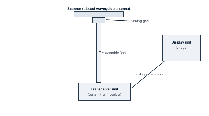
Main components
Transceiver / magnetron or solid-state transmitter
Generates the pulse; solid-state S-band transmitters are increasingly common, replacing magnetron units and removing the magnetron's limited service life as a maintenance item.
Antenna / scanner
A slotted waveguide array, physically longer than an equivalent X-band scanner for the same beamwidth because of the longer wavelength, which is part of why S-band units are usually the larger of the two radomes or open arrays on the mast.
Display / processor unit
Shares plotting, ARPA target tracking and often chart overlay functions with the ship's other radar and ECDIS through the integrated bridge system.
Waveguide or coaxial feed
Connects transceiver to antenna; condensation and corrosion inside waveguide runs are a recurring source of gradual signal loss.
Selection and sizing
- Range scale requirements for the vessel's typical trading area — deep-sea long-range detection favours S-band's weather penetration.
- Antenna length available on the mast, since S-band scanners are physically larger for comparable bearing accuracy.
- Solid-state versus magnetron transmitter, trading upfront cost against reduced long-term maintenance and no magnetron replacement.
- Integration requirements with existing ARPA, AIS overlay and ECDIS on the bridge.
Regulations and class requirements
SOLAS Chapter V requires ships of 3,000 gross tonnage and upwards to carry two radar systems capable of operating independently of each other, one of which must be a 9 GHz (X-band) set; the second is commonly S-band precisely to meet the intent of having two different frequency bands available. IMO performance standards for radar equipment cover both bands, and class surveys check that both sets remain operational and correctly interfaced with any integrated navigation system, not just present on the bridge.
Typical faults
| Fault | Consequence |
|---|---|
| Waveguide moisture ingress | Gradual loss of transmit power, showing up as reduced maximum range before the set fails outright. |
| Antenna motor or bearing wear | Scanner rotation slows or stalls, degrading picture update rate or stopping it entirely. |
| Magnetron end of life (older sets) | Falling output power and eventual loss of transmission, generally a scheduled replacement item. |
| Software or interface fault with ECDIS overlay | Radar remains usable standalone but loses integrated chart correlation, reducing situational awareness on the bridge. |
What to look for in a supplier
- Compatibility confirmed with the existing bridge integration standard, so the new set talks correctly to ECDIS and the other radar.
- Solid-state transmitter option where magnetron replacement cost and lead time is a concern.
- Type approval current against the applicable IMO radar performance standard.
- Spares and service support reachable in the vessel's normal trading ports, not only at the home port.
In heavy rain, switch to the S-band set rather than fighting X-band clutter controls — over-suppressing rain clutter on an X-band picture can hide a genuine small target as easily as the rain itself does.