What to check on a Conning Display / IBS.
A conning display is not a navigation system in its own right; it does not plot a route or calculate a fix. It is a presentation layer that gathers data already generated by the gyrocompass, speed log, rate-of-turn indicator, echo sounder, wind sensor, engine telegraph and thruster controls, and arranges it on a single screen at the position where the officer actually stands to manoeuvre the ship. An Integrated Bridge System (IBS) takes this further, tying conning, radar/ARPA, ECDIS, autopilot and alarm management into a common architecture so functions can…
What Sets This Type Apart
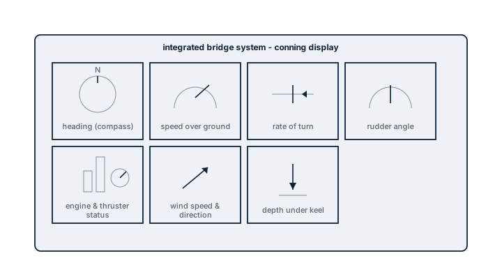
A conning display is not a navigation system in its own right; it does not plot a route or calculate a fix. It is a presentation layer that gathers data already generated by the gyrocompass, speed log, rate-of-turn indicator, echo sounder, wind sensor, engine telegraph and thruster controls, and arranges it on a single screen at the position where the officer actually stands to manoeuvre the ship. An Integrated Bridge System (IBS) takes this further, tying conning, radar/ARPA, ECDIS, autopilot and alarm management into a common architecture so functions can be cross-checked and, on some systems, controlled from more than one workstation. The value is entirely in reducing how many separate instruments the watchkeeper has to physically scan during a close-quarters situation.
Main Components
Display processing unit
Aggregates and formats incoming sensor data for presentation; on an IBS this processing is shared with or coordinated across the radar, ECDIS and alarm management processors rather than standing alone.
Sensor data interfaces
Standard serial data links from gyrocompass, GPS, log, echo sounder, wind sensor, rudder angle indicator, engine/thruster status, and rate-of-turn indicator; the conning display is only ever as reliable as the weakest of these feeds.
Display and workstation
A dedicated screen at the conning position, sometimes duplicated on the wings on larger or specialised vessels, with user-configurable page layouts for different phases of operation such as open water, pilotage or docking.
Alarm and status integration
On an IBS, sensor failures, out-of-range readings and system faults are surfaced through a common alarm philosophy rather than each subsystem alarming independently and inconsistently.
Selection and Sizing
The relevant decisions are architectural rather than mechanical.
- Standalone conning display versus full IBS integration, driven by vessel type and operational profile; a vessel doing frequent close-quarters manoeuvring such as ferries or offshore support benefits most from full integration.
- Number and placement of duplicate workstations needed for the vessel's bridge layout and manning philosophy.
- Compatibility of sensor data protocols with existing or planned equipment, since retrofitting a conning display onto older analogue instrumentation often needs signal conversion.
- Configurability of page layouts against the operator's standing bridge procedures, so the display supports rather than dictates watchkeeping practice.
Regulations and Class
There is no standalone SOLAS carriage requirement for a conning display as such, but where fitted as part of an IBS it must meet IMO performance standards for integrated bridge systems, including requirements for independent backup of individual functions should the integration fail. Class notations for integrated or centralised bridge operation, where a vessel is certified for reduced bridge manning, require the conning and alarm functions to meet specific redundancy and failure-mode criteria, verified at survey.
Typical Faults
| Fault | Cause | Consequence |
|---|---|---|
| Frozen or stale reading on one panel | Sensor data link fault not flagged clearly against an otherwise normal-looking display | Watchkeeper relies on outdated rate-of-turn or speed data without realising it |
| Conflicting data between conning display and individual repeaters | Calibration or offset mismatch between the sensor feed and the standalone instrument | Loss of confidence in the integrated display, reversion to manual cross-checking |
| Display blackout | Processing unit or power supply fault | Sudden loss of the consolidated picture during a manoeuvre, requiring immediate fallback to individual instruments |
| Alarm flooding | Poorly configured alarm thresholds inherited from default settings, not tuned to the vessel | Watchkeepers begin to disregard alarms, masking a genuine fault when it occurs |
What to Look for in a Supplier
- Clear documentation of which functions have independent backup instruments versus which depend entirely on the integrated display.
- Proven sensor interface compatibility list matched against the ship's actual gyrocompass, log and telegraph equipment.
- Configurable, not fixed, alarm thresholds, with support to tune them to the specific vessel during commissioning.
- Training and documentation adequate for watchkeepers to trust the system rather than defaulting back to individual instruments out of habit.
Never let a conning display or IBS become the only place a watchkeeper checks rudder angle or engine status; know where the standalone backup instrument is and glance at it occasionally, because an integrated screen that quietly stops updating one channel looks identical to one that is working.