OceanSphere
Engines

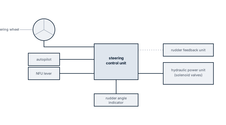
Steering Control System

critical IMO Required 75 models total
Electronic/electro-hydraulic steering control (NFU, FU, autopilot interface)
8000h
Service Interval
5 yr
Class Survey
20 yr
Typical Lifetime

Typical Manufacturers

Anschuetz Raytheon Kongsberg

8 manufacturers · 75 models

EMRI

24 ✓ 24 verified
SEM200 ✓ verified
Application
Autopilot & Track Control System
Common Failures & Inspection Points
  • Area: Rudder Angle Feedback Continuity & Potentiometer Wear
    Check: Verify potentiometer kit replacement intervals: RFC/RFU systems with sliding contact require replacement every 5 years maximum. RFC360-D Hall sensor versions have 10-year service life minimum. Test analog output signals (±12Vdc, ±15Vdc) from feedback units for noise and drift; confirm no mechanical wear in uni-ball links or belt drives on RFU/RFB units.
  • Area: Steering Response Time & Servo Control Unit Performance
    Check: Verify port-to-starboard rudder movement completes within 28-38 seconds per SOLAS requirements. Test RCU servo boxes (RCU10-440, RCU20-440, RCW10-440) for proportional/bang-bang control accuracy. Confirm power supply voltages at KSA control boards are stable (+/-12Vdc, +/-15Vdc, 100Vac). Check no hydraulic lock alarms on torque motors; verify coupling condition.
  • Area: WMS PLC System Integrity & Redundancy Configuration
    Check: Verify WMS (Work Mode Station) PLC firmware version matches documented baseline. Test RSR relay expansion boxes function correctly in multi-rudder systems. Confirm backup power supply (SAB.10/SAB10-230) voltage levels and capacitor condition. Verify hot standby redundancy switches operate without glitches; test fail-over response time.
  • Area: Bridge & Wheelhouse Indicator Display Accuracy
    Check: Test RIB511 and RIF511 rudder angle indicators for calibration accuracy against actual rudder position sensors. Verify analog output (1-0.1mA) continuity from indicators to autopilot control panels. Confirm SEM300 TFT display brightness (800 cd/m²) is within specification and visible from all bridge positions. Check all 4 control panel connections have consistent readouts; verify alarm annunciation.
  • Area: System Compatibility with Steering Gear Brands & Hydraulic Configuration
    Check: Identify installed steering gear brand (Mitsubishi, Kawasaki, ABB, Hatlapa, Hitachi) and confirm correct RCU/ACU model variant is installed. Verify hydraulic pump configuration matches system design: 3-pump systems use RCU10/RCW10 models, 4-pump LNG systems use RCU20-440. Test proportional vs. bang-bang control mode operation per gear manufacturer specifications. Inspect hydraulic hose condition and pressure relief valve settings.

Typ-universelle Inspektionspunkte fuer Steering Gear (verifiziert, 2026-06).

SEM300 ✓ verified
Application
Autopilot, Heading Control & Track Control System
Common Failures & Inspection Points
  • Area: Rudder Angle Feedback Continuity & Potentiometer Wear
    Check: Verify potentiometer kit replacement intervals: RFC/RFU systems with sliding contact require replacement every 5 years maximum. RFC360-D Hall sensor versions have 10-year service life minimum. Test analog output signals (±12Vdc, ±15Vdc) from feedback units for noise and drift; confirm no mechanical wear in uni-ball links or belt drives on RFU/RFB units.
  • Area: Steering Response Time & Servo Control Unit Performance
    Check: Verify port-to-starboard rudder movement completes within 28-38 seconds per SOLAS requirements. Test RCU servo boxes (RCU10-440, RCU20-440, RCW10-440) for proportional/bang-bang control accuracy. Confirm power supply voltages at KSA control boards are stable (+/-12Vdc, +/-15Vdc, 100Vac). Check no hydraulic lock alarms on torque motors; verify coupling condition.
  • Area: WMS PLC System Integrity & Redundancy Configuration
    Check: Verify WMS (Work Mode Station) PLC firmware version matches documented baseline. Test RSR relay expansion boxes function correctly in multi-rudder systems. Confirm backup power supply (SAB.10/SAB10-230) voltage levels and capacitor condition. Verify hot standby redundancy switches operate without glitches; test fail-over response time.
  • Area: Bridge & Wheelhouse Indicator Display Accuracy
    Check: Test RIB511 and RIF511 rudder angle indicators for calibration accuracy against actual rudder position sensors. Verify analog output (1-0.1mA) continuity from indicators to autopilot control panels. Confirm SEM300 TFT display brightness (800 cd/m²) is within specification and visible from all bridge positions. Check all 4 control panel connections have consistent readouts; verify alarm annunciation.
  • Area: System Compatibility with Steering Gear Brands & Hydraulic Configuration
    Check: Identify installed steering gear brand (Mitsubishi, Kawasaki, ABB, Hatlapa, Hitachi) and confirm correct RCU/ACU model variant is installed. Verify hydraulic pump configuration matches system design: 3-pump systems use RCU10/RCW10 models, 4-pump LNG systems use RCU20-440. Test proportional vs. bang-bang control mode operation per gear manufacturer specifications. Inspect hydraulic hose condition and pressure relief valve settings.

Typ-universelle Inspektionspunkte fuer Steering Gear (verifiziert, 2026-06).

RCU10-440 ✓ verified
Application
Rudder Control Unit (Servo Control Box) - Container Ships
Common Failures & Inspection Points
  • Area: Rudder Angle Feedback Continuity & Potentiometer Wear
    Check: Verify potentiometer kit replacement intervals: RFC/RFU systems with sliding contact require replacement every 5 years maximum. RFC360-D Hall sensor versions have 10-year service life minimum. Test analog output signals (±12Vdc, ±15Vdc) from feedback units for noise and drift; confirm no mechanical wear in uni-ball links or belt drives on RFU/RFB units.
  • Area: Steering Response Time & Servo Control Unit Performance
    Check: Verify port-to-starboard rudder movement completes within 28-38 seconds per SOLAS requirements. Test RCU servo boxes (RCU10-440, RCU20-440, RCW10-440) for proportional/bang-bang control accuracy. Confirm power supply voltages at KSA control boards are stable (+/-12Vdc, +/-15Vdc, 100Vac). Check no hydraulic lock alarms on torque motors; verify coupling condition.
  • Area: WMS PLC System Integrity & Redundancy Configuration
    Check: Verify WMS (Work Mode Station) PLC firmware version matches documented baseline. Test RSR relay expansion boxes function correctly in multi-rudder systems. Confirm backup power supply (SAB.10/SAB10-230) voltage levels and capacitor condition. Verify hot standby redundancy switches operate without glitches; test fail-over response time.
  • Area: Bridge & Wheelhouse Indicator Display Accuracy
    Check: Test RIB511 and RIF511 rudder angle indicators for calibration accuracy against actual rudder position sensors. Verify analog output (1-0.1mA) continuity from indicators to autopilot control panels. Confirm SEM300 TFT display brightness (800 cd/m²) is within specification and visible from all bridge positions. Check all 4 control panel connections have consistent readouts; verify alarm annunciation.
  • Area: System Compatibility with Steering Gear Brands & Hydraulic Configuration
    Check: Identify installed steering gear brand (Mitsubishi, Kawasaki, ABB, Hatlapa, Hitachi) and confirm correct RCU/ACU model variant is installed. Verify hydraulic pump configuration matches system design: 3-pump systems use RCU10/RCW10 models, 4-pump LNG systems use RCU20-440. Test proportional vs. bang-bang control mode operation per gear manufacturer specifications. Inspect hydraulic hose condition and pressure relief valve settings.

Typ-universelle Inspektionspunkte fuer Steering Gear (verifiziert, 2026-06).

RCU20-440 ✓ verified
Application
Rudder Control Unit (Servo Control Box) - LNG Ships
Common Failures & Inspection Points
  • Area: Rudder Angle Feedback Continuity & Potentiometer Wear
    Check: Verify potentiometer kit replacement intervals: RFC/RFU systems with sliding contact require replacement every 5 years maximum. RFC360-D Hall sensor versions have 10-year service life minimum. Test analog output signals (±12Vdc, ±15Vdc) from feedback units for noise and drift; confirm no mechanical wear in uni-ball links or belt drives on RFU/RFB units.
  • Area: Steering Response Time & Servo Control Unit Performance
    Check: Verify port-to-starboard rudder movement completes within 28-38 seconds per SOLAS requirements. Test RCU servo boxes (RCU10-440, RCU20-440, RCW10-440) for proportional/bang-bang control accuracy. Confirm power supply voltages at KSA control boards are stable (+/-12Vdc, +/-15Vdc, 100Vac). Check no hydraulic lock alarms on torque motors; verify coupling condition.
  • Area: WMS PLC System Integrity & Redundancy Configuration
    Check: Verify WMS (Work Mode Station) PLC firmware version matches documented baseline. Test RSR relay expansion boxes function correctly in multi-rudder systems. Confirm backup power supply (SAB.10/SAB10-230) voltage levels and capacitor condition. Verify hot standby redundancy switches operate without glitches; test fail-over response time.
  • Area: Bridge & Wheelhouse Indicator Display Accuracy
    Check: Test RIB511 and RIF511 rudder angle indicators for calibration accuracy against actual rudder position sensors. Verify analog output (1-0.1mA) continuity from indicators to autopilot control panels. Confirm SEM300 TFT display brightness (800 cd/m²) is within specification and visible from all bridge positions. Check all 4 control panel connections have consistent readouts; verify alarm annunciation.
  • Area: System Compatibility with Steering Gear Brands & Hydraulic Configuration
    Check: Identify installed steering gear brand (Mitsubishi, Kawasaki, ABB, Hatlapa, Hitachi) and confirm correct RCU/ACU model variant is installed. Verify hydraulic pump configuration matches system design: 3-pump systems use RCU10/RCW10 models, 4-pump LNG systems use RCU20-440. Test proportional vs. bang-bang control mode operation per gear manufacturer specifications. Inspect hydraulic hose condition and pressure relief valve settings.

Typ-universelle Inspektionspunkte fuer Steering Gear (verifiziert, 2026-06).

RCW10-440 ✓ verified
Application
Rudder Control Unit (Servo Control Box) - Hitachi Steering Gear
Common Failures & Inspection Points
  • Area: Rudder Angle Feedback Continuity & Potentiometer Wear
    Check: Verify potentiometer kit replacement intervals: RFC/RFU systems with sliding contact require replacement every 5 years maximum. RFC360-D Hall sensor versions have 10-year service life minimum. Test analog output signals (±12Vdc, ±15Vdc) from feedback units for noise and drift; confirm no mechanical wear in uni-ball links or belt drives on RFU/RFB units.
  • Area: Steering Response Time & Servo Control Unit Performance
    Check: Verify port-to-starboard rudder movement completes within 28-38 seconds per SOLAS requirements. Test RCU servo boxes (RCU10-440, RCU20-440, RCW10-440) for proportional/bang-bang control accuracy. Confirm power supply voltages at KSA control boards are stable (+/-12Vdc, +/-15Vdc, 100Vac). Check no hydraulic lock alarms on torque motors; verify coupling condition.
  • Area: WMS PLC System Integrity & Redundancy Configuration
    Check: Verify WMS (Work Mode Station) PLC firmware version matches documented baseline. Test RSR relay expansion boxes function correctly in multi-rudder systems. Confirm backup power supply (SAB.10/SAB10-230) voltage levels and capacitor condition. Verify hot standby redundancy switches operate without glitches; test fail-over response time.
  • Area: Bridge & Wheelhouse Indicator Display Accuracy
    Check: Test RIB511 and RIF511 rudder angle indicators for calibration accuracy against actual rudder position sensors. Verify analog output (1-0.1mA) continuity from indicators to autopilot control panels. Confirm SEM300 TFT display brightness (800 cd/m²) is within specification and visible from all bridge positions. Check all 4 control panel connections have consistent readouts; verify alarm annunciation.
  • Area: System Compatibility with Steering Gear Brands & Hydraulic Configuration
    Check: Identify installed steering gear brand (Mitsubishi, Kawasaki, ABB, Hatlapa, Hitachi) and confirm correct RCU/ACU model variant is installed. Verify hydraulic pump configuration matches system design: 3-pump systems use RCU10/RCW10 models, 4-pump LNG systems use RCU20-440. Test proportional vs. bang-bang control mode operation per gear manufacturer specifications. Inspect hydraulic hose condition and pressure relief valve settings.

Typ-universelle Inspektionspunkte fuer Steering Gear (verifiziert, 2026-06).

RCY10-440 ✓ verified
Application
Rudder Control Unit - Steering Control System
Common Failures & Inspection Points
  • Area: Rudder Angle Feedback Continuity & Potentiometer Wear
    Check: Verify potentiometer kit replacement intervals: RFC/RFU systems with sliding contact require replacement every 5 years maximum. RFC360-D Hall sensor versions have 10-year service life minimum. Test analog output signals (±12Vdc, ±15Vdc) from feedback units for noise and drift; confirm no mechanical wear in uni-ball links or belt drives on RFU/RFB units.
  • Area: Steering Response Time & Servo Control Unit Performance
    Check: Verify port-to-starboard rudder movement completes within 28-38 seconds per SOLAS requirements. Test RCU servo boxes (RCU10-440, RCU20-440, RCW10-440) for proportional/bang-bang control accuracy. Confirm power supply voltages at KSA control boards are stable (+/-12Vdc, +/-15Vdc, 100Vac). Check no hydraulic lock alarms on torque motors; verify coupling condition.
  • Area: WMS PLC System Integrity & Redundancy Configuration
    Check: Verify WMS (Work Mode Station) PLC firmware version matches documented baseline. Test RSR relay expansion boxes function correctly in multi-rudder systems. Confirm backup power supply (SAB.10/SAB10-230) voltage levels and capacitor condition. Verify hot standby redundancy switches operate without glitches; test fail-over response time.
  • Area: Bridge & Wheelhouse Indicator Display Accuracy
    Check: Test RIB511 and RIF511 rudder angle indicators for calibration accuracy against actual rudder position sensors. Verify analog output (1-0.1mA) continuity from indicators to autopilot control panels. Confirm SEM300 TFT display brightness (800 cd/m²) is within specification and visible from all bridge positions. Check all 4 control panel connections have consistent readouts; verify alarm annunciation.
  • Area: System Compatibility with Steering Gear Brands & Hydraulic Configuration
    Check: Identify installed steering gear brand (Mitsubishi, Kawasaki, ABB, Hatlapa, Hitachi) and confirm correct RCU/ACU model variant is installed. Verify hydraulic pump configuration matches system design: 3-pump systems use RCU10/RCW10 models, 4-pump LNG systems use RCU20-440. Test proportional vs. bang-bang control mode operation per gear manufacturer specifications. Inspect hydraulic hose condition and pressure relief valve settings.

Typ-universelle Inspektionspunkte fuer Steering Gear (verifiziert, 2026-06).

RFU (Original) ✓ verified
Application
Rudder Feedback Unit - Metal Rudder Rod Systems
Common Failures & Inspection Points
  • Area: Rudder Angle Feedback Continuity & Potentiometer Wear
    Check: Verify potentiometer kit replacement intervals: RFC/RFU systems with sliding contact require replacement every 5 years maximum. RFC360-D Hall sensor versions have 10-year service life minimum. Test analog output signals (±12Vdc, ±15Vdc) from feedback units for noise and drift; confirm no mechanical wear in uni-ball links or belt drives on RFU/RFB units.
  • Area: Steering Response Time & Servo Control Unit Performance
    Check: Verify port-to-starboard rudder movement completes within 28-38 seconds per SOLAS requirements. Test RCU servo boxes (RCU10-440, RCU20-440, RCW10-440) for proportional/bang-bang control accuracy. Confirm power supply voltages at KSA control boards are stable (+/-12Vdc, +/-15Vdc, 100Vac). Check no hydraulic lock alarms on torque motors; verify coupling condition.
  • Area: WMS PLC System Integrity & Redundancy Configuration
    Check: Verify WMS (Work Mode Station) PLC firmware version matches documented baseline. Test RSR relay expansion boxes function correctly in multi-rudder systems. Confirm backup power supply (SAB.10/SAB10-230) voltage levels and capacitor condition. Verify hot standby redundancy switches operate without glitches; test fail-over response time.
  • Area: Bridge & Wheelhouse Indicator Display Accuracy
    Check: Test RIB511 and RIF511 rudder angle indicators for calibration accuracy against actual rudder position sensors. Verify analog output (1-0.1mA) continuity from indicators to autopilot control panels. Confirm SEM300 TFT display brightness (800 cd/m²) is within specification and visible from all bridge positions. Check all 4 control panel connections have consistent readouts; verify alarm annunciation.
  • Area: System Compatibility with Steering Gear Brands & Hydraulic Configuration
    Check: Identify installed steering gear brand (Mitsubishi, Kawasaki, ABB, Hatlapa, Hitachi) and confirm correct RCU/ACU model variant is installed. Verify hydraulic pump configuration matches system design: 3-pump systems use RCU10/RCW10 models, 4-pump LNG systems use RCU20-440. Test proportional vs. bang-bang control mode operation per gear manufacturer specifications. Inspect hydraulic hose condition and pressure relief valve settings.

Typ-universelle Inspektionspunkte fuer Steering Gear (verifiziert, 2026-06).

RFB360 / RFB ✓ verified
Application
Rudder Feedback Unit - Belt Drive Azimuth Systems
Common Failures & Inspection Points
  • Area: Rudder Angle Feedback Continuity & Potentiometer Wear
    Check: Verify potentiometer kit replacement intervals: RFC/RFU systems with sliding contact require replacement every 5 years maximum. RFC360-D Hall sensor versions have 10-year service life minimum. Test analog output signals (±12Vdc, ±15Vdc) from feedback units for noise and drift; confirm no mechanical wear in uni-ball links or belt drives on RFU/RFB units.
  • Area: Steering Response Time & Servo Control Unit Performance
    Check: Verify port-to-starboard rudder movement completes within 28-38 seconds per SOLAS requirements. Test RCU servo boxes (RCU10-440, RCU20-440, RCW10-440) for proportional/bang-bang control accuracy. Confirm power supply voltages at KSA control boards are stable (+/-12Vdc, +/-15Vdc, 100Vac). Check no hydraulic lock alarms on torque motors; verify coupling condition.
  • Area: WMS PLC System Integrity & Redundancy Configuration
    Check: Verify WMS (Work Mode Station) PLC firmware version matches documented baseline. Test RSR relay expansion boxes function correctly in multi-rudder systems. Confirm backup power supply (SAB.10/SAB10-230) voltage levels and capacitor condition. Verify hot standby redundancy switches operate without glitches; test fail-over response time.
  • Area: Bridge & Wheelhouse Indicator Display Accuracy
    Check: Test RIB511 and RIF511 rudder angle indicators for calibration accuracy against actual rudder position sensors. Verify analog output (1-0.1mA) continuity from indicators to autopilot control panels. Confirm SEM300 TFT display brightness (800 cd/m²) is within specification and visible from all bridge positions. Check all 4 control panel connections have consistent readouts; verify alarm annunciation.
  • Area: System Compatibility with Steering Gear Brands & Hydraulic Configuration
    Check: Identify installed steering gear brand (Mitsubishi, Kawasaki, ABB, Hatlapa, Hitachi) and confirm correct RCU/ACU model variant is installed. Verify hydraulic pump configuration matches system design: 3-pump systems use RCU10/RCW10 models, 4-pump LNG systems use RCU20-440. Test proportional vs. bang-bang control mode operation per gear manufacturer specifications. Inspect hydraulic hose condition and pressure relief valve settings.

Typ-universelle Inspektionspunkte fuer Steering Gear (verifiziert, 2026-06).

RFC360-D ✓ verified
Application
Digital Potentiometer Kit for RFB360 Azimuth Feedback
Common Failures & Inspection Points
  • Area: Rudder Angle Feedback Continuity & Potentiometer Wear
    Check: Verify potentiometer kit replacement intervals: RFC/RFU systems with sliding contact require replacement every 5 years maximum. RFC360-D Hall sensor versions have 10-year service life minimum. Test analog output signals (±12Vdc, ±15Vdc) from feedback units for noise and drift; confirm no mechanical wear in uni-ball links or belt drives on RFU/RFB units.
  • Area: Steering Response Time & Servo Control Unit Performance
    Check: Verify port-to-starboard rudder movement completes within 28-38 seconds per SOLAS requirements. Test RCU servo boxes (RCU10-440, RCU20-440, RCW10-440) for proportional/bang-bang control accuracy. Confirm power supply voltages at KSA control boards are stable (+/-12Vdc, +/-15Vdc, 100Vac). Check no hydraulic lock alarms on torque motors; verify coupling condition.
  • Area: WMS PLC System Integrity & Redundancy Configuration
    Check: Verify WMS (Work Mode Station) PLC firmware version matches documented baseline. Test RSR relay expansion boxes function correctly in multi-rudder systems. Confirm backup power supply (SAB.10/SAB10-230) voltage levels and capacitor condition. Verify hot standby redundancy switches operate without glitches; test fail-over response time.
  • Area: Bridge & Wheelhouse Indicator Display Accuracy
    Check: Test RIB511 and RIF511 rudder angle indicators for calibration accuracy against actual rudder position sensors. Verify analog output (1-0.1mA) continuity from indicators to autopilot control panels. Confirm SEM300 TFT display brightness (800 cd/m²) is within specification and visible from all bridge positions. Check all 4 control panel connections have consistent readouts; verify alarm annunciation.
  • Area: System Compatibility with Steering Gear Brands & Hydraulic Configuration
    Check: Identify installed steering gear brand (Mitsubishi, Kawasaki, ABB, Hatlapa, Hitachi) and confirm correct RCU/ACU model variant is installed. Verify hydraulic pump configuration matches system design: 3-pump systems use RCU10/RCW10 models, 4-pump LNG systems use RCU20-440. Test proportional vs. bang-bang control mode operation per gear manufacturer specifications. Inspect hydraulic hose condition and pressure relief valve settings.

Typ-universelle Inspektionspunkte fuer Steering Gear (verifiziert, 2026-06).

RFC33 ✓ verified
Application
Potentiometer Kit for Rudder Feedback Unit
Common Failures & Inspection Points
  • Area: Rudder Angle Feedback Continuity & Potentiometer Wear
    Check: Verify potentiometer kit replacement intervals: RFC/RFU systems with sliding contact require replacement every 5 years maximum. RFC360-D Hall sensor versions have 10-year service life minimum. Test analog output signals (±12Vdc, ±15Vdc) from feedback units for noise and drift; confirm no mechanical wear in uni-ball links or belt drives on RFU/RFB units.
  • Area: Steering Response Time & Servo Control Unit Performance
    Check: Verify port-to-starboard rudder movement completes within 28-38 seconds per SOLAS requirements. Test RCU servo boxes (RCU10-440, RCU20-440, RCW10-440) for proportional/bang-bang control accuracy. Confirm power supply voltages at KSA control boards are stable (+/-12Vdc, +/-15Vdc, 100Vac). Check no hydraulic lock alarms on torque motors; verify coupling condition.
  • Area: WMS PLC System Integrity & Redundancy Configuration
    Check: Verify WMS (Work Mode Station) PLC firmware version matches documented baseline. Test RSR relay expansion boxes function correctly in multi-rudder systems. Confirm backup power supply (SAB.10/SAB10-230) voltage levels and capacitor condition. Verify hot standby redundancy switches operate without glitches; test fail-over response time.
  • Area: Bridge & Wheelhouse Indicator Display Accuracy
    Check: Test RIB511 and RIF511 rudder angle indicators for calibration accuracy against actual rudder position sensors. Verify analog output (1-0.1mA) continuity from indicators to autopilot control panels. Confirm SEM300 TFT display brightness (800 cd/m²) is within specification and visible from all bridge positions. Check all 4 control panel connections have consistent readouts; verify alarm annunciation.
  • Area: System Compatibility with Steering Gear Brands & Hydraulic Configuration
    Check: Identify installed steering gear brand (Mitsubishi, Kawasaki, ABB, Hatlapa, Hitachi) and confirm correct RCU/ACU model variant is installed. Verify hydraulic pump configuration matches system design: 3-pump systems use RCU10/RCW10 models, 4-pump LNG systems use RCU20-440. Test proportional vs. bang-bang control mode operation per gear manufacturer specifications. Inspect hydraulic hose condition and pressure relief valve settings.

Typ-universelle Inspektionspunkte fuer Steering Gear (verifiziert, 2026-06).

RFU32 ✓ verified
Application
Potentiometer Kit for Rudder Feedback Unit
Common Failures & Inspection Points
  • Area: Rudder Angle Feedback Continuity & Potentiometer Wear
    Check: Verify potentiometer kit replacement intervals: RFC/RFU systems with sliding contact require replacement every 5 years maximum. RFC360-D Hall sensor versions have 10-year service life minimum. Test analog output signals (±12Vdc, ±15Vdc) from feedback units for noise and drift; confirm no mechanical wear in uni-ball links or belt drives on RFU/RFB units.
  • Area: Steering Response Time & Servo Control Unit Performance
    Check: Verify port-to-starboard rudder movement completes within 28-38 seconds per SOLAS requirements. Test RCU servo boxes (RCU10-440, RCU20-440, RCW10-440) for proportional/bang-bang control accuracy. Confirm power supply voltages at KSA control boards are stable (+/-12Vdc, +/-15Vdc, 100Vac). Check no hydraulic lock alarms on torque motors; verify coupling condition.
  • Area: WMS PLC System Integrity & Redundancy Configuration
    Check: Verify WMS (Work Mode Station) PLC firmware version matches documented baseline. Test RSR relay expansion boxes function correctly in multi-rudder systems. Confirm backup power supply (SAB.10/SAB10-230) voltage levels and capacitor condition. Verify hot standby redundancy switches operate without glitches; test fail-over response time.
  • Area: Bridge & Wheelhouse Indicator Display Accuracy
    Check: Test RIB511 and RIF511 rudder angle indicators for calibration accuracy against actual rudder position sensors. Verify analog output (1-0.1mA) continuity from indicators to autopilot control panels. Confirm SEM300 TFT display brightness (800 cd/m²) is within specification and visible from all bridge positions. Check all 4 control panel connections have consistent readouts; verify alarm annunciation.
  • Area: System Compatibility with Steering Gear Brands & Hydraulic Configuration
    Check: Identify installed steering gear brand (Mitsubishi, Kawasaki, ABB, Hatlapa, Hitachi) and confirm correct RCU/ACU model variant is installed. Verify hydraulic pump configuration matches system design: 3-pump systems use RCU10/RCW10 models, 4-pump LNG systems use RCU20-440. Test proportional vs. bang-bang control mode operation per gear manufacturer specifications. Inspect hydraulic hose condition and pressure relief valve settings.

Typ-universelle Inspektionspunkte fuer Steering Gear (verifiziert, 2026-06).

WMS (Work Mode Station) ✓ verified
Application
Central PLC Steering Computer & System Control
Common Failures & Inspection Points
  • Area: Rudder Angle Feedback Continuity & Potentiometer Wear
    Check: Verify potentiometer kit replacement intervals: RFC/RFU systems with sliding contact require replacement every 5 years maximum. RFC360-D Hall sensor versions have 10-year service life minimum. Test analog output signals (±12Vdc, ±15Vdc) from feedback units for noise and drift; confirm no mechanical wear in uni-ball links or belt drives on RFU/RFB units.
  • Area: Steering Response Time & Servo Control Unit Performance
    Check: Verify port-to-starboard rudder movement completes within 28-38 seconds per SOLAS requirements. Test RCU servo boxes (RCU10-440, RCU20-440, RCW10-440) for proportional/bang-bang control accuracy. Confirm power supply voltages at KSA control boards are stable (+/-12Vdc, +/-15Vdc, 100Vac). Check no hydraulic lock alarms on torque motors; verify coupling condition.
  • Area: WMS PLC System Integrity & Redundancy Configuration
    Check: Verify WMS (Work Mode Station) PLC firmware version matches documented baseline. Test RSR relay expansion boxes function correctly in multi-rudder systems. Confirm backup power supply (SAB.10/SAB10-230) voltage levels and capacitor condition. Verify hot standby redundancy switches operate without glitches; test fail-over response time.
  • Area: Bridge & Wheelhouse Indicator Display Accuracy
    Check: Test RIB511 and RIF511 rudder angle indicators for calibration accuracy against actual rudder position sensors. Verify analog output (1-0.1mA) continuity from indicators to autopilot control panels. Confirm SEM300 TFT display brightness (800 cd/m²) is within specification and visible from all bridge positions. Check all 4 control panel connections have consistent readouts; verify alarm annunciation.
  • Area: System Compatibility with Steering Gear Brands & Hydraulic Configuration
    Check: Identify installed steering gear brand (Mitsubishi, Kawasaki, ABB, Hatlapa, Hitachi) and confirm correct RCU/ACU model variant is installed. Verify hydraulic pump configuration matches system design: 3-pump systems use RCU10/RCW10 models, 4-pump LNG systems use RCU20-440. Test proportional vs. bang-bang control mode operation per gear manufacturer specifications. Inspect hydraulic hose condition and pressure relief valve settings.

Typ-universelle Inspektionspunkte fuer Steering Gear (verifiziert, 2026-06).

ACU (Analog Servo Unit) ✓ verified
Application
Rudder Control Unit - ABB/Hatlapa Steering Gears
Common Failures & Inspection Points
  • Area: Rudder Angle Feedback Continuity & Potentiometer Wear
    Check: Verify potentiometer kit replacement intervals: RFC/RFU systems with sliding contact require replacement every 5 years maximum. RFC360-D Hall sensor versions have 10-year service life minimum. Test analog output signals (±12Vdc, ±15Vdc) from feedback units for noise and drift; confirm no mechanical wear in uni-ball links or belt drives on RFU/RFB units.
  • Area: Steering Response Time & Servo Control Unit Performance
    Check: Verify port-to-starboard rudder movement completes within 28-38 seconds per SOLAS requirements. Test RCU servo boxes (RCU10-440, RCU20-440, RCW10-440) for proportional/bang-bang control accuracy. Confirm power supply voltages at KSA control boards are stable (+/-12Vdc, +/-15Vdc, 100Vac). Check no hydraulic lock alarms on torque motors; verify coupling condition.
  • Area: WMS PLC System Integrity & Redundancy Configuration
    Check: Verify WMS (Work Mode Station) PLC firmware version matches documented baseline. Test RSR relay expansion boxes function correctly in multi-rudder systems. Confirm backup power supply (SAB.10/SAB10-230) voltage levels and capacitor condition. Verify hot standby redundancy switches operate without glitches; test fail-over response time.
  • Area: Bridge & Wheelhouse Indicator Display Accuracy
    Check: Test RIB511 and RIF511 rudder angle indicators for calibration accuracy against actual rudder position sensors. Verify analog output (1-0.1mA) continuity from indicators to autopilot control panels. Confirm SEM300 TFT display brightness (800 cd/m²) is within specification and visible from all bridge positions. Check all 4 control panel connections have consistent readouts; verify alarm annunciation.
  • Area: System Compatibility with Steering Gear Brands & Hydraulic Configuration
    Check: Identify installed steering gear brand (Mitsubishi, Kawasaki, ABB, Hatlapa, Hitachi) and confirm correct RCU/ACU model variant is installed. Verify hydraulic pump configuration matches system design: 3-pump systems use RCU10/RCW10 models, 4-pump LNG systems use RCU20-440. Test proportional vs. bang-bang control mode operation per gear manufacturer specifications. Inspect hydraulic hose condition and pressure relief valve settings.

Typ-universelle Inspektionspunkte fuer Steering Gear (verifiziert, 2026-06).

KSA11 ✓ verified
Application
Control Board - Steering Control System
Common Failures & Inspection Points
  • Area: Rudder Angle Feedback Continuity & Potentiometer Wear
    Check: Verify potentiometer kit replacement intervals: RFC/RFU systems with sliding contact require replacement every 5 years maximum. RFC360-D Hall sensor versions have 10-year service life minimum. Test analog output signals (±12Vdc, ±15Vdc) from feedback units for noise and drift; confirm no mechanical wear in uni-ball links or belt drives on RFU/RFB units.
  • Area: Steering Response Time & Servo Control Unit Performance
    Check: Verify port-to-starboard rudder movement completes within 28-38 seconds per SOLAS requirements. Test RCU servo boxes (RCU10-440, RCU20-440, RCW10-440) for proportional/bang-bang control accuracy. Confirm power supply voltages at KSA control boards are stable (+/-12Vdc, +/-15Vdc, 100Vac). Check no hydraulic lock alarms on torque motors; verify coupling condition.
  • Area: WMS PLC System Integrity & Redundancy Configuration
    Check: Verify WMS (Work Mode Station) PLC firmware version matches documented baseline. Test RSR relay expansion boxes function correctly in multi-rudder systems. Confirm backup power supply (SAB.10/SAB10-230) voltage levels and capacitor condition. Verify hot standby redundancy switches operate without glitches; test fail-over response time.
  • Area: Bridge & Wheelhouse Indicator Display Accuracy
    Check: Test RIB511 and RIF511 rudder angle indicators for calibration accuracy against actual rudder position sensors. Verify analog output (1-0.1mA) continuity from indicators to autopilot control panels. Confirm SEM300 TFT display brightness (800 cd/m²) is within specification and visible from all bridge positions. Check all 4 control panel connections have consistent readouts; verify alarm annunciation.
  • Area: System Compatibility with Steering Gear Brands & Hydraulic Configuration
    Check: Identify installed steering gear brand (Mitsubishi, Kawasaki, ABB, Hatlapa, Hitachi) and confirm correct RCU/ACU model variant is installed. Verify hydraulic pump configuration matches system design: 3-pump systems use RCU10/RCW10 models, 4-pump LNG systems use RCU20-440. Test proportional vs. bang-bang control mode operation per gear manufacturer specifications. Inspect hydraulic hose condition and pressure relief valve settings.

Typ-universelle Inspektionspunkte fuer Steering Gear (verifiziert, 2026-06).

KSA12 ✓ verified
Application
Control Board - Steering Control System
Common Failures & Inspection Points
  • Area: Rudder Angle Feedback Continuity & Potentiometer Wear
    Check: Verify potentiometer kit replacement intervals: RFC/RFU systems with sliding contact require replacement every 5 years maximum. RFC360-D Hall sensor versions have 10-year service life minimum. Test analog output signals (±12Vdc, ±15Vdc) from feedback units for noise and drift; confirm no mechanical wear in uni-ball links or belt drives on RFU/RFB units.
  • Area: Steering Response Time & Servo Control Unit Performance
    Check: Verify port-to-starboard rudder movement completes within 28-38 seconds per SOLAS requirements. Test RCU servo boxes (RCU10-440, RCU20-440, RCW10-440) for proportional/bang-bang control accuracy. Confirm power supply voltages at KSA control boards are stable (+/-12Vdc, +/-15Vdc, 100Vac). Check no hydraulic lock alarms on torque motors; verify coupling condition.
  • Area: WMS PLC System Integrity & Redundancy Configuration
    Check: Verify WMS (Work Mode Station) PLC firmware version matches documented baseline. Test RSR relay expansion boxes function correctly in multi-rudder systems. Confirm backup power supply (SAB.10/SAB10-230) voltage levels and capacitor condition. Verify hot standby redundancy switches operate without glitches; test fail-over response time.
  • Area: Bridge & Wheelhouse Indicator Display Accuracy
    Check: Test RIB511 and RIF511 rudder angle indicators for calibration accuracy against actual rudder position sensors. Verify analog output (1-0.1mA) continuity from indicators to autopilot control panels. Confirm SEM300 TFT display brightness (800 cd/m²) is within specification and visible from all bridge positions. Check all 4 control panel connections have consistent readouts; verify alarm annunciation.
  • Area: System Compatibility with Steering Gear Brands & Hydraulic Configuration
    Check: Identify installed steering gear brand (Mitsubishi, Kawasaki, ABB, Hatlapa, Hitachi) and confirm correct RCU/ACU model variant is installed. Verify hydraulic pump configuration matches system design: 3-pump systems use RCU10/RCW10 models, 4-pump LNG systems use RCU20-440. Test proportional vs. bang-bang control mode operation per gear manufacturer specifications. Inspect hydraulic hose condition and pressure relief valve settings.

Typ-universelle Inspektionspunkte fuer Steering Gear (verifiziert, 2026-06).

SAB.10 / SAB10-230 ✓ verified
Application
Power Supply Unit & Rudder Angle Amplifier
Common Failures & Inspection Points
  • Area: Rudder Angle Feedback Continuity & Potentiometer Wear
    Check: Verify potentiometer kit replacement intervals: RFC/RFU systems with sliding contact require replacement every 5 years maximum. RFC360-D Hall sensor versions have 10-year service life minimum. Test analog output signals (±12Vdc, ±15Vdc) from feedback units for noise and drift; confirm no mechanical wear in uni-ball links or belt drives on RFU/RFB units.
  • Area: Steering Response Time & Servo Control Unit Performance
    Check: Verify port-to-starboard rudder movement completes within 28-38 seconds per SOLAS requirements. Test RCU servo boxes (RCU10-440, RCU20-440, RCW10-440) for proportional/bang-bang control accuracy. Confirm power supply voltages at KSA control boards are stable (+/-12Vdc, +/-15Vdc, 100Vac). Check no hydraulic lock alarms on torque motors; verify coupling condition.
  • Area: WMS PLC System Integrity & Redundancy Configuration
    Check: Verify WMS (Work Mode Station) PLC firmware version matches documented baseline. Test RSR relay expansion boxes function correctly in multi-rudder systems. Confirm backup power supply (SAB.10/SAB10-230) voltage levels and capacitor condition. Verify hot standby redundancy switches operate without glitches; test fail-over response time.
  • Area: Bridge & Wheelhouse Indicator Display Accuracy
    Check: Test RIB511 and RIF511 rudder angle indicators for calibration accuracy against actual rudder position sensors. Verify analog output (1-0.1mA) continuity from indicators to autopilot control panels. Confirm SEM300 TFT display brightness (800 cd/m²) is within specification and visible from all bridge positions. Check all 4 control panel connections have consistent readouts; verify alarm annunciation.
  • Area: System Compatibility with Steering Gear Brands & Hydraulic Configuration
    Check: Identify installed steering gear brand (Mitsubishi, Kawasaki, ABB, Hatlapa, Hitachi) and confirm correct RCU/ACU model variant is installed. Verify hydraulic pump configuration matches system design: 3-pump systems use RCU10/RCW10 models, 4-pump LNG systems use RCU20-440. Test proportional vs. bang-bang control mode operation per gear manufacturer specifications. Inspect hydraulic hose condition and pressure relief valve settings.

Typ-universelle Inspektionspunkte fuer Steering Gear (verifiziert, 2026-06).

RIB511 ✓ verified
Application
Rudder Angle Indicator Panel
Common Failures & Inspection Points
  • Area: Rudder Angle Feedback Continuity & Potentiometer Wear
    Check: Verify potentiometer kit replacement intervals: RFC/RFU systems with sliding contact require replacement every 5 years maximum. RFC360-D Hall sensor versions have 10-year service life minimum. Test analog output signals (±12Vdc, ±15Vdc) from feedback units for noise and drift; confirm no mechanical wear in uni-ball links or belt drives on RFU/RFB units.
  • Area: Steering Response Time & Servo Control Unit Performance
    Check: Verify port-to-starboard rudder movement completes within 28-38 seconds per SOLAS requirements. Test RCU servo boxes (RCU10-440, RCU20-440, RCW10-440) for proportional/bang-bang control accuracy. Confirm power supply voltages at KSA control boards are stable (+/-12Vdc, +/-15Vdc, 100Vac). Check no hydraulic lock alarms on torque motors; verify coupling condition.
  • Area: WMS PLC System Integrity & Redundancy Configuration
    Check: Verify WMS (Work Mode Station) PLC firmware version matches documented baseline. Test RSR relay expansion boxes function correctly in multi-rudder systems. Confirm backup power supply (SAB.10/SAB10-230) voltage levels and capacitor condition. Verify hot standby redundancy switches operate without glitches; test fail-over response time.
  • Area: Bridge & Wheelhouse Indicator Display Accuracy
    Check: Test RIB511 and RIF511 rudder angle indicators for calibration accuracy against actual rudder position sensors. Verify analog output (1-0.1mA) continuity from indicators to autopilot control panels. Confirm SEM300 TFT display brightness (800 cd/m²) is within specification and visible from all bridge positions. Check all 4 control panel connections have consistent readouts; verify alarm annunciation.
  • Area: System Compatibility with Steering Gear Brands & Hydraulic Configuration
    Check: Identify installed steering gear brand (Mitsubishi, Kawasaki, ABB, Hatlapa, Hitachi) and confirm correct RCU/ACU model variant is installed. Verify hydraulic pump configuration matches system design: 3-pump systems use RCU10/RCW10 models, 4-pump LNG systems use RCU20-440. Test proportional vs. bang-bang control mode operation per gear manufacturer specifications. Inspect hydraulic hose condition and pressure relief valve settings.

Typ-universelle Inspektionspunkte fuer Steering Gear (verifiziert, 2026-06).

RIF511-WP ✓ verified
Application
Rudder Angle Indicator Panel
Common Failures & Inspection Points
  • Area: Rudder Angle Feedback Continuity & Potentiometer Wear
    Check: Verify potentiometer kit replacement intervals: RFC/RFU systems with sliding contact require replacement every 5 years maximum. RFC360-D Hall sensor versions have 10-year service life minimum. Test analog output signals (±12Vdc, ±15Vdc) from feedback units for noise and drift; confirm no mechanical wear in uni-ball links or belt drives on RFU/RFB units.
  • Area: Steering Response Time & Servo Control Unit Performance
    Check: Verify port-to-starboard rudder movement completes within 28-38 seconds per SOLAS requirements. Test RCU servo boxes (RCU10-440, RCU20-440, RCW10-440) for proportional/bang-bang control accuracy. Confirm power supply voltages at KSA control boards are stable (+/-12Vdc, +/-15Vdc, 100Vac). Check no hydraulic lock alarms on torque motors; verify coupling condition.
  • Area: WMS PLC System Integrity & Redundancy Configuration
    Check: Verify WMS (Work Mode Station) PLC firmware version matches documented baseline. Test RSR relay expansion boxes function correctly in multi-rudder systems. Confirm backup power supply (SAB.10/SAB10-230) voltage levels and capacitor condition. Verify hot standby redundancy switches operate without glitches; test fail-over response time.
  • Area: Bridge & Wheelhouse Indicator Display Accuracy
    Check: Test RIB511 and RIF511 rudder angle indicators for calibration accuracy against actual rudder position sensors. Verify analog output (1-0.1mA) continuity from indicators to autopilot control panels. Confirm SEM300 TFT display brightness (800 cd/m²) is within specification and visible from all bridge positions. Check all 4 control panel connections have consistent readouts; verify alarm annunciation.
  • Area: System Compatibility with Steering Gear Brands & Hydraulic Configuration
    Check: Identify installed steering gear brand (Mitsubishi, Kawasaki, ABB, Hatlapa, Hitachi) and confirm correct RCU/ACU model variant is installed. Verify hydraulic pump configuration matches system design: 3-pump systems use RCU10/RCW10 models, 4-pump LNG systems use RCU20-440. Test proportional vs. bang-bang control mode operation per gear manufacturer specifications. Inspect hydraulic hose condition and pressure relief valve settings.

Typ-universelle Inspektionspunkte fuer Steering Gear (verifiziert, 2026-06).

RSR Units ✓ verified
Application
Relay Expansion Boxes - System Expansion
Common Failures & Inspection Points
  • Area: Rudder Angle Feedback Continuity & Potentiometer Wear
    Check: Verify potentiometer kit replacement intervals: RFC/RFU systems with sliding contact require replacement every 5 years maximum. RFC360-D Hall sensor versions have 10-year service life minimum. Test analog output signals (±12Vdc, ±15Vdc) from feedback units for noise and drift; confirm no mechanical wear in uni-ball links or belt drives on RFU/RFB units.
  • Area: Steering Response Time & Servo Control Unit Performance
    Check: Verify port-to-starboard rudder movement completes within 28-38 seconds per SOLAS requirements. Test RCU servo boxes (RCU10-440, RCU20-440, RCW10-440) for proportional/bang-bang control accuracy. Confirm power supply voltages at KSA control boards are stable (+/-12Vdc, +/-15Vdc, 100Vac). Check no hydraulic lock alarms on torque motors; verify coupling condition.
  • Area: WMS PLC System Integrity & Redundancy Configuration
    Check: Verify WMS (Work Mode Station) PLC firmware version matches documented baseline. Test RSR relay expansion boxes function correctly in multi-rudder systems. Confirm backup power supply (SAB.10/SAB10-230) voltage levels and capacitor condition. Verify hot standby redundancy switches operate without glitches; test fail-over response time.
  • Area: Bridge & Wheelhouse Indicator Display Accuracy
    Check: Test RIB511 and RIF511 rudder angle indicators for calibration accuracy against actual rudder position sensors. Verify analog output (1-0.1mA) continuity from indicators to autopilot control panels. Confirm SEM300 TFT display brightness (800 cd/m²) is within specification and visible from all bridge positions. Check all 4 control panel connections have consistent readouts; verify alarm annunciation.
  • Area: System Compatibility with Steering Gear Brands & Hydraulic Configuration
    Check: Identify installed steering gear brand (Mitsubishi, Kawasaki, ABB, Hatlapa, Hitachi) and confirm correct RCU/ACU model variant is installed. Verify hydraulic pump configuration matches system design: 3-pump systems use RCU10/RCW10 models, 4-pump LNG systems use RCU20-440. Test proportional vs. bang-bang control mode operation per gear manufacturer specifications. Inspect hydraulic hose condition and pressure relief valve settings.

Typ-universelle Inspektionspunkte fuer Steering Gear (verifiziert, 2026-06).

Steering Control System (SCS) ✓ verified
Application
Complete Modular Steering Control Platform
Common Failures & Inspection Points
  • Area: Rudder Angle Feedback Continuity & Potentiometer Wear
    Check: Verify potentiometer kit replacement intervals: RFC/RFU systems with sliding contact require replacement every 5 years maximum. RFC360-D Hall sensor versions have 10-year service life minimum. Test analog output signals (±12Vdc, ±15Vdc) from feedback units for noise and drift; confirm no mechanical wear in uni-ball links or belt drives on RFU/RFB units.
  • Area: Steering Response Time & Servo Control Unit Performance
    Check: Verify port-to-starboard rudder movement completes within 28-38 seconds per SOLAS requirements. Test RCU servo boxes (RCU10-440, RCU20-440, RCW10-440) for proportional/bang-bang control accuracy. Confirm power supply voltages at KSA control boards are stable (+/-12Vdc, +/-15Vdc, 100Vac). Check no hydraulic lock alarms on torque motors; verify coupling condition.
  • Area: WMS PLC System Integrity & Redundancy Configuration
    Check: Verify WMS (Work Mode Station) PLC firmware version matches documented baseline. Test RSR relay expansion boxes function correctly in multi-rudder systems. Confirm backup power supply (SAB.10/SAB10-230) voltage levels and capacitor condition. Verify hot standby redundancy switches operate without glitches; test fail-over response time.
  • Area: Bridge & Wheelhouse Indicator Display Accuracy
    Check: Test RIB511 and RIF511 rudder angle indicators for calibration accuracy against actual rudder position sensors. Verify analog output (1-0.1mA) continuity from indicators to autopilot control panels. Confirm SEM300 TFT display brightness (800 cd/m²) is within specification and visible from all bridge positions. Check all 4 control panel connections have consistent readouts; verify alarm annunciation.
  • Area: System Compatibility with Steering Gear Brands & Hydraulic Configuration
    Check: Identify installed steering gear brand (Mitsubishi, Kawasaki, ABB, Hatlapa, Hitachi) and confirm correct RCU/ACU model variant is installed. Verify hydraulic pump configuration matches system design: 3-pump systems use RCU10/RCW10 models, 4-pump LNG systems use RCU20-440. Test proportional vs. bang-bang control mode operation per gear manufacturer specifications. Inspect hydraulic hose condition and pressure relief valve settings.

Typ-universelle Inspektionspunkte fuer Steering Gear (verifiziert, 2026-06).

Joystick/Dynamic Positioning (JS/DP) System ✓ verified
Application
Dynamic Position & Maneuvering Control - Cruise Ships & Mega Yachts
Common Failures & Inspection Points
  • Area: Rudder Angle Feedback Continuity & Potentiometer Wear
    Check: Verify potentiometer kit replacement intervals: RFC/RFU systems with sliding contact require replacement every 5 years maximum. RFC360-D Hall sensor versions have 10-year service life minimum. Test analog output signals (±12Vdc, ±15Vdc) from feedback units for noise and drift; confirm no mechanical wear in uni-ball links or belt drives on RFU/RFB units.
  • Area: Steering Response Time & Servo Control Unit Performance
    Check: Verify port-to-starboard rudder movement completes within 28-38 seconds per SOLAS requirements. Test RCU servo boxes (RCU10-440, RCU20-440, RCW10-440) for proportional/bang-bang control accuracy. Confirm power supply voltages at KSA control boards are stable (+/-12Vdc, +/-15Vdc, 100Vac). Check no hydraulic lock alarms on torque motors; verify coupling condition.
  • Area: WMS PLC System Integrity & Redundancy Configuration
    Check: Verify WMS (Work Mode Station) PLC firmware version matches documented baseline. Test RSR relay expansion boxes function correctly in multi-rudder systems. Confirm backup power supply (SAB.10/SAB10-230) voltage levels and capacitor condition. Verify hot standby redundancy switches operate without glitches; test fail-over response time.
  • Area: Bridge & Wheelhouse Indicator Display Accuracy
    Check: Test RIB511 and RIF511 rudder angle indicators for calibration accuracy against actual rudder position sensors. Verify analog output (1-0.1mA) continuity from indicators to autopilot control panels. Confirm SEM300 TFT display brightness (800 cd/m²) is within specification and visible from all bridge positions. Check all 4 control panel connections have consistent readouts; verify alarm annunciation.
  • Area: System Compatibility with Steering Gear Brands & Hydraulic Configuration
    Check: Identify installed steering gear brand (Mitsubishi, Kawasaki, ABB, Hatlapa, Hitachi) and confirm correct RCU/ACU model variant is installed. Verify hydraulic pump configuration matches system design: 3-pump systems use RCU10/RCW10 models, 4-pump LNG systems use RCU20-440. Test proportional vs. bang-bang control mode operation per gear manufacturer specifications. Inspect hydraulic hose condition and pressure relief valve settings.

Typ-universelle Inspektionspunkte fuer Steering Gear (verifiziert, 2026-06).

Heading Control System (HCS) ✓ verified
Application
Automatic Heading Control & Course Keeping
Common Failures & Inspection Points
  • Area: Rudder Angle Feedback Continuity & Potentiometer Wear
    Check: Verify potentiometer kit replacement intervals: RFC/RFU systems with sliding contact require replacement every 5 years maximum. RFC360-D Hall sensor versions have 10-year service life minimum. Test analog output signals (±12Vdc, ±15Vdc) from feedback units for noise and drift; confirm no mechanical wear in uni-ball links or belt drives on RFU/RFB units.
  • Area: Steering Response Time & Servo Control Unit Performance
    Check: Verify port-to-starboard rudder movement completes within 28-38 seconds per SOLAS requirements. Test RCU servo boxes (RCU10-440, RCU20-440, RCW10-440) for proportional/bang-bang control accuracy. Confirm power supply voltages at KSA control boards are stable (+/-12Vdc, +/-15Vdc, 100Vac). Check no hydraulic lock alarms on torque motors; verify coupling condition.
  • Area: WMS PLC System Integrity & Redundancy Configuration
    Check: Verify WMS (Work Mode Station) PLC firmware version matches documented baseline. Test RSR relay expansion boxes function correctly in multi-rudder systems. Confirm backup power supply (SAB.10/SAB10-230) voltage levels and capacitor condition. Verify hot standby redundancy switches operate without glitches; test fail-over response time.
  • Area: Bridge & Wheelhouse Indicator Display Accuracy
    Check: Test RIB511 and RIF511 rudder angle indicators for calibration accuracy against actual rudder position sensors. Verify analog output (1-0.1mA) continuity from indicators to autopilot control panels. Confirm SEM300 TFT display brightness (800 cd/m²) is within specification and visible from all bridge positions. Check all 4 control panel connections have consistent readouts; verify alarm annunciation.
  • Area: System Compatibility with Steering Gear Brands & Hydraulic Configuration
    Check: Identify installed steering gear brand (Mitsubishi, Kawasaki, ABB, Hatlapa, Hitachi) and confirm correct RCU/ACU model variant is installed. Verify hydraulic pump configuration matches system design: 3-pump systems use RCU10/RCW10 models, 4-pump LNG systems use RCU20-440. Test proportional vs. bang-bang control mode operation per gear manufacturer specifications. Inspect hydraulic hose condition and pressure relief valve settings.

Typ-universelle Inspektionspunkte fuer Steering Gear (verifiziert, 2026-06).

FAP-2000 ✓ verified
Application
Autopilot (Furuno branded SEM200)
Common Failures & Inspection Points
  • Area: Rudder Angle Feedback Continuity & Potentiometer Wear
    Check: Verify potentiometer kit replacement intervals: RFC/RFU systems with sliding contact require replacement every 5 years maximum. RFC360-D Hall sensor versions have 10-year service life minimum. Test analog output signals (±12Vdc, ±15Vdc) from feedback units for noise and drift; confirm no mechanical wear in uni-ball links or belt drives on RFU/RFB units.
  • Area: Steering Response Time & Servo Control Unit Performance
    Check: Verify port-to-starboard rudder movement completes within 28-38 seconds per SOLAS requirements. Test RCU servo boxes (RCU10-440, RCU20-440, RCW10-440) for proportional/bang-bang control accuracy. Confirm power supply voltages at KSA control boards are stable (+/-12Vdc, +/-15Vdc, 100Vac). Check no hydraulic lock alarms on torque motors; verify coupling condition.
  • Area: WMS PLC System Integrity & Redundancy Configuration
    Check: Verify WMS (Work Mode Station) PLC firmware version matches documented baseline. Test RSR relay expansion boxes function correctly in multi-rudder systems. Confirm backup power supply (SAB.10/SAB10-230) voltage levels and capacitor condition. Verify hot standby redundancy switches operate without glitches; test fail-over response time.
  • Area: Bridge & Wheelhouse Indicator Display Accuracy
    Check: Test RIB511 and RIF511 rudder angle indicators for calibration accuracy against actual rudder position sensors. Verify analog output (1-0.1mA) continuity from indicators to autopilot control panels. Confirm SEM300 TFT display brightness (800 cd/m²) is within specification and visible from all bridge positions. Check all 4 control panel connections have consistent readouts; verify alarm annunciation.
  • Area: System Compatibility with Steering Gear Brands & Hydraulic Configuration
    Check: Identify installed steering gear brand (Mitsubishi, Kawasaki, ABB, Hatlapa, Hitachi) and confirm correct RCU/ACU model variant is installed. Verify hydraulic pump configuration matches system design: 3-pump systems use RCU10/RCW10 models, 4-pump LNG systems use RCU20-440. Test proportional vs. bang-bang control mode operation per gear manufacturer specifications. Inspect hydraulic hose condition and pressure relief valve settings.

Typ-universelle Inspektionspunkte fuer Steering Gear (verifiziert, 2026-06).

FAP-3000 ✓ verified
Application
Autopilot (Furuno branded SEM300)
Common Failures & Inspection Points
  • Area: Rudder Angle Feedback Continuity & Potentiometer Wear
    Check: Verify potentiometer kit replacement intervals: RFC/RFU systems with sliding contact require replacement every 5 years maximum. RFC360-D Hall sensor versions have 10-year service life minimum. Test analog output signals (±12Vdc, ±15Vdc) from feedback units for noise and drift; confirm no mechanical wear in uni-ball links or belt drives on RFU/RFB units.
  • Area: Steering Response Time & Servo Control Unit Performance
    Check: Verify port-to-starboard rudder movement completes within 28-38 seconds per SOLAS requirements. Test RCU servo boxes (RCU10-440, RCU20-440, RCW10-440) for proportional/bang-bang control accuracy. Confirm power supply voltages at KSA control boards are stable (+/-12Vdc, +/-15Vdc, 100Vac). Check no hydraulic lock alarms on torque motors; verify coupling condition.
  • Area: WMS PLC System Integrity & Redundancy Configuration
    Check: Verify WMS (Work Mode Station) PLC firmware version matches documented baseline. Test RSR relay expansion boxes function correctly in multi-rudder systems. Confirm backup power supply (SAB.10/SAB10-230) voltage levels and capacitor condition. Verify hot standby redundancy switches operate without glitches; test fail-over response time.
  • Area: Bridge & Wheelhouse Indicator Display Accuracy
    Check: Test RIB511 and RIF511 rudder angle indicators for calibration accuracy against actual rudder position sensors. Verify analog output (1-0.1mA) continuity from indicators to autopilot control panels. Confirm SEM300 TFT display brightness (800 cd/m²) is within specification and visible from all bridge positions. Check all 4 control panel connections have consistent readouts; verify alarm annunciation.
  • Area: System Compatibility with Steering Gear Brands & Hydraulic Configuration
    Check: Identify installed steering gear brand (Mitsubishi, Kawasaki, ABB, Hatlapa, Hitachi) and confirm correct RCU/ACU model variant is installed. Verify hydraulic pump configuration matches system design: 3-pump systems use RCU10/RCW10 models, 4-pump LNG systems use RCU20-440. Test proportional vs. bang-bang control mode operation per gear manufacturer specifications. Inspect hydraulic hose condition and pressure relief valve settings.

Typ-universelle Inspektionspunkte fuer Steering Gear (verifiziert, 2026-06).

Kongsberg

17 ✓ 12 verified
AutoChief Steering
Torque per Hersteller-Datenblatt · 0.5 kW · Electrical/Signal
Common Failures & Inspection Points
  • Network communication loss
  • Sensor signal drift
  • Alarm system fault
Service: Kongsberg integrated system; part of vessel automation; backup mode essential.
Spare Parts: Kongsberg: Dichtungssatz und Magnetventile an Bord vorhalten. Lead time: 3-8 Wochen.
K-Steering 600 ✓ verified
Application
Unified steering control for single/dual-rudder vessels, bridge control stations
Common Failures & Inspection Points
  • Area: Hydraulic System Pressure and Relief Valve Function
    Check: Verify system pressure relief valve setting (default 75 bar), test pressure limits on all steering gears, inspect shock-relief control valve blocks for proper operation, confirm pressure bypass back to suction tank above threshold pressure
  • Area: Hydraulic Fluid Quality and Contamination
    Check: Test hydraulic oil cleanliness per ISO 4406-1999 (maintain 20/18/15 or equivalent NAS 1638/SAE AS 4059 class 9), verify fluid meets DIN 51524 specification, confirm oil temperature limited to 70°C maximum, check for fluid discoloration or signs of water contamination
  • Area: Rudder Position Feedback and Control Response
    Check: Test rudder positioning accuracy for small and large angles, verify feedback signal integration from K-Steering/Autopilot systems, perform synchronization test on dual-rudder vessels, measure response time to helm commands, check for hysteresis in rudder movement
  • Area: Internal Leakage and Maneuvering Time Performance
    Check: Perform frequency-controlled pump internal leakage test (measure overflow collection volume), verify maneuvering time from hard-over to hard-over position, test with vessels lying still in sheltered waters, document all measurements against baseline specifications
  • Area: Structural Integrity and Load Transfer (DTS Systems)
    Check: Inspect direct trunk support pipe integration for cracks or deformation, verify rudder stock torque transmission without excessive radial forces, check headbox and steering gear deck attachment points, confirm no bending moments transferred to steering gear in DTS configuration

Typ-universelle Inspektionspunkte fuer Steering Gear (verifiziert, 2026-06).

Autopilot M100 ✓ verified
Application
Advanced vessel steering and speed control for all sea conditions and vessel loads
Common Failures & Inspection Points
  • Area: Hydraulic System Pressure and Relief Valve Function
    Check: Verify system pressure relief valve setting (default 75 bar), test pressure limits on all steering gears, inspect shock-relief control valve blocks for proper operation, confirm pressure bypass back to suction tank above threshold pressure
  • Area: Hydraulic Fluid Quality and Contamination
    Check: Test hydraulic oil cleanliness per ISO 4406-1999 (maintain 20/18/15 or equivalent NAS 1638/SAE AS 4059 class 9), verify fluid meets DIN 51524 specification, confirm oil temperature limited to 70°C maximum, check for fluid discoloration or signs of water contamination
  • Area: Rudder Position Feedback and Control Response
    Check: Test rudder positioning accuracy for small and large angles, verify feedback signal integration from K-Steering/Autopilot systems, perform synchronization test on dual-rudder vessels, measure response time to helm commands, check for hysteresis in rudder movement
  • Area: Internal Leakage and Maneuvering Time Performance
    Check: Perform frequency-controlled pump internal leakage test (measure overflow collection volume), verify maneuvering time from hard-over to hard-over position, test with vessels lying still in sheltered waters, document all measurements against baseline specifications
  • Area: Structural Integrity and Load Transfer (DTS Systems)
    Check: Inspect direct trunk support pipe integration for cracks or deformation, verify rudder stock torque transmission without excessive radial forces, check headbox and steering gear deck attachment points, confirm no bending moments transferred to steering gear in DTS configuration

Typ-universelle Inspektionspunkte fuer Steering Gear (verifiziert, 2026-06).

K-Bridge Autopilot ✓ verified
Application
Self-adapting automated heading and track control system for all weather conditions
Common Failures & Inspection Points
  • Area: Hydraulic System Pressure and Relief Valve Function
    Check: Verify system pressure relief valve setting (default 75 bar), test pressure limits on all steering gears, inspect shock-relief control valve blocks for proper operation, confirm pressure bypass back to suction tank above threshold pressure
  • Area: Hydraulic Fluid Quality and Contamination
    Check: Test hydraulic oil cleanliness per ISO 4406-1999 (maintain 20/18/15 or equivalent NAS 1638/SAE AS 4059 class 9), verify fluid meets DIN 51524 specification, confirm oil temperature limited to 70°C maximum, check for fluid discoloration or signs of water contamination
  • Area: Rudder Position Feedback and Control Response
    Check: Test rudder positioning accuracy for small and large angles, verify feedback signal integration from K-Steering/Autopilot systems, perform synchronization test on dual-rudder vessels, measure response time to helm commands, check for hysteresis in rudder movement
  • Area: Internal Leakage and Maneuvering Time Performance
    Check: Perform frequency-controlled pump internal leakage test (measure overflow collection volume), verify maneuvering time from hard-over to hard-over position, test with vessels lying still in sheltered waters, document all measurements against baseline specifications
  • Area: Structural Integrity and Load Transfer (DTS Systems)
    Check: Inspect direct trunk support pipe integration for cracks or deformation, verify rudder stock torque transmission without excessive radial forces, check headbox and steering gear deck attachment points, confirm no bending moments transferred to steering gear in DTS configuration

Typ-universelle Inspektionspunkte fuer Steering Gear (verifiziert, 2026-06).

Mcon (Propulsion, Thruster & Steering Gear Control) ✓ verified
Application
Latest generation control system for propulsion, thrusters, and steering gears
Common Failures & Inspection Points
  • Area: Hydraulic System Pressure and Relief Valve Function
    Check: Verify system pressure relief valve setting (default 75 bar), test pressure limits on all steering gears, inspect shock-relief control valve blocks for proper operation, confirm pressure bypass back to suction tank above threshold pressure
  • Area: Hydraulic Fluid Quality and Contamination
    Check: Test hydraulic oil cleanliness per ISO 4406-1999 (maintain 20/18/15 or equivalent NAS 1638/SAE AS 4059 class 9), verify fluid meets DIN 51524 specification, confirm oil temperature limited to 70°C maximum, check for fluid discoloration or signs of water contamination
  • Area: Rudder Position Feedback and Control Response
    Check: Test rudder positioning accuracy for small and large angles, verify feedback signal integration from K-Steering/Autopilot systems, perform synchronization test on dual-rudder vessels, measure response time to helm commands, check for hysteresis in rudder movement
  • Area: Internal Leakage and Maneuvering Time Performance
    Check: Perform frequency-controlled pump internal leakage test (measure overflow collection volume), verify maneuvering time from hard-over to hard-over position, test with vessels lying still in sheltered waters, document all measurements against baseline specifications
  • Area: Structural Integrity and Load Transfer (DTS Systems)
    Check: Inspect direct trunk support pipe integration for cracks or deformation, verify rudder stock torque transmission without excessive radial forces, check headbox and steering gear deck attachment points, confirm no bending moments transferred to steering gear in DTS configuration

Typ-universelle Inspektionspunkte fuer Steering Gear (verifiziert, 2026-06).

RV/IRV Series (4-Vane Rotary Vane Steering Gear) ✓ verified
Application
Compact steering solution for medium to large vessels, tankers over 100,000 dwt
Common Failures & Inspection Points
  • Area: Hydraulic System Pressure and Relief Valve Function
    Check: Verify system pressure relief valve setting (default 75 bar), test pressure limits on all steering gears, inspect shock-relief control valve blocks for proper operation, confirm pressure bypass back to suction tank above threshold pressure
  • Area: Hydraulic Fluid Quality and Contamination
    Check: Test hydraulic oil cleanliness per ISO 4406-1999 (maintain 20/18/15 or equivalent NAS 1638/SAE AS 4059 class 9), verify fluid meets DIN 51524 specification, confirm oil temperature limited to 70°C maximum, check for fluid discoloration or signs of water contamination
  • Area: Rudder Position Feedback and Control Response
    Check: Test rudder positioning accuracy for small and large angles, verify feedback signal integration from K-Steering/Autopilot systems, perform synchronization test on dual-rudder vessels, measure response time to helm commands, check for hysteresis in rudder movement
  • Area: Internal Leakage and Maneuvering Time Performance
    Check: Perform frequency-controlled pump internal leakage test (measure overflow collection volume), verify maneuvering time from hard-over to hard-over position, test with vessels lying still in sheltered waters, document all measurements against baseline specifications
  • Area: Structural Integrity and Load Transfer (DTS Systems)
    Check: Inspect direct trunk support pipe integration for cracks or deformation, verify rudder stock torque transmission without excessive radial forces, check headbox and steering gear deck attachment points, confirm no bending moments transferred to steering gear in DTS configuration

Typ-universelle Inspektionspunkte fuer Steering Gear (verifiziert, 2026-06).

SR Series (Rotary Vane Steering Gear) ✓ verified
Application
Specialized steering gear for small to medium-sized vessels
Common Failures & Inspection Points
  • Area: Hydraulic System Pressure and Relief Valve Function
    Check: Verify system pressure relief valve setting (default 75 bar), test pressure limits on all steering gears, inspect shock-relief control valve blocks for proper operation, confirm pressure bypass back to suction tank above threshold pressure
  • Area: Hydraulic Fluid Quality and Contamination
    Check: Test hydraulic oil cleanliness per ISO 4406-1999 (maintain 20/18/15 or equivalent NAS 1638/SAE AS 4059 class 9), verify fluid meets DIN 51524 specification, confirm oil temperature limited to 70°C maximum, check for fluid discoloration or signs of water contamination
  • Area: Rudder Position Feedback and Control Response
    Check: Test rudder positioning accuracy for small and large angles, verify feedback signal integration from K-Steering/Autopilot systems, perform synchronization test on dual-rudder vessels, measure response time to helm commands, check for hysteresis in rudder movement
  • Area: Internal Leakage and Maneuvering Time Performance
    Check: Perform frequency-controlled pump internal leakage test (measure overflow collection volume), verify maneuvering time from hard-over to hard-over position, test with vessels lying still in sheltered waters, document all measurements against baseline specifications
  • Area: Structural Integrity and Load Transfer (DTS Systems)
    Check: Inspect direct trunk support pipe integration for cracks or deformation, verify rudder stock torque transmission without excessive radial forces, check headbox and steering gear deck attachment points, confirm no bending moments transferred to steering gear in DTS configuration

Typ-universelle Inspektionspunkte fuer Steering Gear (verifiziert, 2026-06).

SV Series (Rotary Vane Steering Gear) ✓ verified
Application
Small to medium vessel steering with integrated pump systems
Common Failures & Inspection Points
  • Area: Hydraulic System Pressure and Relief Valve Function
    Check: Verify system pressure relief valve setting (default 75 bar), test pressure limits on all steering gears, inspect shock-relief control valve blocks for proper operation, confirm pressure bypass back to suction tank above threshold pressure
  • Area: Hydraulic Fluid Quality and Contamination
    Check: Test hydraulic oil cleanliness per ISO 4406-1999 (maintain 20/18/15 or equivalent NAS 1638/SAE AS 4059 class 9), verify fluid meets DIN 51524 specification, confirm oil temperature limited to 70°C maximum, check for fluid discoloration or signs of water contamination
  • Area: Rudder Position Feedback and Control Response
    Check: Test rudder positioning accuracy for small and large angles, verify feedback signal integration from K-Steering/Autopilot systems, perform synchronization test on dual-rudder vessels, measure response time to helm commands, check for hysteresis in rudder movement
  • Area: Internal Leakage and Maneuvering Time Performance
    Check: Perform frequency-controlled pump internal leakage test (measure overflow collection volume), verify maneuvering time from hard-over to hard-over position, test with vessels lying still in sheltered waters, document all measurements against baseline specifications
  • Area: Structural Integrity and Load Transfer (DTS Systems)
    Check: Inspect direct trunk support pipe integration for cracks or deformation, verify rudder stock torque transmission without excessive radial forces, check headbox and steering gear deck attachment points, confirm no bending moments transferred to steering gear in DTS configuration

Typ-universelle Inspektionspunkte fuer Steering Gear (verifiziert, 2026-06).

Actuator Steering Gear ✓ verified
Application
Cost-effective steering for corvettes, frigates, destroyers, naval vessels
Common Failures & Inspection Points
  • Area: Hydraulic System Pressure and Relief Valve Function
    Check: Verify system pressure relief valve setting (default 75 bar), test pressure limits on all steering gears, inspect shock-relief control valve blocks for proper operation, confirm pressure bypass back to suction tank above threshold pressure
  • Area: Hydraulic Fluid Quality and Contamination
    Check: Test hydraulic oil cleanliness per ISO 4406-1999 (maintain 20/18/15 or equivalent NAS 1638/SAE AS 4059 class 9), verify fluid meets DIN 51524 specification, confirm oil temperature limited to 70°C maximum, check for fluid discoloration or signs of water contamination
  • Area: Rudder Position Feedback and Control Response
    Check: Test rudder positioning accuracy for small and large angles, verify feedback signal integration from K-Steering/Autopilot systems, perform synchronization test on dual-rudder vessels, measure response time to helm commands, check for hysteresis in rudder movement
  • Area: Internal Leakage and Maneuvering Time Performance
    Check: Perform frequency-controlled pump internal leakage test (measure overflow collection volume), verify maneuvering time from hard-over to hard-over position, test with vessels lying still in sheltered waters, document all measurements against baseline specifications
  • Area: Structural Integrity and Load Transfer (DTS Systems)
    Check: Inspect direct trunk support pipe integration for cracks or deformation, verify rudder stock torque transmission without excessive radial forces, check headbox and steering gear deck attachment points, confirm no bending moments transferred to steering gear in DTS configuration

Typ-universelle Inspektionspunkte fuer Steering Gear (verifiziert, 2026-06).

Direct Trunk Support (DTS) Rudder System ✓ verified
Application
Advanced rudder system for all vessel types and sizes (no upper limit)
Common Failures & Inspection Points
  • Area: Hydraulic System Pressure and Relief Valve Function
    Check: Verify system pressure relief valve setting (default 75 bar), test pressure limits on all steering gears, inspect shock-relief control valve blocks for proper operation, confirm pressure bypass back to suction tank above threshold pressure
  • Area: Hydraulic Fluid Quality and Contamination
    Check: Test hydraulic oil cleanliness per ISO 4406-1999 (maintain 20/18/15 or equivalent NAS 1638/SAE AS 4059 class 9), verify fluid meets DIN 51524 specification, confirm oil temperature limited to 70°C maximum, check for fluid discoloration or signs of water contamination
  • Area: Rudder Position Feedback and Control Response
    Check: Test rudder positioning accuracy for small and large angles, verify feedback signal integration from K-Steering/Autopilot systems, perform synchronization test on dual-rudder vessels, measure response time to helm commands, check for hysteresis in rudder movement
  • Area: Internal Leakage and Maneuvering Time Performance
    Check: Perform frequency-controlled pump internal leakage test (measure overflow collection volume), verify maneuvering time from hard-over to hard-over position, test with vessels lying still in sheltered waters, document all measurements against baseline specifications
  • Area: Structural Integrity and Load Transfer (DTS Systems)
    Check: Inspect direct trunk support pipe integration for cracks or deformation, verify rudder stock torque transmission without excessive radial forces, check headbox and steering gear deck attachment points, confirm no bending moments transferred to steering gear in DTS configuration

Typ-universelle Inspektionspunkte fuer Steering Gear (verifiziert, 2026-06).

Jet Control System (JCS) Extended ✓ verified
Application
Advanced control system for waterjet steering, reversing bucket, and interceptor movement
Common Failures & Inspection Points
  • Area: Hydraulic System Pressure and Relief Valve Function
    Check: Verify system pressure relief valve setting (default 75 bar), test pressure limits on all steering gears, inspect shock-relief control valve blocks for proper operation, confirm pressure bypass back to suction tank above threshold pressure
  • Area: Hydraulic Fluid Quality and Contamination
    Check: Test hydraulic oil cleanliness per ISO 4406-1999 (maintain 20/18/15 or equivalent NAS 1638/SAE AS 4059 class 9), verify fluid meets DIN 51524 specification, confirm oil temperature limited to 70°C maximum, check for fluid discoloration or signs of water contamination
  • Area: Rudder Position Feedback and Control Response
    Check: Test rudder positioning accuracy for small and large angles, verify feedback signal integration from K-Steering/Autopilot systems, perform synchronization test on dual-rudder vessels, measure response time to helm commands, check for hysteresis in rudder movement
  • Area: Internal Leakage and Maneuvering Time Performance
    Check: Perform frequency-controlled pump internal leakage test (measure overflow collection volume), verify maneuvering time from hard-over to hard-over position, test with vessels lying still in sheltered waters, document all measurements against baseline specifications
  • Area: Structural Integrity and Load Transfer (DTS Systems)
    Check: Inspect direct trunk support pipe integration for cracks or deformation, verify rudder stock torque transmission without excessive radial forces, check headbox and steering gear deck attachment points, confirm no bending moments transferred to steering gear in DTS configuration

Typ-universelle Inspektionspunkte fuer Steering Gear (verifiziert, 2026-06).

cPos - DP (Compact Dynamic Position System) ✓ verified
Application
Single system for vessel positioning and dynamic positioning control (IMO Class 1)
Common Failures & Inspection Points
  • Area: Hydraulic System Pressure and Relief Valve Function
    Check: Verify system pressure relief valve setting (default 75 bar), test pressure limits on all steering gears, inspect shock-relief control valve blocks for proper operation, confirm pressure bypass back to suction tank above threshold pressure
  • Area: Hydraulic Fluid Quality and Contamination
    Check: Test hydraulic oil cleanliness per ISO 4406-1999 (maintain 20/18/15 or equivalent NAS 1638/SAE AS 4059 class 9), verify fluid meets DIN 51524 specification, confirm oil temperature limited to 70°C maximum, check for fluid discoloration or signs of water contamination
  • Area: Rudder Position Feedback and Control Response
    Check: Test rudder positioning accuracy for small and large angles, verify feedback signal integration from K-Steering/Autopilot systems, perform synchronization test on dual-rudder vessels, measure response time to helm commands, check for hysteresis in rudder movement
  • Area: Internal Leakage and Maneuvering Time Performance
    Check: Perform frequency-controlled pump internal leakage test (measure overflow collection volume), verify maneuvering time from hard-over to hard-over position, test with vessels lying still in sheltered waters, document all measurements against baseline specifications
  • Area: Structural Integrity and Load Transfer (DTS Systems)
    Check: Inspect direct trunk support pipe integration for cracks or deformation, verify rudder stock torque transmission without excessive radial forces, check headbox and steering gear deck attachment points, confirm no bending moments transferred to steering gear in DTS configuration

Typ-universelle Inspektionspunkte fuer Steering Gear (verifiziert, 2026-06).

AutoChief 600 (Propulsion Control System) ✓ verified
Application
Propulsion control for all vessel types with 2/4 stroke engines
Common Failures & Inspection Points
  • Area: Hydraulic System Pressure and Relief Valve Function
    Check: Verify system pressure relief valve setting (default 75 bar), test pressure limits on all steering gears, inspect shock-relief control valve blocks for proper operation, confirm pressure bypass back to suction tank above threshold pressure
  • Area: Hydraulic Fluid Quality and Contamination
    Check: Test hydraulic oil cleanliness per ISO 4406-1999 (maintain 20/18/15 or equivalent NAS 1638/SAE AS 4059 class 9), verify fluid meets DIN 51524 specification, confirm oil temperature limited to 70°C maximum, check for fluid discoloration or signs of water contamination
  • Area: Rudder Position Feedback and Control Response
    Check: Test rudder positioning accuracy for small and large angles, verify feedback signal integration from K-Steering/Autopilot systems, perform synchronization test on dual-rudder vessels, measure response time to helm commands, check for hysteresis in rudder movement
  • Area: Internal Leakage and Maneuvering Time Performance
    Check: Perform frequency-controlled pump internal leakage test (measure overflow collection volume), verify maneuvering time from hard-over to hard-over position, test with vessels lying still in sheltered waters, document all measurements against baseline specifications
  • Area: Structural Integrity and Load Transfer (DTS Systems)
    Check: Inspect direct trunk support pipe integration for cracks or deformation, verify rudder stock torque transmission without excessive radial forces, check headbox and steering gear deck attachment points, confirm no bending moments transferred to steering gear in DTS configuration

Typ-universelle Inspektionspunkte fuer Steering Gear (verifiziert, 2026-06).

K-Bridge Track Control System
Torque per Hersteller-Datenblatt · Hydraulic Oil
Common Failures & Inspection Points
  • Flügeldichtung-Leckage bei Rotary-Vane-Typ verursacht internen Bypass
  • HPU-Motor-Lagerschaden nach 30.000+ Stunden
  • Magnetventil-Klemmen durch Öl-Verunreinigung
  • Ruderlage-Rückmeldesystem Kalibrierungsdrift
Service: Hydrauliköl-Analyse alle 6 Monate. Flügeldichtung-Inspektion bei Dockung. SOLAS Hard-Over Test (28 Sekunden). Notsteuerungs-Übung monatlich.
Spare Parts: Kongsberg Maritime AS: Dichtungssatz und Magnetventile an Bord vorhalten. Lead time: 3-8 Wochen.
K-Pos Heading Control System
Torque per Hersteller-Datenblatt · Hydraulic Oil
Common Failures & Inspection Points
  • Flügeldichtung-Leckage bei Rotary-Vane-Typ verursacht internen Bypass
  • HPU-Motor-Lagerschaden nach 30.000+ Stunden
  • Magnetventil-Klemmen durch Öl-Verunreinigung
  • Ruderlage-Rückmeldesystem Kalibrierungsdrift
Service: Hydrauliköl-Analyse alle 6 Monate. Flügeldichtung-Inspektion bei Dockung. SOLAS Hard-Over Test (28 Sekunden). Notsteuerungs-Übung monatlich.
Spare Parts: Kongsberg Maritime AS: Dichtungssatz und Magnetventile an Bord vorhalten. Lead time: 3-8 Wochen.
Kongsberg Maritime AS Avd. Brattvåg Control System CS, Motor Controller MC
Control System CS, Motor Controller MC
Torque per Hersteller-Datenblatt · Hydraulic Oil
Common Failures & Inspection Points
  • Flügeldichtung-Leckage bei Rotary-Vane-Typ verursacht internen Bypass
  • HPU-Motor-Lagerschaden nach 30.000+ Stunden
  • Magnetventil-Klemmen durch Öl-Verunreinigung
  • Ruderlage-Rückmeldesystem Kalibrierungsdrift
Service: Hydrauliköl-Analyse alle 6 Monate. Flügeldichtung-Inspektion bei Dockung. SOLAS Hard-Over Test (28 Sekunden). Notsteuerungs-Übung monatlich.
Spare Parts: Kongsberg Maritime AS Avd. Brattvåg: Dichtungssatz und Magnetventile an Bord vorhalten. Lead time: 3-8 Wochen.
Kongsberg Maritime Finland OY Compact Control System for Waterjet Propulsion Unit, MIO Control Unit, Control devices (lever, knob, joystick, tiller, etc.)
Compact Control System for Waterjet Propulsion Unit, MIO Control Unit, Control devices (lever, knob, joystick, tiller, etc.)
Torque per Hersteller-Datenblatt · Hydraulic Oil
Common Failures & Inspection Points
  • Flügeldichtung-Leckage bei Rotary-Vane-Typ verursacht internen Bypass
  • HPU-Motor-Lagerschaden nach 30.000+ Stunden
  • Magnetventil-Klemmen durch Öl-Verunreinigung
  • Ruderlage-Rückmeldesystem Kalibrierungsdrift
Service: Hydrauliköl-Analyse alle 6 Monate. Flügeldichtung-Inspektion bei Dockung. SOLAS Hard-Over Test (28 Sekunden). Notsteuerungs-Übung monatlich.
Spare Parts: Kongsberg Maritime Finland OY: Dichtungssatz und Magnetventile an Bord vorhalten. Lead time: 3-8 Wochen.

Raytheon Anschütz

15 ✓ 15 verified
NautoSteer AS ✓ verified
Application
Advanced Steering Gear Control System for all ship types
Common Failures & Inspection Points
  • Area: CAN-Bus System Redundancy Verification
    Check: Verify dual CAN-bus connections are properly terminated, monitored, and functioning in redundant configuration per IEC 61162-460
  • Area: Wire Break Detection and Failsafe Operation
    Check: Test wire break alarm function (Type 148-620 device) - confirm 24V monitoring triggers immediately upon disconnection and halts follow-up steering without rudder movement
  • Area: Rudder Angle Feedback Signal Integrity
    Check: Measure actual rudder angle using Type 136-065 indicator against command signal; verify ±1° accuracy and <50ms response time per IMO SOLAS requirements
  • Area: Proportional Valve Control Response
    Check: For Type 139-155/159 proportional amplifiers: verify torque motor current, solenoid valve modulation, and time to full rudder deflection (<30 seconds); test at Bridge/Local/Emergency modes
  • Area: Steering Stand Electrical Safety and Grounding
    Check: ComPilot 20: Verify all pre-wired connections per installation drawings, test earth continuity, confirm 24VDC supply voltage regulation ±10%, and validate emergency steering bypass circuit function

Typ-universelle Inspektionspunkte fuer Steering Gear (verifiziert, 2026-06).

Type 105-105 (FU Tiller) ✓ verified
Application
Follow-up Steering Control Tiller for bridge steering
Common Failures & Inspection Points
  • Area: CAN-Bus System Redundancy Verification
    Check: Verify dual CAN-bus connections are properly terminated, monitored, and functioning in redundant configuration per IEC 61162-460
  • Area: Wire Break Detection and Failsafe Operation
    Check: Test wire break alarm function (Type 148-620 device) - confirm 24V monitoring triggers immediately upon disconnection and halts follow-up steering without rudder movement
  • Area: Rudder Angle Feedback Signal Integrity
    Check: Measure actual rudder angle using Type 136-065 indicator against command signal; verify ±1° accuracy and <50ms response time per IMO SOLAS requirements
  • Area: Proportional Valve Control Response
    Check: For Type 139-155/159 proportional amplifiers: verify torque motor current, solenoid valve modulation, and time to full rudder deflection (<30 seconds); test at Bridge/Local/Emergency modes
  • Area: Steering Stand Electrical Safety and Grounding
    Check: ComPilot 20: Verify all pre-wired connections per installation drawings, test earth continuity, confirm 24VDC supply voltage regulation ±10%, and validate emergency steering bypass circuit function

Typ-universelle Inspektionspunkte fuer Steering Gear (verifiziert, 2026-06).

Type 105-106 (FU Handwheel) ✓ verified
Application
Follow-up Steering Control Unit/Handwheel for bridge consoles
Common Failures & Inspection Points
  • Area: CAN-Bus System Redundancy Verification
    Check: Verify dual CAN-bus connections are properly terminated, monitored, and functioning in redundant configuration per IEC 61162-460
  • Area: Wire Break Detection and Failsafe Operation
    Check: Test wire break alarm function (Type 148-620 device) - confirm 24V monitoring triggers immediately upon disconnection and halts follow-up steering without rudder movement
  • Area: Rudder Angle Feedback Signal Integrity
    Check: Measure actual rudder angle using Type 136-065 indicator against command signal; verify ±1° accuracy and <50ms response time per IMO SOLAS requirements
  • Area: Proportional Valve Control Response
    Check: For Type 139-155/159 proportional amplifiers: verify torque motor current, solenoid valve modulation, and time to full rudder deflection (<30 seconds); test at Bridge/Local/Emergency modes
  • Area: Steering Stand Electrical Safety and Grounding
    Check: ComPilot 20: Verify all pre-wired connections per installation drawings, test earth continuity, confirm 24VDC supply voltage regulation ±10%, and validate emergency steering bypass circuit function

Typ-universelle Inspektionspunkte fuer Steering Gear (verifiziert, 2026-06).

Type 136-065 (Rudder Angle Indicator) ✓ verified
Application
Rudder position display for steering systems
Common Failures & Inspection Points
  • Area: CAN-Bus System Redundancy Verification
    Check: Verify dual CAN-bus connections are properly terminated, monitored, and functioning in redundant configuration per IEC 61162-460
  • Area: Wire Break Detection and Failsafe Operation
    Check: Test wire break alarm function (Type 148-620 device) - confirm 24V monitoring triggers immediately upon disconnection and halts follow-up steering without rudder movement
  • Area: Rudder Angle Feedback Signal Integrity
    Check: Measure actual rudder angle using Type 136-065 indicator against command signal; verify ±1° accuracy and <50ms response time per IMO SOLAS requirements
  • Area: Proportional Valve Control Response
    Check: For Type 139-155/159 proportional amplifiers: verify torque motor current, solenoid valve modulation, and time to full rudder deflection (<30 seconds); test at Bridge/Local/Emergency modes
  • Area: Steering Stand Electrical Safety and Grounding
    Check: ComPilot 20: Verify all pre-wired connections per installation drawings, test earth continuity, confirm 24VDC supply voltage regulation ±10%, and validate emergency steering bypass circuit function

Typ-universelle Inspektionspunkte fuer Steering Gear (verifiziert, 2026-06).

Type 138-118 (Distribution Unit) ✓ verified
Application
Distribution unit for heading and steering sensor integration
Common Failures & Inspection Points
  • Area: CAN-Bus System Redundancy Verification
    Check: Verify dual CAN-bus connections are properly terminated, monitored, and functioning in redundant configuration per IEC 61162-460
  • Area: Wire Break Detection and Failsafe Operation
    Check: Test wire break alarm function (Type 148-620 device) - confirm 24V monitoring triggers immediately upon disconnection and halts follow-up steering without rudder movement
  • Area: Rudder Angle Feedback Signal Integrity
    Check: Measure actual rudder angle using Type 136-065 indicator against command signal; verify ±1° accuracy and <50ms response time per IMO SOLAS requirements
  • Area: Proportional Valve Control Response
    Check: For Type 139-155/159 proportional amplifiers: verify torque motor current, solenoid valve modulation, and time to full rudder deflection (<30 seconds); test at Bridge/Local/Emergency modes
  • Area: Steering Stand Electrical Safety and Grounding
    Check: ComPilot 20: Verify all pre-wired connections per installation drawings, test earth continuity, confirm 24VDC supply voltage regulation ±10%, and validate emergency steering bypass circuit function

Typ-universelle Inspektionspunkte fuer Steering Gear (verifiziert, 2026-06).

Type 138-127 (Steering Interface AS) ✓ verified
Application
Interface for analogue steering equipment to CAN-bus systems
Common Failures & Inspection Points
  • Area: CAN-Bus System Redundancy Verification
    Check: Verify dual CAN-bus connections are properly terminated, monitored, and functioning in redundant configuration per IEC 61162-460
  • Area: Wire Break Detection and Failsafe Operation
    Check: Test wire break alarm function (Type 148-620 device) - confirm 24V monitoring triggers immediately upon disconnection and halts follow-up steering without rudder movement
  • Area: Rudder Angle Feedback Signal Integrity
    Check: Measure actual rudder angle using Type 136-065 indicator against command signal; verify ±1° accuracy and <50ms response time per IMO SOLAS requirements
  • Area: Proportional Valve Control Response
    Check: For Type 139-155/159 proportional amplifiers: verify torque motor current, solenoid valve modulation, and time to full rudder deflection (<30 seconds); test at Bridge/Local/Emergency modes
  • Area: Steering Stand Electrical Safety and Grounding
    Check: ComPilot 20: Verify all pre-wired connections per installation drawings, test earth continuity, confirm 24VDC supply voltage regulation ±10%, and validate emergency steering bypass circuit function

Typ-universelle Inspektionspunkte fuer Steering Gear (verifiziert, 2026-06).

Type 139-147 (Rudder Angle Indicator with Amplifier) ✓ verified
Application
Rudder position amplifier for angle indication systems
Common Failures & Inspection Points
  • Area: CAN-Bus System Redundancy Verification
    Check: Verify dual CAN-bus connections are properly terminated, monitored, and functioning in redundant configuration per IEC 61162-460
  • Area: Wire Break Detection and Failsafe Operation
    Check: Test wire break alarm function (Type 148-620 device) - confirm 24V monitoring triggers immediately upon disconnection and halts follow-up steering without rudder movement
  • Area: Rudder Angle Feedback Signal Integrity
    Check: Measure actual rudder angle using Type 136-065 indicator against command signal; verify ±1° accuracy and <50ms response time per IMO SOLAS requirements
  • Area: Proportional Valve Control Response
    Check: For Type 139-155/159 proportional amplifiers: verify torque motor current, solenoid valve modulation, and time to full rudder deflection (<30 seconds); test at Bridge/Local/Emergency modes
  • Area: Steering Stand Electrical Safety and Grounding
    Check: ComPilot 20: Verify all pre-wired connections per installation drawings, test earth continuity, confirm 24VDC supply voltage regulation ±10%, and validate emergency steering bypass circuit function

Typ-universelle Inspektionspunkte fuer Steering Gear (verifiziert, 2026-06).

Type 139-152 (FU Switching Amplifier) ✓ verified
Application
Follow-up steering control amplifier for switching control
Common Failures & Inspection Points
  • Area: CAN-Bus System Redundancy Verification
    Check: Verify dual CAN-bus connections are properly terminated, monitored, and functioning in redundant configuration per IEC 61162-460
  • Area: Wire Break Detection and Failsafe Operation
    Check: Test wire break alarm function (Type 148-620 device) - confirm 24V monitoring triggers immediately upon disconnection and halts follow-up steering without rudder movement
  • Area: Rudder Angle Feedback Signal Integrity
    Check: Measure actual rudder angle using Type 136-065 indicator against command signal; verify ±1° accuracy and <50ms response time per IMO SOLAS requirements
  • Area: Proportional Valve Control Response
    Check: For Type 139-155/159 proportional amplifiers: verify torque motor current, solenoid valve modulation, and time to full rudder deflection (<30 seconds); test at Bridge/Local/Emergency modes
  • Area: Steering Stand Electrical Safety and Grounding
    Check: ComPilot 20: Verify all pre-wired connections per installation drawings, test earth continuity, confirm 24VDC supply voltage regulation ±10%, and validate emergency steering bypass circuit function

Typ-universelle Inspektionspunkte fuer Steering Gear (verifiziert, 2026-06).

Type 139-153 (FU Analog Amplifier) ✓ verified
Application
Follow-up steering control amplifier (analog version)
Common Failures & Inspection Points
  • Area: CAN-Bus System Redundancy Verification
    Check: Verify dual CAN-bus connections are properly terminated, monitored, and functioning in redundant configuration per IEC 61162-460
  • Area: Wire Break Detection and Failsafe Operation
    Check: Test wire break alarm function (Type 148-620 device) - confirm 24V monitoring triggers immediately upon disconnection and halts follow-up steering without rudder movement
  • Area: Rudder Angle Feedback Signal Integrity
    Check: Measure actual rudder angle using Type 136-065 indicator against command signal; verify ±1° accuracy and <50ms response time per IMO SOLAS requirements
  • Area: Proportional Valve Control Response
    Check: For Type 139-155/159 proportional amplifiers: verify torque motor current, solenoid valve modulation, and time to full rudder deflection (<30 seconds); test at Bridge/Local/Emergency modes
  • Area: Steering Stand Electrical Safety and Grounding
    Check: ComPilot 20: Verify all pre-wired connections per installation drawings, test earth continuity, confirm 24VDC supply voltage regulation ±10%, and validate emergency steering bypass circuit function

Typ-universelle Inspektionspunkte fuer Steering Gear (verifiziert, 2026-06).

Type 139-155 (Proportional Amplifier) ✓ verified
Application
Analog proportional rudder steering control amplifier
Common Failures & Inspection Points
  • Area: CAN-Bus System Redundancy Verification
    Check: Verify dual CAN-bus connections are properly terminated, monitored, and functioning in redundant configuration per IEC 61162-460
  • Area: Wire Break Detection and Failsafe Operation
    Check: Test wire break alarm function (Type 148-620 device) - confirm 24V monitoring triggers immediately upon disconnection and halts follow-up steering without rudder movement
  • Area: Rudder Angle Feedback Signal Integrity
    Check: Measure actual rudder angle using Type 136-065 indicator against command signal; verify ±1° accuracy and <50ms response time per IMO SOLAS requirements
  • Area: Proportional Valve Control Response
    Check: For Type 139-155/159 proportional amplifiers: verify torque motor current, solenoid valve modulation, and time to full rudder deflection (<30 seconds); test at Bridge/Local/Emergency modes
  • Area: Steering Stand Electrical Safety and Grounding
    Check: ComPilot 20: Verify all pre-wired connections per installation drawings, test earth continuity, confirm 24VDC supply voltage regulation ±10%, and validate emergency steering bypass circuit function

Typ-universelle Inspektionspunkte fuer Steering Gear (verifiziert, 2026-06).

Type 139-158 (FU Amplifier AS) ✓ verified
Application
Advanced follow-up amplifier for CAN-bus steering systems
Common Failures & Inspection Points
  • Area: CAN-Bus System Redundancy Verification
    Check: Verify dual CAN-bus connections are properly terminated, monitored, and functioning in redundant configuration per IEC 61162-460
  • Area: Wire Break Detection and Failsafe Operation
    Check: Test wire break alarm function (Type 148-620 device) - confirm 24V monitoring triggers immediately upon disconnection and halts follow-up steering without rudder movement
  • Area: Rudder Angle Feedback Signal Integrity
    Check: Measure actual rudder angle using Type 136-065 indicator against command signal; verify ±1° accuracy and <50ms response time per IMO SOLAS requirements
  • Area: Proportional Valve Control Response
    Check: For Type 139-155/159 proportional amplifiers: verify torque motor current, solenoid valve modulation, and time to full rudder deflection (<30 seconds); test at Bridge/Local/Emergency modes
  • Area: Steering Stand Electrical Safety and Grounding
    Check: ComPilot 20: Verify all pre-wired connections per installation drawings, test earth continuity, confirm 24VDC supply voltage regulation ±10%, and validate emergency steering bypass circuit function

Typ-universelle Inspektionspunkte fuer Steering Gear (verifiziert, 2026-06).

Type 139-159 (FU Proportional Amplifier AS) ✓ verified
Application
Proportional steering control for variable valve modulation
Common Failures & Inspection Points
  • Area: CAN-Bus System Redundancy Verification
    Check: Verify dual CAN-bus connections are properly terminated, monitored, and functioning in redundant configuration per IEC 61162-460
  • Area: Wire Break Detection and Failsafe Operation
    Check: Test wire break alarm function (Type 148-620 device) - confirm 24V monitoring triggers immediately upon disconnection and halts follow-up steering without rudder movement
  • Area: Rudder Angle Feedback Signal Integrity
    Check: Measure actual rudder angle using Type 136-065 indicator against command signal; verify ±1° accuracy and <50ms response time per IMO SOLAS requirements
  • Area: Proportional Valve Control Response
    Check: For Type 139-155/159 proportional amplifiers: verify torque motor current, solenoid valve modulation, and time to full rudder deflection (<30 seconds); test at Bridge/Local/Emergency modes
  • Area: Steering Stand Electrical Safety and Grounding
    Check: ComPilot 20: Verify all pre-wired connections per installation drawings, test earth continuity, confirm 24VDC supply voltage regulation ±10%, and validate emergency steering bypass circuit function

Typ-universelle Inspektionspunkte fuer Steering Gear (verifiziert, 2026-06).

Type 148-620 (Wire Break Alarm Device) ✓ verified
Application
Wire break detection and alarm management
Common Failures & Inspection Points
  • Area: CAN-Bus System Redundancy Verification
    Check: Verify dual CAN-bus connections are properly terminated, monitored, and functioning in redundant configuration per IEC 61162-460
  • Area: Wire Break Detection and Failsafe Operation
    Check: Test wire break alarm function (Type 148-620 device) - confirm 24V monitoring triggers immediately upon disconnection and halts follow-up steering without rudder movement
  • Area: Rudder Angle Feedback Signal Integrity
    Check: Measure actual rudder angle using Type 136-065 indicator against command signal; verify ±1° accuracy and <50ms response time per IMO SOLAS requirements
  • Area: Proportional Valve Control Response
    Check: For Type 139-155/159 proportional amplifiers: verify torque motor current, solenoid valve modulation, and time to full rudder deflection (<30 seconds); test at Bridge/Local/Emergency modes
  • Area: Steering Stand Electrical Safety and Grounding
    Check: ComPilot 20: Verify all pre-wired connections per installation drawings, test earth continuity, confirm 24VDC supply voltage regulation ±10%, and validate emergency steering bypass circuit function

Typ-universelle Inspektionspunkte fuer Steering Gear (verifiziert, 2026-06).

ComPilot 20 Steering Stand ✓ verified
Application
Pre-wired, integrated steering control stand system
Common Failures & Inspection Points
  • Area: CAN-Bus System Redundancy Verification
    Check: Verify dual CAN-bus connections are properly terminated, monitored, and functioning in redundant configuration per IEC 61162-460
  • Area: Wire Break Detection and Failsafe Operation
    Check: Test wire break alarm function (Type 148-620 device) - confirm 24V monitoring triggers immediately upon disconnection and halts follow-up steering without rudder movement
  • Area: Rudder Angle Feedback Signal Integrity
    Check: Measure actual rudder angle using Type 136-065 indicator against command signal; verify ±1° accuracy and <50ms response time per IMO SOLAS requirements
  • Area: Proportional Valve Control Response
    Check: For Type 139-155/159 proportional amplifiers: verify torque motor current, solenoid valve modulation, and time to full rudder deflection (<30 seconds); test at Bridge/Local/Emergency modes
  • Area: Steering Stand Electrical Safety and Grounding
    Check: ComPilot 20: Verify all pre-wired connections per installation drawings, test earth continuity, confirm 24VDC supply voltage regulation ±10%, and validate emergency steering bypass circuit function

Typ-universelle Inspektionspunkte fuer Steering Gear (verifiziert, 2026-06).

PilotStar NX (Autopilot Interface) ✓ verified
Application
Autopilot rudder control interface and integration unit
Common Failures & Inspection Points
  • Area: CAN-Bus System Redundancy Verification
    Check: Verify dual CAN-bus connections are properly terminated, monitored, and functioning in redundant configuration per IEC 61162-460
  • Area: Wire Break Detection and Failsafe Operation
    Check: Test wire break alarm function (Type 148-620 device) - confirm 24V monitoring triggers immediately upon disconnection and halts follow-up steering without rudder movement
  • Area: Rudder Angle Feedback Signal Integrity
    Check: Measure actual rudder angle using Type 136-065 indicator against command signal; verify ±1° accuracy and <50ms response time per IMO SOLAS requirements
  • Area: Proportional Valve Control Response
    Check: For Type 139-155/159 proportional amplifiers: verify torque motor current, solenoid valve modulation, and time to full rudder deflection (<30 seconds); test at Bridge/Local/Emergency modes
  • Area: Steering Stand Electrical Safety and Grounding
    Check: ComPilot 20: Verify all pre-wired connections per installation drawings, test earth continuity, confirm 24VDC supply voltage regulation ±10%, and validate emergency steering bypass circuit function

Typ-universelle Inspektionspunkte fuer Steering Gear (verifiziert, 2026-06).

Yokogawa

13 ✓ 13 verified
PT900A ✓ verified
Application
Marine autopilot steering control system for merchant vessels (small to large)
Common Failures & Inspection Points
  • Area: Heading indication accuracy and sensor input verification
    Check: Check if heading indication on AP CDU matches steering repeater and alternative heading input sources (if available) once per week. Verify 3-axis heading sensor ports (IEC61162-1/2) are properly connected and synchronized.
  • Area: Touch panel and control interface responsiveness
    Check: Tap the touch panel periodically and verify correct response to user inputs. Ensure display clarity and no visual defects. Test all autopilot modes (AUTO, HAND, NFU, CRS) for proper control signal transmission.
  • Area: Main control unit relay and switching integrity
    Check: Verify RL8 relay on MAN TERMINAL baseplate is energized once when selecting NO.1 or NO.2 at system selector. Test once every six months. Check for audible clicks and proper relay engagement.
  • Area: Electrical connections and mechanical integrity
    Check: Inspect all terminal connections for looseness, corrosion, and oxidation. Retighten fixing screws if loose. Check cable routing for damage, chafing, and proper strain relief. Verify backup 24V DC power supply continuity once every six months.
  • Area: Rudder feedback signal and command integrity (IMO SOLAS requirement)
    Check: Verify rudder angle feedback signal is received and displayed correctly on AP CDU. Test rudder command output to steering actuator (solenoid valve or torque motor) for proper response. Check for MCU (Adaptive) timeouts. Ensure rudder angle matches command within 0.5 degrees.

Typ-universelle Inspektionspunkte fuer Steering Gear (verifiziert, 2026-06).

PT900A PLUS ✓ verified
Application
Marine autopilot steering control system with enhanced fuel-saving capabilities
Common Failures & Inspection Points
  • Area: Heading indication accuracy and sensor input verification
    Check: Check if heading indication on AP CDU matches steering repeater and alternative heading input sources (if available) once per week. Verify 3-axis heading sensor ports (IEC61162-1/2) are properly connected and synchronized.
  • Area: Touch panel and control interface responsiveness
    Check: Tap the touch panel periodically and verify correct response to user inputs. Ensure display clarity and no visual defects. Test all autopilot modes (AUTO, HAND, NFU, CRS) for proper control signal transmission.
  • Area: Main control unit relay and switching integrity
    Check: Verify RL8 relay on MAN TERMINAL baseplate is energized once when selecting NO.1 or NO.2 at system selector. Test once every six months. Check for audible clicks and proper relay engagement.
  • Area: Electrical connections and mechanical integrity
    Check: Inspect all terminal connections for looseness, corrosion, and oxidation. Retighten fixing screws if loose. Check cable routing for damage, chafing, and proper strain relief. Verify backup 24V DC power supply continuity once every six months.
  • Area: Rudder feedback signal and command integrity (IMO SOLAS requirement)
    Check: Verify rudder angle feedback signal is received and displayed correctly on AP CDU. Test rudder command output to steering actuator (solenoid valve or torque motor) for proper response. Check for MCU (Adaptive) timeouts. Ensure rudder angle matches command within 0.5 degrees.

Typ-universelle Inspektionspunkte fuer Steering Gear (verifiziert, 2026-06).

PT900D ✓ verified
Application
Marine autopilot steering control system for merchant vessels (small to large)
Common Failures & Inspection Points
  • Area: Heading indication accuracy and sensor input verification
    Check: Check if heading indication on AP CDU matches steering repeater and alternative heading input sources (if available) once per week. Verify 3-axis heading sensor ports (IEC61162-1/2) are properly connected and synchronized.
  • Area: Touch panel and control interface responsiveness
    Check: Tap the touch panel periodically and verify correct response to user inputs. Ensure display clarity and no visual defects. Test all autopilot modes (AUTO, HAND, NFU, CRS) for proper control signal transmission.
  • Area: Main control unit relay and switching integrity
    Check: Verify RL8 relay on MAN TERMINAL baseplate is energized once when selecting NO.1 or NO.2 at system selector. Test once every six months. Check for audible clicks and proper relay engagement.
  • Area: Electrical connections and mechanical integrity
    Check: Inspect all terminal connections for looseness, corrosion, and oxidation. Retighten fixing screws if loose. Check cable routing for damage, chafing, and proper strain relief. Verify backup 24V DC power supply continuity once every six months.
  • Area: Rudder feedback signal and command integrity (IMO SOLAS requirement)
    Check: Verify rudder angle feedback signal is received and displayed correctly on AP CDU. Test rudder command output to steering actuator (solenoid valve or torque motor) for proper response. Check for MCU (Adaptive) timeouts. Ensure rudder angle matches command within 0.5 degrees.

Typ-universelle Inspektionspunkte fuer Steering Gear (verifiziert, 2026-06).

PT500A ✓ verified
Application
Marine autopilot for wide range of vessels (large tankers to small freighters, high-speed boats)
Common Failures & Inspection Points
  • Area: Heading indication accuracy and sensor input verification
    Check: Check if heading indication on AP CDU matches steering repeater and alternative heading input sources (if available) once per week. Verify 3-axis heading sensor ports (IEC61162-1/2) are properly connected and synchronized.
  • Area: Touch panel and control interface responsiveness
    Check: Tap the touch panel periodically and verify correct response to user inputs. Ensure display clarity and no visual defects. Test all autopilot modes (AUTO, HAND, NFU, CRS) for proper control signal transmission.
  • Area: Main control unit relay and switching integrity
    Check: Verify RL8 relay on MAN TERMINAL baseplate is energized once when selecting NO.1 or NO.2 at system selector. Test once every six months. Check for audible clicks and proper relay engagement.
  • Area: Electrical connections and mechanical integrity
    Check: Inspect all terminal connections for looseness, corrosion, and oxidation. Retighten fixing screws if loose. Check cable routing for damage, chafing, and proper strain relief. Verify backup 24V DC power supply continuity once every six months.
  • Area: Rudder feedback signal and command integrity (IMO SOLAS requirement)
    Check: Verify rudder angle feedback signal is received and displayed correctly on AP CDU. Test rudder command output to steering actuator (solenoid valve or torque motor) for proper response. Check for MCU (Adaptive) timeouts. Ensure rudder angle matches command within 0.5 degrees.

Typ-universelle Inspektionspunkte fuer Steering Gear (verifiziert, 2026-06).

PT500D ✓ verified
Application
Marine autopilot for lower speed band vessels
Common Failures & Inspection Points
  • Area: Heading indication accuracy and sensor input verification
    Check: Check if heading indication on AP CDU matches steering repeater and alternative heading input sources (if available) once per week. Verify 3-axis heading sensor ports (IEC61162-1/2) are properly connected and synchronized.
  • Area: Touch panel and control interface responsiveness
    Check: Tap the touch panel periodically and verify correct response to user inputs. Ensure display clarity and no visual defects. Test all autopilot modes (AUTO, HAND, NFU, CRS) for proper control signal transmission.
  • Area: Main control unit relay and switching integrity
    Check: Verify RL8 relay on MAN TERMINAL baseplate is energized once when selecting NO.1 or NO.2 at system selector. Test once every six months. Check for audible clicks and proper relay engagement.
  • Area: Electrical connections and mechanical integrity
    Check: Inspect all terminal connections for looseness, corrosion, and oxidation. Retighten fixing screws if loose. Check cable routing for damage, chafing, and proper strain relief. Verify backup 24V DC power supply continuity once every six months.
  • Area: Rudder feedback signal and command integrity (IMO SOLAS requirement)
    Check: Verify rudder angle feedback signal is received and displayed correctly on AP CDU. Test rudder command output to steering actuator (solenoid valve or torque motor) for proper response. Check for MCU (Adaptive) timeouts. Ensure rudder angle matches command within 0.5 degrees.

Typ-universelle Inspektionspunkte fuer Steering Gear (verifiziert, 2026-06).

PT70 ✓ verified
Application
Marine autopilot for small to mid-size vessels under 10,000 gross tons
Common Failures & Inspection Points
  • Area: Heading indication accuracy and sensor input verification
    Check: Check if heading indication on AP CDU matches steering repeater and alternative heading input sources (if available) once per week. Verify 3-axis heading sensor ports (IEC61162-1/2) are properly connected and synchronized.
  • Area: Touch panel and control interface responsiveness
    Check: Tap the touch panel periodically and verify correct response to user inputs. Ensure display clarity and no visual defects. Test all autopilot modes (AUTO, HAND, NFU, CRS) for proper control signal transmission.
  • Area: Main control unit relay and switching integrity
    Check: Verify RL8 relay on MAN TERMINAL baseplate is energized once when selecting NO.1 or NO.2 at system selector. Test once every six months. Check for audible clicks and proper relay engagement.
  • Area: Electrical connections and mechanical integrity
    Check: Inspect all terminal connections for looseness, corrosion, and oxidation. Retighten fixing screws if loose. Check cable routing for damage, chafing, and proper strain relief. Verify backup 24V DC power supply continuity once every six months.
  • Area: Rudder feedback signal and command integrity (IMO SOLAS requirement)
    Check: Verify rudder angle feedback signal is received and displayed correctly on AP CDU. Test rudder command output to steering actuator (solenoid valve or torque motor) for proper response. Check for MCU (Adaptive) timeouts. Ensure rudder angle matches command within 0.5 degrees.

Typ-universelle Inspektionspunkte fuer Steering Gear (verifiziert, 2026-06).

RAIS100 ✓ verified
Application
Rudder angle indication and feedback system for marine vessels
Common Failures & Inspection Points
  • Area: Heading indication accuracy and sensor input verification
    Check: Check if heading indication on AP CDU matches steering repeater and alternative heading input sources (if available) once per week. Verify 3-axis heading sensor ports (IEC61162-1/2) are properly connected and synchronized.
  • Area: Touch panel and control interface responsiveness
    Check: Tap the touch panel periodically and verify correct response to user inputs. Ensure display clarity and no visual defects. Test all autopilot modes (AUTO, HAND, NFU, CRS) for proper control signal transmission.
  • Area: Main control unit relay and switching integrity
    Check: Verify RL8 relay on MAN TERMINAL baseplate is energized once when selecting NO.1 or NO.2 at system selector. Test once every six months. Check for audible clicks and proper relay engagement.
  • Area: Electrical connections and mechanical integrity
    Check: Inspect all terminal connections for looseness, corrosion, and oxidation. Retighten fixing screws if loose. Check cable routing for damage, chafing, and proper strain relief. Verify backup 24V DC power supply continuity once every six months.
  • Area: Rudder feedback signal and command integrity (IMO SOLAS requirement)
    Check: Verify rudder angle feedback signal is received and displayed correctly on AP CDU. Test rudder command output to steering actuator (solenoid valve or torque motor) for proper response. Check for MCU (Adaptive) timeouts. Ensure rudder angle matches command within 0.5 degrees.

Typ-universelle Inspektionspunkte fuer Steering Gear (verifiziert, 2026-06).

MPH490 ✓ verified
Application
Autopilot Control & Display Unit (AP CDU) for PT900 steering control system
Common Failures & Inspection Points
  • Area: Heading indication accuracy and sensor input verification
    Check: Check if heading indication on AP CDU matches steering repeater and alternative heading input sources (if available) once per week. Verify 3-axis heading sensor ports (IEC61162-1/2) are properly connected and synchronized.
  • Area: Touch panel and control interface responsiveness
    Check: Tap the touch panel periodically and verify correct response to user inputs. Ensure display clarity and no visual defects. Test all autopilot modes (AUTO, HAND, NFU, CRS) for proper control signal transmission.
  • Area: Main control unit relay and switching integrity
    Check: Verify RL8 relay on MAN TERMINAL baseplate is energized once when selecting NO.1 or NO.2 at system selector. Test once every six months. Check for audible clicks and proper relay engagement.
  • Area: Electrical connections and mechanical integrity
    Check: Inspect all terminal connections for looseness, corrosion, and oxidation. Retighten fixing screws if loose. Check cable routing for damage, chafing, and proper strain relief. Verify backup 24V DC power supply continuity once every six months.
  • Area: Rudder feedback signal and command integrity (IMO SOLAS requirement)
    Check: Verify rudder angle feedback signal is received and displayed correctly on AP CDU. Test rudder command output to steering actuator (solenoid valve or torque motor) for proper response. Check for MCU (Adaptive) timeouts. Ensure rudder angle matches command within 0.5 degrees.

Typ-universelle Inspektionspunkte fuer Steering Gear (verifiziert, 2026-06).

MPB390 ✓ verified
Application
Hand steering unit (manual steering wheel) for PT900 autopilot system
Common Failures & Inspection Points
  • Area: Heading indication accuracy and sensor input verification
    Check: Check if heading indication on AP CDU matches steering repeater and alternative heading input sources (if available) once per week. Verify 3-axis heading sensor ports (IEC61162-1/2) are properly connected and synchronized.
  • Area: Touch panel and control interface responsiveness
    Check: Tap the touch panel periodically and verify correct response to user inputs. Ensure display clarity and no visual defects. Test all autopilot modes (AUTO, HAND, NFU, CRS) for proper control signal transmission.
  • Area: Main control unit relay and switching integrity
    Check: Verify RL8 relay on MAN TERMINAL baseplate is energized once when selecting NO.1 or NO.2 at system selector. Test once every six months. Check for audible clicks and proper relay engagement.
  • Area: Electrical connections and mechanical integrity
    Check: Inspect all terminal connections for looseness, corrosion, and oxidation. Retighten fixing screws if loose. Check cable routing for damage, chafing, and proper strain relief. Verify backup 24V DC power supply continuity once every six months.
  • Area: Rudder feedback signal and command integrity (IMO SOLAS requirement)
    Check: Verify rudder angle feedback signal is received and displayed correctly on AP CDU. Test rudder command output to steering actuator (solenoid valve or torque motor) for proper response. Check for MCU (Adaptive) timeouts. Ensure rudder angle matches command within 0.5 degrees.

Typ-universelle Inspektionspunkte fuer Steering Gear (verifiziert, 2026-06).

MPH690 ✓ verified
Application
Annunciator unit for PT900 autopilot system status and alarm indication
Common Failures & Inspection Points
  • Area: Heading indication accuracy and sensor input verification
    Check: Check if heading indication on AP CDU matches steering repeater and alternative heading input sources (if available) once per week. Verify 3-axis heading sensor ports (IEC61162-1/2) are properly connected and synchronized.
  • Area: Touch panel and control interface responsiveness
    Check: Tap the touch panel periodically and verify correct response to user inputs. Ensure display clarity and no visual defects. Test all autopilot modes (AUTO, HAND, NFU, CRS) for proper control signal transmission.
  • Area: Main control unit relay and switching integrity
    Check: Verify RL8 relay on MAN TERMINAL baseplate is energized once when selecting NO.1 or NO.2 at system selector. Test once every six months. Check for audible clicks and proper relay engagement.
  • Area: Electrical connections and mechanical integrity
    Check: Inspect all terminal connections for looseness, corrosion, and oxidation. Retighten fixing screws if loose. Check cable routing for damage, chafing, and proper strain relief. Verify backup 24V DC power supply continuity once every six months.
  • Area: Rudder feedback signal and command integrity (IMO SOLAS requirement)
    Check: Verify rudder angle feedback signal is received and displayed correctly on AP CDU. Test rudder command output to steering actuator (solenoid valve or torque motor) for proper response. Check for MCU (Adaptive) timeouts. Ensure rudder angle matches command within 0.5 degrees.

Typ-universelle Inspektionspunkte fuer Steering Gear (verifiziert, 2026-06).

MPH791 ✓ verified
Application
Steering mode selector for PT900 autopilot system
Common Failures & Inspection Points
  • Area: Heading indication accuracy and sensor input verification
    Check: Check if heading indication on AP CDU matches steering repeater and alternative heading input sources (if available) once per week. Verify 3-axis heading sensor ports (IEC61162-1/2) are properly connected and synchronized.
  • Area: Touch panel and control interface responsiveness
    Check: Tap the touch panel periodically and verify correct response to user inputs. Ensure display clarity and no visual defects. Test all autopilot modes (AUTO, HAND, NFU, CRS) for proper control signal transmission.
  • Area: Main control unit relay and switching integrity
    Check: Verify RL8 relay on MAN TERMINAL baseplate is energized once when selecting NO.1 or NO.2 at system selector. Test once every six months. Check for audible clicks and proper relay engagement.
  • Area: Electrical connections and mechanical integrity
    Check: Inspect all terminal connections for looseness, corrosion, and oxidation. Retighten fixing screws if loose. Check cable routing for damage, chafing, and proper strain relief. Verify backup 24V DC power supply continuity once every six months.
  • Area: Rudder feedback signal and command integrity (IMO SOLAS requirement)
    Check: Verify rudder angle feedback signal is received and displayed correctly on AP CDU. Test rudder command output to steering actuator (solenoid valve or torque motor) for proper response. Check for MCU (Adaptive) timeouts. Ensure rudder angle matches command within 0.5 degrees.

Typ-universelle Inspektionspunkte fuer Steering Gear (verifiziert, 2026-06).

MPM190 ✓ verified
Application
Control stand for PT900 autopilot system integrating all steering control units
Common Failures & Inspection Points
  • Area: Heading indication accuracy and sensor input verification
    Check: Check if heading indication on AP CDU matches steering repeater and alternative heading input sources (if available) once per week. Verify 3-axis heading sensor ports (IEC61162-1/2) are properly connected and synchronized.
  • Area: Touch panel and control interface responsiveness
    Check: Tap the touch panel periodically and verify correct response to user inputs. Ensure display clarity and no visual defects. Test all autopilot modes (AUTO, HAND, NFU, CRS) for proper control signal transmission.
  • Area: Main control unit relay and switching integrity
    Check: Verify RL8 relay on MAN TERMINAL baseplate is energized once when selecting NO.1 or NO.2 at system selector. Test once every six months. Check for audible clicks and proper relay engagement.
  • Area: Electrical connections and mechanical integrity
    Check: Inspect all terminal connections for looseness, corrosion, and oxidation. Retighten fixing screws if loose. Check cable routing for damage, chafing, and proper strain relief. Verify backup 24V DC power supply continuity once every six months.
  • Area: Rudder feedback signal and command integrity (IMO SOLAS requirement)
    Check: Verify rudder angle feedback signal is received and displayed correctly on AP CDU. Test rudder command output to steering actuator (solenoid valve or torque motor) for proper response. Check for MCU (Adaptive) timeouts. Ensure rudder angle matches command within 0.5 degrees.

Typ-universelle Inspektionspunkte fuer Steering Gear (verifiziert, 2026-06).

CMZ900 ✓ verified
Application
Gyrocompass for marine navigation integration with autopilot systems
Common Failures & Inspection Points
  • Area: Heading indication accuracy and sensor input verification
    Check: Check if heading indication on AP CDU matches steering repeater and alternative heading input sources (if available) once per week. Verify 3-axis heading sensor ports (IEC61162-1/2) are properly connected and synchronized.
  • Area: Touch panel and control interface responsiveness
    Check: Tap the touch panel periodically and verify correct response to user inputs. Ensure display clarity and no visual defects. Test all autopilot modes (AUTO, HAND, NFU, CRS) for proper control signal transmission.
  • Area: Main control unit relay and switching integrity
    Check: Verify RL8 relay on MAN TERMINAL baseplate is energized once when selecting NO.1 or NO.2 at system selector. Test once every six months. Check for audible clicks and proper relay engagement.
  • Area: Electrical connections and mechanical integrity
    Check: Inspect all terminal connections for looseness, corrosion, and oxidation. Retighten fixing screws if loose. Check cable routing for damage, chafing, and proper strain relief. Verify backup 24V DC power supply continuity once every six months.
  • Area: Rudder feedback signal and command integrity (IMO SOLAS requirement)
    Check: Verify rudder angle feedback signal is received and displayed correctly on AP CDU. Test rudder command output to steering actuator (solenoid valve or torque motor) for proper response. Check for MCU (Adaptive) timeouts. Ensure rudder angle matches command within 0.5 degrees.

Typ-universelle Inspektionspunkte fuer Steering Gear (verifiziert, 2026-06).

MAN Energy Solutions

3
MAN EGR system including its control system (ERCS-EGR)
Torque per Hersteller-Datenblatt · Hydraulic Oil
Common Failures & Inspection Points
  • Flügeldichtung-Leckage bei Rotary-Vane-Typ verursacht internen Bypass
  • HPU-Motor-Lagerschaden nach 30.000+ Stunden
  • Magnetventil-Klemmen durch Öl-Verunreinigung
  • Ruderlage-Rückmeldesystem Kalibrierungsdrift
Service: Hydrauliköl-Analyse alle 6 Monate. Flügeldichtung-Inspektion bei Dockung. SOLAS Hard-Over Test (28 Sekunden). Notsteuerungs-Übung monatlich.
Spare Parts: MAN Energy Solutions, branch of MAN Energy Solutions SE, Germany: Dichtungssatz und Magnetventile an Bord vorhalten. Lead time: 3-8 Wochen.
MAN Energy Solutions MAN ES SCR System including its control system ERCS
MAN ES SCR System including its control system ERCS
Torque per Hersteller-Datenblatt · Hydraulic Oil
Common Failures & Inspection Points
  • Flügeldichtung-Leckage bei Rotary-Vane-Typ verursacht internen Bypass
  • HPU-Motor-Lagerschaden nach 30.000+ Stunden
  • Magnetventil-Klemmen durch Öl-Verunreinigung
  • Ruderlage-Rückmeldesystem Kalibrierungsdrift
Service: Hydrauliköl-Analyse alle 6 Monate. Flügeldichtung-Inspektion bei Dockung. SOLAS Hard-Over Test (28 Sekunden). Notsteuerungs-Übung monatlich.
Spare Parts: MAN Energy Solutions, branch of MAN Energy Solutions SE, Germany: Dichtungssatz und Magnetventile an Bord vorhalten. Lead time: 3-8 Wochen.
SaCoS_one Control Module CM D3, SaCoS_one Injection Module IM D3, SaCoS_one Gateway Module GM D2
Torque per Hersteller-Datenblatt · Hydraulic Oil
Common Failures & Inspection Points
  • Flügeldichtung-Leckage bei Rotary-Vane-Typ verursacht internen Bypass
  • HPU-Motor-Lagerschaden nach 30.000+ Stunden
  • Magnetventil-Klemmen durch Öl-Verunreinigung
  • Ruderlage-Rückmeldesystem Kalibrierungsdrift
Service: Hydrauliköl-Analyse alle 6 Monate. Flügeldichtung-Inspektion bei Dockung. SOLAS Hard-Over Test (28 Sekunden). Notsteuerungs-Übung monatlich.
Spare Parts: MAN Energy Solutions SE: Dichtungssatz und Magnetventile an Bord vorhalten. Lead time: 3-8 Wochen.

Anschuetz

1
NautoPilot 5000
Torque per Hersteller-Datenblatt · 0.5 kW · Electrical/Signal
Common Failures & Inspection Points
  • Heading sensor drift
  • Autopilot hunting/oscillation
  • FU/NFU changeover switch failure
Service: Integrated autopilot and manual steering; calibrate heading sensor annually.
Spare Parts: Anschuetz: Dichtungssatz und Magnetventile an Bord vorhalten. Lead time: 3-8 Wochen.

Brunvoll Mar-El

1
MCL3 Control levers
Torque per Hersteller-Datenblatt · Hydraulic Oil
Common Failures & Inspection Points
  • Flügeldichtung-Leckage bei Rotary-Vane-Typ verursacht internen Bypass
  • HPU-Motor-Lagerschaden nach 30.000+ Stunden
  • Magnetventil-Klemmen durch Öl-Verunreinigung
  • Ruderlage-Rückmeldesystem Kalibrierungsdrift
Service: Hydrauliköl-Analyse alle 6 Monate. Flügeldichtung-Inspektion bei Dockung. SOLAS Hard-Over Test (28 Sekunden). Notsteuerungs-Übung monatlich.
Spare Parts: Brunvoll Mar-El AS: Dichtungssatz und Magnetventile an Bord vorhalten. Lead time: 3-8 Wochen.

Raytheon

1
Anschuetz Steering
Torque per Hersteller-Datenblatt · 0.5 kW · Electrical/Signal
Common Failures & Inspection Points
  • Potentiometer feedback noise
  • Relay contact wear
  • Emergency steering handover failure
Service: Test emergency steering procedure monthly; check all changeover modes.
Spare Parts: Raytheon: Dichtungssatz und Magnetventile an Bord vorhalten. Lead time: 3-8 Wochen.