What to check on a Rotary Vane Steering Gear.
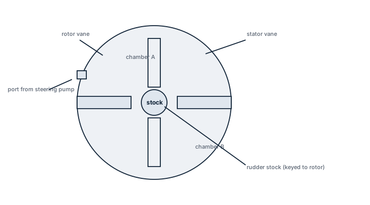
In a rotary vane steering gear the rotor is keyed straight onto the rudder stock, and vanes projecting from the rotor divide the surrounding stator housing into working chambers. Hydraulic oil fed to one side of each vane and drained from the other creates a pressure differential that acts directly on the stock as torque. There is no tiller arm, no quadrant, no connecting rod and no ram to translate linear force into rotation, which is exactly what separates this type from the two-ram or four-ram gear found on most…
What sets the rotary vane design apart
In a rotary vane steering gear the rotor is keyed straight onto the rudder stock, and vanes projecting from the rotor divide the surrounding stator housing into working chambers. Hydraulic oil fed to one side of each vane and drained from the other creates a pressure differential that acts directly on the stock as torque. There is no tiller arm, no quadrant, no connecting rod and no ram to translate linear force into rotation, which is exactly what separates this type from the two-ram or four-ram gear found on most large tankers and bulk carriers. The result is a compact, self-contained unit that sits on top of the rudder trunk rather than spread across the steering flat, at the cost of a more demanding sealing job at every vane tip and side face.
Main components
Rotor and vane assembly
The rotor carries three or four vanes machined or bolted into radial slots. Each vane seals against the stator bore and the rotor hub, and the sealing arrangement - usually a combination of PTFE-faced vane tip seals and side seals - is the part most exposed to wear because it moves under load every time the helm is worked.
Stator housing
The stator is a heavy cast or fabricated ring bolted to the rudder trunk structure, split into chambers by fixed stops that also act as the mechanical end stops limiting rudder travel. It has to absorb the full stall torque of the gear if the rudder is driven against a hard stop or an obstruction.
Hydraulic power unit
Twin pump sets, usually variable-displacement axial piston pumps on the larger sizes or fixed-displacement pumps with directional solenoid valves on smaller ones, supply the working chambers. SOLAS requires the main and auxiliary supplies to be independent so that a single pump, motor or pipe failure cannot disable steering.
Non-return, relief and buffer valves
Relief valves protect the housing from pressure spikes when the rudder meets green water or an unexpected load; buffer valves cushion the rotor as it approaches the mechanical stops so the vanes do not hammer against them at full helm.
Angle transmitter
A feedback unit mounted on the rotor or stock reports actual rudder angle back to the bridge indicator and to the autopilot. Misalignment here shows up as an indicated angle that does not match the rudder actually seen from aft.
Sizing and selection
The gear is selected on stall torque, not on rudder area alone: torque depends on rudder area, the ship's maximum ahead service speed squared, and the type of rudder, since a spade rudder with high lift needs more torque than a simple flat-plate rudder of the same area. Working pressure and vane count are then set to deliver that torque within the housing diameter the trunk allows.
- Rated torque at maximum working pressure, with margin for helm reversal under way
- Rudder angle range, normally 35 degrees each side with mechanical stops slightly beyond
- Response time from hard-over to hard-over at rated pump output
- Housing diameter versus the space available in the steering flat and rudder trunk
Regulations and class
SOLAS Chapter II-1 requires the main steering gear to put the rudder from 35 degrees on one side to 30 degrees on the other in not more than 28 seconds at maximum ahead service speed and deepest draught, and requires an independent auxiliary means capable of steering the ship on its own. Steering gear must be tested before departure, and class societies survey the gear periodically, including a tightness and function test and a check of the rudder stock coupling and seals.
Typical faults
| Fault | Consequence |
|---|---|
| Vane tip or side seal wear | Internal leakage between chambers, rudder creeps off course when the helm is left amidships |
| External seal or O-ring failure | Hydraulic oil loss, low reservoir alarm, eventual loss of pressure to one system |
| Non-return valve sticking | Pressure drop when changing over from main to auxiliary pump |
| Angle transmitter misalignment | Bridge indicator disagrees with actual rudder position, dangerous during pilotage |
| Stator housing overload from grounding contact | Cracking at the chamber stops, requiring dry-dock repair |
What to look for in a supplier
- A type test certificate from a recognised class society matching the rated torque to the actual rudder torque calculation, not just the nameplate figure
- Seal kits and vane tip seals held as stock spares, since these are wear items with a defined service life
- An angle transmitter output compatible with the existing autopilot and bridge indicator wiring
- A service network able to reach the vessel for the hydraulic power unit, not only the vane assembly
A slow, steady rudder creep with the helm amidships and no alarm is usually vane seal wear, not a control system fault - run the pre-departure test and watch the drift rate before blaming the autopilot.