Shaft Alignment System
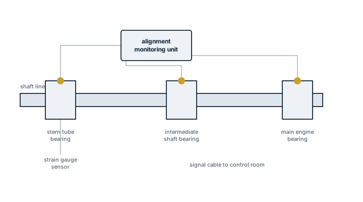
A shaft alignment system is the permanent instrumentation, usually strain-gauged bearings or an optical target line, that lets the crew confirm shaft alignment is still within tolerance in service, rather than relying only on the one-off yard survey done at build.
Read more — Shaft Alignment System explained ▾
What Sets an Onboard Alignment System Apart
Shaft alignment is normally set once, at newbuild or after a major repair, using jacking or laser methods with the shaft cold and the ship on the blocks or afloat but not straining under load. The problem is that hull deflection, thermal growth of the engine and gearbox, and wear in the stern tube bearing all shift the actual running alignment away from that baseline over months and years. A permanent shaft alignment system gives the crew a way to check running alignment without a shipyard visit, either through strain-gauged bearing housings that report load continuously, or through an optical or laser target line installed along the shaft that can be re-checked at intervals. It is a monitoring layer, not a substitute for the initial alignment procedure itself.
Main Components
Strain-Gauged Bearing Pads
Load cells or strain gauges bonded to selected line bearing housings measure the actual load each bearing is carrying; a bearing carrying markedly more or less than its design share signals the shaft line has moved out of tolerance.
Optical or Laser Target System
A fixed sighting line, either a traditional optical telescope and target setup or a laser and detector pair, installed along the shaft tunnel allows a re-check of the shaft's straightness against the original as-built reference without disturbing couplings.
Data Logging and Trend Display
On systems with continuous strain gauge output, a logger records bearing load over time so trends, not just a single snapshot, can be reviewed, which is what actually catches slow bearing wear before it becomes a vibration problem.
Reference Coupling Marks
Witness marks or dowel positions at each coupling, recorded at the original alignment, give a fixed baseline that any later jacking check or gap-and-sag measurement is compared against.
Selection and Sizing
The choice between a full continuous monitoring installation and a simpler set of reference marks for periodic manual checks depends mostly on shaft length and the number of line bearings; a long shaft line with several intermediate bearings benefits more from continuous load monitoring than a short, direct-coupled arrangement with one or two bearings. Accuracy requirement for optical or laser reference systems is typically in the range of a few hundredths of a millimetre over the shaft length, since alignment tolerances at the coupling are tight.
Regulations and Class
- Class rules require alignment to be verified and documented after any repair affecting the shaft line, main engine seating, or gearbox, and a jacking check or strain gauge reading is the accepted evidence.
- Survey intervals for shaft line inspection, including bearing clearance and alignment verification, follow the class society's continuous machinery survey or the shaft survey scheme the ship is enrolled in.
- No SOLAS chapter governs alignment directly; it falls under class rules and the engine and shafting manufacturer's approved procedure.
Typical Faults
| Fault | Consequence |
|---|---|
| Strain gauge cabling damaged or corroded in the tunnel environment | Loss of monitoring data exactly when a trend would have given early warning |
| Hull deflection from loading condition not accounted for | Alignment reading taken light ship does not represent the loaded, working condition |
| Stern tube bearing wear allowed to progress unmonitored | Shaft droop increases, load shifts onto adjacent line bearings, vibration rises |
| Reference marks lost or overpainted during maintenance | No fixed baseline left for a future jacking check comparison |
What to Look for in a Supplier
- A calibration certificate for strain gauge or laser equipment traceable to a recognised standard, since the whole point of the system is trustworthy numbers.
- Documented installation procedure that ties the monitoring system's baseline to the original class-witnessed alignment survey, not a separate unrelated reference.
- Data output format compatible with the ship's existing condition monitoring or planned maintenance software, to avoid a standalone system nobody reviews.
A jacking check done only with the ship in dry dock, light and cold, tells you little about how the shaft behaves loaded and warm at sea; where the system allows it, take a comparison reading under way as well.
1 manufacturers · 11 models
SKF Marine
11- High alignment accuracy (typically ±0.02 mm / ±0.1°)
- Fast set‑up and measurement compared with manual tools
- Integrated data storage for repeatable maintenance records
- Robust chock‑mount seal suitable for steel or polymer bearings
- Compatible with standard 100 mm shaft sizes common on many vessels
- Limited to shafts ≤100 mm; larger propulsion lines require a higher‑capacity system
- Requires clear line‑of‑sight and stable mounting, which can be difficult in cramped engine rooms
- Higher initial purchase cost than basic mechanical alignment kits
- Operator needs specific training to achieve full accuracy potential
- Not rated for extreme temperature or explosive atmospheres without additional housing
- High alignment accuracy suitable for large propulsion shafts
- Durable steel/polymer housing resists harsh marine environments
- Chock‑mount seal simplifies mounting on existing shaft lines
- Integrated measurement capability reduces need for separate tools
- Compatible with standard SKF bearing and monitoring accessories
- Limited to shafts up to 150 mm; larger diameters require a different model
- Initial setup and calibration demand trained personnel
- Higher upfront cost compared with basic mechanical dial‑indicator kits
- Requires periodic verification to maintain accuracy
- Physical size (225 mm length) may be restrictive in confined spaces
- Alignment accuracy typically within ±0.02 mm, reducing wear on bearings and couplings
- Integrated vibration sensor enables simultaneous condition monitoring
- Rugged housing rated for harsh marine environments (IP66/IEC‑60068)
- Seamless data interface with SKF Condition Monitoring System (CMS) platforms
- Quick set‑up and measurement workflow, reducing dry‑dock time
- Higher capital cost compared with basic mechanical alignment kits
- Requires trained personnel to operate the laser system and interpret data
- Limited to shaft diameters ≤200 mm; larger shafts need a different model
- Needs reliable power supply and data connection on board
- Physical size of the chock‑mount unit may be restrictive in very tight engine rooms
- High alignment accuracy for shafts up to 250 mm
- Robust steel/polymer bearings resist wear and corrosion
- Compact overall length (375 mm) eases installation in confined spaces
- SKF brand support and readily available spare parts
- Maximum shaft diameter limited to 250 mm
- Chock‑mount seal requires a precisely machined mounting surface
- No built‑in vibration monitoring – separate sensors are needed
- Weight and detailed dimensions not published, may be heavier than some lightweight competitors
- High alignment accuracy (typically ±0.02 mm / ±0.1°) for large‑diameter shafts
- Fast set‑up and measurement – reduces dry‑dock time
- Non‑contact laser measurement eliminates wear on the shaft
- Integrated data logging and reporting simplifies documentation
- Compatible with SKF’s alignment software and other diagnostic tools
- Higher purchase and training cost compared with manual dial‑indicator kits
- Requires a clean, well‑lit environment – dust or strong ambient light can affect laser performance
- Limited to shafts that are accessible for the handheld probe
- Needs a reliable power source and periodic calibration
- Operator must be trained in laser safety and alignment procedures
- Integrated accelerometer and temperature sensor in one compact chock‑mount package
- Direct compatibility with SKF Condition Monitoring System (CMS) for remote diagnostics
- Robust steel/polymer bearing design reduces wear and maintenance intervals
- Fast installation on existing shafts without major modifications
- High measurement accuracy suitable for main engine and reduction gear shafts
- Limited to shaft diameters of 350 mm or less – not usable on larger shafts
- Requires SKF‑specific software and training for full data exploitation
- Higher upfront cost compared with basic vibration transducers
- Proprietary data format may need conversion for third‑party monitoring platforms
- Installation must be performed by qualified personnel to ensure correct alignment
- Designed for shafts up to 400 mm, covering most medium‑size marine propulsion lines
- Robust steel/polymer bearing with chock‑mount seal simplifies installation and maintenance
- Integrated vibration sensor enables continuous condition monitoring alongside alignment checks
- Compatible with SKF diagnostic software for easy data export and trend analysis
- Proven reliability from SKF’s long‑standing marine product portfolio
- Limited to a maximum shaft diameter of 400 mm; larger shafts require a different solution
- Manual/mechanical measurement may be less precise than laser‑based systems for ultra‑tight tolerances
- Unit length (600 mm) and bearing size can add weight and space requirements in confined engine rooms
- Higher upfront cost compared with basic mechanical dial‑indicator kits
- Requires periodic calibration to maintain accuracy
- High alignment accuracy for shafts up to 500 mm diameter
- Robust steel/polymer bearing material tolerates harsh marine environments
- Integrated vibration monitoring helps detect misalignment early
- Chock‑mount design simplifies installation on existing shaft lines
- Limited to the specified shaft size range; not suitable for smaller or much larger shafts
- Requires skilled personnel for proper setup and calibration
- No published weight, power or dimension data makes integration planning less straightforward
- Higher upfront cost compared with basic mechanical alignment kits
- Designed specifically for shafts up to 600 mm, covering most main‑propulsion applications.
- Robust steel/polymer bearing material provides long service life in harsh marine environments.
- Chock‑mount seal protects the alignment assembly from water ingress and debris.
- Modular length of 900 mm fits a wide range of engine room layouts without major modifications.
- SKF’s reputation for accuracy gives alignment tolerances typically within ±0.02 mm.
- Limited to a maximum shaft diameter of 600 mm; larger shafts require a different model.
- Installation and calibration demand trained personnel, increasing initial labour cost.
- The system is relatively bulky, which may restrict placement in confined engine‑room spaces.
- Higher upfront purchase price compared with basic mechanical alignment tools.
- High alignment accuracy (≤0.02 mm) for shafts up to 700 mm diameter
- Integrated vibration sensors allow simultaneous condition monitoring
- Robust chock‑mount seal design tolerates harsh marine environments
- Modular setup – can be installed on existing shaft lines without major redesign
- SKF’s global support network provides calibration and training services
- Requires trained personnel for set‑up and interpretation of results
- Higher upfront cost compared with basic mechanical alignment kits
- Calibration intervals add to maintenance workload
- Limited to shafts within the specified diameter range – not suitable for smaller auxiliary shafts
- Physical size may complicate installation in confined engine rooms
- Real‑time, high‑resolution measurement of axial, angular and radial misalignment on shafts up to 800 mm diameter
- Integrated with SKF’s Condition Monitoring platform for remote data access and predictive maintenance
- Robust chock‑mount sealing suitable for harsh marine environments
- Self‑diagnosing sensors reduce false alarms and simplify commissioning
- Modular design allows expansion to multiple measurement points on a shaft line
- Higher upfront cost compared with manual alignment tools or lower‑capacity systems
- Installation requires skilled personnel and precise mounting to maintain sensor accuracy
- Limited to shafts within the specified diameter range; not suitable for smaller auxiliary shafts
- Requires periodic calibration and software updates to retain measurement fidelity
- Dependence on shipboard data network – performance can be affected by poor connectivity