What to check on a Power Management System.
A power management system (PMS) is the control layer sitting above the generator and switchboard protection relays, deciding automatically which generators start, stop, synchronise and share load, and which consumers get shed if demand exceeds available capacity. It is distinct from the switchboard protection itself: protection relays trip breakers to prevent damage after a fault, while the PMS tries to prevent the fault condition, an overload or blackout, from happening in the first place by managing load ahead of time. On ships with dynamic positioning or heavy dredging and crane…
What makes this type
A power management system (PMS) is the control layer sitting above the generator and switchboard protection relays, deciding automatically which generators start, stop, synchronise and share load, and which consumers get shed if demand exceeds available capacity. It is distinct from the switchboard protection itself: protection relays trip breakers to prevent damage after a fault, while the PMS tries to prevent the fault condition, an overload or blackout, from happening in the first place by managing load ahead of time. On ships with dynamic positioning or heavy dredging and crane loads, the PMS is what keeps generator loading within safe limits as demand swings rapidly, rather than relying on an engineer to bring a standby set on line manually in time.
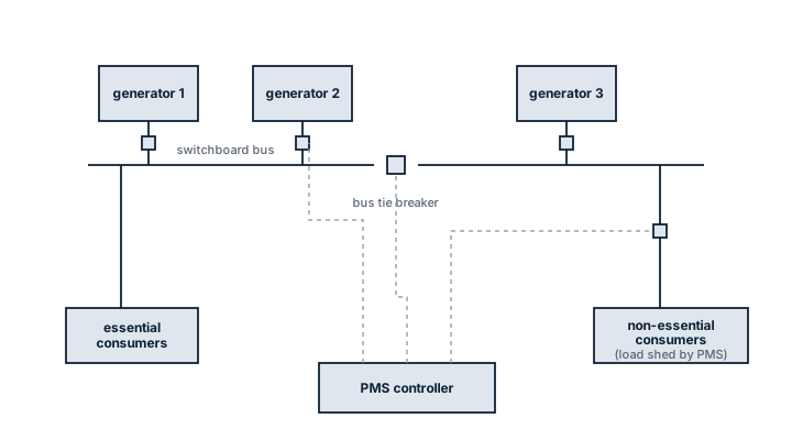
Main components
Load sharing controller
Compares real and reactive load between running generators and trims governor and AVR setpoints so each set carries its proportional share, typically holding kW sharing within a few percent.
Automatic synchroniser
Matches voltage, frequency and phase of an incoming generator to the busbar before closing the breaker, either check-synchronising or running full auto-sync sequences.
Load-dependent start/stop logic
Starts standby generators as load approaches a set threshold and stops surplus sets once load falls, based on configurable margins and timers to avoid hunting.
Load shedding module
Trips pre-ranked non-essential consumers, in priority tiers, the instant available generation falls below demand, to prevent a full blackout.
Blackout recovery / preferential trip sequence
Automatically restarts and resynchronises generators and restores essential loads in a fixed order after a blackout, rather than leaving that sequence to be done manually under pressure.
Selection / Sizing
- Number of generators and their individual and combined kW/kVA rating, which sets the sharing and shedding logic thresholds.
- DP class notation (if any): DP2/DP3 vessels need PMS logic that respects single-failure criteria, isolating faults to one bus section.
- Interface requirements with the integrated automation system and any thruster or drilling load management already on board.
- Redundancy of the PMS controller itself: a single PMS controller failure should not be able to blackout the ship.
- Configurability of load shedding priority tables to match the actual consumer list, not a generic default.
Regulations / Class
Classification societies require documented load shedding and blackout recovery arrangements as part of the electrical installation survey, and DP-notated vessels have additional requirements under the class DP notation (such as DNV DYNPOS or ABS DPS) covering independence between redundant power groups. SOLAS Ch. II-1 requires an emergency source of power independent of the main PMS logic. Failure mode and effects analysis (FMEA) is typically required for DP2/DP3 vessels to demonstrate that a single PMS fault cannot cause loss of position.
Typical faults
| Fault | Consequence |
|---|---|
| Load sharing drift between governors from ageing sensors | One generator carries disproportionate load, running hotter and closer to overload trip |
| Shedding priority table not updated after a refit added consumers | Essential load gets shed, or a non-essential load survives and worsens an overload |
| Synchroniser check-sync window set too tight | Standby generator repeatedly fails to close onto the bus, delaying load pickup |
| Software logic corruption or unbacked parameter changes after commissioning | Unpredictable start/stop or shed behaviour discovered only during an actual overload event |
| Loss of communication between PMS and generator controllers | System falls back to manual mode without alerting the watchkeeper in time |
What to look for in a supplier
- A track record of PMS integration with the specific generator and switchboard manufacturer already on board, not just a generic controller.
- FMEA documentation available for DP-classed vessels, ready to submit to class and the DP verification body.
- On-board configurability of shedding tables and start/stop thresholds without requiring a factory visit for every change.
- Redundant controller architecture for vessels where a single PMS fault is not an acceptable risk.
After any change to the ship's consumer list, walk the load shedding priority table again; a PMS that still sheds by an outdated list is worse than no automatic shedding at all, because the crew trusts it.