What to check on a Main Switchboard (LV).
The main switchboard is the single point where every generator on board feeds into a common busbar system before power is split out to distribution boards and final circuits. At low voltage, typically 380 to 690V on merchant vessels, it differs from a high-voltage switchboard, used on large cruise ships and some LNG carriers running at 6.6 or 11kV, mainly in insulation clearances and arc-flash energy involved, but the core job is the same: combine generator output safely, protect it, and share load between running generators without a fault in…
What Sets the Low-Voltage Main Switchboard Apart
The main switchboard is the single point where every generator on board feeds into a common busbar system before power is split out to distribution boards and final circuits. At low voltage, typically 380 to 690V on merchant vessels, it differs from a high-voltage switchboard, used on large cruise ships and some LNG carriers running at 6.6 or 11kV, mainly in insulation clearances and arc-flash energy involved, but the core job is the same: combine generator output safely, protect it, and share load between running generators without a fault in one section taking down the whole ship.
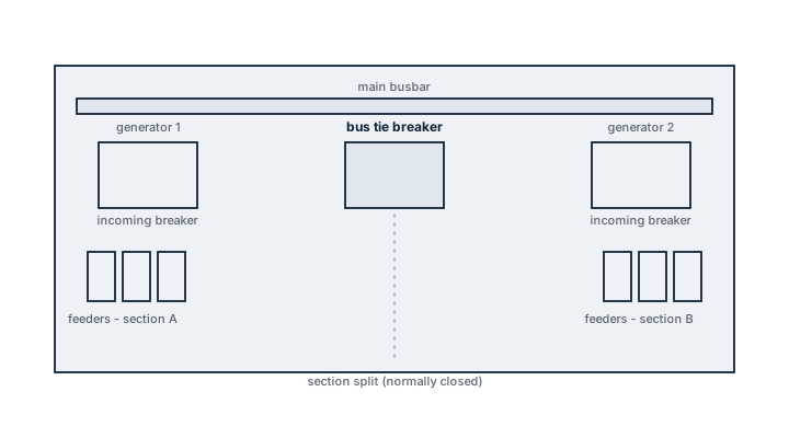
Main Components
Busbar system
Copper bars running the length of the switchboard, usually split into sections by bus-tie breakers so a fault or fire in one section can be isolated without blacking out the other.
Generator circuit breakers
Air circuit breakers rated to the generator's full load current, fitted with protection relays for overcurrent, short circuit, reverse power and, where applicable, differential protection.
Feeder breakers to distribution boards
Breakers sized to each downstream distribution board's load, coordinated with the generator breakers so a fault on a feeder trips only that feeder, not the generator supplying it.
Synchronising and load-sharing panel
Instruments and controls for bringing an additional generator onto the busbar in phase, matching voltage, frequency and phase sequence, and then sharing kW and kVAr load between running generators automatically or manually.
Protection relays and metering
Digital or electromechanical relays monitoring current, voltage, frequency and power factor on each section, feeding trip signals to the breakers and readings to the bridge and engine control room.
Selection and Sizing
Sizing follows total installed generator capacity, expected simultaneous load including starting currents of large motors, short-circuit fault current the busbar and breakers must withstand, and the degree of section splitting needed to meet the vessel's blackout-recovery and redundancy requirements. Passenger vessels and dynamic positioning vessels typically need finer sectionalising than a straightforward cargo ship.
Regulations and Class
Class rules, each society publishing its own electrical installation rules broadly aligned across IACS members, set minimum short-circuit withstand ratings, protection coordination requirements, and rules on section splitting for redundancy on vessels with class notations for dynamic positioning or enhanced survivability. SOLAS Ch. II-1 sets requirements for electrical installations generally, including emergency power arrangements that the main switchboard must be able to hand over to. Surveys check breaker settings against the approved protection coordination study and test insulation resistance at intervals set by class.
Typical Faults
- Protection relay settings drifted from the approved coordination study can let a downstream fault trip the generator breaker instead of the intended feeder breaker, causing a full blackout for what should have been a local trip.
- Loose busbar joints build up resistance and heat over time, occasionally to the point of an arc flash event.
- A synchronising equipment fault makes bringing a second generator online manually risky and slow exactly when the crew needs it fastest, during blackout recovery.
- Insulation degradation from moisture or salt ingress in engine room atmosphere shows up first as intermittent earth fault alarms before a hard failure.
What to Look for in a Supplier
- A protection coordination study delivered with the switchboard, not left for the yard or owner to commission separately.
- Short-circuit withstand rating with margin above the calculated fault current, not the bare minimum.
- Access and layout that lets breakers be withdrawn and tested without shutting down the whole board.
Keep the protection coordination study on board and check breaker settings against it after any relay replacement: a relay swapped in with default settings instead of the ship's coordinated settings is a common cause of a nuisance-trip blackout.