Shell-and-Tube Cooler
A shell-and-tube cooler passes cooling water through a tube bundle inside a shell while oil or jacket water flows around it, trading the compactness of a plate cooler for tubes that can be mechanically cleaned and individually plugged without stopping the plant.
Read more — Shell-and-Tube Cooler explained ▾
What sets a shell-and-tube cooler apart
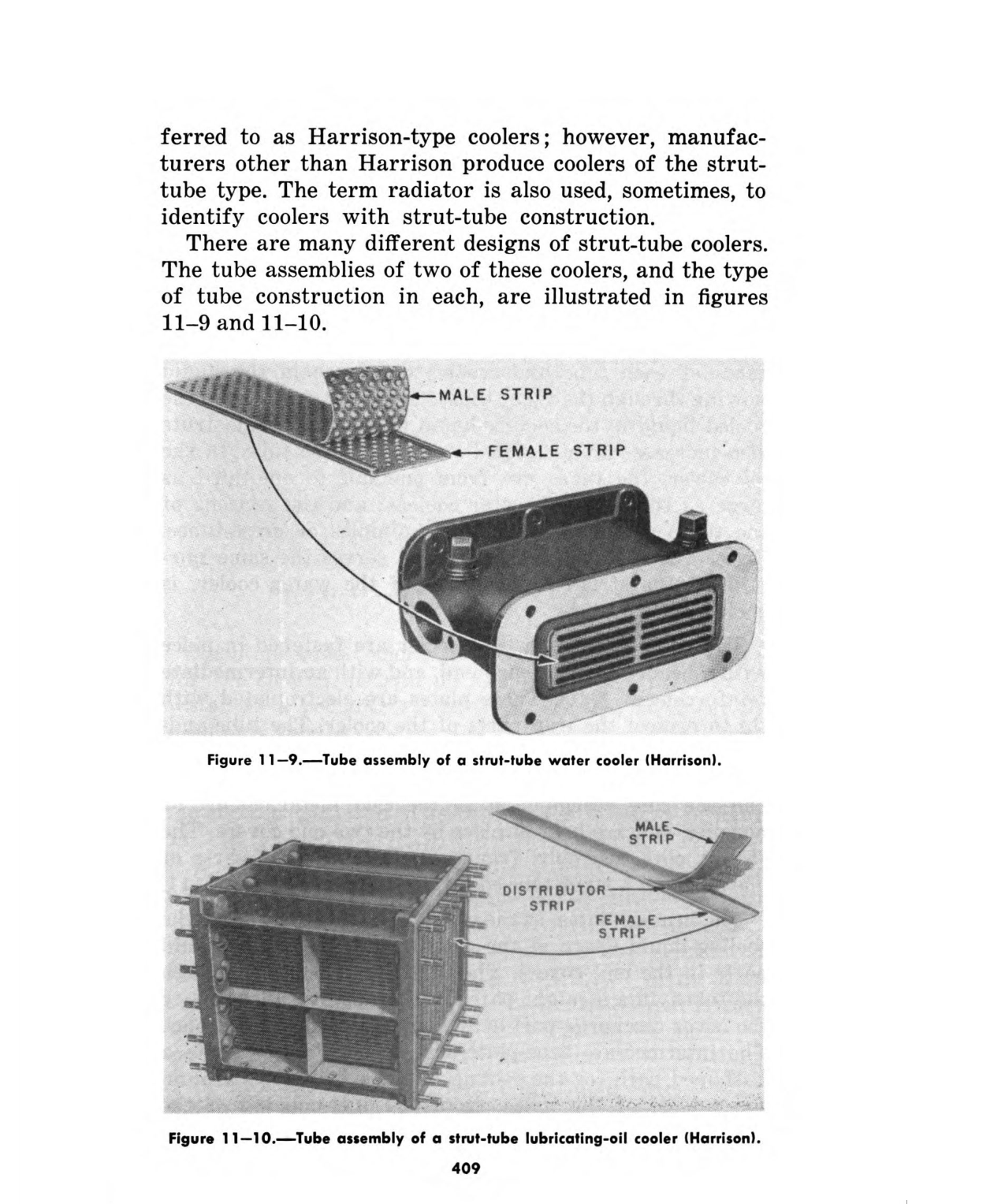
Inside the shell, a bundle of straight or U-tubes carries one fluid, usually sea water or low-temperature fresh water, while the second fluid, jacket water, lubricating oil or charge air, flows through the shell around the outside of the tubes, redirected back and forth by baffles to improve contact time. Compared with a plate heat exchanger, a shell-and-tube design gives up compactness and thermal efficiency per square metre, but it tolerates dirtier, more corrosive water, handles higher pressure differentials without gasket concerns, and lets a single leaking tube be plugged and left out of service rather than forcing a full plate-pack strip-down.

Main components
Shell
The outer pressure-containing cylinder, usually carbon steel with a corrosion allowance or a cladding on the water side.
Tube bundle
Copper-nickel tubes, 90/10 or 70/30 CuNi, are standard where raw sea water is the coolant, chosen for resistance to biofouling and erosion-corrosion; titanium tubes appear on high-duty or aggressive-water applications. Tube walls run roughly 0.7-1.2 mm.
Tube sheets
Thick plates at each end that the tubes are expanded or welded into, separating the shell side from the water boxes.
Baffles
Segmental plates spaced along the bundle that force the shell-side fluid into a zig-zag path, raising turbulence and heat transfer at the cost of pressure drop.
Water boxes and end covers
Removable covers at each end that let the tube bundle be pulled for cleaning or replacement without disturbing the shell-side piping.
Selection and sizing
Sizing runs on heat duty in kW, the temperature approach between the two fluids, allowable pressure drop on each side, and a fouling factor assumed for the water quality expected in service. Sea water coolers are usually oversized against a clean-tube calculation specifically to absorb the fouling that will accumulate between cleanings. Tube material, number of passes and bundle length are the practical trade-offs weighed against available engine room space and the vessel's typical trading water quality.
Regulations and class
Shell-and-tube coolers in essential cooling services fall under class society rules for machinery piping systems, which set minimum design pressure, material approval and testing requirements, typically a hydrostatic test at 1.5 times design pressure. Where the cooler sits in a fuel oil or lubricating oil circuit near hot surfaces, SOLAS II-2 insulation and leakage-containment requirements apply to the surrounding installation rather than to the cooler itself. There is no fixed statutory survey interval specific to the cooler; it is covered under the periodic survey of the cooling water and lubricating oil systems in the vessel's class survey scheme.
Typical faults
| Fault | Cause | Consequence |
|---|---|---|
| Tube fouling | Marine growth, silt or scale on the water side | Falling heat transfer, rising jacket water or LO temperature over weeks |
| Tube erosion | Sea water velocity too high, or sand and grit ingestion | Wall thinning, eventual pinhole leak and cross-contamination |
| Galvanic corrosion | Mismatched tube and tube sheet materials, or exhausted sacrificial anodes | Localised pitting, tube failure well before nominal service life |
| Tube-to-tube-sheet leak | Expansion fatigue or poor original rolling | Sea water into the oil or fresh water side, contaminating the lubricant |
| Water box gasket failure | Age and thermal cycling | External leak, loss of cooling water inventory |
What to look for in a supplier
- Class-approved design with certified hydrostatic test records for both shell and tube sides.
- Tube material recommendation matched to the vessel's actual trading area water quality, not a generic default.
- Availability of replacement tube bundles or individual tubes sized to the existing tube sheet pattern, so a repair does not require a whole new cooler.
- Anode fitment and access for renewal without pulling the full bundle.
Pull and inspect the tube bundle at the interval the water quality earns, not the interval on the maintenance sheet - a cooler running clean, filtered fresh water fouls far slower than one on raw estuary sea water.
Technical drawings & plates
Historical engineering archive — public domain sources, cited per plate. Principles shown remain valid; always consult the OEM manual for model-specific data.
10 manufacturers · 17 models
Alfa Laval
5- Design Pressure M-Line
- >10 bar (145 psi)
- Marine Engine Room Modelle
- T6 (DN60, 800 kW) bis T35 (DN350, 35.000 kW)
- Marine FSRU Modelle
- TS45, T45, T50 (DN450-500, 45.000-55.000 kW)
- Temperaturbereich Standard
- 0–180°C (depending on model)
- FSRU Temperaturbereich
- -50 bis 150°C
- Plattentypen
- Chevron, Gemini Doppelwand, FlexFlow™
- M-Line (High Pressure Series: M3, M6, M10, M15)
- T-Series (Industrial: T2, T5, T6, T8, T10, T20, T25)
- AQ-Series (HVAC: AQ1, AQ2, AQ3, AQ4, AQ10)
- Marine Line (Engine Room: T6-T35; FSRU: TS45, T45, T50)
- Baseline (Competitive Line)
- Hygienic Line (Premium)
- Area: Gasket wear and embrittlementCheck: Inspect seals visually for cracks, hardening, swelling and discoloration; verify material compatibility with process fluids; check ClipGrip™ fastening. Aging symptoms and loss of elasticity are replacement indicators.
- Area: Clamping dimension and tightness (Tightening Dimension A)Check: Verify A-dimension per manufacturer specifications with caliper (metallic contact required). Keep bolts clean and lubricated. Avoid over-tightening. Perform regular re-tightening after operating hours. At too low A-dimension, pressure loss and leakage are to be expected.
- Area: Fouling and scale formation on plate surfacesCheck: Monitor pressure differential across heat exchanger (increase indicates deposits). Check heat duty versus design value. Optimize CIP intervals after performance audits. Deposits generate higher pump load (energy waste up to 8,000 kWh/year possible).
- Area: Plate corrosion and cracks / breakthroughsCheck: After disassembly, inspect plate surfaces for local measurements (pitting), cracks and perforation corrosion. Verify material compatibility with process fluid. Observe fatigue cracks especially at corners and transitions. When perforation occurs, plate is unrecoverable and must be replaced.
- Area: Pressure test and tightness inspectionCheck: After disassembly and cleaning, perform hydrostatic test per data sheet. Test pressure typically 1.5× operating pressure. Check external and internal leakage at all connections and plate edges. Document findings.
- Area: Plate sequence and alignment (5-point alignment)Check: After opening, verify plate sequence and honeycomb pattern (corrected chevron patterns must alternate). Activate/validate 5-point alignment system for larger units. Offset or misplacement leads to short-circuiting and reduced heat duty.
Type-universal inspection points for Alfa Laval Gasketed Plate Heat Exchangers (GPHE) (Alfa Laval, 2026-06). Per-model specs not auto-populated.
- High design pressure (>10 bar) suitable for large marine engines up to 35 MW
- Wide temperature capability (0‑180 °C standard, –50‑150 °C for FSRU models)
- Modular DN series (DN60‑DN500) covers a broad range of vessel sizes
- Alfa Laval’s proven reliability and extensive service network
- Straightforward maintenance: annual seawater side cleaning and 5‑year tube eddy‑current testing
- Relatively heavy and large footprint compared with compact plate exchangers
- Requires regular gasket inspection and possible replacement in high‑temperature loops
- Fouling risk in high‑salinity seawater; performance degrades if cleaning intervals are missed
- Maximum temperature limited to 180 °C, unsuitable for very high‑temp processes
- Periodic tube integrity testing adds to maintenance planning
- Design Pressure M-Line
- >10 bar (145 psi)
- Marine Engine Room Modelle
- T6 (DN60, 800 kW) bis T35 (DN350, 35.000 kW)
- Marine FSRU Modelle
- TS45, T45, T50 (DN450-500, 45.000-55.000 kW)
- Temperaturbereich Standard
- 0–180°C (depending on model)
- FSRU Temperaturbereich
- -50 bis 150°C
- Plattentypen
- Chevron, Gemini Doppelwand, FlexFlow™
- M-Line (High Pressure Series: M3, M6, M10, M15)
- T-Series (Industrial: T2, T5, T6, T8, T10, T20, T25)
- AQ-Series (HVAC: AQ1, AQ2, AQ3, AQ4, AQ10)
- Marine Line (Engine Room: T6-T35; FSRU: TS45, T45, T50)
- Baseline (Competitive Line)
- Hygienic Line (Premium)
- Area: Gasket wear and embrittlementCheck: Inspect seals visually for cracks, hardening, swelling and discoloration; verify material compatibility with process fluids; check ClipGrip™ fastening. Aging symptoms and loss of elasticity are replacement indicators.
- Area: Clamping dimension and tightness (Tightening Dimension A)Check: Verify A-dimension per manufacturer specifications with caliper (metallic contact required). Keep bolts clean and lubricated. Avoid over-tightening. Perform regular re-tightening after operating hours. At too low A-dimension, pressure loss and leakage are to be expected.
- Area: Fouling and scale formation on plate surfacesCheck: Monitor pressure differential across heat exchanger (increase indicates deposits). Check heat duty versus design value. Optimize CIP intervals after performance audits. Deposits generate higher pump load (energy waste up to 8,000 kWh/year possible).
- Area: Plate corrosion and cracks / breakthroughsCheck: After disassembly, inspect plate surfaces for local measurements (pitting), cracks and perforation corrosion. Verify material compatibility with process fluid. Observe fatigue cracks especially at corners and transitions. When perforation occurs, plate is unrecoverable and must be replaced.
- Area: Pressure test and tightness inspectionCheck: After disassembly and cleaning, perform hydrostatic test per data sheet. Test pressure typically 1.5× operating pressure. Check external and internal leakage at all connections and plate edges. Document findings.
- Area: Plate sequence and alignment (5-point alignment)Check: After opening, verify plate sequence and honeycomb pattern (corrected chevron patterns must alternate). Activate/validate 5-point alignment system for larger units. Offset or misplacement leads to short-circuiting and reduced heat duty.
Type-universal inspection points for Alfa Laval Gasketed Plate Heat Exchangers (GPHE) (Alfa Laval, 2026-06). Per-model specs not auto-populated.
- Design Pressure M-Line
- >10 bar (145 psi)
- Marine Engine Room Modelle
- T6 (DN60, 800 kW) bis T35 (DN350, 35.000 kW)
- Marine FSRU Modelle
- TS45, T45, T50 (DN450-500, 45.000-55.000 kW)
- Temperaturbereich Standard
- 0–180°C (depending on model)
- FSRU Temperaturbereich
- -50 bis 150°C
- Plattentypen
- Chevron, Gemini Doppelwand, FlexFlow™
- M-Line (High Pressure Series: M3, M6, M10, M15)
- T-Series (Industrial: T2, T5, T6, T8, T10, T20, T25)
- AQ-Series (HVAC: AQ1, AQ2, AQ3, AQ4, AQ10)
- Marine Line (Engine Room: T6-T35; FSRU: TS45, T45, T50)
- Baseline (Competitive Line)
- Hygienic Line (Premium)
- Area: Gasket wear and embrittlementCheck: Inspect seals visually for cracks, hardening, swelling and discoloration; verify material compatibility with process fluids; check ClipGrip™ fastening. Aging symptoms and loss of elasticity are replacement indicators.
- Area: Clamping dimension and tightness (Tightening Dimension A)Check: Verify A-dimension per manufacturer specifications with caliper (metallic contact required). Keep bolts clean and lubricated. Avoid over-tightening. Perform regular re-tightening after operating hours. At too low A-dimension, pressure loss and leakage are to be expected.
- Area: Fouling and scale formation on plate surfacesCheck: Monitor pressure differential across heat exchanger (increase indicates deposits). Check heat duty versus design value. Optimize CIP intervals after performance audits. Deposits generate higher pump load (energy waste up to 8,000 kWh/year possible).
- Area: Plate corrosion and cracks / breakthroughsCheck: After disassembly, inspect plate surfaces for local measurements (pitting), cracks and perforation corrosion. Verify material compatibility with process fluid. Observe fatigue cracks especially at corners and transitions. When perforation occurs, plate is unrecoverable and must be replaced.
- Area: Pressure test and tightness inspectionCheck: After disassembly and cleaning, perform hydrostatic test per data sheet. Test pressure typically 1.5× operating pressure. Check external and internal leakage at all connections and plate edges. Document findings.
- Area: Plate sequence and alignment (5-point alignment)Check: After opening, verify plate sequence and honeycomb pattern (corrected chevron patterns must alternate). Activate/validate 5-point alignment system for larger units. Offset or misplacement leads to short-circuiting and reduced heat duty.
Type-universal inspection points for Alfa Laval Gasketed Plate Heat Exchangers (GPHE) (Alfa Laval, 2026-06). Per-model specs not auto-populated.
- Design Pressure M-Line
- >10 bar (145 psi)
- Marine Engine Room Modelle
- T6 (DN60, 800 kW) bis T35 (DN350, 35.000 kW)
- Marine FSRU Modelle
- TS45, T45, T50 (DN450-500, 45.000-55.000 kW)
- Temperaturbereich Standard
- 0–180°C (depending on model)
- FSRU Temperaturbereich
- -50 bis 150°C
- Plattentypen
- Chevron, Gemini Doppelwand, FlexFlow™
- M-Line (High Pressure Series: M3, M6, M10, M15)
- T-Series (Industrial: T2, T5, T6, T8, T10, T20, T25)
- AQ-Series (HVAC: AQ1, AQ2, AQ3, AQ4, AQ10)
- Marine Line (Engine Room: T6-T35; FSRU: TS45, T45, T50)
- Baseline (Competitive Line)
- Hygienic Line (Premium)
- Area: Gasket wear and embrittlementCheck: Inspect seals visually for cracks, hardening, swelling and discoloration; verify material compatibility with process fluids; check ClipGrip™ fastening. Aging symptoms and loss of elasticity are replacement indicators.
- Area: Clamping dimension and tightness (Tightening Dimension A)Check: Verify A-dimension per manufacturer specifications with caliper (metallic contact required). Keep bolts clean and lubricated. Avoid over-tightening. Perform regular re-tightening after operating hours. At too low A-dimension, pressure loss and leakage are to be expected.
- Area: Fouling and scale formation on plate surfacesCheck: Monitor pressure differential across heat exchanger (increase indicates deposits). Check heat duty versus design value. Optimize CIP intervals after performance audits. Deposits generate higher pump load (energy waste up to 8,000 kWh/year possible).
- Area: Plate corrosion and cracks / breakthroughsCheck: After disassembly, inspect plate surfaces for local measurements (pitting), cracks and perforation corrosion. Verify material compatibility with process fluid. Observe fatigue cracks especially at corners and transitions. When perforation occurs, plate is unrecoverable and must be replaced.
- Area: Pressure test and tightness inspectionCheck: After disassembly and cleaning, perform hydrostatic test per data sheet. Test pressure typically 1.5× operating pressure. Check external and internal leakage at all connections and plate edges. Document findings.
- Area: Plate sequence and alignment (5-point alignment)Check: After opening, verify plate sequence and honeycomb pattern (corrected chevron patterns must alternate). Activate/validate 5-point alignment system for larger units. Offset or misplacement leads to short-circuiting and reduced heat duty.
Type-universal inspection points for Alfa Laval Gasketed Plate Heat Exchangers (GPHE) (Alfa Laval, 2026-06). Per-model specs not auto-populated.
- Design Pressure M-Line
- >10 bar (145 psi)
- Marine Engine Room Modelle
- T6 (DN60, 800 kW) bis T35 (DN350, 35.000 kW)
- Marine FSRU Modelle
- TS45, T45, T50 (DN450-500, 45.000-55.000 kW)
- Temperaturbereich Standard
- 0–180°C (depending on model)
- FSRU Temperaturbereich
- -50 bis 150°C
- Plattentypen
- Chevron, Gemini Doppelwand, FlexFlow™
- M-Line (High Pressure Series: M3, M6, M10, M15)
- T-Series (Industrial: T2, T5, T6, T8, T10, T20, T25)
- AQ-Series (HVAC: AQ1, AQ2, AQ3, AQ4, AQ10)
- Marine Line (Engine Room: T6-T35; FSRU: TS45, T45, T50)
- Baseline (Competitive Line)
- Hygienic Line (Premium)
- Area: Gasket wear and embrittlementCheck: Inspect seals visually for cracks, hardening, swelling and discoloration; verify material compatibility with process fluids; check ClipGrip™ fastening. Aging symptoms and loss of elasticity are replacement indicators.
- Area: Clamping dimension and tightness (Tightening Dimension A)Check: Verify A-dimension per manufacturer specifications with caliper (metallic contact required). Keep bolts clean and lubricated. Avoid over-tightening. Perform regular re-tightening after operating hours. At too low A-dimension, pressure loss and leakage are to be expected.
- Area: Fouling and scale formation on plate surfacesCheck: Monitor pressure differential across heat exchanger (increase indicates deposits). Check heat duty versus design value. Optimize CIP intervals after performance audits. Deposits generate higher pump load (energy waste up to 8,000 kWh/year possible).
- Area: Plate corrosion and cracks / breakthroughsCheck: After disassembly, inspect plate surfaces for local measurements (pitting), cracks and perforation corrosion. Verify material compatibility with process fluid. Observe fatigue cracks especially at corners and transitions. When perforation occurs, plate is unrecoverable and must be replaced.
- Area: Pressure test and tightness inspectionCheck: After disassembly and cleaning, perform hydrostatic test per data sheet. Test pressure typically 1.5× operating pressure. Check external and internal leakage at all connections and plate edges. Document findings.
- Area: Plate sequence and alignment (5-point alignment)Check: After opening, verify plate sequence and honeycomb pattern (corrected chevron patterns must alternate). Activate/validate 5-point alignment system for larger units. Offset or misplacement leads to short-circuiting and reduced heat duty.
Type-universal inspection points for Alfa Laval Gasketed Plate Heat Exchangers (GPHE) (Alfa Laval, 2026-06). Per-model specs not auto-populated.
Kelvion
3- Fouling on the heat-transfer surfaces from scale, sludge, biological growth, or oil contamination reduces thermal performance and appears as rising outlet temperature or reduced temperature approach
- Gasket, seal, tube, or plate leakage caused by ageing, corrosion, or mechanical damage can allow external leakage or cross-contamination between circuits
- Restricted flow from debris or deposits raises differential pressure and can reduce downstream flow
- Corrosion or erosion of wetted surfaces caused by unsuitable water chemistry, velocity, or material attack can produce pinhole leakage and contamination
- Loose covers, plate packs, or connections after maintenance can cause leakage, unstable temperatures, or loss of system pressure
- Fouling on heat-transfer surfaces from scale, sludge, biological growth, or oil contamination reduces thermal performance and appears as rising outlet temperature
- Gasket, seal, tube, or plate leakage from ageing, corrosion, or mechanical damage causes external leakage or cross-contamination
- Restricted flow from debris or deposits raises pressure drop and reduces downstream flow
- Corrosion or erosion of wetted surfaces from unsuitable water chemistry, velocity, or material attack produces pinhole leakage
- Loose covers, plate packs, or connections after maintenance cause leakage, unstable temperatures, or loss of system pressure
- Fouling or deposit build-up caused by poor combustion, contaminated fluid or exhaust soot can reduce heat transfer or flow and produce higher temperatures or loss of capacity
- Leakage from tubes, gaskets, seals or casing caused by corrosion, thermal cycling or erosion can appear as fluid loss, pressure decay or cross-contamination
- Burner, ignition or fuel-control faults where combustion is used can cause flame failure, unstable firing, smoke or shutdown alarms
- Fan, pump or actuator faults caused by mechanical wear or electrical problems can reduce circulation, airflow or treatment effectiveness
- Sensor, control or safety-interlock faults caused by drift, wiring defects or contamination can trigger nuisance trips or allow unstable operation
World Energy
2BITZER Kühlmaschinenbau
1Bowman
1- Fouling or scaling increases differential pressure and reduces heat-transfer performance
- Gasket, seal or tube-joint deterioration causes external leakage
- Plate or tube corrosion, erosion or cracking causes internal cross-contamination between fluid circuits
- Blocked strainers or restricted valves reduce flow and produce abnormal inlet-to-outlet temperatures
- Incorrect reassembly, venting or flow distribution after service causes leakage or poor thermal performance
- Compact shell‑and‑tube layout fits confined engine rooms
- Integrated sacrificial zinc anodes simplify corrosion control
- Tube bundle can be hydroblasted during drydock for effective fouling removal
- Standard marine connections compatible with most main and auxiliary engine systems
- Tube material prone to seawater‑induced corrosion/erosion if not properly maintained
- Heat‑transfer efficiency drops quickly with tube bundle fouling; requires regular temperature monitoring
- End‑cover gaskets may develop leaks under vibration or thermal cycling
- Zinc anodes deplete rapidly in high salinity, necessitating annual replacement