Service Air Compressor
Service air compressors supply low-pressure air, typically 5-10 bar, for control systems, pneumatic tools and deck machinery, a separate duty from the 25-30 bar starting air compressors that charge the main engine air receivers.
Read more — Service Air Compressor explained ▾
What Sets a Service Air Compressor Apart
A service air compressor supplies the ship's low-pressure air systems: control air for pneumatic valve actuators and instrumentation, general service air for pneumatic tools and deck equipment, and sometimes air for whistle or general utility use. This is a distinct duty from the starting air compressors that charge the high-pressure receivers used to start the main and auxiliary engines, which typically work at 25 to 30 bar rather than the 5 to 10 bar range of a service air unit. Because service air feeds control systems that must not fail, most vessels run duplicate compressors on this duty with automatic changeover, and because moisture in the control air line causes actuator and instrument faults rather than a starting failure, service air systems place more emphasis on drying than starting air systems typically do.
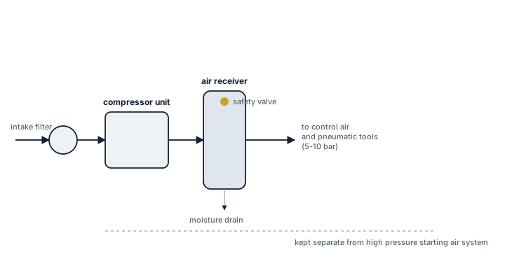
Main Components
Compression stage
Reciprocating piston units remain common at this pressure and capacity range, though screw compressors are increasingly fitted for their lower vibration and simpler oil-free options; single-stage designs are common given the modest pressure ratio required.
Air receiver
A pressure vessel that stores compressed air and smooths out demand peaks so the compressor does not need to run continuously; sized to give a reasonable run/rest cycle for the compressor motor.
Air dryer
Refrigerant or desiccant dryers remove moisture before the air reaches control valves and instruments, since condensate in a control air line freezes or corrodes small-bore piping and actuator components that starting air systems do not have to deal with.
Automatic control and changeover panel
A pressure switch or PLC-based control starts and stops the duty compressor on demand and brings the standby unit on line automatically if pressure falls below a set point, since control air loss can cascade into multiple system failures at once.
Selection and Sizing
Sizing follows total connected air demand rather than a single large-consumer figure, since control air demand is continuous while tool and deck air demand is intermittent:
- Free air delivery (m³/h or l/min) at the rated working pressure, sized with margin for simultaneous control and tool air demand
- Working pressure and pressure band the downstream control system actually requires, typically around 7 bar for many pneumatic actuators
- Receiver volume matched to compressor capacity to avoid excessive start/stop cycling
- Dryer dew point specification appropriate to the ambient conditions the vessel trades in
- Oil-free versus lubricated compression, since some control systems specify oil-free air to protect sensitive instrumentation
Regulations and Class
Class rules require a minimum number of independent air compressors for engine room service air and require the pressure vessels in the system, including the receiver, to undergo periodic internal and hydraulic pressure testing on the vessel's standard survey cycle for pressure vessels. Safety valves on the receiver must be set and tested to class requirements, and where the service air system supplies safety-related control functions, class typically expects the redundancy of a duplicate compressor with automatic changeover to be demonstrated at survey rather than only described on paper.
Typical Faults
| Fault | Cause | Consequence |
|---|---|---|
| Moisture carry-over into control air | Dryer undersized or faulty, condensate drain blocked | Actuator sticking, instrument air line freezing in cold climates, control valve malfunction |
| Excessive short-cycling | Undersized receiver relative to compressor capacity | Accelerated motor and valve wear, premature compressor failure |
| Automatic changeover failure | Faulty pressure switch, standby compressor not exercised regularly | Loss of control air with no automatic backup when the duty unit trips |
| Receiver corrosion | Inadequate condensate draining over time, missed internal inspection | Reduced wall thickness, failed pressure test, potential rupture risk |
What to Look for in a Supplier
- Documented free air delivery at the vessel's actual working pressure, not a compressor's peak rated output
- Dryer performance suited to the trading area's ambient humidity and temperature range
- Availability of oil-free options where the control system specification calls for them
- Spares support for the specific compressor model, since piston rings, valves and dryer cartridges are consumable items with regular replacement intervals
Test the automatic changeover to standby manually on a set schedule, not only when the duty compressor actually trips — a changeover relay that has never been exercised is the least trustworthy part of the system precisely because it is the part that is least often called on.
14 manufacturers · 315 models
Kaeser Marine
45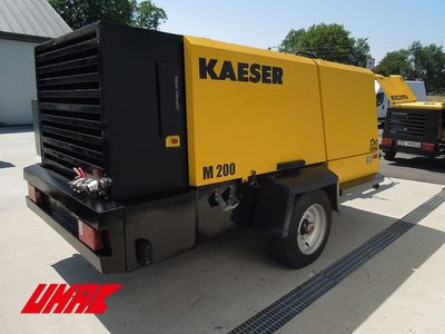
Ingersoll Rand Marine
41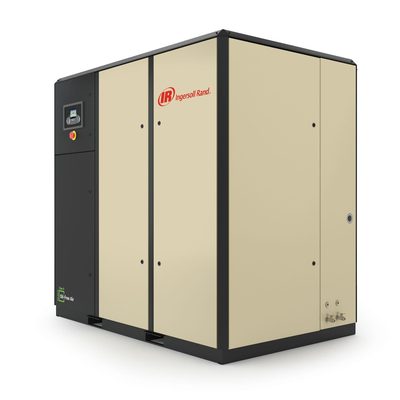
Haug (Sauer)
37
Mattei Marine
35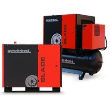
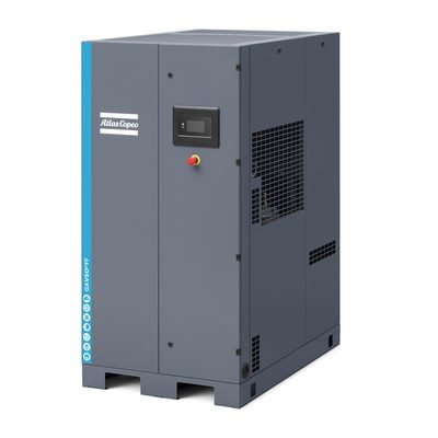
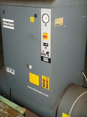
Atlas Copco Marine
31

Tamrotor
23
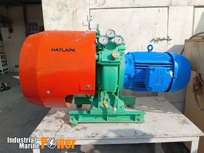
Hatlapa
21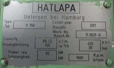
J.P. Sauer & Sohn
20
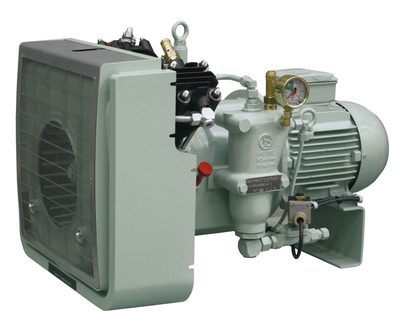
Sperre
20

Tanabe
15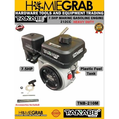
- Oil separator element clogging
- Minimum pressure valve stuck
- Screw element wear
- Thermostatic valve failure
- Continuous‑duty design suitable for round‑the‑clock operation
- Compact footprint compared with piston units of similar power
- Low noise and vibration levels typical of screw compressors
- Straightforward maintenance schedule (oil/separator change every 4 000 h, annual cooler cleaning)
- Adequate pressure (7 bar) for most shipboard pneumatic tools
- Oil‑contaminated air possible if oil separator becomes clogged
- Single stage limits maximum pressure; not suitable for high‑pressure applications (>10 bar)
- Requires regular oil handling and disposal
- Minimum‑pressure valve may stick, leading to shutdowns
- Screw element wear can reduce efficiency over long service intervals
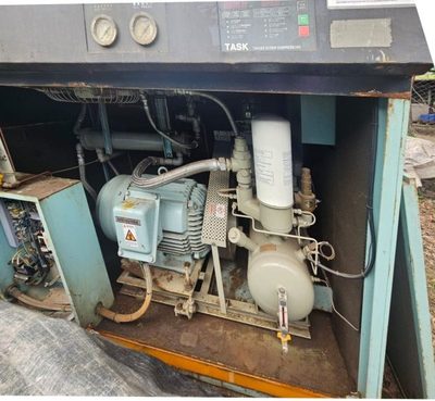
ABK
14
Sauer
11
Sauer Compressors
1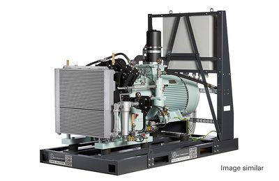
- Valve failure
- Oil separator saturation
- Motor overheating in tropical conditions
- Compact 22 kW footprint suitable for medium‑size vessels
- Two‑stage compression provides stable 10 bar output for most shipboard tools
- Dual capability – can supply service air to machinery spaces and deck equipment
- Oil separator life of ~2000 h reduces routine maintenance frequency
- Proven track record with Sauer’s marine‑grade construction
- Motor prone to overheating in tropical ambient temperatures unless additional cooling is provided
- Valve failures reported if regular inspection/adjustment is neglected
- Oil separator can become saturated quickly under heavy continuous use, requiring more frequent changes
- Maximum pressure limited to 10 bar – not suitable for high‑pressure pneumatic systems
- Requires scheduled oil change and filter maintenance typical of oil‑lubricated units
Wärtsilä
1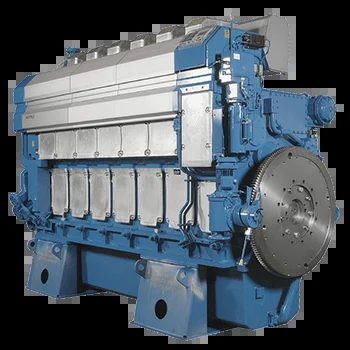
- Valve plate wear
- Aftercooler corrosion
- Pressure switch failure
- Simple, proven mechanical design with low initial cost
- Robust construction suitable for harsh marine environments
- Easy access for routine valve plate service (4000–6000 h intervals)
- Compact footprint compared with larger multi‑stage units
- Single‑stage limits maximum pressure to ~7 bar, unsuitable for high‑pressure applications
- Valve plate wear and aftercooler corrosion are recurring maintenance items
- Pressure switch reliability can be an issue in vibration‑heavy installations
- Limited power output (15 kW) may not meet larger vessel air demand