Bridge Integration System (IBS/INS)
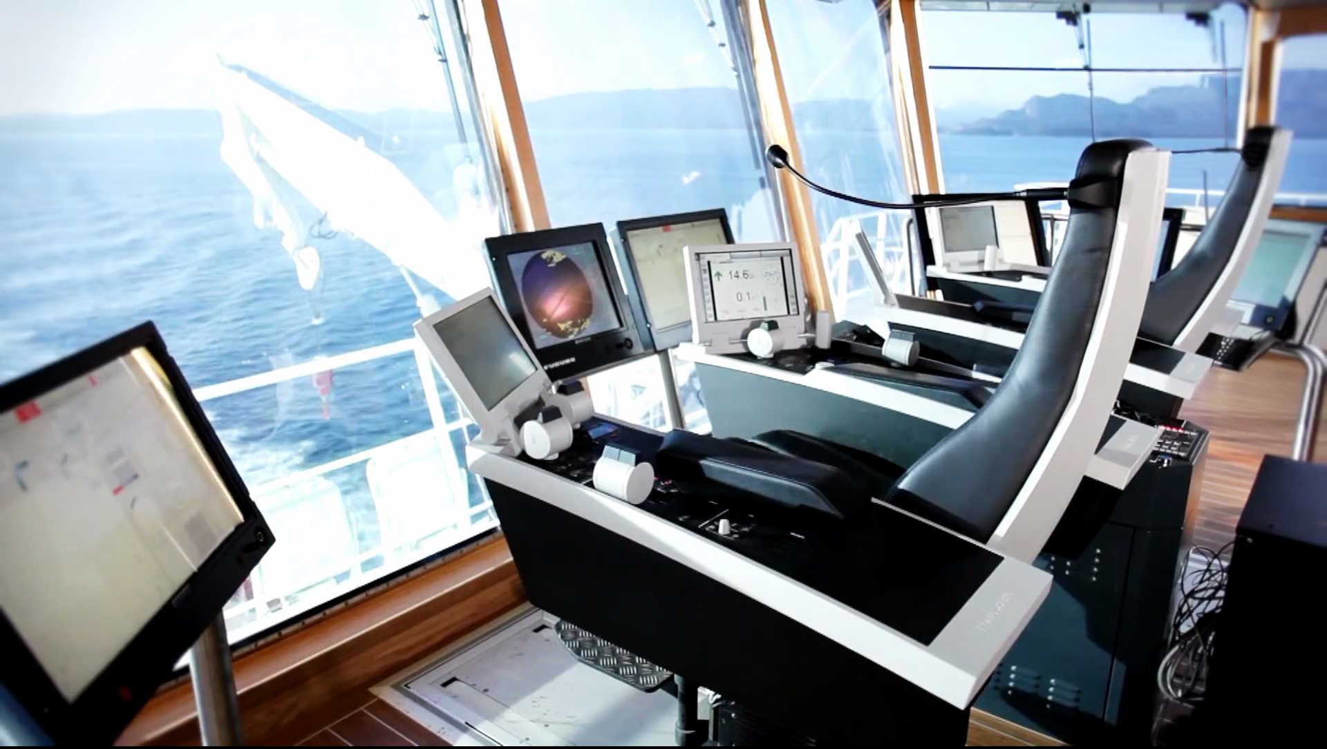
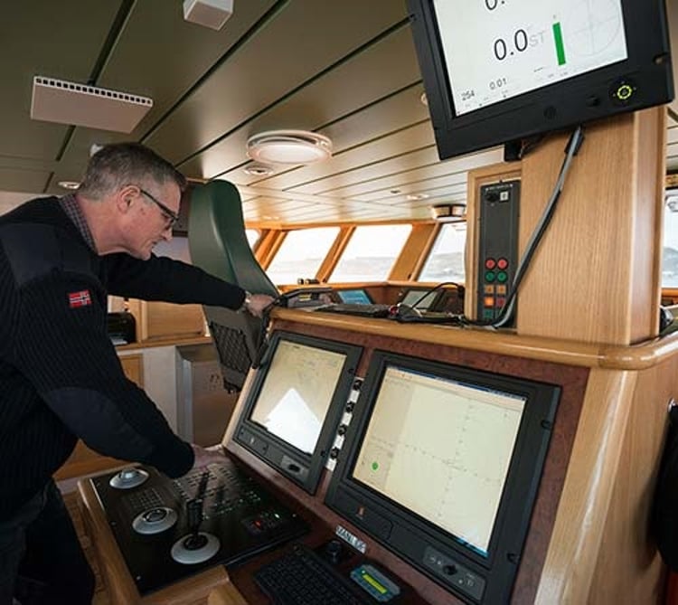
An Integrated Bridge System puts radar, ECDIS, conning display, autopilot and alarm management on shared workstations behind a common data bus, so one officer can stand a safe watch from a single console instead of walking between separate stand-alone instruments.
Read more — Bridge Integration System (IBS/INS) explained ▾
What sets an integrated bridge system apart
A conventional bridge has separate, independently wired instruments, a radar unit, an ECDIS terminal, an autopilot control head, a GPS repeater, each with its own display and its own failure mode. An Integrated Bridge System (IBS), sometimes certified to the stricter Integrated Navigation System (INS) performance standard, ties these functions together over a shared data network so that any workstation on the bridge can display any function: conning, radar overlay, chart, alarm status. The point is not just convenience; IMO performance standards (MSC.252(83) for INS) require that the integration does not create a single point of failure that takes down navigation entirely, so a properly built system still lets the watch officer fall back to independent stand-alone operation of each sensor if the integration layer itself fails.

Main components
Multifunction workstations
Identical or near-identical consoles that can each be configured to show radar, ECDIS, conning or alarm screens, reducing the number of unique spare parts on board compared with dedicated single-purpose units.
Sensor inputs
GPS, gyrocompass, speed log, echo sounder, AIS and wind sensors feed the network individually, with the IBS responsible for distributing and time-stamping their data consistently across every display.
Data network and switching
A redundant network backbone, often dual-redundant Ethernet, connects sensors to workstations; the switching architecture is what INS performance standards scrutinise most closely for single points of failure.
Alarm management system
A centralised alert handler collects and prioritises alarms from every connected sensor and subsystem so the watch officer sees one coherent alarm picture rather than competing individual alarms.
Conning display
A dedicated screen summarising heading, speed, rate of turn, rudder angle and engine data for close-quarters manoeuvring, usually positioned centrally regardless of which workstation the officer is otherwise using.
Selection and sizing
- Number of workstations against bridge layout and the number of watch officers expected to use them simultaneously in restricted waters.
- Whether INS certification to IMO MSC.252(83) is required by the flag state or intended trade, versus a lower-tier IBS that integrates functions without full INS redundancy.
- Compatibility with existing sensors if the project is a retrofit rather than a newbuild, since sensor age and interface protocol often force a wider replacement than planned.
- Software update and cyber security support arrangement, since a networked bridge carries the same patching obligations as any other networked system.
Regulations and class
SOLAS Chapter V sets carriage requirements for the individual navigation functions an IBS integrates. IMO performance standard MSC.252(83) applies specifically to Integrated Navigation Systems and defines the redundancy and independent-operation requirements referenced above. Classification societies survey the bridge equipment under their navigation and communication equipment rules, and IACS Unified Requirements address cyber resilience for networked bridge systems on newer tonnage. Type approval of the specific IBS/INS configuration, not just the individual sensors, is generally required before it can be fitted.
Typical faults
| Fault | Cause | Consequence |
|---|---|---|
| Workstation freeze or blank screen | Software fault or network switch failure | Loss of one display; officer must switch to another workstation or fall back to stand-alone mode |
| Sensor data mismatch between displays | Time synchronisation drift across the network | Conflicting position or heading readouts, watch officer confusion |
| Alarm flood | Alarm management thresholds not tuned to the vessel's actual sensor set | Officer desensitised to genuine alarms during heavy weather or port entry |
| Failure to revert to stand-alone mode | Fallback logic not tested since commissioning | Full navigation blackout if the integration layer fails |
What to look for in a supplier
- A demonstrated, tested procedure for falling back to stand-alone sensor operation, not just a claim that it exists.
- Type approval certificates matching the exact configuration being purchased, not a generic product line certificate.
- Training support for bridge teams, since an integrated system changes watchkeeping habits more than a single-instrument replacement does.
- A defined cyber security update path, given the networked architecture.
Test the fallback-to-stand-alone procedure on every workstation during a quiet passage, not just once at commissioning; officers who have never actually done it under pressure lose time in the one moment the integration layer fails and they need it most.
17 manufacturers · 126 models
Kongsberg Maritime
59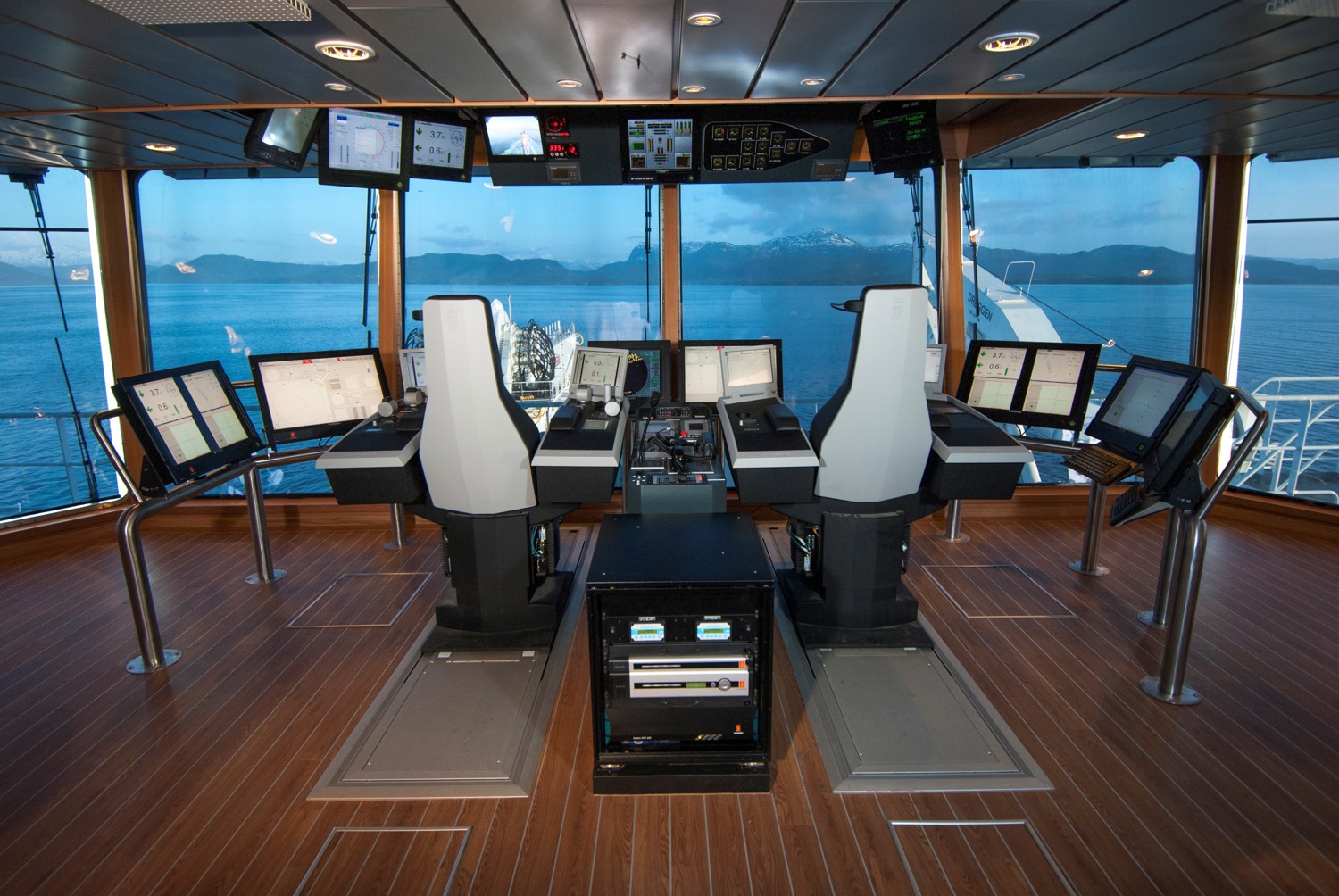
- Sensor, antenna or transducer fouling, damage or misalignment causes unstable, missing or inaccurate data
- Power-supply or processor faults cause resets, blank displays or complete loss of indication
- Cable, connector or network faults cause intermittent data or loss of outputs to dependent bridge systems
- Incorrect configuration or calibration causes persistent disagreement with independent references
- Display, storage or software faults cause frozen values, alarms or unavailable navigation functions
- Full IMO‑approved integration of navigation and DP functions
- Open, modular architecture allowing future sensor upgrades
- Proven on cruise ships, offshore supply vessels and naval platforms
- High‑resolution multi‑function displays with customizable layouts
- Supports redundant workstations for limited fault tolerance
- System bus is a single point of failure unless additional redundancy modules are added
- Workstation hardware ages quickly; refresh cycles can be costly
- Software license management adds administrative overhead
- Initial capital cost higher than basic standalone ECDIS/radar solutions
- Complex configuration may require specialised Kongsberg support
- Display/indicator failure due to electronics aging
- Sensor-Interface Kommunikationsfehler
- Software-/Firmware-Bugs erfordern Updates
- Antenna cable corrosion due to deck loading
- Voltage supply problems during electrical system fluctuations
- Modular architecture with hot‑standby redundancy for displays and processors
- Seamless K‑Steering integration enabling precise autopilot control
- User‑friendly multi‑touch interface with customizable screen layouts
- Regular software/firmware updates via manufacturer advisory to keep functionality current
- Class‑approved (DNV) and SOLAS compliant, simplifying certification for new builds
- Display electronics can degrade over time, leading to occasional screen failures
- Sensor interface communication errors reported in harsh vibration environments
- Frequent firmware updates required to address software bugs
- Antenna cabling prone to corrosion when exposed to deck load stresses
- Higher upfront cost and installation complexity compared with basic autopilot units
- Display/indicator failure due to electronics aging
- Sensor-Interface Kommunikationsfehler
- Software-/Firmware-Bugs erfordern Updates
- Antenna cable corrosion due to deck loading
- Voltage supply problems during electrical system fluctuations
- High level of integration reduces cabling and simplifies sensor management
- Modular architecture allows scalable expansion and easy retrofits
- Built‑in redundancy with dual displays and power supplies meets SOLAS requirements
- User‑friendly graphical interface supports multi‑crew operation and training
- Regular software updates from Kongsberg keep the system compliant with evolving regulations
- Significant upfront capital cost compared with stand‑alone navigation units
- Complex installation and commissioning require specialised engineering support
- Proprietary hardware/software can limit third‑party sensor compatibility without additional adapters
- Longer lead times for spare parts due to integrated design
- Ongoing licence fees for software updates and remote monitoring services
- Display/indicator failure due to electronics aging
- Sensor-Interface Kommunikationsfehler
- Software-/Firmware-Bugs erfordern Updates
- Antenna cable corrosion due to deck loading
- Voltage supply problems during electrical system fluctuations
- High level of sensor integration reduces operator workload and improves situational awareness
- Modular architecture allows easy expansion or replacement of individual components
- Built‑in redundancy (dual displays, redundant processors) meets SOLAS bridge requirements
- Class approvals (DNV) and IEC 60945 compliance simplify certification for new builds and retrofits
- Extensive support from Kongsberg with regular software/firmware updates
- Initial capital cost and installation effort are higher than stand‑alone ECDIS solutions
- Complexity requires specialised training for bridge crew and maintenance personnel
- Older hardware can suffer display failures or cable corrosion if not inspected regularly
- Software bugs have been reported, necessitating frequent firmware updates
- Integration with non‑Kongsberg sensors may require custom interface work
- Display/indicator failure due to electronics aging
- Sensor-Interface Kommunikationsfehler
- Software-/Firmware-Bugs erfordern Updates
- Antenna cable corrosion due to deck loading
- Voltage supply problems during electrical system fluctuations
- High resolution and low false‑alarm rate thanks to digital signal processing
- Seamless integration with Kongsberg Bridge Integration System (IBS/INS) via NMEA 2000/0183
- Advanced ARPA and automatic target tracking functions
- Modular design allows optional S‑band add‑on for enhanced weather detection
- DNV approved and widely accepted by classification societies
- Higher acquisition cost compared with basic radars from other vendors
- Requires Kongsberg bridge suite or compatible interface for full functionality
- Software/firmware updates are frequent and must be managed to avoid bugs
- Antenna cable corrosion reported in harsh deck‑load environments
- Sensitive to severe shipboard power fluctuations; may need voltage stabilisation
- Display/indicator failure due to electronics aging
- Sensor-Interface Kommunikationsfehler
- Software-/Firmware-Bugs erfordern Updates
- Antenna cable corrosion due to deck loading
- Voltage supply problems during electrical system fluctuations
- Modular architecture allows easy expansion or replacement of individual components.
- High redundancy with dual processors and backup displays to meet SOLAS requirements.
- Supports a wide range of sensors (radar, AIS, ECDIS, gyrocompass) via standardized interfaces.
- User‑friendly graphical interface reduces crew training time.
- Certified by DNV for compliance with IMO bridge standards.
- Electronic ageing can lead to display failures if not refreshed regularly.
- Sensor‑interface communication errors have been reported, requiring firmware updates.
- Antenna cable corrosion observed on vessels with heavy deck loads.
- Power supply fluctuations may cause intermittent system instability.
- Initial acquisition cost is higher than some competing IBS solutions.
- Display/indicator failure due to electronics aging
- Sensor-Interface Kommunikationsfehler
- Software-/Firmware-Bugs erfordern Updates
- Antenna cable corrosion due to deck loading
- Voltage supply problems during electrical system fluctuations
- Modular architecture allows easy expansion or replacement of individual sensor inputs.
- High redundancy with dual displays and fail‑over processing meets SOLAS requirements for critical navigation data.
- Unified user interface reduces crew workload and training time across multiple bridge subsystems.
- Remote diagnostics and OTA software updates simplify lifecycle support.
- Class‑approved (DNV) and IEC 60945 compliant, facilitating type approval processes.
- Higher upfront capital cost compared with stand‑alone navigation units.
- Complexity of integration can extend installation time on retrofit projects.
- Proprietary software updates are required regularly to address known firmware bugs.
- Display failures have been reported due to ageing electronics; spare displays increase inventory costs.
- Antennacable corrosion issues in harsh deck environments demand vigilant cable routing and protection.
- Display/indicator failure due to electronics aging
- Sensor-Interface Kommunikationsfehler
- Software-/Firmware-Bugs erfordern Updates
- Antenna cable corrosion due to deck loading
- Voltage supply problems during electrical system fluctuations
- High level of integration – ECDIS, radar, AIS, engine/auxiliary monitoring on one platform
- Modular architecture allows phased upgrades and easy addition of new sensors
- Class approvals (DNV, ABS) simplify SOLAS compliance and flag‑state surveys
- Proven field track record on a wide range of commercial vessels
- Comprehensive remote diagnostics and firmware update capability
- Older hardware generations can suffer display/electronics ageing issues
- Complexity may require specialised training for bridge crew and maintenance staff
- Software bugs have historically required frequent patch cycles
- Antenna cable routing is vulnerable to corrosion if not protected from deck loads
- Power‑quality sensitivity – voltage fluctuations on the ship’s bus can cause outages
- Display/indicator failure due to electronics aging
- Sensor-Interface Kommunikationsfehler
- Software-/Firmware-Bugs erfordern Updates
- Antenna cable corrosion due to deck loading
- Voltage supply problems during electrical system fluctuations
- Modular architecture allows easy addition or replacement of sensor interfaces (NMEA 0183, NMEA 2000, Ethernet).
- Dual‑redundant hardware and software layers meet SOLAS bridge‑watch requirements.
- Unified user interface reduces crew workload and improves situational awareness.
- Remote diagnostics and over‑the‑air firmware updates from Kongsberg support centre.
- Scalable from small ferries to large cruise ships and offshore vessels.
- Display units can suffer age‑related electronic failures (known display/display failure).
- Sensor interface communication errors have been reported, requiring careful cable routing and shielding.
- Software/firmware bugs occasionally necessitate unscheduled updates.
- Antenna cables are prone to corrosion when exposed to deck‑load stresses.
- Power‑supply fluctuations on the ship’s bus can cause intermittent system resets.
- Display/indicator failure due to electronics aging
- Sensor-Interface Kommunikationsfehler
- Software-/Firmware-Bugs erfordern Updates
- Antenna cable corrosion due to deck loading
- Voltage supply problems during electrical system fluctuations
- Highly modular – can be expanded with additional sensor inputs or display units without major redesign
- Proven reliability on large commercial vessels; integrates ECDIS, radar overlay, AIS, and autopilot data seamlessly
- Centralised software platform enables remote diagnostics and firmware updates from Kongsberg
- Scalable user interface that supports both 2‑monitor and multi‑screen bridge layouts
- Extensive class society approvals (e.g., DNV) simplify certification for newbuilds
- Higher capital cost compared with basic stand‑alone consoles
- Installation complexity – requires detailed wiring, network planning and integration engineering
- Proprietary software ecosystem; third‑party equipment may need adapters or custom interfaces
- Regular firmware updates are mandatory to address known bugs and security patches
- Obsolescence risk for older hardware generations if spare parts become scarce
- Display/indicator failure due to electronics aging
- Sensor-Interface Kommunikationsfehler
- Software-/Firmware-Bugs erfordern Updates
- Antenna cable corrosion due to deck loading
- Voltage supply problems during electrical system fluctuations
- Full sensor fusion (radar, AIS, ECDIS, GPS) with a single operator console
- Modular architecture allows phased upgrades and easy addition of new sensors
- Class‑approved redundancy and fail‑over handling for critical navigation data
- Proven Kongsberg software platform with regular security/firmware updates
- Streamlined cabling reduces installation time and deck‑space usage
- Higher upfront capital cost compared with basic ECDIS‑only solutions
- Complex integration may require specialised Kongsberg installers and training
- Proprietary software can limit third‑party hardware compatibility
- Known ageing of display electronics can lead to display failures if not refreshed
- Antennacable corrosion reported in harsh deck environments, requiring vigilant inspection
- Display/indicator failure due to electronics aging
- Sensor-Interface Kommunikationsfehler
- Software-/Firmware-Bugs erfordern Updates
- Antenna cable corrosion due to deck loading
- Voltage supply problems during electrical system fluctuations
- High level of sensor fusion – ECDIS, radar, AIS, gyrocompass and engine data can be displayed together
- Modular architecture allows incremental upgrades and easy addition of new sensors
- Redundant hardware configuration meets SOLAS bridge redundancy requirements
- User‑friendly graphical UI with customizable layouts reduces crew workload
- Supported by Kongsberg’s global service network and regular software advisories
- Complex installation – requires extensive cabling and integration engineering on newbuilds or retrofits
- Proprietary software may limit third‑party interoperability without additional adapters
- Electronic ageing can lead to display failures, as reported in field experience
- Antennacable corrosion observed when routing near deck loads; requires protective measures
- Sensitivity to shipboard power fluctuations; robust UPS or voltage conditioning often needed
- Display/indicator failure due to electronics aging
- Sensor-Interface Kommunikationsfehler
- Software-/Firmware-Bugs erfordern Updates
- Antenna cable corrosion due to deck loading
- Voltage supply problems during electrical system fluctuations
- High level of sensor fusion – all primary navigation and DP sensors are displayed on common screens, reducing operator workload.
- Modular architecture (DP, PM, DPM) allows scaling from simple positioning to full dynamic‑positioning without hardware replacement.
- cJoy joystick provides intuitive manual control for DP manoeuvring and emergency steering.
- Proven track record with major shipowners; extensive class approvals and long‑term support from Kongsberg.
- Remote software update capability via Kongsberg’s Fleet Management System (FMS) to keep firmware current.
- Complexity of installation – requires substantial cabling, antenna routing and integration engineering on new builds or retrofits.
- Dependence on proprietary Kongsberg hardware; third‑party replacements are limited.
- Software bugs have historically required frequent patches; operators must maintain a disciplined update schedule.
- Aging electronic modules can suffer display failures if not refreshed according to the manufacturer’s refresh cycle.
- Higher upfront cost compared with basic stand‑alone radar/ECDIS packages.
- Display/indicator failure due to electronics aging
- Sensor-Interface Kommunikationsfehler
- Software-/Firmware-Bugs erfordern Updates
- Antenna cable corrosion due to deck loading
- Voltage supply problems during electrical system fluctuations
- Real‑time remote diagnostics reduce vessel downtime
- Centralised firmware and software updates simplify fleet maintenance
- Seamless integration with multiple Kongsberg bridge sensors and displays
- Supports SOLAS reporting and compliance through automated data collection
- Analytics dashboards improve situational awareness and decision making
- Requires reliable satellite or broadband connectivity; performance degrades with poor link
- Subscription‑based pricing adds ongoing operational cost
- Vendor lock‑in – full functionality only with Kongsberg bridge equipment
- Potential cybersecurity exposure if network security is not rigorously managed
- Remote command latency can be an issue for time‑critical interventions
- Display/indicator failure due to electronics aging
- Sensor-Interface Kommunikationsfehler
- Software-/Firmware-Bugs erfordern Updates
- Antenna cable corrosion due to deck loading
- Voltage supply problems during electrical system fluctuations
- High‑level sensor fusion – radar, ECDIS, AIS, GPS, gyrocompass and more are displayed on a single workstation
- Modular architecture allows easy addition of new sensors or displays
- DNV‑approved design with built‑in redundancy for critical navigation functions
- User‑friendly graphical interface that can be customized per vessel class
- Remote software/firmware update capability via Kongsberg’s advisory service
- Complex system integration may require specialised engineering support during installation
- Higher upfront cost compared with basic stand‑alone radar/ECDIS packages
- Known ageing‑related display failures and sensor‑interface communication errors demand vigilant maintenance
- Antennacable corrosion risk in harsh deck environments; requires regular inspection
- Power‑supply sensitivity – voltage fluctuations on the ship’s bus can cause intermittent faults
- Display/indicator failure due to electronics aging
- Sensor-Interface Kommunikationsfehler
- Software-/Firmware-Bugs erfordern Updates
- Antenna cable corrosion due to deck loading
- Voltage supply problems during electrical system fluctuations
- High level of sensor integration reduces operator workload
- Modular architecture allows easy expansion and redundancy
- Class-approved (DNV) and SOLAS compliant out‑of‑the‑box
- Remote diagnostics and over‑the‑air software updates
- User‑friendly graphical interface with customizable layouts
- Complex installation and commissioning require specialised engineering support
- Higher capital cost compared to stand‑alone ECDIS units
- Software/firmware bugs have historically required frequent patches
- Aging electronic components can lead to display failures
- Antennacable corrosion risk in harsh deck environments
- Display/indicator failure due to electronics aging
- Sensor-Interface Kommunikationsfehler
- Software-/Firmware-Bugs erfordern Updates
- Antenna cable corrosion due to deck loading
- Voltage supply problems during electrical system fluctuations
- High‑resolution multi‑function display with configurable layouts
- Seamless integration with Kongsberg navigation suite (radar, ECDIS, AIS)
- Built‑in redundancy in LVD‑2 for increased reliability
- SOLAS‑compliant and DNV class approved
- Remote software/firmware update capability via manufacturer advisory
- Vendor‑specific ecosystem – limited interoperability with non‑Kongsberg systems
- Reported electronic ageing can cause display failures if not refreshed regularly
- Antennacable corrosion issues observed on vessels with high deck loads
- Requires quarterly sensor calibration and monthly backup‑system testing, adding maintenance workload
- Higher capital cost compared with generic bridge monitors
- Display/indicator failure due to electronics aging
- Sensor-Interface Kommunikationsfehler
- Software-/Firmware-Bugs erfordern Updates
- Antenna cable corrosion due to deck loading
- Voltage supply problems during electrical system fluctuations
- Highly modular – individual consoles can be added or removed without major rewiring
- Open architecture with NMEA 0183/2000 and Kongsberg proprietary interfaces for easy sensor integration
- Built‑in redundancy (dual power feeds, hot‑standby processors) meets SOLAS requirements
- Certified by DNV and compliant with IMO bridge standards, simplifying class approval on new builds
- User‑friendly GUI that can be customized per vessel operator
- Display units may suffer electronic ageing leading to occasional screen failures
- Sensor‑interface communication errors have been reported when cable routing is compromised
- Software/firmware bugs require regular manufacturer advisories and updates
- Antenna cables are prone to corrosion if exposed to deck loads or harsh marine environments
- Power quality issues on vessels with unstable board voltage can cause intermittent system resets
- Display/indicator failure due to electronics aging
- Sensor-Interface Kommunikationsfehler
- Software-/Firmware-Bugs erfordern Updates
- Antenna cable corrosion due to deck loading
- Voltage supply problems during electrical system fluctuations
- Modular, open architecture allows easy addition of new sensors or displays
- Built‑in redundancy (dual processors, hot‑swap displays) meets SOLAS requirements
- Kongsberg’s long track record and global support network
- Software can be updated remotely via manufacturer advisories
- Supports a wide range of third‑party equipment through standard interfaces
- Display units may suffer age‑related electronic failures (known display‑outage issue)
- Sensor interface communication errors reported if cabling is not regularly inspected
- Antennacable corrosion observed on decks with high mechanical load
- Power supply fluctuations can cause intermittent system resets
- Higher upfront cost and installation complexity compared with basic ECDIS only solutions
- Display/indicator failure due to electronics aging
- Sensor-Interface Kommunikationsfehler
- Software-/Firmware-Bugs erfordern Updates
- Antenna cable corrosion due to deck loading
- Voltage supply problems during electrical system fluctuations
- High level of sensor integration – radar, AIS, ECDIS, GPS, gyrocompass can be fused on one platform
- Redundant hardware architecture meets SOLAS requirements for critical navigation equipment
- Modular design allows easy addition or replacement of display units and I/O cards
- Kongsberg’s remote diagnostics and regular software‑update service keep the system current
- Proven DNV class approval, facilitating flag‑state acceptance
- Electronic components can age, leading to occasional display or interface failures as reported in field experience
- Antenna and sensor cabling on deck are prone to corrosion if not regularly inspected
- Software/firmware updates are mandatory and may require scheduled downtime
- Initial capital cost is higher than basic stand‑alone navigation units
- Proprietary hardware limits flexibility for vessels that prefer open‑architecture solutions
- Display/indicator failure due to electronics aging
- Sensor-Interface Kommunikationsfehler
- Software-/Firmware-Bugs erfordern Updates
- Antenna cable corrosion due to deck loading
- Voltage supply problems during electrical system fluctuations
- Modular sensor integration allows easy addition or replacement of navigation devices.
- Centralized multi‑function display reduces cockpit clutter and improves situational awareness.
- Supports over‑the‑air software updates via Kongsberg’s advisory system.
- Designed to meet SOLAS bridge inspection intervals, simplifying regulatory compliance.
- Display units can suffer electronic aging leading to loss of visual output.
- Sensor interface communication errors may occur under certain cable stress conditions.
- Frequent software/firmware updates are required to address bugs.
- Antenna cabling is prone to corrosion when exposed to deck load and marine environment.
- Sensitive to board‑network voltage fluctuations, causing occasional power supply issues.
- Display/indicator failure due to electronics aging
- Sensor-Interface Kommunikationsfehler
- Software-/Firmware-Bugs erfordern Updates
- Antenna cable corrosion due to deck loading
- Voltage supply problems during electrical system fluctuations
- Modular architecture allows easy addition of new sensors or display modules
- High-resolution multi‑function displays with customizable layouts
- Built‑in redundancy (dual processors and power supplies) enhances reliability
- Seamless integration with other Kongsberg maritime products (ECDIS, radar, autopilot)
- Supports remote software updates via manufacturer advisory
- Electronic components can age, leading to display failures if not refreshed regularly
- Sensor‑interface communication errors have been reported in harsh vibration environments
- Software/firmware bugs may require frequent patches and validation cycles
- Antenna cable corrosion observed when cables are routed under deck loads
- Voltage fluctuations on the ship’s power network can cause intermittent supply issues

- Display/indicator failure due to electronics aging
- Sensor-Interface Kommunikationsfehler
- Software-/Firmware-Bugs erfordern Updates
- Antenna cable corrosion due to deck loading
- Voltage supply problems during electrical system fluctuations
- High level of sensor fusion – multiple navigation sources displayed on one screen
- Modular architecture allows easy addition or replacement of sensors
- Redundant hardware options (dual displays, backup CPU) increase reliability
- User‑friendly GUI with customizable layouts and alarm management
- Certified to DNV standards and compliant with IMO bridge regulations
- Complex system requires specialised training for crew and maintenance staff
- Software must be kept up‑to‑date; firmware bugs have historically needed frequent patches
- Display electronics can degrade over time, leading to occasional screen failures
- Antennacable corrosion observed in harsh deck environments if not inspected regularly
- Higher upfront cost compared with basic standalone radar/ECDIS combos
- Display/indicator failure due to electronics aging
- Sensor-Interface Kommunikationsfehler
- Software-/Firmware-Bugs erfordern Updates
- Antenna cable corrosion due to deck loading
- Voltage supply problems during electrical system fluctuations
- Modular architecture enables easy addition or replacement of sensors and display units.
- Dual‑processor redundancy with backup display ensures continuous operation if a primary unit fails.
- Integrated ECDIS, AIS, radar and gyrocompass functions reduce cockpit clutter and simplify operator workload.
- DNV‑approved hardware designed for harsh marine environments provides proven reliability.
- Scalable software platform supports future upgrades and compliance with evolving regulations.
- Software/firmware updates often require specialized Kongsberg support and scheduled downtime.
- Reported antenna‑cable corrosion when cables are routed under deck loads, increasing maintenance effort.
- Higher capital cost compared with stand‑alone ECDIS or basic navigation displays.
- Maintenance intensive: quarterly sensor calibration and monthly backup‑system tests are mandatory.
- Older series units may experience display failures due to electronic component ageing.
- Display/indicator failure due to electronics aging
- Sensor-Interface Kommunikationsfehler
- Software-/Firmware-Bugs erfordern Updates
- Antenna cable corrosion due to deck loading
- Voltage supply problems during electrical system fluctuations
- Native integration with Kongsberg Azipull thrusters and other K‑Maritime sensors for seamless DP operation
- Modular console architecture allows scalable expansion of displays and input devices
- DNV‑approved design provides recognised class certification and compliance with SOLAS requirements
- Built‑in redundancy (dual power feeds, hot‑standby processors) enhances operational reliability
- Regular software‑update pathway from manufacturer ensures compatibility with latest navigation standards
- Electronic components can age, leading to occasional display or indicator failures if not refreshed
- Sensor‑interface communication errors have been reported when third‑party equipment is mixed with Kongsberg hardware
- Software/firmware bugs may require frequent updates and temporary system downtime during patching
- Antenna cabling on deck is prone to corrosion under harsh marine exposure, necessitating vigilant inspection
- Power‑supply fluctuations in the ship’s electrical network can cause occasional IBS instability
- Display/indicator failure due to electronics aging
- Sensor-Interface Kommunikationsfehler
- Software-/Firmware-Bugs erfordern Updates
- Antenna cable corrosion due to deck loading
- Voltage supply problems during electrical system fluctuations
- High‑level data fusion from multiple sensors into one coherent display
- Modular architecture allows easy addition or replacement of subsystems
- Kongsberg brand reputation with DNV approval for safety‑critical use
- Built‑in redundancy for critical displays and power supplies
- Manufacturer provides regular software/firmware updates via advisory
- Display failures reported due to electronic ageing of the units
- Sensor‑interface communication errors can arise, requiring specialist troubleshooting
- Software/firmware bugs may necessitate frequent update cycles
- Antenna cabling prone to corrosion when subjected to deck load stresses
- Sensitive to board voltage fluctuations; power‑supply issues reported in unstable networks
- Display/indicator failure due to electronics aging
- Sensor-Interface Kommunikationsfehler
- Software-/Firmware-Bugs erfordern Updates
- Antenna cable corrosion due to deck loading
- Voltage supply problems during electrical system fluctuations
- Modular architecture (DPN/DPD CP/FP, AUX CP/FP, ICE CP/FP) allows tailored configurations for DP, auxiliary and ice‑class functions.
- Full DNV‑GL approval with IEC 60945 compliance ensures class acceptance and regulatory conformity.
- High redundancy with dual displays and fail‑over processing reduces risk of total bridge outage.
- Integrated sensor fusion (radar, AIS, ECDIS, gyrocompass) simplifies operator workload and improves decision speed.
- Remote diagnostics and manufacturer‑provided software updates support lifecycle management.
- Initial capital cost is higher than stand‑alone ECDIS or basic bridge consoles.
- Complexity of the system demands specialised training for crew and maintenance personnel.
- Aging electronic components can lead to display failures if not refreshed according to service plan.
- Antennacable corrosion reported in harsh deck environments requires vigilant inspection.
- Power‑supply sensitivity; voltage fluctuations on the ship’s bus may cause intermittent faults.
- Display/indicator failure due to electronics aging
- Sensor-Interface Kommunikationsfehler
- Software-/Firmware-Bugs erfordern Updates
- Antenna cable corrosion due to deck loading
- Voltage supply problems during electrical system fluctuations
- Highly modular – core TT1300 can be expanded with DPN/DPD, AUX and ICE packages
- Full DP, CP and FP integration reduces operator workload and improves safety
- Proven reliability on a wide range of offshore and ice‑class vessels
- DNV class approved and SOLAS compliant displays
- User‑friendly HMIs with customizable layouts
- Display units can suffer age‑related electronic failures requiring replacement
- Sensor interface communication errors reported in harsh marine environments
- Software/firmware bugs necessitate frequent manufacturer advisories and updates
- Antenna cable corrosion observed where deck loads are high
- Sensitive to board‑network voltage fluctuations; robust power conditioning required
- Display/indicator failure due to electronics aging
- Sensor-Interface Kommunikationsfehler
- Software-/Firmware-Bugs erfordern Updates
- Antenna cable corrosion due to deck loading
- Voltage supply problems during electrical system fluctuations
- Unified hardware/software platform for DP, non‑DP and ice‑class modes reduces crew training needs
- Modular architecture allows easy addition of auxiliary or ice‑specific functions (AUX, ICE variants)
- High redundancy with dual processors and fail‑safe display units enhances safety at sea
- Native support for Kongsberg sensor suite simplifies integration and data consistency
- Regular manufacturer software advisories keep the system up‑to‑date with regulatory changes
- Complex installation and configuration can increase initial project cost and time
- Known display failures due to electronic ageing require proactive replacement cycles
- Sensor interface communication errors may arise if cabling is not protected from deck corrosion
- Frequent software/firmware updates demand disciplined change‑management procedures
- Power supply fluctuations on older vessels can cause intermittent system instability
- Display/indicator failure due to electronics aging
- Sensor-Interface Kommunikationsfehler
- Software-/Firmware-Bugs erfordern Updates
- Antenna cable corrosion due to deck loading
- Voltage supply problems during electrical system fluctuations
- High level of sensor integration (radar, ECDIS, AIS, gyrocompass, DP sensors) on a single platform
- Redundant architecture with separate DPN, AUX and ICE modules for increased reliability
- Proven track record on offshore supply vessels and DP‑class ships
- Standardised Kongsberg user interface reduces crew training time across fleet
- Supports automatic software updates via manufacturer advisory
- Complex installation requiring specialised Kongsberg engineering support
- Proprietary hardware limits flexibility for third‑party sensor integration
- Software/firmware bugs have historically required frequent patches
- Higher upfront cost compared with more generic bridge consoles
- Cable routing and antenna placement are critical to avoid corrosion and signal loss
- Display/indicator failure due to electronics aging
- Sensor-Interface Kommunikationsfehler
- Software-/Firmware-Bugs erfordern Updates
- Antenna cable corrosion due to deck loading
- Voltage supply problems during electrical system fluctuations
- Modular architecture allows customized configurations (DPN/DPD, AUX, ICE variants).
- Built-in redundancy with dual displays and power supplies enhances safety.
- Seamless integration of dynamic positioning control with navigation data.
- Ice‑class version (ICE CP/FP) certified for polar operations.
- Extensive Kongsberg support network and regular software update advisories.
- High initial capital cost and complex installation requirements.
- Aging electronic components can lead to display failures if not refreshed.
- Antennacable corrosion reported under deck load conditions.
- Frequent software/firmware updates needed to address bugs.
- Power‑supply sensitivity to shipboard voltage fluctuations.
- Display/indicator failure due to electronics aging
- Sensor-Interface Kommunikationsfehler
- Software-/Firmware-Bugs erfordern Updates
- Antenna cable corrosion due to deck loading
- Voltage supply problems during electrical system fluctuations
- High level of integration – navigation, DP, autopilot and ancillary data displayed on a single console
- Redundant display modules (CP/FP) increase reliability for critical operations
- Modular variants (DPN/DPD, AUX, ICE) allow tailoring to vessel class and operating environment
- Proven DNV‑approved design with extensive offshore service history
- Supports IEC 61162 (NMEA 2000) data standards for seamless sensor integration
- Complex system architecture requires specialised training for crew and maintenance staff
- Higher upfront cost compared with stand‑alone navigation units
- Software/firmware updates are frequent and must be managed to avoid downtime
- Cable routing on deck can be vulnerable to corrosion if not inspected regularly
- Power quality sensitivity – voltage fluctuations may cause intermittent display failures

- Display/indicator failure due to electronics aging
- Sensor-Interface Kommunikationsfehler
- Software-/Firmware-Bugs erfordern Updates
- Antenna cable corrosion due to deck loading
- Voltage supply problems during electrical system fluctuations
- Full integration of navigation sensors, DP controller and auxiliary displays in one chassis
- Modular architecture allows easy addition of CP/FP or ICE interfaces as vessel requirements evolve
- Built‑in redundancy (dual power supplies, hot‑swap modules) meets SOLAS and class reliability standards
- Kongsberg’s proven software suite provides advanced route planning, collision avoidance and DP monitoring
- Extensive DNV approval history simplifies class certification for new builds or retrofits
- High upfront capital cost compared with basic ECDIS‑only solutions
- Complex installation and commissioning require Kongsberg‑trained personnel
- Proprietary hardware can limit third‑party sensor integration without additional adapters
- Software updates are frequent; missed patches may expose known bugs or security issues
- Physical footprint and weight may be restrictive on smaller vessels with limited bridge space
- Display/indicator failure due to electronics aging
- Sensor-Interface Kommunikationsfehler
- Software-/Firmware-Bugs erfordern Updates
- Antenna cable corrosion due to deck loading
- Voltage supply problems during electrical system fluctuations
- Full integration of navigation, DP control and auxiliary displays reduces cockpit clutter and wiring complexity
- Modular architecture allows configuration for DPN/DPD, auxiliary and ice‑class versions on the same hardware platform
- Proven class approval (DNV) and extensive field experience on offshore DP vessels
- High redundancy with dual CPUs and separate power supplies enhances reliability in harsh environments
- Supports a wide range of sensors and interfaces (radar, ECDIS, gyrocompass, AIS, etc.)
- Complex system requires specialised training for bridge crew and maintenance personnel
- Software/firmware updates are frequent to address bugs; failure to keep current can affect functionality
- Cable routing on deck is critical – corrosion of antenna cables has been reported in high‑stress installations
- Power supply sensitivity: voltage fluctuations on the ship’s network may cause intermittent failures
- Higher upfront cost compared with stand‑alone navigation consoles
- Display/indicator failure due to electronics aging
- Sensor-Interface Kommunikationsfehler
- Software-/Firmware-Bugs erfordern Updates
- Antenna cable corrosion due to deck loading
- Voltage supply problems during electrical system fluctuations
- Full integration of DP, navigation and auxiliary sensors on one HMI reduces crew workload
- Modular architecture allows scalable upgrades (DPN/DPD, AUX, ICE) without major rewiring
- Redundant processors and power supplies meet SOLAS/DNV safety requirements
- User‑friendly touchscreen interface with customizable layouts for different vessel classes
- Supports a wide range of Kongsberg and third‑party sensors through standardized interfaces
- High upfront cost and extensive installation effort compared with basic ECDIS solutions
- Complexity requires specialised training and certification for operators and maintainers
- Proprietary hardware can limit integration of non‑Kongsberg equipment without adapters
- Known ageing of display electronics may lead to occasional screen failures
- Antenna cable corrosion reported in harsh deck environments, increasing maintenance
- Display/indicator failure due to electronics aging
- Sensor-Interface Kommunikationsfehler
- Software-/Firmware-Bugs erfordern Updates
- Antenna cable corrosion due to deck loading
- Voltage supply problems during electrical system fluctuations
- Highly integrated solution combining navigation, communications and DP on a single platform
- Modular design (CP/FP variants) allows configuration for standard, auxiliary or ice‑class vessels
- Proven track record on offshore support ships, drillships and FPSOs
- Kongsberg’s extensive service network provides regular software updates and field support
- Supports both DP2 and DP3 configurations with redundancy options
- Complex system requires specialised training for crew and maintenance staff
- Electronic components are prone to age‑related display failures if not refreshed regularly
- Antenna cable routing on deck can suffer corrosion, especially in harsh marine environments
- Sensitive to shipboard power quality; voltage fluctuations may cause intermittent faults
- Software/firmware bugs occasionally necessitate urgent patches
- Display/indicator failure due to electronics aging
- Sensor-Interface Kommunikationsfehler
- Software-/Firmware-Bugs erfordern Updates
- Antenna cable corrosion due to deck loading
- Voltage supply problems during electrical system fluctuations
- Full integration of ECDIS, radar, AIS, gyrocompass and DP control in one HMI reduces crew workload
- Modular architecture (DPN/DPD CP/FP, AUX CP/FP, ICE CP/FP) allows phased upgrades and tailored configurations
- Proven redundancy with dual processors and hot‑standby units meets SOLAS and DP class requirements
- Extensive sensor support and open interfaces simplify integration of legacy equipment
- Kongsberg’s long service history provides a large knowledge base and worldwide support network
- High upfront capital cost compared with basic bridge consoles
- Complex installation and commissioning require specialised Kongsberg engineers
- Software/firmware updates must be tightly managed to avoid compatibility issues
- Older installations may experience display failures due to component ageing
- Cable routing on deck can be vulnerable to corrosion if not protected
- Display/indicator failure due to electronics aging
- Sensor-Interface Kommunikationsfehler
- Software-/Firmware-Bugs erfordern Updates
- Antenna cable corrosion due to deck loading
- Voltage supply problems during electrical system fluctuations
- High level of integration – combines radar, ECDIS, AIS, gyrocompass and engine monitoring in one UI
- Modular architecture allows easy addition or replacement of sensors and displays
- DNV‑approved design with built‑in redundancy for critical navigation functions
- Regular software‑update cycle from Kongsberg ensures compliance with the latest IMO regulations
- User‑friendly touchscreen interface reduces crew training time
- Display electronics can degrade over time, leading to occasional screen failures
- Sensor‑interface communication errors have been reported when legacy equipment is connected
- Software/firmware bugs may require frequent updates and temporary downtime
- Antenna cabling on the deck is prone to corrosion under heavy mechanical load
- Power supply fluctuations on board can cause intermittent system instability
- Display/indicator failure due to electronics aging
- Sensor-Interface Kommunikationsfehler
- Software-/Firmware-Bugs erfordern Updates
- Antenna cable corrosion due to deck loading
- Voltage supply problems during electrical system fluctuations
- Consolidates multiple navigation sensors on one display, reducing cockpit clutter
- High‑resolution 3‑D rendering improves target perception and collision avoidance
- Modular architecture allows easy addition of new sensor inputs or software upgrades
- Kongsberg’s proven reliability and extensive support network for marine bridge equipment
- Built‑in redundancy options (dual processors, backup power) to meet SOLAS requirements
- Higher upfront cost compared with stand‑alone radar/ECDIS units
- Complex integration may require specialised engineering support during installation
- Known issues with aging electronics can cause display failures if not refreshed regularly
- Cable routing on deck is prone to corrosion, demanding vigilant maintenance
- Software/firmware bugs occasionally necessitate urgent manufacturer advisories
- Display/indicator failure due to electronics aging
- Sensor-Interface Kommunikationsfehler
- Software-/Firmware-Bugs erfordern Updates
- Antenna cable corrosion due to deck loading
- Voltage supply problems during electrical system fluctuations
- Modular architecture allows easy addition or replacement of sensors and displays.
- Built‑in redundancy (dual processors, backup display) meets SOLAS bridge requirements.
- DNV approved and fully compliant with IMO/Flag State inspection regimes.
- Touchscreen HMIs provide intuitive control and reduce crew workload.
- Remote diagnostics and OTA software updates from Kongsberg simplify lifecycle support.
- Electronic components are prone to age‑related display failures if not refreshed regularly.
- Sensor‑interface communication errors can arise from cable wear or corrosion on deck runs.
- Requires quarterly sensor calibration and monthly backup‑system testing, increasing maintenance workload.
- Higher upfront cost compared with basic stand‑alone radar/ECDIS packages.
- Software/firmware bugs may necessitate frequent vendor advisories and updates.
- Display/indicator failure due to electronics aging
- Sensor-Interface Kommunikationsfehler
- Software-/Firmware-Bugs erfordern Updates
- Antenna cable corrosion due to deck loading
- Voltage supply problems during electrical system fluctuations
- Full sensor fusion reduces crew workload and improves decision speed
- Modular architecture allows addition of Kongsberg or third‑party sensors without major redesign
- High‑resolution multi‑function displays with customizable layouts
- Proven class approval (DNV) simplifies certification for new builds and retrofits
- Remote diagnostics and OTA software updates from Kongsberg support
- Complex system integration requires specialised installation and training
- Reliance on a single IT platform can create a single point of failure if not backed up
- Frequent firmware updates needed to address known bugs and sensor‑interface issues
- Antennacable corrosion reported in harsh deck environments; requires vigilant inspection
- Higher upfront cost compared with basic stand‑alone ECDIS or radar units
- Display/indicator failure due to electronics aging
- Sensor-Interface Kommunikationsfehler
- Software-/Firmware-Bugs erfordern Updates
- Antenna cable corrosion due to deck loading
- Voltage supply problems during electrical system fluctuations
- High level of integration reduces crew workload and improves situational awareness
- Modular architecture allows selective upgrade of displays or sensors
- Built‑in redundancy (dual processors, backup power) meets SOLAS requirements
- User‑friendly GUI with customizable layouts for different vessel operations
- Kongsberg’s extensive support network and regular software advisories
- Complex system requires specialised training for installation and maintenance
- Aging electronic components can lead to display failures if not refreshed
- Sensor interface communication errors reported when cabling is exposed to deck corrosion
- Frequent software/firmware updates are mandatory to keep certifications valid
- Initial capital cost higher than basic standalone ECDIS solutions
- Display/indicator failure due to electronics aging
- Sensor-Interface Kommunikationsfehler
- Software-/Firmware-Bugs erfordern Updates
- Antenna cable corrosion due to deck loading
- Voltage supply problems during electrical system fluctuations
- Modular sensor integration allowing easy addition of radar, AIS, ECDIS, etc.
- Supports redundant display units for high availability on the bridge.
- User‑configurable graphical interface that can be tailored to vessel operations.
- Designed to meet SOLAS and IEC bridge equipment standards.
- Kongsberg’s reputation for robust marine electronics and long‑term support.
- Display/electronic ageing can cause screen failures if not refreshed regularly.
- Sensor‑interface communication errors have been reported in harsh electromagnetic environments.
- Software/firmware bugs require periodic manufacturer advisories and updates.
- Antenna cabling is prone to corrosion when exposed to deck load stresses.
- Power supply fluctuations on the ship can affect system stability.
- Display/indicator failure due to electronics aging
- Sensor-Interface Kommunikationsfehler
- Software-/Firmware-Bugs erfordern Updates
- Antenna cable corrosion due to deck loading
- Voltage supply problems during electrical system fluctuations
- Modular architecture allows easy addition or replacement of sensors and display units
- Integrated with Kongsberg’s NAVNET‑X suite for seamless data sharing across navigation equipment
- DNV‑approved hardware meets SOLAS bridge requirements out‑of‑the‑box
- User‑friendly HMIs with customizable screen layouts reduce crew workload
- Scalable from small feeder vessels to large tankers, supporting both legacy and modern sensors
- Display electronics can suffer age‑related failures requiring periodic replacement
- Sensor‑interface communication errors have been reported if cable routing is not carefully managed
- Frequent software/firmware updates are needed to address known bugs
- Antenna cables are prone to corrosion when exposed to deck loads and harsh marine environments
- Power supply stability issues may arise with significant board‑network voltage fluctuations
- Display/indicator failure due to electronics aging
- Sensor-Interface Kommunikationsfehler
- Software-/Firmware-Bugs erfordern Updates
- Antenna cable corrosion due to deck loading
- Voltage supply problems during electrical system fluctuations
- Integrated sensor fusion reduces operator workload and improves situational awareness
- Redundant processing units provide high availability for critical navigation functions
- Designed to meet SOLAS and flag‑state inspection requirements out of the box
- Remote software/firmware update capability via manufacturer advisories
- Modular I/O allows easy addition or replacement of sensors and displays
- Display units can suffer electronic ageing leading to display failures
- Sensor interface communication errors have been reported in harsh marine environments
- Software/firmware bugs may require frequent updates to maintain stability
- Antenna cables are prone to corrosion when exposed to deck load stresses
- Voltage fluctuations on the ship’s power network can cause supply problems
- Display/indicator failure due to electronics aging
- Sensor-Interface Kommunikationsfehler
- Software-/Firmware-Bugs erfordern Updates
- Antenna cable corrosion due to deck loading
- Voltage supply problems during electrical system fluctuations
- Modular architecture allows easy addition or replacement of sensors and displays.
- Class‑approved by DNV, providing documented compliance with SOLAS requirements.
- Touchscreen HMIs with customizable layouts improve situational awareness.
- Built‑in redundancy with a backup system that can be tested monthly.
- Extensive support for Kongsberg’s own navigation suite (e.g., Radar, ECDIS) ensures seamless data exchange.
- Higher upfront capital cost compared with basic standalone displays.
- Complex network configuration; requires specialised training for installation and maintenance.
- Software/firmware updates are frequent to address bugs, increasing downtime risk if not managed.
- Antennacable corrosion reported in harsh deck environments can affect sensor interfaces.
- Limited native compatibility with non‑Kongsberg legacy bridge equipment without additional adapters.

- Display/indicator failure due to electronics aging
- Sensor-Interface Kommunikationsfehler
- Software-/Firmware-Bugs erfordern Updates
- Antenna cable corrosion due to deck loading
- Voltage supply problems during electrical system fluctuations
- High level of sensor integration reduces cabling and simplifies installation
- Modular architecture allows easy expansion or replacement of components
- Redundant display and processing units meet SOLAS requirements for safety
- User‑friendly common GUI across ECDIS, radar, AIS and autopilot functions
- Supported by Kongsberg’s global service network and regular software updates
- Higher upfront cost compared with basic stand‑alone navigation suites
- Complexity requires specialised training for bridge crew and maintenance staff
- Aging electronics can lead to display failures if not refreshed periodically
- Antenna cable corrosion reported in harsh deck environments
- Power quality sensitivity may cause intermittent faults on vessels with unstable board voltage
- Display/indicator failure due to electronics aging
- Sensor-Interface Kommunikationsfehler
- Software-/Firmware-Bugs erfordern Updates
- Antenna cable corrosion due to deck loading
- Voltage supply problems during electrical system fluctuations
- Modular architecture allows easy addition or replacement of sensors and display units
- Class‑approved by DNV, facilitating compliance with SOLAS and flag‑state requirements
- Advanced sensor fusion delivers a single, coherent navigation picture on multiple high‑resolution displays
- User‑friendly HMIs with customizable layouts reduce crew training time
- Remote diagnostics and firmware management via Kongsberg’s ServiceLink platform
- Display units can suffer from age‑related electronic failures (display/display failure)
- Sensor interface communication errors have been reported, requiring careful cable routing and shielding
- Software/firmware bugs may necessitate frequent updates to maintain stability
- Antenna cables are prone to corrosion when exposed to deck loads or harsh marine environments
- Power‑supply fluctuations on the ship’s electrical network can cause intermittent system outages
- Display/indicator failure due to electronics aging
- Sensor-Interface Kommunikationsfehler
- Software-/Firmware-Bugs erfordern Updates
- Antenna cable corrosion due to deck loading
- Voltage supply problems during electrical system fluctuations
- High level of sensor integration reduces cockpit clutter and simplifies operator workflow.
- Modular display configuration (3‑screen or B‑variant) adapts to different bridge sizes and layouts.
- Class approvals and SOLAS compliance are built‑in, easing certification for new builds and retrofits.
- Remote software/firmware update capability via Kongsberg advisories extends system life.
- Redundant power inputs and fault‑tolerant architecture improve operational reliability.
- Electronic components can age, leading to display failures that require periodic hardware refreshes.
- Antenna cable corrosion has been reported in harsh marine environments, increasing maintenance effort.
- Complex sensor interface may need specialised engineering support for troubleshooting communication errors.
- Software bugs occasionally surface, necessitating urgent firmware patches.
- Higher capital cost compared with basic stand‑alone ECDIS solutions.
- Display/indicator failure due to electronics aging
- Sensor-Interface Kommunikationsfehler
- Software-/Firmware-Bugs erfordern Updates
- Antenna cable corrosion due to deck loading
- Voltage supply problems during electrical system fluctuations
- Full sensor fusion on a single display reduces crew workload
- Modular architecture allows phased upgrades and easy replacement of faulty units
- Built‑in redundancy meets SOLAS bridge survivability requirements
- Remote diagnostics and manufacturer software‑update service
- Certified for DNV class and IMO Performance Standard D‑2
- Display electronics can age, leading to occasional screen failures
- Sensor interface communication errors reported in harsh marine environments
- Firmware bugs may require frequent updates from the vendor
- Antenna cable corrosion observed when deck loads are high
- Power supply sensitivity to board‑network voltage fluctuations
- Display/indicator failure due to electronics aging
- Sensor-Interface Kommunikationsfehler
- Software-/Firmware-Bugs erfordern Updates
- Antenna cable corrosion due to deck loading
- Voltage supply problems during electrical system fluctuations
- Modular architecture allows easy addition or replacement of sensor inputs (radar, AIS, ECDIS, etc.)
- High redundancy with dual‑redundant processors and power supplies to meet SOLAS requirements
- Proven DNV class approval and extensive field experience on a variety of vessel types
- User‑friendly graphical interface that can be customized for operator preferences
- Regular software/firmware update path from Kongsberg ensures compliance with new regulations
- Older hardware generations may suffer display/electronics ageing leading to occasional failures
- Complex sensor‑interface wiring can be prone to corrosion if antenna cables are not protected on deck
- Software bugs have required frequent firmware patches in past releases
- Power supply sensitivity to board voltage fluctuations may need additional conditioning equipment
- Initial installation cost and integration effort higher than some off‑the‑shelf display units
- Display/indicator failure due to electronics aging
- Sensor-Interface Kommunikationsfehler
- Software-/Firmware-Bugs erfordern Updates
- Antenna cable corrosion due to deck loading
- Voltage supply problems during electrical system fluctuations
- Modular architecture allows easy addition or replacement of sensors
- Redundant processing and power paths meet SOLAS safety requirements
- Class‑approved (DNV) with IEC 60945 compliance for marine navigation equipment
- Supports a wide range of sensor interfaces (NMEA 0183/2000, Ethernet, ARINC)
- Remote software update capability via manufacturer advisory
- Display units can suffer electronic ageing leading to screen failures
- Sensor‑interface communication errors reported in harsh vibration environments
- Frequent firmware patches required to resolve software bugs
- Antenna cabling prone to corrosion when exposed to deck loads and moisture
- Sensitive to board‑voltage fluctuations; requires stable power conditioning
- Display/indicator failure due to electronics aging
- Sensor-Interface Kommunikationsfehler
- Software-/Firmware-Bugs erfordern Updates
- Antenna cable corrosion due to deck loading
- Voltage supply problems during electrical system fluctuations
- High level of integration – multiple sensor inputs (gyrocompass, RPM, etc.) displayed on unified screens
- Modular architecture allows selective replacement or upgrade of individual units (SLIO, CCN, BU, etc.)
- Proven class approval – DNV certified for a wide range of vessel types
- User‑friendly interface with customizable layouts and alarm management
- Built‑in redundancy and backup testing procedures support SOLAS compliance
- Complex installation and commissioning require experienced Kongsberg installers
- Software updates are frequent; missed patches can lead to firmware bugs
- Antenna cable corrosion reported in harsh deck environments, increasing maintenance effort
- Higher upfront cost compared with basic stand‑alone radar/ECDIS solutions
- Dependence on proprietary hardware may limit third‑party integration
- Display/indicator failure due to electronics aging
- Sensor-Interface Kommunikationsfehler
- Software-/Firmware-Bugs erfordern Updates
- Antenna cable corrosion due to deck loading
- Voltage supply problems during electrical system fluctuations
- High level of sensor integration reduces cabling and operator workload
- Proven Kongsberg reliability with extensive field service network
- Modular architecture allows selective addition of radar, AIS, ECDIS etc.
- Built‑in redundancy for critical displays and power supplies
- Compliant with SOLAS bridge requirements and DNV approval
- Older electronics can suffer display failures as components age
- Sensor interface communication errors reported in harsh marine environments
- Frequent software/firmware updates required to address bugs
- Antenna cable corrosion observed when deck loads stress the routing
- Power‑supply sensitivity to board voltage fluctuations may cause outages
- Display/indicator failure due to electronics aging
- Sensor-Interface Kommunikationsfehler
- Software-/Firmware-Bugs erfordern Updates
- Antenna cable corrosion due to deck loading
- Voltage supply problems during electrical system fluctuations
- Open architecture supports NMEA 0183/2000, CAN and proprietary Kongsberg interfaces for easy sensor integration
- Redundant processor and display modules meet SOLAS requirements for bridge survivability
- Modular software allows custom screen layouts and rapid addition of new sensors via firmware updates
- Integrated alarm management and automatic route transfer improve safety on complex voyages
- Kongsberg’s global support network provides 24/7 field service and regular software advisories
- Higher initial capital cost compared with standalone radar or ECDIS units
- Complex configuration may require specialised engineering support during installation
- Known ageing‑related display failures; replacement parts can be expensive
- Cable routing on deck must be carefully managed to avoid corrosion of antenna cables under load
- Power fluctuations in the ship’s bus can cause occasional system resets if not properly filtered
- Display/indicator failure due to electronics aging
- Sensor-Interface Kommunikationsfehler
- Software-/Firmware-Bugs erfordern Updates
- Antenna cable corrosion due to deck loading
- Voltage supply problems during electrical system fluctuations
- Modular architecture allows easy addition or replacement of sensor interfaces and display units.
- High redundancy (dual processors, dual power feeds) meets SOLAS requirements for bridge systems.
- Native support for NMEA 2000, IEC 61162‑1/2 and Kongsberg’s own sensor suites simplifies integration with existing equipment.
- User‑friendly GUI with customizable screen layouts and route planning tools reduces crew workload.
- DNV‑approved design provides class society confidence for newbuilds and major retrofits.
- Older units have reported display failures linked to electronic component ageing.
- Sensor‑interface communication errors can arise if firmware is not kept up‑to‑date.
- Antenna cable corrosion has been observed in installations where deck loading stresses the cabling.
- Power supply disturbances on the ship’s electrical network may cause intermittent system resets.
- Software/firmware bugs occasionally require urgent manufacturer advisories and downtime for updates.

- Display/indicator failure due to electronics aging
- Sensor-Interface Kommunikationsfehler
- Software-/Firmware-Bugs erfordern Updates
- Antenna cable corrosion due to deck loading
- Voltage supply problems during electrical system fluctuations
- Highly modular – supports a wide range of Kongsberg and third‑party sensors via standardized interfaces
- Redundant architecture with dual processors and hot‑swap displays to meet SOLAS requirements
- User‑friendly graphical interface that can be customized for different vessel operations
- Proven track record on commercial vessels; DNV‑approved and IMO compliant
- Regular software/firmware updates from Kongsberg improve functionality and security
- Display units are prone to age‑related electronic failures, requiring periodic replacement
- Sensor interface communication errors have been reported when cabling is stressed or corroded
- Firmware bugs occasionally necessitate urgent patches, causing short downtimes
- Antenna and cable routing on deck can suffer corrosion if not protected against marine exposure
- Higher upfront cost and complexity of installation compared with basic stand‑alone radar/plotters
- Display/indicator failure due to electronics aging
- Sensor-Interface Kommunikationsfehler
- Software-/Firmware-Bugs erfordern Updates
- Antenna cable corrosion due to deck loading
- Voltage supply problems during electrical system fluctuations
- High level of sensor fusion reduces operator workload and improves situational awareness
- Redundant architecture with hot‑standby processors meets SOLAS redundancy requirements
- Scalable hardware allows addition of new sensors (e.g., ARPA, weather radar) without major re‑engineering
- User‑configurable workstations support both 2‑monitor and 4‑monitor layouts for large bridge spaces
- Kongsberg’s long‑track record ensures robust field support and regular firmware updates
- Initial capital cost higher than basic standalone radar/ECDIS combos
- Complexity of integration can extend installation time on retrofit projects
- Requires periodic software licensing for advanced modules (e.g., ARPA, predictive route planning)
- Dependence on proprietary Kongsberg hardware may limit third‑party sensor compatibility without custom interfaces
- Display/indicator failure due to electronics aging
- Sensor-Interface Kommunikationsfehler
- Software-/Firmware-Bugs erfordern Updates
- Antenna cable corrosion due to deck loading
- Voltage supply problems during electrical system fluctuations
- High level of integration – ECDIS, radar, AIS, autopilot and engine control can be displayed on one console
- Modular architecture allows incremental upgrades and easy replacement of individual sensor interfaces
- Redundant processor and power modules meet SOLAS requirements for bridge survivability
- User‑configurable screens and touch input improve crew ergonomics and reduce training time
- Widely accepted by classification societies (DNV, ABS) facilitating class approval
- Older electronic components are prone to display failures as noted in field reports
- Frequent software/firmware updates required to address bugs and maintain compatibility with new sensors
- Antenna cable corrosion reported when cables are routed under deck loads, increasing maintenance effort
- Power quality sensitivity – voltage fluctuations on the ship’s bus can cause intermittent outages
- Initial capital cost higher than basic stand‑alone navigation units
Consilium Marine & Safety
39
- Display/indicator failure due to electronics aging
- Sensor-Interface Kommunikationsfehler
- Software-/Firmware-Bugs erfordern Updates
- Antenna cable corrosion due to deck loading
- Voltage supply problems during electrical system fluctuations
- Modular architecture allows addition or replacement of sensor inputs without major rewiring
- Single‑screen presentation simplifies bridge watchkeeping and reduces clutter
- Supports remote firmware updates via manufacturer advisory
- Designed to meet SOLAS bridge equipment requirements
- Display electronics prone to age‑related failures requiring replacement
- Sensor interface communication errors reported in field service notes
- Frequent software/firmware patches needed to resolve bugs
- Antenna cabling susceptible to corrosion under deck load conditions
- Voltage fluctuations on the ship’s power network can cause supply problems
- Display/indicator failure due to electronics aging
- Sensor-Interface Kommunikationsfehler
- Software-/Firmware-Bugs erfordern Updates
- Antenna cable corrosion due to deck loading
- Voltage supply problems during electrical system fluctuations
- Single‑screen consolidation of multiple navigation sensors reduces crew workload.
- Modular architecture permits easy addition or replacement of sensor interfaces.
- Built‑in diagnostics support the mandatory SOLAS/Flag State annual inspection cycle.
- Manufacturer provides remote software‑update advisories for firmware bugs.
- Monthly backup‑system test ensures redundancy in case of primary display failure.
- Display electronics can fail with age, leading to costly replacements.
- Sensor‑interface communication errors have been reported under harsh conditions.
- Frequent firmware updates may be required to address software bugs.
- Antenna cabling is prone to corrosion when subjected to deck load stresses.
- Sensitivity to shipboard voltage fluctuations can cause power‑related malfunctions.

- Display/indicator failure due to electronics aging
- Sensor-Interface Kommunikationsfehler
- Software-/Firmware-Bugs erfordern Updates
- Antenna cable corrosion due to deck loading
- Voltage supply problems during electrical system fluctuations
- Modular architecture allows easy addition or replacement of navigation sensors
- Centralised multi‑sensor display reduces crew workload and improves situational awareness
- Supports over‑the‑air firmware updates and remote diagnostics per manufacturer advisory
- Designed for compliance with SOLAS bridge requirements and IEC 60945 standards
- Quarterly sensor calibration procedures are defined, facilitating regulatory inspections
- Electronic components show age‑related display failures if not refreshed regularly
- Sensor interface communication errors have been reported, requiring firmware patches
- Antenna cabling is prone to corrosion under deck load, necessitating periodic inspection
- Power supply fluctuations on the ship can cause intermittent system instability
- Frequent software/firmware updates increase maintenance workload and may need scheduled downtime
- Display/indicator failure due to electronics aging
- Sensor-Interface Kommunikationsfehler
- Software-/Firmware-Bugs erfordern Updates
- Antenna cable corrosion due to deck loading
- Voltage supply problems during electrical system fluctuations
- Unified display of radar, AIS, ECDIS and other sensor data reduces operator workload
- Modular architecture allows easy addition or replacement of sensors
- Meets SOLAS bridge equipment requirements and is DNV approved
- Remote software/firmware update capability via manufacturer advisory
- Built‑in backup system with monthly test procedure for redundancy
- Display electronics can age, leading to occasional screen failures
- Sensor interface communication errors have been reported in harsh marine environments
- Frequent software/firmware updates are required to fix bugs and maintain compliance
- Antenna cabling is prone to corrosion when exposed to deck load stresses
- Power supply fluctuations on the shipboard network can cause intermittent outages
- Display/indicator failure due to electronics aging
- Sensor-Interface Kommunikationsfehler
- Software-/Firmware-Bugs erfordern Updates
- Antenna cable corrosion due to deck loading
- Voltage supply problems during electrical system fluctuations
- Open architecture allows easy addition of new sensors or software modules
- Redundant processor and power paths meet SOLAS requirements for critical bridge equipment
- Integrated alarm management reduces operator workload and improves situational awareness
- Factory‑tested hardware with pre‑certified interfaces simplifies installation on new builds
- Supports both NMEA 0183 and NMEA 2000, enabling compatibility with a wide range of legacy sensors
- Display units have shown age‑related electronic failures; replacement may be required after several years
- Sensor interface communication errors reported when cable routing is exposed to deck loading or corrosion
- Frequent firmware patches are needed to resolve software bugs, increasing maintenance workload
- Power supply stability is critical; voltage fluctuations on the ship’s bus can cause system resets
- Monthly backup‑system testing and quarterly sensor calibration add operational overhead

- Display/indicator failure due to electronics aging
- Sensor-Interface Kommunikationsfehler
- Software-/Firmware-Bugs erfordern Updates
- Antenna cable corrosion due to deck loading
- Voltage supply problems during electrical system fluctuations
- Modular architecture allows easy addition of new sensors or displays
- DNV‑approved class certification ensures compliance with SOLAS/Flag State requirements
- Integrated alarm management reduces operator workload on the bridge
- Remote diagnostics and firmware update capability via manufacturer advisory
- Electronic components prone to age‑related display failures, requiring periodic replacement
- Sensor interface communication errors reported in harsh marine environments
- Antenna cable corrosion observed when cables are routed under deck load points
- Power supply sensitivity to shipboard voltage fluctuations can cause intermittent outages
- Display/indicator failure due to electronics aging
- Sensor-Interface Kommunikationsfehler
- Software-/Firmware-Bugs erfordern Updates
- Antenna cable corrosion due to deck loading
- Voltage supply problems during electrical system fluctuations
- Unified presentation of multiple sensor feeds reduces operator workload
- Modular architecture allows easy addition of new sensors or software modules
- Built‑in redundancy with backup system testable monthly to meet SOLAS requirements
- Remote diagnostics and firmware update capability via manufacturer advisory
- Electronic components prone to ageing can cause display failures, requiring periodic replacement
- Sensor‑interface communication errors have been reported, especially after cable wear
- Frequent software/firmware updates needed to address bugs and maintain compatibility
- Antenna cabling is vulnerable to corrosion from deck load stresses
- Power supply fluctuations on the ship’s electrical network can affect system stability
- Display/indicator failure due to electronics aging
- Sensor-Interface Kommunikationsfehler
- Software-/Firmware-Bugs erfordern Updates
- Antenna cable corrosion due to deck loading
- Voltage supply problems during electrical system fluctuations
- Provides a unified display for multiple navigation sources (radar, AIS, ECDIS, etc.)
- Modular architecture allows addition or replacement of sensor interfaces without major rewiring
- Supports remote diagnostics and firmware updates via manufacturer advisory
- Designed to meet SOLAS bridge equipment inspection intervals with built‑in test functions
- Electronic components can suffer age‑related display failures, requiring periodic refurbishment
- Sensor interface communication errors have been reported, especially after cable wear
- Software/firmware bugs may necessitate frequent updates to maintain compliance
- Antenna cabling is prone to corrosion in high‑stress deck installations
- Sensitive to board‑network voltage fluctuations; requires stable power conditioning
- Display/indicator failure due to electronics aging
- Sensor-Interface Kommunikationsfehler
- Software-/Firmware-Bugs erfordern Updates
- Antenna cable corrosion due to deck loading
- Voltage supply problems during electrical system fluctuations
- Modular architecture allows connection of multiple radar, AIS, ECDIS and other bridge sensors
- Built‑in redundancy with backup display testing on a monthly basis
- Meets SOLAS/Flag State inspection requirements with defined service intervals
- Manufacturer provides regular software/firmware updates to address bugs
- Display units can suffer from electronic ageing leading to loss of visual output
- Sensor‑interface communication errors have been reported in the field
- Antenna cabling is prone to corrosion when exposed to deck loads and marine environment
- Power supply fluctuations on board may cause intermittent system failures

- Display/indicator failure due to electronics aging
- Sensor-Interface Kommunikationsfehler
- Software-/Firmware-Bugs erfordern Updates
- Antenna cable corrosion due to deck loading
- Voltage supply problems during electrical system fluctuations
- Explosion‑proof (Ex) rating (ia/ic) enables use on vessels handling flammable cargo or operating in hazardous zones
- Modular sensor architecture simplifies addition of new radars, AIS, GNSS and other inputs
- Unified user interface reduces crew workload and improves situational awareness
- Remote software/firmware update capability via manufacturer advisory
- Built‑in redundancy with backup display tested monthly
- Display units prone to age‑related electronic failure requiring replacement after several years
- Sensor‑interface communication errors reported under harsh vibration or cabling conditions
- Software bugs have necessitated frequent firmware patches
- Antenna cable corrosion observed where deck loads stress the routing
- Sensitivity to shipboard power fluctuations; voltage regulation may be required
- Display/indicator failure due to electronics aging
- Sensor-Interface Kommunikationsfehler
- Software-/Firmware-Bugs erfordern Updates
- Antenna cable corrosion due to deck loading
- Voltage supply problems during electrical system fluctuations
- Centralised display of all navigation and sensor information reduces crew workload
- Modular architecture allows addition or replacement of sensors without major rewiring
- Meets SOLAS bridge equipment inspection requirements with built‑in redundancy testing
- Manufacturer provides regular software/firmware updates to address bugs
- Quarterly sensor calibration schedule supports high data accuracy
- Electronic ageing can cause display failures, requiring replacement of legacy units
- Sensor‑interface communication errors have been reported in harsh vibration environments
- Frequent software/firmware updates increase maintenance planning effort
- Antenna cable corrosion observed where deck loads stress the cabling
- Power supply fluctuations on board may affect system stability without additional conditioning
- Display/indicator failure due to electronics aging
- Sensor-Interface Kommunikationsfehler
- Software-/Firmware-Bugs erfordern Updates
- Antenna cable corrosion due to deck loading
- Voltage supply problems during electrical system fluctuations
- Modular architecture allows selective addition of sensors and displays
- DNV‑approved design simplifies class approval for newbuilds and retrofits
- Unified user interface reduces crew workload and training time
- Redundant hardware paths improve reliability on critical voyages
- Remote diagnostics and firmware update capability via manufacturer advisory
- Display units prone to electronic ageing, leading to occasional screen failures
- Sensor‑interface communication errors reported under harsh electromagnetic environments
- Software/firmware bugs require regular updates; missed patches can affect functionality
- Antenna cable corrosion observed when deck load stresses the cabling
- Power supply sensitivity to board‑network voltage fluctuations may cause intermittent outages
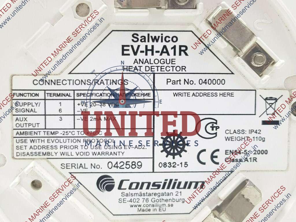
- Display/indicator failure due to electronics aging
- Sensor-Interface Kommunikationsfehler
- Software-/Firmware-Bugs erfordern Updates
- Antenna cable corrosion due to deck loading
- Voltage supply problems during electrical system fluctuations
- Unified multi‑sensor display reduces crew workload and improves situational awareness
- Modular sensor interfaces allow flexible integration of existing radar, AIS, GPS etc.
- Manufacturer provides regular software/firmware updates to address bugs and add features
- Designed for compliance with SOLAS bridge equipment inspection requirements
- Backup system test procedure included for monthly redundancy verification
- Display electronics can suffer age‑related failures requiring replacement
- Sensor interface communication errors have been reported in harsh sea conditions
- Software/firmware bugs may necessitate frequent updates and validation
- Antenna cabling is prone to corrosion when exposed to deck loads and moisture
- Voltage fluctuations on the ship’s power network can cause supply instability
- Display/indicator failure due to electronics aging
- Sensor-Interface Kommunikationsfehler
- Software-/Firmware-Bugs erfordern Updates
- Antenna cable corrosion due to deck loading
- Voltage supply problems during electrical system fluctuations
- Modular architecture allows easy addition of new sensors or displays
- Single‑screen situational awareness reduces crew workload
- Built‑in redundancy with backup system testable monthly
- Meets SOLAS bridge equipment inspection requirements
- Supports remote software updates via manufacturer advisory
- Display electronics can age, leading to occasional screen failures
- Sensor interface communication errors reported in field experience
- Frequent firmware patches required to resolve bugs
- Antenna cabling prone to corrosion when exposed to deck loads
- Sensitive to board‑network voltage fluctuations, requiring stable power supply
- Display/indicator failure due to electronics aging
- Sensor-Interface Kommunikationsfehler
- Software-/Firmware-Bugs erfordern Updates
- Antenna cable corrosion due to deck loading
- Voltage supply problems during electrical system fluctuations
- Provides a unified display of ECDIS, radar, AIS and other bridge sensors
- Modular architecture allows incremental upgrades and easy addition of new sensors
- Built‑in backup system test routine (monthly) supports SOLAS redundancy requirements
- Quarterly sensor calibration procedure is defined by the manufacturer
- Software can be updated via Consilium advisory to address bugs and regulatory changes
- Display electronics have shown age‑related failures, requiring periodic replacement
- Sensor interface communication errors reported under harsh electromagnetic environments
- Firmware bugs may necessitate frequent software patches
- Antenna cabling prone to corrosion when exposed to deck load stresses
- Power supply instability on vessels with fluctuating board voltage can cause outages
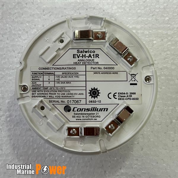
- Display/indicator failure due to electronics aging
- Sensor-Interface Kommunikationsfehler
- Software-/Firmware-Bugs erfordern Updates
- Antenna cable corrosion due to deck loading
- Voltage supply problems during electrical system fluctuations
- Full sensor fusion on one display reduces crew workload
- Modular architecture allows incremental upgrades of radar, AIS or ECDIS modules
- Built‑in redundancy with dual power feeds and hot‑standby processors
- Compliant with SOLAS bridge requirements and DNV approval for type‑approval
- Remote software/firmware update capability via manufacturer advisory
- Display electronics can degrade over time, leading to occasional screen failures
- Sensor interface communication errors have been reported in harsh vibration environments
- Software bugs may require frequent firmware patches to maintain stability
- Antenna and sensor cabling is prone to corrosion when exposed on deck loads
- Power‑fluctuation sensitivity can cause intermittent loss of function if shipboard voltage is not well regulated
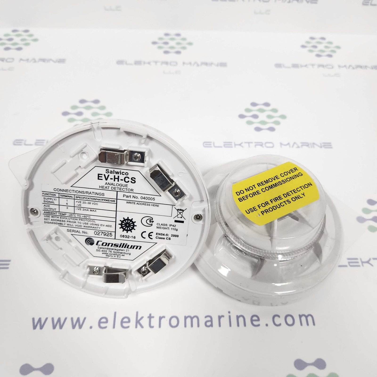
- Display/indicator failure due to electronics aging
- Sensor-Interface Kommunikationsfehler
- Software-/Firmware-Bugs erfordern Updates
- Antenna cable corrosion due to deck loading
- Voltage supply problems during electrical system fluctuations
- High level of sensor integration reduces cockpit clutter and improves situational awareness
- Modular architecture allows selective upgrade of individual sensors or display units
- Built‑in redundancy meets SOLAS requirements for critical navigation data
- Supports remote diagnostics and firmware updates via manufacturer advisory
- Designed for easy quarterly calibration of connected sensors
- Display failures reported due to electronic ageing, requiring periodic hardware refresh
- Sensor interface communication errors can arise if cabling is not regularly inspected
- Software/firmware bugs have necessitated frequent updates and operator training
- Antenna cable corrosion observed in high‑stress deck installations
- Power supply fluctuations on the ship’s electrical network may affect system stability
- Display/indicator failure due to electronics aging
- Sensor-Interface Kommunikationsfehler
- Software-/Firmware-Bugs erfordern Updates
- Antenna cable corrosion due to deck loading
- Voltage supply problems during electrical system fluctuations
- Modular architecture allows connection of multiple navigation sensors
- Built‑in backup system with monthly test capability enhances redundancy
- Software can be updated via manufacturer advisories to address bugs
- Meets SOLAS/Flag State inspection requirements with defined service intervals
- Provides a single pane‑of‑glass view, reducing crew workload
- Display units prone to failure as electronics age, requiring replacement
- Sensor interface communication errors have been reported in the field
- Frequent firmware/software updates needed to keep system stable
- Antenna cabling can corrode under deck load stresses if not inspected regularly
- Power supply fluctuations on board may cause intermittent operation

- Display/indicator failure due to electronics aging
- Sensor-Interface Kommunikationsfehler
- Software-/Firmware-Bugs erfordern Updates
- Antenna cable corrosion due to deck loading
- Voltage supply problems during electrical system fluctuations
- High level of sensor fusion reduces operator workload and improves safety
- Modular architecture allows easy addition of new sensors or software modules
- Built‑in redundancy with backup display tested monthly per SOLAS requirements
- DNV class approval simplifies flag‑state acceptance for newbuilds and retrofits
- Quarterly calibration procedures keep navigation data within required accuracy
- Display failures reported after prolonged exposure to marine humidity (electronics ageing)
- Corrosion of antenna cables can occur where deck fittings exert mechanical stress
- Software/firmware bugs occasionally require urgent patches from the manufacturer
- Sensitive to voltage fluctuations in the ship’s power network; may need auxiliary stabiliser
- Initial installation cost higher than stand‑alone ECDIS or radar units
- Display/indicator failure due to electronics aging
- Sensor-Interface Kommunikationsfehler
- Software-/Firmware-Bugs erfordern Updates
- Antenna cable corrosion due to deck loading
- Voltage supply problems during electrical system fluctuations
- Provides a unified display and control console, reducing crew workload on the bridge
- Modular architecture allows addition or replacement of sensor inputs (radar, AIS, GPS, etc.) without major rewiring
- Supports scheduled quarterly sensor calibration as recommended by the manufacturer
- Includes a built‑in backup system that can be tested monthly to verify redundancy
- Meets SOLAS/Flag State inspection requirements with annual service intervals
- Display electronics have shown age‑related failures, requiring replacement of display units over time
- Sensor interface communication errors have been reported, especially after cable wear or connector corrosion
- Software and firmware bugs may necessitate frequent updates from the manufacturer
- Antenna cables are prone to corrosion when subjected to deck load stresses
- Voltage fluctuations in the ship’s power network can cause intermittent supply problems
- Display/indicator failure due to electronics aging
- Sensor-Interface Kommunikationsfehler
- Software-/Firmware-Bugs erfordern Updates
- Antenna cable corrosion due to deck loading
- Voltage supply problems during electrical system fluctuations
- Unified multi‑sensor display reduces operator workload
- Modular sensor interfaces simplify upgrades and retrofits
- Meets SOLAS/Flag State inspection requirements with built‑in diagnostics
- Monthly backup‑system test ensures redundancy in case of primary failure
- Manufacturer issues regular software/firmware updates via advisory
- Display/display panel failures reported due to electronic ageing
- Sensor‑interface communication errors can interrupt data flow
- Software/firmware bugs may require frequent patching
- Antenna cable corrosion observed where deck loads stress the cabling
- Sensitivity to shipboard voltage fluctuations can cause power‑supply issues
- Display/indicator failure due to electronics aging
- Sensor-Interface Kommunikationsfehler
- Software-/Firmware-Bugs erfordern Updates
- Antenna cable corrosion due to deck loading
- Voltage supply problems during electrical system fluctuations
- Modular architecture allows easy addition or replacement of sensors and displays
- Single‑screen operator view reduces crew workload and improves decision speed
- Built‑in redundancy with backup display testing each month
- Quarterly sensor calibration keeps navigation data accurate
- Manufacturer provides regular software/firmware updates via advisory
- Electronic ageing can lead to display failures if not refreshed regularly
- Reported corrosion of antenna cables under deck load requires vigilant inspection
- Software bugs have required interim patches in past releases
- Sensitive to shipboard power fluctuations; voltage stabilisation may be needed
- Integration complexity can increase installation time on retrofit projects
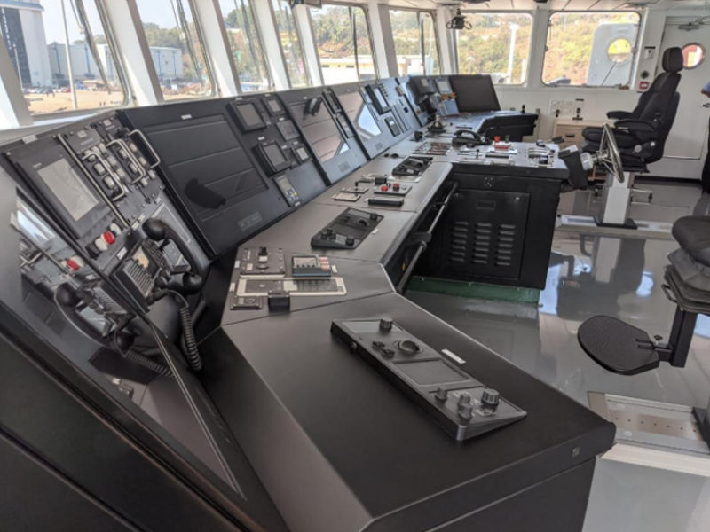
- Display/indicator failure due to electronics aging
- Sensor-Interface Kommunikationsfehler
- Software-/Firmware-Bugs erfordern Updates
- Antenna cable corrosion due to deck loading
- Voltage supply problems during electrical system fluctuations
- Unified multi‑sensor display reduces operator workload and improves situational awareness
- Modular architecture allows easy addition or replacement of radar, AIS, ECDIS and other sensors
- Redundant high‑resolution displays meet SOLAS bridge redundancy requirements
- Supports standard NMEA 0183/2000 interfaces for broad sensor compatibility
- Remote diagnostics and OTA software updates simplify maintenance
- Display/display panel failures reported due to electronic ageing
- Sensor‑interface communication errors can arise, requiring firmware patches
- Frequent software/firmware updates needed to address bugs
- Antenna cable corrosion observed when cables are subjected to deck load stresses
- Power supply disturbances on the ship’s electrical network may cause intermittent outages

- Display/indicator failure due to electronics aging
- Sensor-Interface Kommunikationsfehler
- Software-/Firmware-Bugs erfordern Updates
- Antenna cable corrosion due to deck loading
- Voltage supply problems during electrical system fluctuations
- Integrated multi‑sensor display reduces operator workload
- Modular hardware allows easy addition or replacement of sensors
- DNV approved, meeting major classification requirements
- Manufacturer provides regular software/firmware updates
- Redundant power inputs mitigate short‑term voltage drops
- Display electronics can fail with age, requiring costly replacements
- Reported sensor‑interface communication errors under certain conditions
- Frequent firmware updates needed to address bugs
- Antenna cable corrosion observed in high‑stress deck installations
- Sensitive to shipboard power fluctuations if not properly filtered
- Display/indicator failure due to electronics aging
- Sensor-Interface Kommunikationsfehler
- Software-/Firmware-Bugs erfordern Updates
- Antenna cable corrosion due to deck loading
- Voltage supply problems during electrical system fluctuations
- High level of sensor fusion reduces operator workload and improves situational awareness.
- Modular design (A2, A2‑IS, IP67 variants) allows selection of additional interfaces and ruggedisation for harsh environments.
- Built‑in redundancy with backup display testing capability enhances safety compliance with SOLAS.
- Quarterly sensor calibration procedures are supported by the system’s self‑diagnostic tools.
- Software can be updated remotely via manufacturer advisories, keeping the system current with regulatory changes.
- Display failures have been reported as equipment ages, requiring proactive replacement planning.
- Sensor interface communication errors may arise if cabling is not protected against deck‑load corrosion.
- Firmware bugs occasionally necessitate unscheduled downtime for updates.
- Power supply fluctuations on the vessel’s electrical network can cause intermittent system instability.
- Initial capital cost and integration effort are higher than stand‑alone navigation units.
- Display/indicator failure due to electronics aging
- Sensor-Interface Kommunikationsfehler
- Software-/Firmware-Bugs erfordern Updates
- Antenna cable corrosion due to deck loading
- Voltage supply problems during electrical system fluctuations
- Modular plug‑in design simplifies installation and future upgrades
- Built‑in short‑circuit isolation protects bridge electronics from wiring failures
- Integrated diagnostics can be accessed via the manufacturer’s software for rapid troubleshooting
- Supports a wide range of sensor interfaces (NMEA, analog, digital) in one unit
- Designed to meet SOLAS/Flag State inspection requirements
- Firmware updates are required regularly to address known bugs
- Antenna cables can corrode under deck load and harsh marine conditions
- Sensitive to board voltage fluctuations; may need auxiliary power conditioning
- Higher upfront cost compared with basic I/O boards lacking fault isolation
- Configuration complexity may be excessive for small vessels with limited bridge systems
- Display/indicator failure due to electronics aging
- Sensor-Interface Kommunikationsfehler
- Software-/Firmware-Bugs erfordern Updates
- Antenna cable corrosion due to deck loading
- Voltage supply problems during electrical system fluctuations
- Open, NMEA‑compatible architecture allows easy integration of legacy and new sensors
- Redundant hardware modules provide SOLAS‑compliant fail‑safe operation
- Scalable display configuration – supports multiple ECDIS/AIS/radar screens
- Remote diagnostics and firmware management via manufacturer advisory service
- Certified to IMO Integrated Bridge System (IBS) requirements, facilitating class approval
- Electronic displays can suffer age‑related failures; periodic replacement may be required
- Sensor interface communication errors have been reported, necessitating careful wiring checks
- Software/firmware bugs occasionally demand urgent updates to maintain compliance
- Antenna cabling is prone to corrosion when exposed to deck loads and harsh marine environments
- Power‑supply fluctuations on the ship’s bus can cause intermittent system instability
- Display/indicator failure due to electronics aging
- Sensor-Interface Kommunikationsfehler
- Software-/Firmware-Bugs erfordern Updates
- Antenna cable corrosion due to deck loading
- Voltage supply problems during electrical system fluctuations
- Intrinsic safety (Ex ic) rating suitable for gas‑filled or explosive atmospheres
- Integrated sensor fusion reduces crew workload and improves situational awareness
- Modular architecture allows easy addition of new sensors or displays
- Meets SOLAS/Flag State inspection requirements with built‑in self‑test routines
- Supported by DNV approval, ensuring compliance with classification society standards
- Display units prone to failure as electronics age, requiring periodic replacement
- Sensor interface communication errors reported in field service bulletins
- Frequent software/firmware updates needed to address bugs and maintain certification
- Antenna cable corrosion observed when exposed to deck‑load stresses
- Power supply sensitivity to board voltage fluctuations can cause intermittent outages
- Display/indicator failure due to electronics aging
- Sensor-Interface Kommunikationsfehler
- Software-/Firmware-Bugs erfordern Updates
- Antenna cable corrosion due to deck loading
- Voltage supply problems during electrical system fluctuations
- High level of integration reduces cabling and operator workload
- Modular design allows phased upgrades and easy replacement of faulty modules
- Redundant display units meet SOLAS redundancy requirements
- Supports NMEA 0183/2000 sensor interfaces for most commercial navigation equipment
- Manufacturer provides remote diagnostics and regular software advisories
- Display electronics can age, leading to occasional screen failures (known issue)
- Antenna and sensor cabling prone to corrosion when exposed to deck loads
- Software/firmware bugs require frequent updates; downtime possible during patching
- Power‑supply sensitivity may cause instability on vessels with fluctuating board voltage
- Higher upfront cost compared with basic stand‑alone radar/ECDIS units

- Display/indicator failure due to electronics aging
- Sensor-Interface Kommunikationsfehler
- Software-/Firmware-Bugs erfordern Updates
- Antenna cable corrosion due to deck loading
- Voltage supply problems during electrical system fluctuations
- Modular panels allow phased upgrades or selective replacement
- IP67 and Ex‑rated variants protect against water ingress and hazardous atmospheres
- DNV class approval ensures compliance with SOLAS and bridge safety standards
- Integrated software platform supports remote diagnostics and over‑the‑air updates
- Built‑in redundancy (dual power feeds, backup display) enhances reliability
- Display units can suffer age‑related failure; replacement parts may be costly
- Sensor interface communication errors have been reported in harsh vibration environments
- Antennacable corrosion is a known issue on decks with high mechanical load
- Power supply fluctuations can cause intermittent outages if not properly filtered
- Software/firmware bugs require regular manufacturer advisories and testing
- Display/indicator failure due to electronics aging
- Sensor-Interface Kommunikationsfehler
- Software-/Firmware-Bugs erfordern Updates
- Antenna cable corrosion due to deck loading
- Voltage supply problems during electrical system fluctuations
- Consolidates multiple navigation sensors onto one screen, reducing operator workload
- Modular architecture allows easy addition or replacement of sensor interfaces
- Meets SOLAS bridge inspection requirements with defined annual and monthly test procedures
- Manufacturer provides regular software advisories to address firmware bugs
- Quarterly sensor calibration maintains data accuracy
- Display electronics have a documented aging‑related failure mode
- Sensor interface communication errors reported in service history
- Software/firmware bugs require frequent updates
- Antenna cabling can corrode under deck load conditions
- Sensitive to board power fluctuations, leading to occasional voltage‑supply issues
- Display/indicator failure due to electronics aging
- Sensor-Interface Kommunikationsfehler
- Software-/Firmware-Bugs erfordern Updates
- Antenna cable corrosion due to deck loading
- Voltage supply problems during electrical system fluctuations
- Unified display reduces operator workload and improves situational awareness
- Modular sensor interfaces allow flexible configuration for different vessel setups
- Supports remote software/firmware updates via manufacturer advisories
- Designed to meet SOLAS and flag‑state inspection requirements
- Includes a backup system that can be tested monthly
- Display/display panel failures reported due to electronic ageing
- Sensor‑interface communication errors can occur if connectors degrade
- Software/firmware bugs may require frequent updates
- Antenna cable corrosion observed when cables are exposed to deck loads
- Power supply instability on vessels with fluctuating board voltage can affect operation
- Display/indicator failure due to electronics aging
- Sensor-Interface Kommunikationsfehler
- Software-/Firmware-Bugs erfordern Updates
- Antenna cable corrosion due to deck loading
- Voltage supply problems during electrical system fluctuations
- Modular architecture allows easy addition of new sensors or displays
- Built‑in redundancy (backup display & power monitoring) meets SOLAS requirements
- Supports automatic software/firmware updates via manufacturer advisories
- Quarterly sensor calibration procedures are defined in the service manual
- Designed for harsh marine environments with sealed enclosures
- Display units can suffer from electronic ageing leading to occasional blank screens
- Sensor‑interface communication errors have been reported under high electromagnetic interference
- Software bugs occasionally require emergency patches, increasing downtime risk
- Antenna cables are prone to corrosion when exposed to deck load stresses
- Power supply fluctuations on the ship’s bus can cause intermittent system resets
- Display/indicator failure due to electronics aging
- Sensor-Interface Kommunikationsfehler
- Software-/Firmware-Bugs erfordern Updates
- Antenna cable corrosion due to deck loading
- Voltage supply problems during electrical system fluctuations
- Modular architecture allows easy addition of new sensor inputs
- Built‑in redundancy with dual display units for higher availability
- Supports standard maritime data protocols (NMEA 0183/2000, IEC 61162)
- Software can be updated remotely via manufacturer advisories
- Designed to meet SOLAS bridge equipment inspection intervals
- Display modules prone to failure as electronics age
- Sensor‑interface communication errors reported in field service logs
- Frequent firmware patches required to resolve bugs
- Antenna cabling susceptible to corrosion from deck loading and marine environment
- Power supply stability issues when shipboard voltage fluctuates
- Display/indicator failure due to electronics aging
- Sensor-Interface Kommunikationsfehler
- Software-/Firmware-Bugs erfordern Updates
- Antenna cable corrosion due to deck loading
- Voltage supply problems during electrical system fluctuations
- Modular hardware (Base, Addr Base, Rugged Addr Base) allows tailoring to vessel layout and environmental demands
- DNV‑approved integration ensures compliance with major classification society standards
- Centralised display reduces crew workload and improves situational awareness
- Supports a wide range of sensor interfaces and can be expanded with additional modules
- Display units prone to ageing‑related failures, requiring periodic replacement
- Sensor‑interface communication errors reported in field experience
- Software/firmware bugs necessitate regular manufacturer advisories and updates
- Antenna cable corrosion observed when exposed to deck load stresses
- Power‑supply sensitivity to board‑network voltage fluctuations
- Display/indicator failure due to electronics aging
- Sensor-Interface Kommunikationsfehler
- Software-/Firmware-Bugs erfordern Updates
- Antenna cable corrosion due to deck loading
- Voltage supply problems during electrical system fluctuations
- Unified display reduces crew workload and improves situational awareness
- Supports multiple standard sensors (radar, AIS, GPS, etc.) through common interfaces
- DNV‑approved design gives recognised class society acceptance
- Manufacturer‑provided software/firmware updates via advisory service
- Monthly backup‑system test built into the maintenance regime
- Display failures reported due to electronic ageing
- Sensor‑interface communication errors can occur if wiring degrades
- Frequent firmware patches required to address bugs
- Antenna cable corrosion observed when deck loads are high
- Sensitivity to board‑network voltage fluctuations may cause power issues
- Display/indicator failure due to electronics aging
- Sensor-Interface Kommunikationsfehler
- Software-/Firmware-Bugs erfordern Updates
- Antenna cable corrosion due to deck loading
- Voltage supply problems during electrical system fluctuations
- High integration reduces cabling, deck space and installation time
- Modular product line (FP10, IC10, TC10) allows scaling to vessel size and budget
- Built‑in redundancy (dual processors/displays) satisfies SOLAS bridge‑watch requirements
- Broad native support for radar, AIS, GPS, gyrocompass, depth sounder and other common sensors
- Remote diagnostics and OTA software updates simplify lifecycle management
- Display/electronic ageing can cause screen failures if not refreshed regularly
- Antenna‑cable corrosion reported when cables are routed under deck loads without proper protection
- Software/firmware bugs have required frequent patch cycles in the field
- Sensitive to shipboard voltage fluctuations; may need additional power conditioning or UPS
- Third‑party sensor compatibility can be limited compared with larger IBS vendors
- Display/indicator failure due to electronics aging
- Sensor-Interface Kommunikationsfehler
- Software-/Firmware-Bugs erfordern Updates
- Antenna cable corrosion due to deck loading
- Voltage supply problems during electrical system fluctuations
- Modular architecture allows easy addition or replacement of sensors and displays
- Provides redundant data paths to meet SOLAS bridge redundancy requirements
- Supports a wide range of third‑party navigation equipment (ECDIS, AIS, radar, gyrocompass, etc.)
- Remote diagnostics and firmware update capability via manufacturer advisory
- Designed for compliance with annual SOLAS/Flag State inspections
- Display electronics can suffer age‑related failures if not refreshed regularly
- Sensor interface communication errors have been reported in harsh vibration environments
- Software/firmware bugs may require frequent updates to maintain stability
- Antenna cabling is prone to corrosion when exposed to deck load stresses
- Power supply fluctuations on the ship’s network can cause intermittent outages
- Display/indicator failure due to electronics aging
- Sensor-Interface Kommunikationsfehler
- Software-/Firmware-Bugs erfordern Updates
- Antenna cable corrosion due to deck loading
- Voltage supply problems during electrical system fluctuations
- Modular architecture allows easy addition or replacement of sensor inputs
- Integrated display reduces cockpit clutter and improves operator ergonomics
- Built‑in redundancy with backup system test capability per SOLAS requirements
- Quarterly sensor calibration procedures are defined by the manufacturer
- Software can be updated remotely via Consilium advisory notices
- Older electronic components may suffer display failures as noted in field reports
- Sensor interface communication errors have been reported, requiring firmware patches
- Antennacable corrosion risk when deck loads are high; requires regular inspection
- Power supply stability is critical – voltage fluctuations can cause system resets
- Software/firmware bugs occasionally necessitate unscheduled downtime for updates
Danelec Marine
13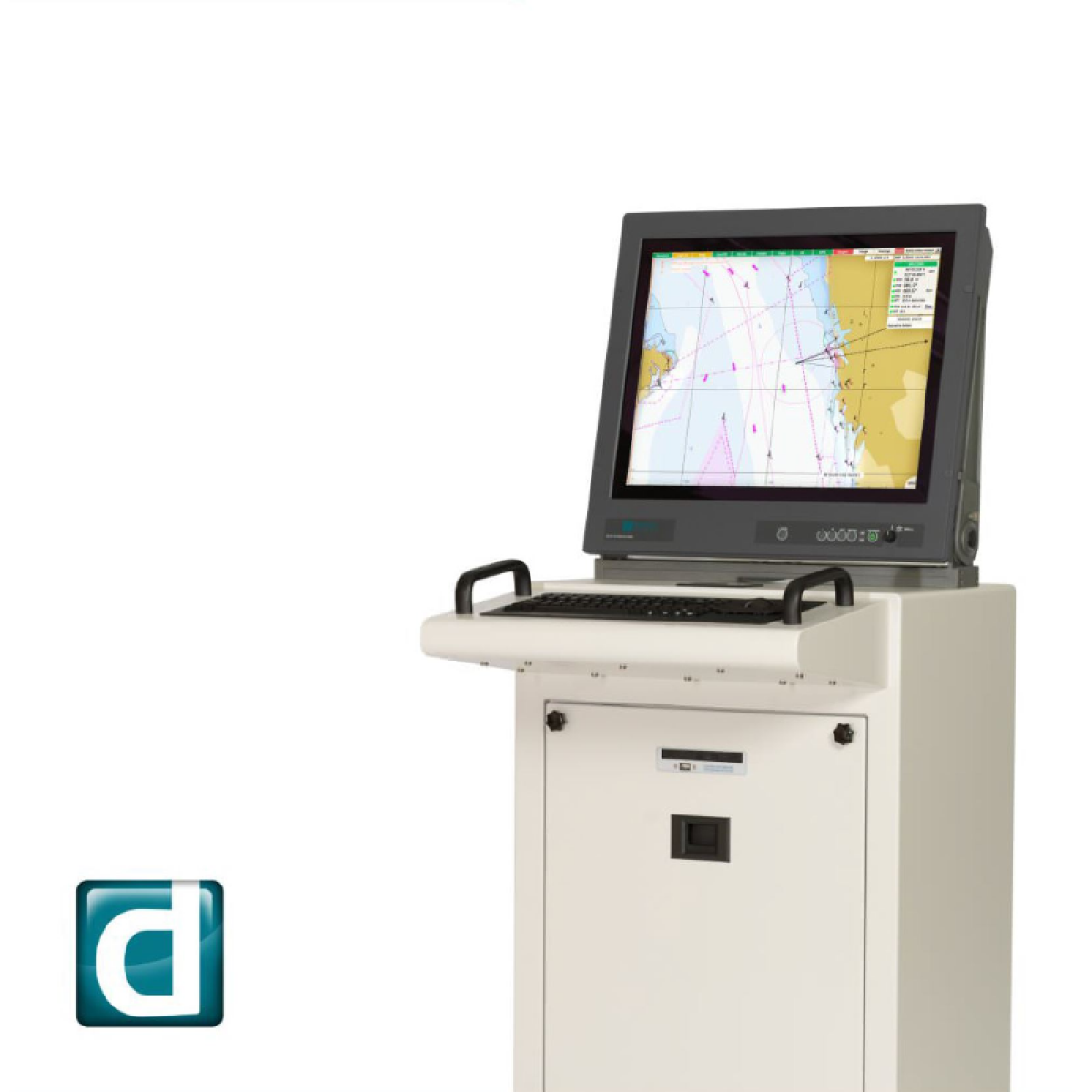
- Sensor, antenna or transducer fouling, damage or misalignment causes unstable, missing or inaccurate data
- Power-supply or processor faults cause resets, blank displays or complete loss of indication
- Cable, connector or network faults cause intermittent data or loss of outputs to dependent bridge systems
- Incorrect configuration or calibration causes persistent disagreement with independent references
- Display, storage or software faults cause frozen values, alarms or unavailable navigation functions
- Large 24‑inch high‑resolution display improves situational awareness
- Full compliance with IMO ECDIS performance standards (IMO approved)
- Supports both S‑57 and encrypted S‑63 ENC formats for global chart coverage
- Seamless integration with other Danelec bridge equipment such as VDRs
- User interface designed for quick chart manipulation and route planning
- Reported fan failures in high‑humidity environments can lead to overheating
- Occasional rendering delays or errors when navigating dense archipelagic waters
- USB ports have shown reliability issues, affecting peripheral connections
- Being a newer product line, long‑term field data and fleet experience are limited
- Sensor, antenna or transducer fouling, damage or misalignment causes unstable, missing or inaccurate data
- Power-supply or processor faults cause resets, blank displays or complete loss of indication
- Cable, connector or network faults cause intermittent data or loss of outputs to dependent bridge systems
- Incorrect configuration or calibration causes persistent disagreement with independent references
- Display, storage or software faults cause frozen values, alarms or unavailable navigation functions
- IMO‑approved full VDR meeting SOLAS requirements
- Long 30‑day solid‑state recording capacity
- Comprehensive bridge integration reduces cabling and simplifies installation
- User‑friendly playback software with reliable data extraction tools
- Modular design allows future sensor upgrades
- Reported capsule release mechanism failures can hinder post‑incident data retrieval
- Data acquisition unit fan failures may cause overheating if not serviced promptly
- Occasional sensor input dropout leading to short gaps in recorded data
- Annual functional test required, adding maintenance workload
- Higher upfront cost compared with basic stand‑alone VDRs
- Sensor, antenna or transducer fouling, damage or misalignment causes unstable, missing or inaccurate data
- Power-supply or processor faults cause resets, blank displays or complete loss of indication
- Cable, connector or network faults cause intermittent data or loss of outputs to dependent bridge systems
- Incorrect configuration or calibration causes persistent disagreement with independent references
- Display, storage or software faults cause frozen values, alarms or unavailable navigation functions
- Cost‑effective solution compared with full‑scale VDRs
- Integrated bridge display simplifies installation and operation
- IMO‑approved 30‑day recording meets SOLAS requirements
- Strong after‑sales service network across Europe
- Compact package suitable for retrofits on existing bridges
- Limited number of input channels restricts sensor connectivity
- Reported data‑storage reliability issues in long‑term use
- Capsule (recording unit) requires periodic maintenance and replacement
- Lower redundancy than high‑end VDR systems
- May lack advanced analytics or remote monitoring features
- Sensor, antenna or transducer fouling, damage or misalignment causes unstable, missing or inaccurate data
- Power-supply or processor faults cause resets, blank displays or complete loss of indication
- Cable, connector or network faults cause intermittent data or loss of outputs to dependent bridge systems
- Incorrect configuration or calibration causes persistent disagreement with independent references
- Display, storage or software faults cause frozen values, alarms or unavailable navigation functions
- Three‑stage monitoring provides graduated alarms for increased safety
- Fully integrated with Danelec DM100/DM200 VDR packages for streamlined installation
- IMO SOLAS approved, ensuring regulatory compliance on international voyages
- Compact bridge‑mounted design compatible with existing Danelec consoles
- Proven track record in new builds and retrofits across multiple vessel classes
- Sensor positioning can be sensitive; improper mounting may cause false alarms
- Timer configuration settings are complex and may require specialist programming
- Reported occasional alarm relay reliability issues under harsh vibration environments
- Limited interoperability with non‑Danelec bridge or alarm systems
- Service documentation often bundled with VDR, making standalone support less accessible
- Display/indicator failure due to electronics aging
- Sensor-Interface Kommunikationsfehler
- Software-/Firmware-Bugs erfordern Updates
- Antenna cable corrosion due to deck loading
- Voltage supply problems during electrical system fluctuations
- Full SOLAS‑compliant VDR functionality integrated on the bridge, eliminating separate recorder hardware
- Modular architecture allows phased upgrades of displays, radar and ECDIS without full system replacement
- Class approvals (DNV, ABS, LR) and IMO SOLAS certification simplify flag‑state acceptance
- Redundant power and data paths increase reliability for critical navigation functions
- Vendor provides regular software/firmware updates and a structured maintenance plan
- High initial capital cost compared with stand‑alone ECDIS or radar solutions
- Complex system integration requires specialised installation and training crew
- Display units are known to suffer age‑related electronic failures, requiring periodic replacement
- Antenna cable routing on deck can be prone to corrosion if not inspected regularly
- Sensitive to shipboard power fluctuations; voltage conditioning may be needed
- Display/indicator failure due to electronics aging
- Sensor-Interface Kommunikationsfehler
- Software-/Firmware-Bugs erfordern Updates
- Antenna cable corrosion due to deck loading
- Voltage supply problems during electrical system fluctuations
- Full SOLAS compliance with automatic event marking and tamper‑evident storage
- Modular sensor interface allowing easy connection to existing radar, AIS, GPS, gyrocompass and bridge audio systems
- Redundant power input and internal battery backup ensures continuous recording during voltage fluctuations
- Remote diagnostics and firmware update capability via manufacturer advisory portal
- Scalable storage (up to 2 TB) supports high‑resolution video from multiple cameras
- Display unit failures reported after prolonged exposure to marine humidity (electronic ageing)
- Sensor interface communication errors can arise if cable routing is not protected against deck‑load corrosion
- Software/firmware bugs occasionally require unscheduled downtime for patches
- Power supply sensitivity; sharp fluctuations in the ship’s electrical network may trigger recording interruptions
- Monthly backup‑system testing adds operational overhead
- Display/indicator failure due to electronics aging
- Sensor-Interface Kommunikationsfehler
- Software-/Firmware-Bugs erfordern Updates
- Antenna cable corrosion due to deck loading
- Voltage supply problems during electrical system fluctuations
- Full compliance with IMO SOLAS Chapter V regulation for Voyage Data Recorders
- DNV class approval and proven track record on newbuilds and retrofits
- Modular design allows hot‑swap of storage units and easy expansion
- Remote diagnostics and firmware updates via manufacturer advisory service
- Built‑in redundancy with dual recording paths to protect data integrity
- Display/display unit failures reported due to electronic ageing (requires periodic replacement)
- Sensor interface communication errors can arise if cabling is not inspected regularly
- Antennacable corrosion observed in harsh deck environments, increasing maintenance effort
- Frequent software/firmware updates needed to address bugs and maintain certification
- Power‑supply sensitivity to shipboard voltage fluctuations may cause occasional resets
- Display/indicator failure due to electronics aging
- Sensor-Interface Kommunikationsfehler
- Software-/Firmware-Bugs erfordern Updates
- Antenna cable corrosion due to deck loading
- Voltage supply problems during electrical system fluctuations
- Dual‑redundant recording architecture satisfies the most stringent SOLAS criteria
- Integrated bridge interface (IBS/INS) allows seamless data capture from all major navigation sensors
- High‑capacity solid‑state storage enables multi‑day retention and fast playback for investigations
- Modular hardware design supports easy upgrades and field service without extensive downtime
- Remote diagnostics and firmware update capability via manufacturer advisory
- Display units can suffer from age‑related electronic failure, requiring periodic replacement
- Sensor‑interface communication errors have been reported when legacy equipment is connected
- Firmware bugs occasionally necessitate urgent software patches to maintain compliance
- Antenna and cabling on the deck are prone to corrosion under harsh marine exposure
- Power quality fluctuations on older vessels can cause intermittent recorder shutdowns
- Display/indicator failure due to electronics aging
- Sensor-Interface Kommunikationsfehler
- Software-/Firmware-Bugs erfordern Updates
- Antenna cable corrosion due to deck loading
- Voltage supply problems during electrical system fluctuations
- Full SOLAS‑compliant recording of bridge audio, video, radar, AIS, ECDIS and other sensors in a single modular unit
- Redundant storage architecture (dual hard‑disk mirroring) for high data integrity
- Scalable architecture – can be expanded with additional sensor modules or upgraded to G2/G3 generations without full system replacement
- Remote diagnostics and firmware update capability via manufacturer advisory service
- Integrated backup test function that can be scheduled monthly
- Higher upfront cost compared with stand‑alone VDRs, making it less attractive for small vessels
- Complex installation requiring extensive cabling and deck penetration; potential for antenna‑cable corrosion if not protected
- Software/firmware bugs have been reported that necessitate frequent updates and careful change‑management procedures
- Power quality sensitivity – voltage fluctuations on the ship’s bus can cause occasional supply issues
- Quarterly sensor calibration adds to maintenance workload
- Display/indicator failure due to electronics aging
- Sensor-Interface Kommunikationsfehler
- Software-/Firmware-Bugs erfordern Updates
- Antenna cable corrosion due to deck loading
- Voltage supply problems during electrical system fluctuations
- Reduces cabling and wiring complexity by fusing multiple sensor inputs
- Modular architecture allows easy addition of new sensors or displays
- Supports standard maritime data protocols (NMEA 0183/2000, IEC 61162)
- Provides a single‑screen situational awareness view for the officer on watch
- Manufacturer offers regular software updates and remote diagnostics
- Older electronic components can lead to display failures over time
- Sensor interface communication errors reported in harsh marine environments
- Requires frequent firmware patches to resolve bugs
- Antennacable corrosion observed when deck loads are high
- Sensitive to board‑network voltage fluctuations, necessitating stable power conditioning
- Display/indicator failure due to electronics aging
- Sensor-Interface Kommunikationsfehler
- Software-/Firmware-Bugs erfordern Updates
- Antenna cable corrosion due to deck loading
- Voltage supply problems during electrical system fluctuations
- Fully solid‑state storage eliminates moving parts and improves reliability under harsh marine conditions
- Integrated bridge system (IBS/INS) interface supports a wide range of sensor manufacturers, simplifying installation on modern ships
- Meets IMO SOLAS VDR requirements with built‑in redundancy and automatic backup recording
- Modular design allows easy firmware upgrades and replacement of individual components without full system shutdown
- Compliant with DNV class approval, facilitating acceptance by major flag states
- Higher upfront cost compared with legacy tape‑based VDRs
- Complex sensor interface can require additional configuration effort on vessels with non‑standard equipment
- Firmware updates must be managed carefully to avoid compatibility issues with existing bridge software
- Physical installation may demand reinforced mounting due to the unit’s size and weight
- Backup‑system testing is mandatory monthly, adding to crew workload
- Display/indicator failure due to electronics aging
- Sensor-Interface Kommunikationsfehler
- Software-/Firmware-Bugs erfordern Updates
- Antenna cable corrosion due to deck loading
- Voltage supply problems during electrical system fluctuations
- Full SOLAS‑compliant data capture (position, radar, AIS, ECDIS, VHF, engine sensors, etc.) in a single integrated unit
- Modular design allows easy expansion with additional sensor interfaces
- Built‑in dual‑redundant storage and automatic backup testing to meet IMO reliability requirements
- Remote firmware update capability via manufacturer advisory reduces on‑site downtime
- Compact bridge‑mountable form factor simplifies installation on new builds and retrofits
- Electronic component ageing can lead to display failures if not refreshed regularly
- Corrosion of antenna cabling is reported in high‑humidity deck environments
- Software bugs have required periodic firmware patches; older versions may be vulnerable
- Sensitive to severe voltage fluctuations on the ship’s power bus, necessitating stable UPS protection
- Initial cost and integration effort are higher than basic stand‑alone VDRs
- Display/indicator failure due to electronics aging
- Sensor-Interface Kommunikationsfehler
- Software-/Firmware-Bugs erfordern Updates
- Antenna cable corrosion due to deck loading
- Voltage supply problems during electrical system fluctuations
- Unified multi‑sensor display reduces operator workload
- Modular architecture allows easy addition of new sensors or upgrades
- DNV‑approved design provides recognised class compliance
- Built‑in redundancy with backup system testing capability
- Supports remote firmware and software updates from manufacturer
- Display electronics can age, leading to occasional screen failures
- Sensor interface communication errors reported in harsh environments
- Frequent software/firmware updates required to fix bugs
- Antenna cabling prone to corrosion when exposed to deck loads
- Sensitive to board‑network voltage fluctuations, requiring stable power supply
Wärtsilä
2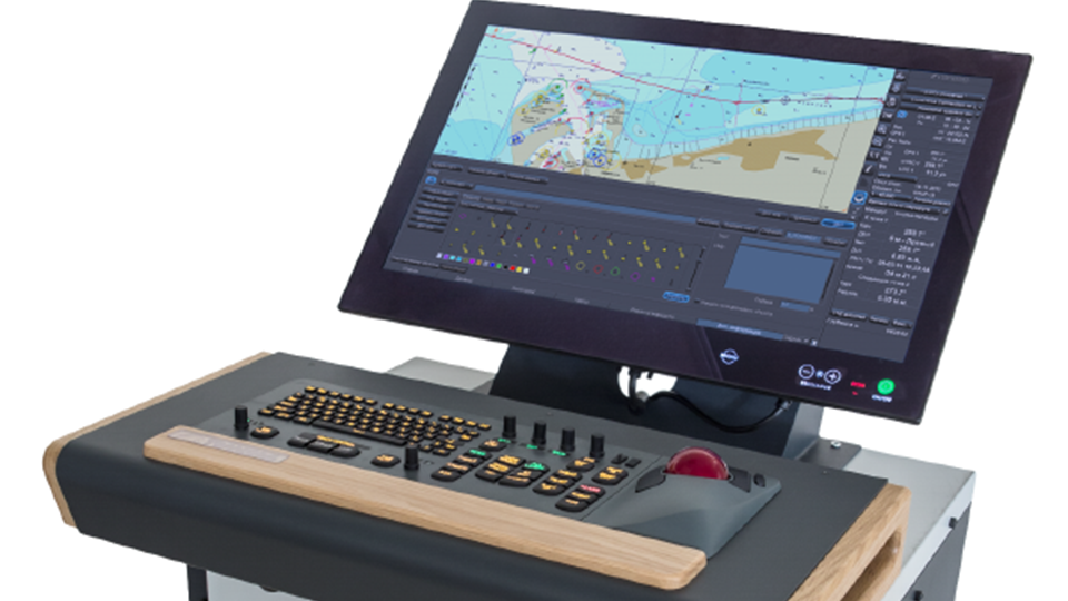
- Sensor, antenna or transducer fouling, damage or misalignment causes unstable, missing or inaccurate data
- Power-supply or processor faults cause resets, blank displays or complete loss of indication
- Cable, connector or network faults cause intermittent data or loss of outputs to dependent bridge systems
- Incorrect configuration or calibration causes persistent disagreement with independent references
- Display, storage or software faults cause frozen values, alarms or unavailable navigation functions
- Fully integrated suite (ECDIS, radar, AIS, autopilot) reduces cockpit clutter
- IMO Performance Standard approved and USCG type‑approved for ECDIS functionality
- Modular architecture allows easy addition of new sensors or upgrades
- Strong global support network through Wärtsilä’s service organisation
- Proven on a wide range of large commercial vessels
- Software licensing fees are recurring and can be high for full‑feature packs
- Post‑acquisition transition to Wärtsilä has caused occasional support delays
- Complex integration may require specialised installers and longer commissioning times
- Updates sometimes introduce compatibility issues with legacy sensor hardware
- Less open than some competitors, limiting third‑party customisation
- Sensor, antenna or transducer fouling, damage or misalignment causes unstable, missing or inaccurate data
- Power-supply or processor faults cause resets, blank displays or complete loss of indication
- Cable, connector or network faults cause intermittent data or loss of outputs to dependent bridge systems
- Incorrect configuration or calibration causes persistent disagreement with independent references
- Display, storage or software faults cause frozen values, alarms or unavailable navigation functions
- Highly modular architecture allowing easy addition of new sensors and subsystems
- Unified user interface reduces operator workload and improves situational awareness
- Built‑in redundancy and fault‑tolerant design meet IMO bridge system requirements
- Supports a wide range of third‑party equipment through open interfaces (NMEA 2000, IEC 61162)
- Remote diagnostics and software update capability from shore
- Complex multi‑vendor sensor integration can require extensive engineering effort
- Software version management is critical; mismatched releases may cause interoperability issues
- Steeper training curve for bridge crew compared with simpler stand‑alone displays
- Initial capital cost higher than basic single‑vendor ECDIS solutions
- Dependence on proprietary Wärtsilä support for certain advanced functions
Alphatron Marine
1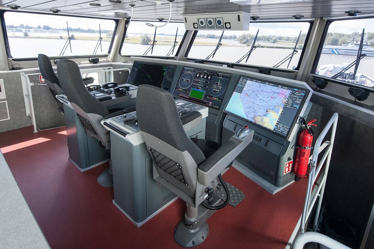
- Sensor, antenna or transducer fouling, damage or misalignment causes unstable, missing or inaccurate data
- Power-supply or processor faults cause resets, blank displays or complete loss of indication
- Cable, connector or network faults cause intermittent data or loss of outputs to dependent bridge systems
- Incorrect configuration or calibration causes persistent disagreement with independent references
- Display, storage or software faults cause frozen values, alarms or unavailable navigation functions
- Low acquisition cost compared with major OEM IBS solutions
- Highly modular – additional displays or functions can be added as the vessel grows
- Open architecture allows easy integration of third‑party navigation equipment
- Touch‑screen UI is intuitive and reduces crew training time
- Relatively low power consumption, suitable for vessels with limited electrical capacity
- Limited global service network; support may be slower on remote routes
- Spare parts and component sourcing can experience long lead times
- Software stability reported as less robust under heavy data loads or frequent updates
- Fewer advanced redundancy features than high‑end competitors (e.g., Wärtsilä, Kongsberg)
- Limited class approvals; may not meet strict certification requirements for large tankers
Anschütz
1Böning
1
- Sensor, antenna or transducer fouling, damage or misalignment causes unstable, missing or inaccurate data
- Power-supply or processor faults cause resets, blank displays or complete loss of indication
- Cable, connector or network faults cause intermittent data or loss of outputs to dependent bridge systems
- Incorrect configuration or calibration causes persistent disagreement with independent references
- Display, storage or software faults cause frozen values, alarms or unavailable navigation functions
- Modular multi‑function displays ranging from 15" to 55" for flexible bridge layouts
- High‑resolution, marine‑grade LCD panels with built‑in anti‑glare coating
- Native support for ECDIS, radar overlay, AIS and engine monitoring in a single UI
- Ergonomic design with adjustable tilt and easy‑access touch controls
- Widely installed on passenger and offshore vessels, giving proven reliability
- Backlight lifespan can be limited (typically ~20 000 h) requiring periodic replacement
- Touch panel may drift over time and need recalibration in harsh marine environments
- Reported EMC compliance issues that sometimes demand extra shielding or grounding measures
- Higher upfront cost compared with basic single‑function displays
- Integration with some third‑party software platforms can be less open than fully modular IBS solutions
Consilium Marine
1
- Sensor, antenna or transducer fouling, damage or misalignment causes unstable, missing or inaccurate data
- Power-supply or processor faults cause resets, blank displays or complete loss of indication
- Cable, connector or network faults cause intermittent data or loss of outputs to dependent bridge systems
- Incorrect configuration or calibration causes persistent disagreement with independent references
- Display, storage or software faults cause frozen values, alarms or unavailable navigation functions
- Combines fire, navaid and engine alarms on one panel, reducing bridge clutter
- Configurable alarm groups and priority settings allow tailoring to vessel operations
- Modular construction simplifies installation and future upgrades
- Standard audible/visual alerts with acknowledgment button improve crew response time
- Compact footprint suitable for vessels with limited bridge space
- Relay contacts have a documented wear pattern, requiring regular inspection or replacement
- LED indicator modules have been reported to fail prematurely in some units
- Alarm acknowledgment button can degrade under heavy use, leading to missed acknowledgments
- Limited publicly available certification data compared with larger OEMs
- Support network may be smaller than that of major bridge equipment manufacturers
Furuno
1- Sensor, antenna or transducer fouling, damage or misalignment causes unstable, missing or inaccurate data
- Power-supply or processor faults cause resets, blank displays or complete loss of indication
- Cable, connector or network faults cause intermittent data or loss of outputs to dependent bridge systems
- Incorrect configuration or calibration causes persistent disagreement with independent references
- Display, storage or software faults cause frozen values, alarms or unavailable navigation functions
- Single unified display reduces operator workload and improves situational awareness
- Seamless radar/ECDIS overlay eliminates manual chart updates
- IMO approved integration meets SOLAS requirements for bridge equipment
- Modular architecture allows easy addition of AIS, GNSS, or other sensors
- Reduced cabling and hardware footprint compared with separate stand‑alone units
- Heavy reliance on the ship’s network backbone; a single point of failure can affect all displays
- Occasional sensor polling errors reported in high‑traffic environments
- Chart/radar overlay misalignment may require frequent calibration
- Higher upfront cost than basic stand‑alone radar or ECDIS units
- Installation and software configuration are more complex, requiring specialised support
Hatteland Technology
1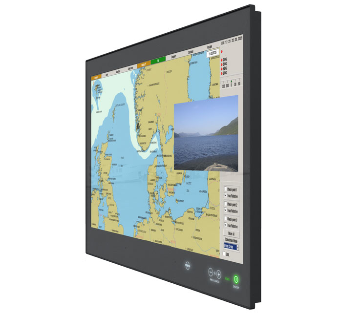
- Sensor, antenna or transducer fouling, damage or misalignment causes unstable, missing or inaccurate data
- Power-supply or processor faults cause resets, blank displays or complete loss of indication
- Cable, connector or network faults cause intermittent data or loss of outputs to dependent bridge systems
- Incorrect configuration or calibration causes persistent disagreement with independent references
- Display, storage or software faults cause frozen values, alarms or unavailable navigation functions
- Designed as a drop‑in display for most IBS/INS vendors, simplifying integration
- High‑resolution graphics suitable for ECDIS and radar overlay
- Compact, low‑profile unit reduces bridge clutter
- CE marked and IEC 60945 compliant, meeting marine navigation standards
- Fanless cooling can overheat in tropical or high‑ambient temperatures
- LCD panel aging may lead to reduced brightness/contrast after several years
- BIOS backup battery has a limited lifespan and requires periodic replacement
- Limited built‑in processing power; relies on external bridge computers for heavy workloads
JRC
1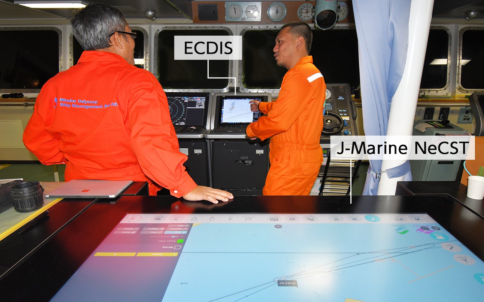
- Sensor, antenna or transducer fouling, damage or misalignment causes unstable, missing or inaccurate data
- Power-supply or processor faults cause resets, blank displays or complete loss of indication
- Cable, connector or network faults cause intermittent data or loss of outputs to dependent bridge systems
- Incorrect configuration or calibration causes persistent disagreement with independent references
- Display, storage or software faults cause frozen values, alarms or unavailable navigation functions
- Real‑time fusion of multiple navigation sources without extra onboard hardware
- Automatic chart and software updates delivered via the cloud
- Scalable subscription model lets operators add modules such as weather or route optimisation as needed
- Reduces shipboard IT footprint and power consumption compared with traditional standalone IBS solutions
- Enables remote monitoring, diagnostics and support from shore‑based teams
- Requires continuous high‑bandwidth internet; performance degrades in low‑coverage areas
- Ongoing subscription fees can become significant over the vessel's service life
- Data latency may affect time‑critical manoeuvres or collision avoidance
- Reliance on a third‑party cloud raises cybersecurity and data‑integrity concerns
- Limited functionality when offline; not a full standalone ECDIS replacement
MARINELEC
1
- Sensor, antenna or transducer fouling, damage or misalignment causes unstable, missing or inaccurate data
- Power-supply or processor faults cause resets, blank displays or complete loss of indication
- Cable, connector or network faults cause intermittent data or loss of outputs to dependent bridge systems
- Incorrect configuration or calibration causes persistent disagreement with independent references
- Display, storage or software faults cause frozen values, alarms or unavailable navigation functions
- Native French language support and documentation, easing training for European crews
- Strong integration with European‑type radars, ECDIS and AIS equipment
- Modular architecture allows selective upgrade of subsystems
- Compliance with EU maritime regulations out‑of‑the‑box
- Limited after‑sales service network outside France, leading to longer downtime for non‑European vessels
- Component sourcing can be difficult in regions without a local Marinelec distributor
- High integration complexity may require specialised engineering support during installation
- Potential compatibility issues with non‑European bridge hardware standards
OSI Maritime Systems
1- Sensor, antenna or transducer fouling, damage or misalignment causes unstable, missing or inaccurate data
- Power-supply or processor faults cause resets, blank displays or complete loss of indication
- Cable, connector or network faults cause intermittent data or loss of outputs to dependent bridge systems
- Incorrect configuration or calibration causes persistent disagreement with independent references
- Display, storage or software faults cause frozen values, alarms or unavailable navigation functions
- High level of sensor fusion meeting NATO STANAG requirements
- Modular architecture allows easy addition or replacement of displays and inputs
- Designed for harsh naval environments with proven redundancy and fault tolerance
- Integrated with combat management systems, enabling simultaneous navigation and tactical awareness
- Comprehensive training and support packages from OSI Maritime
- Significant upfront cost compared with commercial off‑the‑shelf bridge solutions
- Complex configuration and integration can extend project schedules
- Export control restrictions limit availability to certain countries
- Requires specialized naval crew training and maintenance expertise
- Limited applicability for civilian or merchant vessels
Raytheon Anschütz
1
- Sensor, antenna or transducer fouling, damage or misalignment causes unstable, missing or inaccurate data
- Power-supply or processor faults cause resets, blank displays or complete loss of indication
- Cable, connector or network faults cause intermittent data or loss of outputs to dependent bridge systems
- Incorrect configuration or calibration causes persistent disagreement with independent references
- Display, storage or software faults cause frozen values, alarms or unavailable navigation functions
- Modular architecture allows scaling from basic to full‑feature IBS on the same platform
- IMO approved solution meeting SOLAS requirements for integrated navigation systems
- Unified user interface across displays reduces crew training time and improves situational awareness
- Proven track record on a wide range of commercial vessels with long‑term support from Raytheon Anschütz
- Reported Synapsis bus communication errors can require specialist troubleshooting
- Workstation fans generate noticeable noise, especially in quiet bridge environments
- Configuration and integration complexity may increase installation time and cost
- Higher initial capital outlay compared with simpler stand‑alone ECDIS or radar units
Sperry Marine
1
- Sensor, antenna or transducer fouling, damage or misalignment causes unstable, missing or inaccurate data
- Power-supply or processor faults cause resets, blank displays or complete loss of indication
- Cable, connector or network faults cause intermittent data or loss of outputs to dependent bridge systems
- Incorrect configuration or calibration causes persistent disagreement with independent references
- Display, storage or software faults cause frozen values, alarms or unavailable navigation functions
- Proven track record on a wide range of commercial vessels
- Highly modular – individual radar or display modules can be added or replaced
- Full IMO type approval and USCG certification for bridge integration
- Supports legacy sensors while allowing upgrade to VisionMaster FT software platform
- Reduces crew workload by presenting all navigation data on common displays
- Hardware based on older processor architecture – increasing risk of component obsolescence
- Known reliability issues with certain multi‑function display units and network switches
- Limited processing capacity compared with newer VisionMaster FT systems
- Retrofit can be costly if extensive cabling or sensor replacement is required
- Vendor support for original IBS hardware is winding down as focus shifts to FT
Tokyo Keiki
1
- Sensor, antenna or transducer fouling, damage or misalignment causes unstable, missing or inaccurate data
- Power-supply or processor faults cause resets, blank displays or complete loss of indication
- Cable, connector or network faults cause intermittent data or loss of outputs to dependent bridge systems
- Incorrect configuration or calibration causes persistent disagreement with independent references
- Display, storage or software faults cause frozen values, alarms or unavailable navigation functions
- Native compatibility with Tokyo Keiki radars, gyrocompasses and AIS units, reducing integration effort on Japanese/Korean builds
- Modular software architecture allows addition of extra displays or functions without major re‑engineering
- Supports IEC 61162 (NMEA 0183/2000) data standards for sensor input
- Proven reliability in high‑traffic Asian domestic routes
- Comes with Japanese‑language technical support and training resources
- Limited global after‑sales service network; spare parts and field support are concentrated in Japan/Korea
- Documentation primarily in Japanese, which can hinder non‑Japanese crews and engineers
- Integration challenges when mixing third‑party sensors that are not from Tokyo Keiki
- Higher upfront cost compared with some Western IBS solutions that target a broader market
- Software updates may be released on a schedule aligned with Japanese shipyard projects rather than continuous OTA patches
Zetechtics
1- Sensor, antenna or transducer fouling, damage or misalignment causes unstable, missing or inaccurate data
- Power-supply or processor faults cause resets, blank displays or complete loss of indication
- Cable, connector or network faults cause intermittent data or loss of outputs to dependent bridge systems
- Incorrect configuration or calibration causes persistent disagreement with independent references
- Display, storage or software faults cause frozen values, alarms or unavailable navigation functions
- Provides a single visual platform for multiple navigation sources, reducing operator workload
- Designed for integration with standard IBS/INS architectures
- UK‑based manufacturer offers local technical support and service
- High‑resolution LCD panel suitable for detailed chart work
- Reported reliability issues with the underlying panel PC hardware
- Touchscreen performance can be inconsistent, especially in wet or gloved conditions
- Vibration from mounting may affect long‑term stability on high‑speed vessels
- Limited publicly documented certifications compared with larger OEMs