What to check on a LNG Fuel Gas Supply System.
The fuel gas supply system is separate from cargo containment even on a gas carrier: it draws LNG from a dedicated fuel tank, not from cargo tanks, and delivers it to dual-fuel engines or gas combustion units at the pressure and temperature each engine type needs. High-pressure two-stroke engines need gas near 300 bar, while low-pressure four-stroke or Otto-cycle engines need gas around 5-16 bar, and that pressure requirement is the single biggest factor separating one fuel gas system design from another.
What sets the fuel gas supply system apart
The fuel gas supply system is separate from cargo containment even on a gas carrier: it draws LNG from a dedicated fuel tank, not from cargo tanks, and delivers it to dual-fuel engines or gas combustion units at the pressure and temperature each engine type needs. High-pressure two-stroke engines need gas near 300 bar, while low-pressure four-stroke or Otto-cycle engines need gas around 5-16 bar, and that pressure requirement is the single biggest factor separating one fuel gas system design from another.
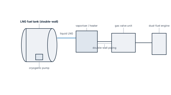
Main components
Fuel tank and cold box
A Type C pressure vessel or membrane tank holds LNG at around -162°C, insulated to keep boil-off low over weeks between bunkering. The cold box houses the cryogenic valves and instrumentation close to the tank in a sealed, ventilated enclosure.
Fuel gas pump or vaporiser train
High-pressure systems use submerged cryogenic pumps to raise LNG to working pressure while still liquid, then vaporise it downstream; low-pressure systems more often vaporise first and compress gas afterward. The choice drives most of the rest of the equipment list.
Gas Valve Unit (GVU) / Gas Valve Train (GVT)
A dedicated, double-walled ventilated enclosure containing shutoff, venting and pressure control valves for each engine, positioned so a single failure cannot release gas into the engine room. This unit is the interface class rules focus on most closely.
Nitrogen purge and double-wall piping
Gas fuel pipes running through machinery spaces are double-walled, with the annular space kept under inert gas purge or ventilated to detect any leak from the inner pipe before it reaches the engine room atmosphere.
Selection and sizing
| Factor | Effect on system design |
|---|---|
| Engine type — high or low pressure | Sets pump vs. compressor architecture and pipe pressure rating |
| Fuel tank hold time / boil-off rate | Determines whether boil-off gas alone can supply the engines or forced vaporisation is needed |
| Number and location of consumers | Drives GVU sizing and how many independent gas trains are fitted |
| Redundancy requirement for dual-fuel notation | May require full standby capability on the gas side, not just the fuel oil side |
Regulations and class
The IGF Code (International Code of Safety for Ships using Gases or other Low-flashpoint Fuels) governs fuel gas supply systems under SOLAS, covering tank location, double containment of gas piping in enclosed spaces, gas detection, and emergency shutdown arrangements. Class societies apply their own gas-fuelled ship notations on top of the IGF Code baseline, and periodic survey includes gas detection system testing, ESD valve function tests and inspection of the double-wall pipe annulus ventilation.
Typical faults
- Boil-off gas pressure control valve drifting — engine gas supply pressure fluctuates, forcing a fallback to fuel oil mode mid-voyage
- Cryogenic pump bearing wear from cavitation at low tank level — reduced high-pressure fuel gas flow limits engine load
- Double-wall annulus ventilation fan failure — a real inner-pipe leak goes undetected until gas reaches the engine room detector
- GVU purge nitrogen supply exhausted — automatic shutdown of the gas train even with no actual leak present, halting gas operation
What to look for in a supplier
- Type approval for the specific IGF Code notation and engine pressure class the vessel is built around
- Documented cooldown and gas-up procedure compatibility with the fuel tank supplier's own equipment
- Availability of cryogenic pump and valve spares at ports the vessel actually trades to, not just at the yard
- Reference installations on the same engine maker's dual-fuel platform, since GVU and engine control interfaces are not universal
Treat any gas detection alarm in the double-wall pipe annulus as a real leak until proven otherwise — the ventilation fan is there precisely because a slow inner-pipe leak gives almost no other warning before gas reaches the engine room.