Electrolysis BWTS
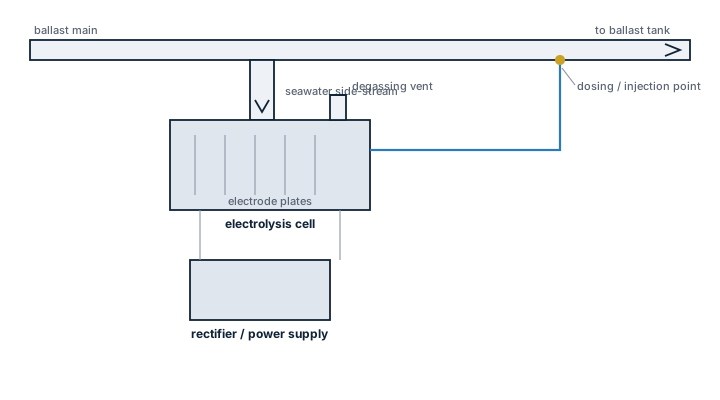
Electrolysis BWTS generate their own disinfectant by running an electric current through a side stream of seawater, which removes the need to carry chemical stock but ties treatment performance directly to salinity.
Read more — Electrolysis BWTS explained ▾
What makes this type
Electrochlorination systems pass a portion of the ballast flow through an electrolytic cell, splitting seawater into sodium hypochlorite and other oxidants that are then injected into the main ballast stream to disinfect it, before the residual is neutralised prior to discharge. The advantage over UV treatment is that performance is largely independent of water clarity, since the active substance does the work rather than light penetration, which makes electrolysis systems a common choice for ships regularly ballasting in turbid or sediment-heavy ports. The dependency it trades in is salinity: the electrolytic cell needs a minimum chloride concentration to generate enough oxidant, which is why fresh and brackish water performance is the main limitation of this type.
Main components
Filtration stage
A self-backwashing screen filter ahead of treatment removes larger organisms and debris, reducing organic load on the downstream disinfection stage.
Electrolytic cell
A side-stream of ballast water passes through electrode plates carrying a DC current, generating sodium hypochlorite from the chloride naturally present in seawater; the produced oxidant is then dosed into the main flow.
Dosing and mixing system
Metering pumps inject the generated oxidant into the main ballast line at a controlled concentration, with static mixers ensuring even distribution before the water reaches the tanks.
Neutralisation and residual control
Before discharge, a neutralising agent such as sodium bisulphite is dosed to bring total residual oxidant down to the level the D-2 standard and local discharge rules allow, monitored by an inline residual oxidant sensor.
Selection and sizing
Sizing follows the ship's maximum ballast flow rate the same as other BWTS types, but the electrolytic cell also has to be matched to the lowest salinity the ship regularly ballasts in; a cell sized only for open ocean seawater will underperform or fail to activate in brackish estuaries and needs a documented low-salinity operating mode or is simply unsuitable for that trade.
Regulations and class
- The IMO Ballast Water Management Convention requires an approved system on essentially all seagoing ships from the 2024 compliance deadline onward.
- Type approval under the BWMS Code confirms the system meets the D-2 discharge standard and, for active substance systems, includes a separate assessment of the chemicals produced under the Basic and Final Approval process for active substances.
- Residual oxidant discharge limits must be met at the point of discharge, verified during commissioning testing and periodic performance checks.
- Handling and storage of the neutralising chemical is subject to the ship's chemical safety data sheet requirements and crew PPE procedures.
Typical faults
| Fault | Consequence |
|---|---|
| Electrode scaling from calcium and magnesium deposits | Oxidant output drops, treatment falls short of D-2 requirement |
| Cell operated below its rated salinity threshold | Insufficient chlorine generated, organisms survive treatment |
| Neutralising agent dosing pump miscalibrated | Residual oxidant discharged above permitted limit |
| Residual oxidant sensor fouled or uncalibrated | False confidence in compliant discharge, undetected by the crew |
What to look for in a supplier
- Type approval documentation covering both the system and the active substance under the current BWMS Code cycle.
- A stated minimum operating salinity and, if the ship trades into brackish or fresh water, a genuine low-salinity mode rather than a marketing claim.
- Electrode cleaning or acid-wash procedure and spare electrode plate availability, since scaling is the main wear mechanism.
- Neutralising chemical supply chain reachable at the ship's regular ports, since this is a consumable, not a one-time purchase.
Log ballast source salinity alongside the treatment cycle every time; a compliance failure traced back months later is far easier to explain, and to fix, when the water's salinity at the time is already on record.
10 manufacturers · 30 models
Techcross
6
- Electrode erosion
- TRO sensor calibration drift
- Power supply failure
- Neutralization system malfunction
- IMO D-2 and USCG Type Approval confirmed for the model
- Compact unit suitable for retrofit installations
- No need for external chemical storage; chlorine is generated on‑site
- Integrated TRO sensor provides real‑time compliance monitoring
- Proven market presence with strong after‑sales support in Korea
- Electrode erosion requires scheduled replacement, increasing maintenance downtime
- TRO sensor can drift and needs periodic calibration
- Power supply failures have been reported, requiring robust electrical design
- Neutralization system malfunction may affect discharge quality if not monitored
- Higher electricity consumption compared with some UV‑based systems
- Treatment reactor, ultraviolet lamp or electrolytic-cell deterioration caused by aging, fouling or electrical faults, resulting in low treatment output or an alarm
- Filter blockage where fitted caused by sediment or biological loading, resulting in rising differential pressure, backflush cycling or reduced ballast flow
- Sensor or sampling fault caused by fouling, calibration drift or blocked lines, resulting in implausible readings or automatic treatment shutdown
- Valve, actuator or flow-control failure caused by corrosion, sticking or control faults, resulting in incorrect routing or insufficient treatment contact
- Control-system or communication failure caused by software, network or power-supply faults, resulting in unavailable automatic operation or persistent alarms
- Treatment reactor, ultraviolet lamp or electrolytic-cell deterioration caused by aging, fouling or electrical faults, resulting in low treatment output or an alarm
- Filter blockage where fitted caused by sediment or biological loading, resulting in rising differential pressure, backflush cycling or reduced ballast flow
- Sensor or sampling fault caused by fouling, calibration drift or blocked lines, resulting in implausible readings or automatic treatment shutdown
- Valve, actuator or flow-control failure caused by corrosion, sticking or control faults, resulting in incorrect routing or insufficient treatment contact
- Control-system or communication failure caused by software, network or power-supply faults, resulting in unavailable automatic operation or persistent alarms
- Fouling or exhausted treatment media can reduce treatment effectiveness, seen as deteriorating outlet-water quality or rising differential pressure
- Dosing-pump or chemical-feed faults can interrupt treatment, noticed as unstable readings, low dosing indication or quality alarms
- Blocked strainers or restricted piping can reduce flow, seen as low throughput or abnormal pump loading
- Sensor drift or contamination can give incorrect control feedback, noticed as implausible readings or unnecessary alarms
- Valve, seal or hose leakage can cause loss of treatment fluid or water, seen as wetness around the skid and inability to maintain normal operation
- Fouling or exhausted treatment media can reduce treatment effectiveness, seen as deteriorating outlet-water quality or rising differential pressure
- Dosing-pump or chemical-feed faults can interrupt treatment, noticed as unstable readings, low dosing indication or quality alarms
- Blocked strainers or restricted piping can reduce flow, seen as low throughput or abnormal pump loading
- Sensor drift or contamination can give incorrect control feedback, noticed as implausible readings or unnecessary alarms
- Valve, seal or hose leakage can cause loss of treatment fluid or water, seen as wetness around the skid and inability to maintain normal operation
- Fouling or exhausted treatment media can reduce treatment effectiveness, seen as deteriorating outlet-water quality or rising differential pressure
- Dosing-pump or chemical-feed faults can interrupt treatment, noticed as unstable readings, low dosing indication or quality alarms
- Blocked strainers or restricted piping can reduce flow, seen as low throughput or abnormal pump loading
- Sensor drift or contamination can give incorrect control feedback, noticed as implausible readings or unnecessary alarms
- Valve, seal or hose leakage can cause loss of treatment fluid or water, seen as wetness around the skid and inability to maintain normal operation
De Nora
5
- Filter blockage or automatic-backflush failure raises differential pressure and reduces ballast flow
- UV lamp, electrode or electrolysis-cell deterioration reduces treatment intensity and causes treatment alarms
- Low salinity, poor water quality or unsuitable process conditions causes reduced treatment effectiveness and system derating
- Sensor, flowmeter or analyzer faults cause incorrect dose or intensity control and prevent compliant operation
- Valve, dosing, neutralization or control faults cause bypass, failed sequence or discharge inhibition
- Filter blockage or automatic-backflush failure raises differential pressure and reduces ballast flow
- UV lamp, electrode or electrolysis-cell deterioration reduces treatment intensity and causes treatment alarms
- Low salinity, poor water quality or unsuitable process conditions causes reduced treatment effectiveness and system derating
- Sensor, flowmeter or analyzer faults cause incorrect dose or intensity control and prevent compliant operation
- Valve, dosing, neutralization or control faults cause bypass, failed sequence or discharge inhibition
- Filter blockage or automatic-backflush failure raises differential pressure and reduces ballast flow
- UV lamp, electrode or electrolysis-cell deterioration reduces treatment intensity and causes treatment alarms
- Low salinity, poor water quality or unsuitable process conditions causes reduced treatment effectiveness and system derating
- Sensor, flowmeter or analyzer faults cause incorrect dose or intensity control and prevent compliant operation
- Valve, dosing, neutralization or control faults cause bypass, failed sequence or discharge inhibition
- Filter blockage or automatic-backflush failure raises differential pressure and reduces ballast flow
- UV lamp, electrode or electrolysis-cell deterioration reduces treatment intensity and causes treatment alarms
- Low salinity, poor water quality or unsuitable process conditions causes reduced treatment effectiveness and system derating
- Sensor, flowmeter or analyzer faults cause incorrect dose or intensity control and prevent compliant operation
- Valve, dosing, neutralization or control faults cause bypass, failed sequence or discharge inhibition
Panasia
5
- Treatment reactor, ultraviolet lamp or electrolytic-cell deterioration caused by aging, fouling or electrical faults, resulting in low treatment output or an alarm
- Filter blockage where fitted caused by sediment or biological loading, resulting in rising differential pressure, backflush cycling or reduced ballast flow
- Sensor or sampling fault caused by fouling, calibration drift or blocked lines, resulting in implausible readings or automatic treatment shutdown
- Valve, actuator or flow-control failure caused by corrosion, sticking or control faults, resulting in incorrect routing or insufficient treatment contact
- Control-system or communication failure caused by software, network or power-supply faults, resulting in unavailable automatic operation or persistent alarms
- Treatment reactor, ultraviolet lamp or electrolytic-cell deterioration caused by aging, fouling or electrical faults, resulting in low treatment output or an alarm
- Filter blockage where fitted caused by sediment or biological loading, resulting in rising differential pressure, backflush cycling or reduced ballast flow
- Sensor or sampling fault caused by fouling, calibration drift or blocked lines, resulting in implausible readings or automatic treatment shutdown
- Valve, actuator or flow-control failure caused by corrosion, sticking or control faults, resulting in incorrect routing or insufficient treatment contact
- Control-system or communication failure caused by software, network or power-supply faults, resulting in unavailable automatic operation or persistent alarms
- Treatment reactor, ultraviolet lamp or electrolytic-cell deterioration caused by aging, fouling or electrical faults, resulting in low treatment output or an alarm
- Filter blockage where fitted caused by sediment or biological loading, resulting in rising differential pressure, backflush cycling or reduced ballast flow
- Sensor or sampling fault caused by fouling, calibration drift or blocked lines, resulting in implausible readings or automatic treatment shutdown
- Valve, actuator or flow-control failure caused by corrosion, sticking or control faults, resulting in incorrect routing or insufficient treatment contact
- Control-system or communication failure caused by software, network or power-supply faults, resulting in unavailable automatic operation or persistent alarms
- Treatment reactor, ultraviolet lamp or electrolytic-cell deterioration caused by aging, fouling or electrical faults, resulting in low treatment output or an alarm
- Filter blockage where fitted caused by sediment or biological loading, resulting in rising differential pressure, backflush cycling or reduced ballast flow
- Sensor or sampling fault caused by fouling, calibration drift or blocked lines, resulting in implausible readings or automatic treatment shutdown
- Valve, actuator or flow-control failure caused by corrosion, sticking or control faults, resulting in incorrect routing or insufficient treatment contact
- Control-system or communication failure caused by software, network or power-supply faults, resulting in unavailable automatic operation or persistent alarms
- Treatment reactor, ultraviolet lamp or electrolytic-cell deterioration caused by aging, fouling or electrical faults, resulting in low treatment output or an alarm
- Filter blockage where fitted caused by sediment or biological loading, resulting in rising differential pressure, backflush cycling or reduced ballast flow
- Sensor or sampling fault caused by fouling, calibration drift or blocked lines, resulting in implausible readings or automatic treatment shutdown
- Valve, actuator or flow-control failure caused by corrosion, sticking or control faults, resulting in incorrect routing or insufficient treatment contact
- Control-system or communication failure caused by software, network or power-supply faults, resulting in unavailable automatic operation or persistent alarms
Sunrui
5
- Filter blockage or backflush fault, typically indicated by high differential pressure, reduced ballast flow or alarm
- UV lamp/sleeve fouling or lamp failure, typically indicated by low UV intensity and treatment alarm
- Electrolytic cell scaling/fouling where applicable, typically indicated by low oxidant production, high current or treatment failure
- TRO/quality sensor drift or sample-line blockage, typically indicated by incorrect treatment/neutralization control
- Control/valve interlock fault, typically indicated by inability to enter treatment mode or automatic shutdown
- Filter blockage or backflush fault, typically indicated by high differential pressure, reduced ballast flow or alarm
- UV lamp/sleeve fouling or lamp failure, typically indicated by low UV intensity and treatment alarm
- Electrolytic cell scaling/fouling where applicable, typically indicated by low oxidant production, high current or treatment failure
- TRO/quality sensor drift or sample-line blockage, typically indicated by incorrect treatment/neutralization control
- Control/valve interlock fault, typically indicated by inability to enter treatment mode or automatic shutdown
- Filter blockage or backflush fault, typically indicated by high differential pressure, reduced ballast flow or alarm
- UV lamp/sleeve fouling or lamp failure, typically indicated by low UV intensity and treatment alarm
- Electrolytic cell scaling/fouling where applicable, typically indicated by low oxidant production, high current or treatment failure
- TRO/quality sensor drift or sample-line blockage, typically indicated by incorrect treatment/neutralization control
- Control/valve interlock fault, typically indicated by inability to enter treatment mode or automatic shutdown
- Filter blockage or backflush fault, typically indicated by high differential pressure, reduced ballast flow or alarm
- UV lamp/sleeve fouling or lamp failure, typically indicated by low UV intensity and treatment alarm
- Electrolytic cell scaling/fouling where applicable, typically indicated by low oxidant production, high current or treatment failure
- TRO/quality sensor drift or sample-line blockage, typically indicated by incorrect treatment/neutralization control
- Control/valve interlock fault, typically indicated by inability to enter treatment mode or automatic shutdown
- Filter blockage or backflush fault, typically indicated by high differential pressure, reduced ballast flow or alarm
- UV lamp/sleeve fouling or lamp failure, typically indicated by low UV intensity and treatment alarm
- Electrolytic cell scaling/fouling where applicable, typically indicated by low oxidant production, high current or treatment failure
- TRO/quality sensor drift or sample-line blockage, typically indicated by incorrect treatment/neutralization control
- Control/valve interlock fault, typically indicated by inability to enter treatment mode or automatic shutdown
Wärtsilä
4
- Filtration
- 40 Mikron Rückspülfilter mit automatischer Selbstreinigung, Differenzdrucksensor triggert automatischen Reinigungszyklus, modernes Manta-Filtersystem mit OneMotion-Scanner
- UV-Technologie (Aquarius UV)
- Mitteldruck-UV-Reaktor mit selbstreinigendem Quarzschlauch, mechanischer Wischer zur Leistungsverwaltung, 2-stufiger Prozess (Filtration + UV-Bestrahlung)
- EC-Technologie (Aquarius EC)
- Seitenstrom-Elektro-Chlorierung, statischer Mischer für Desinfektionsmittel-Injektion, maximale Dosierung 10 ppm Chlor im Ballastwasser
- Zulassungen
- IMO Typ-Zulassung (MEPC.300(72) ab 2019), USCG Typ-Zulassung, ATEX/IECEx für Aquarius UVX (Zone 1 IIC T4)
- Betrieb
- Fully automatic, minimal crew interaction (annual maintenance + monitoring only), user-friendly operation
- Aquarius UV
- Aquarius EC (Electro-Chlorination)
- Aquarius UVX (Zone 1 IIC T4 hazardous area)
- Area: UV lamp power loss due to ageing and wearCheck: Quarterly cleaning of quartz tubes, annual visual inspection of UV lamps, verification of UV intensity measurements by calibrated sensors, documentation of operating hours
- Area: Filter differential pressure rise due to dirt deposits and sensor failureCheck: Differential pressure sensor functional test (should automatically trigger backflush cycle at approx. 0.3 bar), visual inspection of filter element for damage/blockage, verification of differential pressure after backflushing (should reach < 0.1 bar)
- Area: UV intensity sensor miscalibration and malfunctionCheck: Annual sensor calibration (preferably by manufacturer), metric verification of measured UV intensity against reference values, isolation test of sensor against environmental influence, verification of alarm thresholds and signal transmission
- Area: Electrochlorination cell (EC systems) - wear and chemical effectivenessCheck: Verification of total residual chlorine (TRO) after treatment (must remain ≤ 0.1 mg/L), visual condition of EC cell for corrosion/wear, verification of static mixers for blockage, measurement of voltage ratios at EC electrodes
- Area: Automatic backflush valves and hydraulic malfunctionCheck: Functional test of automatic backflush valves (should respond reliably to sensor signal), visual inspection of all hydraulic lines and connections for leaks, verification of pump pressure regulator, flow rate verification against manufacturer specification
- Area: Certification and conformity documentationCheck: Verification of valid type approval certificates (IMO MEPC.300(72), USCG), control of ballast water record book with current entries, verification of conducted biological commissioning tests (required from 01.06.2022), verification of maintenance protocols and service records
Type-universal inspection/maintenance points for Ballast Water Treatment Systems (Wärtsilä, Mega-Schwarm 2026-06). Per-model-specs not auto-filled.
- Filtration
- 40 Mikron Rückspülfilter mit automatischer Selbstreinigung, Differenzdrucksensor triggert automatischen Reinigungszyklus, modernes Manta-Filtersystem mit OneMotion-Scanner
- UV-Technologie (Aquarius UV)
- Mitteldruck-UV-Reaktor mit selbstreinigendem Quarzschlauch, mechanischer Wischer zur Leistungsverwaltung, 2-stufiger Prozess (Filtration + UV-Bestrahlung)
- EC-Technologie (Aquarius EC)
- Seitenstrom-Elektro-Chlorierung, statischer Mischer für Desinfektionsmittel-Injektion, maximale Dosierung 10 ppm Chlor im Ballastwasser
- Zulassungen
- IMO Typ-Zulassung (MEPC.300(72) ab 2019), USCG Typ-Zulassung, ATEX/IECEx für Aquarius UVX (Zone 1 IIC T4)
- Betrieb
- Fully automatic, minimal crew interaction (annual maintenance + monitoring only), user-friendly operation
- Aquarius UV
- Aquarius EC (Electro-Chlorination)
- Aquarius UVX (Zone 1 IIC T4 hazardous area)
- Area: UV lamp power loss due to ageing and wearCheck: Quarterly cleaning of quartz tubes, annual visual inspection of UV lamps, verification of UV intensity measurements by calibrated sensors, documentation of operating hours
- Area: Filter differential pressure rise due to dirt deposits and sensor failureCheck: Differential pressure sensor functional test (should automatically trigger backflush cycle at approx. 0.3 bar), visual inspection of filter element for damage/blockage, verification of differential pressure after backflushing (should reach < 0.1 bar)
- Area: UV intensity sensor miscalibration and malfunctionCheck: Annual sensor calibration (preferably by manufacturer), metric verification of measured UV intensity against reference values, isolation test of sensor against environmental influence, verification of alarm thresholds and signal transmission
- Area: Electrochlorination cell (EC systems) - wear and chemical effectivenessCheck: Verification of total residual chlorine (TRO) after treatment (must remain ≤ 0.1 mg/L), visual condition of EC cell for corrosion/wear, verification of static mixers for blockage, measurement of voltage ratios at EC electrodes
- Area: Automatic backflush valves and hydraulic malfunctionCheck: Functional test of automatic backflush valves (should respond reliably to sensor signal), visual inspection of all hydraulic lines and connections for leaks, verification of pump pressure regulator, flow rate verification against manufacturer specification
- Area: Certification and conformity documentationCheck: Verification of valid type approval certificates (IMO MEPC.300(72), USCG), control of ballast water record book with current entries, verification of conducted biological commissioning tests (required from 01.06.2022), verification of maintenance protocols and service records
Type-universal inspection/maintenance points for Ballast Water Treatment Systems (Wärtsilä, Mega-Schwarm 2026-06). Per-model-specs not auto-filled.
- Filtration
- 40 Mikron Rückspülfilter mit automatischer Selbstreinigung, Differenzdrucksensor triggert automatischen Reinigungszyklus, modernes Manta-Filtersystem mit OneMotion-Scanner
- UV-Technologie (Aquarius UV)
- Mitteldruck-UV-Reaktor mit selbstreinigendem Quarzschlauch, mechanischer Wischer zur Leistungsverwaltung, 2-stufiger Prozess (Filtration + UV-Bestrahlung)
- EC-Technologie (Aquarius EC)
- Seitenstrom-Elektro-Chlorierung, statischer Mischer für Desinfektionsmittel-Injektion, maximale Dosierung 10 ppm Chlor im Ballastwasser
- Zulassungen
- IMO Typ-Zulassung (MEPC.300(72) ab 2019), USCG Typ-Zulassung, ATEX/IECEx für Aquarius UVX (Zone 1 IIC T4)
- Betrieb
- Fully automatic, minimal crew interaction (annual maintenance + monitoring only), user-friendly operation
- Aquarius UV
- Aquarius EC (Electro-Chlorination)
- Aquarius UVX (Zone 1 IIC T4 hazardous area)
- Area: UV lamp power loss due to ageing and wearCheck: Quarterly cleaning of quartz tubes, annual visual inspection of UV lamps, verification of UV intensity measurements by calibrated sensors, documentation of operating hours
- Area: Filter differential pressure rise due to dirt deposits and sensor failureCheck: Differential pressure sensor functional test (should automatically trigger backflush cycle at approx. 0.3 bar), visual inspection of filter element for damage/blockage, verification of differential pressure after backflushing (should reach < 0.1 bar)
- Area: UV intensity sensor miscalibration and malfunctionCheck: Annual sensor calibration (preferably by manufacturer), metric verification of measured UV intensity against reference values, isolation test of sensor against environmental influence, verification of alarm thresholds and signal transmission
- Area: Electrochlorination cell (EC systems) - wear and chemical effectivenessCheck: Verification of total residual chlorine (TRO) after treatment (must remain ≤ 0.1 mg/L), visual condition of EC cell for corrosion/wear, verification of static mixers for blockage, measurement of voltage ratios at EC electrodes
- Area: Automatic backflush valves and hydraulic malfunctionCheck: Functional test of automatic backflush valves (should respond reliably to sensor signal), visual inspection of all hydraulic lines and connections for leaks, verification of pump pressure regulator, flow rate verification against manufacturer specification
- Area: Certification and conformity documentationCheck: Verification of valid type approval certificates (IMO MEPC.300(72), USCG), control of ballast water record book with current entries, verification of conducted biological commissioning tests (required from 01.06.2022), verification of maintenance protocols and service records
Type-universal inspection/maintenance points for Ballast Water Treatment Systems (Wärtsilä, Mega-Schwarm 2026-06). Per-model-specs not auto-filled.
- Filtration
- 40 Mikron Rückspülfilter mit automatischer Selbstreinigung, Differenzdrucksensor triggert automatischen Reinigungszyklus, modernes Manta-Filtersystem mit OneMotion-Scanner
- UV-Technologie (Aquarius UV)
- Mitteldruck-UV-Reaktor mit selbstreinigendem Quarzschlauch, mechanischer Wischer zur Leistungsverwaltung, 2-stufiger Prozess (Filtration + UV-Bestrahlung)
- EC-Technologie (Aquarius EC)
- Seitenstrom-Elektro-Chlorierung, statischer Mischer für Desinfektionsmittel-Injektion, maximale Dosierung 10 ppm Chlor im Ballastwasser
- Zulassungen
- IMO Typ-Zulassung (MEPC.300(72) ab 2019), USCG Typ-Zulassung, ATEX/IECEx für Aquarius UVX (Zone 1 IIC T4)
- Betrieb
- Fully automatic, minimal crew interaction (annual maintenance + monitoring only), user-friendly operation
- Aquarius UV
- Aquarius EC (Electro-Chlorination)
- Aquarius UVX (Zone 1 IIC T4 hazardous area)
- Area: UV lamp power loss due to ageing and wearCheck: Quarterly cleaning of quartz tubes, annual visual inspection of UV lamps, verification of UV intensity measurements by calibrated sensors, documentation of operating hours
- Area: Filter differential pressure rise due to dirt deposits and sensor failureCheck: Differential pressure sensor functional test (should automatically trigger backflush cycle at approx. 0.3 bar), visual inspection of filter element for damage/blockage, verification of differential pressure after backflushing (should reach < 0.1 bar)
- Area: UV intensity sensor miscalibration and malfunctionCheck: Annual sensor calibration (preferably by manufacturer), metric verification of measured UV intensity against reference values, isolation test of sensor against environmental influence, verification of alarm thresholds and signal transmission
- Area: Electrochlorination cell (EC systems) - wear and chemical effectivenessCheck: Verification of total residual chlorine (TRO) after treatment (must remain ≤ 0.1 mg/L), visual condition of EC cell for corrosion/wear, verification of static mixers for blockage, measurement of voltage ratios at EC electrodes
- Area: Automatic backflush valves and hydraulic malfunctionCheck: Functional test of automatic backflush valves (should respond reliably to sensor signal), visual inspection of all hydraulic lines and connections for leaks, verification of pump pressure regulator, flow rate verification against manufacturer specification
- Area: Certification and conformity documentationCheck: Verification of valid type approval certificates (IMO MEPC.300(72), USCG), control of ballast water record book with current entries, verification of conducted biological commissioning tests (required from 01.06.2022), verification of maintenance protocols and service records
Type-universal inspection/maintenance points for Ballast Water Treatment Systems (Wärtsilä, Mega-Schwarm 2026-06). Per-model-specs not auto-filled.
Ecochlor
1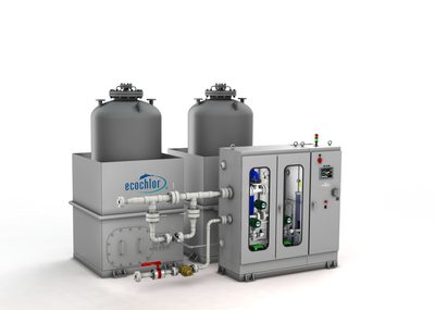
- ClO2 generator failure
- Chemical supply depletion
- Neutralization imbalance
- Dosing pump failure
- Proven biocidal efficacy against bacteria, viruses, algae and plankton
- No need for bulk storage of hazardous chlorine gas; generates disinfectant on‑demand
- IMO Type‑Approval (D‑2) and USCG type approval available for many models
- Compact modular design suitable for retrofits on a range of vessel sizes
- Requires continuous supply of sodium chlorite feedstock and periodic chemical resupply
- Electrolyser and dosing pump are mechanical components that can fail (generator or pump failures reported)
- Power consumption can be significant on low‑power vessels
- Neutralisation system must be carefully balanced to avoid excess chlorine dioxide discharge
JFE Engineering
1
- Electrode degradation
- Electrolysis cell scaling
- Control system failure
- Chemical‑free operation – no storage or handling of hazardous reagents
- Compact footprint suitable for retrofits on existing vessels
- Real‑time electrode life monitoring reduces unexpected downtime
- Low consumable cost after installation (no chemicals to purchase)
- Proven IMO D-2 approval indicating compliance with the international ballast water standard
- Electrode degradation over time requires scheduled replacement
- Scaling of electrolysis cells in high‑hardness waters can reduce efficiency
- Control system reliability issues reported; may need redundant monitoring
- Higher electrical power demand compared with some UV or filtration systems
- Performance can be sensitive to water chemistry variations
NK
1
- Electrode erosion
- TRO sensor drift
- Power supply failure
- Hydrogen gas ventilation issue
- Chemical‑free operation – no need for stored biocides or reagents
- Compact footprint suitable for vessels with limited installation space
- IMO D-2 approval provides direct compliance with the Ballast Water Management Convention
- Integrated hydrogen generation monitoring helps meet safety requirements
- Electrode erosion requires scheduled replacement and adds lifecycle cost
- TRO (Total Residual Oxidant) sensor drift can affect performance if not regularly calibrated
- High electrical power demand may be challenging for vessels with limited power margin
- Hydrogen gas venting must be carefully managed to avoid safety hazards
Panasonic (GS-YUASA)
1
- Electrode failure
- Control board malfunction
- TRO measurement error
- Compact footprint suitable for vessels with limited space
- No need to store or handle chemicals on board
- Automated control logic from a reputable electronics manufacturer
- Relatively low power consumption compared with thermal systems
- Straight‑forward installation and integration
- Electrode wear requires scheduled replacement
- Effectiveness can be reduced in water with high organic load or certain resistant organisms
- Known issues with control board reliability
- May lack IMO D‑2 certification without additional validation
- Performance depends on stable power supply and proper water chemistry
Samsung Heavy Industries
1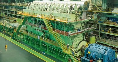
- Electrode wear
- TRO sensor failure
- Power module malfunction
- Chemical‑free operation – no storage or handling of biocides required
- Compact unit size suitable for vessels with limited installation space
- IMO D-2 approval confirming compliance with the Ballast Water Management Convention
- Proven track record on new builds at Korean shipyards, facilitating factory integration
- Relatively low consumable cost after initial installation
- Electrode wear necessitates scheduled replacement and associated downtime
- Sensitive to water quality; TRO (Total Residual Oxidant) sensor failures have been reported
- Higher electrical power demand compared with some UV‑based systems
- Power module malfunctions can require specialist support from the manufacturer
- Maintenance expertise for electrolysis components may be limited on vessels operating far from Korean yards