"> Shore Power System - Equipment Database

Shore Power System

medium 4 models total

Connecting a ship to shore power means synchronising two electrical systems that were never designed to share a load — the interlocking that prevents a mismatch is the part of the system that actually does the work.

Read more — Shore Power System explained

What sets a shore power system apart

Running the ship's generators is straightforward because the ship's own electrical network is a closed, known system. Shore power, sometimes called cold ironing, connects that network to a completely separate one ashore, which may run at a different voltage, a different frequency — 50 Hz ashore against 60 Hz on many ships built to US or Japanese standards — or simply be out of phase. A shore power system exists to make that connection safe: verifying voltage, frequency and phase match before closing the breaker, and preventing the ship's generators and the shore supply from ever being connected in parallel, which would let fault current flow both ways with no coordinated protection.
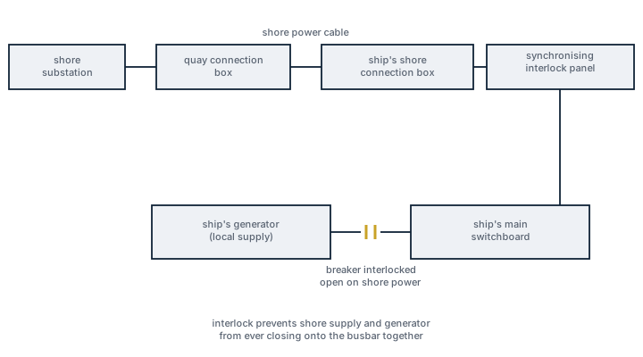
Shore power system, block schematic
Block diagram of a ship shore power connection: shore substation to quay connection box to the ship's shore inlet and synchronising interlock panel, feeding the main switchboard, with the ship's generator breaker shown interlocked open.

Main components

Shore connection box

The physical socket or cable reel on deck or at the terminal where the shore cable connects, sized for the ship's peak hotel load while alongside.

Frequency converter

Where shore frequency does not match the ship's own, a static or rotary converter bridges the gap, since running ship's equipment rated for 60 Hz directly off a 50 Hz shore supply changes motor speeds and can damage sensitive electronics.

Synchronising and interlock panel

Monitors shore voltage, frequency and phase rotation against the ship's bus before permitting closure of the shore breaker, and physically or electrically interlocks the shore breaker against the ship's generator breakers so the two sources cannot be paralleled.

Protection relays

Over and under voltage, over and under frequency and earth fault protection tuned to trip the shore connection without depending on shore-side protection settings the ship's crew cannot see or verify.

Selection and sizing

  • Peak hotel load while alongside, including cargo systems that continue running in port such as reefer plugs or inert gas systems.
  • Shore voltage and frequency standards at the ports the ship regularly calls, which decides whether a converter is needed at all.
  • Automated versus manual connection sequence — automated systems with robotic connection arms are increasingly required at terminals with strict turnaround times, particularly for container and cruise ports enforcing shore power use.
  • Cable handling arrangement: reel-mounted on the ship or supplied entirely from shore, which affects deck space and connection time.

Regulations and class

IEC/ISO/IEEE 80005 is the recognised standard covering high-voltage shore connection systems, split into parts for high-voltage systems, low-voltage systems and connectors. An increasing number of port and coastal authorities mandate shore power use at berth to cut local emissions, and MARPOL Annex VI's air emission provisions are the regulatory backdrop driving that shift, even though Annex VI itself does not mandate shore power equipment directly. Class societies require the interlock and protection scheme to be verified during commissioning and included in periodic electrical survey.

Typical faults

FaultConsequence
Interlock bypassed or defeated during a rushed connectionRisk of paralleling ship and shore supplies, producing uncontrolled fault current
Phase rotation not verified before closing the breakerReversed phase sequence trips or damages three-phase motors on the ship's bus
Frequency converter undersized for actual port loadConverter trips on overload, ship loses shore power mid-cargo operation
Cable connector wear from repeated handlingPoor contact, localized heating, a known fire risk at the connection point

What to look for in a supplier

  • Compliance with IEC/ISO/IEEE 80005 for the applicable voltage class rather than a proprietary interlock scheme.
  • Documented compatibility with the frequency and voltage standards at the ports the ship actually trades to.
  • Clear commissioning test records for the synchronising and interlock logic, since this is what a class surveyor will want to see first.

Never treat the interlock as a formality to work around during a slow connection — it is the only thing standing between shore power and an uncontrolled parallel fault.

Shore power
Shore power. Photo: Fabian Horst, CC BY-SA 4.0, via Wikimedia Commons

4 manufacturers · 4 models

ABB

1
Onshore Power Supply
Up to 20 MVA · Shore-to-Ship Power · Frequency converter shore power system
Type
Shore Power Supply
Common Failures & Inspection Points
  • Frequency converter fault
  • Transformer overheating
  • Protection relay miscoordination
  • Cable connection arcing
Service: Frequency conversion for multi-grid operation. Annual transformer oil test. Protection relay coordination study at installation.
Spare Parts: Ersatzteile über ABB oder zugelassene Vertriebspartner. Lead time: 2-6 Wochen.
Strengths
  • Integrated transformer and frequency converter enables operation on diverse grid voltages and frequencies
  • Modular design allows scalability and easy maintenance
  • Advanced protection relays provide high reliability and fault isolation
  • Built‑in monitoring supports condition‑based maintenance (e.g., oil testing)
  • Proven track record in major European ports
Weaknesses
  • High initial capital investment compared with simpler static converters
  • Large physical footprint requiring substantial shore‑side space
  • Requires periodic transformer oil testing and specialist servicing
  • Complex installation needing detailed protection coordination studies
  • Limited suitability for low‑power vessels where a smaller system would suffice
Typical Vessels: Container shipCruise linerTankerBulk carrierRo‑Ro ferry
Decision Guide: Choose if the port needs a versatile, high‑capacity solution that can handle multiple grid frequencies/voltages and values long‑term reliability. Avoid if budget or space constraints are critical, or if only low‑power shore power is required.
Use Cases: Deployed in busy international terminals where vessels of different classes and flag states require compliant shore power to meet emission regulations, such as European hub ports, North American Great Lakes terminals, and cruise ship berths.

Cavotec

1
Cavotec AMP (Alternative Maritime Power)
AMP (Alternative Maritime Power)
Up to 20 MVA · Shore-to-Ship Power · Automated high‑voltage shore connection
Type
Automated Shore Power
Technical Specifications
Spannungsbereich HV-Stecker
7.2 kV bis 15 kV verfügbar (Standard 12 kV)
Stromstärke
Bis 660 A (800 A Kapazität verfügbar)
Steckertyp
AMP-Hochspannungs-Stecker mit Push & Pull oder Schraubring-System
Schutzklasse verbunden
IP66 (Wetterschutz, Salzluft-resistent)
Materialien Stecker
Marine-Bronze-Nocken, rostfreier Stahl Steckerkörper
Isolationswiderstand Standard
Mind. 20 MΩ (Megohm), besser 1000+ MΩ
Insulation Test Spannung
500 V DC (Megger-Test)
Norm-Konformität
IEC/ISO/IEEE 80005-1, EU Directive 2014/94/EU
Erdungssystem
TN-Erdungssystem mit Schutzleiter-Kontinuität
Product Lines
  • PowerAMPReel - Onboard motorisierte Kabelspulanlage (HV/LV)
  • PowerFit HV - Containerisierte Komplettlösung für HVSC mit Transformator
  • PowerReceive - Schiffsseitige Anschlussbox für diverse Schiffstypen
  • PowerMove - Mobile Kabelmanagement-Systeme für Terminals (Cruise, RoPax, RoRo)
  • PowerRun - Kompaktes modulares Kabelspulensystem für kleinere Schiffe
  • PowerFeed - Ufergestützte Steckerboxen/Schnittstellen
  • PowerRange - Teleskop-Kabelmanagement für erweiterte Reichweite
Common Failures & Inspection Points
  • Area: Stecker/Kupplung Sichtkontrolle: Korrosion, Oxidation, Verfärbung
    Check: Visuelle Inspektion auf grüne Patina (Kupfer), schwarze Oxide (Silber), graubraune Verfärbung, Salzablagerungen; Oberflächenrauheit, Kratzer, Verformung an Kontakten prüfen. Leichte Oxidation mit Kontaktreinigungsspray behandeln; bei hartnäckiger Korrosion sanft mit Nylon-Bürste schrubben, niemals Stahlbürsten verwenden.
  • Area: Isolationswiderstand (Megger-Test) der Kabel und Stecker
    Check: Isolationswiderstandsprüfung mit Megger (500 V DC, 1 Minute) durchführen. Messwerte für Leitungen bis 5 A mindestens 2 MΩ, für >200 A mindestens 25 kΩ. Vor und nach Betrieb unter Vollast in kaltem und warmem Zustand messen. Werte unter 1000 MΩ sind kritisch; Trend-Analyse über Zeit durchführen zur Früherkennung von Verschleiß.
  • Area: Stecker-Kontaktwiderstand und Stiftkontakt-Verschleiß
    Check: Kontaktwiderstandsprüfung durchführen (Durchgangsprüfung); Kontaktflächen auf Abrieb, Verschleiß, Dellen, Kratzer überprüfen. Fretting-Korrosion (dunkles Abriebpulver an der Kontaktfläche) ist Zeichen verschlissener oder nicht optimal anliegender Kontakte. Bei Verschleiß Kontakte reinigen oder austauschen; Plug-in-Zyklen dokumentieren.
  • Area: Schutzleiter (PE)-Kontinuität und Erdung
    Check: Durchgangsprüfung der Schutzleiter mit <0.1 Ohm durchführen. Erdungsübergänge, Erdungskabel, Erdungsschiene und Schiff-zu-Ufer-Verbindung prüfen. Korrosion an Erdungsverbindungen (grüne/braune Verfärbung) entfernen. Alle Erdungspunkte fest angebracht und korrekt gekennzeichnet prüfen. Transfer Touch Potential und Galvanische Korrosion gemäß IEC 80005-1 Grounding Anforderungen kontrollieren.
  • Area: Kabelmanagement-System (Rolle, Lagerung, Schnelligkeit): Verschleiß an Rollen, Lagern, Umlenkrollen
    Check: Kabeltrommeln auf Riffelung, Verschleiß oder Verformung der Rillen prüfen (führt zu Kabelerschlaffung/Bruch). Lager und Achsen auf Verschleiß, Steifheit, Vibrationen kontrollieren; defekte Lager verursachen Reibung und Kabelbeschädigungen. Umlenkrollen auf Wobbeligkeit (verschlissene Buchsen/Lager) überprüfen. Rollen schmieren; beschädigte Rollen/Lager austauschen. Bei motorisierten Systemen (PowerAMPReel, PowerRun) Motor-Schaltungs- und Bremsenfunktion prüfen.
  • Area: Kabeloberfläche und Isolation: Beschädigungen, Feuchtigkeit, Alterung
    Check: Gesamte zugängliche Kabellänge auf sichtbare Beschädigungen, Verfärbung, Risse, abgelöste Isolation prüfen. Kabelstützen, Befestigungen und Korrosion überprüfen. Kabeleinführungen in Ausrüstungen auf ordnungsgemäße Versiegelung und Zugentlastung prüfen. Feuchtigkeitseintritt in Kabel erkennen (Quellungen, Wasserzeichen). Kabelverlegung auf zulässige Biegeradien, Überbelastung und Knicke kontrollieren. Biegeradius nicht unterschreiten; lose oder beschädigte Isolation zurückschneiden und neu verbinden.

Typ-universelle Inspektions-/Wartungspunkte fuer Shore Connection (Cavotec, Mega-Schwarm 2026-06). Per-Modell-Specs nicht auto-gefuellt.

Service: IEC/IEEE 80005-1 compliant. Annual plug contact inspection. Cable insulation test before connection.
Spare Parts: Ersatzteile über Cavotec oder zugelassene Vertriebspartner. Lead time: 2-6 Wochen.
Strengths
  • Fast power transfer thanks to 12 kV/660 A rating, reducing berth time for large vessels
  • Fully automated plug‑in/out (push‑&‑pull or screw‑ring) lowers crew workload and human error
  • IP66‑rated connector and marine‑grade materials resist salt‑air corrosion in harsh port environments
  • Modular product families (PowerAMPReel, PowerFit HV, etc.) allow tailoring to different vessel sizes and terminal layouts
  • Compliance with IEC/IEEE 80005‑1 and EU Directive 2014/94/EU ensures interoperability across ports
Weaknesses
  • High upfront capital cost and need for compatible high‑voltage shore infrastructure
  • Large physical footprint and weight may limit installation on smaller terminals
  • Maintenance requires specialized training (insulation resistance testing, plug wear monitoring)
  • Only suitable for vessels equipped for high‑voltage AC; low‑power ships would be over‑specified
Typical Vessels: Cruise shipRoPax ferryRoRo vesselLNG carrier (hotel load)Container ship with shore‑power capabilityLarge offshore support vessel
Certifications: IEC/IEEE 80005-1EU Directive 2014/94/EU
Decision Guide: Choose if the vessel has high hotel‑load demand, operates in ports equipped with 12 kV shore power, and the operator seeks to cut emissions and berth time. Avoid if only low‑voltage (LV) shore power is available, budget constraints preclude a high‑cost installation, or the ship lacks compatible HV equipment.
Use Cases: Installed at major cruise‑ship terminals, RoPax ferry berths, and container ports that provide green shore power to supply HVAC, lighting, and auxiliary systems while ships are docked, enabling zero‑emission operations on‑shore.

Schneider Electric

1
Shore Connection Panel
Up to 6.6 kV, 10 MVA · Shore-to-Ship Power · Shore power control panel
Type
Ship-Side Shore Panel
Common Failures & Inspection Points
  • Synchronization failure
  • Shore/ship breaker interlock fault
  • Transformer tap changer error
  • Cable termination overheating
Service: Ship-side equipment per IEC 80005. Test synchronization before each connection. Annual thermographic survey.
Spare Parts: Ersatzteile über Schneider Electric oder zugelassene Vertriebspartner. Lead time: 2-6 Wochen.
Strengths
  • Integrated synchronization function reduces risk of phase mismatch during hookup
  • Built‑in interlock and breaker protection meets IEC 80005 safety requirements
  • Modular design allows expansion for higher current or voltage classes
  • Remote monitoring interface compatible with vessel automation systems
  • Transformer tap changer provides flexible voltage adaptation to different ports
Weaknesses
  • Requires regular thermographic surveys and synchronization checks to avoid failures
  • Complex configuration may need specialist engineering support for high‑power vessels
  • Potential for breaker interlock faults if maintenance is neglected
  • Limited to the voltage/current ratings defined by the specific panel model
  • Initial capital cost higher than basic manual shore connectors
Typical Vessels: Container shipCruise linerRo‑Ro ferryOffshore supply vesselLNG carrier (when equipped for cold ironing)
Decision Guide: Choose if the vessel operates in ports with high‑capacity shore power, requires automated synchronization and continuous monitoring, and must meet IEC 80005 safety standards. Avoid if the ship only needs occasional low‑power connections or budget constraints preclude a modular, monitored system.
Use Cases: The panel is installed on vessels that perform cold ironing at berth to supply hotel loads, propulsion auxiliaries or cargo handling equipment from shore grids, thereby reducing emissions and fuel consumption while docked.

Siemens

1
SIHARBOR
Up to 25 MVA · Shore-to-Ship Power · SIPLINK frequency conversion
Type
Shore Power SIPLINK
Common Failures & Inspection Points
  • SIPLINK converter module fault
  • Cooling system failure
  • HMI communication error
  • Protection system trip
Service: SIPLINK technology for seamless 50/60 Hz conversion. Siemens service contract recommended.
Spare Parts: Ersatzteile über Siemens oder zugelassene Vertriebspartner. Lead time: 2-6 Wochen.
Strengths
  • Integrated 50 Hz/60 Hz conversion eliminates the need for separate converters on board.
  • Modular design allows scalable power ratings and easier maintenance of individual converter modules.
  • Built‑in HMI with remote diagnostics supports quick fault identification and reduces downtime.
  • Meets most international shore‑power standards, facilitating compliance in Emission Control Areas.
Weaknesses
  • Cooling system is complex and has been reported to fail if not regularly serviced.
  • SIPLINK converter module faults can cause a complete loss of power until replacement.
  • Higher initial capital cost compared with basic static shore‑power panels.
  • Requires dedicated space and infrastructure at the berth, which may be limited in older ports.
Typical Vessels: Cruise shipContainer vesselTankerFerryLNG carrier
Decision Guide: Choose if you need a reliable, high‑power shore connection with built‑in frequency conversion and advanced monitoring. Avoid if budget is tight, berth space is limited, or the port grid cannot support the system’s cooling and power requirements.
Use Cases: Deployed at ports that provide shore‑power to large passenger ships, container liners and tankers to reduce auxiliary engine emissions while docked, especially in Emission Control Areas where MARPOL Annex VI compliance is mandatory.