Variable Frequency Drive
A variable frequency drive controls an AC motor's speed by converting the fixed ship's supply to a variable frequency and voltage, letting pumps, fans and thrusters run at only the speed the process needs instead of full speed throttled back mechanically.
Read more — Variable Frequency Drive explained ▾
What Makes a Variable Frequency Drive Different
A variable frequency drive (VFD) rectifies the ship's fixed-frequency AC supply to DC and then inverts it back to AC at whatever frequency and voltage the connected motor needs, so the motor's speed follows the drive's output rather than running fixed at supply frequency. That is the fundamental difference from a soft starter, which only ramps voltage during starting and then passes the motor straight onto full-frequency supply, and from mechanical speed control such as a throttled valve or damper, which wastes energy forcing a full-speed pump or fan to deliver a reduced flow. A VFD instead slows the motor itself, cutting power consumption roughly with the cube of speed reduction for centrifugal loads like pumps and fans.
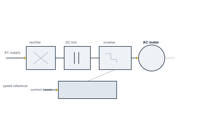
Main Components
Rectifier
Converts incoming three-phase AC to DC, either as a simple diode bridge or, on drives built to limit harmonic distortion fed back into the ship's supply, an active front end.
DC link
Smooths the rectified DC using capacitors and, on larger drives, an inductor; this stage also stores the energy that lets some drives ride through brief supply dips.
Inverter
Switches the DC back to AC at the commanded frequency and voltage using insulated-gate bipolar transistors (IGBTs), synthesizing the output waveform through pulse-width modulation.
Control electronics
Runs the motor control algorithm, scalar V/Hz control for simple loads or vector control for applications needing precise torque response such as thrusters, handles ramp rates, and interfaces with the ship's automation system.
Output filter
Often fitted between drive and motor on marine installations to reduce voltage stress on motor windings and limit electromagnetic interference in a steel hull full of sensitive electronics.
Selection and Sizing
- Motor power and voltage, with the drive rated for the motor's full load current plus margin for the expected duty cycle
- Control type needed; simple scalar control suffices for a fan or centrifugal pump, while a bow thruster or dynamic positioning drive needs vector control for accurate torque and speed response
- Harmonic mitigation, since multiple drives on one switchboard can distort the ship's supply enough to affect sensitive electronic equipment; active front ends or multi-pulse rectifiers reduce this
- Enclosure rating and cooling suited to the space, since engine room heat and vibration are harder on drive electronics than a dedicated switchroom
Regulations and Class
Classification societies require harmonic distortion on the ship's electrical network to stay within defined limits, which drives the choice of rectifier topology and any need for harmonic filters when several VFDs share a switchboard. Electromagnetic compatibility requirements apply to protect navigation and communication equipment from drive-generated interference. Drives on essential services need to meet the same redundancy and failure-mode requirements as the equipment they control; a thruster drive failing must not prevent manual fallback control where that is required.
Typical Faults
| Fault | Cause | Consequence |
|---|---|---|
| Nuisance overcurrent trips | Ramp rate set too aggressive for the driven load's inertia | Repeated trips, process interruption, operator frustration leads to overridden protection |
| Motor bearing damage | Shaft currents induced by fast switching without proper grounding or bearing insulation | Premature bearing failure, unexplained vibration |
| Interference with navigation equipment | Inadequate output filtering or poor cable screening between drive and motor | Compass or radio disturbance, difficult-to-trace intermittent faults elsewhere on the ship |
| Drive overheating and derating | Cooling fan failure or filter fouling in a hot engine room environment | Reduced output, unexpected trip under peak load |
What to Look for in a Supplier
- Marine type approval from the relevant classification society, not just an industrial-rated drive sold into a marine application
- Documented harmonic performance and, where several drives will share a switchboard, guidance on mitigation
- Vector control capability where the application needs precise torque response, such as thrusters or winches
- Enclosure and cooling rated for the actual installation environment, including vibration and ambient temperature
Check shaft grounding and bearing insulation whenever a VFD is retrofitted to an existing motor; the drive did not cause the bearing failure everyone blames it for, the missing grounding ring did.
5 manufacturers · 40 models
ABB
16- IGBT module failure from voltage spikes
- DC bus capacitor aging
- Cooling fan failure
- Control board communication error
- Marine‑certified design meeting IMO D‑2 and major classification societies
- Modular IGBT architecture with built‑in Safe Torque Off (STO) and other safety functions
- Robust dual‑fan cooling system with redundancy for continuous operation
- Easy integration and parameterisation via ABB DriveComposer software
- Proven reliability in high‑power (>5 MW) applications
- Large physical footprint and weight at the top end of the power range
- Periodic maintenance required: DC‑bus capacitor replacement (5–7 yr) and fan overhaul (≈3 yr)
- IGBT modules can be vulnerable to severe voltage spikes if not properly protected
- Higher upfront cost compared with lower‑power or generic industrial drives
- Firmware updates are mandatory to maintain compliance, adding operational overhead
- Input/output contactor failure
- EMC filter capacitor degradation
- Overheating from blocked ventilation
- Cost‑effective solution for standard‑duty loads
- Integrated EMC filter reduces harmonic emissions
- Optional marine‑grade coating protects against corrosion
- Compact footprint and high efficiency (~96 %)
- Predictable maintenance – cooling fans replaceable on a 3‑year schedule
- Not rated for heavy overload or extreme duty cycles
- Reported contactor failures require careful monitoring
- EMC filter capacitors can degrade over time
- Performance drops sharply if ventilation is obstructed, leading to overheating
- Limited to 250 kW – larger propulsion needs require a higher‑rated drive
Siemens
12
- Power module IGBT failure
- Control unit software fault
- Line reactor overheating
- Encoder feedback error
- Modular construction allows independent replacement of power or control modules, minimizing downtime.
- Marine‑certified (DNV) for harsh shipboard environments and vibration.
- Wide power range up to 250 kW with high efficiency and integrated safety functions.
- TIA Portal commissioning simplifies installation and parameterisation.
- Comprehensive diagnostics and fault logging aid preventive maintenance.
- Physical footprint larger than compact, non‑modular drives; may be challenging in tight engine rooms.
- Requires external line reactor; overheating of the reactor has been reported as a failure mode.
- IGBT power module failures have occurred in field service, requiring spare inventory.
- Higher upfront cost compared with basic VFDs lacking marine certification.
- Commissioning and troubleshooting demand experienced personnel familiar with Siemens TIA Portal.
- Active line module regeneration fault
- Motor module IGBT failure
- Encoder system fault
- CU320 control board failure
- Modular design allows easy replacement of faulty line or motor modules, reducing downtime.
- High power rating (up to 4500 kW) suitable for main propulsion on large vessels.
- Integrated safety and diagnostic functions meet marine classification requirements.
- Supports a wide range of voltage levels and motor types, providing flexibility in system design.
- Proven track record in demanding marine environments with Siemens service contracts available.
- Higher initial capital cost compared with lower‑power or less modular drives.
- Physical size and cooling requirements may be challenging on vessels with limited engine‑room space.
- Complex configuration can require specialized engineering support during installation.
- Known failure modes (e.g., line module regeneration fault, IGBT failure) demand vigilant condition monitoring.
Danfoss
10- DC link capacitor aging
- Relay output failure
- Software parameter corruption
- Cooling system degradation
- Integrated control functions (speed, torque, fault diagnostics) in a single unit
- Conformal‑coated electronics give superior resistance to humidity and salt spray
- DNV GL marine certification ensures compliance with offshore standards
- Modular design allows easy expansion or replacement of power modules
- High efficiency operation reduces fuel consumption on large vessels
- DC‑link capacitor bank requires scheduled replacement (≈5 years)
- Relays for auxiliary outputs can be prone to contact wear in harsh cycles
- Cooling system may degrade over time and needs regular inspection
- Physical footprint is relatively large compared with newer silicon‑carbide drives
- Software parameter sets can become corrupted, requiring backup procedures
- Fire mode relay failure
- BMS communication fault
- Motor thermistor input error
- Dedicated fire‑mode function meets ship safety requirements
- Integrated BMS interface simplifies building management system control
- Marine‑grade coating provides corrosion resistance in harsh sea environments
- Lower purchase price than general‑purpose drives of similar power
- Compact size eases installation in confined engine‑room or accommodation spaces
- Maximum rating of 90 kW limits use to smaller fans and pumps
- Limited advanced motor control features compared with higher‑end Danfoss drives
- Reported occasional fire‑mode relay and BMS communication faults
- Not suitable for propulsion, winch or high‑torque applications
- No built‑in sensorless vector control for variable torque loads
Vacon (Danfoss)
1
- Liquid cooling circuit leak
- IGBT module failure
- Control board I/O fault
- Brake chopper failure
- Very high power density reduces space and weight compared with air‑cooled drives
- Integrated liquid cooling provides superior thermal management for continuous high load operation
- Wide speed range and built‑in brake chopper enable precise control of propulsion and thrusters
- Marine‑class construction meets harsh vibration, humidity and shock requirements
- Global Danfoss service network ensures rapid spare parts and technical support
- Requires a dedicated liquid‑cooling circuit – adds complexity and risk of coolant leaks
- IGBT module replacement can be costly and may require specialized tools
- Higher upfront cost than comparable air‑cooled VFDs
- Control board I/O faults have been reported, necessitating careful wiring and grounding practices
- Brake chopper failures may occur if cooling is insufficient or if the system is frequently cycled
Yaskawa
1
- Main circuit capacitor aging
- Cooling fan failure
- Keypad communication error
- Overvoltage from regeneration
- Compact footprint saves valuable installation space on board
- Optional marine coating provides corrosion resistance in harsh sea environments
- Low total harmonic distortion (THD) improves power quality and reduces utility penalties
- Integrated regenerative capability with overvoltage protection enables energy recovery
- Multiple communication protocols (Modbus, CANopen, Profibus) simplify system integration
- Main‑circuit capacitors age and require replacement on a ~5‑year schedule
- Cooling fan failures have been reported; redundancy may be needed for critical applications
- Keypad or communication errors can occur, necessitating spare interface modules
- Regeneration overvoltage can stress upstream equipment if not properly managed
- Maximum power limited to 630 kW; larger propulsion demands may need multiple units or alternative drives