OceanSphere
Engines

MF/HF Radio

critical IMO Required 72 / 72 models (Inspector)

MF/HF radio is the GMDSS sea area A3/A4 fallback: DSC alerting and voice or NBDP traffic on 2 MHz and 4-27 MHz bands when a vessel is beyond VHF range or satellite coverage is unreliable at high latitude.

Read more — MF/HF Radio explained

What Sets MF/HF Apart

MF/HF radio covers the distance gap that VHF cannot close and the polar gap that geostationary satellite systems cannot cover. Where VHF is line-of-sight and drops out beyond roughly 20-30 nautical miles, MF (1.6-4 MHz) and HF (4-27 MHz) signals travel by ground wave and sky wave, bouncing off the ionosphere to reach hundreds or thousands of miles. This makes the set the primary GMDSS tool for sea areas A3 and A4, and the backup for A1/A2 vessels operating far offshore. Unlike Inmarsat terminals, MF/HF needs no satellite subscription and keeps working at latitudes above 70-76 degrees where geostationary coverage becomes marginal or unusable.
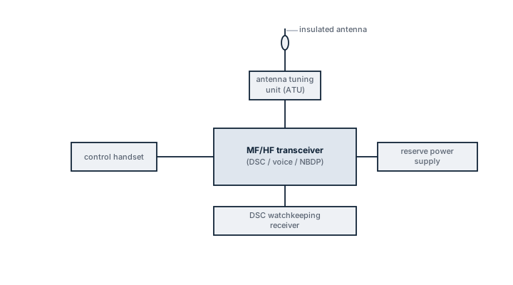
MF/HF radio installation
Block diagram of a GMDSS MF/HF radio station: insulated antenna through an antenna tuning unit to the transceiver handling DSC, voice and NBDP traffic, its separate DSC watchkeeping receiver, control handset and reserve power supply.

Main Components

Transceiver

The core unit generates and receives on the assigned distress, safety and working frequencies. It carries the DSC controller as an integrated module in most modern sets rather than a separate box.

Antenna Tuning Unit (ATU)

MF/HF whip or backstay antennas are electrically short relative to the transmitted wavelength, so an ATU matches impedance automatically each time the frequency changes. A failed ATU is the single most common reason a set transmits with high VSWR and low effective power.

Antenna

Usually an insulated backstay or a dedicated whip, kept clear of the VHF and radar antennas to limit mutual interference, with a solid, low-resistance ground plane connection to the hull.

DSC Watchkeeping Receiver

A separate scanning receiver continuously monitors 2187.5 kHz and the HF DSC distress and calling channels, independent of whether the operator is using the set for other traffic.

Selection and Sizing

  • Transmitter power: typically 150 W PEP for smaller vessels, up to 250 W PEP for larger ocean-going ships
  • Sea area rating: A3 fit is common; A4 (polar) operation needs full HF band coverage plus a working NBDP/telex capability
  • Number of installed antennas and available deck space for the ATU and ground plane
  • Integration with the ship's DSC alerting and GMDSS console, and available 24V/220V power redundancy

Regulations and Class

SOLAS Ch. IV sets the GMDSS carriage requirement by sea area; A3 vessels need MF/HF DSC capability unless they carry two independent Inmarsat terminals instead, and A4 vessels need it regardless. Class societies require an annual survey of the radio installation and verification against the ship's GMDSS Radio Log, and a battery-backed reserve source of energy able to power the set for a defined endurance period is mandatory.

Typical Faults

FaultConsequence
Corroded antenna feed or ground strapHigh VSWR, ATU cannot tune, reduced or lost transmit range
ATU relay contacts worn from cyclingSet locks on one frequency band or fails to tune at all
DSC watch receiver software faultDistress calls on other vessels go unanswered without the crew noticing
Reserve battery undercharged or agedSet drops out during a mains power failure, exactly when needed most

What to Look for in a Supplier

  • Type approval covering the vessel's actual GMDSS sea area, not just a general marine radio certificate
  • Documented VSWR and output power test results at handover, not just a visual inspection
  • Spare ATU relay and antenna coupler parts held in stock, since these fail more often than the transceiver itself
  • Experience integrating the set with the bridge's existing DSC alerting console

If the DSC watch receiver has not logged a self-test alarm in months, do not assume it is fine - test it deliberately, because a silent failure here means the ship stops listening for distress traffic without anyone knowing.

5 yr
Class Survey
15 yr
Typical Lifetime

Typical Manufacturers

Sailor (COBHAM) JRC Furuno
Inspector Mode Show All 72 / 72 with inspector value

9 manufacturers · 72 models

JRC (Japan Radio Co)

21
JHS-400 unverified
Power (W)
500
Dsc
ja
IMO Compliant
ja
Common Failures & Inspection Points
  • Loss of supply power from a tripped breaker, failed power unit, loose connection, or depleted reserve battery causes a dead unit, rebooting, or failure to transmit
  • Antenna, feeder, connector, or matching fault caused by corrosion, water ingress, or physical damage results in poor range, failed transmission, or weak received signals
  • Control-panel, display, keypad, or software faults can prevent channel selection, message handling, or normal operator input
  • Interface or position-data failure caused by wiring, configuration, or sensor faults can remove position information or connected-system data
  • Internal transmitter, receiver, or modem faults caused by component ageing or overheating can produce intermittent communication, alarms, or inability to establish a link
Service: Verify primary and reserve power, antenna and feeder condition, distress and safety functions permitted for routine testing, interfaces, audio quality, time and position inputs, and logged self-test results. Any regulatory test or adjustment must follow the vessel's radio procedures and manufacturer documentation.
Spare Parts: Carry the model-specific fuses, approved power-supply items, handset or microphone accessories, connector and sealing items, and critical interface or antenna components recommended by the manufacturer and vessel radio-maintenance plan.
Use Cases: Used on SOLAS merchant ships, offshore vessels, passenger ships, fishing vessels, workboats, and other craft requiring marine radio, distress, safety, or navigation communications.
JHS-400A unverified
Power (W)
500
Dsc
ja
IMO Compliant
ja
Common Failures & Inspection Points
  • Loss of supply power from a tripped breaker, failed power unit, loose connection, or depleted reserve battery causes a dead unit, rebooting, or failure to transmit
  • Antenna, feeder, connector, or matching fault caused by corrosion, water ingress, or physical damage results in poor range, failed transmission, or weak received signals
  • Control-panel, display, keypad, or software faults can prevent channel selection, message handling, or normal operator input
  • Interface or position-data failure caused by wiring, configuration, or sensor faults can remove position information or connected-system data
  • Internal transmitter, receiver, or modem faults caused by component ageing or overheating can produce intermittent communication, alarms, or inability to establish a link
Service: Verify primary and reserve power, antenna and feeder condition, distress and safety functions permitted for routine testing, interfaces, audio quality, time and position inputs, and logged self-test results. Any regulatory test or adjustment must follow the vessel's radio procedures and manufacturer documentation.
Spare Parts: Carry the model-specific fuses, approved power-supply items, handset or microphone accessories, connector and sealing items, and critical interface or antenna components recommended by the manufacturer and vessel radio-maintenance plan.
Use Cases: Used on SOLAS merchant ships, offshore vessels, passenger ships, fishing vessels, workboats, and other craft requiring marine radio, distress, safety, or navigation communications.
JSS-2150 unverified
Power (W)
150
Dsc
ja
IMO Compliant
ja
Common Failures & Inspection Points
  • Loss of supply power from a tripped breaker, failed power unit, loose connection, or depleted reserve battery causes a dead unit, rebooting, or failure to transmit
  • Antenna, feeder, connector, or matching fault caused by corrosion, water ingress, or physical damage results in poor range, failed transmission, or weak received signals
  • Control-panel, display, keypad, or software faults can prevent channel selection, message handling, or normal operator input
  • Interface or position-data failure caused by wiring, configuration, or sensor faults can remove position information or connected-system data
  • Internal transmitter, receiver, or modem faults caused by component ageing or overheating can produce intermittent communication, alarms, or inability to establish a link
Service: Verify primary and reserve power, antenna and feeder condition, distress and safety functions permitted for routine testing, interfaces, audio quality, time and position inputs, and logged self-test results. Any regulatory test or adjustment must follow the vessel's radio procedures and manufacturer documentation.
Spare Parts: Carry the model-specific fuses, approved power-supply items, handset or microphone accessories, connector and sealing items, and critical interface or antenna components recommended by the manufacturer and vessel radio-maintenance plan.
Use Cases: Used on SOLAS merchant ships, offshore vessels, passenger ships, fishing vessels, workboats, and other craft requiring marine radio, distress, safety, or navigation communications.
JSS-2250 unverified
Power (W)
250
Dsc
ja
IMO Compliant
ja
Common Failures & Inspection Points
  • Loss of supply power from a tripped breaker, failed power unit, loose connection, or depleted reserve battery causes a dead unit, rebooting, or failure to transmit
  • Antenna, feeder, connector, or matching fault caused by corrosion, water ingress, or physical damage results in poor range, failed transmission, or weak received signals
  • Control-panel, display, keypad, or software faults can prevent channel selection, message handling, or normal operator input
  • Interface or position-data failure caused by wiring, configuration, or sensor faults can remove position information or connected-system data
  • Internal transmitter, receiver, or modem faults caused by component ageing or overheating can produce intermittent communication, alarms, or inability to establish a link
Service: Verify primary and reserve power, antenna and feeder condition, distress and safety functions permitted for routine testing, interfaces, audio quality, time and position inputs, and logged self-test results. Any regulatory test or adjustment must follow the vessel's radio procedures and manufacturer documentation.
Spare Parts: Carry the model-specific fuses, approved power-supply items, handset or microphone accessories, connector and sealing items, and critical interface or antenna components recommended by the manufacturer and vessel radio-maintenance plan.
Use Cases: Used on SOLAS merchant ships, offshore vessels, passenger ships, fishing vessels, workboats, and other craft requiring marine radio, distress, safety, or navigation communications.
JSS-2500 unverified
Power (W)
500
Dsc
ja
IMO Compliant
ja
Common Failures & Inspection Points
  • Loss of supply power from a tripped breaker, failed power unit, loose connection, or depleted reserve battery causes a dead unit, rebooting, or failure to transmit
  • Antenna, feeder, connector, or matching fault caused by corrosion, water ingress, or physical damage results in poor range, failed transmission, or weak received signals
  • Control-panel, display, keypad, or software faults can prevent channel selection, message handling, or normal operator input
  • Interface or position-data failure caused by wiring, configuration, or sensor faults can remove position information or connected-system data
  • Internal transmitter, receiver, or modem faults caused by component ageing or overheating can produce intermittent communication, alarms, or inability to establish a link
Service: Verify primary and reserve power, antenna and feeder condition, distress and safety functions permitted for routine testing, interfaces, audio quality, time and position inputs, and logged self-test results. Any regulatory test or adjustment must follow the vessel's radio procedures and manufacturer documentation.
Spare Parts: Carry the model-specific fuses, approved power-supply items, handset or microphone accessories, connector and sealing items, and critical interface or antenna components recommended by the manufacturer and vessel radio-maintenance plan.
Use Cases: Used on SOLAS merchant ships, offshore vessels, passenger ships, fishing vessels, workboats, and other craft requiring marine radio, distress, safety, or navigation communications.
TG-34MKII unverified
Type
NBDP Terminal
IMO Compliant
ja
Common Failures & Inspection Points
  • Antenna, feeder or tuning fault caused by corrosion, damaged cabling or poor connections, resulting in weak transmission, reception problems or equipment alarms
  • Power-supply or backup-battery failure caused by charger defects, aged batteries or wiring faults, resulting in loss of availability when main power is removed
  • Transmitter or receiver failure caused by RF-component or electronic faults, resulting in inability to establish communications or receive expected traffic
  • Position or time-input failure caused by GNSS or network faults, resulting in missing or incorrect data in distress or DSC functions
  • Control, display or software fault caused by hardware failure or configuration problems, resulting in frozen controls, error messages or unavailable functions
Service: Perform operational and self-tests permitted by the vessel's procedures without generating unintended distress alerts. Inspect antennas, feeders, grounding, power supplies, backup batteries and connected navigation-data inputs. Verify station identity, position input, time and configured communication services against approved records. Check printers, handsets, microphones and alarm interfaces where fitted. Maintain software, licenses and service subscriptions required by the installed system. Refer to manufacturer and regulatory documentation for exact test methods, battery criteria and approved servicing.
Spare Parts: Keep fuses, handset or microphone accessories, printer consumables where applicable, selected power-supply components and manufacturer-recommended electronic spares. Antenna or feeder repair materials and backup-battery arrangements should reflect the vessel's redundancy plan. Preserve type approval and programmed identity when replacing core units.
Use Cases: Distress, urgency, safety and routine maritime communications within the vessel's GMDSS and operational communications fit.
DP-6A unverified
Type
NBDP Terminal
IMO Compliant
ja
Common Failures & Inspection Points
  • Transmitter or receiver failure caused by RF, antenna, feeder or power faults, noticed as poor range, failed checks or loss of reception
  • Antenna/feed-line deterioration caused by corrosion, water ingress or mechanical damage, noticed as intermittent operation or reduced range
  • Control or audio failure caused by handset, microphone, display, keypad or controller faults, noticed as inability to operate normal functions
  • Position/identity or data-interface failure caused by wiring or configuration faults, noticed as missing or incorrect safety data
  • Power-source failure caused by breaker, fuse, converter or emergency-supply faults, noticed as dead equipment or loss of required GMDSS availability
Service: Carry out the permitted operational/self-tests, inspect antennas, feeders, connectors, controls and cooling, and verify normal and emergency power where required. Check vessel identity, position and interfaces appropriate to the equipment type and review recurring alarms or logbook entries. A radio surveyor should confirm the installation and programmed data against the approved radio documentation.
Spare Parts: Carry fuses, approved handsets/microphones or control accessories where applicable, antenna connectors and feeder repair items, selected power-supply components and manufacturer-recommended interface/control spares. The spare scale should match the vessel's declared GMDSS maintenance method.
Use Cases: Used on merchant, offshore, passenger and workboat fleets for distress, safety and routine maritime communications according to the equipment's approved GMDSS function.
JSS-2150 Mk2 unverified
Dsc
ja
IMO Compliant
ja
Common Failures & Inspection Points
  • Antenna, tuner or grounding faults cause failed tuning, poor range or transmitter-protection alarms
  • Power-supply or emergency-power failure causes resets, blank displays or inability to transmit
  • Handset, microphone or audio-path faults cause weak or absent transmitted or received audio
  • DSC controller or interface faults prevent distress calling, scanning or message handling
  • Internal transmitter or receiver faults cause weak reception, no RF output or intermittent operation
Service: Inspect antennas, insulators, feeders, tuner, grounding, power supplies and operator controls. Test permitted voice and DSC functions and confirm emergency-power availability. Verify programmed ship identity and distress settings. RF alignment and measurements require approved service procedures.
Spare Parts: Carry fuses, handset or microphone parts, approved power-supply modules, antenna connectors, tuner-interface cables and selected control spares.
Use Cases: Ocean-going GMDSS vessels requiring medium- and long-range distress and operational communications.
JSS-2250 Mk2 unverified
Dsc
ja
IMO Compliant
ja
Common Failures & Inspection Points
  • Antenna, tuner or grounding faults cause failed tuning, poor range or transmitter-protection alarms
  • Power-supply or emergency-power failure causes resets, blank displays or inability to transmit
  • Handset, microphone or audio-path faults cause weak or absent transmitted or received audio
  • DSC controller or interface faults prevent distress calling, scanning or message handling
  • Internal transmitter or receiver faults cause weak reception, no RF output or intermittent operation
Service: Inspect antennas, insulators, feeders, tuner, grounding, power supplies and operator controls. Test permitted voice and DSC functions and confirm emergency-power availability. Verify programmed ship identity and distress settings. RF alignment and measurements require approved service procedures.
Spare Parts: Carry fuses, handset or microphone parts, approved power-supply modules, antenna connectors, tuner-interface cables and selected control spares.
Use Cases: Ocean-going GMDSS vessels requiring medium- and long-range distress and operational communications.
JSS-2500 Mk2 unverified
Dsc
ja
IMO Compliant
ja
Common Failures & Inspection Points
  • Antenna, tuner or grounding faults cause failed tuning, poor range or transmitter-protection alarms
  • Power-supply or emergency-power failure causes resets, blank displays or inability to transmit
  • Handset, microphone or audio-path faults cause weak or absent transmitted or received audio
  • DSC controller or interface faults prevent distress calling, scanning or message handling
  • Internal transmitter or receiver faults cause weak reception, no RF output or intermittent operation
Service: Inspect antennas, insulators, feeders, tuner, grounding, power supplies and operator controls. Test permitted voice and DSC functions and confirm emergency-power availability. Verify programmed ship identity and distress settings. RF alignment and measurements require approved service procedures.
Spare Parts: Carry fuses, handset or microphone parts, approved power-supply modules, antenna connectors, tuner-interface cables and selected control spares.
Use Cases: Ocean-going GMDSS vessels requiring medium- and long-range distress and operational communications.
JRC MF/HF 150W Compact unverified
Dsc
ja
IMO Compliant
ja
Common Failures & Inspection Points
  • Battery or power-supply deterioration caused by age, poor charging or connection faults can produce low-voltage alarms, failed self-tests or inability to transmit
  • Antenna, feeder or connector damage caused by corrosion, water ingress or mechanical stress can reduce range or prevent transmission and reception
  • Programming or configuration errors after replacement can produce identity, channel or communication faults even when the hardware powers up
  • Control, display or internal electronics faults caused by ageing or moisture can result in failed tests, unreadable indications or intermittent operation
  • Release, mounting or protective enclosure problems on emergency equipment caused by corrosion or damage can prevent correct deployment or leave the unit physically insecure
Service: Check identification and programming against vessel records, inspect antennas, feeders, mounts and power sources, and perform only the approved self-tests or functional checks. Verify battery and release dates from the actual unit and service documentation rather than assuming intervals. Refer to manufacturer and statutory documentation for exact test procedures.
Spare Parts: Carry approved batteries only where shipboard replacement is permitted, together with fuses, handset or microphone accessories, connectors, protective covers and other maker-approved service items appropriate to the installed unit.
Use Cases: SOLAS ships and other vessels requiring distress alerting, search-and-rescue location, maritime safety information or routine marine radio communications.
JRC MF/HF 500W Heavy unverified
Dsc
ja
IMO Compliant
ja
Common Failures & Inspection Points
  • Loss of supply power from a tripped breaker, failed power unit, loose connection, or depleted reserve battery causes a dead unit, rebooting, or failure to transmit
  • Antenna, feeder, connector, or matching fault caused by corrosion, water ingress, or physical damage results in poor range, failed transmission, or weak received signals
  • Control-panel, display, keypad, or software faults can prevent channel selection, message handling, or normal operator input
  • Interface or position-data failure caused by wiring, configuration, or sensor faults can remove position information or connected-system data
  • Internal transmitter, receiver, or modem faults caused by component ageing or overheating can produce intermittent communication, alarms, or inability to establish a link
Service: Verify primary and reserve power, antenna and feeder condition, distress and safety functions permitted for routine testing, interfaces, audio quality, time and position inputs, and logged self-test results. Any regulatory test or adjustment must follow the vessel's radio procedures and manufacturer documentation.
Spare Parts: Carry the model-specific fuses, approved power-supply items, handset or microphone accessories, connector and sealing items, and critical interface or antenna components recommended by the manufacturer and vessel radio-maintenance plan.
Use Cases: Used on SOLAS merchant ships, offshore vessels, passenger ships, fishing vessels, workboats, and other craft requiring marine radio, distress, safety, or navigation communications.
JSS-2150 Main Station unverified
Installation
Main Station
Common Failures & Inspection Points
  • Battery or power-supply deterioration caused by age, poor charging or connection faults can produce low-voltage alarms, failed self-tests or inability to transmit
  • Antenna, feeder or connector damage caused by corrosion, water ingress or mechanical stress can reduce range or prevent transmission and reception
  • Programming or configuration errors after replacement can produce identity, channel or communication faults even when the hardware powers up
  • Control, display or internal electronics faults caused by ageing or moisture can result in failed tests, unreadable indications or intermittent operation
  • Release, mounting or protective enclosure problems on emergency equipment caused by corrosion or damage can prevent correct deployment or leave the unit physically insecure
Service: Check identification and programming against vessel records, inspect antennas, feeders, mounts and power sources, and perform only the approved self-tests or functional checks. Verify battery and release dates from the actual unit and service documentation rather than assuming intervals. Refer to manufacturer and statutory documentation for exact test procedures.
Spare Parts: Carry approved batteries only where shipboard replacement is permitted, together with fuses, handset or microphone accessories, connectors, protective covers and other maker-approved service items appropriate to the installed unit.
Use Cases: SOLAS ships and other vessels requiring distress alerting, search-and-rescue location, maritime safety information or routine marine radio communications.
JSS-2250 Main Station unverified
Installation
Main Station
Common Failures & Inspection Points
  • Battery or power-supply deterioration caused by age, poor charging or connection faults can produce low-voltage alarms, failed self-tests or inability to transmit
  • Antenna, feeder or connector damage caused by corrosion, water ingress or mechanical stress can reduce range or prevent transmission and reception
  • Programming or configuration errors after replacement can produce identity, channel or communication faults even when the hardware powers up
  • Control, display or internal electronics faults caused by ageing or moisture can result in failed tests, unreadable indications or intermittent operation
  • Release, mounting or protective enclosure problems on emergency equipment caused by corrosion or damage can prevent correct deployment or leave the unit physically insecure
Service: Check identification and programming against vessel records, inspect antennas, feeders, mounts and power sources, and perform only the approved self-tests or functional checks. Verify battery and release dates from the actual unit and service documentation rather than assuming intervals. Refer to manufacturer and statutory documentation for exact test procedures.
Spare Parts: Carry approved batteries only where shipboard replacement is permitted, together with fuses, handset or microphone accessories, connectors, protective covers and other maker-approved service items appropriate to the installed unit.
Use Cases: SOLAS ships and other vessels requiring distress alerting, search-and-rescue location, maritime safety information or routine marine radio communications.
JSS-2500 Main Station unverified
Installation
Main Station
Common Failures & Inspection Points
  • Battery or power-supply deterioration caused by age, poor charging or connection faults can produce low-voltage alarms, failed self-tests or inability to transmit
  • Antenna, feeder or connector damage caused by corrosion, water ingress or mechanical stress can reduce range or prevent transmission and reception
  • Programming or configuration errors after replacement can produce identity, channel or communication faults even when the hardware powers up
  • Control, display or internal electronics faults caused by ageing or moisture can result in failed tests, unreadable indications or intermittent operation
  • Release, mounting or protective enclosure problems on emergency equipment caused by corrosion or damage can prevent correct deployment or leave the unit physically insecure
Service: Check identification and programming against vessel records, inspect antennas, feeders, mounts and power sources, and perform only the approved self-tests or functional checks. Verify battery and release dates from the actual unit and service documentation rather than assuming intervals. Refer to manufacturer and statutory documentation for exact test procedures.
Spare Parts: Carry approved batteries only where shipboard replacement is permitted, together with fuses, handset or microphone accessories, connectors, protective covers and other maker-approved service items appropriate to the installed unit.
Use Cases: SOLAS ships and other vessels requiring distress alerting, search-and-rescue location, maritime safety information or routine marine radio communications.
JSS-2150 Emergency Station unverified
Installation
Emergency Station
Common Failures & Inspection Points
  • Loss of primary or reserve power from a tripped breaker, failed power unit, loose connection, or depleted battery causes a dead unit, rebooting, or failed transmission
  • Antenna, feeder, connector, or matching faults from corrosion, water ingress, or physical damage cause poor range or weak received signals
  • Control-panel, display, keypad, or software faults prevent channel selection, message handling, or operator input
  • Interface or position-data failure from wiring, configuration, or sensor faults removes position or connected-system data
  • Internal transmitter, receiver, or modem faults from component ageing or overheating cause intermittent communication, alarms, or inability to establish a link
Service: Verify primary and reserve power, antenna and feeder condition, permitted distress/safety self-tests, interfaces, audio quality, time and position inputs, and logged faults. Regulatory tests and adjustments must follow vessel radio procedures and manufacturer documentation.
Spare Parts: Carry model-specific fuses, approved power-supply items, handset or microphone accessories where relevant, connector and sealing items, and critical interface or antenna components recommended by the manufacturer.
Use Cases: Used on SOLAS merchant ships, offshore vessels, passenger ships, fishing vessels, workboats, and other craft requiring marine radio, distress, safety, or navigation communications.
JSS-2250 Emergency Station unverified
Installation
Emergency Station
Common Failures & Inspection Points
  • Loss of primary or reserve power from a tripped breaker, failed power unit, loose connection, or depleted battery causes a dead unit, rebooting, or failed transmission
  • Antenna, feeder, connector, or matching faults from corrosion, water ingress, or physical damage cause poor range or weak received signals
  • Control-panel, display, keypad, or software faults prevent channel selection, message handling, or operator input
  • Interface or position-data failure from wiring, configuration, or sensor faults removes position or connected-system data
  • Internal transmitter, receiver, or modem faults from component ageing or overheating cause intermittent communication, alarms, or inability to establish a link
Service: Verify primary and reserve power, antenna and feeder condition, permitted distress/safety self-tests, interfaces, audio quality, time and position inputs, and logged faults. Regulatory tests and adjustments must follow vessel radio procedures and manufacturer documentation.
Spare Parts: Carry model-specific fuses, approved power-supply items, handset or microphone accessories where relevant, connector and sealing items, and critical interface or antenna components recommended by the manufacturer.
Use Cases: Used on SOLAS merchant ships, offshore vessels, passenger ships, fishing vessels, workboats, and other craft requiring marine radio, distress, safety, or navigation communications.
JSS-2500 Emergency Station unverified
Installation
Emergency Station
Common Failures & Inspection Points
  • Loss of primary or reserve power from a tripped breaker, failed power unit, loose connection, or depleted battery causes a dead unit, rebooting, or failed transmission
  • Antenna, feeder, connector, or matching faults from corrosion, water ingress, or physical damage cause poor range or weak received signals
  • Control-panel, display, keypad, or software faults prevent channel selection, message handling, or operator input
  • Interface or position-data failure from wiring, configuration, or sensor faults removes position or connected-system data
  • Internal transmitter, receiver, or modem faults from component ageing or overheating cause intermittent communication, alarms, or inability to establish a link
Service: Verify primary and reserve power, antenna and feeder condition, permitted distress/safety self-tests, interfaces, audio quality, time and position inputs, and logged faults. Regulatory tests and adjustments must follow vessel radio procedures and manufacturer documentation.
Spare Parts: Carry model-specific fuses, approved power-supply items, handset or microphone accessories where relevant, connector and sealing items, and critical interface or antenna components recommended by the manufacturer.
Use Cases: Used on SOLAS merchant ships, offshore vessels, passenger ships, fishing vessels, workboats, and other craft requiring marine radio, distress, safety, or navigation communications.
JSS-2150 Backup unverified
Installation
Backup
Common Failures & Inspection Points
  • Antenna, feeder or tuning fault caused by corrosion, damaged cabling or poor connections, resulting in weak transmission, reception problems or equipment alarms
  • Power-supply or backup-battery failure caused by charger defects, aged batteries or wiring faults, resulting in loss of availability when normal power is removed
  • Transmitter or receiver failure caused by RF-component or electronic faults, resulting in inability to establish communications or receive expected traffic
  • Position, time or identity-input problem caused by navigation-data or configuration faults, resulting in missing or incorrect information in distress or DSC functions
  • Control, display or software fault caused by hardware failure or configuration problems, resulting in frozen controls, error messages or unavailable functions
Service: Perform operational and self-tests permitted by the vessel's procedures without generating unintended distress alerts. Inspect antennas, feeders, grounding, power supplies, backup batteries and connected navigation-data inputs. Verify programmed station identity, position input, time and configured communication services against approved records. Check handsets, microphones, printers and alarm interfaces where fitted. Maintain software, licenses and service subscriptions required by the installed system. Refer to manufacturer and regulatory documentation for exact test methods, battery criteria and approved servicing.
Spare Parts: Keep fuses, handset or microphone accessories, printer consumables where applicable, selected power-supply components and manufacturer-recommended electronic spares. Antenna or feeder repair materials and backup-battery arrangements should reflect the vessel's redundancy plan. Preserve type approval and programmed identity when replacing core units.
Use Cases: Distress, urgency, safety and routine maritime communications within the vessel's GMDSS and operational communications fit.
JSS-2250 Backup unverified
Installation
Backup
Common Failures & Inspection Points
  • Antenna, feeder or tuning fault caused by corrosion, damaged cabling or poor connections, resulting in weak transmission, reception problems or equipment alarms
  • Power-supply or backup-battery failure caused by charger defects, aged batteries or wiring faults, resulting in loss of availability when normal power is removed
  • Transmitter or receiver failure caused by RF-component or electronic faults, resulting in inability to establish communications or receive expected traffic
  • Position, time or identity-input problem caused by navigation-data or configuration faults, resulting in missing or incorrect information in distress or DSC functions
  • Control, display or software fault caused by hardware failure or configuration problems, resulting in frozen controls, error messages or unavailable functions
Service: Perform operational and self-tests permitted by the vessel's procedures without generating unintended distress alerts. Inspect antennas, feeders, grounding, power supplies, backup batteries and connected navigation-data inputs. Verify programmed station identity, position input, time and configured communication services against approved records. Check handsets, microphones, printers and alarm interfaces where fitted. Maintain software, licenses and service subscriptions required by the installed system. Refer to manufacturer and regulatory documentation for exact test methods, battery criteria and approved servicing.
Spare Parts: Keep fuses, handset or microphone accessories, printer consumables where applicable, selected power-supply components and manufacturer-recommended electronic spares. Antenna or feeder repair materials and backup-battery arrangements should reflect the vessel's redundancy plan. Preserve type approval and programmed identity when replacing core units.
Use Cases: Distress, urgency, safety and routine maritime communications within the vessel's GMDSS and operational communications fit.
JSS-2500 Backup unverified
Installation
Backup
Common Failures & Inspection Points
  • Antenna, feeder or tuning fault caused by corrosion, damaged cabling or poor connections, resulting in weak transmission, reception problems or equipment alarms
  • Power-supply or backup-battery failure caused by charger defects, aged batteries or wiring faults, resulting in loss of availability when normal power is removed
  • Transmitter or receiver failure caused by RF-component or electronic faults, resulting in inability to establish communications or receive expected traffic
  • Position, time or identity-input problem caused by navigation-data or configuration faults, resulting in missing or incorrect information in distress or DSC functions
  • Control, display or software fault caused by hardware failure or configuration problems, resulting in frozen controls, error messages or unavailable functions
Service: Perform operational and self-tests permitted by the vessel's procedures without generating unintended distress alerts. Inspect antennas, feeders, grounding, power supplies, backup batteries and connected navigation-data inputs. Verify programmed station identity, position input, time and configured communication services against approved records. Check handsets, microphones, printers and alarm interfaces where fitted. Maintain software, licenses and service subscriptions required by the installed system. Refer to manufacturer and regulatory documentation for exact test methods, battery criteria and approved servicing.
Spare Parts: Keep fuses, handset or microphone accessories, printer consumables where applicable, selected power-supply components and manufacturer-recommended electronic spares. Antenna or feeder repair materials and backup-battery arrangements should reflect the vessel's redundancy plan. Preserve type approval and programmed identity when replacing core units.
Use Cases: Distress, urgency, safety and routine maritime communications within the vessel's GMDSS and operational communications fit.

Furuno

16
FS-1575
Frequency Range
MF/HF 1.6 - 27.5 MHz
TX Power
150 W
DSC Class
A
Type Approval
IMO A.806(19), IEC 61097-3/-7/-9
Area Coverage
GMDSS A2/A3/A4
Common Failures & Inspection Points
  • Antenna, tuner or grounding faults cause high reflected power, failed tuning, reduced range or transmitter protection alarms
  • Power-supply or emergency-power failure causes blank displays, resets or inability to transmit
  • Microphone, handset or audio-path faults cause poor or absent transmitted or received audio
  • DSC/controller or interface faults prevent distress calling, scanning or message handling and produce communication alarms
  • Internal transmitter or receiver faults cause weak reception, no RF output or intermittent operation
Service: Inspect antennas, insulators, feeders, tuner, grounding or counterpoise connections, power supplies and operator controls. Test routine voice and DSC functions using permitted procedures and confirm emergency-power availability. Verify programmed ship identity and distress settings. RF measurements and alignment require approved service equipment and manufacturer documentation.
Spare Parts: Carry fuses, handset or microphone parts, approved power-supply modules where practicable, antenna connectors, tuner-interface cables and selected control or display spares.
Use Cases: Ocean-going GMDSS vessels requiring medium- and long-range distress, safety and operational communications.
FS-2575
TX Power
250 W
Frequency Range
MF/HF 1.6 - 27.5 MHz
DSC Class
A
Type Approval
IMO A.806(19), IEC 61097-3/-7/-9
Common Failures & Inspection Points
  • Antenna, tuner or grounding faults cause high reflected power, failed tuning, reduced range or transmitter protection alarms
  • Power-supply or emergency-power failure causes blank displays, resets or inability to transmit
  • Microphone, handset or audio-path faults cause poor or absent transmitted or received audio
  • DSC/controller or interface faults prevent distress calling, scanning or message handling and produce communication alarms
  • Internal transmitter or receiver faults cause weak reception, no RF output or intermittent operation
Service: Inspect antennas, insulators, feeders, tuner, grounding or counterpoise connections, power supplies and operator controls. Test routine voice and DSC functions using permitted procedures and confirm emergency-power availability. Verify programmed ship identity and distress settings. RF measurements and alignment require approved service equipment and manufacturer documentation.
Spare Parts: Carry fuses, handset or microphone parts, approved power-supply modules where practicable, antenna connectors, tuner-interface cables and selected control or display spares.
Use Cases: Ocean-going GMDSS vessels requiring medium- and long-range distress, safety and operational communications.
FS-5075 unverified
Power (W)
500
Dsc
ja
IMO Compliant
ja
Common Failures & Inspection Points
  • Antenna, tuner or grounding faults cause high reflected power, failed tuning, reduced range or transmitter protection alarms
  • Power-supply or emergency-power failure causes blank displays, resets or inability to transmit
  • Microphone, handset or audio-path faults cause poor or absent transmitted or received audio
  • DSC/controller or interface faults prevent distress calling, scanning or message handling and produce communication alarms
  • Internal transmitter or receiver faults cause weak reception, no RF output or intermittent operation
Service: Inspect antennas, insulators, feeders, tuner, grounding or counterpoise connections, power supplies and operator controls. Test routine voice and DSC functions using permitted procedures and confirm emergency-power availability. Verify programmed ship identity and distress settings. RF measurements and alignment require approved service equipment and manufacturer documentation.
Spare Parts: Carry fuses, handset or microphone parts, approved power-supply modules where practicable, antenna connectors, tuner-interface cables and selected control or display spares.
Use Cases: Ocean-going GMDSS vessels requiring medium- and long-range distress, safety and operational communications.
FS-1575 Mk2 unverified
Dsc
ja
IMO Compliant
ja
Common Failures & Inspection Points
  • Antenna, tuner or grounding faults cause high reflected power, failed tuning, reduced range or transmitter protection alarms
  • Power-supply or emergency-power failure causes blank displays, resets or inability to transmit
  • Microphone, handset or audio-path faults cause poor or absent transmitted or received audio
  • DSC/controller or interface faults prevent distress calling, scanning or message handling and produce communication alarms
  • Internal transmitter or receiver faults cause weak reception, no RF output or intermittent operation
Service: Inspect antennas, insulators, feeders, tuner, grounding or counterpoise connections, power supplies and operator controls. Test routine voice and DSC functions using permitted procedures and confirm emergency-power availability. Verify programmed ship identity and distress settings. RF measurements and alignment require approved service equipment and manufacturer documentation.
Spare Parts: Carry fuses, handset or microphone parts, approved power-supply modules where practicable, antenna connectors, tuner-interface cables and selected control or display spares.
Use Cases: Ocean-going GMDSS vessels requiring medium- and long-range distress, safety and operational communications.
FS-2575 Mk2 unverified
Dsc
ja
IMO Compliant
ja
Common Failures & Inspection Points
  • Antenna, tuner or grounding faults cause high reflected power, failed tuning, reduced range or transmitter protection alarms
  • Power-supply or emergency-power failure causes blank displays, resets or inability to transmit
  • Microphone, handset or audio-path faults cause poor or absent transmitted or received audio
  • DSC/controller or interface faults prevent distress calling, scanning or message handling and produce communication alarms
  • Internal transmitter or receiver faults cause weak reception, no RF output or intermittent operation
Service: Inspect antennas, insulators, feeders, tuner, grounding or counterpoise connections, power supplies and operator controls. Test routine voice and DSC functions using permitted procedures and confirm emergency-power availability. Verify programmed ship identity and distress settings. RF measurements and alignment require approved service equipment and manufacturer documentation.
Spare Parts: Carry fuses, handset or microphone parts, approved power-supply modules where practicable, antenna connectors, tuner-interface cables and selected control or display spares.
Use Cases: Ocean-going GMDSS vessels requiring medium- and long-range distress, safety and operational communications.
FS-5075 Mk2 unverified
Dsc
ja
IMO Compliant
ja
Common Failures & Inspection Points
  • Antenna, tuner or grounding faults cause high reflected power, failed tuning, reduced range or transmitter protection alarms
  • Power-supply or emergency-power failure causes blank displays, resets or inability to transmit
  • Microphone, handset or audio-path faults cause poor or absent transmitted or received audio
  • DSC/controller or interface faults prevent distress calling, scanning or message handling and produce communication alarms
  • Internal transmitter or receiver faults cause weak reception, no RF output or intermittent operation
Service: Inspect antennas, insulators, feeders, tuner, grounding or counterpoise connections, power supplies and operator controls. Test routine voice and DSC functions using permitted procedures and confirm emergency-power availability. Verify programmed ship identity and distress settings. RF measurements and alignment require approved service equipment and manufacturer documentation.
Spare Parts: Carry fuses, handset or microphone parts, approved power-supply modules where practicable, antenna connectors, tuner-interface cables and selected control or display spares.
Use Cases: Ocean-going GMDSS vessels requiring medium- and long-range distress, safety and operational communications.
FS-1562 250W unverified
Dsc
ja
IMO Compliant
ja
Common Failures & Inspection Points
  • Antenna, tuner or grounding faults cause high reflected power, failed tuning, reduced range or transmitter protection alarms
  • Power-supply or emergency-power failure causes blank displays, resets or inability to transmit
  • Microphone, handset or audio-path faults cause poor or absent transmitted or received audio
  • DSC/controller or interface faults prevent distress calling, scanning or message handling and produce communication alarms
  • Internal transmitter or receiver faults cause weak reception, no RF output or intermittent operation
Service: Inspect antennas, insulators, feeders, tuner, grounding or counterpoise connections, power supplies and operator controls. Test routine voice and DSC functions using permitted procedures and confirm emergency-power availability. Verify programmed ship identity and distress settings. RF measurements and alignment require approved service equipment and manufacturer documentation.
Spare Parts: Carry fuses, handset or microphone parts, approved power-supply modules where practicable, antenna connectors, tuner-interface cables and selected control or display spares.
Use Cases: Ocean-going GMDSS vessels requiring medium- and long-range distress, safety and operational communications.
FS-1575 Main Station unverified
Installation
Main Station
Common Failures & Inspection Points
  • Transmitter or receiver failure caused by RF, antenna, feeder or power faults, noticed as poor range, failed checks or loss of reception
  • Antenna/feed-line deterioration caused by corrosion, water ingress or mechanical damage, noticed as intermittent operation or reduced range
  • Control or audio failure caused by handset, microphone, display, keypad or controller faults, noticed as inability to operate normal functions
  • Position/identity or data-interface failure caused by wiring or configuration faults, noticed as missing or incorrect safety data
  • Power-source failure caused by breaker, fuse, converter or emergency-supply faults, noticed as dead equipment or loss of required GMDSS availability
Service: Carry out the permitted operational/self-tests, inspect antennas, feeders, connectors, controls and cooling, and verify normal and emergency power where required. Check vessel identity, position and interfaces appropriate to the equipment type and review recurring alarms or logbook entries. A radio surveyor should confirm the installation and programmed data against the approved radio documentation.
Spare Parts: Carry fuses, approved handsets/microphones or control accessories where applicable, antenna connectors and feeder repair items, selected power-supply components and manufacturer-recommended interface/control spares. The spare scale should match the vessel's declared GMDSS maintenance method.
Use Cases: Used on merchant, offshore, passenger and workboat fleets for distress, safety and routine maritime communications according to the equipment's approved GMDSS function.
FS-2575 Main Station unverified
Installation
Main Station
Common Failures & Inspection Points
  • Transmitter or receiver failure caused by RF, antenna, feeder or power faults, noticed as poor range, failed checks or loss of reception
  • Antenna/feed-line deterioration caused by corrosion, water ingress or mechanical damage, noticed as intermittent operation or reduced range
  • Control or audio failure caused by handset, microphone, display, keypad or controller faults, noticed as inability to operate normal functions
  • Position/identity or data-interface failure caused by wiring or configuration faults, noticed as missing or incorrect safety data
  • Power-source failure caused by breaker, fuse, converter or emergency-supply faults, noticed as dead equipment or loss of required GMDSS availability
Service: Carry out the permitted operational/self-tests, inspect antennas, feeders, connectors, controls and cooling, and verify normal and emergency power where required. Check vessel identity, position and interfaces appropriate to the equipment type and review recurring alarms or logbook entries. A radio surveyor should confirm the installation and programmed data against the approved radio documentation.
Spare Parts: Carry fuses, approved handsets/microphones or control accessories where applicable, antenna connectors and feeder repair items, selected power-supply components and manufacturer-recommended interface/control spares. The spare scale should match the vessel's declared GMDSS maintenance method.
Use Cases: Used on merchant, offshore, passenger and workboat fleets for distress, safety and routine maritime communications according to the equipment's approved GMDSS function.
FS-5075 Main Station unverified
Installation
Main Station
Common Failures & Inspection Points
  • Transmitter or receiver failure caused by RF, antenna, feeder or power faults, noticed as poor range, failed checks or loss of reception
  • Antenna/feed-line deterioration caused by corrosion, water ingress or mechanical damage, noticed as intermittent operation or reduced range
  • Control or audio failure caused by handset, microphone, display, keypad or controller faults, noticed as inability to operate normal functions
  • Position/identity or data-interface failure caused by wiring or configuration faults, noticed as missing or incorrect safety data
  • Power-source failure caused by breaker, fuse, converter or emergency-supply faults, noticed as dead equipment or loss of required GMDSS availability
Service: Carry out the permitted operational/self-tests, inspect antennas, feeders, connectors, controls and cooling, and verify normal and emergency power where required. Check vessel identity, position and interfaces appropriate to the equipment type and review recurring alarms or logbook entries. A radio surveyor should confirm the installation and programmed data against the approved radio documentation.
Spare Parts: Carry fuses, approved handsets/microphones or control accessories where applicable, antenna connectors and feeder repair items, selected power-supply components and manufacturer-recommended interface/control spares. The spare scale should match the vessel's declared GMDSS maintenance method.
Use Cases: Used on merchant, offshore, passenger and workboat fleets for distress, safety and routine maritime communications according to the equipment's approved GMDSS function.
FS-1575 Emergency Station unverified
Installation
Emergency Station
Common Failures & Inspection Points
  • Antenna, tuner or grounding faults cause failed tuning, poor range or transmitter-protection alarms
  • Power-supply or emergency-power failure causes resets, blank displays or inability to transmit
  • Handset, microphone or audio-path faults cause weak or absent transmitted or received audio
  • DSC controller or interface faults prevent distress calling, scanning or message handling
  • Internal transmitter or receiver faults cause weak reception, no RF output or intermittent operation
Service: Inspect antennas, insulators, feeders, tuner, grounding, power supplies and operator controls. Test permitted voice and DSC functions and confirm emergency-power availability. Verify programmed ship identity and distress settings. RF alignment and measurements require approved service procedures.
Spare Parts: Carry fuses, handset or microphone parts, approved power-supply modules, antenna connectors, tuner-interface cables and selected control spares.
Use Cases: Ocean-going GMDSS vessels requiring medium- and long-range distress and operational communications.
FS-2575 Emergency Station unverified
Installation
Emergency Station
Common Failures & Inspection Points
  • Antenna, tuner or grounding faults cause failed tuning, poor range or transmitter-protection alarms
  • Power-supply or emergency-power failure causes resets, blank displays or inability to transmit
  • Handset, microphone or audio-path faults cause weak or absent transmitted or received audio
  • DSC controller or interface faults prevent distress calling, scanning or message handling
  • Internal transmitter or receiver faults cause weak reception, no RF output or intermittent operation
Service: Inspect antennas, insulators, feeders, tuner, grounding, power supplies and operator controls. Test permitted voice and DSC functions and confirm emergency-power availability. Verify programmed ship identity and distress settings. RF alignment and measurements require approved service procedures.
Spare Parts: Carry fuses, handset or microphone parts, approved power-supply modules, antenna connectors, tuner-interface cables and selected control spares.
Use Cases: Ocean-going GMDSS vessels requiring medium- and long-range distress and operational communications.
FS-5075 Emergency Station unverified
Installation
Emergency Station
Common Failures & Inspection Points
  • Antenna, tuner or grounding faults cause failed tuning, poor range or transmitter-protection alarms
  • Power-supply or emergency-power failure causes resets, blank displays or inability to transmit
  • Handset, microphone or audio-path faults cause weak or absent transmitted or received audio
  • DSC controller or interface faults prevent distress calling, scanning or message handling
  • Internal transmitter or receiver faults cause weak reception, no RF output or intermittent operation
Service: Inspect antennas, insulators, feeders, tuner, grounding, power supplies and operator controls. Test permitted voice and DSC functions and confirm emergency-power availability. Verify programmed ship identity and distress settings. RF alignment and measurements require approved service procedures.
Spare Parts: Carry fuses, handset or microphone parts, approved power-supply modules, antenna connectors, tuner-interface cables and selected control spares.
Use Cases: Ocean-going GMDSS vessels requiring medium- and long-range distress and operational communications.
FS-1575 Backup unverified
Installation
Backup
Common Failures & Inspection Points
  • Antenna, tuner or grounding faults cause high reflected power, failed tuning, reduced range or transmitter protection alarms
  • Power-supply or emergency-power failure causes blank displays, resets or inability to transmit
  • Microphone, handset or audio-path faults cause poor or absent transmitted or received audio
  • DSC/controller or interface faults prevent distress calling, scanning or message handling and produce communication alarms
  • Internal transmitter or receiver faults cause weak reception, no RF output or intermittent operation
Service: Inspect antennas, insulators, feeders, tuner, grounding or counterpoise connections, power supplies and operator controls. Test routine voice and DSC functions using permitted procedures and confirm emergency-power availability. Verify programmed ship identity and distress settings. RF measurements and alignment require approved service equipment and manufacturer documentation.
Spare Parts: Carry fuses, handset or microphone parts, approved power-supply modules where practicable, antenna connectors, tuner-interface cables and selected control or display spares.
Use Cases: Ocean-going GMDSS vessels requiring medium- and long-range distress, safety and operational communications.
FS-2575 Backup unverified
Installation
Backup
Common Failures & Inspection Points
  • Antenna, tuner or grounding faults cause high reflected power, failed tuning, reduced range or transmitter protection alarms
  • Power-supply or emergency-power failure causes blank displays, resets or inability to transmit
  • Microphone, handset or audio-path faults cause poor or absent transmitted or received audio
  • DSC/controller or interface faults prevent distress calling, scanning or message handling and produce communication alarms
  • Internal transmitter or receiver faults cause weak reception, no RF output or intermittent operation
Service: Inspect antennas, insulators, feeders, tuner, grounding or counterpoise connections, power supplies and operator controls. Test routine voice and DSC functions using permitted procedures and confirm emergency-power availability. Verify programmed ship identity and distress settings. RF measurements and alignment require approved service equipment and manufacturer documentation.
Spare Parts: Carry fuses, handset or microphone parts, approved power-supply modules where practicable, antenna connectors, tuner-interface cables and selected control or display spares.
Use Cases: Ocean-going GMDSS vessels requiring medium- and long-range distress, safety and operational communications.
FS-5075 Backup unverified
Installation
Backup
Common Failures & Inspection Points
  • Antenna, tuner or grounding faults cause high reflected power, failed tuning, reduced range or transmitter protection alarms
  • Power-supply or emergency-power failure causes blank displays, resets or inability to transmit
  • Microphone, handset or audio-path faults cause poor or absent transmitted or received audio
  • DSC/controller or interface faults prevent distress calling, scanning or message handling and produce communication alarms
  • Internal transmitter or receiver faults cause weak reception, no RF output or intermittent operation
Service: Inspect antennas, insulators, feeders, tuner, grounding or counterpoise connections, power supplies and operator controls. Test routine voice and DSC functions using permitted procedures and confirm emergency-power availability. Verify programmed ship identity and distress settings. RF measurements and alignment require approved service equipment and manufacturer documentation.
Spare Parts: Carry fuses, handset or microphone parts, approved power-supply modules where practicable, antenna connectors, tuner-interface cables and selected control or display spares.
Use Cases: Ocean-going GMDSS vessels requiring medium- and long-range distress, safety and operational communications.

Sailor / Cobham

16
6300 MF-HF 150W unverified
Dsc
ja
IMO Compliant
ja
Common Failures & Inspection Points
  • Antenna, feeder or tuning fault caused by corrosion, damaged cabling or poor connections, resulting in weak transmission, reception problems or equipment alarms
  • Power-supply or backup-battery failure caused by charger defects, aged batteries or wiring faults, resulting in loss of availability when main power is removed
  • Transmitter or receiver failure caused by RF-component or electronic faults, resulting in inability to establish communications or receive expected traffic
  • Position or time-input failure caused by GNSS or network faults, resulting in missing or incorrect data in distress or DSC functions
  • Control, display or software fault caused by hardware failure or configuration problems, resulting in frozen controls, error messages or unavailable functions
Service: Perform operational and self-tests permitted by the vessel's procedures without generating unintended distress alerts. Inspect antennas, feeders, grounding, power supplies, backup batteries and connected navigation-data inputs. Verify station identity, position input, time and configured communication services against approved records. Check printers, handsets, microphones and alarm interfaces where fitted. Maintain software, licenses and service subscriptions required by the installed system. Refer to manufacturer and regulatory documentation for exact test methods, battery criteria and approved servicing.
Spare Parts: Keep fuses, handset or microphone accessories, printer consumables where applicable, selected power-supply components and manufacturer-recommended electronic spares. Antenna or feeder repair materials and backup-battery arrangements should reflect the vessel's redundancy plan. Preserve type approval and programmed identity when replacing core units.
Use Cases: Distress, urgency, safety and routine maritime communications within the vessel's GMDSS and operational communications fit.
6310 MF-HF 250W unverified
Dsc
ja
IMO Compliant
ja
Common Failures & Inspection Points
  • Antenna, feeder or tuning fault caused by corrosion, damaged cabling or poor connections, resulting in weak transmission, reception problems or equipment alarms
  • Power-supply or backup-battery failure caused by charger defects, aged batteries or wiring faults, resulting in loss of availability when main power is removed
  • Transmitter or receiver failure caused by RF-component or electronic faults, resulting in inability to establish communications or receive expected traffic
  • Position or time-input failure caused by GNSS or network faults, resulting in missing or incorrect data in distress or DSC functions
  • Control, display or software fault caused by hardware failure or configuration problems, resulting in frozen controls, error messages or unavailable functions
Service: Perform operational and self-tests permitted by the vessel's procedures without generating unintended distress alerts. Inspect antennas, feeders, grounding, power supplies, backup batteries and connected navigation-data inputs. Verify station identity, position input, time and configured communication services against approved records. Check printers, handsets, microphones and alarm interfaces where fitted. Maintain software, licenses and service subscriptions required by the installed system. Refer to manufacturer and regulatory documentation for exact test methods, battery criteria and approved servicing.
Spare Parts: Keep fuses, handset or microphone accessories, printer consumables where applicable, selected power-supply components and manufacturer-recommended electronic spares. Antenna or feeder repair materials and backup-battery arrangements should reflect the vessel's redundancy plan. Preserve type approval and programmed identity when replacing core units.
Use Cases: Distress, urgency, safety and routine maritime communications within the vessel's GMDSS and operational communications fit.
6320 MF-HF 500W unverified
Dsc
ja
IMO Compliant
ja
Common Failures & Inspection Points
  • Antenna, feeder or tuning fault caused by corrosion, damaged cabling or poor connections, resulting in weak transmission, reception problems or equipment alarms
  • Power-supply or backup-battery failure caused by charger defects, aged batteries or wiring faults, resulting in loss of availability when main power is removed
  • Transmitter or receiver failure caused by RF-component or electronic faults, resulting in inability to establish communications or receive expected traffic
  • Position or time-input failure caused by GNSS or network faults, resulting in missing or incorrect data in distress or DSC functions
  • Control, display or software fault caused by hardware failure or configuration problems, resulting in frozen controls, error messages or unavailable functions
Service: Perform operational and self-tests permitted by the vessel's procedures without generating unintended distress alerts. Inspect antennas, feeders, grounding, power supplies, backup batteries and connected navigation-data inputs. Verify station identity, position input, time and configured communication services against approved records. Check printers, handsets, microphones and alarm interfaces where fitted. Maintain software, licenses and service subscriptions required by the installed system. Refer to manufacturer and regulatory documentation for exact test methods, battery criteria and approved servicing.
Spare Parts: Keep fuses, handset or microphone accessories, printer consumables where applicable, selected power-supply components and manufacturer-recommended electronic spares. Antenna or feeder repair materials and backup-battery arrangements should reflect the vessel's redundancy plan. Preserve type approval and programmed identity when replacing core units.
Use Cases: Distress, urgency, safety and routine maritime communications within the vessel's GMDSS and operational communications fit.
6301 MF-HF 150W unverified
Dsc
ja
IMO Compliant
ja
Common Failures & Inspection Points
  • Antenna, feeder or tuning fault caused by corrosion, damaged cabling or poor connections, resulting in weak transmission, reception problems or equipment alarms
  • Power-supply or backup-battery failure caused by charger defects, aged batteries or wiring faults, resulting in loss of availability when main power is removed
  • Transmitter or receiver failure caused by RF-component or electronic faults, resulting in inability to establish communications or receive expected traffic
  • Position or time-input failure caused by GNSS or network faults, resulting in missing or incorrect data in distress or DSC functions
  • Control, display or software fault caused by hardware failure or configuration problems, resulting in frozen controls, error messages or unavailable functions
Service: Perform operational and self-tests permitted by the vessel's procedures without generating unintended distress alerts. Inspect antennas, feeders, grounding, power supplies, backup batteries and connected navigation-data inputs. Verify station identity, position input, time and configured communication services against approved records. Check printers, handsets, microphones and alarm interfaces where fitted. Maintain software, licenses and service subscriptions required by the installed system. Refer to manufacturer and regulatory documentation for exact test methods, battery criteria and approved servicing.
Spare Parts: Keep fuses, handset or microphone accessories, printer consumables where applicable, selected power-supply components and manufacturer-recommended electronic spares. Antenna or feeder repair materials and backup-battery arrangements should reflect the vessel's redundancy plan. Preserve type approval and programmed identity when replacing core units.
Use Cases: Distress, urgency, safety and routine maritime communications within the vessel's GMDSS and operational communications fit.
6311 MF-HF 250W unverified
Dsc
ja
IMO Compliant
ja
Common Failures & Inspection Points
  • Antenna, feeder or tuning fault caused by corrosion, damaged cabling or poor connections, resulting in weak transmission, reception problems or equipment alarms
  • Power-supply or backup-battery failure caused by charger defects, aged batteries or wiring faults, resulting in loss of availability when main power is removed
  • Transmitter or receiver failure caused by RF-component or electronic faults, resulting in inability to establish communications or receive expected traffic
  • Position or time-input failure caused by GNSS or network faults, resulting in missing or incorrect data in distress or DSC functions
  • Control, display or software fault caused by hardware failure or configuration problems, resulting in frozen controls, error messages or unavailable functions
Service: Perform operational and self-tests permitted by the vessel's procedures without generating unintended distress alerts. Inspect antennas, feeders, grounding, power supplies, backup batteries and connected navigation-data inputs. Verify station identity, position input, time and configured communication services against approved records. Check printers, handsets, microphones and alarm interfaces where fitted. Maintain software, licenses and service subscriptions required by the installed system. Refer to manufacturer and regulatory documentation for exact test methods, battery criteria and approved servicing.
Spare Parts: Keep fuses, handset or microphone accessories, printer consumables where applicable, selected power-supply components and manufacturer-recommended electronic spares. Antenna or feeder repair materials and backup-battery arrangements should reflect the vessel's redundancy plan. Preserve type approval and programmed identity when replacing core units.
Use Cases: Distress, urgency, safety and routine maritime communications within the vessel's GMDSS and operational communications fit.
6321 MF-HF 500W unverified
Dsc
ja
IMO Compliant
ja
Common Failures & Inspection Points
  • Antenna, feeder or tuning fault caused by corrosion, damaged cabling or poor connections, resulting in weak transmission, reception problems or equipment alarms
  • Power-supply or backup-battery failure caused by charger defects, aged batteries or wiring faults, resulting in loss of availability when main power is removed
  • Transmitter or receiver failure caused by RF-component or electronic faults, resulting in inability to establish communications or receive expected traffic
  • Position or time-input failure caused by GNSS or network faults, resulting in missing or incorrect data in distress or DSC functions
  • Control, display or software fault caused by hardware failure or configuration problems, resulting in frozen controls, error messages or unavailable functions
Service: Perform operational and self-tests permitted by the vessel's procedures without generating unintended distress alerts. Inspect antennas, feeders, grounding, power supplies, backup batteries and connected navigation-data inputs. Verify station identity, position input, time and configured communication services against approved records. Check printers, handsets, microphones and alarm interfaces where fitted. Maintain software, licenses and service subscriptions required by the installed system. Refer to manufacturer and regulatory documentation for exact test methods, battery criteria and approved servicing.
Spare Parts: Keep fuses, handset or microphone accessories, printer consumables where applicable, selected power-supply components and manufacturer-recommended electronic spares. Antenna or feeder repair materials and backup-battery arrangements should reflect the vessel's redundancy plan. Preserve type approval and programmed identity when replacing core units.
Use Cases: Distress, urgency, safety and routine maritime communications within the vessel's GMDSS and operational communications fit.
6350 MF-HF 1000W unverified
Dsc
ja
IMO Compliant
ja
Common Failures & Inspection Points
  • Antenna, tuner or grounding faults cause failed tuning, poor range or transmitter-protection alarms
  • Power-supply or emergency-power failure causes resets, blank displays or inability to transmit
  • Handset, microphone or audio-path faults cause weak or absent transmitted or received audio
  • DSC controller or interface faults prevent distress calling, scanning or message handling
  • Internal transmitter or receiver faults cause weak reception, no RF output or intermittent operation
Service: Inspect antennas, insulators, feeders, tuner, grounding, power supplies and operator controls. Test permitted voice and DSC functions and confirm emergency-power availability. Verify programmed ship identity and distress settings. RF alignment and measurements require approved service procedures.
Spare Parts: Carry fuses, handset or microphone parts, approved power-supply modules, antenna connectors, tuner-interface cables and selected control spares.
Use Cases: Ocean-going GMDSS vessels requiring medium- and long-range distress and operational communications.
6300 MF-HF Main Station unverified
Installation
Main Station
Common Failures & Inspection Points
  • Loss of supply power from a tripped breaker, failed power unit, loose connection, or depleted reserve battery causes a dead unit, rebooting, or failure to transmit
  • Antenna, feeder, connector, or matching fault caused by corrosion, water ingress, or physical damage results in poor range, failed transmission, or weak received signals
  • Control-panel, display, keypad, or software faults can prevent channel selection, message handling, or normal operator input
  • Interface or position-data failure caused by wiring, configuration, or sensor faults can remove position information or connected-system data
  • Internal transmitter, receiver, or modem faults caused by component ageing or overheating can produce intermittent communication, alarms, or inability to establish a link
Service: Verify primary and reserve power, antenna and feeder condition, distress and safety functions permitted for routine testing, interfaces, audio quality, time and position inputs, and logged self-test results. Any regulatory test or adjustment must follow the vessel's radio procedures and manufacturer documentation.
Spare Parts: Carry the model-specific fuses, approved power-supply items, handset or microphone accessories, connector and sealing items, and critical interface or antenna components recommended by the manufacturer and vessel radio-maintenance plan.
Use Cases: Used on SOLAS merchant ships, offshore vessels, passenger ships, fishing vessels, workboats, and other craft requiring marine radio, distress, safety, or navigation communications.
6310 MF-HF Main Station unverified
Installation
Main Station
Common Failures & Inspection Points
  • Loss of supply power from a tripped breaker, failed power unit, loose connection, or depleted reserve battery causes a dead unit, rebooting, or failure to transmit
  • Antenna, feeder, connector, or matching fault caused by corrosion, water ingress, or physical damage results in poor range, failed transmission, or weak received signals
  • Control-panel, display, keypad, or software faults can prevent channel selection, message handling, or normal operator input
  • Interface or position-data failure caused by wiring, configuration, or sensor faults can remove position information or connected-system data
  • Internal transmitter, receiver, or modem faults caused by component ageing or overheating can produce intermittent communication, alarms, or inability to establish a link
Service: Verify primary and reserve power, antenna and feeder condition, distress and safety functions permitted for routine testing, interfaces, audio quality, time and position inputs, and logged self-test results. Any regulatory test or adjustment must follow the vessel's radio procedures and manufacturer documentation.
Spare Parts: Carry the model-specific fuses, approved power-supply items, handset or microphone accessories, connector and sealing items, and critical interface or antenna components recommended by the manufacturer and vessel radio-maintenance plan.
Use Cases: Used on SOLAS merchant ships, offshore vessels, passenger ships, fishing vessels, workboats, and other craft requiring marine radio, distress, safety, or navigation communications.
6320 MF-HF Main Station unverified
Installation
Main Station
Common Failures & Inspection Points
  • Loss of supply power from a tripped breaker, failed power unit, loose connection, or depleted reserve battery causes a dead unit, rebooting, or failure to transmit
  • Antenna, feeder, connector, or matching fault caused by corrosion, water ingress, or physical damage results in poor range, failed transmission, or weak received signals
  • Control-panel, display, keypad, or software faults can prevent channel selection, message handling, or normal operator input
  • Interface or position-data failure caused by wiring, configuration, or sensor faults can remove position information or connected-system data
  • Internal transmitter, receiver, or modem faults caused by component ageing or overheating can produce intermittent communication, alarms, or inability to establish a link
Service: Verify primary and reserve power, antenna and feeder condition, distress and safety functions permitted for routine testing, interfaces, audio quality, time and position inputs, and logged self-test results. Any regulatory test or adjustment must follow the vessel's radio procedures and manufacturer documentation.
Spare Parts: Carry the model-specific fuses, approved power-supply items, handset or microphone accessories, connector and sealing items, and critical interface or antenna components recommended by the manufacturer and vessel radio-maintenance plan.
Use Cases: Used on SOLAS merchant ships, offshore vessels, passenger ships, fishing vessels, workboats, and other craft requiring marine radio, distress, safety, or navigation communications.
6300 MF-HF Emergency Station unverified
Installation
Emergency Station
Common Failures & Inspection Points
  • Battery or power-supply deterioration caused by age, poor charging or connection faults can produce low-voltage alarms, failed self-tests or inability to transmit
  • Antenna, feeder or connector damage caused by corrosion, water ingress or mechanical stress can reduce range or prevent transmission and reception
  • Programming or configuration errors after replacement can produce identity, channel or communication faults even when the hardware powers up
  • Control, display or internal electronics faults caused by ageing or moisture can result in failed tests, unreadable indications or intermittent operation
  • Release, mounting or protective enclosure problems on emergency equipment caused by corrosion or damage can prevent correct deployment or leave the unit physically insecure
Service: Check identification and programming against vessel records, inspect antennas, feeders, mounts and power sources, and perform only the approved self-tests or functional checks. Verify battery and release dates from the actual unit and service documentation rather than assuming intervals. Refer to manufacturer and statutory documentation for exact test procedures.
Spare Parts: Carry approved batteries only where shipboard replacement is permitted, together with fuses, handset or microphone accessories, connectors, protective covers and other maker-approved service items appropriate to the installed unit.
Use Cases: SOLAS ships and other vessels requiring distress alerting, search-and-rescue location, maritime safety information or routine marine radio communications.
6310 MF-HF Emergency Station unverified
Installation
Emergency Station
Common Failures & Inspection Points
  • Battery or power-supply deterioration caused by age, poor charging or connection faults can produce low-voltage alarms, failed self-tests or inability to transmit
  • Antenna, feeder or connector damage caused by corrosion, water ingress or mechanical stress can reduce range or prevent transmission and reception
  • Programming or configuration errors after replacement can produce identity, channel or communication faults even when the hardware powers up
  • Control, display or internal electronics faults caused by ageing or moisture can result in failed tests, unreadable indications or intermittent operation
  • Release, mounting or protective enclosure problems on emergency equipment caused by corrosion or damage can prevent correct deployment or leave the unit physically insecure
Service: Check identification and programming against vessel records, inspect antennas, feeders, mounts and power sources, and perform only the approved self-tests or functional checks. Verify battery and release dates from the actual unit and service documentation rather than assuming intervals. Refer to manufacturer and statutory documentation for exact test procedures.
Spare Parts: Carry approved batteries only where shipboard replacement is permitted, together with fuses, handset or microphone accessories, connectors, protective covers and other maker-approved service items appropriate to the installed unit.
Use Cases: SOLAS ships and other vessels requiring distress alerting, search-and-rescue location, maritime safety information or routine marine radio communications.
6320 MF-HF Emergency Station unverified
Installation
Emergency Station
Common Failures & Inspection Points
  • Battery or power-supply deterioration caused by age, poor charging or connection faults can produce low-voltage alarms, failed self-tests or inability to transmit
  • Antenna, feeder or connector damage caused by corrosion, water ingress or mechanical stress can reduce range or prevent transmission and reception
  • Programming or configuration errors after replacement can produce identity, channel or communication faults even when the hardware powers up
  • Control, display or internal electronics faults caused by ageing or moisture can result in failed tests, unreadable indications or intermittent operation
  • Release, mounting or protective enclosure problems on emergency equipment caused by corrosion or damage can prevent correct deployment or leave the unit physically insecure
Service: Check identification and programming against vessel records, inspect antennas, feeders, mounts and power sources, and perform only the approved self-tests or functional checks. Verify battery and release dates from the actual unit and service documentation rather than assuming intervals. Refer to manufacturer and statutory documentation for exact test procedures.
Spare Parts: Carry approved batteries only where shipboard replacement is permitted, together with fuses, handset or microphone accessories, connectors, protective covers and other maker-approved service items appropriate to the installed unit.
Use Cases: SOLAS ships and other vessels requiring distress alerting, search-and-rescue location, maritime safety information or routine marine radio communications.
6300 MF-HF Backup unverified
Installation
Backup
Common Failures & Inspection Points
  • Antenna, tuner or grounding faults cause failed tuning, poor range or transmitter-protection alarms
  • Power-supply or emergency-power failure causes resets, blank displays or inability to transmit
  • Handset, microphone or audio-path faults cause weak or absent transmitted or received audio
  • DSC controller or interface faults prevent distress calling, scanning or message handling
  • Internal transmitter or receiver faults cause weak reception, no RF output or intermittent operation
Service: Inspect antennas, insulators, feeders, tuner, grounding, power supplies and operator controls. Test permitted voice and DSC functions and confirm emergency-power availability. Verify programmed ship identity and distress settings. RF alignment and measurements require approved service procedures.
Spare Parts: Carry fuses, handset or microphone parts, approved power-supply modules, antenna connectors, tuner-interface cables and selected control spares.
Use Cases: Ocean-going GMDSS vessels requiring medium- and long-range distress and operational communications.
6310 MF-HF Backup unverified
Installation
Backup
Common Failures & Inspection Points
  • Antenna, tuner or grounding faults cause failed tuning, poor range or transmitter-protection alarms
  • Power-supply or emergency-power failure causes resets, blank displays or inability to transmit
  • Handset, microphone or audio-path faults cause weak or absent transmitted or received audio
  • DSC controller or interface faults prevent distress calling, scanning or message handling
  • Internal transmitter or receiver faults cause weak reception, no RF output or intermittent operation
Service: Inspect antennas, insulators, feeders, tuner, grounding, power supplies and operator controls. Test permitted voice and DSC functions and confirm emergency-power availability. Verify programmed ship identity and distress settings. RF alignment and measurements require approved service procedures.
Spare Parts: Carry fuses, handset or microphone parts, approved power-supply modules, antenna connectors, tuner-interface cables and selected control spares.
Use Cases: Ocean-going GMDSS vessels requiring medium- and long-range distress and operational communications.
6320 MF-HF Backup unverified
Installation
Backup
Common Failures & Inspection Points
  • Antenna, tuner or grounding faults cause failed tuning, poor range or transmitter-protection alarms
  • Power-supply or emergency-power failure causes resets, blank displays or inability to transmit
  • Handset, microphone or audio-path faults cause weak or absent transmitted or received audio
  • DSC controller or interface faults prevent distress calling, scanning or message handling
  • Internal transmitter or receiver faults cause weak reception, no RF output or intermittent operation
Service: Inspect antennas, insulators, feeders, tuner, grounding, power supplies and operator controls. Test permitted voice and DSC functions and confirm emergency-power availability. Verify programmed ship identity and distress settings. RF alignment and measurements require approved service procedures.
Spare Parts: Carry fuses, handset or microphone parts, approved power-supply modules, antenna connectors, tuner-interface cables and selected control spares.
Use Cases: Ocean-going GMDSS vessels requiring medium- and long-range distress and operational communications.

Icom Marine

6
IC-M803 unverified
Power (W)
150
Dsc
ja
Common Failures & Inspection Points
  • Antenna, tuner or grounding faults cause high reflected power, failed tuning, reduced range or transmitter protection alarms
  • Power-supply or emergency-power failure causes blank displays, resets or inability to transmit
  • Microphone, handset or audio-path faults cause poor or absent transmitted or received audio
  • DSC/controller or interface faults prevent distress calling, scanning or message handling and produce communication alarms
  • Internal transmitter or receiver faults cause weak reception, no RF output or intermittent operation
Service: Inspect antennas, insulators, feeders, tuner, grounding or counterpoise connections, power supplies and operator controls. Test routine voice and DSC functions using permitted procedures and confirm emergency-power availability. Verify programmed ship identity and distress settings. RF measurements and alignment require approved service equipment and manufacturer documentation.
Spare Parts: Carry fuses, handset or microphone parts, approved power-supply modules where practicable, antenna connectors, tuner-interface cables and selected control or display spares.
Use Cases: Ocean-going GMDSS vessels requiring medium- and long-range distress, safety and operational communications.
IC-M801GMDSS unverified
Power (W)
150
Dsc
ja
Common Failures & Inspection Points
  • Transmitter or receiver failure caused by RF, antenna, feeder or power faults, noticed as poor range, failed checks or loss of reception
  • Antenna/feed-line deterioration caused by corrosion, water ingress or mechanical damage, noticed as intermittent operation or reduced range
  • Control or audio failure caused by handset, microphone, display, keypad or controller faults, noticed as inability to operate normal functions
  • Position/identity or data-interface failure caused by wiring or configuration faults, noticed as missing or incorrect safety data
  • Power-source failure caused by breaker, fuse, converter or emergency-supply faults, noticed as dead equipment or loss of required GMDSS availability
Service: Carry out the permitted operational/self-tests, inspect antennas, feeders, connectors, controls and cooling, and verify normal and emergency power where required. Check vessel identity, position and interfaces appropriate to the equipment type and review recurring alarms or logbook entries. A radio surveyor should confirm the installation and programmed data against the approved radio documentation.
Spare Parts: Carry fuses, approved handsets/microphones or control accessories where applicable, antenna connectors and feeder repair items, selected power-supply components and manufacturer-recommended interface/control spares. The spare scale should match the vessel's declared GMDSS maintenance method.
Use Cases: Used on merchant, offshore, passenger and workboat fleets for distress, safety and routine maritime communications according to the equipment's approved GMDSS function.
IC-M802 unverified
Power (W)
150
Dsc
ja
Common Failures & Inspection Points
  • Antenna, tuner or grounding faults cause high reflected power, failed tuning, reduced range or transmitter protection alarms
  • Power-supply or emergency-power failure causes blank displays, resets or inability to transmit
  • Microphone, handset or audio-path faults cause poor or absent transmitted or received audio
  • DSC/controller or interface faults prevent distress calling, scanning or message handling and produce communication alarms
  • Internal transmitter or receiver faults cause weak reception, no RF output or intermittent operation
Service: Inspect antennas, insulators, feeders, tuner, grounding or counterpoise connections, power supplies and operator controls. Test routine voice and DSC functions using permitted procedures and confirm emergency-power availability. Verify programmed ship identity and distress settings. RF measurements and alignment require approved service equipment and manufacturer documentation.
Spare Parts: Carry fuses, handset or microphone parts, approved power-supply modules where practicable, antenna connectors, tuner-interface cables and selected control or display spares.
Use Cases: Ocean-going GMDSS vessels requiring medium- and long-range distress, safety and operational communications.
IC-M804 150W unverified
Dsc
ja
IMO Compliant
ja
Common Failures & Inspection Points
  • Transmitter or receiver failure caused by RF, antenna, feeder or power faults, noticed as poor range, failed checks or loss of reception
  • Antenna/feed-line deterioration caused by corrosion, water ingress or mechanical damage, noticed as intermittent operation or reduced range
  • Control or audio failure caused by handset, microphone, display, keypad or controller faults, noticed as inability to operate normal functions
  • Position/identity or data-interface failure caused by wiring or configuration faults, noticed as missing or incorrect safety data
  • Power-source failure caused by breaker, fuse, converter or emergency-supply faults, noticed as dead equipment or loss of required GMDSS availability
Service: Carry out the permitted operational/self-tests, inspect antennas, feeders, connectors, controls and cooling, and verify normal and emergency power where required. Check vessel identity, position and interfaces appropriate to the equipment type and review recurring alarms or logbook entries. A radio surveyor should confirm the installation and programmed data against the approved radio documentation.
Spare Parts: Carry fuses, approved handsets/microphones or control accessories where applicable, antenna connectors and feeder repair items, selected power-supply components and manufacturer-recommended interface/control spares. The spare scale should match the vessel's declared GMDSS maintenance method.
Use Cases: Used on merchant, offshore, passenger and workboat fleets for distress, safety and routine maritime communications according to the equipment's approved GMDSS function.
IC-M710 150W unverified
Dsc
ja
IMO Compliant
ja
Common Failures & Inspection Points
  • Transmitter or receiver failure caused by RF, antenna, feeder or power faults, noticed as poor range, failed checks or loss of reception
  • Antenna/feed-line deterioration caused by corrosion, water ingress or mechanical damage, noticed as intermittent operation or reduced range
  • Control or audio failure caused by handset, microphone, display, keypad or controller faults, noticed as inability to operate normal functions
  • Position/identity or data-interface failure caused by wiring or configuration faults, noticed as missing or incorrect safety data
  • Power-source failure caused by breaker, fuse, converter or emergency-supply faults, noticed as dead equipment or loss of required GMDSS availability
Service: Carry out the permitted operational/self-tests, inspect antennas, feeders, connectors, controls and cooling, and verify normal and emergency power where required. Check vessel identity, position and interfaces appropriate to the equipment type and review recurring alarms or logbook entries. A radio surveyor should confirm the installation and programmed data against the approved radio documentation.
Spare Parts: Carry fuses, approved handsets/microphones or control accessories where applicable, antenna connectors and feeder repair items, selected power-supply components and manufacturer-recommended interface/control spares. The spare scale should match the vessel's declared GMDSS maintenance method.
Use Cases: Used on merchant, offshore, passenger and workboat fleets for distress, safety and routine maritime communications according to the equipment's approved GMDSS function.
IC-M800 250W unverified
Dsc
ja
IMO Compliant
ja
Common Failures & Inspection Points
  • Transmitter or receiver failure caused by RF, antenna, feeder or power faults, noticed as poor range, failed checks or loss of reception
  • Antenna/feed-line deterioration caused by corrosion, water ingress or mechanical damage, noticed as intermittent operation or reduced range
  • Control or audio failure caused by handset, microphone, display, keypad or controller faults, noticed as inability to operate normal functions
  • Position/identity or data-interface failure caused by wiring or configuration faults, noticed as missing or incorrect safety data
  • Power-source failure caused by breaker, fuse, converter or emergency-supply faults, noticed as dead equipment or loss of required GMDSS availability
Service: Carry out the permitted operational/self-tests, inspect antennas, feeders, connectors, controls and cooling, and verify normal and emergency power where required. Check vessel identity, position and interfaces appropriate to the equipment type and review recurring alarms or logbook entries. A radio surveyor should confirm the installation and programmed data against the approved radio documentation.
Spare Parts: Carry fuses, approved handsets/microphones or control accessories where applicable, antenna connectors and feeder repair items, selected power-supply components and manufacturer-recommended interface/control spares. The spare scale should match the vessel's declared GMDSS maintenance method.
Use Cases: Used on merchant, offshore, passenger and workboat fleets for distress, safety and routine maritime communications according to the equipment's approved GMDSS function.

Codan

4
CODAN 9350 unverified
Power (W)
150
Common Failures & Inspection Points
  • Antenna, tuner or grounding faults cause high reflected power, failed tuning, reduced range or transmitter protection alarms
  • Power-supply or emergency-power failure causes blank displays, resets or inability to transmit
  • Microphone, handset or audio-path faults cause poor or absent transmitted or received audio
  • DSC/controller or interface faults prevent distress calling, scanning or message handling and produce communication alarms
  • Internal transmitter or receiver faults cause weak reception, no RF output or intermittent operation
Service: Inspect antennas, insulators, feeders, tuner, grounding or counterpoise connections, power supplies and operator controls. Test routine voice and DSC functions using permitted procedures and confirm emergency-power availability. Verify programmed ship identity and distress settings. RF measurements and alignment require approved service equipment and manufacturer documentation.
Spare Parts: Carry fuses, handset or microphone parts, approved power-supply modules where practicable, antenna connectors, tuner-interface cables and selected control or display spares.
Use Cases: Ocean-going GMDSS vessels requiring medium- and long-range distress, safety and operational communications.
CODAN 9360 unverified
Power (W)
150
Common Failures & Inspection Points
  • Antenna, tuner or grounding faults cause high reflected power, failed tuning, reduced range or transmitter protection alarms
  • Power-supply or emergency-power failure causes blank displays, resets or inability to transmit
  • Microphone, handset or audio-path faults cause poor or absent transmitted or received audio
  • DSC/controller or interface faults prevent distress calling, scanning or message handling and produce communication alarms
  • Internal transmitter or receiver faults cause weak reception, no RF output or intermittent operation
Service: Inspect antennas, insulators, feeders, tuner, grounding or counterpoise connections, power supplies and operator controls. Test routine voice and DSC functions using permitted procedures and confirm emergency-power availability. Verify programmed ship identity and distress settings. RF measurements and alignment require approved service equipment and manufacturer documentation.
Spare Parts: Carry fuses, handset or microphone parts, approved power-supply modules where practicable, antenna connectors, tuner-interface cables and selected control or display spares.
Use Cases: Ocean-going GMDSS vessels requiring medium- and long-range distress, safety and operational communications.
CODAN 9780 unverified
Power (W)
250
Common Failures & Inspection Points
  • Antenna, tuner or grounding faults cause high reflected power, failed tuning, reduced range or transmitter protection alarms
  • Power-supply or emergency-power failure causes blank displays, resets or inability to transmit
  • Microphone, handset or audio-path faults cause poor or absent transmitted or received audio
  • DSC/controller or interface faults prevent distress calling, scanning or message handling and produce communication alarms
  • Internal transmitter or receiver faults cause weak reception, no RF output or intermittent operation
Service: Inspect antennas, insulators, feeders, tuner, grounding or counterpoise connections, power supplies and operator controls. Test routine voice and DSC functions using permitted procedures and confirm emergency-power availability. Verify programmed ship identity and distress settings. RF measurements and alignment require approved service equipment and manufacturer documentation.
Spare Parts: Carry fuses, handset or microphone parts, approved power-supply modules where practicable, antenna connectors, tuner-interface cables and selected control or display spares.
Use Cases: Ocean-going GMDSS vessels requiring medium- and long-range distress, safety and operational communications.
CODAN NGT-SRx unverified
Power (W)
250
Common Failures & Inspection Points
  • Antenna, tuner or grounding faults cause high reflected power, failed tuning, reduced range or transmitter protection alarms
  • Power-supply or emergency-power failure causes blank displays, resets or inability to transmit
  • Microphone, handset or audio-path faults cause poor or absent transmitted or received audio
  • DSC/controller or interface faults prevent distress calling, scanning or message handling and produce communication alarms
  • Internal transmitter or receiver faults cause weak reception, no RF output or intermittent operation
Service: Inspect antennas, insulators, feeders, tuner, grounding or counterpoise connections, power supplies and operator controls. Test routine voice and DSC functions using permitted procedures and confirm emergency-power availability. Verify programmed ship identity and distress settings. RF measurements and alignment require approved service equipment and manufacturer documentation.
Spare Parts: Carry fuses, handset or microphone parts, approved power-supply modules where practicable, antenna connectors, tuner-interface cables and selected control or display spares.
Use Cases: Ocean-going GMDSS vessels requiring medium- and long-range distress, safety and operational communications.

Barrett Communications

3
Barrett 2050 unverified
Power (W)
150
Dsc
ja
Common Failures & Inspection Points
  • Antenna, feeder or connector corrosion causes weak reception, poor transmission or high reflected-power indications
  • Power-supply or backup-battery faults cause resets or loss of availability during main-power failure
  • GNSS or data-interface loss causes missing position or identity information in transmitted messages
  • Microphone, handset, speaker or operator-control faults impair communication despite the main unit remaining powered
  • Configuration or programming errors can cause incorrect identity, channel or service behaviour
Service: Carry out the approved self-tests and operational checks without generating false distress alerts. Inspect antennas, feeders, connectors, earth or bonding arrangements where applicable, reserve supply and interfaces to navigation data. Verify programmed identity information and GMDSS records; exact radio tests, power measurements and configuration procedures must follow manufacturer and statutory documentation.
Spare Parts: Keep approved fuses, handset or microphone parts, antenna connectors, selected cables, printer consumables where fitted and critical power-supply or interface modules according to the vessel's GMDSS spares arrangement.
Use Cases: Used on seagoing vessels for distress, safety and routine maritime communications as part of the bridge and GMDSS installation.
Barrett 2060 unverified
Power (W)
150
Dsc
ja
Common Failures & Inspection Points
  • Antenna, feeder or connector corrosion causes weak reception, poor transmission or high reflected-power indications
  • Power-supply or backup-battery faults cause resets or loss of availability during main-power failure
  • GNSS or data-interface loss causes missing position or identity information in transmitted messages
  • Microphone, handset, speaker or operator-control faults impair communication despite the main unit remaining powered
  • Configuration or programming errors can cause incorrect identity, channel or service behaviour
Service: Carry out the approved self-tests and operational checks without generating false distress alerts. Inspect antennas, feeders, connectors, earth or bonding arrangements where applicable, reserve supply and interfaces to navigation data. Verify programmed identity information and GMDSS records; exact radio tests, power measurements and configuration procedures must follow manufacturer and statutory documentation.
Spare Parts: Keep approved fuses, handset or microphone parts, antenna connectors, selected cables, printer consumables where fitted and critical power-supply or interface modules according to the vessel's GMDSS spares arrangement.
Use Cases: Used on seagoing vessels for distress, safety and routine maritime communications as part of the bridge and GMDSS installation.
Barrett 4050 unverified
Power (W)
150
Dsc
ja
Common Failures & Inspection Points
  • Antenna, feeder or connector corrosion causes weak reception, poor transmission or high reflected-power indications
  • Power-supply or backup-battery faults cause resets or loss of availability during main-power failure
  • GNSS or data-interface loss causes missing position or identity information in transmitted messages
  • Microphone, handset, speaker or operator-control faults impair communication despite the main unit remaining powered
  • Configuration or programming errors can cause incorrect identity, channel or service behaviour
Service: Carry out the approved self-tests and operational checks without generating false distress alerts. Inspect antennas, feeders, connectors, earth or bonding arrangements where applicable, reserve supply and interfaces to navigation data. Verify programmed identity information and GMDSS records; exact radio tests, power measurements and configuration procedures must follow manufacturer and statutory documentation.
Spare Parts: Keep approved fuses, handset or microphone parts, antenna connectors, selected cables, printer consumables where fitted and critical power-supply or interface modules according to the vessel's GMDSS spares arrangement.
Use Cases: Used on seagoing vessels for distress, safety and routine maritime communications as part of the bridge and GMDSS installation.

SEA (Ship Electronics)

3
SEA 236 MF/HF unverified
Dsc
ja
IMO Compliant
ja
Common Failures & Inspection Points
  • Antenna, feeder or tuning fault caused by corrosion, damaged cabling or poor connections, resulting in weak transmission, reception problems or equipment alarms
  • Power-supply or backup-battery failure caused by charger defects, aged batteries or wiring faults, resulting in loss of availability when normal power is removed
  • Transmitter or receiver failure caused by RF-component or electronic faults, resulting in inability to establish communications or receive expected traffic
  • Position, time or identity-input problem caused by navigation-data or configuration faults, resulting in missing or incorrect information in distress or DSC functions
  • Control, display or software fault caused by hardware failure or configuration problems, resulting in frozen controls, error messages or unavailable functions
Service: Perform operational and self-tests permitted by the vessel's procedures without generating unintended distress alerts. Inspect antennas, feeders, grounding, power supplies, backup batteries and connected navigation-data inputs. Verify programmed station identity, position input, time and configured communication services against approved records. Check handsets, microphones, printers and alarm interfaces where fitted. Maintain software, licenses and service subscriptions required by the installed system. Refer to manufacturer and regulatory documentation for exact test methods, battery criteria and approved servicing.
Spare Parts: Keep fuses, handset or microphone accessories, printer consumables where applicable, selected power-supply components and manufacturer-recommended electronic spares. Antenna or feeder repair materials and backup-battery arrangements should reflect the vessel's redundancy plan. Preserve type approval and programmed identity when replacing core units.
Use Cases: Distress, urgency, safety and routine maritime communications within the vessel's GMDSS and operational communications fit.
SEA 237 Mk3 unverified
Dsc
ja
IMO Compliant
ja
Common Failures & Inspection Points
  • Antenna, feeder or connector corrosion causes weak reception, poor transmission or high reflected-power indications
  • Power-supply or backup-battery faults cause resets or loss of availability during main-power failure
  • GNSS or data-interface loss causes missing position or identity information in transmitted messages
  • Microphone, handset, speaker or operator-control faults impair communication despite the main unit remaining powered
  • Configuration or programming errors can cause incorrect identity, channel or service behaviour
Service: Carry out the approved self-tests and operational checks without generating false distress alerts. Inspect antennas, feeders, connectors, earth or bonding arrangements where applicable, reserve supply and interfaces to navigation data. Verify programmed identity information and GMDSS records; exact radio tests, power measurements and configuration procedures must follow manufacturer and statutory documentation.
Spare Parts: Keep approved fuses, handset or microphone parts, antenna connectors, selected cables, printer consumables where fitted and critical power-supply or interface modules according to the vessel's GMDSS spares arrangement.
Use Cases: Used on seagoing vessels for distress, safety and routine maritime communications as part of the bridge and GMDSS installation.
SEA 238 500W unverified
Dsc
ja
IMO Compliant
ja
Common Failures & Inspection Points
  • Antenna, feeder or connector corrosion causes weak reception, poor transmission or high reflected-power indications
  • Power-supply or backup-battery faults cause resets or loss of availability during main-power failure
  • GNSS or data-interface loss causes missing position or identity information in transmitted messages
  • Microphone, handset, speaker or operator-control faults impair communication despite the main unit remaining powered
  • Configuration or programming errors can cause incorrect identity, channel or service behaviour
Service: Carry out the approved self-tests and operational checks without generating false distress alerts. Inspect antennas, feeders, connectors, earth or bonding arrangements where applicable, reserve supply and interfaces to navigation data. Verify programmed identity information and GMDSS records; exact radio tests, power measurements and configuration procedures must follow manufacturer and statutory documentation.
Spare Parts: Keep approved fuses, handset or microphone parts, antenna connectors, selected cables, printer consumables where fitted and critical power-supply or interface modules according to the vessel's GMDSS spares arrangement.
Use Cases: Used on seagoing vessels for distress, safety and routine maritime communications as part of the bridge and GMDSS installation.

Sailor

2
SAILOR 6300 unverified
Equipment category
mf_hf
Power output (W)
250
SOLAS Approved
ja
Common Failures & Inspection Points
  • Antenna, tuner or grounding faults cause high reflected power, failed tuning, reduced range or transmitter protection alarms
  • Power-supply or emergency-power failure causes blank displays, resets or inability to transmit
  • Microphone, handset or audio-path faults cause poor or absent transmitted or received audio
  • DSC/controller or interface faults prevent distress calling, scanning or message handling and produce communication alarms
  • Internal transmitter or receiver faults cause weak reception, no RF output or intermittent operation
Service: Inspect antennas, insulators, feeders, tuner, grounding or counterpoise connections, power supplies and operator controls. Test routine voice and DSC functions using permitted procedures and confirm emergency-power availability. Verify programmed ship identity and distress settings. RF measurements and alignment require approved service equipment and manufacturer documentation.
Spare Parts: Carry fuses, handset or microphone parts, approved power-supply modules where practicable, antenna connectors, tuner-interface cables and selected control or display spares.
Use Cases: Ocean-going GMDSS vessels requiring medium- and long-range distress, safety and operational communications.
SAILOR 6350 unverified
Equipment category
mf_hf
Power output (W)
500
SOLAS Approved
ja
Common Failures & Inspection Points
  • Antenna, tuner or grounding faults cause high reflected power, failed tuning, reduced range or transmitter protection alarms
  • Power-supply or emergency-power failure causes blank displays, resets or inability to transmit
  • Microphone, handset or audio-path faults cause poor or absent transmitted or received audio
  • DSC/controller or interface faults prevent distress calling, scanning or message handling and produce communication alarms
  • Internal transmitter or receiver faults cause weak reception, no RF output or intermittent operation
Service: Inspect antennas, insulators, feeders, tuner, grounding or counterpoise connections, power supplies and operator controls. Test routine voice and DSC functions using permitted procedures and confirm emergency-power availability. Verify programmed ship identity and distress settings. RF measurements and alignment require approved service equipment and manufacturer documentation.
Spare Parts: Carry fuses, handset or microphone parts, approved power-supply modules where practicable, antenna connectors, tuner-interface cables and selected control or display spares.
Use Cases: Ocean-going GMDSS vessels requiring medium- and long-range distress, safety and operational communications.

Mahle Industriefiltration

1
MPS/MF 0.5
VHF DSC / MF-HF / Inmarsat per SOLAS · Maritime Radio Communication
Common Failures & Inspection Points
  • Component wear due to operating hours and environmental conditions
  • Corrosion due to seawater/salt air exposure
  • Electronics/control failure due to moisture or vibration
  • Service interval overrun causes premature failure
Service: Maintenance per manufacturer manual and classification society requirements. Annual inspection at class survey. Stock spare parts per manufacturer specification.
Spare Parts: Mahle Industriefiltration GmbH: VHF-Ersatzantenne an Bord vorhalten. Lead time: 1-3 Wochen.