OceanSphere
Engines

Speed Log

medium 72 models total

A speed log measures the ship's actual speed through the water, which is not the same figure a GPS reports as speed over ground, and it is what feeds squat and manoeuvring calculations that current alone cannot supply.

Read more — Speed Log explained

What sets the speed log apart

A speed log measures the ship's own speed, either through the surrounding water or over the seabed, and feeds that figure to ECDIS, radar vector calculations, the autopilot and engine performance monitoring. It is not interchangeable with GPS-derived speed over ground: GPS tells the ship how fast it is covering distance across the earth, including the effect of current, while a true speed log measures motion relative to the water itself, which is what manoeuvring, squat and set-and-drift calculations actually need.
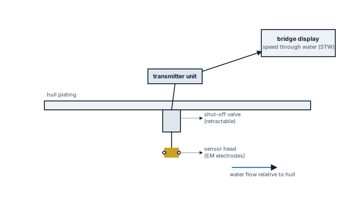
Electromagnetic speed log, hull installation
Cross-section through the hull showing the retractable speed log sensor with its electrodes, the shut-off valve, the transmitter unit and the bridge display reading speed through water.

Main components and types

Electromagnetic log

A sensor probe protrudes slightly through the hull and measures the small voltage induced as water flows past it, giving speed through water on the fore-aft axis and, on dual-axis units, athwartship speed as well, which matters during berthing on larger ships.

Doppler log

An acoustic transducer sends a signal toward the seabed and measures the frequency shift of the return, giving speed over ground while the seabed is within range, typically up to a few hundred metres of water depth; beyond that range it reverts to measuring against a water layer instead, giving speed through water without always making the switch obvious to the user.

Sensor housing

Many logs use a retractable housing so the sensor can be withdrawn for cleaning or inspection without dry-docking the ship, sealed by a valve when retracted.

Selection and sizing

  • Single-axis logs cover fore-aft speed only; dual-axis logs add transverse speed, useful for ships that need close manoeuvring data during berthing.
  • Doppler bottom-tracking range against the ship's typical operating depths, since deep-water passages rely on water-track mode instead.
  • Retractable versus fixed sensor housing, weighed against maintenance access and the hull maintenance schedule.

Regulations and class

SOLAS Chapter V requires ships above a certain size on international voyages to carry a speed and distance measuring device, and IMO performance standards set accuracy requirements for it. Class surveys check the transducer seacock or valve for watertight integrity, since it is a hull penetration below the waterline.

Typical faults

FaultCauseConsequence
Sensor foulingMarine growth on the electromagnetic sensor faceReading drifts and typically underreads actual speed
Bottom-lock lossDoppler log operating in water too deep for seabed returnSilent switch to water-track mode, speed over ground accuracy lost without a clear warning
Retraction mechanism seizureCorrosion or lack of exercise of the housingSensor cannot be withdrawn for maintenance, forcing a dry-dock delay
Calibration biasHull cleaning or repainting changing flow characteristics at the sensorSystematic speed error across the whole operating range

What to look for in a supplier

  • Transducer material and coating compatible with the ship's hull coating regime.
  • Reliability record of the retractable housing mechanism.
  • Calibration support after installation, hull cleaning, or dry-docking.
  • Standard data output, typically NMEA, compatible with the existing bridge systems.

GPS speed over ground looking correct on the display is not proof the log is working — through-water speed is what manoeuvring and squat calculations actually rely on, and only the log measures it independently of current.

14 manufacturers · 72 models

Furuno

11
DS-80 unverified
Type
Doppler Speed Log
Accuracy knots
0.1
IMO Compliant
ja
Common Failures & Inspection Points
  • Sensor or transmitter failure caused by electronics, RF, antenna or transducer faults, noticed as missing or degraded navigation data
  • External sensor-input failure caused by GNSS, heading, speed or network faults, noticed as alarms, frozen data or misaligned overlays
  • Display/processor failure caused by power, cooling, storage or software faults, noticed as blank screen, rebooting or unavailable functions
  • Antenna/transducer/cable damage caused by weather, water ingress, fouling or impact, noticed as weak, intermittent or implausible signals
  • Incorrect configuration or calibration caused by maintenance or operator error, noticed as persistent disagreement with independent references
Service: Verify the equipment against an independent navigation reference where practicable, inspect antennas/transducers, cables and power supplies, and confirm required sensor inputs and alarms. Check data distribution to dependent bridge equipment and review calibration, chart or configuration status appropriate to the device. Use vessel procedures and manufacturer tests for acceptance.
Spare Parts: Carry fuses, connectors, selected power-supply and cooling parts, interface converters and manufacturer-recommended display/processor or sensor spares. Hull-mounted sensor replacement should be planned around the actual access arrangement.
Use Cases: Used on bridge navigation systems of merchant, passenger, offshore and specialist vessels for position, heading, speed, depth, radar target information or electronic chart navigation.
DS-830 unverified
Type
Doppler Speed Log
Accuracy knots
0.1
IMO Compliant
ja
Common Failures & Inspection Points
  • Sensor or transmitter failure caused by electronics, RF, antenna or transducer faults, noticed as missing or degraded navigation data
  • External sensor-input failure caused by GNSS, heading, speed or network faults, noticed as alarms, frozen data or misaligned overlays
  • Display/processor failure caused by power, cooling, storage or software faults, noticed as blank screen, rebooting or unavailable functions
  • Antenna/transducer/cable damage caused by weather, water ingress, fouling or impact, noticed as weak, intermittent or implausible signals
  • Incorrect configuration or calibration caused by maintenance or operator error, noticed as persistent disagreement with independent references
Service: Verify the equipment against an independent navigation reference where practicable, inspect antennas/transducers, cables and power supplies, and confirm required sensor inputs and alarms. Check data distribution to dependent bridge equipment and review calibration, chart or configuration status appropriate to the device. Use vessel procedures and manufacturer tests for acceptance.
Spare Parts: Carry fuses, connectors, selected power-supply and cooling parts, interface converters and manufacturer-recommended display/processor or sensor spares. Hull-mounted sensor replacement should be planned around the actual access arrangement.
Use Cases: Used on bridge navigation systems of merchant, passenger, offshore and specialist vessels for position, heading, speed, depth, radar target information or electronic chart navigation.
DS-860 unverified
Type
Doppler Speed Log
Accuracy knots
0.1
IMO Compliant
ja
Common Failures & Inspection Points
  • Sensor or transmitter failure caused by electronics, RF, antenna or transducer faults, noticed as missing or degraded navigation data
  • External sensor-input failure caused by GNSS, heading, speed or network faults, noticed as alarms, frozen data or misaligned overlays
  • Display/processor failure caused by power, cooling, storage or software faults, noticed as blank screen, rebooting or unavailable functions
  • Antenna/transducer/cable damage caused by weather, water ingress, fouling or impact, noticed as weak, intermittent or implausible signals
  • Incorrect configuration or calibration caused by maintenance or operator error, noticed as persistent disagreement with independent references
Service: Verify the equipment against an independent navigation reference where practicable, inspect antennas/transducers, cables and power supplies, and confirm required sensor inputs and alarms. Check data distribution to dependent bridge equipment and review calibration, chart or configuration status appropriate to the device. Use vessel procedures and manufacturer tests for acceptance.
Spare Parts: Carry fuses, connectors, selected power-supply and cooling parts, interface converters and manufacturer-recommended display/processor or sensor spares. Hull-mounted sensor replacement should be planned around the actual access arrangement.
Use Cases: Used on bridge navigation systems of merchant, passenger, offshore and specialist vessels for position, heading, speed, depth, radar target information or electronic chart navigation.
DS-860 Compact unverified
Variant
Compact
IMO Compliant
ja
Common Failures & Inspection Points
  • Loss of sensor input or damaged cabling causes missing, frozen or implausible navigation data
  • Antenna, transducer or scanner faults reduce detection or measurement performance and generate equipment alarms
  • Power-supply or cooling faults cause resets, blank displays or complete loss of function
  • Configuration or interface faults cause disagreement between systems or missing data on connected equipment
  • Display, control or processing faults cause unstable operation, error messages or inability to select required functions
Service: Check power supplies, data interfaces, alarms, sensor health and agreement with independent navigation information where practical. Inspect external antennas, scanners or transducers as applicable and review fault logs and self-test results. Verify required backups, records and bridge procedures; exact calibration tolerances and test methods must follow manufacturer and statutory documentation.
Spare Parts: Typical spares include approved fuses, cooling fans, display or keypad parts where supported, interface modules, data cables and selected sensor or antenna components according to the vessel's critical-spares policy.
Use Cases: Used on commercial and offshore vessels for navigation, collision avoidance, route monitoring, heading control and voyage recording according to the specific equipment type.
DS-860 Standard unverified
Variant
Standard
IMO Compliant
ja
Common Failures & Inspection Points
  • Loss of sensor input or damaged cabling causes missing, frozen or implausible navigation data
  • Antenna, transducer or scanner faults reduce detection or measurement performance and generate equipment alarms
  • Power-supply or cooling faults cause resets, blank displays or complete loss of function
  • Configuration or interface faults cause disagreement between systems or missing data on connected equipment
  • Display, control or processing faults cause unstable operation, error messages or inability to select required functions
Service: Check power supplies, data interfaces, alarms, sensor health and agreement with independent navigation information where practical. Inspect external antennas, scanners or transducers as applicable and review fault logs and self-test results. Verify required backups, records and bridge procedures; exact calibration tolerances and test methods must follow manufacturer and statutory documentation.
Spare Parts: Typical spares include approved fuses, cooling fans, display or keypad parts where supported, interface modules, data cables and selected sensor or antenna components according to the vessel's critical-spares policy.
Use Cases: Used on commercial and offshore vessels for navigation, collision avoidance, route monitoring, heading control and voyage recording according to the specific equipment type.
DS-860 Heavy-Duty unverified
Variant
Heavy-Duty
IMO Compliant
ja
Common Failures & Inspection Points
  • Sensor, antenna or transducer fouling, damage or misalignment causes unstable, missing or inaccurate data
  • Power-supply or processor faults cause resets, blank displays or complete loss of indication
  • Cable, connector or network faults cause intermittent data or loss of outputs to other bridge systems
  • Incorrect configuration or calibration causes persistent disagreement with independent references
  • Display or software faults cause frozen values, alarms or unavailable functions
Service: Inspect sensors, antennas, transducers, cabling, power supplies, displays and data interfaces. Compare information with independent references and review alarm history. Verify distribution to dependent bridge systems. Refer to the manufacturer documentation for the exact figure for calibration, alignment and performance criteria.
Spare Parts: Carry fuses, interface cables, approved power supplies, sensor or antenna parts and supported display or processor modules.
Use Cases: Navigation, pilotage, collision avoidance and bridge-system integration.
DS-80 Mk2 unverified
IMO Compliant
ja
Common Failures & Inspection Points
  • Loss of electrical, hydraulic, pneumatic, or other service supply caused by a tripped protection device, leakage, blockage, or upstream fault results in failed starting or loss of function
  • Mechanical wear, corrosion, fouling, or contamination of moving and wetted parts causes increased noise, leakage, sticking, vibration, or reduced performance
  • Seal, gasket, hose, cable, or connection deterioration from age, heat, vibration, or environmental exposure produces visible leakage, intermittent signals, or loss of pressure
  • Sensor, switch, actuator, relay, or control-system faults can cause incorrect indication, nuisance alarms, failed automatic sequences, or loss of remote control
  • Incorrect adjustment, assembly, or maintenance can lead to unstable operation, recurrent alarms, or performance that differs from the vessel's normal baseline
Service: Inspect the unit for leakage, corrosion, contamination, loose connections, abnormal noise or vibration, condition of guards and mountings, service supplies, controls, alarms, and functional performance. Use the vessel maintenance history to identify deterioration trends and refer to the manufacturer documentation for exact settings, tolerances, test values, and overhaul criteria.
Spare Parts: Keep the manufacturer-recommended seals and gaskets, filters where fitted, fuses or protection items, common sensors and switches, and critical actuator, control, or wear components appropriate to the installed configuration. Exact part numbers and quantities must come from the manufacturer spare-parts documentation.
Use Cases: Used on vessel types fitted with position & heading equipment, including merchant, offshore, passenger, fishing, or workboat installations where this specific speed log duty is required.
DS-86 Mk2 unverified
IMO Compliant
ja
Common Failures & Inspection Points
  • Loss of electrical, hydraulic, pneumatic, or other service supply caused by a tripped protection device, leakage, blockage, or upstream fault results in failed starting or loss of function
  • Mechanical wear, corrosion, fouling, or contamination of moving and wetted parts causes increased noise, leakage, sticking, vibration, or reduced performance
  • Seal, gasket, hose, cable, or connection deterioration from age, heat, vibration, or environmental exposure produces visible leakage, intermittent signals, or loss of pressure
  • Sensor, switch, actuator, relay, or control-system faults can cause incorrect indication, nuisance alarms, failed automatic sequences, or loss of remote control
  • Incorrect adjustment, assembly, or maintenance can lead to unstable operation, recurrent alarms, or performance that differs from the vessel's normal baseline
Service: Inspect the unit for leakage, corrosion, contamination, loose connections, abnormal noise or vibration, condition of guards and mountings, service supplies, controls, alarms, and functional performance. Use the vessel maintenance history to identify deterioration trends and refer to the manufacturer documentation for exact settings, tolerances, test values, and overhaul criteria.
Spare Parts: Keep the manufacturer-recommended seals and gaskets, filters where fitted, fuses or protection items, common sensors and switches, and critical actuator, control, or wear components appropriate to the installed configuration. Exact part numbers and quantities must come from the manufacturer spare-parts documentation.
Use Cases: Used on vessel types fitted with position & heading equipment, including merchant, offshore, passenger, fishing, or workboat installations where this specific speed log duty is required.
DS-880 SDME unverified
IMO Compliant
ja
Common Failures & Inspection Points
  • Sensor fouling caused by marine growth, paint or debris, resulting in low or unstable speed indication
  • Transducer or cabling fault caused by water ingress or electrical damage, resulting in loss of speed data
  • Calibration drift caused by sensor aging or installation changes, resulting in persistent disagreement with expected speed
  • Processor or display failure caused by power or electronics faults, resulting in blank or frozen indication
  • Interface failure caused by network or serial-data faults, resulting in missing speed input at radar, ECDIS or other systems
Service: Compare the indicated value with independent references and investigate persistent disagreement rather than applying unrecorded corrections. Inspect sensors, antennas, cabling, power supplies, repeaters and network interfaces applicable to the installed equipment. Verify alarms and data outputs to radar, ECDIS, autopilot and voyage-data systems where connected. Keep calibration, deviation or configuration records current as appropriate to the sensor type. Protect exposed sensors from paint, deposits and water ingress. Refer to manufacturer and bridge-equipment documentation for exact test, calibration and alignment procedures.
Spare Parts: Keep fuses, lamps or display consumables, selected power-supply and interface modules, cables or connectors and manufacturer-recommended sensor service parts. Replacement core sensors or processors must remain compatible with the approved bridge installation. Preserve calibration and configuration data when changing equipment.
Use Cases: Heading, position or speed information for navigation, collision avoidance, autopilot, ECDIS and other bridge systems on merchant and offshore vessels.
DS-890 SDME unverified
IMO Compliant
ja
Common Failures & Inspection Points
  • Sensor fouling caused by marine growth, paint or debris, resulting in low or unstable speed indication
  • Transducer or cabling fault caused by water ingress or electrical damage, resulting in loss of speed data
  • Calibration drift caused by sensor aging or installation changes, resulting in persistent disagreement with expected speed
  • Processor or display failure caused by power or electronics faults, resulting in blank or frozen indication
  • Interface failure caused by network or serial-data faults, resulting in missing speed input at radar, ECDIS or other systems
Service: Compare the indicated value with independent references and investigate persistent disagreement rather than applying unrecorded corrections. Inspect sensors, antennas, cabling, power supplies, repeaters and network interfaces applicable to the installed equipment. Verify alarms and data outputs to radar, ECDIS, autopilot and voyage-data systems where connected. Keep calibration, deviation or configuration records current as appropriate to the sensor type. Protect exposed sensors from paint, deposits and water ingress. Refer to manufacturer and bridge-equipment documentation for exact test, calibration and alignment procedures.
Spare Parts: Keep fuses, lamps or display consumables, selected power-supply and interface modules, cables or connectors and manufacturer-recommended sensor service parts. Replacement core sensors or processors must remain compatible with the approved bridge installation. Preserve calibration and configuration data when changing equipment.
Use Cases: Heading, position or speed information for navigation, collision avoidance, autopilot, ECDIS and other bridge systems on merchant and offshore vessels.
DS-830 EM unverified
IMO Compliant
ja
Common Failures & Inspection Points
  • Loss of electrical, hydraulic, pneumatic, or other service supply caused by a tripped protection device, leakage, blockage, or upstream fault results in failed starting or loss of function
  • Mechanical wear, corrosion, fouling, or contamination of moving and wetted parts causes increased noise, leakage, sticking, vibration, or reduced performance
  • Seal, gasket, hose, cable, or connection deterioration from age, heat, vibration, or environmental exposure produces visible leakage, intermittent signals, or loss of pressure
  • Sensor, switch, actuator, relay, or control-system faults can cause incorrect indication, nuisance alarms, failed automatic sequences, or loss of remote control
  • Incorrect adjustment, assembly, or maintenance can lead to unstable operation, recurrent alarms, or performance that differs from the vessel's normal baseline
Service: Inspect the unit for leakage, corrosion, contamination, loose connections, abnormal noise or vibration, condition of guards and mountings, service supplies, controls, alarms, and functional performance. Use the vessel maintenance history to identify deterioration trends and refer to the manufacturer documentation for exact settings, tolerances, test values, and overhaul criteria.
Spare Parts: Keep the manufacturer-recommended seals and gaskets, filters where fitted, fuses or protection items, common sensors and switches, and critical actuator, control, or wear components appropriate to the installed configuration. Exact part numbers and quantities must come from the manufacturer spare-parts documentation.
Use Cases: Used on vessel types fitted with position & heading equipment, including merchant, offshore, passenger, fishing, or workboat installations where this specific speed log duty is required.

Raytheon Anschütz

9
NautoPilot Speed
EM/Doppler · Navigation Data / Sensor · EM/Doppler speed log
Technology
EM/Doppler
Common Failures & Inspection Points
  • Sensor, antenna or transducer fouling, damage or misalignment causes unstable, missing or inaccurate data
  • Power-supply or processor faults cause resets, blank displays or complete loss of indication
  • Cable, connector or network faults cause intermittent data or loss of outputs to dependent bridge systems
  • Incorrect configuration or calibration causes persistent disagreement with independent references
  • Display, storage or software faults cause frozen values, alarms or unavailable navigation functions
Service: Inspect sensors, antennas, transducers, cabling, power supplies, displays and data interfaces. Compare information with independent references and review alarm history. Verify distribution to dependent bridge systems and confirm approved backup arrangements. Refer to the manufacturer documentation for the exact figure for calibration, alignment and performance criteria.
Spare Parts: Carry fuses, interface cables, approved power supplies, sensor or antenna parts and supported display or processor modules, together with backed-up configuration data where applicable.
Strengths
  • High accuracy with electromagnetic Doppler measurement, no moving parts to wear out
  • Seamless integration with Raytheon Anschütz autopilot for instant speed feedback
  • Low maintenance requirement compared with mechanical pitot tubes or paddle wheels
  • Proven reliability on vessels equipped with the full Raytheon autopilot suite
Weaknesses
  • Calibration is tied to the autopilot software, limiting independent use
  • Sensor performance can degrade over time (aging of EM transducers) requiring periodic recalibration
  • Standalone operation is limited; not ideal for ships using a different autopilot brand
  • Potential electromagnetic interference in heavily instrumented bridge areas
Typical Vessels: Container shipTankerBulk carrierCruise linerOffshore supply vessel
Decision Guide: Choose if the vessel already uses Raytheon Anschütz autopilot and requires a tightly coupled, high‑accuracy speed source for steering or DP functions. Avoid if you need an independent speed log that can be swapped between different bridge systems or if long‑term standalone reliability without frequent recalibration is a priority.
Use Cases: Navigation, pilotage, collision avoidance and bridge-system integration.
Raytheon Anschütz NautoSpeed Log
NautoSpeed Log unverified
Type
Doppler
IMO Compliant
ja
Common Failures & Inspection Points
  • Sensor or antenna degradation caused by contamination, damage, ageing or poor exposure can produce missing, unstable or implausible data
  • Connector, cable or network faults caused by vibration, corrosion or disturbed terminations can cause intermittent data loss or interface alarms
  • Power-supply or internal electronics failure caused by ageing, heat or poor ventilation can result in resets, blank indications or complete loss of function
  • Configuration or software errors after service or replacement can cause incorrect data, rejected inputs or loss of communication with other bridge equipment
  • Mechanical damage or water ingress at exposed components can lead to erratic readings, repeated alarms or loss of the affected channel
Service: Inspect exposed sensors or antennas, cable routes, connectors, power supplies, displays and network interfaces. Confirm that indicated or recorded data is plausible and that built-in tests and alarms operate. Compare configuration and test results with the vessel's approved records and manufacturer documentation.
Spare Parts: Keep maker-recommended fuses, connectors, sensor accessories, fans, interface or power modules and other approved line-replaceable items that match the installed configuration.
Use Cases: Commercial ships, passenger vessels, offshore vessels and workboats requiring bridge navigation, recording, environmental or traffic information.
Doppler Speed Log DSL-200 unverified
Type
Doppler
IMO Compliant
ja
Common Failures & Inspection Points
  • Sensor or gyro fault caused by wear, fouling, damage or electronics failure, resulting in lost, unstable or inaccurate navigation data
  • Power-supply failure caused by breaker, converter or wiring problems, resulting in loss of indication
  • Processor or display fault caused by electronics or software problems, resulting in frozen, blank or erroneous output
  • Interface or network failure caused by cabling or configuration faults, resulting in missing data at connected bridge equipment
  • Calibration, alignment or configuration error caused by incorrect setup or maintenance, resulting in persistent disagreement with independent references
Service: Compare the indicated value with independent references and investigate persistent disagreement rather than applying unrecorded corrections. Inspect sensors, cabling, power supplies, repeaters and network interfaces applicable to the installed equipment. Verify alarms and data outputs to radar, ECDIS, autopilot and voyage-data systems where connected. Keep calibration or configuration records current as appropriate to the sensor type. Protect exposed sensors from paint, deposits and water ingress. Refer to the manufacturer documentation for the exact figure for test, calibration and alignment procedures.
Spare Parts: Keep fuses, display consumables, selected power-supply and interface modules, cables or connectors and manufacturer-recommended sensor service parts. Replacement core sensors or processors must remain compatible with the approved bridge installation. Preserve calibration and configuration data when changing equipment.
Use Cases: Heading or speed information for navigation, collision avoidance, autopilot, ECDIS and other bridge systems.
Raytheon Anschütz DSL-300
DSL-300 unverified
Type
Doppler
IMO Compliant
ja
Common Failures & Inspection Points
  • Loss of electrical, hydraulic, pneumatic, or other service supply caused by a tripped protection device, leakage, blockage, or upstream fault results in failed starting or loss of function
  • Mechanical wear, corrosion, fouling, or contamination of moving and wetted parts causes increased noise, leakage, sticking, vibration, or reduced performance
  • Seal, gasket, hose, cable, or connection deterioration from age, heat, vibration, or environmental exposure produces visible leakage, intermittent signals, or loss of pressure
  • Sensor, switch, actuator, relay, or control-system faults can cause incorrect indication, nuisance alarms, failed automatic sequences, or loss of remote control
  • Incorrect adjustment, assembly, or maintenance can lead to unstable operation, recurrent alarms, or performance that differs from the vessel's normal baseline
Service: Inspect the unit for leakage, corrosion, contamination, loose connections, abnormal noise or vibration, condition of guards and mountings, service supplies, controls, alarms, and functional performance. Use the vessel maintenance history to identify deterioration trends and refer to the manufacturer documentation for exact settings, tolerances, test values, and overhaul criteria.
Spare Parts: Keep the manufacturer-recommended seals and gaskets, filters where fitted, fuses or protection items, common sensors and switches, and critical actuator, control, or wear components appropriate to the installed configuration. Exact part numbers and quantities must come from the manufacturer spare-parts documentation.
Use Cases: Used on vessel types fitted with position & heading equipment, including merchant, offshore, passenger, fishing, or workboat installations where this specific speed log duty is required.
Raytheon Anschütz NautoSpeed 200
NautoSpeed 200 unverified
IMO Compliant
ja
Common Failures & Inspection Points
  • Sensor or antenna degradation caused by contamination, damage, ageing or poor exposure can produce missing, unstable or implausible data
  • Connector, cable or network faults caused by vibration, corrosion or disturbed terminations can cause intermittent data loss or interface alarms
  • Power-supply or internal electronics failure caused by ageing, heat or poor ventilation can result in resets, blank indications or complete loss of function
  • Configuration or software errors after service or replacement can cause incorrect data, rejected inputs or loss of communication with other bridge equipment
  • Mechanical damage or water ingress at exposed components can lead to erratic readings, repeated alarms or loss of the affected channel
Service: Inspect exposed sensors or antennas, cable routes, connectors, power supplies, displays and network interfaces. Confirm that indicated or recorded data is plausible and that built-in tests and alarms operate. Compare configuration and test results with the vessel's approved records and manufacturer documentation.
Spare Parts: Keep maker-recommended fuses, connectors, sensor accessories, fans, interface or power modules and other approved line-replaceable items that match the installed configuration.
Use Cases: Commercial ships, passenger vessels, offshore vessels and workboats requiring bridge navigation, recording, environmental or traffic information.
NautoSpeed 300 unverified
IMO Compliant
ja
Common Failures & Inspection Points
  • Sensor or antenna degradation caused by contamination, damage, ageing or poor exposure can produce missing, unstable or implausible data
  • Connector, cable or network faults caused by vibration, corrosion or disturbed terminations can cause intermittent data loss or interface alarms
  • Power-supply or internal electronics failure caused by ageing, heat or poor ventilation can result in resets, blank indications or complete loss of function
  • Configuration or software errors after service or replacement can cause incorrect data, rejected inputs or loss of communication with other bridge equipment
  • Mechanical damage or water ingress at exposed components can lead to erratic readings, repeated alarms or loss of the affected channel
Service: Inspect exposed sensors or antennas, cable routes, connectors, power supplies, displays and network interfaces. Confirm that indicated or recorded data is plausible and that built-in tests and alarms operate. Compare configuration and test results with the vessel's approved records and manufacturer documentation.
Spare Parts: Keep maker-recommended fuses, connectors, sensor accessories, fans, interface or power modules and other approved line-replaceable items that match the installed configuration.
Use Cases: Commercial ships, passenger vessels, offshore vessels and workboats requiring bridge navigation, recording, environmental or traffic information.
Raytheon Anschütz NautoSpeed 400
NautoSpeed 400 unverified
IMO Compliant
ja
Common Failures & Inspection Points
  • Sensor or antenna degradation caused by contamination, damage, ageing or poor exposure can produce missing, unstable or implausible data
  • Connector, cable or network faults caused by vibration, corrosion or disturbed terminations can cause intermittent data loss or interface alarms
  • Power-supply or internal electronics failure caused by ageing, heat or poor ventilation can result in resets, blank indications or complete loss of function
  • Configuration or software errors after service or replacement can cause incorrect data, rejected inputs or loss of communication with other bridge equipment
  • Mechanical damage or water ingress at exposed components can lead to erratic readings, repeated alarms or loss of the affected channel
Service: Inspect exposed sensors or antennas, cable routes, connectors, power supplies, displays and network interfaces. Confirm that indicated or recorded data is plausible and that built-in tests and alarms operate. Compare configuration and test results with the vessel's approved records and manufacturer documentation.
Spare Parts: Keep maker-recommended fuses, connectors, sensor accessories, fans, interface or power modules and other approved line-replaceable items that match the installed configuration.
Use Cases: Commercial ships, passenger vessels, offshore vessels and workboats requiring bridge navigation, recording, environmental or traffic information.
DSL-400 unverified
IMO Compliant
ja
Common Failures & Inspection Points
  • Loss of electrical, hydraulic, pneumatic, or other service supply caused by a tripped protection device, leakage, blockage, or upstream fault results in failed starting or loss of function
  • Mechanical wear, corrosion, fouling, or contamination of moving and wetted parts causes increased noise, leakage, sticking, vibration, or reduced performance
  • Seal, gasket, hose, cable, or connection deterioration from age, heat, vibration, or environmental exposure produces visible leakage, intermittent signals, or loss of pressure
  • Sensor, switch, actuator, relay, or control-system faults can cause incorrect indication, nuisance alarms, failed automatic sequences, or loss of remote control
  • Incorrect adjustment, assembly, or maintenance can lead to unstable operation, recurrent alarms, or performance that differs from the vessel's normal baseline
Service: Inspect the unit for leakage, corrosion, contamination, loose connections, abnormal noise or vibration, condition of guards and mountings, service supplies, controls, alarms, and functional performance. Use the vessel maintenance history to identify deterioration trends and refer to the manufacturer documentation for exact settings, tolerances, test values, and overhaul criteria.
Spare Parts: Keep the manufacturer-recommended seals and gaskets, filters where fitted, fuses or protection items, common sensors and switches, and critical actuator, control, or wear components appropriate to the installed configuration. Exact part numbers and quantities must come from the manufacturer spare-parts documentation.
Use Cases: Used on vessel types fitted with position & heading equipment, including merchant, offshore, passenger, fishing, or workboat installations where this specific speed log duty is required.
DSL-500 unverified
IMO Compliant
ja
Common Failures & Inspection Points
  • Loss of electrical, hydraulic, pneumatic, or other service supply caused by a tripped protection device, leakage, blockage, or upstream fault results in failed starting or loss of function
  • Mechanical wear, corrosion, fouling, or contamination of moving and wetted parts causes increased noise, leakage, sticking, vibration, or reduced performance
  • Seal, gasket, hose, cable, or connection deterioration from age, heat, vibration, or environmental exposure produces visible leakage, intermittent signals, or loss of pressure
  • Sensor, switch, actuator, relay, or control-system faults can cause incorrect indication, nuisance alarms, failed automatic sequences, or loss of remote control
  • Incorrect adjustment, assembly, or maintenance can lead to unstable operation, recurrent alarms, or performance that differs from the vessel's normal baseline
Service: Inspect the unit for leakage, corrosion, contamination, loose connections, abnormal noise or vibration, condition of guards and mountings, service supplies, controls, alarms, and functional performance. Use the vessel maintenance history to identify deterioration trends and refer to the manufacturer documentation for exact settings, tolerances, test values, and overhaul criteria.
Spare Parts: Keep the manufacturer-recommended seals and gaskets, filters where fitted, fuses or protection items, common sensors and switches, and critical actuator, control, or wear components appropriate to the installed configuration. Exact part numbers and quantities must come from the manufacturer spare-parts documentation.
Use Cases: Used on vessel types fitted with position & heading equipment, including merchant, offshore, passenger, fishing, or workboat installations where this specific speed log duty is required.

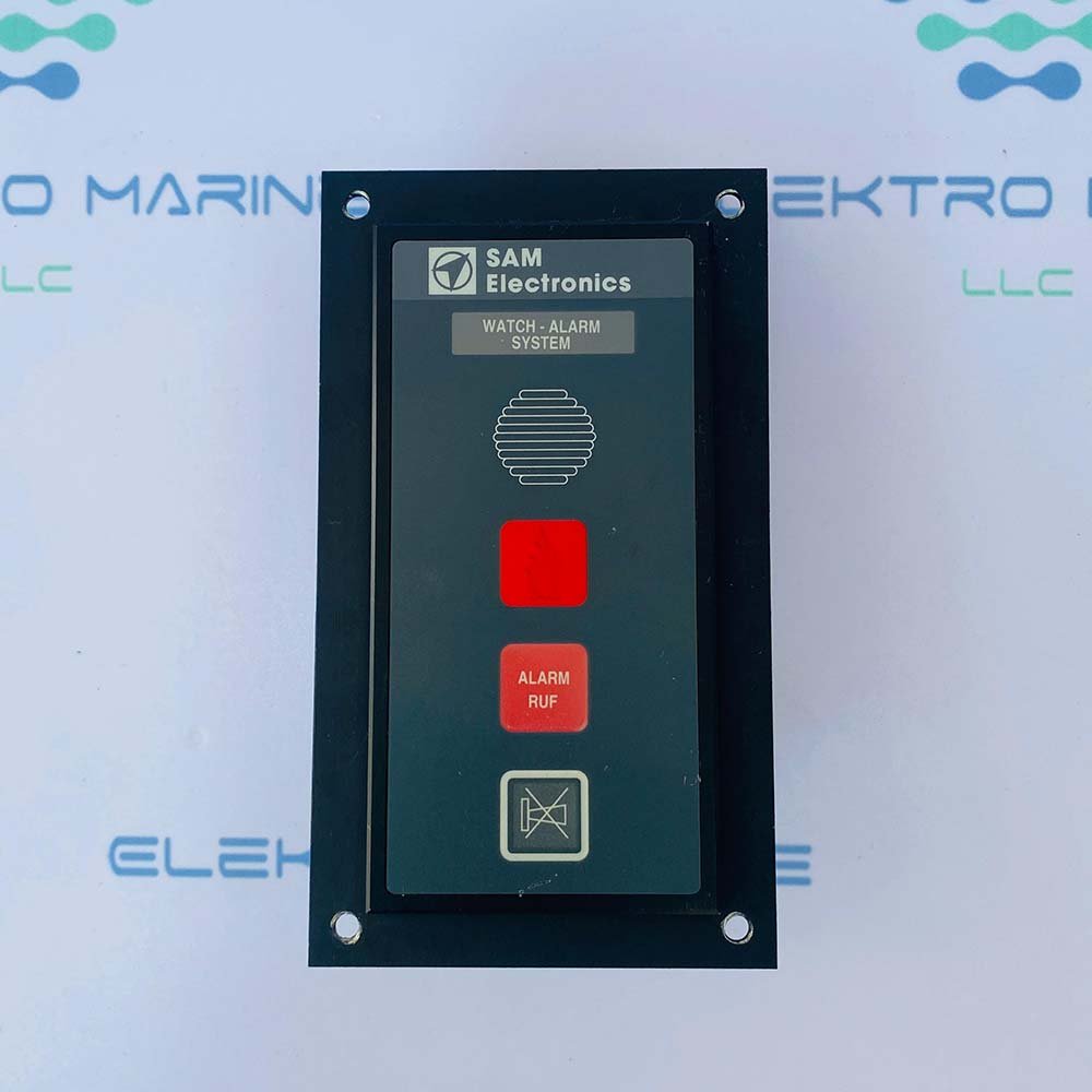
SAM Electronics

8
SAM Electronics EM Log SAM
EM Log SAM
EM Log · Navigation Data / Sensor · electromagnetic speed log
Technology
Electromagnetic
Common Failures & Inspection Points
  • Sensor, antenna or transducer fouling, damage or misalignment causes unstable, missing or inaccurate data
  • Power-supply or processor faults cause resets, blank displays or complete loss of indication
  • Cable, connector or network faults cause intermittent data or loss of outputs to dependent bridge systems
  • Incorrect configuration or calibration causes persistent disagreement with independent references
  • Display, storage or software faults cause frozen values, alarms or unavailable navigation functions
Service: Inspect sensors, antennas, transducers, cabling, power supplies, displays and data interfaces. Compare information with independent references and review alarm history. Verify distribution to dependent bridge systems and confirm approved backup arrangements. Refer to the manufacturer documentation for the exact figure for calibration, alignment and performance criteria.
Spare Parts: Carry fuses, interface cables, approved power supplies, sensor or antenna parts and supported display or processor modules, together with backed-up configuration data where applicable.
Strengths
  • No rotating components – virtually zero mechanical wear and low maintenance
  • High measurement accuracy (±0.1 kn) across a wide speed range
  • Fast response time suitable for dynamic positioning and fuel‑efficiency monitoring
  • Compact installation on hull with minimal protrusion
  • Integrated data output compatible with common bridge consoles
Weaknesses
  • Performance degrades in low‑conductivity water (e.g., fresh or brackish water)
  • Sensitive to hull fouling and magnetic interference from nearby equipment
  • Requires periodic calibration; loss of calibration data has been reported on legacy units
  • Limited redundancy – many operators pair it with a mechanical log for safety
Typical Vessels: Bulk CarrierTankerContainer ShipCruise VesselOffshore Support Vessel
Decision Guide: Choose if you need high‑accuracy speed data, low maintenance, and integration with modern bridge systems. Avoid if the vessel operates primarily in fresh water, requires multiple independent speed sources, or cannot accommodate periodic calibration procedures.
Use Cases: Navigation, pilotage, collision avoidance and bridge-system integration.
SAL-860 unverified
Type
Acoustic Correlation
IMO Compliant
ja
Common Failures & Inspection Points
  • Sensor or antenna fault caused by fouling, damage, wear or water ingress, resulting in loss, weak response or degraded navigation data
  • Power-supply failure caused by breaker, converter or wiring problems, resulting in loss of indication
  • Processor or display fault caused by electronics or software problems, resulting in frozen, blank or erroneous output
  • Interface or network failure caused by cabling or configuration faults, resulting in missing data at connected bridge equipment
  • Calibration, alignment or configuration error caused by incorrect setup or maintenance, resulting in persistent disagreement with independent navigation references
Service: Compare the indicated value with independent references and investigate persistent disagreement rather than applying unrecorded corrections. Inspect sensors, antennas, transducers, cabling, power supplies, repeaters and network interfaces applicable to the installed equipment. Verify alarms and data outputs to radar, ECDIS, autopilot and voyage-data systems where connected. Keep calibration, deviation or configuration records current as appropriate to the sensor type. Protect exposed sensors and transducers from paint, deposits and water ingress. Refer to manufacturer and bridge-equipment documentation for exact test, calibration and alignment procedures.
Spare Parts: Keep fuses, lamps or display consumables, selected power-supply and interface modules, cables or connectors and manufacturer-recommended sensor service parts. Replacement core sensors, antennas or processors must remain compatible with the approved bridge installation. Preserve calibration and configuration data when changing equipment.
Use Cases: Bridge navigation and sensor input for collision avoidance, route monitoring, steering, depth awareness and other shipboard navigation functions according to the equipment category.
SAL-870 unverified
Type
Acoustic Correlation
IMO Compliant
ja
Common Failures & Inspection Points
  • Sensor or antenna fault caused by fouling, damage, wear or water ingress, resulting in loss, weak response or degraded navigation data
  • Power-supply failure caused by breaker, converter or wiring problems, resulting in loss of indication
  • Processor or display fault caused by electronics or software problems, resulting in frozen, blank or erroneous output
  • Interface or network failure caused by cabling or configuration faults, resulting in missing data at connected bridge equipment
  • Calibration, alignment or configuration error caused by incorrect setup or maintenance, resulting in persistent disagreement with independent navigation references
Service: Compare the indicated value with independent references and investigate persistent disagreement rather than applying unrecorded corrections. Inspect sensors, antennas, transducers, cabling, power supplies, repeaters and network interfaces applicable to the installed equipment. Verify alarms and data outputs to radar, ECDIS, autopilot and voyage-data systems where connected. Keep calibration, deviation or configuration records current as appropriate to the sensor type. Protect exposed sensors and transducers from paint, deposits and water ingress. Refer to manufacturer and bridge-equipment documentation for exact test, calibration and alignment procedures.
Spare Parts: Keep fuses, lamps or display consumables, selected power-supply and interface modules, cables or connectors and manufacturer-recommended sensor service parts. Replacement core sensors, antennas or processors must remain compatible with the approved bridge installation. Preserve calibration and configuration data when changing equipment.
Use Cases: Bridge navigation and sensor input for collision avoidance, route monitoring, steering, depth awareness and other shipboard navigation functions according to the equipment category.
SAL-880 unverified
Type
Acoustic Correlation
IMO Compliant
ja
Common Failures & Inspection Points
  • Sensor or antenna fault caused by fouling, damage, wear or water ingress, resulting in loss, weak response or degraded navigation data
  • Power-supply failure caused by breaker, converter or wiring problems, resulting in loss of indication
  • Processor or display fault caused by electronics or software problems, resulting in frozen, blank or erroneous output
  • Interface or network failure caused by cabling or configuration faults, resulting in missing data at connected bridge equipment
  • Calibration, alignment or configuration error caused by incorrect setup or maintenance, resulting in persistent disagreement with independent navigation references
Service: Compare the indicated value with independent references and investigate persistent disagreement rather than applying unrecorded corrections. Inspect sensors, antennas, transducers, cabling, power supplies, repeaters and network interfaces applicable to the installed equipment. Verify alarms and data outputs to radar, ECDIS, autopilot and voyage-data systems where connected. Keep calibration, deviation or configuration records current as appropriate to the sensor type. Protect exposed sensors and transducers from paint, deposits and water ingress. Refer to manufacturer and bridge-equipment documentation for exact test, calibration and alignment procedures.
Spare Parts: Keep fuses, lamps or display consumables, selected power-supply and interface modules, cables or connectors and manufacturer-recommended sensor service parts. Replacement core sensors, antennas or processors must remain compatible with the approved bridge installation. Preserve calibration and configuration data when changing equipment.
Use Cases: Bridge navigation and sensor input for collision avoidance, route monitoring, steering, depth awareness and other shipboard navigation functions according to the equipment category.
SAL-860 Mk2 unverified
IMO Compliant
ja
Common Failures & Inspection Points
  • Loss of electrical, hydraulic, pneumatic, or other service supply caused by a tripped protection device, leakage, blockage, or upstream fault results in failed starting or loss of function
  • Mechanical wear, corrosion, fouling, or contamination of moving and wetted parts causes increased noise, leakage, sticking, vibration, or reduced performance
  • Seal, gasket, hose, cable, or connection deterioration from age, heat, vibration, or environmental exposure produces visible leakage, intermittent signals, or loss of pressure
  • Sensor, switch, actuator, relay, or control-system faults can cause incorrect indication, nuisance alarms, failed automatic sequences, or loss of remote control
  • Incorrect adjustment, assembly, or maintenance can lead to unstable operation, recurrent alarms, or performance that differs from the vessel's normal baseline
Service: Inspect the unit for leakage, corrosion, contamination, loose connections, abnormal noise or vibration, condition of guards and mountings, service supplies, controls, alarms, and functional performance. Use the vessel maintenance history to identify deterioration trends and refer to the manufacturer documentation for exact settings, tolerances, test values, and overhaul criteria.
Spare Parts: Keep the manufacturer-recommended seals and gaskets, filters where fitted, fuses or protection items, common sensors and switches, and critical actuator, control, or wear components appropriate to the installed configuration. Exact part numbers and quantities must come from the manufacturer spare-parts documentation.
Use Cases: Used on vessel types fitted with position & heading equipment, including merchant, offshore, passenger, fishing, or workboat installations where this specific speed log duty is required.
SAL-870 Mk2 unverified
IMO Compliant
ja
Common Failures & Inspection Points
  • Loss of electrical, hydraulic, pneumatic, or other service supply caused by a tripped protection device, leakage, blockage, or upstream fault results in failed starting or loss of function
  • Mechanical wear, corrosion, fouling, or contamination of moving and wetted parts causes increased noise, leakage, sticking, vibration, or reduced performance
  • Seal, gasket, hose, cable, or connection deterioration from age, heat, vibration, or environmental exposure produces visible leakage, intermittent signals, or loss of pressure
  • Sensor, switch, actuator, relay, or control-system faults can cause incorrect indication, nuisance alarms, failed automatic sequences, or loss of remote control
  • Incorrect adjustment, assembly, or maintenance can lead to unstable operation, recurrent alarms, or performance that differs from the vessel's normal baseline
Service: Inspect the unit for leakage, corrosion, contamination, loose connections, abnormal noise or vibration, condition of guards and mountings, service supplies, controls, alarms, and functional performance. Use the vessel maintenance history to identify deterioration trends and refer to the manufacturer documentation for exact settings, tolerances, test values, and overhaul criteria.
Spare Parts: Keep the manufacturer-recommended seals and gaskets, filters where fitted, fuses or protection items, common sensors and switches, and critical actuator, control, or wear components appropriate to the installed configuration. Exact part numbers and quantities must come from the manufacturer spare-parts documentation.
Use Cases: Used on vessel types fitted with position & heading equipment, including merchant, offshore, passenger, fishing, or workboat installations where this specific speed log duty is required.
SAL-880 Mk2 unverified
IMO Compliant
ja
Common Failures & Inspection Points
  • Loss of electrical, hydraulic, pneumatic, or other service supply caused by a tripped protection device, leakage, blockage, or upstream fault results in failed starting or loss of function
  • Mechanical wear, corrosion, fouling, or contamination of moving and wetted parts causes increased noise, leakage, sticking, vibration, or reduced performance
  • Seal, gasket, hose, cable, or connection deterioration from age, heat, vibration, or environmental exposure produces visible leakage, intermittent signals, or loss of pressure
  • Sensor, switch, actuator, relay, or control-system faults can cause incorrect indication, nuisance alarms, failed automatic sequences, or loss of remote control
  • Incorrect adjustment, assembly, or maintenance can lead to unstable operation, recurrent alarms, or performance that differs from the vessel's normal baseline
Service: Inspect the unit for leakage, corrosion, contamination, loose connections, abnormal noise or vibration, condition of guards and mountings, service supplies, controls, alarms, and functional performance. Use the vessel maintenance history to identify deterioration trends and refer to the manufacturer documentation for exact settings, tolerances, test values, and overhaul criteria.
Spare Parts: Keep the manufacturer-recommended seals and gaskets, filters where fitted, fuses or protection items, common sensors and switches, and critical actuator, control, or wear components appropriate to the installed configuration. Exact part numbers and quantities must come from the manufacturer spare-parts documentation.
Use Cases: Used on vessel types fitted with position & heading equipment, including merchant, offshore, passenger, fishing, or workboat installations where this specific speed log duty is required.
SAL-890 unverified
IMO Compliant
ja
Common Failures & Inspection Points
  • Sensor or antenna fault caused by fouling, damage, wear or water ingress, resulting in loss, weak response or degraded navigation data
  • Power-supply failure caused by breaker, converter or wiring problems, resulting in loss of indication
  • Processor or display fault caused by electronics or software problems, resulting in frozen, blank or erroneous output
  • Interface or network failure caused by cabling or configuration faults, resulting in missing data at connected bridge equipment
  • Calibration, alignment or configuration error caused by incorrect setup or maintenance, resulting in persistent disagreement with independent navigation references
Service: Compare the indicated value with independent references and investigate persistent disagreement rather than applying unrecorded corrections. Inspect sensors, antennas, transducers, cabling, power supplies, repeaters and network interfaces applicable to the installed equipment. Verify alarms and data outputs to radar, ECDIS, autopilot and voyage-data systems where connected. Keep calibration, deviation or configuration records current as appropriate to the sensor type. Protect exposed sensors and transducers from paint, deposits and water ingress. Refer to manufacturer and bridge-equipment documentation for exact test, calibration and alignment procedures.
Spare Parts: Keep fuses, lamps or display consumables, selected power-supply and interface modules, cables or connectors and manufacturer-recommended sensor service parts. Replacement core sensors, antennas or processors must remain compatible with the approved bridge installation. Preserve calibration and configuration data when changing equipment.
Use Cases: Bridge navigation and sensor input for collision avoidance, route monitoring, steering, depth awareness and other shipboard navigation functions according to the equipment category.

Sperry Marine

8
Sperry Marine SRD-500
SRD-500
Doppler / dual-axis · Navigation Data / Sensor · Doppler speed log
Technology
Doppler
IMO Approved
ja
Common Failures & Inspection Points
  • Sensor, antenna or transducer fouling, damage or misalignment causes unstable, missing or inaccurate data
  • Power-supply or processor faults cause resets, blank displays or complete loss of indication
  • Cable, connector or network faults cause intermittent data or loss of outputs to dependent bridge systems
  • Incorrect configuration or calibration causes persistent disagreement with independent references
  • Display, storage or software faults cause frozen values, alarms or unavailable navigation functions
Service: Inspect sensors, antennas, transducers, cabling, power supplies, displays and data interfaces. Compare information with independent references and review alarm history. Verify distribution to dependent bridge systems and confirm approved backup arrangements. Refer to the manufacturer documentation for the exact figure for calibration, alignment and performance criteria.
Spare Parts: Carry fuses, interface cables, approved power supplies, sensor or antenna parts and supported display or processor modules, together with backed-up configuration data where applicable.
Strengths
  • High accuracy Doppler measurement suitable for performance monitoring
  • Full standalone operation when VisionMaster integration is not used
  • IMO type‑approved, meeting international navigation standards
  • Designed specifically for seamless integration with Sperry Marine bridge consoles
  • Robust transducer construction for long‑term marine service
Weaknesses
  • Optimal functionality relies on VisionMaster integration; limited features on other bridges
  • Known gate‑valve wear in the transducer can require periodic maintenance
  • Calibration procedures are complex and often need specialist support
  • Spare parts and service expertise are primarily tied to Sperry Marine networks
  • Higher initial cost compared with basic mechanical logs
Typical Vessels: TankerContainer shipBulk carrierCruise linerOffshore support vessel
Certifications: IMO Type Approval
Decision Guide: Choose if the vessel already uses Sperry Marine bridge equipment, requires high‑precision speed data for navigation or fuel performance, and can accommodate regular calibration. Avoid if the ship operates with a non‑Sperry bridge suite, has limited maintenance resources, or seeks a low‑cost, simple mechanical log.
Use Cases: Navigation, pilotage, collision avoidance and bridge-system integration.
Naviknot III unverified
Type
Doppler
IMO Compliant
ja
Common Failures & Inspection Points
  • Loss of electrical, hydraulic, pneumatic, or other service supply caused by a tripped protection device, leakage, blockage, or upstream fault results in failed starting or loss of function
  • Mechanical wear, corrosion, fouling, or contamination of moving and wetted parts causes increased noise, leakage, sticking, vibration, or reduced performance
  • Seal, gasket, hose, cable, or connection deterioration from age, heat, vibration, or environmental exposure produces visible leakage, intermittent signals, or loss of pressure
  • Sensor, switch, actuator, relay, or control-system faults can cause incorrect indication, nuisance alarms, failed automatic sequences, or loss of remote control
  • Incorrect adjustment, assembly, or maintenance can lead to unstable operation, recurrent alarms, or performance that differs from the vessel's normal baseline
Service: Inspect the unit for leakage, corrosion, contamination, loose connections, abnormal noise or vibration, condition of guards and mountings, service supplies, controls, alarms, and functional performance. Use the vessel maintenance history to identify deterioration trends and refer to the manufacturer documentation for exact settings, tolerances, test values, and overhaul criteria.
Spare Parts: Keep the manufacturer-recommended seals and gaskets, filters where fitted, fuses or protection items, common sensors and switches, and critical actuator, control, or wear components appropriate to the installed configuration. Exact part numbers and quantities must come from the manufacturer spare-parts documentation.
Use Cases: Used on vessel types fitted with position & heading equipment, including merchant, offshore, passenger, fishing, or workboat installations where this specific speed log duty is required.
Naviknot Speed Log 200 unverified
Type
Doppler
IMO Compliant
ja
Common Failures & Inspection Points
  • Antenna/sensor or cable fault, typically indicated by loss of position/heading/speed data or sensor alarm
  • Power-supply failure, typically indicated by blank display or unavailable output
  • Signal interference, blockage or poor sensor environment, typically indicated by unstable data, loss of fix or erratic readings
  • Interface/network configuration fault, typically indicated by downstream equipment shows missing or invalid data
  • Calibration/alignment drift where applicable, typically indicated by systematic heading/speed error or discrepancy with independent references
Service: Check sensor health, antenna/mounting condition, power, interfaces, alarms and comparison with independent references; calibration/alignment should follow approved procedures and manufacturer data.
Spare Parts: Carry critical power supplies, interface converters, antenna/cable components, display controls and sensor-specific service spares.
Use Cases: Used on all navigating vessels to supply position, heading and speed information to bridge, steering and recording systems. This entry applies specifically to the Speed Log variant identified as Sperry Marine Naviknot Speed Log 200.
Naviknot Speed Log 400 unverified
Type
Doppler
IMO Compliant
ja
Common Failures & Inspection Points
  • Antenna/sensor or cable fault, typically indicated by loss of position/heading/speed data or sensor alarm
  • Power-supply failure, typically indicated by blank display or unavailable output
  • Signal interference, blockage or poor sensor environment, typically indicated by unstable data, loss of fix or erratic readings
  • Interface/network configuration fault, typically indicated by downstream equipment shows missing or invalid data
  • Calibration/alignment drift where applicable, typically indicated by systematic heading/speed error or discrepancy with independent references
Service: Check sensor health, antenna/mounting condition, power, interfaces, alarms and comparison with independent references; calibration/alignment should follow approved procedures and manufacturer data.
Spare Parts: Carry critical power supplies, interface converters, antenna/cable components, display controls and sensor-specific service spares.
Use Cases: Used on all navigating vessels to supply position, heading and speed information to bridge, steering and recording systems. This entry applies specifically to the Speed Log variant identified as Sperry Marine Naviknot Speed Log 400.
Naviknot 450 unverified
IMO Compliant
ja
Common Failures & Inspection Points
  • Loss of electrical, hydraulic, pneumatic, or other service supply caused by a tripped protection device, leakage, blockage, or upstream fault results in failed starting or loss of function
  • Mechanical wear, corrosion, fouling, or contamination of moving and wetted parts causes increased noise, leakage, sticking, vibration, or reduced performance
  • Seal, gasket, hose, cable, or connection deterioration from age, heat, vibration, or environmental exposure produces visible leakage, intermittent signals, or loss of pressure
  • Sensor, switch, actuator, relay, or control-system faults can cause incorrect indication, nuisance alarms, failed automatic sequences, or loss of remote control
  • Incorrect adjustment, assembly, or maintenance can lead to unstable operation, recurrent alarms, or performance that differs from the vessel's normal baseline
Service: Inspect the unit for leakage, corrosion, contamination, loose connections, abnormal noise or vibration, condition of guards and mountings, service supplies, controls, alarms, and functional performance. Use the vessel maintenance history to identify deterioration trends and refer to the manufacturer documentation for exact settings, tolerances, test values, and overhaul criteria.
Spare Parts: Keep the manufacturer-recommended seals and gaskets, filters where fitted, fuses or protection items, common sensors and switches, and critical actuator, control, or wear components appropriate to the installed configuration. Exact part numbers and quantities must come from the manufacturer spare-parts documentation.
Use Cases: Used on vessel types fitted with position & heading equipment, including merchant, offshore, passenger, fishing, or workboat installations where this specific speed log duty is required.
Naviknot 500 unverified
IMO Compliant
ja
Common Failures & Inspection Points
  • Loss of electrical, hydraulic, pneumatic, or other service supply caused by a tripped protection device, leakage, blockage, or upstream fault results in failed starting or loss of function
  • Mechanical wear, corrosion, fouling, or contamination of moving and wetted parts causes increased noise, leakage, sticking, vibration, or reduced performance
  • Seal, gasket, hose, cable, or connection deterioration from age, heat, vibration, or environmental exposure produces visible leakage, intermittent signals, or loss of pressure
  • Sensor, switch, actuator, relay, or control-system faults can cause incorrect indication, nuisance alarms, failed automatic sequences, or loss of remote control
  • Incorrect adjustment, assembly, or maintenance can lead to unstable operation, recurrent alarms, or performance that differs from the vessel's normal baseline
Service: Inspect the unit for leakage, corrosion, contamination, loose connections, abnormal noise or vibration, condition of guards and mountings, service supplies, controls, alarms, and functional performance. Use the vessel maintenance history to identify deterioration trends and refer to the manufacturer documentation for exact settings, tolerances, test values, and overhaul criteria.
Spare Parts: Keep the manufacturer-recommended seals and gaskets, filters where fitted, fuses or protection items, common sensors and switches, and critical actuator, control, or wear components appropriate to the installed configuration. Exact part numbers and quantities must come from the manufacturer spare-parts documentation.
Use Cases: Used on vessel types fitted with position & heading equipment, including merchant, offshore, passenger, fishing, or workboat installations where this specific speed log duty is required.
Naviknot 600 unverified
IMO Compliant
ja
Common Failures & Inspection Points
  • Loss of electrical, hydraulic, pneumatic, or other service supply caused by a tripped protection device, leakage, blockage, or upstream fault results in failed starting or loss of function
  • Mechanical wear, corrosion, fouling, or contamination of moving and wetted parts causes increased noise, leakage, sticking, vibration, or reduced performance
  • Seal, gasket, hose, cable, or connection deterioration from age, heat, vibration, or environmental exposure produces visible leakage, intermittent signals, or loss of pressure
  • Sensor, switch, actuator, relay, or control-system faults can cause incorrect indication, nuisance alarms, failed automatic sequences, or loss of remote control
  • Incorrect adjustment, assembly, or maintenance can lead to unstable operation, recurrent alarms, or performance that differs from the vessel's normal baseline
Service: Inspect the unit for leakage, corrosion, contamination, loose connections, abnormal noise or vibration, condition of guards and mountings, service supplies, controls, alarms, and functional performance. Use the vessel maintenance history to identify deterioration trends and refer to the manufacturer documentation for exact settings, tolerances, test values, and overhaul criteria.
Spare Parts: Keep the manufacturer-recommended seals and gaskets, filters where fitted, fuses or protection items, common sensors and switches, and critical actuator, control, or wear components appropriate to the installed configuration. Exact part numbers and quantities must come from the manufacturer spare-parts documentation.
Use Cases: Used on vessel types fitted with position & heading equipment, including merchant, offshore, passenger, fishing, or workboat installations where this specific speed log duty is required.
Naviknot 700 unverified
IMO Compliant
ja
Common Failures & Inspection Points
  • Loss of electrical, hydraulic, pneumatic, or other service supply caused by a tripped protection device, leakage, blockage, or upstream fault results in failed starting or loss of function
  • Mechanical wear, corrosion, fouling, or contamination of moving and wetted parts causes increased noise, leakage, sticking, vibration, or reduced performance
  • Seal, gasket, hose, cable, or connection deterioration from age, heat, vibration, or environmental exposure produces visible leakage, intermittent signals, or loss of pressure
  • Sensor, switch, actuator, relay, or control-system faults can cause incorrect indication, nuisance alarms, failed automatic sequences, or loss of remote control
  • Incorrect adjustment, assembly, or maintenance can lead to unstable operation, recurrent alarms, or performance that differs from the vessel's normal baseline
Service: Inspect the unit for leakage, corrosion, contamination, loose connections, abnormal noise or vibration, condition of guards and mountings, service supplies, controls, alarms, and functional performance. Use the vessel maintenance history to identify deterioration trends and refer to the manufacturer documentation for exact settings, tolerances, test values, and overhaul criteria.
Spare Parts: Keep the manufacturer-recommended seals and gaskets, filters where fitted, fuses or protection items, common sensors and switches, and critical actuator, control, or wear components appropriate to the installed configuration. Exact part numbers and quantities must come from the manufacturer spare-parts documentation.
Use Cases: Used on vessel types fitted with position & heading equipment, including merchant, offshore, passenger, fishing, or workboat installations where this specific speed log duty is required.

Consilium Marine

7
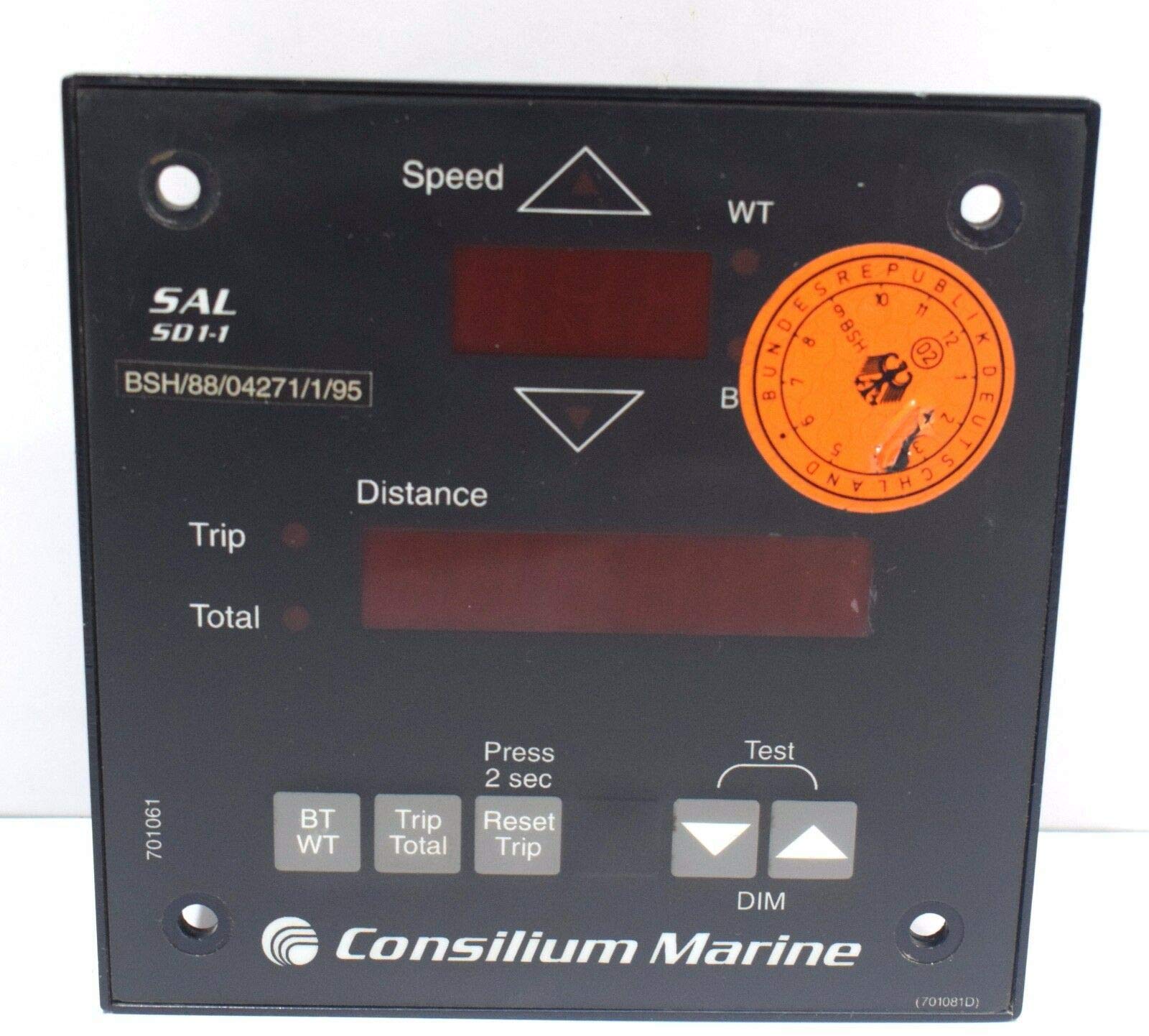
Consilium SAL R30
SAL R30
Doppler · Navigation Data / Sensor · Doppler speed log
Technology
Doppler
IMO Approved
ja
Common Failures & Inspection Points
  • Sensor, antenna or transducer fouling, damage or misalignment causes unstable, missing or inaccurate data
  • Power-supply or processor faults cause resets, blank displays or complete loss of indication
  • Cable, connector or network faults cause intermittent data or loss of outputs to dependent bridge systems
  • Incorrect configuration or calibration causes persistent disagreement with independent references
  • Display, storage or software faults cause frozen values, alarms or unavailable navigation functions
Service: Inspect sensors, antennas, transducers, cabling, power supplies, displays and data interfaces. Compare information with independent references and review alarm history. Verify distribution to dependent bridge systems and confirm approved backup arrangements. Refer to the manufacturer documentation for the exact figure for calibration, alignment and performance criteria.
Spare Parts: Carry fuses, interface cables, approved power supplies, sensor or antenna parts and supported display or processor modules, together with backed-up configuration data where applicable.
Strengths
  • Very high accuracy and low drift compared with electromagnetic logs
  • Real‑time integration with bridge navigation systems (ECDIS, AIS)
  • Robust performance in cold North Sea and Baltic conditions
  • IMO type approval ensures compliance for international voyages
Weaknesses
  • Transducer window often requires replacement during dry‑dock periods
  • Calibration procedure is complex and demands trained personnel
  • Sensitive to power‑supply fluctuations; may need dedicated stabiliser
  • Higher initial cost than basic electromagnetic logs
Typical Vessels: Bulk CarrierContainer ShipTankerPassenger FerryOffshore Supply Vessel
Certifications: IMO Approved
Decision Guide: Choose if you need the highest speed‑through‑water accuracy for fuel‑efficiency monitoring, operate in cold or high‑sea‑state regions, and have access to skilled technicians for calibration. Avoid if budget constraints dominate, power quality is poor on board, or maintenance resources are limited.
Use Cases: Navigation, pilotage, collision avoidance and bridge-system integration.
SAL T30
EM Log · Navigation Data / Sensor · electromagnetic speed log
Technology
Electromagnetic
IMO Approved
ja
Common Failures & Inspection Points
  • Sensor, antenna or transducer fouling, damage or misalignment causes unstable, missing or inaccurate data
  • Power-supply or processor faults cause resets, blank displays or complete loss of indication
  • Cable, connector or network faults cause intermittent data or loss of outputs to dependent bridge systems
  • Incorrect configuration or calibration causes persistent disagreement with independent references
  • Display, storage or software faults cause frozen values, alarms or unavailable navigation functions
Service: Inspect sensors, antennas, transducers, cabling, power supplies, displays and data interfaces. Compare information with independent references and review alarm history. Verify distribution to dependent bridge systems and confirm approved backup arrangements. Refer to the manufacturer documentation for the exact figure for calibration, alignment and performance criteria.
Spare Parts: Carry fuses, interface cables, approved power supplies, sensor or antenna parts and supported display or processor modules, together with backed-up configuration data where applicable.
Strengths
  • Simple EM principle – no rotating parts, reducing mechanical wear
  • IMO approved for SOLAS compliance, meeting mandatory reporting requirements
  • Relatively inexpensive compared with Doppler or acoustic logs
  • Compact installation; fits easily on most bridge consoles
  • Quick deployment and retraction via a single rod
Weaknesses
  • Sensor rod prone to biofouling, especially in warm, nutrient‑rich waters
  • Calibration can drift over time, requiring periodic verification
  • Retractable mechanism seal may leak or seize if not maintained
  • Accuracy degrades at very high speeds (>30 kn) and in turbulent sea states
  • Limited redundancy – only one measurement channel
Typical Vessels: Bulk CarrierGeneral CargoTankerContainer ShipFerryOffshore Supply Vessel
Certifications: IMO Approved
Decision Guide: Choose if: you need a cost‑effective, SOLAS‑compliant speed measurement for vessels operating at moderate speeds and can perform regular cleaning/calibration. Avoid if: high‑precision speed data are critical (e.g., dynamic positioning), the vessel operates in heavy fouling environments, or redundancy is required.
Use Cases: Navigation, pilotage, collision avoidance and bridge-system integration.
FMCW-200 unverified
Type
Doppler
IMO Compliant
ja
Common Failures & Inspection Points
  • Loss of electrical, hydraulic, pneumatic, or other service supply caused by a tripped protection device, leakage, blockage, or upstream fault results in failed starting or loss of function
  • Mechanical wear, corrosion, fouling, or contamination of moving and wetted parts causes increased noise, leakage, sticking, vibration, or reduced performance
  • Seal, gasket, hose, cable, or connection deterioration from age, heat, vibration, or environmental exposure produces visible leakage, intermittent signals, or loss of pressure
  • Sensor, switch, actuator, relay, or control-system faults can cause incorrect indication, nuisance alarms, failed automatic sequences, or loss of remote control
  • Incorrect adjustment, assembly, or maintenance can lead to unstable operation, recurrent alarms, or performance that differs from the vessel's normal baseline
Service: Inspect the unit for leakage, corrosion, contamination, loose connections, abnormal noise or vibration, condition of guards and mountings, service supplies, controls, alarms, and functional performance. Use the vessel maintenance history to identify deterioration trends and refer to the manufacturer documentation for exact settings, tolerances, test values, and overhaul criteria.
Spare Parts: Keep the manufacturer-recommended seals and gaskets, filters where fitted, fuses or protection items, common sensors and switches, and critical actuator, control, or wear components appropriate to the installed configuration. Exact part numbers and quantities must come from the manufacturer spare-parts documentation.
Use Cases: Used on vessel types fitted with position & heading equipment, including merchant, offshore, passenger, fishing, or workboat installations where this specific speed log duty is required.
FMCW-300 unverified
Type
Doppler
IMO Compliant
ja
Common Failures & Inspection Points
  • Loss of electrical, hydraulic, pneumatic, or other service supply caused by a tripped protection device, leakage, blockage, or upstream fault results in failed starting or loss of function
  • Mechanical wear, corrosion, fouling, or contamination of moving and wetted parts causes increased noise, leakage, sticking, vibration, or reduced performance
  • Seal, gasket, hose, cable, or connection deterioration from age, heat, vibration, or environmental exposure produces visible leakage, intermittent signals, or loss of pressure
  • Sensor, switch, actuator, relay, or control-system faults can cause incorrect indication, nuisance alarms, failed automatic sequences, or loss of remote control
  • Incorrect adjustment, assembly, or maintenance can lead to unstable operation, recurrent alarms, or performance that differs from the vessel's normal baseline
Service: Inspect the unit for leakage, corrosion, contamination, loose connections, abnormal noise or vibration, condition of guards and mountings, service supplies, controls, alarms, and functional performance. Use the vessel maintenance history to identify deterioration trends and refer to the manufacturer documentation for exact settings, tolerances, test values, and overhaul criteria.
Spare Parts: Keep the manufacturer-recommended seals and gaskets, filters where fitted, fuses or protection items, common sensors and switches, and critical actuator, control, or wear components appropriate to the installed configuration. Exact part numbers and quantities must come from the manufacturer spare-parts documentation.
Use Cases: Used on vessel types fitted with position & heading equipment, including merchant, offshore, passenger, fishing, or workboat installations where this specific speed log duty is required.
FMCW DS-10 unverified
IMO Compliant
ja
Common Failures & Inspection Points
  • Loss of electrical, hydraulic, pneumatic, or other service supply caused by a tripped protection device, leakage, blockage, or upstream fault results in failed starting or loss of function
  • Mechanical wear, corrosion, fouling, or contamination of moving and wetted parts causes increased noise, leakage, sticking, vibration, or reduced performance
  • Seal, gasket, hose, cable, or connection deterioration from age, heat, vibration, or environmental exposure produces visible leakage, intermittent signals, or loss of pressure
  • Sensor, switch, actuator, relay, or control-system faults can cause incorrect indication, nuisance alarms, failed automatic sequences, or loss of remote control
  • Incorrect adjustment, assembly, or maintenance can lead to unstable operation, recurrent alarms, or performance that differs from the vessel's normal baseline
Service: Inspect the unit for leakage, corrosion, contamination, loose connections, abnormal noise or vibration, condition of guards and mountings, service supplies, controls, alarms, and functional performance. Use the vessel maintenance history to identify deterioration trends and refer to the manufacturer documentation for exact settings, tolerances, test values, and overhaul criteria.
Spare Parts: Keep the manufacturer-recommended seals and gaskets, filters where fitted, fuses or protection items, common sensors and switches, and critical actuator, control, or wear components appropriate to the installed configuration. Exact part numbers and quantities must come from the manufacturer spare-parts documentation.
Use Cases: Used on vessel types fitted with position & heading equipment, including merchant, offshore, passenger, fishing, or workboat installations where this specific speed log duty is required.
FMCW DS-20 unverified
IMO Compliant
ja
Common Failures & Inspection Points
  • Loss of electrical, hydraulic, pneumatic, or other service supply caused by a tripped protection device, leakage, blockage, or upstream fault results in failed starting or loss of function
  • Mechanical wear, corrosion, fouling, or contamination of moving and wetted parts causes increased noise, leakage, sticking, vibration, or reduced performance
  • Seal, gasket, hose, cable, or connection deterioration from age, heat, vibration, or environmental exposure produces visible leakage, intermittent signals, or loss of pressure
  • Sensor, switch, actuator, relay, or control-system faults can cause incorrect indication, nuisance alarms, failed automatic sequences, or loss of remote control
  • Incorrect adjustment, assembly, or maintenance can lead to unstable operation, recurrent alarms, or performance that differs from the vessel's normal baseline
Service: Inspect the unit for leakage, corrosion, contamination, loose connections, abnormal noise or vibration, condition of guards and mountings, service supplies, controls, alarms, and functional performance. Use the vessel maintenance history to identify deterioration trends and refer to the manufacturer documentation for exact settings, tolerances, test values, and overhaul criteria.
Spare Parts: Keep the manufacturer-recommended seals and gaskets, filters where fitted, fuses or protection items, common sensors and switches, and critical actuator, control, or wear components appropriate to the installed configuration. Exact part numbers and quantities must come from the manufacturer spare-parts documentation.
Use Cases: Used on vessel types fitted with position & heading equipment, including merchant, offshore, passenger, fishing, or workboat installations where this specific speed log duty is required.
FMCW DS-30 unverified
IMO Compliant
ja
Common Failures & Inspection Points
  • Loss of electrical, hydraulic, pneumatic, or other service supply caused by a tripped protection device, leakage, blockage, or upstream fault results in failed starting or loss of function
  • Mechanical wear, corrosion, fouling, or contamination of moving and wetted parts causes increased noise, leakage, sticking, vibration, or reduced performance
  • Seal, gasket, hose, cable, or connection deterioration from age, heat, vibration, or environmental exposure produces visible leakage, intermittent signals, or loss of pressure
  • Sensor, switch, actuator, relay, or control-system faults can cause incorrect indication, nuisance alarms, failed automatic sequences, or loss of remote control
  • Incorrect adjustment, assembly, or maintenance can lead to unstable operation, recurrent alarms, or performance that differs from the vessel's normal baseline
Service: Inspect the unit for leakage, corrosion, contamination, loose connections, abnormal noise or vibration, condition of guards and mountings, service supplies, controls, alarms, and functional performance. Use the vessel maintenance history to identify deterioration trends and refer to the manufacturer documentation for exact settings, tolerances, test values, and overhaul criteria.
Spare Parts: Keep the manufacturer-recommended seals and gaskets, filters where fitted, fuses or protection items, common sensors and switches, and critical actuator, control, or wear components appropriate to the installed configuration. Exact part numbers and quantities must come from the manufacturer spare-parts documentation.
Use Cases: Used on vessel types fitted with position & heading equipment, including merchant, offshore, passenger, fishing, or workboat installations where this specific speed log duty is required.

Skipper Electronics

7
Skipper GDS 101 unverified
Type
Doppler
IMO Compliant
ja
Common Failures & Inspection Points
  • Sensor contamination, mechanical damage, ageing, or environmental exposure causes drifting, unstable, or missing measurements
  • Power-supply, fuse, or internal electronic faults cause loss of indication, rebooting, or sensor-offline alarms
  • Cable, connector, network, or interface faults produce intermittent data or loss of information at repeaters and connected systems
  • Incorrect alignment, calibration, configuration, or reference input causes a consistent offset or implausible readings
  • Display, repeater, processor, or software faults can cause frozen values, failed alarms, or disagreement between indications
Service: Check sensor condition and mounting, power supply, cabling, connectors, reference inputs, repeaters, interfaces, alarm history, and comparison with independent indications where practical. Calibration, alignment, and exact accuracy limits must follow manufacturer and statutory documentation.
Spare Parts: Carry approved fuses, connectors, interface modules, display or control items, sensor service parts, and model-specific power-supply components recommended by the manufacturer.
Use Cases: Used on merchant, passenger, offshore, fishing, research, and workboat vessels to support navigation, heading, speed, depth, position, or weather awareness.
Skipper GDS 102 unverified
Type
Doppler
IMO Compliant
ja
Common Failures & Inspection Points
  • Sensor contamination, mechanical damage, ageing, or environmental exposure causes drifting, unstable, or missing measurements
  • Power-supply, fuse, or internal electronic faults cause loss of indication, rebooting, or sensor-offline alarms
  • Cable, connector, network, or interface faults produce intermittent data or loss of information at repeaters and connected systems
  • Incorrect alignment, calibration, configuration, or reference input causes a consistent offset or implausible readings
  • Display, repeater, processor, or software faults can cause frozen values, failed alarms, or disagreement between indications
Service: Check sensor condition and mounting, power supply, cabling, connectors, reference inputs, repeaters, interfaces, alarm history, and comparison with independent indications where practical. Calibration, alignment, and exact accuracy limits must follow manufacturer and statutory documentation.
Spare Parts: Carry approved fuses, connectors, interface modules, display or control items, sensor service parts, and model-specific power-supply components recommended by the manufacturer.
Use Cases: Used on merchant, passenger, offshore, fishing, research, and workboat vessels to support navigation, heading, speed, depth, position, or weather awareness.
Skipper DL850 unverified
Type
Doppler
IMO Compliant
ja
Common Failures & Inspection Points
  • Sensor contamination, mechanical damage, ageing, or environmental exposure causes drifting, unstable, or missing measurements
  • Power-supply, fuse, or internal electronic faults cause loss of indication, rebooting, or sensor-offline alarms
  • Cable, connector, network, or interface faults produce intermittent data or loss of information at repeaters and connected systems
  • Incorrect alignment, calibration, configuration, or reference input causes a consistent offset or implausible readings
  • Display, repeater, processor, or software faults can cause frozen values, failed alarms, or disagreement between indications
Service: Check sensor condition and mounting, power supply, cabling, connectors, reference inputs, repeaters, interfaces, alarm history, and comparison with independent indications where practical. Calibration, alignment, and exact accuracy limits must follow manufacturer and statutory documentation.
Spare Parts: Carry approved fuses, connectors, interface modules, display or control items, sensor service parts, and model-specific power-supply components recommended by the manufacturer.
Use Cases: Used on merchant, passenger, offshore, fishing, research, and workboat vessels to support navigation, heading, speed, depth, position, or weather awareness.
GDS 101 Mk2 unverified
IMO Compliant
ja
Common Failures & Inspection Points
  • Sensor or antenna degradation caused by contamination, damage, ageing or poor exposure can produce missing, unstable or implausible data
  • Connector, cable or network faults caused by vibration, corrosion or disturbed terminations can cause intermittent data loss or interface alarms
  • Power-supply or internal electronics failure caused by ageing, heat or poor ventilation can result in resets, blank indications or complete loss of function
  • Configuration or software errors after service or replacement can cause incorrect data, rejected inputs or loss of communication with other bridge equipment
  • Mechanical damage or water ingress at exposed components can lead to erratic readings, repeated alarms or loss of the affected channel
Service: Inspect exposed sensors or antennas, cable routes, connectors, power supplies, displays and network interfaces. Confirm that indicated or recorded data is plausible and that built-in tests and alarms operate. Compare configuration and test results with the vessel's approved records and manufacturer documentation.
Spare Parts: Keep maker-recommended fuses, connectors, sensor accessories, fans, interface or power modules and other approved line-replaceable items that match the installed configuration.
Use Cases: Commercial ships, passenger vessels, offshore vessels and workboats requiring bridge navigation, recording, environmental or traffic information.
GDS 102 Mk2 unverified
IMO Compliant
ja
Common Failures & Inspection Points
  • Sensor or antenna degradation caused by contamination, damage, ageing or poor exposure can produce missing, unstable or implausible data
  • Connector, cable or network faults caused by vibration, corrosion or disturbed terminations can cause intermittent data loss or interface alarms
  • Power-supply or internal electronics failure caused by ageing, heat or poor ventilation can result in resets, blank indications or complete loss of function
  • Configuration or software errors after service or replacement can cause incorrect data, rejected inputs or loss of communication with other bridge equipment
  • Mechanical damage or water ingress at exposed components can lead to erratic readings, repeated alarms or loss of the affected channel
Service: Inspect exposed sensors or antennas, cable routes, connectors, power supplies, displays and network interfaces. Confirm that indicated or recorded data is plausible and that built-in tests and alarms operate. Compare configuration and test results with the vessel's approved records and manufacturer documentation.
Spare Parts: Keep maker-recommended fuses, connectors, sensor accessories, fans, interface or power modules and other approved line-replaceable items that match the installed configuration.
Use Cases: Commercial ships, passenger vessels, offshore vessels and workboats requiring bridge navigation, recording, environmental or traffic information.
DL850 Mk2 unverified
IMO Compliant
ja
Common Failures & Inspection Points
  • Sensor or antenna degradation caused by contamination, damage, ageing or poor exposure can produce missing, unstable or implausible data
  • Connector, cable or network faults caused by vibration, corrosion or disturbed terminations can cause intermittent data loss or interface alarms
  • Power-supply or internal electronics failure caused by ageing, heat or poor ventilation can result in resets, blank indications or complete loss of function
  • Configuration or software errors after service or replacement can cause incorrect data, rejected inputs or loss of communication with other bridge equipment
  • Mechanical damage or water ingress at exposed components can lead to erratic readings, repeated alarms or loss of the affected channel
Service: Inspect exposed sensors or antennas, cable routes, connectors, power supplies, displays and network interfaces. Confirm that indicated or recorded data is plausible and that built-in tests and alarms operate. Compare configuration and test results with the vessel's approved records and manufacturer documentation.
Spare Parts: Keep maker-recommended fuses, connectors, sensor accessories, fans, interface or power modules and other approved line-replaceable items that match the installed configuration.
Use Cases: Commercial ships, passenger vessels, offshore vessels and workboats requiring bridge navigation, recording, environmental or traffic information.
DL860 unverified
IMO Compliant
ja
Common Failures & Inspection Points
  • Loss of electrical, hydraulic, pneumatic, or other service supply caused by a tripped protection device, leakage, blockage, or upstream fault results in failed starting or loss of function
  • Mechanical wear, corrosion, fouling, or contamination of moving and wetted parts causes increased noise, leakage, sticking, vibration, or reduced performance
  • Seal, gasket, hose, cable, or connection deterioration from age, heat, vibration, or environmental exposure produces visible leakage, intermittent signals, or loss of pressure
  • Sensor, switch, actuator, relay, or control-system faults can cause incorrect indication, nuisance alarms, failed automatic sequences, or loss of remote control
  • Incorrect adjustment, assembly, or maintenance can lead to unstable operation, recurrent alarms, or performance that differs from the vessel's normal baseline
Service: Inspect the unit for leakage, corrosion, contamination, loose connections, abnormal noise or vibration, condition of guards and mountings, service supplies, controls, alarms, and functional performance. Use the vessel maintenance history to identify deterioration trends and refer to the manufacturer documentation for exact settings, tolerances, test values, and overhaul criteria.
Spare Parts: Keep the manufacturer-recommended seals and gaskets, filters where fitted, fuses or protection items, common sensors and switches, and critical actuator, control, or wear components appropriate to the installed configuration. Exact part numbers and quantities must come from the manufacturer spare-parts documentation.
Use Cases: Used on vessel types fitted with position & heading equipment, including merchant, offshore, passenger, fishing, or workboat installations where this specific speed log duty is required.

Tokyo Keiki

7
ES-4200 unverified
Type
Electromagnetic
IMO Compliant
ja
Common Failures & Inspection Points
  • Sensor fouling, marine growth or damage causes low, erratic or missing speed readings
  • Cabling or transducer faults cause intermittent data or complete loss of speed indication
  • Incorrect calibration or setup causes a persistent difference from expected vessel speed
  • Processor or display faults cause frozen values, alarms or loss of output to other bridge systems
  • Air bubbles, aeration or disturbed water flow around the sensor cause unstable readings under certain operating conditions
Service: Inspect accessible transducer connections, cabling, processor and display. Compare indicated speed with independent references while considering current and sensor type. Check data output to radar, ECDIS and other consumers. Exact calibration values and docking inspection criteria require manufacturer documentation.
Spare Parts: Carry fuses, interface cables, approved processor or display modules and transducer service components where supported.
Use Cases: Navigation and bridge sensor integration on commercial, offshore and passenger vessels.
ES-5100 unverified
Type
Doppler
IMO Compliant
ja
Common Failures & Inspection Points
  • Sensor fouling, marine growth or damage causes low, erratic or missing speed readings
  • Cabling or transducer faults cause intermittent data or complete loss of speed indication
  • Incorrect calibration or setup causes a persistent difference from expected vessel speed
  • Processor or display faults cause frozen values, alarms or loss of output to other bridge systems
  • Air bubbles, aeration or disturbed water flow around the sensor cause unstable readings under certain operating conditions
Service: Inspect accessible transducer connections, cabling, processor and display. Compare indicated speed with independent references while considering current and sensor type. Check data output to radar, ECDIS and other consumers. Exact calibration values and docking inspection criteria require manufacturer documentation.
Spare Parts: Carry fuses, interface cables, approved processor or display modules and transducer service components where supported.
Use Cases: Navigation and bridge sensor integration on commercial, offshore and passenger vessels.
ES-5200 unverified
Type
Doppler
IMO Compliant
ja
Common Failures & Inspection Points
  • Sensor fouling, marine growth or damage causes low, erratic or missing speed readings
  • Cabling or transducer faults cause intermittent data or complete loss of speed indication
  • Incorrect calibration or setup causes a persistent difference from expected vessel speed
  • Processor or display faults cause frozen values, alarms or loss of output to other bridge systems
  • Air bubbles, aeration or disturbed water flow around the sensor cause unstable readings under certain operating conditions
Service: Inspect accessible transducer connections, cabling, processor and display. Compare indicated speed with independent references while considering current and sensor type. Check data output to radar, ECDIS and other consumers. Exact calibration values and docking inspection criteria require manufacturer documentation.
Spare Parts: Carry fuses, interface cables, approved processor or display modules and transducer service components where supported.
Use Cases: Navigation and bridge sensor integration on commercial, offshore and passenger vessels.
ES-5200 SDME unverified
IMO Compliant
ja
Common Failures & Inspection Points
  • Sensor, antenna or transducer fouling, damage or misalignment causes unstable, missing or inaccurate data
  • Power-supply or processor faults cause resets, blank displays or complete loss of indication
  • Cable, connector or network faults cause intermittent data or loss of outputs to other bridge systems
  • Incorrect configuration or calibration causes persistent disagreement with independent references
  • Display or software faults cause frozen values, alarms or unavailable functions
Service: Inspect sensors, antennas, transducers, cabling, power supplies, displays and data interfaces. Compare information with independent references and review alarm history. Verify distribution to dependent bridge systems. Refer to the manufacturer documentation for the exact figure for calibration, alignment and performance criteria.
Spare Parts: Carry fuses, interface cables, approved power supplies, sensor or antenna parts and supported display or processor modules.
Use Cases: Navigation, pilotage, collision avoidance and bridge-system integration.
ES-5300 Mk2 unverified
IMO Compliant
ja
Common Failures & Inspection Points
  • Sensor or antenna fault caused by fouling, damage, wear or water ingress, resulting in loss, weak response or degraded navigation data
  • Power-supply failure caused by breaker, converter or wiring problems, resulting in loss of indication
  • Processor or display fault caused by electronics or software problems, resulting in frozen, blank or erroneous output
  • Interface or network failure caused by cabling or configuration faults, resulting in missing data at connected bridge equipment
  • Calibration, alignment or configuration error caused by incorrect setup or maintenance, resulting in persistent disagreement with independent navigation references
Service: Compare the indicated value with independent references and investigate persistent disagreement rather than applying unrecorded corrections. Inspect sensors, antennas, transducers, cabling, power supplies, repeaters and network interfaces applicable to the installed equipment. Verify alarms and data outputs to radar, ECDIS, autopilot and voyage-data systems where connected. Keep calibration, deviation or configuration records current as appropriate to the sensor type. Protect exposed sensors and transducers from paint, deposits and water ingress. Refer to manufacturer and bridge-equipment documentation for exact test, calibration and alignment procedures.
Spare Parts: Keep fuses, lamps or display consumables, selected power-supply and interface modules, cables or connectors and manufacturer-recommended sensor service parts. Replacement core sensors, antennas or processors must remain compatible with the approved bridge installation. Preserve calibration and configuration data when changing equipment.
Use Cases: Bridge navigation and sensor input for collision avoidance, route monitoring, steering, depth awareness and other shipboard navigation functions according to the equipment category.
ES-4200 EM Mk2 unverified
IMO Compliant
ja
Common Failures & Inspection Points
  • Loss of electrical, hydraulic, pneumatic, or other service supply caused by a tripped protection device, leakage, blockage, or upstream fault results in failed starting or loss of function
  • Mechanical wear, corrosion, fouling, or contamination of moving and wetted parts causes increased noise, leakage, sticking, vibration, or reduced performance
  • Seal, gasket, hose, cable, or connection deterioration from age, heat, vibration, or environmental exposure produces visible leakage, intermittent signals, or loss of pressure
  • Sensor, switch, actuator, relay, or control-system faults can cause incorrect indication, nuisance alarms, failed automatic sequences, or loss of remote control
  • Incorrect adjustment, assembly, or maintenance can lead to unstable operation, recurrent alarms, or performance that differs from the vessel's normal baseline
Service: Inspect the unit for leakage, corrosion, contamination, loose connections, abnormal noise or vibration, condition of guards and mountings, service supplies, controls, alarms, and functional performance. Use the vessel maintenance history to identify deterioration trends and refer to the manufacturer documentation for exact settings, tolerances, test values, and overhaul criteria.
Spare Parts: Keep the manufacturer-recommended seals and gaskets, filters where fitted, fuses or protection items, common sensors and switches, and critical actuator, control, or wear components appropriate to the installed configuration. Exact part numbers and quantities must come from the manufacturer spare-parts documentation.
Use Cases: Used on vessel types fitted with position & heading equipment, including merchant, offshore, passenger, fishing, or workboat installations where this specific speed log duty is required.
ES-6000 unverified
IMO Compliant
ja
Common Failures & Inspection Points
  • Sensor fouling, marine growth or damage causes low, erratic or missing speed readings
  • Cabling or transducer faults cause intermittent data or complete loss of speed indication
  • Incorrect calibration or setup causes a persistent difference from expected vessel speed
  • Processor or display faults cause frozen values, alarms or loss of output to other bridge systems
  • Air bubbles, aeration or disturbed water flow around the sensor cause unstable readings under certain operating conditions
Service: Inspect accessible transducer connections, cabling, processor and display. Compare indicated speed with independent references while considering current and sensor type. Check data output to radar, ECDIS and other consumers. Exact calibration values and docking inspection criteria require manufacturer documentation.
Spare Parts: Carry fuses, interface cables, approved processor or display modules and transducer service components where supported.
Use Cases: Navigation and bridge sensor integration on commercial, offshore and passenger vessels.

JRC (Japan Radio Co)

6
JLN-205 unverified
Type
Electromagnetic
IMO Compliant
ja
Common Failures & Inspection Points
  • Loss of electrical, hydraulic, pneumatic, or other service supply caused by a tripped protection device, leakage, blockage, or upstream fault results in failed starting or loss of function
  • Mechanical wear, corrosion, fouling, or contamination of moving and wetted parts causes increased noise, leakage, sticking, vibration, or reduced performance
  • Seal, gasket, hose, cable, or connection deterioration from age, heat, vibration, or environmental exposure produces visible leakage, intermittent signals, or loss of pressure
  • Sensor, switch, actuator, relay, or control-system faults can cause incorrect indication, nuisance alarms, failed automatic sequences, or loss of remote control
  • Incorrect adjustment, assembly, or maintenance can lead to unstable operation, recurrent alarms, or performance that differs from the vessel's normal baseline
Service: Inspect the unit for leakage, corrosion, contamination, loose connections, abnormal noise or vibration, condition of guards and mountings, service supplies, controls, alarms, and functional performance. Use the vessel maintenance history to identify deterioration trends and refer to the manufacturer documentation for exact settings, tolerances, test values, and overhaul criteria.
Spare Parts: Keep the manufacturer-recommended seals and gaskets, filters where fitted, fuses or protection items, common sensors and switches, and critical actuator, control, or wear components appropriate to the installed configuration. Exact part numbers and quantities must come from the manufacturer spare-parts documentation.
Use Cases: Used on vessel types fitted with position & heading equipment, including merchant, offshore, passenger, fishing, or workboat installations where this specific speed log duty is required.
JLN-740A unverified
Type
Doppler
IMO Compliant
ja
Common Failures & Inspection Points
  • Loss of electrical, hydraulic, pneumatic, or other service supply caused by a tripped protection device, leakage, blockage, or upstream fault results in failed starting or loss of function
  • Mechanical wear, corrosion, fouling, or contamination of moving and wetted parts causes increased noise, leakage, sticking, vibration, or reduced performance
  • Seal, gasket, hose, cable, or connection deterioration from age, heat, vibration, or environmental exposure produces visible leakage, intermittent signals, or loss of pressure
  • Sensor, switch, actuator, relay, or control-system faults can cause incorrect indication, nuisance alarms, failed automatic sequences, or loss of remote control
  • Incorrect adjustment, assembly, or maintenance can lead to unstable operation, recurrent alarms, or performance that differs from the vessel's normal baseline
Service: Inspect the unit for leakage, corrosion, contamination, loose connections, abnormal noise or vibration, condition of guards and mountings, service supplies, controls, alarms, and functional performance. Use the vessel maintenance history to identify deterioration trends and refer to the manufacturer documentation for exact settings, tolerances, test values, and overhaul criteria.
Spare Parts: Keep the manufacturer-recommended seals and gaskets, filters where fitted, fuses or protection items, common sensors and switches, and critical actuator, control, or wear components appropriate to the installed configuration. Exact part numbers and quantities must come from the manufacturer spare-parts documentation.
Use Cases: Used on vessel types fitted with position & heading equipment, including merchant, offshore, passenger, fishing, or workboat installations where this specific speed log duty is required.
JLN-741 unverified
Type
Doppler
IMO Compliant
ja
Common Failures & Inspection Points
  • Loss of electrical, hydraulic, pneumatic, or other service supply caused by a tripped protection device, leakage, blockage, or upstream fault results in failed starting or loss of function
  • Mechanical wear, corrosion, fouling, or contamination of moving and wetted parts causes increased noise, leakage, sticking, vibration, or reduced performance
  • Seal, gasket, hose, cable, or connection deterioration from age, heat, vibration, or environmental exposure produces visible leakage, intermittent signals, or loss of pressure
  • Sensor, switch, actuator, relay, or control-system faults can cause incorrect indication, nuisance alarms, failed automatic sequences, or loss of remote control
  • Incorrect adjustment, assembly, or maintenance can lead to unstable operation, recurrent alarms, or performance that differs from the vessel's normal baseline
Service: Inspect the unit for leakage, corrosion, contamination, loose connections, abnormal noise or vibration, condition of guards and mountings, service supplies, controls, alarms, and functional performance. Use the vessel maintenance history to identify deterioration trends and refer to the manufacturer documentation for exact settings, tolerances, test values, and overhaul criteria.
Spare Parts: Keep the manufacturer-recommended seals and gaskets, filters where fitted, fuses or protection items, common sensors and switches, and critical actuator, control, or wear components appropriate to the installed configuration. Exact part numbers and quantities must come from the manufacturer spare-parts documentation.
Use Cases: Used on vessel types fitted with position & heading equipment, including merchant, offshore, passenger, fishing, or workboat installations where this specific speed log duty is required.
JLN-740A Mk2 unverified
IMO Compliant
ja
Common Failures & Inspection Points
  • Sensor contamination, mechanical damage, ageing, or environmental exposure causes drifting, unstable, or missing measurements
  • Power-supply, fuse, or internal electronic faults cause loss of indication, rebooting, or sensor-offline alarms
  • Cable, connector, network, or interface faults produce intermittent data or loss of information at repeaters and connected systems
  • Incorrect alignment, calibration, configuration, or reference input causes a consistent offset or implausible readings
  • Display, repeater, processor, or software faults can cause frozen values, failed alarms, or disagreement between indications
Service: Check sensor condition and mounting, power supply, cabling, connectors, reference inputs, repeaters, interfaces, alarm history, and comparison with independent indications where practical. Calibration, alignment, and exact accuracy limits must follow manufacturer and statutory documentation.
Spare Parts: Carry approved fuses, connectors, interface modules, display or control items, sensor service parts, and model-specific power-supply components recommended by the manufacturer.
Use Cases: Used on merchant, passenger, offshore, fishing, research, and workboat vessels to support navigation, heading, speed, depth, position, or weather awareness.
JLN-741 Mk2 unverified
IMO Compliant
ja
Common Failures & Inspection Points
  • Sensor or antenna degradation caused by contamination, damage, ageing or poor exposure can produce missing, unstable or implausible data
  • Connector, cable or network faults caused by vibration, corrosion or disturbed terminations can cause intermittent data loss or interface alarms
  • Power-supply or internal electronics failure caused by ageing, heat or poor ventilation can result in resets, blank indications or complete loss of function
  • Configuration or software errors after service or replacement can cause incorrect data, rejected inputs or loss of communication with other bridge equipment
  • Mechanical damage or water ingress at exposed components can lead to erratic readings, repeated alarms or loss of the affected channel
Service: Inspect exposed sensors or antennas, cable routes, connectors, power supplies, displays and network interfaces. Confirm that indicated or recorded data is plausible and that built-in tests and alarms operate. Compare configuration and test results with the vessel's approved records and manufacturer documentation.
Spare Parts: Keep maker-recommended fuses, connectors, sensor accessories, fans, interface or power modules and other approved line-replaceable items that match the installed configuration.
Use Cases: Commercial ships, passenger vessels, offshore vessels and workboats requiring bridge navigation, recording, environmental or traffic information.
JLN-205 Mk2 unverified
IMO Compliant
ja
Common Failures & Inspection Points
  • Sensor or antenna degradation caused by contamination, damage, ageing or poor exposure can produce missing, unstable or implausible data
  • Connector, cable or network faults caused by vibration, corrosion or disturbed terminations can cause intermittent data loss or interface alarms
  • Power-supply or internal electronics failure caused by ageing, heat or poor ventilation can result in resets, blank indications or complete loss of function
  • Configuration or software errors after service or replacement can cause incorrect data, rejected inputs or loss of communication with other bridge equipment
  • Mechanical damage or water ingress at exposed components can lead to erratic readings, repeated alarms or loss of the affected channel
Service: Inspect exposed sensors or antennas, cable routes, connectors, power supplies, displays and network interfaces. Confirm that indicated or recorded data is plausible and that built-in tests and alarms operate. Compare configuration and test results with the vessel's approved records and manufacturer documentation.
Spare Parts: Keep maker-recommended fuses, connectors, sensor accessories, fans, interface or power modules and other approved line-replaceable items that match the installed configuration.
Use Cases: Commercial ships, passenger vessels, offshore vessels and workboats requiring bridge navigation, recording, environmental or traffic information.

SAL Navigation

3
SAL Navigation JLN900 Speed log system
Model Number
TAA00003MF
SAL Navigation AB SAL Navigation T200, T2+ Speed log system
SAL Navigation T200, T2+ Speed log system
Model Number
TAA00003MG
SAL R100 Speed Log System
Model Number
TAA00003KE

JRC

2
JRC JLN-740A
JLN-740A
Doppler / dual-axis · Navigation Data / Sensor · Doppler bottom-track speed log
Technology
Doppler
Bottom track depth
400 m
IMO Approved
ja
Common Failures & Inspection Points
  • Sensor, antenna or transducer fouling, damage or misalignment causes unstable, missing or inaccurate data
  • Power-supply or processor faults cause resets, blank displays or complete loss of indication
  • Cable, connector or network faults cause intermittent data or loss of outputs to dependent bridge systems
  • Incorrect configuration or calibration causes persistent disagreement with independent references
  • Display, storage or software faults cause frozen values, alarms or unavailable navigation functions
Service: Inspect sensors, antennas, transducers, cabling, power supplies, displays and data interfaces. Compare information with independent references and review alarm history. Verify distribution to dependent bridge systems and confirm approved backup arrangements. Refer to the manufacturer documentation for the exact figure for calibration, alignment and performance criteria.
Spare Parts: Carry fuses, interface cables, approved power supplies, sensor or antenna parts and supported display or processor modules, together with backed-up configuration data where applicable.
Strengths
  • Accurate speed measurement in deep water (up to 400 m)
  • IMO type approval for compliance with international regulations
  • Robust performance on long ocean voyages and offshore operations
  • Integrated display processor simplifies bridge integration
  • Annual transducer inspection schedule supports preventive maintenance
Weaknesses
  • Transducer susceptible to cavitation damage at high vessel speeds
  • Bottom‑track lock can be lost in very deep or turbulent water conditions
  • Reported occasional failures of the display/processor unit
  • Requires regular inspection and possible replacement of transducer elements
  • Higher initial cost compared with basic paddlewheel logs
Typical Vessels: Crude oil tankersLNG carriersOffshore supply vesselsResearch / survey shipsLarge container or cruise ships operating on deep‑sea routes
Certifications: IMO Type Approval
Decision Guide: Choose if the vessel needs reliable speed data in deep water, must meet IMO equipment standards, and operates primarily at moderate speeds where cavitation risk is low. Avoid if the ship routinely runs at very high speeds, operates in extremely shallow or highly turbulent waters, or if budget constraints limit acceptance of higher‑maintenance Doppler systems.
Use Cases: Navigation, pilotage, collision avoidance and bridge-system integration.
JRC JLN-205
JLN-205
EM Log · Navigation Data / Sensor · electromagnetic speed log
Technology
Electromagnetic
IMO Approved
ja
Common Failures & Inspection Points
  • Sensor, antenna or transducer fouling, damage or misalignment causes unstable, missing or inaccurate data
  • Power-supply or processor faults cause resets, blank displays or complete loss of indication
  • Cable, connector or network faults cause intermittent data or loss of outputs to dependent bridge systems
  • Incorrect configuration or calibration causes persistent disagreement with independent references
  • Display, storage or software faults cause frozen values, alarms or unavailable navigation functions
Service: Inspect sensors, antennas, transducers, cabling, power supplies, displays and data interfaces. Compare information with independent references and review alarm history. Verify distribution to dependent bridge systems and confirm approved backup arrangements. Refer to the manufacturer documentation for the exact figure for calibration, alignment and performance criteria.
Spare Parts: Carry fuses, interface cables, approved power supplies, sensor or antenna parts and supported display or processor modules, together with backed-up configuration data where applicable.
Strengths
  • No moving parts in the water, reducing mechanical wear and maintenance
  • IMO Type Approval ensures compliance with SOLAS navigation requirements
  • Retractable sensor rod can be safely stowed for dry‑dock or when not in use
  • Annual calibration procedure maintains measurement accuracy
Weaknesses
  • Sensor rod is susceptible to fouling in heavy biofouling environments
  • Seal on the retractable rod may develop leaks, requiring periodic inspection
  • Calibration drift can occur if annual recalibration is missed
  • Requires compatible bridge integration; not a plug‑and‑play solution for all vessels
Typical Vessels: TankerContainer shipBulk carrierGeneral cargo vesselCruise shipOffshore supply vessel
Certifications: IMO Type Approval
Decision Guide: Choose if: you need an IMO‑approved, low‑maintenance speed measurement system with high accuracy and a retractable sensor for easy dry‑dock handling. Avoid if: the vessel operates in extreme fouling conditions where rod cleaning is impractical, or budget constraints preclude annual calibration costs.
Use Cases: Navigation, pilotage, collision avoidance and bridge-system integration.

Kongsberg Maritime

1
Kongsberg EM Speed Log
EM Speed Log
EM Log · Navigation Data / Sensor · electromagnetic speed log
Technology
Electromagnetic
IMO Approved
ja
Common Failures & Inspection Points
  • Sensor, antenna or transducer fouling, damage or misalignment causes unstable, missing or inaccurate data
  • Power-supply or processor faults cause resets, blank displays or complete loss of indication
  • Cable, connector or network faults cause intermittent data or loss of outputs to dependent bridge systems
  • Incorrect configuration or calibration causes persistent disagreement with independent references
  • Display, storage or software faults cause frozen values, alarms or unavailable navigation functions
Service: Inspect sensors, antennas, transducers, cabling, power supplies, displays and data interfaces. Compare information with independent references and review alarm history. Verify distribution to dependent bridge systems and confirm approved backup arrangements. Refer to the manufacturer documentation for the exact figure for calibration, alignment and performance criteria.
Spare Parts: Carry fuses, interface cables, approved power supplies, sensor or antenna parts and supported display or processor modules, together with backed-up configuration data where applicable.
Strengths
  • Non‑contact measurement – no rotating paddles, resulting in very low mechanical wear
  • High accuracy over a wide range of speeds and sea states
  • Integrated directly with K‑Bridge for seamless data display and logging
  • Effective in shallow draft vessels where paddle wheels are impractical
  • Low routine maintenance compared with mechanical logs
Weaknesses
  • Probe surface can suffer biofouling, degrading accuracy if not regularly cleaned
  • Calibration may drift when hull fouling changes the flow profile around the sensor
  • Requires a clean‑hull installation area; retrofits on heavily fouled ships can be difficult
  • Electromagnetic interference from nearby high‑power equipment can affect readings
  • Higher upfront cost than basic paddlewheel speed logs
Typical Vessels: TankerContainer shipBulk carrierCruise linerOffshore support vesselFerry
Certifications: IMO D-2
Decision Guide: Choose if you need precise speed‑through‑water data for navigation, fuel‑efficiency monitoring, DP or emissions reporting and prefer a low‑maintenance, bridge‑integrated solution. Avoid if the vessel operates in environments with extreme biofouling risk, has limited budget for instrumentation, or cannot provide a clean hull area for sensor installation.
Use Cases: Navigation, pilotage, collision avoidance and bridge-system integration.

Skipper

1
DL850 Doppler Log
Doppler · Navigation Data / Sensor · Doppler speed log
Technology
Doppler
IMO Approved
ja
Common Failures & Inspection Points
  • Sensor, antenna or transducer fouling, damage or misalignment causes unstable, missing or inaccurate data
  • Power-supply or processor faults cause resets, blank displays or complete loss of indication
  • Cable, connector or network faults cause intermittent data or loss of outputs to dependent bridge systems
  • Incorrect configuration or calibration causes persistent disagreement with independent references
  • Display, storage or software faults cause frozen values, alarms or unavailable navigation functions
Service: Inspect sensors, antennas, transducers, cabling, power supplies, displays and data interfaces. Compare information with independent references and review alarm history. Verify distribution to dependent bridge systems and confirm approved backup arrangements. Refer to the manufacturer documentation for the exact figure for calibration, alignment and performance criteria.
Spare Parts: Carry fuses, interface cables, approved power supplies, sensor or antenna parts and supported display or processor modules, together with backed-up configuration data where applicable.
Strengths
  • High accuracy in low‑temperature sea water conditions
  • IMO approved, meeting international navigation standards
  • Compact bridge‑mounted unit with built‑in display
  • Robust housing suited to Arctic and sub‑Arctic environments
Weaknesses
  • Limited service and spare‑parts network outside Scandinavia
  • Transducer compatibility restricted to Skipper‑specified models
  • Occasional display firmware glitches reported by users
  • Less flexible integration with non‑Skipper bridge systems
Typical Vessels: Offshore supply vesselIce‑class bulk carrierArctic tankerGeneral cargo ship operating in cold regions
Certifications: IMO Approved
Decision Guide: Choose if the vessel operates primarily in cold or Arctic waters, requires an IMO‑approved Doppler log and can rely on Scandinavian support facilities. Avoid if the ship sails far from Scandinavia, needs a wide range of interchangeable transducers, or must integrate with non‑Skipper bridge consoles.
Use Cases: Navigation, pilotage, collision avoidance and bridge-system integration.

Tokimec

1
TL-250
EM Log · Navigation Data / Sensor · Electromagnetic speed log
Technology
Electromagnetic
IMO Approved
ja
Common Failures & Inspection Points
  • Sensor, antenna or transducer fouling, damage or misalignment causes unstable, missing or inaccurate data
  • Power-supply or processor faults cause resets, blank displays or complete loss of indication
  • Cable, connector or network faults cause intermittent data or loss of outputs to dependent bridge systems
  • Incorrect configuration or calibration causes persistent disagreement with independent references
  • Display, storage or software faults cause frozen values, alarms or unavailable navigation functions
Service: Inspect sensors, antennas, transducers, cabling, power supplies, displays and data interfaces. Compare information with independent references and review alarm history. Verify distribution to dependent bridge systems and confirm approved backup arrangements. Refer to the manufacturer documentation for the exact figure for calibration, alignment and performance criteria.
Spare Parts: Carry fuses, interface cables, approved power supplies, sensor or antenna parts and supported display or processor modules, together with backed-up configuration data where applicable.
Strengths
  • No moving parts – low mechanical wear and maintenance
  • Accurate at low to moderate speeds on steel hulls
  • IMO type approval satisfies SOLAS speed‑log requirements
  • Proven field service record on many commercial vessels
  • Compatible with standard bridge integration packages
Weaknesses
  • Sensor rod can age, leading to drift if not recalibrated
  • Spare‑parts availability reduced after brand transition to Tokyo Keiki
  • Legacy Tokimec branding may cause procurement confusion
  • Performance degrades on non‑magnetic (composite or aluminum) hulls
  • Limited depth range compared with Doppler‑based logs
Typical Vessels: TankerBulk CarrierContainer ShipPassenger / Cruise VesselOffshore Supply Vessel
Certifications: IMO Type Approval
Decision Guide: Choose if: you need a low‑maintenance, IMO‑approved speed measurement on steel hulls and have existing support for Tokimec/Tokyo Keiki equipment. Avoid if: the vessel has a composite or aluminum hull, you require high‑depth Doppler performance, or spare‑part logistics are critical and parts are scarce.
Use Cases: Navigation, pilotage, collision avoidance and bridge-system integration.

YDK Technologies Co., Ltd., Morioka Branch

1
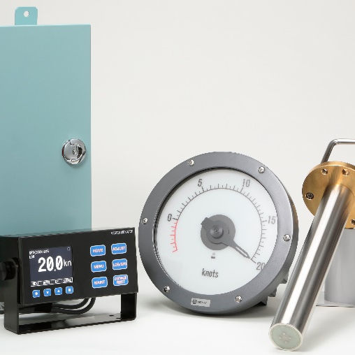
YDK Technologies Co., Ltd., Morioka Branch EML900 Electromagnetic log
EML900 Electromagnetic log
Model Number
TAA00003TA