Portable Tank Cleaning Gun
A portable tank cleaning gun reaches the corners a fixed rotary tank cleaning machine misses, connected by hose to the ship's washing water or chemical supply and worked by hand inside the tank rather than lowered through a deck hatch.
Read more — Portable Tank Cleaning Gun explained ▾
What sets a portable gun apart
A portable tank cleaning gun is a hand-carried, hose-fed nozzle used inside a cargo or ballast tank for spot cleaning, in contrast to a fixed rotary tank cleaning machine that is lowered through a deck hatch and left to run unattended on a programmed cycle. It earns its place where a fixed machine cannot reach — stiffeners, corners, pump wells — or where the ship has no fixed system fitted at all, typically smaller tankers, chemical carriers and tank barges.
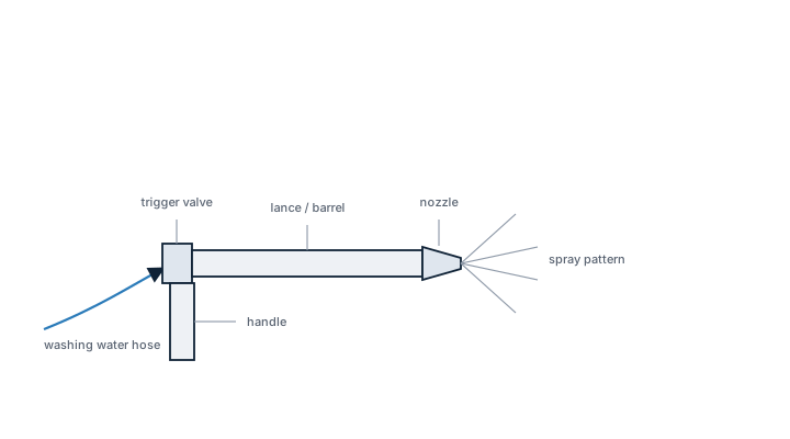
Main components
- Gun body with a hand trigger or lever valve controlling flow to the nozzle.
- Rotating nozzle head, single or multi-jet, driven by the reaction force of the water itself so it needs no separate motor.
- Hose connection, usually a camlock or similar quick-connect fitting to the ship's washing hose.
- Lance or extension pipe to reach into corners and along stiffeners without the operator having to climb into every recess.
- On some models, a small in-line chemical injection point for detergent dosing.
Selection and sizing
Flow rate and working pressure have to match what the ship's tank cleaning pump and heater can actually deliver — a gun rated well above the supply pressure will simply underperform. Material matters more than on most deck equipment: stainless steel construction avoids introducing contamination into a cargo tank, particularly on chemical carriers where cargo compatibility is checked closely. Lance length is chosen against the tank's internal structure, and jet pattern, fan versus concentrated jet, against whether the job is bulk residue removal or spot cleaning of a stubborn deposit.
Typical faults
| Fault | Cause | Consequence |
|---|---|---|
| Nozzle wear | Abrasive residue passing through the jets over repeated use | Reduced jet pressure and uneven wash coverage, longer cleaning times |
| Trigger or valve seal failure | Ageing seals or exposure to aggressive cleaning chemicals | Leakage past the trigger, operator exposure to wash medium |
| Hose connection corrosion | Wrong material for the cargo or cleaning chemical in use | Pressure loss, and in a worst case a blowout under pressure inside the tank |
| Rotating head seizure | Bearing wear or debris ingress | Gun stops rotating, leaving a visible unwashed streak in the pattern |
What to look for in a supplier
- Material and seal compatibility with the range of cargoes the ship actually carries, not a generic freshwater rating.
- A pressure rating that matches, rather than exceeds, the ship's cleaning pump discharge.
- Spare nozzles and seals sized for the specific model, since these are consumable parts.
A gun with a seized head still sprays water, so the fault is easy to miss from outside the tank until the wash pattern shows an unwashed streak — check rotation before sending anyone in to finish the job by hand.
3 manufacturers · 60 models
Alfa Laval
20- Durchsatzbereich
- i40 S: 3-56 m³/h | i40 D: 7-80 m³/h | TZ-82: 15 m³/h (8mm-Düsen @ 7 bar)
- Betriebsdruck
- Typischerweise 4-12 bar; empfohlener Betriebsdruck 5-6,5 bar
- Wurfweite/reichweite
- TZ-82: 26 Meter horizontale Wurfweite (Benetzungsradius)
- Düsendurchmesser-Bereich
- 7-10 mm (verschiedene Konfigurationen für Durchsatz-Optimierung)
- Deck-Öffnung erforderlich
- i40 S/i40 D: nur 145 mm (kompakteste 2. Generation)
- Material-standard
- AISI 316 Edelstahl für Hauptkomponenten; PEEK für Seals/Verschleißteile
- Betriebstemperatur
- 0–95°C (32–203°F)
- Antriebsart
- Turbine-driven by cleaning medium flow (COW: crude oil washthrough possible)
- IMO-Konformität
- Erfüllt IMO-Anforderungen für COW (Crude Oil Washing) Systeme
- i40 S (Single-Nozzle, 2. Generation)
- i40 D (Dual-Nozzle, 2. Generation)
- i65 S (Single-Nozzle, High-Impact)
- T-73 (Automatic, 5.000-30.000 m³)
- TZ-67 (Rotary Jet Head, 50-500 m³)
- TZ-75 (Portable, 1.000-5.000 m³)
- TZ-82 (Portable/Fixed, bis 3.000 m³)
- TZ-89 (Media-Lubricated)
- 270FT Mark I (Single-Nozzle Crude Oil Tanker)
- Area: Nozzle wear and erosionCheck: Inspectors regularly check nozzles for wear marks, scratches, surface erosion and deformed openings. Nozzle blockages from sludge accumulation are the most frequent periodic maintenance task. Damaged nozzles must be replaced as a group.
- Area: Gearbox/turbine wear and vibrationCheck: Inspectors monitor for abnormal vibrations, temperature rise and irregular noise. Detached gear teeth and uneven disk distribution cause vibration problems. Inspection recommended every 200-300 operating hours; bearing replacement after 300-500 hours or at least every 3 years.
- Area: Ball bearings and sleeve bushings wearCheck: Inspectors check ball bearings for free rotation without contamination and damage. Sleeve bushings in gearbox frame must be checked: maximum diameter not exceeding 10.4 mm (bore not ovally deformed). Inspect all bearings and sealing rings every 6 months; replacement after 6,000 operating hours or every 3 years.
- Area: Seals and shaft passages (hysteresis coupling design)Check: Inspectors check for oil leakage and contamination at seal points. The hysteresis coupling eliminates conventional speed-setting shafts and reduces leak points. All rubber seals should be replaced at each service inspection to ensure hygiene and performance. Moisture and contamination ingress leads to seal failure.
- Area: Programming pattern and control sequence functionalityCheck: Inspectors test programming logic and valve control for correct 3D-indexed impact pattern. Check creep movement (vertical screw movement while horizontal rotation occurs) and progressive compression from coarse to fine over 8 cycles.
- Area: COW (Crude Oil Washing) system approval and crude oil compatibilityCheck: Inspectors verify IMO certification and crude oil wash-through approval. Toftejorg T-73 and 270FT Mark I are specifically designed for crude oil tankers. Check for corrosion/wear from crude oil exposure and verify valve seals under crude oil operating conditions.
Universal inspection/service points for tank cleaning machines (Gunclean Toftejorg, 2026-06). Per-model specs not auto-filled.

- Durchsatzbereich
- i40 S: 3-56 m³/h | i40 D: 7-80 m³/h | TZ-82: 15 m³/h (8mm-Düsen @ 7 bar)
- Betriebsdruck
- Typischerweise 4-12 bar; empfohlener Betriebsdruck 5-6,5 bar
- Wurfweite/reichweite
- TZ-82: 26 Meter horizontale Wurfweite (Benetzungsradius)
- Düsendurchmesser-Bereich
- 7-10 mm (verschiedene Konfigurationen für Durchsatz-Optimierung)
- Deck-Öffnung erforderlich
- i40 S/i40 D: nur 145 mm (kompakteste 2. Generation)
- Material-standard
- AISI 316 Edelstahl für Hauptkomponenten; PEEK für Seals/Verschleißteile
- Betriebstemperatur
- 0–95°C (32–203°F)
- Antriebsart
- Turbine-driven by cleaning medium flow (COW: crude oil washthrough possible)
- IMO-Konformität
- Erfüllt IMO-Anforderungen für COW (Crude Oil Washing) Systeme
- i40 S (Single-Nozzle, 2. Generation)
- i40 D (Dual-Nozzle, 2. Generation)
- i65 S (Single-Nozzle, High-Impact)
- T-73 (Automatic, 5.000-30.000 m³)
- TZ-67 (Rotary Jet Head, 50-500 m³)
- TZ-75 (Portable, 1.000-5.000 m³)
- TZ-82 (Portable/Fixed, bis 3.000 m³)
- TZ-89 (Media-Lubricated)
- 270FT Mark I (Single-Nozzle Crude Oil Tanker)
- Area: Nozzle wear and erosionCheck: Inspectors regularly check nozzles for wear marks, scratches, surface erosion and deformed openings. Nozzle blockages from sludge accumulation are the most frequent periodic maintenance task. Damaged nozzles must be replaced as a group.
- Area: Gearbox/turbine wear and vibrationCheck: Inspectors monitor for abnormal vibrations, temperature rise and irregular noise. Detached gear teeth and uneven disk distribution cause vibration problems. Inspection recommended every 200-300 operating hours; bearing replacement after 300-500 hours or at least every 3 years.
- Area: Ball bearings and sleeve bushings wearCheck: Inspectors check ball bearings for free rotation without contamination and damage. Sleeve bushings in gearbox frame must be checked: maximum diameter not exceeding 10.4 mm (bore not ovally deformed). Inspect all bearings and sealing rings every 6 months; replacement after 6,000 operating hours or every 3 years.
- Area: Seals and shaft passages (hysteresis coupling design)Check: Inspectors check for oil leakage and contamination at seal points. The hysteresis coupling eliminates conventional speed-setting shafts and reduces leak points. All rubber seals should be replaced at each service inspection to ensure hygiene and performance. Moisture and contamination ingress leads to seal failure.
- Area: Programming pattern and control sequence functionalityCheck: Inspectors test programming logic and valve control for correct 3D-indexed impact pattern. Check creep movement (vertical screw movement while horizontal rotation occurs) and progressive compression from coarse to fine over 8 cycles.
- Area: COW (Crude Oil Washing) system approval and crude oil compatibilityCheck: Inspectors verify IMO certification and crude oil wash-through approval. Toftejorg T-73 and 270FT Mark I are specifically designed for crude oil tankers. Check for corrosion/wear from crude oil exposure and verify valve seals under crude oil operating conditions.
Universal inspection/service points for tank cleaning machines (Gunclean Toftejorg, 2026-06). Per-model specs not auto-filled.
- Durchsatzbereich
- i40 S: 3-56 m³/h | i40 D: 7-80 m³/h | TZ-82: 15 m³/h (8mm-Düsen @ 7 bar)
- Betriebsdruck
- Typischerweise 4-12 bar; empfohlener Betriebsdruck 5-6,5 bar
- Wurfweite/reichweite
- TZ-82: 26 Meter horizontale Wurfweite (Benetzungsradius)
- Düsendurchmesser-Bereich
- 7-10 mm (verschiedene Konfigurationen für Durchsatz-Optimierung)
- Deck-Öffnung erforderlich
- i40 S/i40 D: nur 145 mm (kompakteste 2. Generation)
- Material-standard
- AISI 316 Edelstahl für Hauptkomponenten; PEEK für Seals/Verschleißteile
- Betriebstemperatur
- 0–95°C (32–203°F)
- Antriebsart
- Turbine-driven by cleaning medium flow (COW: crude oil washthrough possible)
- IMO-Konformität
- Erfüllt IMO-Anforderungen für COW (Crude Oil Washing) Systeme
- i40 S (Single-Nozzle, 2. Generation)
- i40 D (Dual-Nozzle, 2. Generation)
- i65 S (Single-Nozzle, High-Impact)
- T-73 (Automatic, 5.000-30.000 m³)
- TZ-67 (Rotary Jet Head, 50-500 m³)
- TZ-75 (Portable, 1.000-5.000 m³)
- TZ-82 (Portable/Fixed, bis 3.000 m³)
- TZ-89 (Media-Lubricated)
- 270FT Mark I (Single-Nozzle Crude Oil Tanker)
- Area: Nozzle wear and erosionCheck: Inspectors regularly check nozzles for wear marks, scratches, surface erosion and deformed openings. Nozzle blockages from sludge accumulation are the most frequent periodic maintenance task. Damaged nozzles must be replaced as a group.
- Area: Gearbox/turbine wear and vibrationCheck: Inspectors monitor for abnormal vibrations, temperature rise and irregular noise. Detached gear teeth and uneven disk distribution cause vibration problems. Inspection recommended every 200-300 operating hours; bearing replacement after 300-500 hours or at least every 3 years.
- Area: Ball bearings and sleeve bushings wearCheck: Inspectors check ball bearings for free rotation without contamination and damage. Sleeve bushings in gearbox frame must be checked: maximum diameter not exceeding 10.4 mm (bore not ovally deformed). Inspect all bearings and sealing rings every 6 months; replacement after 6,000 operating hours or every 3 years.
- Area: Seals and shaft passages (hysteresis coupling design)Check: Inspectors check for oil leakage and contamination at seal points. The hysteresis coupling eliminates conventional speed-setting shafts and reduces leak points. All rubber seals should be replaced at each service inspection to ensure hygiene and performance. Moisture and contamination ingress leads to seal failure.
- Area: Programming pattern and control sequence functionalityCheck: Inspectors test programming logic and valve control for correct 3D-indexed impact pattern. Check creep movement (vertical screw movement while horizontal rotation occurs) and progressive compression from coarse to fine over 8 cycles.
- Area: COW (Crude Oil Washing) system approval and crude oil compatibilityCheck: Inspectors verify IMO certification and crude oil wash-through approval. Toftejorg T-73 and 270FT Mark I are specifically designed for crude oil tankers. Check for corrosion/wear from crude oil exposure and verify valve seals under crude oil operating conditions.
Universal inspection/service points for tank cleaning machines (Gunclean Toftejorg, 2026-06). Per-model specs not auto-filled.
- Durchsatzbereich
- i40 S: 3-56 m³/h | i40 D: 7-80 m³/h | TZ-82: 15 m³/h (8mm-Düsen @ 7 bar)
- Betriebsdruck
- Typischerweise 4-12 bar; empfohlener Betriebsdruck 5-6,5 bar
- Wurfweite/reichweite
- TZ-82: 26 Meter horizontale Wurfweite (Benetzungsradius)
- Düsendurchmesser-Bereich
- 7-10 mm (verschiedene Konfigurationen für Durchsatz-Optimierung)
- Deck-Öffnung erforderlich
- i40 S/i40 D: nur 145 mm (kompakteste 2. Generation)
- Material-standard
- AISI 316 Edelstahl für Hauptkomponenten; PEEK für Seals/Verschleißteile
- Betriebstemperatur
- 0–95°C (32–203°F)
- Antriebsart
- Turbine-driven by cleaning medium flow (COW: crude oil washthrough possible)
- IMO-Konformität
- Erfüllt IMO-Anforderungen für COW (Crude Oil Washing) Systeme
- i40 S (Single-Nozzle, 2. Generation)
- i40 D (Dual-Nozzle, 2. Generation)
- i65 S (Single-Nozzle, High-Impact)
- T-73 (Automatic, 5.000-30.000 m³)
- TZ-67 (Rotary Jet Head, 50-500 m³)
- TZ-75 (Portable, 1.000-5.000 m³)
- TZ-82 (Portable/Fixed, bis 3.000 m³)
- TZ-89 (Media-Lubricated)
- 270FT Mark I (Single-Nozzle Crude Oil Tanker)
- Area: Nozzle wear and erosionCheck: Inspectors regularly check nozzles for wear marks, scratches, surface erosion and deformed openings. Nozzle blockages from sludge accumulation are the most frequent periodic maintenance task. Damaged nozzles must be replaced as a group.
- Area: Gearbox/turbine wear and vibrationCheck: Inspectors monitor for abnormal vibrations, temperature rise and irregular noise. Detached gear teeth and uneven disk distribution cause vibration problems. Inspection recommended every 200-300 operating hours; bearing replacement after 300-500 hours or at least every 3 years.
- Area: Ball bearings and sleeve bushings wearCheck: Inspectors check ball bearings for free rotation without contamination and damage. Sleeve bushings in gearbox frame must be checked: maximum diameter not exceeding 10.4 mm (bore not ovally deformed). Inspect all bearings and sealing rings every 6 months; replacement after 6,000 operating hours or every 3 years.
- Area: Seals and shaft passages (hysteresis coupling design)Check: Inspectors check for oil leakage and contamination at seal points. The hysteresis coupling eliminates conventional speed-setting shafts and reduces leak points. All rubber seals should be replaced at each service inspection to ensure hygiene and performance. Moisture and contamination ingress leads to seal failure.
- Area: Programming pattern and control sequence functionalityCheck: Inspectors test programming logic and valve control for correct 3D-indexed impact pattern. Check creep movement (vertical screw movement while horizontal rotation occurs) and progressive compression from coarse to fine over 8 cycles.
- Area: COW (Crude Oil Washing) system approval and crude oil compatibilityCheck: Inspectors verify IMO certification and crude oil wash-through approval. Toftejorg T-73 and 270FT Mark I are specifically designed for crude oil tankers. Check for corrosion/wear from crude oil exposure and verify valve seals under crude oil operating conditions.
Universal inspection/service points for tank cleaning machines (Gunclean Toftejorg, 2026-06). Per-model specs not auto-filled.

- Durchsatzbereich
- i40 S: 3-56 m³/h | i40 D: 7-80 m³/h | TZ-82: 15 m³/h (8mm-Düsen @ 7 bar)
- Betriebsdruck
- Typischerweise 4-12 bar; empfohlener Betriebsdruck 5-6,5 bar
- Wurfweite/reichweite
- TZ-82: 26 Meter horizontale Wurfweite (Benetzungsradius)
- Düsendurchmesser-Bereich
- 7-10 mm (verschiedene Konfigurationen für Durchsatz-Optimierung)
- Deck-Öffnung erforderlich
- i40 S/i40 D: nur 145 mm (kompakteste 2. Generation)
- Material-standard
- AISI 316 Edelstahl für Hauptkomponenten; PEEK für Seals/Verschleißteile
- Betriebstemperatur
- 0–95°C (32–203°F)
- Antriebsart
- Turbine-driven by cleaning medium flow (COW: crude oil washthrough possible)
- IMO-Konformität
- Erfüllt IMO-Anforderungen für COW (Crude Oil Washing) Systeme
- i40 S (Single-Nozzle, 2. Generation)
- i40 D (Dual-Nozzle, 2. Generation)
- i65 S (Single-Nozzle, High-Impact)
- T-73 (Automatic, 5.000-30.000 m³)
- TZ-67 (Rotary Jet Head, 50-500 m³)
- TZ-75 (Portable, 1.000-5.000 m³)
- TZ-82 (Portable/Fixed, bis 3.000 m³)
- TZ-89 (Media-Lubricated)
- 270FT Mark I (Single-Nozzle Crude Oil Tanker)
- Area: Nozzle wear and erosionCheck: Inspectors regularly check nozzles for wear marks, scratches, surface erosion and deformed openings. Nozzle blockages from sludge accumulation are the most frequent periodic maintenance task. Damaged nozzles must be replaced as a group.
- Area: Gearbox/turbine wear and vibrationCheck: Inspectors monitor for abnormal vibrations, temperature rise and irregular noise. Detached gear teeth and uneven disk distribution cause vibration problems. Inspection recommended every 200-300 operating hours; bearing replacement after 300-500 hours or at least every 3 years.
- Area: Ball bearings and sleeve bushings wearCheck: Inspectors check ball bearings for free rotation without contamination and damage. Sleeve bushings in gearbox frame must be checked: maximum diameter not exceeding 10.4 mm (bore not ovally deformed). Inspect all bearings and sealing rings every 6 months; replacement after 6,000 operating hours or every 3 years.
- Area: Seals and shaft passages (hysteresis coupling design)Check: Inspectors check for oil leakage and contamination at seal points. The hysteresis coupling eliminates conventional speed-setting shafts and reduces leak points. All rubber seals should be replaced at each service inspection to ensure hygiene and performance. Moisture and contamination ingress leads to seal failure.
- Area: Programming pattern and control sequence functionalityCheck: Inspectors test programming logic and valve control for correct 3D-indexed impact pattern. Check creep movement (vertical screw movement while horizontal rotation occurs) and progressive compression from coarse to fine over 8 cycles.
- Area: COW (Crude Oil Washing) system approval and crude oil compatibilityCheck: Inspectors verify IMO certification and crude oil wash-through approval. Toftejorg T-73 and 270FT Mark I are specifically designed for crude oil tankers. Check for corrosion/wear from crude oil exposure and verify valve seals under crude oil operating conditions.
Universal inspection/service points for tank cleaning machines (Gunclean Toftejorg, 2026-06). Per-model specs not auto-filled.
- Durchsatzbereich
- i40 S: 3-56 m³/h | i40 D: 7-80 m³/h | TZ-82: 15 m³/h (8mm-Düsen @ 7 bar)
- Betriebsdruck
- Typischerweise 4-12 bar; empfohlener Betriebsdruck 5-6,5 bar
- Wurfweite/reichweite
- TZ-82: 26 Meter horizontale Wurfweite (Benetzungsradius)
- Düsendurchmesser-Bereich
- 7-10 mm (verschiedene Konfigurationen für Durchsatz-Optimierung)
- Deck-Öffnung erforderlich
- i40 S/i40 D: nur 145 mm (kompakteste 2. Generation)
- Material-standard
- AISI 316 Edelstahl für Hauptkomponenten; PEEK für Seals/Verschleißteile
- Betriebstemperatur
- 0–95°C (32–203°F)
- Antriebsart
- Turbine-driven by cleaning medium flow (COW: crude oil washthrough possible)
- IMO-Konformität
- Erfüllt IMO-Anforderungen für COW (Crude Oil Washing) Systeme
- i40 S (Single-Nozzle, 2. Generation)
- i40 D (Dual-Nozzle, 2. Generation)
- i65 S (Single-Nozzle, High-Impact)
- T-73 (Automatic, 5.000-30.000 m³)
- TZ-67 (Rotary Jet Head, 50-500 m³)
- TZ-75 (Portable, 1.000-5.000 m³)
- TZ-82 (Portable/Fixed, bis 3.000 m³)
- TZ-89 (Media-Lubricated)
- 270FT Mark I (Single-Nozzle Crude Oil Tanker)
- Area: Nozzle wear and erosionCheck: Inspectors regularly check nozzles for wear marks, scratches, surface erosion and deformed openings. Nozzle blockages from sludge accumulation are the most frequent periodic maintenance task. Damaged nozzles must be replaced as a group.
- Area: Gearbox/turbine wear and vibrationCheck: Inspectors monitor for abnormal vibrations, temperature rise and irregular noise. Detached gear teeth and uneven disk distribution cause vibration problems. Inspection recommended every 200-300 operating hours; bearing replacement after 300-500 hours or at least every 3 years.
- Area: Ball bearings and sleeve bushings wearCheck: Inspectors check ball bearings for free rotation without contamination and damage. Sleeve bushings in gearbox frame must be checked: maximum diameter not exceeding 10.4 mm (bore not ovally deformed). Inspect all bearings and sealing rings every 6 months; replacement after 6,000 operating hours or every 3 years.
- Area: Seals and shaft passages (hysteresis coupling design)Check: Inspectors check for oil leakage and contamination at seal points. The hysteresis coupling eliminates conventional speed-setting shafts and reduces leak points. All rubber seals should be replaced at each service inspection to ensure hygiene and performance. Moisture and contamination ingress leads to seal failure.
- Area: Programming pattern and control sequence functionalityCheck: Inspectors test programming logic and valve control for correct 3D-indexed impact pattern. Check creep movement (vertical screw movement while horizontal rotation occurs) and progressive compression from coarse to fine over 8 cycles.
- Area: COW (Crude Oil Washing) system approval and crude oil compatibilityCheck: Inspectors verify IMO certification and crude oil wash-through approval. Toftejorg T-73 and 270FT Mark I are specifically designed for crude oil tankers. Check for corrosion/wear from crude oil exposure and verify valve seals under crude oil operating conditions.
Universal inspection/service points for tank cleaning machines (Gunclean Toftejorg, 2026-06). Per-model specs not auto-filled.
- Durchsatzbereich
- i40 S: 3-56 m³/h | i40 D: 7-80 m³/h | TZ-82: 15 m³/h (8mm-Düsen @ 7 bar)
- Betriebsdruck
- Typischerweise 4-12 bar; empfohlener Betriebsdruck 5-6,5 bar
- Wurfweite/reichweite
- TZ-82: 26 Meter horizontale Wurfweite (Benetzungsradius)
- Düsendurchmesser-Bereich
- 7-10 mm (verschiedene Konfigurationen für Durchsatz-Optimierung)
- Deck-Öffnung erforderlich
- i40 S/i40 D: nur 145 mm (kompakteste 2. Generation)
- Material-standard
- AISI 316 Edelstahl für Hauptkomponenten; PEEK für Seals/Verschleißteile
- Betriebstemperatur
- 0–95°C (32–203°F)
- Antriebsart
- Turbine-driven by cleaning medium flow (COW: crude oil washthrough possible)
- IMO-Konformität
- Erfüllt IMO-Anforderungen für COW (Crude Oil Washing) Systeme
- i40 S (Single-Nozzle, 2. Generation)
- i40 D (Dual-Nozzle, 2. Generation)
- i65 S (Single-Nozzle, High-Impact)
- T-73 (Automatic, 5.000-30.000 m³)
- TZ-67 (Rotary Jet Head, 50-500 m³)
- TZ-75 (Portable, 1.000-5.000 m³)
- TZ-82 (Portable/Fixed, bis 3.000 m³)
- TZ-89 (Media-Lubricated)
- 270FT Mark I (Single-Nozzle Crude Oil Tanker)
- Area: Nozzle wear and erosionCheck: Inspectors regularly check nozzles for wear marks, scratches, surface erosion and deformed openings. Nozzle blockages from sludge accumulation are the most frequent periodic maintenance task. Damaged nozzles must be replaced as a group.
- Area: Gearbox/turbine wear and vibrationCheck: Inspectors monitor for abnormal vibrations, temperature rise and irregular noise. Detached gear teeth and uneven disk distribution cause vibration problems. Inspection recommended every 200-300 operating hours; bearing replacement after 300-500 hours or at least every 3 years.
- Area: Ball bearings and sleeve bushings wearCheck: Inspectors check ball bearings for free rotation without contamination and damage. Sleeve bushings in gearbox frame must be checked: maximum diameter not exceeding 10.4 mm (bore not ovally deformed). Inspect all bearings and sealing rings every 6 months; replacement after 6,000 operating hours or every 3 years.
- Area: Seals and shaft passages (hysteresis coupling design)Check: Inspectors check for oil leakage and contamination at seal points. The hysteresis coupling eliminates conventional speed-setting shafts and reduces leak points. All rubber seals should be replaced at each service inspection to ensure hygiene and performance. Moisture and contamination ingress leads to seal failure.
- Area: Programming pattern and control sequence functionalityCheck: Inspectors test programming logic and valve control for correct 3D-indexed impact pattern. Check creep movement (vertical screw movement while horizontal rotation occurs) and progressive compression from coarse to fine over 8 cycles.
- Area: COW (Crude Oil Washing) system approval and crude oil compatibilityCheck: Inspectors verify IMO certification and crude oil wash-through approval. Toftejorg T-73 and 270FT Mark I are specifically designed for crude oil tankers. Check for corrosion/wear from crude oil exposure and verify valve seals under crude oil operating conditions.
Universal inspection/service points for tank cleaning machines (Gunclean Toftejorg, 2026-06). Per-model specs not auto-filled.
- Durchsatzbereich
- i40 S: 3-56 m³/h | i40 D: 7-80 m³/h | TZ-82: 15 m³/h (8mm-Düsen @ 7 bar)
- Betriebsdruck
- Typischerweise 4-12 bar; empfohlener Betriebsdruck 5-6,5 bar
- Wurfweite/reichweite
- TZ-82: 26 Meter horizontale Wurfweite (Benetzungsradius)
- Düsendurchmesser-Bereich
- 7-10 mm (verschiedene Konfigurationen für Durchsatz-Optimierung)
- Deck-Öffnung erforderlich
- i40 S/i40 D: nur 145 mm (kompakteste 2. Generation)
- Material-standard
- AISI 316 Edelstahl für Hauptkomponenten; PEEK für Seals/Verschleißteile
- Betriebstemperatur
- 0–95°C (32–203°F)
- Antriebsart
- Turbine-driven by cleaning medium flow (COW: crude oil washthrough possible)
- IMO-Konformität
- Erfüllt IMO-Anforderungen für COW (Crude Oil Washing) Systeme
- i40 S (Single-Nozzle, 2. Generation)
- i40 D (Dual-Nozzle, 2. Generation)
- i65 S (Single-Nozzle, High-Impact)
- T-73 (Automatic, 5.000-30.000 m³)
- TZ-67 (Rotary Jet Head, 50-500 m³)
- TZ-75 (Portable, 1.000-5.000 m³)
- TZ-82 (Portable/Fixed, bis 3.000 m³)
- TZ-89 (Media-Lubricated)
- 270FT Mark I (Single-Nozzle Crude Oil Tanker)
- Area: Nozzle wear and erosionCheck: Inspectors regularly check nozzles for wear marks, scratches, surface erosion and deformed openings. Nozzle blockages from sludge accumulation are the most frequent periodic maintenance task. Damaged nozzles must be replaced as a group.
- Area: Gearbox/turbine wear and vibrationCheck: Inspectors monitor for abnormal vibrations, temperature rise and irregular noise. Detached gear teeth and uneven disk distribution cause vibration problems. Inspection recommended every 200-300 operating hours; bearing replacement after 300-500 hours or at least every 3 years.
- Area: Ball bearings and sleeve bushings wearCheck: Inspectors check ball bearings for free rotation without contamination and damage. Sleeve bushings in gearbox frame must be checked: maximum diameter not exceeding 10.4 mm (bore not ovally deformed). Inspect all bearings and sealing rings every 6 months; replacement after 6,000 operating hours or every 3 years.
- Area: Seals and shaft passages (hysteresis coupling design)Check: Inspectors check for oil leakage and contamination at seal points. The hysteresis coupling eliminates conventional speed-setting shafts and reduces leak points. All rubber seals should be replaced at each service inspection to ensure hygiene and performance. Moisture and contamination ingress leads to seal failure.
- Area: Programming pattern and control sequence functionalityCheck: Inspectors test programming logic and valve control for correct 3D-indexed impact pattern. Check creep movement (vertical screw movement while horizontal rotation occurs) and progressive compression from coarse to fine over 8 cycles.
- Area: COW (Crude Oil Washing) system approval and crude oil compatibilityCheck: Inspectors verify IMO certification and crude oil wash-through approval. Toftejorg T-73 and 270FT Mark I are specifically designed for crude oil tankers. Check for corrosion/wear from crude oil exposure and verify valve seals under crude oil operating conditions.
Universal inspection/service points for tank cleaning machines (Gunclean Toftejorg, 2026-06). Per-model specs not auto-filled.
- Durchsatzbereich
- i40 S: 3-56 m³/h | i40 D: 7-80 m³/h | TZ-82: 15 m³/h (8mm-Düsen @ 7 bar)
- Betriebsdruck
- Typischerweise 4-12 bar; empfohlener Betriebsdruck 5-6,5 bar
- Wurfweite/reichweite
- TZ-82: 26 Meter horizontale Wurfweite (Benetzungsradius)
- Düsendurchmesser-Bereich
- 7-10 mm (verschiedene Konfigurationen für Durchsatz-Optimierung)
- Deck-Öffnung erforderlich
- i40 S/i40 D: nur 145 mm (kompakteste 2. Generation)
- Material-standard
- AISI 316 Edelstahl für Hauptkomponenten; PEEK für Seals/Verschleißteile
- Betriebstemperatur
- 0–95°C (32–203°F)
- Antriebsart
- Turbine-driven by cleaning medium flow (COW: crude oil washthrough possible)
- IMO-Konformität
- Erfüllt IMO-Anforderungen für COW (Crude Oil Washing) Systeme
- i40 S (Single-Nozzle, 2. Generation)
- i40 D (Dual-Nozzle, 2. Generation)
- i65 S (Single-Nozzle, High-Impact)
- T-73 (Automatic, 5.000-30.000 m³)
- TZ-67 (Rotary Jet Head, 50-500 m³)
- TZ-75 (Portable, 1.000-5.000 m³)
- TZ-82 (Portable/Fixed, bis 3.000 m³)
- TZ-89 (Media-Lubricated)
- 270FT Mark I (Single-Nozzle Crude Oil Tanker)
- Area: Nozzle wear and erosionCheck: Inspectors regularly check nozzles for wear marks, scratches, surface erosion and deformed openings. Nozzle blockages from sludge accumulation are the most frequent periodic maintenance task. Damaged nozzles must be replaced as a group.
- Area: Gearbox/turbine wear and vibrationCheck: Inspectors monitor for abnormal vibrations, temperature rise and irregular noise. Detached gear teeth and uneven disk distribution cause vibration problems. Inspection recommended every 200-300 operating hours; bearing replacement after 300-500 hours or at least every 3 years.
- Area: Ball bearings and sleeve bushings wearCheck: Inspectors check ball bearings for free rotation without contamination and damage. Sleeve bushings in gearbox frame must be checked: maximum diameter not exceeding 10.4 mm (bore not ovally deformed). Inspect all bearings and sealing rings every 6 months; replacement after 6,000 operating hours or every 3 years.
- Area: Seals and shaft passages (hysteresis coupling design)Check: Inspectors check for oil leakage and contamination at seal points. The hysteresis coupling eliminates conventional speed-setting shafts and reduces leak points. All rubber seals should be replaced at each service inspection to ensure hygiene and performance. Moisture and contamination ingress leads to seal failure.
- Area: Programming pattern and control sequence functionalityCheck: Inspectors test programming logic and valve control for correct 3D-indexed impact pattern. Check creep movement (vertical screw movement while horizontal rotation occurs) and progressive compression from coarse to fine over 8 cycles.
- Area: COW (Crude Oil Washing) system approval and crude oil compatibilityCheck: Inspectors verify IMO certification and crude oil wash-through approval. Toftejorg T-73 and 270FT Mark I are specifically designed for crude oil tankers. Check for corrosion/wear from crude oil exposure and verify valve seals under crude oil operating conditions.
Universal inspection/service points for tank cleaning machines (Gunclean Toftejorg, 2026-06). Per-model specs not auto-filled.
- Durchsatzbereich
- i40 S: 3-56 m³/h | i40 D: 7-80 m³/h | TZ-82: 15 m³/h (8mm-Düsen @ 7 bar)
- Betriebsdruck
- Typischerweise 4-12 bar; empfohlener Betriebsdruck 5-6,5 bar
- Wurfweite/reichweite
- TZ-82: 26 Meter horizontale Wurfweite (Benetzungsradius)
- Düsendurchmesser-Bereich
- 7-10 mm (verschiedene Konfigurationen für Durchsatz-Optimierung)
- Deck-Öffnung erforderlich
- i40 S/i40 D: nur 145 mm (kompakteste 2. Generation)
- Material-standard
- AISI 316 Edelstahl für Hauptkomponenten; PEEK für Seals/Verschleißteile
- Betriebstemperatur
- 0–95°C (32–203°F)
- Antriebsart
- Turbine-driven by cleaning medium flow (COW: crude oil washthrough possible)
- IMO-Konformität
- Erfüllt IMO-Anforderungen für COW (Crude Oil Washing) Systeme
- i40 S (Single-Nozzle, 2. Generation)
- i40 D (Dual-Nozzle, 2. Generation)
- i65 S (Single-Nozzle, High-Impact)
- T-73 (Automatic, 5.000-30.000 m³)
- TZ-67 (Rotary Jet Head, 50-500 m³)
- TZ-75 (Portable, 1.000-5.000 m³)
- TZ-82 (Portable/Fixed, bis 3.000 m³)
- TZ-89 (Media-Lubricated)
- 270FT Mark I (Single-Nozzle Crude Oil Tanker)
- Area: Nozzle wear and erosionCheck: Inspectors regularly check nozzles for wear marks, scratches, surface erosion and deformed openings. Nozzle blockages from sludge accumulation are the most frequent periodic maintenance task. Damaged nozzles must be replaced as a group.
- Area: Gearbox/turbine wear and vibrationCheck: Inspectors monitor for abnormal vibrations, temperature rise and irregular noise. Detached gear teeth and uneven disk distribution cause vibration problems. Inspection recommended every 200-300 operating hours; bearing replacement after 300-500 hours or at least every 3 years.
- Area: Ball bearings and sleeve bushings wearCheck: Inspectors check ball bearings for free rotation without contamination and damage. Sleeve bushings in gearbox frame must be checked: maximum diameter not exceeding 10.4 mm (bore not ovally deformed). Inspect all bearings and sealing rings every 6 months; replacement after 6,000 operating hours or every 3 years.
- Area: Seals and shaft passages (hysteresis coupling design)Check: Inspectors check for oil leakage and contamination at seal points. The hysteresis coupling eliminates conventional speed-setting shafts and reduces leak points. All rubber seals should be replaced at each service inspection to ensure hygiene and performance. Moisture and contamination ingress leads to seal failure.
- Area: Programming pattern and control sequence functionalityCheck: Inspectors test programming logic and valve control for correct 3D-indexed impact pattern. Check creep movement (vertical screw movement while horizontal rotation occurs) and progressive compression from coarse to fine over 8 cycles.
- Area: COW (Crude Oil Washing) system approval and crude oil compatibilityCheck: Inspectors verify IMO certification and crude oil wash-through approval. Toftejorg T-73 and 270FT Mark I are specifically designed for crude oil tankers. Check for corrosion/wear from crude oil exposure and verify valve seals under crude oil operating conditions.
Universal inspection/service points for tank cleaning machines (Gunclean Toftejorg, 2026-06). Per-model specs not auto-filled.
- Durchsatzbereich
- i40 S: 3-56 m³/h | i40 D: 7-80 m³/h | TZ-82: 15 m³/h (8mm-Düsen @ 7 bar)
- Betriebsdruck
- Typischerweise 4-12 bar; empfohlener Betriebsdruck 5-6,5 bar
- Wurfweite/reichweite
- TZ-82: 26 Meter horizontale Wurfweite (Benetzungsradius)
- Düsendurchmesser-Bereich
- 7-10 mm (verschiedene Konfigurationen für Durchsatz-Optimierung)
- Deck-Öffnung erforderlich
- i40 S/i40 D: nur 145 mm (kompakteste 2. Generation)
- Material-standard
- AISI 316 Edelstahl für Hauptkomponenten; PEEK für Seals/Verschleißteile
- Betriebstemperatur
- 0–95°C (32–203°F)
- Antriebsart
- Turbine-driven by cleaning medium flow (COW: crude oil washthrough possible)
- IMO-Konformität
- Erfüllt IMO-Anforderungen für COW (Crude Oil Washing) Systeme
- i40 S (Single-Nozzle, 2. Generation)
- i40 D (Dual-Nozzle, 2. Generation)
- i65 S (Single-Nozzle, High-Impact)
- T-73 (Automatic, 5.000-30.000 m³)
- TZ-67 (Rotary Jet Head, 50-500 m³)
- TZ-75 (Portable, 1.000-5.000 m³)
- TZ-82 (Portable/Fixed, bis 3.000 m³)
- TZ-89 (Media-Lubricated)
- 270FT Mark I (Single-Nozzle Crude Oil Tanker)
- Area: Nozzle wear and erosionCheck: Inspectors regularly check nozzles for wear marks, scratches, surface erosion and deformed openings. Nozzle blockages from sludge accumulation are the most frequent periodic maintenance task. Damaged nozzles must be replaced as a group.
- Area: Gearbox/turbine wear and vibrationCheck: Inspectors monitor for abnormal vibrations, temperature rise and irregular noise. Detached gear teeth and uneven disk distribution cause vibration problems. Inspection recommended every 200-300 operating hours; bearing replacement after 300-500 hours or at least every 3 years.
- Area: Ball bearings and sleeve bushings wearCheck: Inspectors check ball bearings for free rotation without contamination and damage. Sleeve bushings in gearbox frame must be checked: maximum diameter not exceeding 10.4 mm (bore not ovally deformed). Inspect all bearings and sealing rings every 6 months; replacement after 6,000 operating hours or every 3 years.
- Area: Seals and shaft passages (hysteresis coupling design)Check: Inspectors check for oil leakage and contamination at seal points. The hysteresis coupling eliminates conventional speed-setting shafts and reduces leak points. All rubber seals should be replaced at each service inspection to ensure hygiene and performance. Moisture and contamination ingress leads to seal failure.
- Area: Programming pattern and control sequence functionalityCheck: Inspectors test programming logic and valve control for correct 3D-indexed impact pattern. Check creep movement (vertical screw movement while horizontal rotation occurs) and progressive compression from coarse to fine over 8 cycles.
- Area: COW (Crude Oil Washing) system approval and crude oil compatibilityCheck: Inspectors verify IMO certification and crude oil wash-through approval. Toftejorg T-73 and 270FT Mark I are specifically designed for crude oil tankers. Check for corrosion/wear from crude oil exposure and verify valve seals under crude oil operating conditions.
Universal inspection/service points for tank cleaning machines (Gunclean Toftejorg, 2026-06). Per-model specs not auto-filled.
- Durchsatzbereich
- i40 S: 3-56 m³/h | i40 D: 7-80 m³/h | TZ-82: 15 m³/h (8mm-Düsen @ 7 bar)
- Betriebsdruck
- Typischerweise 4-12 bar; empfohlener Betriebsdruck 5-6,5 bar
- Wurfweite/reichweite
- TZ-82: 26 Meter horizontale Wurfweite (Benetzungsradius)
- Düsendurchmesser-Bereich
- 7-10 mm (verschiedene Konfigurationen für Durchsatz-Optimierung)
- Deck-Öffnung erforderlich
- i40 S/i40 D: nur 145 mm (kompakteste 2. Generation)
- Material-standard
- AISI 316 Edelstahl für Hauptkomponenten; PEEK für Seals/Verschleißteile
- Betriebstemperatur
- 0–95°C (32–203°F)
- Antriebsart
- Turbine-driven by cleaning medium flow (COW: crude oil washthrough possible)
- IMO-Konformität
- Erfüllt IMO-Anforderungen für COW (Crude Oil Washing) Systeme
- i40 S (Single-Nozzle, 2. Generation)
- i40 D (Dual-Nozzle, 2. Generation)
- i65 S (Single-Nozzle, High-Impact)
- T-73 (Automatic, 5.000-30.000 m³)
- TZ-67 (Rotary Jet Head, 50-500 m³)
- TZ-75 (Portable, 1.000-5.000 m³)
- TZ-82 (Portable/Fixed, bis 3.000 m³)
- TZ-89 (Media-Lubricated)
- 270FT Mark I (Single-Nozzle Crude Oil Tanker)
- Area: Nozzle wear and erosionCheck: Inspectors regularly check nozzles for wear marks, scratches, surface erosion and deformed openings. Nozzle blockages from sludge accumulation are the most frequent periodic maintenance task. Damaged nozzles must be replaced as a group.
- Area: Gearbox/turbine wear and vibrationCheck: Inspectors monitor for abnormal vibrations, temperature rise and irregular noise. Detached gear teeth and uneven disk distribution cause vibration problems. Inspection recommended every 200-300 operating hours; bearing replacement after 300-500 hours or at least every 3 years.
- Area: Ball bearings and sleeve bushings wearCheck: Inspectors check ball bearings for free rotation without contamination and damage. Sleeve bushings in gearbox frame must be checked: maximum diameter not exceeding 10.4 mm (bore not ovally deformed). Inspect all bearings and sealing rings every 6 months; replacement after 6,000 operating hours or every 3 years.
- Area: Seals and shaft passages (hysteresis coupling design)Check: Inspectors check for oil leakage and contamination at seal points. The hysteresis coupling eliminates conventional speed-setting shafts and reduces leak points. All rubber seals should be replaced at each service inspection to ensure hygiene and performance. Moisture and contamination ingress leads to seal failure.
- Area: Programming pattern and control sequence functionalityCheck: Inspectors test programming logic and valve control for correct 3D-indexed impact pattern. Check creep movement (vertical screw movement while horizontal rotation occurs) and progressive compression from coarse to fine over 8 cycles.
- Area: COW (Crude Oil Washing) system approval and crude oil compatibilityCheck: Inspectors verify IMO certification and crude oil wash-through approval. Toftejorg T-73 and 270FT Mark I are specifically designed for crude oil tankers. Check for corrosion/wear from crude oil exposure and verify valve seals under crude oil operating conditions.
Universal inspection/service points for tank cleaning machines (Gunclean Toftejorg, 2026-06). Per-model specs not auto-filled.
- Durchsatzbereich
- i40 S: 3-56 m³/h | i40 D: 7-80 m³/h | TZ-82: 15 m³/h (8mm-Düsen @ 7 bar)
- Betriebsdruck
- Typischerweise 4-12 bar; empfohlener Betriebsdruck 5-6,5 bar
- Wurfweite/reichweite
- TZ-82: 26 Meter horizontale Wurfweite (Benetzungsradius)
- Düsendurchmesser-Bereich
- 7-10 mm (verschiedene Konfigurationen für Durchsatz-Optimierung)
- Deck-Öffnung erforderlich
- i40 S/i40 D: nur 145 mm (kompakteste 2. Generation)
- Material-standard
- AISI 316 Edelstahl für Hauptkomponenten; PEEK für Seals/Verschleißteile
- Betriebstemperatur
- 0–95°C (32–203°F)
- Antriebsart
- Turbine-driven by cleaning medium flow (COW: crude oil washthrough possible)
- IMO-Konformität
- Erfüllt IMO-Anforderungen für COW (Crude Oil Washing) Systeme
- i40 S (Single-Nozzle, 2. Generation)
- i40 D (Dual-Nozzle, 2. Generation)
- i65 S (Single-Nozzle, High-Impact)
- T-73 (Automatic, 5.000-30.000 m³)
- TZ-67 (Rotary Jet Head, 50-500 m³)
- TZ-75 (Portable, 1.000-5.000 m³)
- TZ-82 (Portable/Fixed, bis 3.000 m³)
- TZ-89 (Media-Lubricated)
- 270FT Mark I (Single-Nozzle Crude Oil Tanker)
- Area: Nozzle wear and erosionCheck: Inspectors regularly check nozzles for wear marks, scratches, surface erosion and deformed openings. Nozzle blockages from sludge accumulation are the most frequent periodic maintenance task. Damaged nozzles must be replaced as a group.
- Area: Gearbox/turbine wear and vibrationCheck: Inspectors monitor for abnormal vibrations, temperature rise and irregular noise. Detached gear teeth and uneven disk distribution cause vibration problems. Inspection recommended every 200-300 operating hours; bearing replacement after 300-500 hours or at least every 3 years.
- Area: Ball bearings and sleeve bushings wearCheck: Inspectors check ball bearings for free rotation without contamination and damage. Sleeve bushings in gearbox frame must be checked: maximum diameter not exceeding 10.4 mm (bore not ovally deformed). Inspect all bearings and sealing rings every 6 months; replacement after 6,000 operating hours or every 3 years.
- Area: Seals and shaft passages (hysteresis coupling design)Check: Inspectors check for oil leakage and contamination at seal points. The hysteresis coupling eliminates conventional speed-setting shafts and reduces leak points. All rubber seals should be replaced at each service inspection to ensure hygiene and performance. Moisture and contamination ingress leads to seal failure.
- Area: Programming pattern and control sequence functionalityCheck: Inspectors test programming logic and valve control for correct 3D-indexed impact pattern. Check creep movement (vertical screw movement while horizontal rotation occurs) and progressive compression from coarse to fine over 8 cycles.
- Area: COW (Crude Oil Washing) system approval and crude oil compatibilityCheck: Inspectors verify IMO certification and crude oil wash-through approval. Toftejorg T-73 and 270FT Mark I are specifically designed for crude oil tankers. Check for corrosion/wear from crude oil exposure and verify valve seals under crude oil operating conditions.
Universal inspection/service points for tank cleaning machines (Gunclean Toftejorg, 2026-06). Per-model specs not auto-filled.
- Durchsatzbereich
- i40 S: 3-56 m³/h | i40 D: 7-80 m³/h | TZ-82: 15 m³/h (8mm-Düsen @ 7 bar)
- Betriebsdruck
- Typischerweise 4-12 bar; empfohlener Betriebsdruck 5-6,5 bar
- Wurfweite/reichweite
- TZ-82: 26 Meter horizontale Wurfweite (Benetzungsradius)
- Düsendurchmesser-Bereich
- 7-10 mm (verschiedene Konfigurationen für Durchsatz-Optimierung)
- Deck-Öffnung erforderlich
- i40 S/i40 D: nur 145 mm (kompakteste 2. Generation)
- Material-standard
- AISI 316 Edelstahl für Hauptkomponenten; PEEK für Seals/Verschleißteile
- Betriebstemperatur
- 0–95°C (32–203°F)
- Antriebsart
- Turbine-driven by cleaning medium flow (COW: crude oil washthrough possible)
- IMO-Konformität
- Erfüllt IMO-Anforderungen für COW (Crude Oil Washing) Systeme
- i40 S (Single-Nozzle, 2. Generation)
- i40 D (Dual-Nozzle, 2. Generation)
- i65 S (Single-Nozzle, High-Impact)
- T-73 (Automatic, 5.000-30.000 m³)
- TZ-67 (Rotary Jet Head, 50-500 m³)
- TZ-75 (Portable, 1.000-5.000 m³)
- TZ-82 (Portable/Fixed, bis 3.000 m³)
- TZ-89 (Media-Lubricated)
- 270FT Mark I (Single-Nozzle Crude Oil Tanker)
- Area: Nozzle wear and erosionCheck: Inspectors regularly check nozzles for wear marks, scratches, surface erosion and deformed openings. Nozzle blockages from sludge accumulation are the most frequent periodic maintenance task. Damaged nozzles must be replaced as a group.
- Area: Gearbox/turbine wear and vibrationCheck: Inspectors monitor for abnormal vibrations, temperature rise and irregular noise. Detached gear teeth and uneven disk distribution cause vibration problems. Inspection recommended every 200-300 operating hours; bearing replacement after 300-500 hours or at least every 3 years.
- Area: Ball bearings and sleeve bushings wearCheck: Inspectors check ball bearings for free rotation without contamination and damage. Sleeve bushings in gearbox frame must be checked: maximum diameter not exceeding 10.4 mm (bore not ovally deformed). Inspect all bearings and sealing rings every 6 months; replacement after 6,000 operating hours or every 3 years.
- Area: Seals and shaft passages (hysteresis coupling design)Check: Inspectors check for oil leakage and contamination at seal points. The hysteresis coupling eliminates conventional speed-setting shafts and reduces leak points. All rubber seals should be replaced at each service inspection to ensure hygiene and performance. Moisture and contamination ingress leads to seal failure.
- Area: Programming pattern and control sequence functionalityCheck: Inspectors test programming logic and valve control for correct 3D-indexed impact pattern. Check creep movement (vertical screw movement while horizontal rotation occurs) and progressive compression from coarse to fine over 8 cycles.
- Area: COW (Crude Oil Washing) system approval and crude oil compatibilityCheck: Inspectors verify IMO certification and crude oil wash-through approval. Toftejorg T-73 and 270FT Mark I are specifically designed for crude oil tankers. Check for corrosion/wear from crude oil exposure and verify valve seals under crude oil operating conditions.
Universal inspection/service points for tank cleaning machines (Gunclean Toftejorg, 2026-06). Per-model specs not auto-filled.
- Durchsatzbereich
- i40 S: 3-56 m³/h | i40 D: 7-80 m³/h | TZ-82: 15 m³/h (8mm-Düsen @ 7 bar)
- Betriebsdruck
- Typischerweise 4-12 bar; empfohlener Betriebsdruck 5-6,5 bar
- Wurfweite/reichweite
- TZ-82: 26 Meter horizontale Wurfweite (Benetzungsradius)
- Düsendurchmesser-Bereich
- 7-10 mm (verschiedene Konfigurationen für Durchsatz-Optimierung)
- Deck-Öffnung erforderlich
- i40 S/i40 D: nur 145 mm (kompakteste 2. Generation)
- Material-standard
- AISI 316 Edelstahl für Hauptkomponenten; PEEK für Seals/Verschleißteile
- Betriebstemperatur
- 0–95°C (32–203°F)
- Antriebsart
- Turbine-driven by cleaning medium flow (COW: crude oil washthrough possible)
- IMO-Konformität
- Erfüllt IMO-Anforderungen für COW (Crude Oil Washing) Systeme
- i40 S (Single-Nozzle, 2. Generation)
- i40 D (Dual-Nozzle, 2. Generation)
- i65 S (Single-Nozzle, High-Impact)
- T-73 (Automatic, 5.000-30.000 m³)
- TZ-67 (Rotary Jet Head, 50-500 m³)
- TZ-75 (Portable, 1.000-5.000 m³)
- TZ-82 (Portable/Fixed, bis 3.000 m³)
- TZ-89 (Media-Lubricated)
- 270FT Mark I (Single-Nozzle Crude Oil Tanker)
- Area: Nozzle wear and erosionCheck: Inspectors regularly check nozzles for wear marks, scratches, surface erosion and deformed openings. Nozzle blockages from sludge accumulation are the most frequent periodic maintenance task. Damaged nozzles must be replaced as a group.
- Area: Gearbox/turbine wear and vibrationCheck: Inspectors monitor for abnormal vibrations, temperature rise and irregular noise. Detached gear teeth and uneven disk distribution cause vibration problems. Inspection recommended every 200-300 operating hours; bearing replacement after 300-500 hours or at least every 3 years.
- Area: Ball bearings and sleeve bushings wearCheck: Inspectors check ball bearings for free rotation without contamination and damage. Sleeve bushings in gearbox frame must be checked: maximum diameter not exceeding 10.4 mm (bore not ovally deformed). Inspect all bearings and sealing rings every 6 months; replacement after 6,000 operating hours or every 3 years.
- Area: Seals and shaft passages (hysteresis coupling design)Check: Inspectors check for oil leakage and contamination at seal points. The hysteresis coupling eliminates conventional speed-setting shafts and reduces leak points. All rubber seals should be replaced at each service inspection to ensure hygiene and performance. Moisture and contamination ingress leads to seal failure.
- Area: Programming pattern and control sequence functionalityCheck: Inspectors test programming logic and valve control for correct 3D-indexed impact pattern. Check creep movement (vertical screw movement while horizontal rotation occurs) and progressive compression from coarse to fine over 8 cycles.
- Area: COW (Crude Oil Washing) system approval and crude oil compatibilityCheck: Inspectors verify IMO certification and crude oil wash-through approval. Toftejorg T-73 and 270FT Mark I are specifically designed for crude oil tankers. Check for corrosion/wear from crude oil exposure and verify valve seals under crude oil operating conditions.
Universal inspection/service points for tank cleaning machines (Gunclean Toftejorg, 2026-06). Per-model specs not auto-filled.
- Durchsatzbereich
- i40 S: 3-56 m³/h | i40 D: 7-80 m³/h | TZ-82: 15 m³/h (8mm-Düsen @ 7 bar)
- Betriebsdruck
- Typischerweise 4-12 bar; empfohlener Betriebsdruck 5-6,5 bar
- Wurfweite/reichweite
- TZ-82: 26 Meter horizontale Wurfweite (Benetzungsradius)
- Düsendurchmesser-Bereich
- 7-10 mm (verschiedene Konfigurationen für Durchsatz-Optimierung)
- Deck-Öffnung erforderlich
- i40 S/i40 D: nur 145 mm (kompakteste 2. Generation)
- Material-standard
- AISI 316 Edelstahl für Hauptkomponenten; PEEK für Seals/Verschleißteile
- Betriebstemperatur
- 0–95°C (32–203°F)
- Antriebsart
- Turbine-driven by cleaning medium flow (COW: crude oil washthrough possible)
- IMO-Konformität
- Erfüllt IMO-Anforderungen für COW (Crude Oil Washing) Systeme
- i40 S (Single-Nozzle, 2. Generation)
- i40 D (Dual-Nozzle, 2. Generation)
- i65 S (Single-Nozzle, High-Impact)
- T-73 (Automatic, 5.000-30.000 m³)
- TZ-67 (Rotary Jet Head, 50-500 m³)
- TZ-75 (Portable, 1.000-5.000 m³)
- TZ-82 (Portable/Fixed, bis 3.000 m³)
- TZ-89 (Media-Lubricated)
- 270FT Mark I (Single-Nozzle Crude Oil Tanker)
- Area: Nozzle wear and erosionCheck: Inspectors regularly check nozzles for wear marks, scratches, surface erosion and deformed openings. Nozzle blockages from sludge accumulation are the most frequent periodic maintenance task. Damaged nozzles must be replaced as a group.
- Area: Gearbox/turbine wear and vibrationCheck: Inspectors monitor for abnormal vibrations, temperature rise and irregular noise. Detached gear teeth and uneven disk distribution cause vibration problems. Inspection recommended every 200-300 operating hours; bearing replacement after 300-500 hours or at least every 3 years.
- Area: Ball bearings and sleeve bushings wearCheck: Inspectors check ball bearings for free rotation without contamination and damage. Sleeve bushings in gearbox frame must be checked: maximum diameter not exceeding 10.4 mm (bore not ovally deformed). Inspect all bearings and sealing rings every 6 months; replacement after 6,000 operating hours or every 3 years.
- Area: Seals and shaft passages (hysteresis coupling design)Check: Inspectors check for oil leakage and contamination at seal points. The hysteresis coupling eliminates conventional speed-setting shafts and reduces leak points. All rubber seals should be replaced at each service inspection to ensure hygiene and performance. Moisture and contamination ingress leads to seal failure.
- Area: Programming pattern and control sequence functionalityCheck: Inspectors test programming logic and valve control for correct 3D-indexed impact pattern. Check creep movement (vertical screw movement while horizontal rotation occurs) and progressive compression from coarse to fine over 8 cycles.
- Area: COW (Crude Oil Washing) system approval and crude oil compatibilityCheck: Inspectors verify IMO certification and crude oil wash-through approval. Toftejorg T-73 and 270FT Mark I are specifically designed for crude oil tankers. Check for corrosion/wear from crude oil exposure and verify valve seals under crude oil operating conditions.
Universal inspection/service points for tank cleaning machines (Gunclean Toftejorg, 2026-06). Per-model specs not auto-filled.
- Durchsatzbereich
- i40 S: 3-56 m³/h | i40 D: 7-80 m³/h | TZ-82: 15 m³/h (8mm-Düsen @ 7 bar)
- Betriebsdruck
- Typischerweise 4-12 bar; empfohlener Betriebsdruck 5-6,5 bar
- Wurfweite/reichweite
- TZ-82: 26 Meter horizontale Wurfweite (Benetzungsradius)
- Düsendurchmesser-Bereich
- 7-10 mm (verschiedene Konfigurationen für Durchsatz-Optimierung)
- Deck-Öffnung erforderlich
- i40 S/i40 D: nur 145 mm (kompakteste 2. Generation)
- Material-standard
- AISI 316 Edelstahl für Hauptkomponenten; PEEK für Seals/Verschleißteile
- Betriebstemperatur
- 0–95°C (32–203°F)
- Antriebsart
- Turbine-driven by cleaning medium flow (COW: crude oil washthrough possible)
- IMO-Konformität
- Erfüllt IMO-Anforderungen für COW (Crude Oil Washing) Systeme
- i40 S (Single-Nozzle, 2. Generation)
- i40 D (Dual-Nozzle, 2. Generation)
- i65 S (Single-Nozzle, High-Impact)
- T-73 (Automatic, 5.000-30.000 m³)
- TZ-67 (Rotary Jet Head, 50-500 m³)
- TZ-75 (Portable, 1.000-5.000 m³)
- TZ-82 (Portable/Fixed, bis 3.000 m³)
- TZ-89 (Media-Lubricated)
- 270FT Mark I (Single-Nozzle Crude Oil Tanker)
- Area: Nozzle wear and erosionCheck: Inspectors regularly check nozzles for wear marks, scratches, surface erosion and deformed openings. Nozzle blockages from sludge accumulation are the most frequent periodic maintenance task. Damaged nozzles must be replaced as a group.
- Area: Gearbox/turbine wear and vibrationCheck: Inspectors monitor for abnormal vibrations, temperature rise and irregular noise. Detached gear teeth and uneven disk distribution cause vibration problems. Inspection recommended every 200-300 operating hours; bearing replacement after 300-500 hours or at least every 3 years.
- Area: Ball bearings and sleeve bushings wearCheck: Inspectors check ball bearings for free rotation without contamination and damage. Sleeve bushings in gearbox frame must be checked: maximum diameter not exceeding 10.4 mm (bore not ovally deformed). Inspect all bearings and sealing rings every 6 months; replacement after 6,000 operating hours or every 3 years.
- Area: Seals and shaft passages (hysteresis coupling design)Check: Inspectors check for oil leakage and contamination at seal points. The hysteresis coupling eliminates conventional speed-setting shafts and reduces leak points. All rubber seals should be replaced at each service inspection to ensure hygiene and performance. Moisture and contamination ingress leads to seal failure.
- Area: Programming pattern and control sequence functionalityCheck: Inspectors test programming logic and valve control for correct 3D-indexed impact pattern. Check creep movement (vertical screw movement while horizontal rotation occurs) and progressive compression from coarse to fine over 8 cycles.
- Area: COW (Crude Oil Washing) system approval and crude oil compatibilityCheck: Inspectors verify IMO certification and crude oil wash-through approval. Toftejorg T-73 and 270FT Mark I are specifically designed for crude oil tankers. Check for corrosion/wear from crude oil exposure and verify valve seals under crude oil operating conditions.
Universal inspection/service points for tank cleaning machines (Gunclean Toftejorg, 2026-06). Per-model specs not auto-filled.
- Durchsatzbereich
- i40 S: 3-56 m³/h | i40 D: 7-80 m³/h | TZ-82: 15 m³/h (8mm-Düsen @ 7 bar)
- Betriebsdruck
- Typischerweise 4-12 bar; empfohlener Betriebsdruck 5-6,5 bar
- Wurfweite/reichweite
- TZ-82: 26 Meter horizontale Wurfweite (Benetzungsradius)
- Düsendurchmesser-Bereich
- 7-10 mm (verschiedene Konfigurationen für Durchsatz-Optimierung)
- Deck-Öffnung erforderlich
- i40 S/i40 D: nur 145 mm (kompakteste 2. Generation)
- Material-standard
- AISI 316 Edelstahl für Hauptkomponenten; PEEK für Seals/Verschleißteile
- Betriebstemperatur
- 0–95°C (32–203°F)
- Antriebsart
- Turbine-driven by cleaning medium flow (COW: crude oil washthrough possible)
- IMO-Konformität
- Erfüllt IMO-Anforderungen für COW (Crude Oil Washing) Systeme
- i40 S (Single-Nozzle, 2. Generation)
- i40 D (Dual-Nozzle, 2. Generation)
- i65 S (Single-Nozzle, High-Impact)
- T-73 (Automatic, 5.000-30.000 m³)
- TZ-67 (Rotary Jet Head, 50-500 m³)
- TZ-75 (Portable, 1.000-5.000 m³)
- TZ-82 (Portable/Fixed, bis 3.000 m³)
- TZ-89 (Media-Lubricated)
- 270FT Mark I (Single-Nozzle Crude Oil Tanker)
- Area: Nozzle wear and erosionCheck: Inspectors regularly check nozzles for wear marks, scratches, surface erosion and deformed openings. Nozzle blockages from sludge accumulation are the most frequent periodic maintenance task. Damaged nozzles must be replaced as a group.
- Area: Gearbox/turbine wear and vibrationCheck: Inspectors monitor for abnormal vibrations, temperature rise and irregular noise. Detached gear teeth and uneven disk distribution cause vibration problems. Inspection recommended every 200-300 operating hours; bearing replacement after 300-500 hours or at least every 3 years.
- Area: Ball bearings and sleeve bushings wearCheck: Inspectors check ball bearings for free rotation without contamination and damage. Sleeve bushings in gearbox frame must be checked: maximum diameter not exceeding 10.4 mm (bore not ovally deformed). Inspect all bearings and sealing rings every 6 months; replacement after 6,000 operating hours or every 3 years.
- Area: Seals and shaft passages (hysteresis coupling design)Check: Inspectors check for oil leakage and contamination at seal points. The hysteresis coupling eliminates conventional speed-setting shafts and reduces leak points. All rubber seals should be replaced at each service inspection to ensure hygiene and performance. Moisture and contamination ingress leads to seal failure.
- Area: Programming pattern and control sequence functionalityCheck: Inspectors test programming logic and valve control for correct 3D-indexed impact pattern. Check creep movement (vertical screw movement while horizontal rotation occurs) and progressive compression from coarse to fine over 8 cycles.
- Area: COW (Crude Oil Washing) system approval and crude oil compatibilityCheck: Inspectors verify IMO certification and crude oil wash-through approval. Toftejorg T-73 and 270FT Mark I are specifically designed for crude oil tankers. Check for corrosion/wear from crude oil exposure and verify valve seals under crude oil operating conditions.
Universal inspection/service points for tank cleaning machines (Gunclean Toftejorg, 2026-06). Per-model specs not auto-filled.
- Durchsatzbereich
- i40 S: 3-56 m³/h | i40 D: 7-80 m³/h | TZ-82: 15 m³/h (8mm-Düsen @ 7 bar)
- Betriebsdruck
- Typischerweise 4-12 bar; empfohlener Betriebsdruck 5-6,5 bar
- Wurfweite/reichweite
- TZ-82: 26 Meter horizontale Wurfweite (Benetzungsradius)
- Düsendurchmesser-Bereich
- 7-10 mm (verschiedene Konfigurationen für Durchsatz-Optimierung)
- Deck-Öffnung erforderlich
- i40 S/i40 D: nur 145 mm (kompakteste 2. Generation)
- Material-standard
- AISI 316 Edelstahl für Hauptkomponenten; PEEK für Seals/Verschleißteile
- Betriebstemperatur
- 0–95°C (32–203°F)
- Antriebsart
- Turbine-driven by cleaning medium flow (COW: crude oil washthrough possible)
- IMO-Konformität
- Erfüllt IMO-Anforderungen für COW (Crude Oil Washing) Systeme
- i40 S (Single-Nozzle, 2. Generation)
- i40 D (Dual-Nozzle, 2. Generation)
- i65 S (Single-Nozzle, High-Impact)
- T-73 (Automatic, 5.000-30.000 m³)
- TZ-67 (Rotary Jet Head, 50-500 m³)
- TZ-75 (Portable, 1.000-5.000 m³)
- TZ-82 (Portable/Fixed, bis 3.000 m³)
- TZ-89 (Media-Lubricated)
- 270FT Mark I (Single-Nozzle Crude Oil Tanker)
- Area: Nozzle wear and erosionCheck: Inspectors regularly check nozzles for wear marks, scratches, surface erosion and deformed openings. Nozzle blockages from sludge accumulation are the most frequent periodic maintenance task. Damaged nozzles must be replaced as a group.
- Area: Gearbox/turbine wear and vibrationCheck: Inspectors monitor for abnormal vibrations, temperature rise and irregular noise. Detached gear teeth and uneven disk distribution cause vibration problems. Inspection recommended every 200-300 operating hours; bearing replacement after 300-500 hours or at least every 3 years.
- Area: Ball bearings and sleeve bushings wearCheck: Inspectors check ball bearings for free rotation without contamination and damage. Sleeve bushings in gearbox frame must be checked: maximum diameter not exceeding 10.4 mm (bore not ovally deformed). Inspect all bearings and sealing rings every 6 months; replacement after 6,000 operating hours or every 3 years.
- Area: Seals and shaft passages (hysteresis coupling design)Check: Inspectors check for oil leakage and contamination at seal points. The hysteresis coupling eliminates conventional speed-setting shafts and reduces leak points. All rubber seals should be replaced at each service inspection to ensure hygiene and performance. Moisture and contamination ingress leads to seal failure.
- Area: Programming pattern and control sequence functionalityCheck: Inspectors test programming logic and valve control for correct 3D-indexed impact pattern. Check creep movement (vertical screw movement while horizontal rotation occurs) and progressive compression from coarse to fine over 8 cycles.
- Area: COW (Crude Oil Washing) system approval and crude oil compatibilityCheck: Inspectors verify IMO certification and crude oil wash-through approval. Toftejorg T-73 and 270FT Mark I are specifically designed for crude oil tankers. Check for corrosion/wear from crude oil exposure and verify valve seals under crude oil operating conditions.
Universal inspection/service points for tank cleaning machines (Gunclean Toftejorg, 2026-06). Per-model specs not auto-filled.
- Durchsatzbereich
- i40 S: 3-56 m³/h | i40 D: 7-80 m³/h | TZ-82: 15 m³/h (8mm-Düsen @ 7 bar)
- Betriebsdruck
- Typischerweise 4-12 bar; empfohlener Betriebsdruck 5-6,5 bar
- Wurfweite/reichweite
- TZ-82: 26 Meter horizontale Wurfweite (Benetzungsradius)
- Düsendurchmesser-Bereich
- 7-10 mm (verschiedene Konfigurationen für Durchsatz-Optimierung)
- Deck-Öffnung erforderlich
- i40 S/i40 D: nur 145 mm (kompakteste 2. Generation)
- Material-standard
- AISI 316 Edelstahl für Hauptkomponenten; PEEK für Seals/Verschleißteile
- Betriebstemperatur
- 0–95°C (32–203°F)
- Antriebsart
- Turbine-driven by cleaning medium flow (COW: crude oil washthrough possible)
- IMO-Konformität
- Erfüllt IMO-Anforderungen für COW (Crude Oil Washing) Systeme
- i40 S (Single-Nozzle, 2. Generation)
- i40 D (Dual-Nozzle, 2. Generation)
- i65 S (Single-Nozzle, High-Impact)
- T-73 (Automatic, 5.000-30.000 m³)
- TZ-67 (Rotary Jet Head, 50-500 m³)
- TZ-75 (Portable, 1.000-5.000 m³)
- TZ-82 (Portable/Fixed, bis 3.000 m³)
- TZ-89 (Media-Lubricated)
- 270FT Mark I (Single-Nozzle Crude Oil Tanker)
- Area: Nozzle wear and erosionCheck: Inspectors regularly check nozzles for wear marks, scratches, surface erosion and deformed openings. Nozzle blockages from sludge accumulation are the most frequent periodic maintenance task. Damaged nozzles must be replaced as a group.
- Area: Gearbox/turbine wear and vibrationCheck: Inspectors monitor for abnormal vibrations, temperature rise and irregular noise. Detached gear teeth and uneven disk distribution cause vibration problems. Inspection recommended every 200-300 operating hours; bearing replacement after 300-500 hours or at least every 3 years.
- Area: Ball bearings and sleeve bushings wearCheck: Inspectors check ball bearings for free rotation without contamination and damage. Sleeve bushings in gearbox frame must be checked: maximum diameter not exceeding 10.4 mm (bore not ovally deformed). Inspect all bearings and sealing rings every 6 months; replacement after 6,000 operating hours or every 3 years.
- Area: Seals and shaft passages (hysteresis coupling design)Check: Inspectors check for oil leakage and contamination at seal points. The hysteresis coupling eliminates conventional speed-setting shafts and reduces leak points. All rubber seals should be replaced at each service inspection to ensure hygiene and performance. Moisture and contamination ingress leads to seal failure.
- Area: Programming pattern and control sequence functionalityCheck: Inspectors test programming logic and valve control for correct 3D-indexed impact pattern. Check creep movement (vertical screw movement while horizontal rotation occurs) and progressive compression from coarse to fine over 8 cycles.
- Area: COW (Crude Oil Washing) system approval and crude oil compatibilityCheck: Inspectors verify IMO certification and crude oil wash-through approval. Toftejorg T-73 and 270FT Mark I are specifically designed for crude oil tankers. Check for corrosion/wear from crude oil exposure and verify valve seals under crude oil operating conditions.
Universal inspection/service points for tank cleaning machines (Gunclean Toftejorg, 2026-06). Per-model specs not auto-filled.
Cloud Marine
20- Blocked nozzles or debris in the supply path distort the jet pattern and leave poorly cleaned areas
- Worn bearings, gears or turbine parts can stop or slow rotation, noticed as incomplete coverage or an abnormal cleaning pattern
- Seal leakage reduces effective pressure and causes visible leakage at the machine or connection
- Scale, cargo residue or corrosion can seize moving parts and prevent correct indexing or rotation
- Incorrect setup or damaged hoses and couplings can reduce flow, create leaks or make the unit unsafe to handle
- Blocked nozzles or debris in the supply path distort the jet pattern and leave poorly cleaned areas
- Worn bearings, gears or turbine parts can stop or slow rotation, noticed as incomplete coverage or an abnormal cleaning pattern
- Seal leakage reduces effective pressure and causes visible leakage at the machine or connection
- Scale, cargo residue or corrosion can seize moving parts and prevent correct indexing or rotation
- Incorrect setup or damaged hoses and couplings can reduce flow, create leaks or make the unit unsafe to handle
- Nozzle blockage or deposits reduce jet quality and leave areas incompletely cleaned
- Seal, swivel or valve wear causes leakage and loss of effective cleaning pressure
- Bearing, gearing or indexing wear on moving units causes irregular rotation, rough movement or incomplete coverage
- Corrosion or erosion changes the nozzle geometry and reduces cleaning performance
- Restricted upstream flow, dirty strainers or incorrect valve line-up produces weak cleaning action
- Nozzle blockage or deposits reduce jet quality and leave areas incompletely cleaned
- Seal, swivel or valve wear causes leakage and loss of effective cleaning pressure
- Bearing, gearing or indexing wear on moving units causes irregular rotation, rough movement or incomplete coverage
- Corrosion or erosion changes the nozzle geometry and reduces cleaning performance
- Restricted upstream flow, dirty strainers or incorrect valve line-up produces weak cleaning action
- Blocked nozzles or debris in the supply path distort the jet pattern and leave poorly cleaned areas
- Worn bearings, gears or turbine parts can stop or slow rotation, noticed as incomplete coverage or an abnormal cleaning pattern
- Seal leakage reduces effective pressure and causes visible leakage at the machine or connection
- Scale, cargo residue or corrosion can seize moving parts and prevent correct indexing or rotation
- Incorrect setup or damaged hoses and couplings can reduce flow, create leaks or make the unit unsafe to handle
- Blocked nozzles or debris in the supply path distort the jet pattern and leave poorly cleaned areas
- Worn bearings, gears or turbine parts can stop or slow rotation, noticed as incomplete coverage or an abnormal cleaning pattern
- Seal leakage reduces effective pressure and causes visible leakage at the machine or connection
- Scale, cargo residue or corrosion can seize moving parts and prevent correct indexing or rotation
- Incorrect setup or damaged hoses and couplings can reduce flow, create leaks or make the unit unsafe to handle
- Nozzle blockage or deposits reduce jet quality and leave areas incompletely cleaned
- Seal, swivel or valve wear causes leakage and loss of effective cleaning pressure
- Bearing, gearing or indexing wear on moving units causes irregular rotation, rough movement or incomplete coverage
- Corrosion or erosion changes the nozzle geometry and reduces cleaning performance
- Restricted upstream flow, dirty strainers or incorrect valve line-up produces weak cleaning action
- Nozzle blockage or deposits reduce jet quality and leave areas incompletely cleaned
- Seal, swivel or valve wear causes leakage and loss of effective cleaning pressure
- Bearing, gearing or indexing wear on moving units causes irregular rotation, rough movement or incomplete coverage
- Corrosion or erosion changes the nozzle geometry and reduces cleaning performance
- Restricted upstream flow, dirty strainers or incorrect valve line-up produces weak cleaning action
- Blocked nozzles or debris in the supply path distort the jet pattern and leave poorly cleaned areas
- Worn bearings, gears or turbine parts can stop or slow rotation, noticed as incomplete coverage or an abnormal cleaning pattern
- Seal leakage reduces effective pressure and causes visible leakage at the machine or connection
- Scale, cargo residue or corrosion can seize moving parts and prevent correct indexing or rotation
- Incorrect setup or damaged hoses and couplings can reduce flow, create leaks or make the unit unsafe to handle
- Blocked nozzles or debris in the supply path distort the jet pattern and leave poorly cleaned areas
- Worn bearings, gears or turbine parts can stop or slow rotation, noticed as incomplete coverage or an abnormal cleaning pattern
- Seal leakage reduces effective pressure and causes visible leakage at the machine or connection
- Scale, cargo residue or corrosion can seize moving parts and prevent correct indexing or rotation
- Incorrect setup or damaged hoses and couplings can reduce flow, create leaks or make the unit unsafe to handle
- Nozzle blockage or deposits reduce jet quality and leave areas incompletely cleaned
- Seal, swivel or valve wear causes leakage and loss of effective cleaning pressure
- Bearing, gearing or indexing wear on moving units causes irregular rotation, rough movement or incomplete coverage
- Corrosion or erosion changes the nozzle geometry and reduces cleaning performance
- Restricted upstream flow, dirty strainers or incorrect valve line-up produces weak cleaning action
- Nozzle blockage or deposits reduce jet quality and leave areas incompletely cleaned
- Seal, swivel or valve wear causes leakage and loss of effective cleaning pressure
- Bearing, gearing or indexing wear on moving units causes irregular rotation, rough movement or incomplete coverage
- Corrosion or erosion changes the nozzle geometry and reduces cleaning performance
- Restricted upstream flow, dirty strainers or incorrect valve line-up produces weak cleaning action
- Nozzle blockage caused by cargo residue, rust scale or debris, resulting in weak or distorted cleaning jets
- Rotation or indexing failure caused by gear wear, deposits or drive-mechanism damage, resulting in incomplete or repetitive cleaning coverage
- Seal or bearing deterioration caused by chemical attack, abrasive contamination or wear, resulting in leakage, stiffness or abnormal movement
- Supply-pressure loss caused by pump, valve, strainer or hose restriction, resulting in reduced jet reach and poor cleaning effectiveness
- Incorrect program, installation angle or nozzle orientation caused by setup or maintenance error, resulting in missed tank surfaces or inefficient cleaning
- Nozzle blockage caused by cargo residue, rust scale or debris, resulting in weak or distorted cleaning jets
- Rotation or indexing failure caused by gear wear, deposits or drive-mechanism damage, resulting in incomplete or repetitive cleaning coverage
- Seal or bearing deterioration caused by chemical attack, abrasive contamination or wear, resulting in leakage, stiffness or abnormal movement
- Supply-pressure loss caused by pump, valve, strainer or hose restriction, resulting in reduced jet reach and poor cleaning effectiveness
- Incorrect program, installation angle or nozzle orientation caused by setup or maintenance error, resulting in missed tank surfaces or inefficient cleaning
- Nozzle or internal passage blockage from debris or scale reduces jet strength and leaves unwashed areas
- Gear, turbine, bearing, or indexing mechanism wear caused by contamination or inadequate flushing causes stalled, irregular, or incomplete cleaning patterns
- Seal or swivel leakage from wear or damage produces visible leakage and loss of cleaning pressure
- Insufficient supply pressure or flow from pump, valve, strainer, or piping problems causes weak jets and poor cleaning results
- Incorrect program, mounting, or orientation can leave shadow areas or produce an incomplete cleaning pattern
- Nozzle or internal passage blockage from debris or scale reduces jet strength and leaves unwashed areas
- Gear, turbine, bearing, or indexing mechanism wear caused by contamination or inadequate flushing causes stalled, irregular, or incomplete cleaning patterns
- Seal or swivel leakage from wear or damage produces visible leakage and loss of cleaning pressure
- Insufficient supply pressure or flow from pump, valve, strainer, or piping problems causes weak jets and poor cleaning results
- Incorrect program, mounting, or orientation can leave shadow areas or produce an incomplete cleaning pattern
- Nozzle blockage caused by cargo residue, rust scale or debris, resulting in weak or distorted cleaning jets
- Rotation or indexing failure caused by gear wear, deposits or drive-mechanism damage, resulting in incomplete or repetitive cleaning coverage
- Seal or bearing deterioration caused by chemical attack, abrasive contamination or wear, resulting in leakage, stiffness or abnormal movement
- Supply-pressure loss caused by pump, valve, strainer or hose restriction, resulting in reduced jet reach and poor cleaning effectiveness
- Incorrect program, installation angle or nozzle orientation caused by setup or maintenance error, resulting in missed tank surfaces or inefficient cleaning
- Nozzle blockage caused by cargo residue, rust scale or debris, resulting in weak or distorted cleaning jets
- Rotation or indexing failure caused by gear wear, deposits or drive-mechanism damage, resulting in incomplete or repetitive cleaning coverage
- Seal or bearing deterioration caused by chemical attack, abrasive contamination or wear, resulting in leakage, stiffness or abnormal movement
- Supply-pressure loss caused by pump, valve, strainer or hose restriction, resulting in reduced jet reach and poor cleaning effectiveness
- Incorrect program, installation angle or nozzle orientation caused by setup or maintenance error, resulting in missed tank surfaces or inefficient cleaning
- Nozzle or internal passage blockage from debris or scale reduces jet strength and leaves unwashed areas
- Gear, turbine, bearing, or indexing mechanism wear caused by contamination or inadequate flushing causes stalled, irregular, or incomplete cleaning patterns
- Seal or swivel leakage from wear or damage produces visible leakage and loss of cleaning pressure
- Insufficient supply pressure or flow from pump, valve, strainer, or piping problems causes weak jets and poor cleaning results
- Incorrect program, mounting, or orientation can leave shadow areas or produce an incomplete cleaning pattern
- Nozzle or internal passage blockage from debris or scale reduces jet strength and leaves unwashed areas
- Gear, turbine, bearing, or indexing mechanism wear caused by contamination or inadequate flushing causes stalled, irregular, or incomplete cleaning patterns
- Seal or swivel leakage from wear or damage produces visible leakage and loss of cleaning pressure
- Insufficient supply pressure or flow from pump, valve, strainer, or piping problems causes weak jets and poor cleaning results
- Incorrect program, mounting, or orientation can leave shadow areas or produce an incomplete cleaning pattern
TS Marine
20- Nozzle blockage or internal deposits distort the jet and cause reduced cleaning reach or uneven tank coverage
- Swivel, valve or trigger wear causes leakage, difficult control or inability to shut off the cleaning stream
- Hose deterioration or connection damage causes external leakage and unsafe movement under pressure
- Corrosion or mechanical damage to the body and nozzle causes leakage, poor jet form or loss of structural integrity
- Insufficient supply flow or pressure caused by upstream pump or valve problems produces weak cleaning action
- Nozzle blockage or internal deposits distort the jet and cause reduced cleaning reach or uneven tank coverage
- Swivel, valve or trigger wear causes leakage, difficult control or inability to shut off the cleaning stream
- Hose deterioration or connection damage causes external leakage and unsafe movement under pressure
- Corrosion or mechanical damage to the body and nozzle causes leakage, poor jet form or loss of structural integrity
- Insufficient supply flow or pressure caused by upstream pump or valve problems produces weak cleaning action
- Blocked nozzles or debris in the supply path distort the jet pattern and leave poorly cleaned areas
- Worn bearings, gears or turbine parts can stop or slow rotation, noticed as incomplete coverage or an abnormal cleaning pattern
- Seal leakage reduces effective pressure and causes visible leakage at the machine or connection
- Scale, cargo residue or corrosion can seize moving parts and prevent correct indexing or rotation
- Incorrect setup or damaged hoses and couplings can reduce flow, create leaks or make the unit unsafe to handle
- Blocked nozzles or debris in the supply path distort the jet pattern and leave poorly cleaned areas
- Worn bearings, gears or turbine parts can stop or slow rotation, noticed as incomplete coverage or an abnormal cleaning pattern
- Seal leakage reduces effective pressure and causes visible leakage at the machine or connection
- Scale, cargo residue or corrosion can seize moving parts and prevent correct indexing or rotation
- Incorrect setup or damaged hoses and couplings can reduce flow, create leaks or make the unit unsafe to handle
- Nozzle blockage or internal deposits distort the jet and cause reduced cleaning reach or uneven tank coverage
- Swivel, valve or trigger wear causes leakage, difficult control or inability to shut off the cleaning stream
- Hose deterioration or connection damage causes external leakage and unsafe movement under pressure
- Corrosion or mechanical damage to the body and nozzle causes leakage, poor jet form or loss of structural integrity
- Insufficient supply flow or pressure caused by upstream pump or valve problems produces weak cleaning action
- Nozzle blockage or internal deposits distort the jet and cause reduced cleaning reach or uneven tank coverage
- Swivel, valve or trigger wear causes leakage, difficult control or inability to shut off the cleaning stream
- Hose deterioration or connection damage causes external leakage and unsafe movement under pressure
- Corrosion or mechanical damage to the body and nozzle causes leakage, poor jet form or loss of structural integrity
- Insufficient supply flow or pressure caused by upstream pump or valve problems produces weak cleaning action
- Blocked nozzles or debris in the supply path distort the jet pattern and leave poorly cleaned areas
- Worn bearings, gears or turbine parts can stop or slow rotation, noticed as incomplete coverage or an abnormal cleaning pattern
- Seal leakage reduces effective pressure and causes visible leakage at the machine or connection
- Scale, cargo residue or corrosion can seize moving parts and prevent correct indexing or rotation
- Incorrect setup or damaged hoses and couplings can reduce flow, create leaks or make the unit unsafe to handle
- Blocked nozzles or debris in the supply path distort the jet pattern and leave poorly cleaned areas
- Worn bearings, gears or turbine parts can stop or slow rotation, noticed as incomplete coverage or an abnormal cleaning pattern
- Seal leakage reduces effective pressure and causes visible leakage at the machine or connection
- Scale, cargo residue or corrosion can seize moving parts and prevent correct indexing or rotation
- Incorrect setup or damaged hoses and couplings can reduce flow, create leaks or make the unit unsafe to handle
- Nozzle blockage or internal deposits distort the jet and cause reduced cleaning reach or uneven tank coverage
- Swivel, valve or trigger wear causes leakage, difficult control or inability to shut off the cleaning stream
- Hose deterioration or connection damage causes external leakage and unsafe movement under pressure
- Corrosion or mechanical damage to the body and nozzle causes leakage, poor jet form or loss of structural integrity
- Insufficient supply flow or pressure caused by upstream pump or valve problems produces weak cleaning action
- Nozzle blockage or internal deposits distort the jet and cause reduced cleaning reach or uneven tank coverage
- Swivel, valve or trigger wear causes leakage, difficult control or inability to shut off the cleaning stream
- Hose deterioration or connection damage causes external leakage and unsafe movement under pressure
- Corrosion or mechanical damage to the body and nozzle causes leakage, poor jet form or loss of structural integrity
- Insufficient supply flow or pressure caused by upstream pump or valve problems produces weak cleaning action
- Blocked nozzles or debris in the supply path distort the jet pattern and leave poorly cleaned areas
- Worn bearings, gears or turbine parts can stop or slow rotation, noticed as incomplete coverage or an abnormal cleaning pattern
- Seal leakage reduces effective pressure and causes visible leakage at the machine or connection
- Scale, cargo residue or corrosion can seize moving parts and prevent correct indexing or rotation
- Incorrect setup or damaged hoses and couplings can reduce flow, create leaks or make the unit unsafe to handle
- Blocked nozzles or debris in the supply path distort the jet pattern and leave poorly cleaned areas
- Worn bearings, gears or turbine parts can stop or slow rotation, noticed as incomplete coverage or an abnormal cleaning pattern
- Seal leakage reduces effective pressure and causes visible leakage at the machine or connection
- Scale, cargo residue or corrosion can seize moving parts and prevent correct indexing or rotation
- Incorrect setup or damaged hoses and couplings can reduce flow, create leaks or make the unit unsafe to handle
- Nozzle blockage or internal deposits distort the jet and cause reduced cleaning reach or uneven tank coverage
- Swivel, valve or trigger wear causes leakage, difficult control or inability to shut off the cleaning stream
- Hose deterioration or connection damage causes external leakage and unsafe movement under pressure
- Corrosion or mechanical damage to the body and nozzle causes leakage, poor jet form or loss of structural integrity
- Insufficient supply flow or pressure caused by upstream pump or valve problems produces weak cleaning action
- Nozzle blockage or internal deposits distort the jet and cause reduced cleaning reach or uneven tank coverage
- Swivel, valve or trigger wear causes leakage, difficult control or inability to shut off the cleaning stream
- Hose deterioration or connection damage causes external leakage and unsafe movement under pressure
- Corrosion or mechanical damage to the body and nozzle causes leakage, poor jet form or loss of structural integrity
- Insufficient supply flow or pressure caused by upstream pump or valve problems produces weak cleaning action
- Blocked nozzles or debris in the supply path distort the jet pattern and leave poorly cleaned areas
- Worn bearings, gears or turbine parts can stop or slow rotation, noticed as incomplete coverage or an abnormal cleaning pattern
- Seal leakage reduces effective pressure and causes visible leakage at the machine or connection
- Scale, cargo residue or corrosion can seize moving parts and prevent correct indexing or rotation
- Incorrect setup or damaged hoses and couplings can reduce flow, create leaks or make the unit unsafe to handle
- Blocked nozzles or debris in the supply path distort the jet pattern and leave poorly cleaned areas
- Worn bearings, gears or turbine parts can stop or slow rotation, noticed as incomplete coverage or an abnormal cleaning pattern
- Seal leakage reduces effective pressure and causes visible leakage at the machine or connection
- Scale, cargo residue or corrosion can seize moving parts and prevent correct indexing or rotation
- Incorrect setup or damaged hoses and couplings can reduce flow, create leaks or make the unit unsafe to handle
- Nozzle blockage or internal deposits distort the jet and cause reduced cleaning reach or uneven tank coverage
- Swivel, valve or trigger wear causes leakage, difficult control or inability to shut off the cleaning stream
- Hose deterioration or connection damage causes external leakage and unsafe movement under pressure
- Corrosion or mechanical damage to the body and nozzle causes leakage, poor jet form or loss of structural integrity
- Insufficient supply flow or pressure caused by upstream pump or valve problems produces weak cleaning action
- Nozzle blockage or internal deposits distort the jet and cause reduced cleaning reach or uneven tank coverage
- Swivel, valve or trigger wear causes leakage, difficult control or inability to shut off the cleaning stream
- Hose deterioration or connection damage causes external leakage and unsafe movement under pressure
- Corrosion or mechanical damage to the body and nozzle causes leakage, poor jet form or loss of structural integrity
- Insufficient supply flow or pressure caused by upstream pump or valve problems produces weak cleaning action
- Blocked nozzles or debris in the supply path distort the jet pattern and leave poorly cleaned areas
- Worn bearings, gears or turbine parts can stop or slow rotation, noticed as incomplete coverage or an abnormal cleaning pattern
- Seal leakage reduces effective pressure and causes visible leakage at the machine or connection
- Scale, cargo residue or corrosion can seize moving parts and prevent correct indexing or rotation
- Incorrect setup or damaged hoses and couplings can reduce flow, create leaks or make the unit unsafe to handle
- Blocked nozzles or debris in the supply path distort the jet pattern and leave poorly cleaned areas
- Worn bearings, gears or turbine parts can stop or slow rotation, noticed as incomplete coverage or an abnormal cleaning pattern
- Seal leakage reduces effective pressure and causes visible leakage at the machine or connection
- Scale, cargo residue or corrosion can seize moving parts and prevent correct indexing or rotation
- Incorrect setup or damaged hoses and couplings can reduce flow, create leaks or make the unit unsafe to handle