7L70MC-C8
The MAN 7L70MC-C8 is a high‑power, low‑speed two‑stroke main propulsion engine featuring camshaft‑controlled fuel injection and exhaust valves with built‑in Variable Injection Timing (VIT).
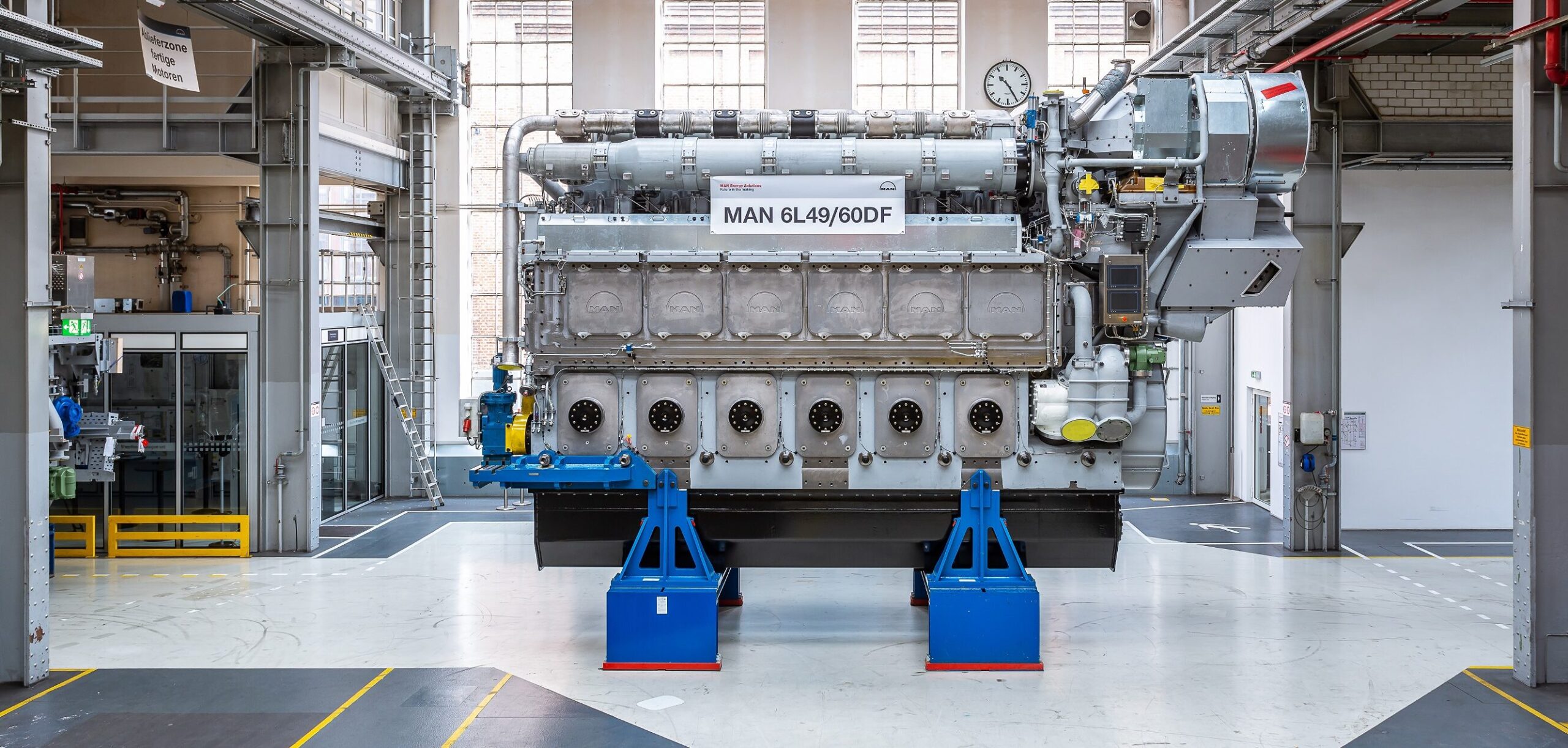
Engine Specifications
Inspector Detail
✓ verified
▸
Designation decoded
7 stands for 7 cylinders, L for Long-Stroke, 70 for 700 mm bore, MC-C for the MAN B&W MC Compact series, 8 for Mark 8.
Background
The L70MC-C8 is the Long-Stroke variant of the 70-class bore in the MC/MC-C platform. With a more moderate S/B ratio than the S variant, it suits applications with somewhat higher speeds. Typically used in Panamax bulkers and medium-sized tankers. Mark 8 as the final conventional generation.
Calculated metrics
Inspector checklist
- Cylinder liners: S/B ratio 3.24 — more moderate lateral forces than the S variant, but still document wear patterns on the thrust and anti-thrust sides
- Piston ring condition: measure butt clearance and wear height, check chrome layer for chipping
- Piston crown: check for cracks and combustion residue, especially at the ring groove edges
- Crosshead guide: document wear pattern, measure clearance
- Monitor stuffing box drainage, check sealing rings for even wear
- Measure piston rod deflection at every docking
- Check camshaft drive and chain tension
- Exhaust valve hydraulics: check pressure and valve lift
- Fuel injection pumps: verify timing and nozzle opening pressure
- Scavenge air box inspection for oil and water accumulation
- Air cooler cleaning condition and differential pressure
- Exhaust compensators and ducts for cracks
- Check cylinder cover gaskets for blow-by
- Exhaust valve seat: check grinding pattern and contact pattern
- Scavenge port edges and liner ports for deposits
Logbook reference values
| Parameter | Expected | Deviation means |
|---|---|---|
| Exhaust gas temperature after cylinder | 340-410 °C at MCR | Spread >20 °C → injection/compression problem |
| Scavenge air pressure | 2.8-3.5 bar | Drop indicates turbocharger or cooler problems |
| Pmax | Cylinder balance ±3 bar | Deviation → check injection timing |
| Cooling water temperature | 80-85 °C | Single-cylinder deviation >5 °C → check cooling |
| Lube oil pressure before engine | 3.5-4.5 bar | Pressure drop → check filter or pump |
Common Failure Modes
Expert tips
- 💡 The L variant has a more moderate S/B ratio (3.24) than the S70 — this means fewer lateral pressure problems, but higher mean piston speed at the same rpm. Watch thermal loading of the piston crown
- 💡 At the 700 bore, cylinder lubrication via quills is critical — check each quill individually for flow during inspection, blocked quills are common
- 💡 MC-C chain drive: measure not only elongation but also check the guide rails in the chain box for wear
Related components
Classification & regulatory
IMO Tier I compliant. For Tier II, adjustments to the injection system and possibly turbocharger matching are required. VLSFO or scrubber mandatory for ECA operation.
Reference content for inspector orientation. Always verify against manufacturer's manual, latest service letters and class society requirements.
Other Cylinder Configurations 50
Components & Design
Component data being added…
Technical Data
🤖 Ask about this model
One free question — answered like a marine engineer. No account needed.
Suppliers & Spare Parts
Direct links to manufacturer, datasheet, spare-parts portal and dealers — request access below.
📄 Request sourcing links & documentsCases, daily reports, timesheets and AI troubleshooting in the OceanSphere Marine app — free for 14 days.
Start free trial →Find manufacturers, repair shops and spare-part dealers in the Maritime Network — our global company directory.
Maritime Network →Manuals
-
operating
MAN B&W MC/MC-C Engine Operating Manual (OM-MC-C)MAN Energy Solutions
-
maintenance
MAN B&W MC/MC-C Maintenance Manual (MM-MC-C)MAN Energy Solutions
-
spare_parts
MAN B&W MC/MC-C Illustrated Parts Catalogue (IPC-MC-C)MAN Energy Solutions
-
project_guide
MAN B&W Project Guide MC/MC-C (PG-MC-C)MAN Energy Solutions