OceanSphere
Engines

Power Cable (3.6/6 kV)

medium 200 / 200 models (Inspector)

Rated 3.6/6 kV, this cable feeds high-voltage generators, bow thrusters and large propulsion motors where low-voltage conductors would need impractical cross-sections; its insulation and screening are built for continuous partial-discharge-free service, not just for a higher voltage number.

Read more — Power Cable (3.6/6 kV) explained

What sets 3.6/6 kV cable apart

Standard 0.6/1 kV shipboard cable becomes impractical once a consumer draws real power over any distance: the conductor cross-section needed to keep voltage drop and I²R losses within limits grows too large to bend around a cable tray. Stepping the system voltage up to 3.3 kV or 6.6 kV (the cable itself is rated 3.6/6 kV, meaning 3.6 kV phase-to-earth and 6 kV phase-to-phase) lets the same power flow through a fraction of the copper. This is why bow thrusters, large propulsion motors and generators above roughly 1-2 MW are wired at medium voltage while lighting and small motors stay on the low-voltage system.
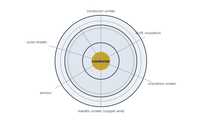
3.6/6 kV power cable cross-section
Cross-section of a 3.6/6 kV shipboard power cable showing, from the centre outward, the stranded conductor, conductor screen, XLPE insulation, insulation screen, metallic screen, armour and outer sheath.

The cable is not simply a low-voltage cable with thicker insulation. At medium voltage the electric field concentrates at any irregularity in the insulation surface, and a void or a sharp conductor edge can trigger partial discharge that erodes the insulation from the inside over years. Marine MV cable construction exists specifically to control that field.

Main components

Conductor

Stranded copper, with a semiconducting layer extruded directly over it to eliminate air gaps and even out the field at the conductor surface.

Insulation

Cross-linked polyethylene (XLPE) or ethylene propylene rubber (EPR) is standard for marine MV cable; EPR tolerates more flexing and is common where the cable sees vibration or repeated movement, XLPE gives a slightly better electrical loss figure.

Insulation screen and metallic screen

A semiconducting layer over the insulation, followed by a copper wire or tape screen, confines the electric field inside the cable and provides the earth-fault return path. This screen must be earthed correctly at both ends, or induced sheath currents become a shock and fire risk.

Bedding, armour and outer sheath

A halogen-free, flame-retardant outer sheath is standard for shipboard use. Armour, where fitted, protects against mechanical damage in exposed runs.

Selection and sizing

  • Voltage rating matched to the ship's MV system, commonly 3.3 kV or 6.6 kV nominal, with the cable rated 3.6/6 kV or 6/10 kV to give insulation margin.
  • Continuous current rating, derated for grouping with other cables in the same tray and for the ambient temperature of the space.
  • Short-circuit withstand of conductor and screen, checked against the fault current and clearing time of the protective relay.
  • Flexibility class where the run crosses a mechanical connection, for example into a thruster room.
  • Fire performance: flame-retardant to the applicable bunched-cable test as a minimum, low smoke and halogen-free for accommodation and escape route runs.

Regulations and class

SOLAS Ch. II-1 sets the general requirement for electrical installations and cable fire protection; class rules, built on the IEC 60092 series for shipboard cable construction and testing, add the detailed construction, type-approval and routing requirements. MV cable runs additionally need segregation from other services and, per class rules, physical separation or barriers where they pass through machinery spaces, since a MV fault carries far more energy into an arc than a low-voltage one. Periodic insulation resistance testing, and on larger installations partial-discharge testing, are typically required at survey intervals set by class.

Typical faults

FaultCauseConsequence
Partial discharge damageVoids or contamination at the conductor or insulation screen introduced during terminationSlow insulation erosion, eventual flashover, often years after installation
Screen overheatingScreen earthed without accounting for induced circulating currentLocal heating, accelerated ageing of the adjacent insulation
Water treeingMoisture ingress through a damaged sheath into XLPE insulationProgressive dielectric weakening, eventual breakdown under a switching surge
Termination flashoverIncorrect stress-cone or heat-shrink termination for the voltage classImmediate fault, often at first energisation or during a switching transient

What to look for in a supplier

  • Type approval from a recognised classification society for the specific construction and voltage class ordered, not just a general marine cable certificate.
  • Factory partial-discharge test records for the actual production batch, not a type-test report alone.
  • Documented compatibility between the cable and the termination/jointing kits it will be installed with; mismatched MV systems are a common site-installation failure.
  • Experience with the specific fire-performance standard called up for the installation.

Treat MV cable terminations as the highest-risk step in the whole installation: a rushed stress-cone job is invisible from the outside and often does not fail until the cable has been in service for months.
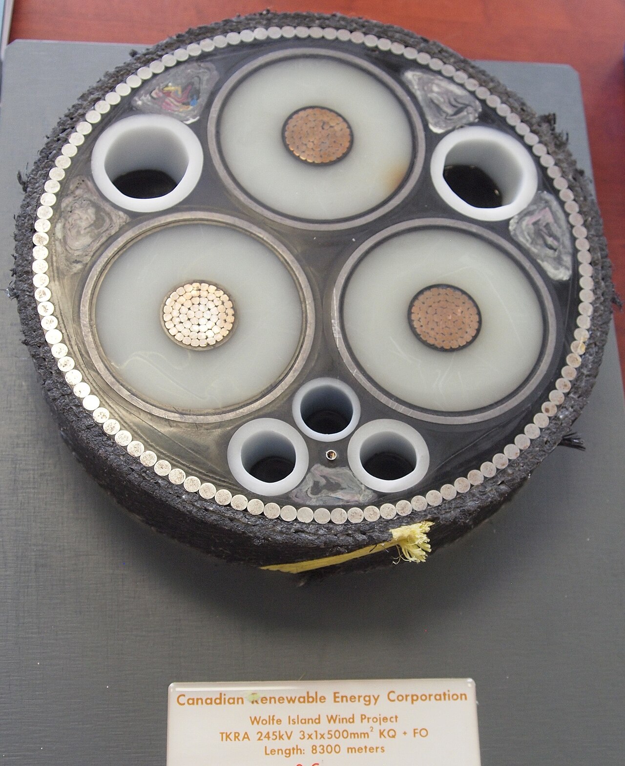
Submarine power cable
Submarine power cable. Photo: Z22, CC BY-SA 3.0, via Wikimedia Commons
Inspector Mode Show All 200 / 200 with inspector value

10 manufacturers · 200 models

Draka/Prysmian

20
LFHÖF-MV 1Cx25mm2 3.6/6kV unverified
Cross Section (mm²)
25
Voltage Class
3.6/6kV
Cores
1
Material
Cu
Insulation
XLPE
Fire Rating
IEC60332-1
Halogen-Free
nein
Common Failures & Inspection Points
  • Mechanical damage, crushing or excessive bending damages insulation and causes earth faults, conductor failure or intermittent circuits
  • Loose or corroded terminations create resistance heating and cause voltage drop, discoloration or intermittent signals
  • Water ingress through damaged sheaths or glands reduces insulation integrity and causes earth-fault alarms or unreliable operation
  • Heat, oil or chemical exposure degrades insulation and causes cracking, swelling or loss of dielectric integrity
  • Poor screening, bonding or separation on signal cables introduces electrical noise and causes unstable instrumentation or communication data
Service: Inspect accessible cable runs, supports, penetrations, glands, terminations and signs of heat, oil or mechanical damage. Check insulation condition and termination integrity using an approved test method appropriate to the circuit. Maintain fire stopping, segregation and shielding arrangements at penetrations and terminations. Refer to the cable and connected-equipment documentation for the exact figure for test voltage, bend radius and termination requirements.
Spare Parts: Carry approved glands, lugs, ferrules, heat-shrink or jointing materials and representative replacement cable for critical circuits where vessel practice requires it.
Use Cases: Electrical power distribution, motor feeders, control, instrumentation, communication and safety-system wiring.
LFHÖF-MV 3Cx25mm2 3.6/6kV unverified
Cross Section (mm²)
25
Voltage Class
3.6/6kV
Cores
3
Material
Cu
Insulation
XLPE
Fire Rating
IEC60332-1
Halogen-Free
nein
Common Failures & Inspection Points
  • Mechanical damage, crushing or excessive bending damages insulation and causes earth faults, conductor failure or intermittent circuits
  • Loose or corroded terminations create resistance heating and cause voltage drop, discoloration or intermittent signals
  • Water ingress through damaged sheaths or glands reduces insulation integrity and causes earth-fault alarms or unreliable operation
  • Heat, oil or chemical exposure degrades insulation and causes cracking, swelling or loss of dielectric integrity
  • Poor screening, bonding or separation on signal cables introduces electrical noise and causes unstable instrumentation or communication data
Service: Inspect accessible cable runs, supports, penetrations, glands, terminations and signs of heat, oil or mechanical damage. Check insulation condition and termination integrity using an approved test method appropriate to the circuit. Maintain fire stopping, segregation and shielding arrangements at penetrations and terminations. Refer to the cable and connected-equipment documentation for the exact figure for test voltage, bend radius and termination requirements.
Spare Parts: Carry approved glands, lugs, ferrules, heat-shrink or jointing materials and representative replacement cable for critical circuits where vessel practice requires it.
Use Cases: Electrical power distribution, motor feeders, control, instrumentation, communication and safety-system wiring.
LFHÖF-MV 1Cx35mm2 3.6/6kV unverified
Cross Section (mm²)
35
Voltage Class
3.6/6kV
Cores
1
Material
Cu
Insulation
XLPE
Fire Rating
IEC60332-1
Halogen-Free
nein
Common Failures & Inspection Points
  • Mechanical damage, crushing or excessive bending damages insulation and causes earth faults, conductor failure or intermittent circuits
  • Loose or corroded terminations create resistance heating and cause voltage drop, discoloration or intermittent signals
  • Water ingress through damaged sheaths or glands reduces insulation integrity and causes earth-fault alarms or unreliable operation
  • Heat, oil or chemical exposure degrades insulation and causes cracking, swelling or loss of dielectric integrity
  • Poor screening, bonding or separation on signal cables introduces electrical noise and causes unstable instrumentation or communication data
Service: Inspect accessible cable runs, supports, penetrations, glands, terminations and signs of heat, oil or mechanical damage. Check insulation condition and termination integrity using an approved test method appropriate to the circuit. Maintain fire stopping, segregation and shielding arrangements at penetrations and terminations. Refer to the cable and connected-equipment documentation for the exact figure for test voltage, bend radius and termination requirements.
Spare Parts: Carry approved glands, lugs, ferrules, heat-shrink or jointing materials and representative replacement cable for critical circuits where vessel practice requires it.
Use Cases: Electrical power distribution, motor feeders, control, instrumentation, communication and safety-system wiring.
LFHÖF-MV 3Cx35mm2 3.6/6kV unverified
Cross Section (mm²)
35
Voltage Class
3.6/6kV
Cores
3
Material
Cu
Insulation
XLPE
Fire Rating
IEC60332-1
Halogen-Free
nein
Common Failures & Inspection Points
  • Mechanical damage, crushing or excessive bending damages insulation and causes earth faults, conductor failure or intermittent circuits
  • Loose or corroded terminations create resistance heating and cause voltage drop, discoloration or intermittent signals
  • Water ingress through damaged sheaths or glands reduces insulation integrity and causes earth-fault alarms or unreliable operation
  • Heat, oil or chemical exposure degrades insulation and causes cracking, swelling or loss of dielectric integrity
  • Poor screening, bonding or separation on signal cables introduces electrical noise and causes unstable instrumentation or communication data
Service: Inspect accessible cable runs, supports, penetrations, glands, terminations and signs of heat, oil or mechanical damage. Check insulation condition and termination integrity using an approved test method appropriate to the circuit. Maintain fire stopping, segregation and shielding arrangements at penetrations and terminations. Refer to the cable and connected-equipment documentation for the exact figure for test voltage, bend radius and termination requirements.
Spare Parts: Carry approved glands, lugs, ferrules, heat-shrink or jointing materials and representative replacement cable for critical circuits where vessel practice requires it.
Use Cases: Electrical power distribution, motor feeders, control, instrumentation, communication and safety-system wiring.
LFHÖF-MV 1Cx50mm2 3.6/6kV unverified
Cross Section (mm²)
50
Voltage Class
3.6/6kV
Cores
1
Material
Cu
Insulation
XLPE
Fire Rating
IEC60332-1
Halogen-Free
nein
Common Failures & Inspection Points
  • Mechanical damage, crushing or excessive bending damages insulation and causes earth faults, conductor failure or intermittent circuits
  • Loose or corroded terminations create resistance heating and cause voltage drop, discoloration or intermittent signals
  • Water ingress through damaged sheaths or glands reduces insulation integrity and causes earth-fault alarms or unreliable operation
  • Heat, oil or chemical exposure degrades insulation and causes cracking, swelling or loss of dielectric integrity
  • Poor screening, bonding or separation on signal cables introduces electrical noise and causes unstable instrumentation or communication data
Service: Inspect accessible cable runs, supports, penetrations, glands, terminations and signs of heat, oil or mechanical damage. Check insulation condition and termination integrity using an approved test method appropriate to the circuit. Maintain fire stopping, segregation and shielding arrangements at penetrations and terminations. Refer to the cable and connected-equipment documentation for the exact figure for test voltage, bend radius and termination requirements.
Spare Parts: Carry approved glands, lugs, ferrules, heat-shrink or jointing materials and representative replacement cable for critical circuits where vessel practice requires it.
Use Cases: Electrical power distribution, motor feeders, control, instrumentation, communication and safety-system wiring.
LFHÖF-MV 3Cx50mm2 3.6/6kV unverified
Cross Section (mm²)
50
Voltage Class
3.6/6kV
Cores
3
Material
Cu
Insulation
XLPE
Fire Rating
IEC60332-1
Halogen-Free
nein
Common Failures & Inspection Points
  • Mechanical damage, crushing or excessive bending damages insulation and causes earth faults, conductor failure or intermittent circuits
  • Loose or corroded terminations create resistance heating and cause voltage drop, discoloration or intermittent signals
  • Water ingress through damaged sheaths or glands reduces insulation integrity and causes earth-fault alarms or unreliable operation
  • Heat, oil or chemical exposure degrades insulation and causes cracking, swelling or loss of dielectric integrity
  • Poor screening, bonding or separation on signal cables introduces electrical noise and causes unstable instrumentation or communication data
Service: Inspect accessible cable runs, supports, penetrations, glands, terminations and signs of heat, oil or mechanical damage. Check insulation condition and termination integrity using an approved test method appropriate to the circuit. Maintain fire stopping, segregation and shielding arrangements at penetrations and terminations. Refer to the cable and connected-equipment documentation for the exact figure for test voltage, bend radius and termination requirements.
Spare Parts: Carry approved glands, lugs, ferrules, heat-shrink or jointing materials and representative replacement cable for critical circuits where vessel practice requires it.
Use Cases: Electrical power distribution, motor feeders, control, instrumentation, communication and safety-system wiring.
LFHÖF-MV 1Cx70mm2 3.6/6kV unverified
Cross Section (mm²)
70
Voltage Class
3.6/6kV
Cores
1
Material
Cu
Insulation
XLPE
Fire Rating
IEC60332-1
Halogen-Free
nein
Common Failures & Inspection Points
  • Mechanical damage, crushing or excessive bending damages insulation and causes earth faults, conductor failure or intermittent circuits
  • Loose or corroded terminations create resistance heating and cause voltage drop, discoloration or intermittent signals
  • Water ingress through damaged sheaths or glands reduces insulation integrity and causes earth-fault alarms or unreliable operation
  • Heat, oil or chemical exposure degrades insulation and causes cracking, swelling or loss of dielectric integrity
  • Poor screening, bonding or separation on signal cables introduces electrical noise and causes unstable instrumentation or communication data
Service: Inspect accessible cable runs, supports, penetrations, glands, terminations and signs of heat, oil or mechanical damage. Check insulation condition and termination integrity using an approved test method appropriate to the circuit. Maintain fire stopping, segregation and shielding arrangements at penetrations and terminations. Refer to the cable and connected-equipment documentation for the exact figure for test voltage, bend radius and termination requirements.
Spare Parts: Carry approved glands, lugs, ferrules, heat-shrink or jointing materials and representative replacement cable for critical circuits where vessel practice requires it.
Use Cases: Electrical power distribution, motor feeders, control, instrumentation, communication and safety-system wiring.
LFHÖF-MV 3Cx70mm2 3.6/6kV unverified
Cross Section (mm²)
70
Voltage Class
3.6/6kV
Cores
3
Material
Cu
Insulation
XLPE
Fire Rating
IEC60332-1
Halogen-Free
nein
Common Failures & Inspection Points
  • Mechanical damage, crushing or excessive bending damages insulation and causes earth faults, conductor failure or intermittent circuits
  • Loose or corroded terminations create resistance heating and cause voltage drop, discoloration or intermittent signals
  • Water ingress through damaged sheaths or glands reduces insulation integrity and causes earth-fault alarms or unreliable operation
  • Heat, oil or chemical exposure degrades insulation and causes cracking, swelling or loss of dielectric integrity
  • Poor screening, bonding or separation on signal cables introduces electrical noise and causes unstable instrumentation or communication data
Service: Inspect accessible cable runs, supports, penetrations, glands, terminations and signs of heat, oil or mechanical damage. Check insulation condition and termination integrity using an approved test method appropriate to the circuit. Maintain fire stopping, segregation and shielding arrangements at penetrations and terminations. Refer to the cable and connected-equipment documentation for the exact figure for test voltage, bend radius and termination requirements.
Spare Parts: Carry approved glands, lugs, ferrules, heat-shrink or jointing materials and representative replacement cable for critical circuits where vessel practice requires it.
Use Cases: Electrical power distribution, motor feeders, control, instrumentation, communication and safety-system wiring.
LFHÖF-MV 1Cx95mm2 3.6/6kV unverified
Cross Section (mm²)
95
Voltage Class
3.6/6kV
Cores
1
Material
Cu
Insulation
XLPE
Fire Rating
IEC60332-1
Halogen-Free
nein
Common Failures & Inspection Points
  • Mechanical damage, crushing or excessive bending damages insulation and causes earth faults, conductor failure or intermittent circuits
  • Loose or corroded terminations create resistance heating and cause voltage drop, discoloration or intermittent signals
  • Water ingress through damaged sheaths or glands reduces insulation integrity and causes earth-fault alarms or unreliable operation
  • Heat, oil or chemical exposure degrades insulation and causes cracking, swelling or loss of dielectric integrity
  • Poor screening, bonding or separation on signal cables introduces electrical noise and causes unstable instrumentation or communication data
Service: Inspect accessible cable runs, supports, penetrations, glands, terminations and signs of heat, oil or mechanical damage. Check insulation condition and termination integrity using an approved test method appropriate to the circuit. Maintain fire stopping, segregation and shielding arrangements at penetrations and terminations. Refer to the cable and connected-equipment documentation for the exact figure for test voltage, bend radius and termination requirements.
Spare Parts: Carry approved glands, lugs, ferrules, heat-shrink or jointing materials and representative replacement cable for critical circuits where vessel practice requires it.
Use Cases: Electrical power distribution, motor feeders, control, instrumentation, communication and safety-system wiring.
LFHÖF-MV 3Cx95mm2 3.6/6kV unverified
Cross Section (mm²)
95
Voltage Class
3.6/6kV
Cores
3
Material
Cu
Insulation
XLPE
Fire Rating
IEC60332-1
Halogen-Free
nein
Common Failures & Inspection Points
  • Mechanical damage, crushing or excessive bending damages insulation and causes earth faults, conductor failure or intermittent circuits
  • Loose or corroded terminations create resistance heating and cause voltage drop, discoloration or intermittent signals
  • Water ingress through damaged sheaths or glands reduces insulation integrity and causes earth-fault alarms or unreliable operation
  • Heat, oil or chemical exposure degrades insulation and causes cracking, swelling or loss of dielectric integrity
  • Poor screening, bonding or separation on signal cables introduces electrical noise and causes unstable instrumentation or communication data
Service: Inspect accessible cable runs, supports, penetrations, glands, terminations and signs of heat, oil or mechanical damage. Check insulation condition and termination integrity using an approved test method appropriate to the circuit. Maintain fire stopping, segregation and shielding arrangements at penetrations and terminations. Refer to the cable and connected-equipment documentation for the exact figure for test voltage, bend radius and termination requirements.
Spare Parts: Carry approved glands, lugs, ferrules, heat-shrink or jointing materials and representative replacement cable for critical circuits where vessel practice requires it.
Use Cases: Electrical power distribution, motor feeders, control, instrumentation, communication and safety-system wiring.
LFHÖF-MV 1Cx120mm2 3.6/6kV unverified
Cross Section (mm²)
120
Voltage Class
3.6/6kV
Cores
1
Material
Cu
Insulation
XLPE
Fire Rating
IEC60332-1
Halogen-Free
nein
Common Failures & Inspection Points
  • Insulation deterioration caused by heat, oil, ultraviolet exposure, moisture or age, resulting in low insulation resistance, earth faults or intermittent trips
  • Termination overheating caused by loose lugs, corrosion or poor crimping, resulting in discoloration, odor or localized temperature rise
  • Mechanical damage caused by chafing, crushing, excessive bend or unsupported routing, resulting in exposed armor, sheath damage or conductor failure
  • Water ingress caused by damaged glands, sheath or deck penetrations, resulting in corrosion, leakage current or communication faults
  • Screening, grounding or fire-seal deficiency caused by incorrect installation or maintenance, resulting in interference, poor fault protection or reduced fire integrity
Service: Inspect visible cable runs, supports, glands, terminations, penetrations and fire stops for damage, corrosion, overheating and unauthorized modifications. Maintain bend radius and support without imposing strain on equipment terminals. Check insulation resistance or continuity using procedures suitable for connected equipment and isolate sensitive electronics when required. Inspect cable glands and deck penetrations for water ingress and verify screens and armor are terminated according to the approved design. Replace damaged cable with an approved equivalent rather than patching critical insulation casually. Refer to the manufacturer documentation for the exact figure for conductor ratings, bend radius and test limits.
Spare Parts: Keep suitable lengths of approved cable for critical services together with glands, lugs, ferrules, heat-shrink, identification materials and certified fire-stop products appropriate to the installation. Communication and fire-resistant cable replacements must preserve required screening and approval. Verify voltage, conductor size and material before use.
Use Cases: Power distribution, motor feeders, control circuits, instrumentation, safety systems and communications throughout merchant ships and offshore installations.
LFHÖF-MV 3Cx120mm2 3.6/6kV unverified
Cross Section (mm²)
120
Voltage Class
3.6/6kV
Cores
3
Material
Cu
Insulation
XLPE
Fire Rating
IEC60332-1
Halogen-Free
nein
Common Failures & Inspection Points
  • Insulation deterioration caused by heat, oil, ultraviolet exposure, moisture or age, resulting in low insulation resistance, earth faults or intermittent trips
  • Termination overheating caused by loose lugs, corrosion or poor crimping, resulting in discoloration, odor or localized temperature rise
  • Mechanical damage caused by chafing, crushing, excessive bend or unsupported routing, resulting in exposed armor, sheath damage or conductor failure
  • Water ingress caused by damaged glands, sheath or deck penetrations, resulting in corrosion, leakage current or communication faults
  • Screening, grounding or fire-seal deficiency caused by incorrect installation or maintenance, resulting in interference, poor fault protection or reduced fire integrity
Service: Inspect visible cable runs, supports, glands, terminations, penetrations and fire stops for damage, corrosion, overheating and unauthorized modifications. Maintain bend radius and support without imposing strain on equipment terminals. Check insulation resistance or continuity using procedures suitable for connected equipment and isolate sensitive electronics when required. Inspect cable glands and deck penetrations for water ingress and verify screens and armor are terminated according to the approved design. Replace damaged cable with an approved equivalent rather than patching critical insulation casually. Refer to the manufacturer documentation for the exact figure for conductor ratings, bend radius and test limits.
Spare Parts: Keep suitable lengths of approved cable for critical services together with glands, lugs, ferrules, heat-shrink, identification materials and certified fire-stop products appropriate to the installation. Communication and fire-resistant cable replacements must preserve required screening and approval. Verify voltage, conductor size and material before use.
Use Cases: Power distribution, motor feeders, control circuits, instrumentation, safety systems and communications throughout merchant ships and offshore installations.
LFHÖF-MV 1Cx150mm2 3.6/6kV unverified
Cross Section (mm²)
150
Voltage Class
3.6/6kV
Cores
1
Material
Cu
Insulation
XLPE
Fire Rating
IEC60332-1
Halogen-Free
nein
Common Failures & Inspection Points
  • Insulation deterioration caused by heat, oil, ultraviolet exposure, moisture or age, resulting in low insulation resistance, earth faults or intermittent trips
  • Termination overheating caused by loose lugs, corrosion or poor crimping, resulting in discoloration, odor or localized temperature rise
  • Mechanical damage caused by chafing, crushing, excessive bend or unsupported routing, resulting in exposed armor, sheath damage or conductor failure
  • Water ingress caused by damaged glands, sheath or deck penetrations, resulting in corrosion, leakage current or communication faults
  • Screening, grounding or fire-seal deficiency caused by incorrect installation or maintenance, resulting in interference, poor fault protection or reduced fire integrity
Service: Inspect visible cable runs, supports, glands, terminations, penetrations and fire stops for damage, corrosion, overheating and unauthorized modifications. Maintain bend radius and support without imposing strain on equipment terminals. Check insulation resistance or continuity using procedures suitable for connected equipment and isolate sensitive electronics when required. Inspect cable glands and deck penetrations for water ingress and verify screens and armor are terminated according to the approved design. Replace damaged cable with an approved equivalent rather than patching critical insulation casually. Refer to the manufacturer documentation for the exact figure for conductor ratings, bend radius and test limits.
Spare Parts: Keep suitable lengths of approved cable for critical services together with glands, lugs, ferrules, heat-shrink, identification materials and certified fire-stop products appropriate to the installation. Communication and fire-resistant cable replacements must preserve required screening and approval. Verify voltage, conductor size and material before use.
Use Cases: Power distribution, motor feeders, control circuits, instrumentation, safety systems and communications throughout merchant ships and offshore installations.
LFHÖF-MV 3Cx150mm2 3.6/6kV unverified
Cross Section (mm²)
150
Voltage Class
3.6/6kV
Cores
3
Material
Cu
Insulation
XLPE
Fire Rating
IEC60332-1
Halogen-Free
nein
Common Failures & Inspection Points
  • Insulation deterioration caused by heat, oil, ultraviolet exposure, moisture or age, resulting in low insulation resistance, earth faults or intermittent trips
  • Termination overheating caused by loose lugs, corrosion or poor crimping, resulting in discoloration, odor or localized temperature rise
  • Mechanical damage caused by chafing, crushing, excessive bend or unsupported routing, resulting in exposed armor, sheath damage or conductor failure
  • Water ingress caused by damaged glands, sheath or deck penetrations, resulting in corrosion, leakage current or communication faults
  • Screening, grounding or fire-seal deficiency caused by incorrect installation or maintenance, resulting in interference, poor fault protection or reduced fire integrity
Service: Inspect visible cable runs, supports, glands, terminations, penetrations and fire stops for damage, corrosion, overheating and unauthorized modifications. Maintain bend radius and support without imposing strain on equipment terminals. Check insulation resistance or continuity using procedures suitable for connected equipment and isolate sensitive electronics when required. Inspect cable glands and deck penetrations for water ingress and verify screens and armor are terminated according to the approved design. Replace damaged cable with an approved equivalent rather than patching critical insulation casually. Refer to the manufacturer documentation for the exact figure for conductor ratings, bend radius and test limits.
Spare Parts: Keep suitable lengths of approved cable for critical services together with glands, lugs, ferrules, heat-shrink, identification materials and certified fire-stop products appropriate to the installation. Communication and fire-resistant cable replacements must preserve required screening and approval. Verify voltage, conductor size and material before use.
Use Cases: Power distribution, motor feeders, control circuits, instrumentation, safety systems and communications throughout merchant ships and offshore installations.
LFHÖF-MV 1Cx185mm2 3.6/6kV unverified
Cross Section (mm²)
185
Voltage Class
3.6/6kV
Cores
1
Material
Cu
Insulation
XLPE
Fire Rating
IEC60332-1
Halogen-Free
nein
Common Failures & Inspection Points
  • Insulation deterioration caused by heat, oil, ultraviolet exposure, moisture or age, resulting in low insulation resistance, earth faults or intermittent trips
  • Termination overheating caused by loose lugs, corrosion or poor crimping, resulting in discoloration, odor or localized temperature rise
  • Mechanical damage caused by chafing, crushing, excessive bend or unsupported routing, resulting in exposed armor, sheath damage or conductor failure
  • Water ingress caused by damaged glands, sheath or deck penetrations, resulting in corrosion, leakage current or communication faults
  • Screening, grounding or fire-seal deficiency caused by incorrect installation or maintenance, resulting in interference, poor fault protection or reduced fire integrity
Service: Inspect visible cable runs, supports, glands, terminations, penetrations and fire stops for damage, corrosion, overheating and unauthorized modifications. Maintain bend radius and support without imposing strain on equipment terminals. Check insulation resistance or continuity using procedures suitable for connected equipment and isolate sensitive electronics when required. Inspect cable glands and deck penetrations for water ingress and verify screens and armor are terminated according to the approved design. Replace damaged cable with an approved equivalent rather than patching critical insulation casually. Refer to the manufacturer documentation for the exact figure for conductor ratings, bend radius and test limits.
Spare Parts: Keep suitable lengths of approved cable for critical services together with glands, lugs, ferrules, heat-shrink, identification materials and certified fire-stop products appropriate to the installation. Communication and fire-resistant cable replacements must preserve required screening and approval. Verify voltage, conductor size and material before use.
Use Cases: Power distribution, motor feeders, control circuits, instrumentation, safety systems and communications throughout merchant ships and offshore installations.
LFHÖF-MV 3Cx185mm2 3.6/6kV unverified
Cross Section (mm²)
185
Voltage Class
3.6/6kV
Cores
3
Material
Cu
Insulation
XLPE
Fire Rating
IEC60332-1
Halogen-Free
nein
Common Failures & Inspection Points
  • Insulation deterioration caused by heat, oil, ultraviolet exposure, moisture or age, resulting in low insulation resistance, earth faults or intermittent trips
  • Termination overheating caused by loose lugs, corrosion or poor crimping, resulting in discoloration, odor or localized temperature rise
  • Mechanical damage caused by chafing, crushing, excessive bend or unsupported routing, resulting in exposed armor, sheath damage or conductor failure
  • Water ingress caused by damaged glands, sheath or deck penetrations, resulting in corrosion, leakage current or communication faults
  • Screening, grounding or fire-seal deficiency caused by incorrect installation or maintenance, resulting in interference, poor fault protection or reduced fire integrity
Service: Inspect visible cable runs, supports, glands, terminations, penetrations and fire stops for damage, corrosion, overheating and unauthorized modifications. Maintain bend radius and support without imposing strain on equipment terminals. Check insulation resistance or continuity using procedures suitable for connected equipment and isolate sensitive electronics when required. Inspect cable glands and deck penetrations for water ingress and verify screens and armor are terminated according to the approved design. Replace damaged cable with an approved equivalent rather than patching critical insulation casually. Refer to the manufacturer documentation for the exact figure for conductor ratings, bend radius and test limits.
Spare Parts: Keep suitable lengths of approved cable for critical services together with glands, lugs, ferrules, heat-shrink, identification materials and certified fire-stop products appropriate to the installation. Communication and fire-resistant cable replacements must preserve required screening and approval. Verify voltage, conductor size and material before use.
Use Cases: Power distribution, motor feeders, control circuits, instrumentation, safety systems and communications throughout merchant ships and offshore installations.
LFHÖF-MV 1Cx240mm2 3.6/6kV unverified
Cross Section (mm²)
240
Voltage Class
3.6/6kV
Cores
1
Material
Cu
Insulation
XLPE
Fire Rating
IEC60332-1
Halogen-Free
nein
Common Failures & Inspection Points
  • Insulation deterioration caused by heat, oil, ultraviolet exposure, moisture or age, resulting in low insulation resistance, earth faults or intermittent trips
  • Termination overheating caused by loose lugs, corrosion or poor crimping, resulting in discoloration, odor or localized temperature rise
  • Mechanical damage caused by chafing, crushing, excessive bend or unsupported routing, resulting in exposed armor, sheath damage or conductor failure
  • Water ingress caused by damaged glands, sheath or deck penetrations, resulting in corrosion, leakage current or communication faults
  • Screening, grounding or fire-seal deficiency caused by incorrect installation or maintenance, resulting in interference, poor fault protection or reduced fire integrity
Service: Inspect visible cable runs, supports, glands, terminations, penetrations and fire stops for damage, corrosion, overheating and unauthorized modifications. Maintain bend radius and support without imposing strain on equipment terminals. Check insulation resistance or continuity using procedures suitable for connected equipment and isolate sensitive electronics when required. Inspect cable glands and deck penetrations for water ingress and verify screens and armor are terminated according to the approved design. Replace damaged cable with an approved equivalent rather than patching critical insulation casually. Refer to the manufacturer documentation for the exact figure for conductor ratings, bend radius and test limits.
Spare Parts: Keep suitable lengths of approved cable for critical services together with glands, lugs, ferrules, heat-shrink, identification materials and certified fire-stop products appropriate to the installation. Communication and fire-resistant cable replacements must preserve required screening and approval. Verify voltage, conductor size and material before use.
Use Cases: Power distribution, motor feeders, control circuits, instrumentation, safety systems and communications throughout merchant ships and offshore installations.
LFHÖF-MV 3Cx240mm2 3.6/6kV unverified
Cross Section (mm²)
240
Voltage Class
3.6/6kV
Cores
3
Material
Cu
Insulation
XLPE
Fire Rating
IEC60332-1
Halogen-Free
nein
Common Failures & Inspection Points
  • Insulation deterioration caused by heat, oil, ultraviolet exposure, moisture or age, resulting in low insulation resistance, earth faults or intermittent trips
  • Termination overheating caused by loose lugs, corrosion or poor crimping, resulting in discoloration, odor or localized temperature rise
  • Mechanical damage caused by chafing, crushing, excessive bend or unsupported routing, resulting in exposed armor, sheath damage or conductor failure
  • Water ingress caused by damaged glands, sheath or deck penetrations, resulting in corrosion, leakage current or communication faults
  • Screening, grounding or fire-seal deficiency caused by incorrect installation or maintenance, resulting in interference, poor fault protection or reduced fire integrity
Service: Inspect visible cable runs, supports, glands, terminations, penetrations and fire stops for damage, corrosion, overheating and unauthorized modifications. Maintain bend radius and support without imposing strain on equipment terminals. Check insulation resistance or continuity using procedures suitable for connected equipment and isolate sensitive electronics when required. Inspect cable glands and deck penetrations for water ingress and verify screens and armor are terminated according to the approved design. Replace damaged cable with an approved equivalent rather than patching critical insulation casually. Refer to the manufacturer documentation for the exact figure for conductor ratings, bend radius and test limits.
Spare Parts: Keep suitable lengths of approved cable for critical services together with glands, lugs, ferrules, heat-shrink, identification materials and certified fire-stop products appropriate to the installation. Communication and fire-resistant cable replacements must preserve required screening and approval. Verify voltage, conductor size and material before use.
Use Cases: Power distribution, motor feeders, control circuits, instrumentation, safety systems and communications throughout merchant ships and offshore installations.
LFHÖF-MV 1Cx300mm2 3.6/6kV unverified
Cross Section (mm²)
300
Voltage Class
3.6/6kV
Cores
1
Material
Cu
Insulation
XLPE
Fire Rating
IEC60332-1
Halogen-Free
nein
Common Failures & Inspection Points
  • Insulation deterioration caused by heat, oil, ultraviolet exposure, moisture or age, resulting in low insulation resistance, earth faults or intermittent trips
  • Termination overheating caused by loose lugs, corrosion or poor crimping, resulting in discoloration, odor or localized temperature rise
  • Mechanical damage caused by chafing, crushing, excessive bend or unsupported routing, resulting in exposed armor, sheath damage or conductor failure
  • Water ingress caused by damaged glands, sheath or deck penetrations, resulting in corrosion, leakage current or communication faults
  • Screening, grounding or fire-seal deficiency caused by incorrect installation or maintenance, resulting in interference, poor fault protection or reduced fire integrity
Service: Inspect visible cable runs, supports, glands, terminations, penetrations and fire stops for damage, corrosion, overheating and unauthorized modifications. Maintain bend radius and support without imposing strain on equipment terminals. Check insulation resistance or continuity using procedures suitable for connected equipment and isolate sensitive electronics when required. Inspect cable glands and deck penetrations for water ingress and verify screens and armor are terminated according to the approved design. Replace damaged cable with an approved equivalent rather than patching critical insulation casually. Refer to the manufacturer documentation for the exact figure for conductor ratings, bend radius and test limits.
Spare Parts: Keep suitable lengths of approved cable for critical services together with glands, lugs, ferrules, heat-shrink, identification materials and certified fire-stop products appropriate to the installation. Communication and fire-resistant cable replacements must preserve required screening and approval. Verify voltage, conductor size and material before use.
Use Cases: Power distribution, motor feeders, control circuits, instrumentation, safety systems and communications throughout merchant ships and offshore installations.
LFHÖF-MV 3Cx300mm2 3.6/6kV unverified
Cross Section (mm²)
300
Voltage Class
3.6/6kV
Cores
3
Material
Cu
Insulation
XLPE
Fire Rating
IEC60332-1
Halogen-Free
nein
Common Failures & Inspection Points
  • Insulation deterioration caused by heat, oil, ultraviolet exposure, moisture or age, resulting in low insulation resistance, earth faults or intermittent trips
  • Termination overheating caused by loose lugs, corrosion or poor crimping, resulting in discoloration, odor or localized temperature rise
  • Mechanical damage caused by chafing, crushing, excessive bend or unsupported routing, resulting in exposed armor, sheath damage or conductor failure
  • Water ingress caused by damaged glands, sheath or deck penetrations, resulting in corrosion, leakage current or communication faults
  • Screening, grounding or fire-seal deficiency caused by incorrect installation or maintenance, resulting in interference, poor fault protection or reduced fire integrity
Service: Inspect visible cable runs, supports, glands, terminations, penetrations and fire stops for damage, corrosion, overheating and unauthorized modifications. Maintain bend radius and support without imposing strain on equipment terminals. Check insulation resistance or continuity using procedures suitable for connected equipment and isolate sensitive electronics when required. Inspect cable glands and deck penetrations for water ingress and verify screens and armor are terminated according to the approved design. Replace damaged cable with an approved equivalent rather than patching critical insulation casually. Refer to the manufacturer documentation for the exact figure for conductor ratings, bend radius and test limits.
Spare Parts: Keep suitable lengths of approved cable for critical services together with glands, lugs, ferrules, heat-shrink, identification materials and certified fire-stop products appropriate to the installation. Communication and fire-resistant cable replacements must preserve required screening and approval. Verify voltage, conductor size and material before use.
Use Cases: Power distribution, motor feeders, control circuits, instrumentation, safety systems and communications throughout merchant ships and offshore installations.

Eland Cables

20
MGCL 1Cx25mm2 3.6/6kV unverified
Cross Section (mm²)
25
Voltage Class
3.6/6kV
Cores
1
Material
Cu
Insulation
XLPE
Fire Rating
IEC60332-1
Halogen-Free
nein
Common Failures & Inspection Points
  • Insulation damage from heat, abrasion, oil, chemicals, or mechanical impact causes earth faults, leakage current, or intermittent circuits
  • Loose or corroded terminations increase contact resistance and appear as heating, voltage drop, or unstable signals
  • Water ingress through glands, junction boxes, or damaged sheath causes corrosion, insulation deterioration, or repeated electrical faults
  • Excessive bending, unsupported runs, or vibration damages conductors or shielding and can produce intermittent open circuits
  • Fire or thermal exposure beyond the cable's design condition can degrade insulation and lead to loss of continuity or short circuit
Service: Inspect accessible routes, support spacing, bend condition, segregation, glands, penetrations, fire stops, sheath damage, terminations, earthing or shielding, and signs of overheating. Insulation and continuity testing must suit the circuit and connected equipment; refer to approved cable data for exact test voltages and installation limits.
Spare Parts: Keep approved glands, lugs, ferrules, terminals, junction-box sealing items, repair sleeves where permitted, and suitable replacement cable of the exact approved type and rating.
Use Cases: Used throughout all vessel types for power distribution, control, instrumentation, communications, safety systems, and emergency circuits.
MGCL 3Cx25mm2 3.6/6kV unverified
Cross Section (mm²)
25
Voltage Class
3.6/6kV
Cores
3
Material
Cu
Insulation
XLPE
Fire Rating
IEC60332-1
Halogen-Free
nein
Common Failures & Inspection Points
  • Insulation damage from heat, abrasion, oil, chemicals, or mechanical impact causes earth faults, leakage current, or intermittent circuits
  • Loose or corroded terminations increase contact resistance and appear as heating, voltage drop, or unstable signals
  • Water ingress through glands, junction boxes, or damaged sheath causes corrosion, insulation deterioration, or repeated electrical faults
  • Excessive bending, unsupported runs, or vibration damages conductors or shielding and can produce intermittent open circuits
  • Fire or thermal exposure beyond the cable's design condition can degrade insulation and lead to loss of continuity or short circuit
Service: Inspect accessible routes, support spacing, bend condition, segregation, glands, penetrations, fire stops, sheath damage, terminations, earthing or shielding, and signs of overheating. Insulation and continuity testing must suit the circuit and connected equipment; refer to approved cable data for exact test voltages and installation limits.
Spare Parts: Keep approved glands, lugs, ferrules, terminals, junction-box sealing items, repair sleeves where permitted, and suitable replacement cable of the exact approved type and rating.
Use Cases: Used throughout all vessel types for power distribution, control, instrumentation, communications, safety systems, and emergency circuits.
MGCL 1Cx35mm2 3.6/6kV unverified
Cross Section (mm²)
35
Voltage Class
3.6/6kV
Cores
1
Material
Cu
Insulation
XLPE
Fire Rating
IEC60332-1
Halogen-Free
nein
Common Failures & Inspection Points
  • Insulation damage from heat, abrasion, oil, chemicals, or mechanical impact causes earth faults, leakage current, or intermittent circuits
  • Loose or corroded terminations increase contact resistance and appear as heating, voltage drop, or unstable signals
  • Water ingress through glands, junction boxes, or damaged sheath causes corrosion, insulation deterioration, or repeated electrical faults
  • Excessive bending, unsupported runs, or vibration damages conductors or shielding and can produce intermittent open circuits
  • Fire or thermal exposure beyond the cable's design condition can degrade insulation and lead to loss of continuity or short circuit
Service: Inspect accessible routes, support spacing, bend condition, segregation, glands, penetrations, fire stops, sheath damage, terminations, earthing or shielding, and signs of overheating. Insulation and continuity testing must suit the circuit and connected equipment; refer to approved cable data for exact test voltages and installation limits.
Spare Parts: Keep approved glands, lugs, ferrules, terminals, junction-box sealing items, repair sleeves where permitted, and suitable replacement cable of the exact approved type and rating.
Use Cases: Used throughout all vessel types for power distribution, control, instrumentation, communications, safety systems, and emergency circuits.
MGCL 3Cx35mm2 3.6/6kV unverified
Cross Section (mm²)
35
Voltage Class
3.6/6kV
Cores
3
Material
Cu
Insulation
XLPE
Fire Rating
IEC60332-1
Halogen-Free
nein
Common Failures & Inspection Points
  • Insulation damage from heat, abrasion, oil, chemicals, or mechanical impact causes earth faults, leakage current, or intermittent circuits
  • Loose or corroded terminations increase contact resistance and appear as heating, voltage drop, or unstable signals
  • Water ingress through glands, junction boxes, or damaged sheath causes corrosion, insulation deterioration, or repeated electrical faults
  • Excessive bending, unsupported runs, or vibration damages conductors or shielding and can produce intermittent open circuits
  • Fire or thermal exposure beyond the cable's design condition can degrade insulation and lead to loss of continuity or short circuit
Service: Inspect accessible routes, support spacing, bend condition, segregation, glands, penetrations, fire stops, sheath damage, terminations, earthing or shielding, and signs of overheating. Insulation and continuity testing must suit the circuit and connected equipment; refer to approved cable data for exact test voltages and installation limits.
Spare Parts: Keep approved glands, lugs, ferrules, terminals, junction-box sealing items, repair sleeves where permitted, and suitable replacement cable of the exact approved type and rating.
Use Cases: Used throughout all vessel types for power distribution, control, instrumentation, communications, safety systems, and emergency circuits.
MGCL 1Cx50mm2 3.6/6kV unverified
Cross Section (mm²)
50
Voltage Class
3.6/6kV
Cores
1
Material
Cu
Insulation
XLPE
Fire Rating
IEC60332-1
Halogen-Free
nein
Common Failures & Inspection Points
  • Insulation damage from heat, abrasion, oil, chemicals, or mechanical impact causes earth faults, leakage current, or intermittent circuits
  • Loose or corroded terminations increase contact resistance and appear as heating, voltage drop, or unstable signals
  • Water ingress through glands, junction boxes, or damaged sheath causes corrosion, insulation deterioration, or repeated electrical faults
  • Excessive bending, unsupported runs, or vibration damages conductors or shielding and can produce intermittent open circuits
  • Fire or thermal exposure beyond the cable's design condition can degrade insulation and lead to loss of continuity or short circuit
Service: Inspect accessible routes, support spacing, bend condition, segregation, glands, penetrations, fire stops, sheath damage, terminations, earthing or shielding, and signs of overheating. Insulation and continuity testing must suit the circuit and connected equipment; refer to approved cable data for exact test voltages and installation limits.
Spare Parts: Keep approved glands, lugs, ferrules, terminals, junction-box sealing items, repair sleeves where permitted, and suitable replacement cable of the exact approved type and rating.
Use Cases: Used throughout all vessel types for power distribution, control, instrumentation, communications, safety systems, and emergency circuits.
MGCL 3Cx50mm2 3.6/6kV unverified
Cross Section (mm²)
50
Voltage Class
3.6/6kV
Cores
3
Material
Cu
Insulation
XLPE
Fire Rating
IEC60332-1
Halogen-Free
nein
Common Failures & Inspection Points
  • Insulation damage from heat, abrasion, oil, chemicals, or mechanical impact causes earth faults, leakage current, or intermittent circuits
  • Loose or corroded terminations increase contact resistance and appear as heating, voltage drop, or unstable signals
  • Water ingress through glands, junction boxes, or damaged sheath causes corrosion, insulation deterioration, or repeated electrical faults
  • Excessive bending, unsupported runs, or vibration damages conductors or shielding and can produce intermittent open circuits
  • Fire or thermal exposure beyond the cable's design condition can degrade insulation and lead to loss of continuity or short circuit
Service: Inspect accessible routes, support spacing, bend condition, segregation, glands, penetrations, fire stops, sheath damage, terminations, earthing or shielding, and signs of overheating. Insulation and continuity testing must suit the circuit and connected equipment; refer to approved cable data for exact test voltages and installation limits.
Spare Parts: Keep approved glands, lugs, ferrules, terminals, junction-box sealing items, repair sleeves where permitted, and suitable replacement cable of the exact approved type and rating.
Use Cases: Used throughout all vessel types for power distribution, control, instrumentation, communications, safety systems, and emergency circuits.
MGCL 1Cx70mm2 3.6/6kV unverified
Cross Section (mm²)
70
Voltage Class
3.6/6kV
Cores
1
Material
Cu
Insulation
XLPE
Fire Rating
IEC60332-1
Halogen-Free
nein
Common Failures & Inspection Points
  • Insulation damage from heat, abrasion, oil, chemicals, or mechanical impact causes earth faults, leakage current, or intermittent circuits
  • Loose or corroded terminations increase contact resistance and appear as heating, voltage drop, or unstable signals
  • Water ingress through glands, junction boxes, or damaged sheath causes corrosion, insulation deterioration, or repeated electrical faults
  • Excessive bending, unsupported runs, or vibration damages conductors or shielding and can produce intermittent open circuits
  • Fire or thermal exposure beyond the cable's design condition can degrade insulation and lead to loss of continuity or short circuit
Service: Inspect accessible routes, support spacing, bend condition, segregation, glands, penetrations, fire stops, sheath damage, terminations, earthing or shielding, and signs of overheating. Insulation and continuity testing must suit the circuit and connected equipment; refer to approved cable data for exact test voltages and installation limits.
Spare Parts: Keep approved glands, lugs, ferrules, terminals, junction-box sealing items, repair sleeves where permitted, and suitable replacement cable of the exact approved type and rating.
Use Cases: Used throughout all vessel types for power distribution, control, instrumentation, communications, safety systems, and emergency circuits.
MGCL 3Cx70mm2 3.6/6kV unverified
Cross Section (mm²)
70
Voltage Class
3.6/6kV
Cores
3
Material
Cu
Insulation
XLPE
Fire Rating
IEC60332-1
Halogen-Free
nein
Common Failures & Inspection Points
  • Insulation damage from heat, abrasion, oil, chemicals, or mechanical impact causes earth faults, leakage current, or intermittent circuits
  • Loose or corroded terminations increase contact resistance and appear as heating, voltage drop, or unstable signals
  • Water ingress through glands, junction boxes, or damaged sheath causes corrosion, insulation deterioration, or repeated electrical faults
  • Excessive bending, unsupported runs, or vibration damages conductors or shielding and can produce intermittent open circuits
  • Fire or thermal exposure beyond the cable's design condition can degrade insulation and lead to loss of continuity or short circuit
Service: Inspect accessible routes, support spacing, bend condition, segregation, glands, penetrations, fire stops, sheath damage, terminations, earthing or shielding, and signs of overheating. Insulation and continuity testing must suit the circuit and connected equipment; refer to approved cable data for exact test voltages and installation limits.
Spare Parts: Keep approved glands, lugs, ferrules, terminals, junction-box sealing items, repair sleeves where permitted, and suitable replacement cable of the exact approved type and rating.
Use Cases: Used throughout all vessel types for power distribution, control, instrumentation, communications, safety systems, and emergency circuits.
MGCL 1Cx95mm2 3.6/6kV unverified
Cross Section (mm²)
95
Voltage Class
3.6/6kV
Cores
1
Material
Cu
Insulation
XLPE
Fire Rating
IEC60332-1
Halogen-Free
nein
Common Failures & Inspection Points
  • Insulation damage from heat, abrasion, oil, chemicals, or mechanical impact causes earth faults, leakage current, or intermittent circuits
  • Loose or corroded terminations increase contact resistance and appear as heating, voltage drop, or unstable signals
  • Water ingress through glands, junction boxes, or damaged sheath causes corrosion, insulation deterioration, or repeated electrical faults
  • Excessive bending, unsupported runs, or vibration damages conductors or shielding and can produce intermittent open circuits
  • Fire or thermal exposure beyond the cable's design condition can degrade insulation and lead to loss of continuity or short circuit
Service: Inspect accessible routes, support spacing, bend condition, segregation, glands, penetrations, fire stops, sheath damage, terminations, earthing or shielding, and signs of overheating. Insulation and continuity testing must suit the circuit and connected equipment; refer to approved cable data for exact test voltages and installation limits.
Spare Parts: Keep approved glands, lugs, ferrules, terminals, junction-box sealing items, repair sleeves where permitted, and suitable replacement cable of the exact approved type and rating.
Use Cases: Used throughout all vessel types for power distribution, control, instrumentation, communications, safety systems, and emergency circuits.
MGCL 3Cx95mm2 3.6/6kV unverified
Cross Section (mm²)
95
Voltage Class
3.6/6kV
Cores
3
Material
Cu
Insulation
XLPE
Fire Rating
IEC60332-1
Halogen-Free
nein
Common Failures & Inspection Points
  • Insulation damage from heat, abrasion, oil, chemicals, or mechanical impact causes earth faults, leakage current, or intermittent circuits
  • Loose or corroded terminations increase contact resistance and appear as heating, voltage drop, or unstable signals
  • Water ingress through glands, junction boxes, or damaged sheath causes corrosion, insulation deterioration, or repeated electrical faults
  • Excessive bending, unsupported runs, or vibration damages conductors or shielding and can produce intermittent open circuits
  • Fire or thermal exposure beyond the cable's design condition can degrade insulation and lead to loss of continuity or short circuit
Service: Inspect accessible routes, support spacing, bend condition, segregation, glands, penetrations, fire stops, sheath damage, terminations, earthing or shielding, and signs of overheating. Insulation and continuity testing must suit the circuit and connected equipment; refer to approved cable data for exact test voltages and installation limits.
Spare Parts: Keep approved glands, lugs, ferrules, terminals, junction-box sealing items, repair sleeves where permitted, and suitable replacement cable of the exact approved type and rating.
Use Cases: Used throughout all vessel types for power distribution, control, instrumentation, communications, safety systems, and emergency circuits.
MGCL 1Cx120mm2 3.6/6kV unverified
Cross Section (mm²)
120
Voltage Class
3.6/6kV
Cores
1
Material
Cu
Insulation
XLPE
Fire Rating
IEC60332-1
Halogen-Free
nein
Common Failures & Inspection Points
  • Insulation deterioration from heat, oil, chemicals, UV exposure or ageing, typically indicated by low insulation resistance, earth-fault alarms or visible cracking
  • Mechanical damage from chafing, crushing or poor support, typically indicated by exposed armour or conductors, intermittent faults or short circuits
  • Water ingress through damaged glands or transits, typically indicated by corrosion, insulation alarms or intermittent operation
  • Loose or overheated terminations from poor tightening or excessive current, typically indicated by discoloration, hot spots, voltage drop or burnt insulation
  • Shielding, armour or bonding discontinuity from corrosion or incorrect termination, typically indicated by electrical noise, unreliable signals or failed protective bonding checks
Service: Inspect cable routes, supports, bending, glands, armour or screens, fire-stop transits and terminations; perform insulation, continuity or functional testing as appropriate and use manufacturer/class documentation for exact acceptance values.
Spare Parts: Keep approved cable glands, lugs, ferrules, heat-shrink, transit inserts or sealing modules and suitable lengths of critical cable types used on board.
Use Cases: Used in all vessel electrical, automation, propulsion, communication and safety systems, with the exact cable type selected for voltage, fire performance and signal duty. This entry applies specifically to the Power Cable (3.6/6 kV) variant identified as Eland Cables MGCL 1Cx120mm2 3.6/6kV.
MGCL 3Cx120mm2 3.6/6kV unverified
Cross Section (mm²)
120
Voltage Class
3.6/6kV
Cores
3
Material
Cu
Insulation
XLPE
Fire Rating
IEC60332-1
Halogen-Free
nein
Common Failures & Inspection Points
  • Insulation deterioration from heat, oil, chemicals, UV exposure or ageing, typically indicated by low insulation resistance, earth-fault alarms or visible cracking
  • Mechanical damage from chafing, crushing or poor support, typically indicated by exposed armour or conductors, intermittent faults or short circuits
  • Water ingress through damaged glands or transits, typically indicated by corrosion, insulation alarms or intermittent operation
  • Loose or overheated terminations from poor tightening or excessive current, typically indicated by discoloration, hot spots, voltage drop or burnt insulation
  • Shielding, armour or bonding discontinuity from corrosion or incorrect termination, typically indicated by electrical noise, unreliable signals or failed protective bonding checks
Service: Inspect cable routes, supports, bending, glands, armour or screens, fire-stop transits and terminations; perform insulation, continuity or functional testing as appropriate and use manufacturer/class documentation for exact acceptance values.
Spare Parts: Keep approved cable glands, lugs, ferrules, heat-shrink, transit inserts or sealing modules and suitable lengths of critical cable types used on board.
Use Cases: Used in all vessel electrical, automation, propulsion, communication and safety systems, with the exact cable type selected for voltage, fire performance and signal duty. This entry applies specifically to the Power Cable (3.6/6 kV) variant identified as Eland Cables MGCL 3Cx120mm2 3.6/6kV.
MGCL 1Cx150mm2 3.6/6kV unverified
Cross Section (mm²)
150
Voltage Class
3.6/6kV
Cores
1
Material
Cu
Insulation
XLPE
Fire Rating
IEC60332-1
Halogen-Free
nein
Common Failures & Inspection Points
  • Insulation deterioration from heat, oil, chemicals, UV exposure or ageing, typically indicated by low insulation resistance, earth-fault alarms or visible cracking
  • Mechanical damage from chafing, crushing or poor support, typically indicated by exposed armour or conductors, intermittent faults or short circuits
  • Water ingress through damaged glands or transits, typically indicated by corrosion, insulation alarms or intermittent operation
  • Loose or overheated terminations from poor tightening or excessive current, typically indicated by discoloration, hot spots, voltage drop or burnt insulation
  • Shielding, armour or bonding discontinuity from corrosion or incorrect termination, typically indicated by electrical noise, unreliable signals or failed protective bonding checks
Service: Inspect cable routes, supports, bending, glands, armour or screens, fire-stop transits and terminations; perform insulation, continuity or functional testing as appropriate and use manufacturer/class documentation for exact acceptance values.
Spare Parts: Keep approved cable glands, lugs, ferrules, heat-shrink, transit inserts or sealing modules and suitable lengths of critical cable types used on board.
Use Cases: Used in all vessel electrical, automation, propulsion, communication and safety systems, with the exact cable type selected for voltage, fire performance and signal duty. This entry applies specifically to the Power Cable (3.6/6 kV) variant identified as Eland Cables MGCL 1Cx150mm2 3.6/6kV.
MGCL 3Cx150mm2 3.6/6kV unverified
Cross Section (mm²)
150
Voltage Class
3.6/6kV
Cores
3
Material
Cu
Insulation
XLPE
Fire Rating
IEC60332-1
Halogen-Free
nein
Common Failures & Inspection Points
  • Insulation deterioration from heat, oil, chemicals, UV exposure or ageing, typically indicated by low insulation resistance, earth-fault alarms or visible cracking
  • Mechanical damage from chafing, crushing or poor support, typically indicated by exposed armour or conductors, intermittent faults or short circuits
  • Water ingress through damaged glands or transits, typically indicated by corrosion, insulation alarms or intermittent operation
  • Loose or overheated terminations from poor tightening or excessive current, typically indicated by discoloration, hot spots, voltage drop or burnt insulation
  • Shielding, armour or bonding discontinuity from corrosion or incorrect termination, typically indicated by electrical noise, unreliable signals or failed protective bonding checks
Service: Inspect cable routes, supports, bending, glands, armour or screens, fire-stop transits and terminations; perform insulation, continuity or functional testing as appropriate and use manufacturer/class documentation for exact acceptance values.
Spare Parts: Keep approved cable glands, lugs, ferrules, heat-shrink, transit inserts or sealing modules and suitable lengths of critical cable types used on board.
Use Cases: Used in all vessel electrical, automation, propulsion, communication and safety systems, with the exact cable type selected for voltage, fire performance and signal duty. This entry applies specifically to the Power Cable (3.6/6 kV) variant identified as Eland Cables MGCL 3Cx150mm2 3.6/6kV.
MGCL 1Cx185mm2 3.6/6kV unverified
Cross Section (mm²)
185
Voltage Class
3.6/6kV
Cores
1
Material
Cu
Insulation
XLPE
Fire Rating
IEC60332-1
Halogen-Free
nein
Common Failures & Inspection Points
  • Insulation deterioration from heat, oil, chemicals, UV exposure or ageing, typically indicated by low insulation resistance, earth-fault alarms or visible cracking
  • Mechanical damage from chafing, crushing or poor support, typically indicated by exposed armour or conductors, intermittent faults or short circuits
  • Water ingress through damaged glands or transits, typically indicated by corrosion, insulation alarms or intermittent operation
  • Loose or overheated terminations from poor tightening or excessive current, typically indicated by discoloration, hot spots, voltage drop or burnt insulation
  • Shielding, armour or bonding discontinuity from corrosion or incorrect termination, typically indicated by electrical noise, unreliable signals or failed protective bonding checks
Service: Inspect cable routes, supports, bending, glands, armour or screens, fire-stop transits and terminations; perform insulation, continuity or functional testing as appropriate and use manufacturer/class documentation for exact acceptance values.
Spare Parts: Keep approved cable glands, lugs, ferrules, heat-shrink, transit inserts or sealing modules and suitable lengths of critical cable types used on board.
Use Cases: Used in all vessel electrical, automation, propulsion, communication and safety systems, with the exact cable type selected for voltage, fire performance and signal duty. This entry applies specifically to the Power Cable (3.6/6 kV) variant identified as Eland Cables MGCL 1Cx185mm2 3.6/6kV.
MGCL 3Cx185mm2 3.6/6kV unverified
Cross Section (mm²)
185
Voltage Class
3.6/6kV
Cores
3
Material
Cu
Insulation
XLPE
Fire Rating
IEC60332-1
Halogen-Free
nein
Common Failures & Inspection Points
  • Insulation deterioration from heat, oil, chemicals, UV exposure or ageing, typically indicated by low insulation resistance, earth-fault alarms or visible cracking
  • Mechanical damage from chafing, crushing or poor support, typically indicated by exposed armour or conductors, intermittent faults or short circuits
  • Water ingress through damaged glands or transits, typically indicated by corrosion, insulation alarms or intermittent operation
  • Loose or overheated terminations from poor tightening or excessive current, typically indicated by discoloration, hot spots, voltage drop or burnt insulation
  • Shielding, armour or bonding discontinuity from corrosion or incorrect termination, typically indicated by electrical noise, unreliable signals or failed protective bonding checks
Service: Inspect cable routes, supports, bending, glands, armour or screens, fire-stop transits and terminations; perform insulation, continuity or functional testing as appropriate and use manufacturer/class documentation for exact acceptance values.
Spare Parts: Keep approved cable glands, lugs, ferrules, heat-shrink, transit inserts or sealing modules and suitable lengths of critical cable types used on board.
Use Cases: Used in all vessel electrical, automation, propulsion, communication and safety systems, with the exact cable type selected for voltage, fire performance and signal duty. This entry applies specifically to the Power Cable (3.6/6 kV) variant identified as Eland Cables MGCL 3Cx185mm2 3.6/6kV.
MGCL 1Cx240mm2 3.6/6kV unverified
Cross Section (mm²)
240
Voltage Class
3.6/6kV
Cores
1
Material
Cu
Insulation
XLPE
Fire Rating
IEC60332-1
Halogen-Free
nein
Common Failures & Inspection Points
  • Insulation deterioration from heat, oil, chemicals, UV exposure or ageing, typically indicated by low insulation resistance, earth-fault alarms or visible cracking
  • Mechanical damage from chafing, crushing or poor support, typically indicated by exposed armour or conductors, intermittent faults or short circuits
  • Water ingress through damaged glands or transits, typically indicated by corrosion, insulation alarms or intermittent operation
  • Loose or overheated terminations from poor tightening or excessive current, typically indicated by discoloration, hot spots, voltage drop or burnt insulation
  • Shielding, armour or bonding discontinuity from corrosion or incorrect termination, typically indicated by electrical noise, unreliable signals or failed protective bonding checks
Service: Inspect cable routes, supports, bending, glands, armour or screens, fire-stop transits and terminations; perform insulation, continuity or functional testing as appropriate and use manufacturer/class documentation for exact acceptance values.
Spare Parts: Keep approved cable glands, lugs, ferrules, heat-shrink, transit inserts or sealing modules and suitable lengths of critical cable types used on board.
Use Cases: Used in all vessel electrical, automation, propulsion, communication and safety systems, with the exact cable type selected for voltage, fire performance and signal duty. This entry applies specifically to the Power Cable (3.6/6 kV) variant identified as Eland Cables MGCL 1Cx240mm2 3.6/6kV.
MGCL 3Cx240mm2 3.6/6kV unverified
Cross Section (mm²)
240
Voltage Class
3.6/6kV
Cores
3
Material
Cu
Insulation
XLPE
Fire Rating
IEC60332-1
Halogen-Free
nein
Common Failures & Inspection Points
  • Insulation deterioration from heat, oil, chemicals, UV exposure or ageing, typically indicated by low insulation resistance, earth-fault alarms or visible cracking
  • Mechanical damage from chafing, crushing or poor support, typically indicated by exposed armour or conductors, intermittent faults or short circuits
  • Water ingress through damaged glands or transits, typically indicated by corrosion, insulation alarms or intermittent operation
  • Loose or overheated terminations from poor tightening or excessive current, typically indicated by discoloration, hot spots, voltage drop or burnt insulation
  • Shielding, armour or bonding discontinuity from corrosion or incorrect termination, typically indicated by electrical noise, unreliable signals or failed protective bonding checks
Service: Inspect cable routes, supports, bending, glands, armour or screens, fire-stop transits and terminations; perform insulation, continuity or functional testing as appropriate and use manufacturer/class documentation for exact acceptance values.
Spare Parts: Keep approved cable glands, lugs, ferrules, heat-shrink, transit inserts or sealing modules and suitable lengths of critical cable types used on board.
Use Cases: Used in all vessel electrical, automation, propulsion, communication and safety systems, with the exact cable type selected for voltage, fire performance and signal duty. This entry applies specifically to the Power Cable (3.6/6 kV) variant identified as Eland Cables MGCL 3Cx240mm2 3.6/6kV.
MGCL 1Cx300mm2 3.6/6kV unverified
Cross Section (mm²)
300
Voltage Class
3.6/6kV
Cores
1
Material
Cu
Insulation
XLPE
Fire Rating
IEC60332-1
Halogen-Free
nein
Common Failures & Inspection Points
  • Insulation deterioration from heat, oil, chemicals, UV exposure or ageing, typically indicated by low insulation resistance, earth-fault alarms or visible cracking
  • Mechanical damage from chafing, crushing or poor support, typically indicated by exposed armour or conductors, intermittent faults or short circuits
  • Water ingress through damaged glands or transits, typically indicated by corrosion, insulation alarms or intermittent operation
  • Loose or overheated terminations from poor tightening or excessive current, typically indicated by discoloration, hot spots, voltage drop or burnt insulation
  • Shielding, armour or bonding discontinuity from corrosion or incorrect termination, typically indicated by electrical noise, unreliable signals or failed protective bonding checks
Service: Inspect cable routes, supports, bending, glands, armour or screens, fire-stop transits and terminations; perform insulation, continuity or functional testing as appropriate and use manufacturer/class documentation for exact acceptance values.
Spare Parts: Keep approved cable glands, lugs, ferrules, heat-shrink, transit inserts or sealing modules and suitable lengths of critical cable types used on board.
Use Cases: Used in all vessel electrical, automation, propulsion, communication and safety systems, with the exact cable type selected for voltage, fire performance and signal duty. This entry applies specifically to the Power Cable (3.6/6 kV) variant identified as Eland Cables MGCL 1Cx300mm2 3.6/6kV.
MGCL 3Cx300mm2 3.6/6kV unverified
Cross Section (mm²)
300
Voltage Class
3.6/6kV
Cores
3
Material
Cu
Insulation
XLPE
Fire Rating
IEC60332-1
Halogen-Free
nein
Common Failures & Inspection Points
  • Insulation deterioration from heat, oil, chemicals, UV exposure or ageing, typically indicated by low insulation resistance, earth-fault alarms or visible cracking
  • Mechanical damage from chafing, crushing or poor support, typically indicated by exposed armour or conductors, intermittent faults or short circuits
  • Water ingress through damaged glands or transits, typically indicated by corrosion, insulation alarms or intermittent operation
  • Loose or overheated terminations from poor tightening or excessive current, typically indicated by discoloration, hot spots, voltage drop or burnt insulation
  • Shielding, armour or bonding discontinuity from corrosion or incorrect termination, typically indicated by electrical noise, unreliable signals or failed protective bonding checks
Service: Inspect cable routes, supports, bending, glands, armour or screens, fire-stop transits and terminations; perform insulation, continuity or functional testing as appropriate and use manufacturer/class documentation for exact acceptance values.
Spare Parts: Keep approved cable glands, lugs, ferrules, heat-shrink, transit inserts or sealing modules and suitable lengths of critical cable types used on board.
Use Cases: Used in all vessel electrical, automation, propulsion, communication and safety systems, with the exact cable type selected for voltage, fire performance and signal duty. This entry applies specifically to the Power Cable (3.6/6 kV) variant identified as Eland Cables MGCL 3Cx300mm2 3.6/6kV.

Helkama Bica

20
LKMM 1Cx25mm2 3.6/6kV unverified
Cross Section (mm²)
25
Voltage Class
3.6/6kV
Cores
1
Material
Cu
Insulation
XLPE
Fire Rating
IEC60332-1
Halogen-Free
nein
Common Failures & Inspection Points
  • Insulation damage from heat, abrasion, oil, chemicals, or mechanical impact causes earth faults, leakage current, or intermittent circuits
  • Loose or corroded terminations increase contact resistance and appear as heating, voltage drop, or unstable signals
  • Water ingress through glands, junction boxes, or damaged sheath causes corrosion, insulation deterioration, or repeated electrical faults
  • Excessive bending, unsupported runs, or vibration damages conductors or shielding and can produce intermittent open circuits
  • Fire or thermal exposure beyond the cable's design condition can degrade insulation and lead to loss of continuity or short circuit
Service: Inspect accessible routes, support spacing, bend condition, segregation, glands, penetrations, fire stops, sheath damage, terminations, earthing or shielding, and signs of overheating. Insulation and continuity testing must suit the circuit and connected equipment; refer to approved cable data for exact test voltages and installation limits.
Spare Parts: Keep approved glands, lugs, ferrules, terminals, junction-box sealing items, repair sleeves where permitted, and suitable replacement cable of the exact approved type and rating.
Use Cases: Used throughout all vessel types for power distribution, control, instrumentation, communications, safety systems, and emergency circuits.
LKMM 3Cx25mm2 3.6/6kV unverified
Cross Section (mm²)
25
Voltage Class
3.6/6kV
Cores
3
Material
Cu
Insulation
XLPE
Fire Rating
IEC60332-1
Halogen-Free
nein
Common Failures & Inspection Points
  • Insulation damage from heat, abrasion, oil, chemicals, or mechanical impact causes earth faults, leakage current, or intermittent circuits
  • Loose or corroded terminations increase contact resistance and appear as heating, voltage drop, or unstable signals
  • Water ingress through glands, junction boxes, or damaged sheath causes corrosion, insulation deterioration, or repeated electrical faults
  • Excessive bending, unsupported runs, or vibration damages conductors or shielding and can produce intermittent open circuits
  • Fire or thermal exposure beyond the cable's design condition can degrade insulation and lead to loss of continuity or short circuit
Service: Inspect accessible routes, support spacing, bend condition, segregation, glands, penetrations, fire stops, sheath damage, terminations, earthing or shielding, and signs of overheating. Insulation and continuity testing must suit the circuit and connected equipment; refer to approved cable data for exact test voltages and installation limits.
Spare Parts: Keep approved glands, lugs, ferrules, terminals, junction-box sealing items, repair sleeves where permitted, and suitable replacement cable of the exact approved type and rating.
Use Cases: Used throughout all vessel types for power distribution, control, instrumentation, communications, safety systems, and emergency circuits.
LKMM 1Cx35mm2 3.6/6kV unverified
Cross Section (mm²)
35
Voltage Class
3.6/6kV
Cores
1
Material
Cu
Insulation
XLPE
Fire Rating
IEC60332-1
Halogen-Free
nein
Common Failures & Inspection Points
  • Insulation damage from heat, abrasion, oil, chemicals, or mechanical impact causes earth faults, leakage current, or intermittent circuits
  • Loose or corroded terminations increase contact resistance and appear as heating, voltage drop, or unstable signals
  • Water ingress through glands, junction boxes, or damaged sheath causes corrosion, insulation deterioration, or repeated electrical faults
  • Excessive bending, unsupported runs, or vibration damages conductors or shielding and can produce intermittent open circuits
  • Fire or thermal exposure beyond the cable's design condition can degrade insulation and lead to loss of continuity or short circuit
Service: Inspect accessible routes, support spacing, bend condition, segregation, glands, penetrations, fire stops, sheath damage, terminations, earthing or shielding, and signs of overheating. Insulation and continuity testing must suit the circuit and connected equipment; refer to approved cable data for exact test voltages and installation limits.
Spare Parts: Keep approved glands, lugs, ferrules, terminals, junction-box sealing items, repair sleeves where permitted, and suitable replacement cable of the exact approved type and rating.
Use Cases: Used throughout all vessel types for power distribution, control, instrumentation, communications, safety systems, and emergency circuits.
LKMM 3Cx35mm2 3.6/6kV unverified
Cross Section (mm²)
35
Voltage Class
3.6/6kV
Cores
3
Material
Cu
Insulation
XLPE
Fire Rating
IEC60332-1
Halogen-Free
nein
Common Failures & Inspection Points
  • Insulation damage from heat, abrasion, oil, chemicals, or mechanical impact causes earth faults, leakage current, or intermittent circuits
  • Loose or corroded terminations increase contact resistance and appear as heating, voltage drop, or unstable signals
  • Water ingress through glands, junction boxes, or damaged sheath causes corrosion, insulation deterioration, or repeated electrical faults
  • Excessive bending, unsupported runs, or vibration damages conductors or shielding and can produce intermittent open circuits
  • Fire or thermal exposure beyond the cable's design condition can degrade insulation and lead to loss of continuity or short circuit
Service: Inspect accessible routes, support spacing, bend condition, segregation, glands, penetrations, fire stops, sheath damage, terminations, earthing or shielding, and signs of overheating. Insulation and continuity testing must suit the circuit and connected equipment; refer to approved cable data for exact test voltages and installation limits.
Spare Parts: Keep approved glands, lugs, ferrules, terminals, junction-box sealing items, repair sleeves where permitted, and suitable replacement cable of the exact approved type and rating.
Use Cases: Used throughout all vessel types for power distribution, control, instrumentation, communications, safety systems, and emergency circuits.
LKMM 1Cx50mm2 3.6/6kV unverified
Cross Section (mm²)
50
Voltage Class
3.6/6kV
Cores
1
Material
Cu
Insulation
XLPE
Fire Rating
IEC60332-1
Halogen-Free
nein
Common Failures & Inspection Points
  • Insulation damage from heat, abrasion, oil, chemicals, or mechanical impact causes earth faults, leakage current, or intermittent circuits
  • Loose or corroded terminations increase contact resistance and appear as heating, voltage drop, or unstable signals
  • Water ingress through glands, junction boxes, or damaged sheath causes corrosion, insulation deterioration, or repeated electrical faults
  • Excessive bending, unsupported runs, or vibration damages conductors or shielding and can produce intermittent open circuits
  • Fire or thermal exposure beyond the cable's design condition can degrade insulation and lead to loss of continuity or short circuit
Service: Inspect accessible routes, support spacing, bend condition, segregation, glands, penetrations, fire stops, sheath damage, terminations, earthing or shielding, and signs of overheating. Insulation and continuity testing must suit the circuit and connected equipment; refer to approved cable data for exact test voltages and installation limits.
Spare Parts: Keep approved glands, lugs, ferrules, terminals, junction-box sealing items, repair sleeves where permitted, and suitable replacement cable of the exact approved type and rating.
Use Cases: Used throughout all vessel types for power distribution, control, instrumentation, communications, safety systems, and emergency circuits.
LKMM 3Cx50mm2 3.6/6kV unverified
Cross Section (mm²)
50
Voltage Class
3.6/6kV
Cores
3
Material
Cu
Insulation
XLPE
Fire Rating
IEC60332-1
Halogen-Free
nein
Common Failures & Inspection Points
  • Insulation damage from heat, abrasion, oil, chemicals, or mechanical impact causes earth faults, leakage current, or intermittent circuits
  • Loose or corroded terminations increase contact resistance and appear as heating, voltage drop, or unstable signals
  • Water ingress through glands, junction boxes, or damaged sheath causes corrosion, insulation deterioration, or repeated electrical faults
  • Excessive bending, unsupported runs, or vibration damages conductors or shielding and can produce intermittent open circuits
  • Fire or thermal exposure beyond the cable's design condition can degrade insulation and lead to loss of continuity or short circuit
Service: Inspect accessible routes, support spacing, bend condition, segregation, glands, penetrations, fire stops, sheath damage, terminations, earthing or shielding, and signs of overheating. Insulation and continuity testing must suit the circuit and connected equipment; refer to approved cable data for exact test voltages and installation limits.
Spare Parts: Keep approved glands, lugs, ferrules, terminals, junction-box sealing items, repair sleeves where permitted, and suitable replacement cable of the exact approved type and rating.
Use Cases: Used throughout all vessel types for power distribution, control, instrumentation, communications, safety systems, and emergency circuits.
LKMM 1Cx70mm2 3.6/6kV unverified
Cross Section (mm²)
70
Voltage Class
3.6/6kV
Cores
1
Material
Cu
Insulation
XLPE
Fire Rating
IEC60332-1
Halogen-Free
nein
Common Failures & Inspection Points
  • Insulation damage from heat, abrasion, oil, chemicals, or mechanical impact causes earth faults, leakage current, or intermittent circuits
  • Loose or corroded terminations increase contact resistance and appear as heating, voltage drop, or unstable signals
  • Water ingress through glands, junction boxes, or damaged sheath causes corrosion, insulation deterioration, or repeated electrical faults
  • Excessive bending, unsupported runs, or vibration damages conductors or shielding and can produce intermittent open circuits
  • Fire or thermal exposure beyond the cable's design condition can degrade insulation and lead to loss of continuity or short circuit
Service: Inspect accessible routes, support spacing, bend condition, segregation, glands, penetrations, fire stops, sheath damage, terminations, earthing or shielding, and signs of overheating. Insulation and continuity testing must suit the circuit and connected equipment; refer to approved cable data for exact test voltages and installation limits.
Spare Parts: Keep approved glands, lugs, ferrules, terminals, junction-box sealing items, repair sleeves where permitted, and suitable replacement cable of the exact approved type and rating.
Use Cases: Used throughout all vessel types for power distribution, control, instrumentation, communications, safety systems, and emergency circuits.
LKMM 3Cx70mm2 3.6/6kV unverified
Cross Section (mm²)
70
Voltage Class
3.6/6kV
Cores
3
Material
Cu
Insulation
XLPE
Fire Rating
IEC60332-1
Halogen-Free
nein
Common Failures & Inspection Points
  • Insulation damage from heat, abrasion, oil, chemicals, or mechanical impact causes earth faults, leakage current, or intermittent circuits
  • Loose or corroded terminations increase contact resistance and appear as heating, voltage drop, or unstable signals
  • Water ingress through glands, junction boxes, or damaged sheath causes corrosion, insulation deterioration, or repeated electrical faults
  • Excessive bending, unsupported runs, or vibration damages conductors or shielding and can produce intermittent open circuits
  • Fire or thermal exposure beyond the cable's design condition can degrade insulation and lead to loss of continuity or short circuit
Service: Inspect accessible routes, support spacing, bend condition, segregation, glands, penetrations, fire stops, sheath damage, terminations, earthing or shielding, and signs of overheating. Insulation and continuity testing must suit the circuit and connected equipment; refer to approved cable data for exact test voltages and installation limits.
Spare Parts: Keep approved glands, lugs, ferrules, terminals, junction-box sealing items, repair sleeves where permitted, and suitable replacement cable of the exact approved type and rating.
Use Cases: Used throughout all vessel types for power distribution, control, instrumentation, communications, safety systems, and emergency circuits.
LKMM 1Cx95mm2 3.6/6kV unverified
Cross Section (mm²)
95
Voltage Class
3.6/6kV
Cores
1
Material
Cu
Insulation
XLPE
Fire Rating
IEC60332-1
Halogen-Free
nein
Common Failures & Inspection Points
  • Insulation damage from heat, abrasion, oil, chemicals, or mechanical impact causes earth faults, leakage current, or intermittent circuits
  • Loose or corroded terminations increase contact resistance and appear as heating, voltage drop, or unstable signals
  • Water ingress through glands, junction boxes, or damaged sheath causes corrosion, insulation deterioration, or repeated electrical faults
  • Excessive bending, unsupported runs, or vibration damages conductors or shielding and can produce intermittent open circuits
  • Fire or thermal exposure beyond the cable's design condition can degrade insulation and lead to loss of continuity or short circuit
Service: Inspect accessible routes, support spacing, bend condition, segregation, glands, penetrations, fire stops, sheath damage, terminations, earthing or shielding, and signs of overheating. Insulation and continuity testing must suit the circuit and connected equipment; refer to approved cable data for exact test voltages and installation limits.
Spare Parts: Keep approved glands, lugs, ferrules, terminals, junction-box sealing items, repair sleeves where permitted, and suitable replacement cable of the exact approved type and rating.
Use Cases: Used throughout all vessel types for power distribution, control, instrumentation, communications, safety systems, and emergency circuits.
LKMM 3Cx95mm2 3.6/6kV unverified
Cross Section (mm²)
95
Voltage Class
3.6/6kV
Cores
3
Material
Cu
Insulation
XLPE
Fire Rating
IEC60332-1
Halogen-Free
nein
Common Failures & Inspection Points
  • Insulation damage from heat, abrasion, oil, chemicals, or mechanical impact causes earth faults, leakage current, or intermittent circuits
  • Loose or corroded terminations increase contact resistance and appear as heating, voltage drop, or unstable signals
  • Water ingress through glands, junction boxes, or damaged sheath causes corrosion, insulation deterioration, or repeated electrical faults
  • Excessive bending, unsupported runs, or vibration damages conductors or shielding and can produce intermittent open circuits
  • Fire or thermal exposure beyond the cable's design condition can degrade insulation and lead to loss of continuity or short circuit
Service: Inspect accessible routes, support spacing, bend condition, segregation, glands, penetrations, fire stops, sheath damage, terminations, earthing or shielding, and signs of overheating. Insulation and continuity testing must suit the circuit and connected equipment; refer to approved cable data for exact test voltages and installation limits.
Spare Parts: Keep approved glands, lugs, ferrules, terminals, junction-box sealing items, repair sleeves where permitted, and suitable replacement cable of the exact approved type and rating.
Use Cases: Used throughout all vessel types for power distribution, control, instrumentation, communications, safety systems, and emergency circuits.
LKMM 1Cx120mm2 3.6/6kV unverified
Cross Section (mm²)
120
Voltage Class
3.6/6kV
Cores
1
Material
Cu
Insulation
XLPE
Fire Rating
IEC60332-1
Halogen-Free
nein
Common Failures & Inspection Points
  • Insulation deterioration from heat, oil, chemicals, UV exposure or ageing, typically indicated by low insulation resistance, earth-fault alarms or visible cracking
  • Mechanical damage from chafing, crushing or poor support, typically indicated by exposed armour or conductors, intermittent faults or short circuits
  • Water ingress through damaged glands or transits, typically indicated by corrosion, insulation alarms or intermittent operation
  • Loose or overheated terminations from poor tightening or excessive current, typically indicated by discoloration, hot spots, voltage drop or burnt insulation
  • Shielding, armour or bonding discontinuity from corrosion or incorrect termination, typically indicated by electrical noise, unreliable signals or failed protective bonding checks
Service: Inspect cable routes, supports, bending, glands, armour or screens, fire-stop transits and terminations; perform insulation, continuity or functional testing as appropriate and use manufacturer/class documentation for exact acceptance values.
Spare Parts: Keep approved cable glands, lugs, ferrules, heat-shrink, transit inserts or sealing modules and suitable lengths of critical cable types used on board.
Use Cases: Used in all vessel electrical, automation, propulsion, communication and safety systems, with the exact cable type selected for voltage, fire performance and signal duty. This entry applies specifically to the Power Cable (3.6/6 kV) variant identified as Helkama Bica LKMM 1Cx120mm2 3.6/6kV.
LKMM 3Cx120mm2 3.6/6kV unverified
Cross Section (mm²)
120
Voltage Class
3.6/6kV
Cores
3
Material
Cu
Insulation
XLPE
Fire Rating
IEC60332-1
Halogen-Free
nein
Common Failures & Inspection Points
  • Insulation deterioration from heat, oil, chemicals, UV exposure or ageing, typically indicated by low insulation resistance, earth-fault alarms or visible cracking
  • Mechanical damage from chafing, crushing or poor support, typically indicated by exposed armour or conductors, intermittent faults or short circuits
  • Water ingress through damaged glands or transits, typically indicated by corrosion, insulation alarms or intermittent operation
  • Loose or overheated terminations from poor tightening or excessive current, typically indicated by discoloration, hot spots, voltage drop or burnt insulation
  • Shielding, armour or bonding discontinuity from corrosion or incorrect termination, typically indicated by electrical noise, unreliable signals or failed protective bonding checks
Service: Inspect cable routes, supports, bending, glands, armour or screens, fire-stop transits and terminations; perform insulation, continuity or functional testing as appropriate and use manufacturer/class documentation for exact acceptance values.
Spare Parts: Keep approved cable glands, lugs, ferrules, heat-shrink, transit inserts or sealing modules and suitable lengths of critical cable types used on board.
Use Cases: Used in all vessel electrical, automation, propulsion, communication and safety systems, with the exact cable type selected for voltage, fire performance and signal duty. This entry applies specifically to the Power Cable (3.6/6 kV) variant identified as Helkama Bica LKMM 3Cx120mm2 3.6/6kV.
LKMM 1Cx150mm2 3.6/6kV unverified
Cross Section (mm²)
150
Voltage Class
3.6/6kV
Cores
1
Material
Cu
Insulation
XLPE
Fire Rating
IEC60332-1
Halogen-Free
nein
Common Failures & Inspection Points
  • Insulation deterioration from heat, oil, chemicals, UV exposure or ageing, typically indicated by low insulation resistance, earth-fault alarms or visible cracking
  • Mechanical damage from chafing, crushing or poor support, typically indicated by exposed armour or conductors, intermittent faults or short circuits
  • Water ingress through damaged glands or transits, typically indicated by corrosion, insulation alarms or intermittent operation
  • Loose or overheated terminations from poor tightening or excessive current, typically indicated by discoloration, hot spots, voltage drop or burnt insulation
  • Shielding, armour or bonding discontinuity from corrosion or incorrect termination, typically indicated by electrical noise, unreliable signals or failed protective bonding checks
Service: Inspect cable routes, supports, bending, glands, armour or screens, fire-stop transits and terminations; perform insulation, continuity or functional testing as appropriate and use manufacturer/class documentation for exact acceptance values.
Spare Parts: Keep approved cable glands, lugs, ferrules, heat-shrink, transit inserts or sealing modules and suitable lengths of critical cable types used on board.
Use Cases: Used in all vessel electrical, automation, propulsion, communication and safety systems, with the exact cable type selected for voltage, fire performance and signal duty. This entry applies specifically to the Power Cable (3.6/6 kV) variant identified as Helkama Bica LKMM 1Cx150mm2 3.6/6kV.
LKMM 3Cx150mm2 3.6/6kV unverified
Cross Section (mm²)
150
Voltage Class
3.6/6kV
Cores
3
Material
Cu
Insulation
XLPE
Fire Rating
IEC60332-1
Halogen-Free
nein
Common Failures & Inspection Points
  • Insulation deterioration from heat, oil, chemicals, UV exposure or ageing, typically indicated by low insulation resistance, earth-fault alarms or visible cracking
  • Mechanical damage from chafing, crushing or poor support, typically indicated by exposed armour or conductors, intermittent faults or short circuits
  • Water ingress through damaged glands or transits, typically indicated by corrosion, insulation alarms or intermittent operation
  • Loose or overheated terminations from poor tightening or excessive current, typically indicated by discoloration, hot spots, voltage drop or burnt insulation
  • Shielding, armour or bonding discontinuity from corrosion or incorrect termination, typically indicated by electrical noise, unreliable signals or failed protective bonding checks
Service: Inspect cable routes, supports, bending, glands, armour or screens, fire-stop transits and terminations; perform insulation, continuity or functional testing as appropriate and use manufacturer/class documentation for exact acceptance values.
Spare Parts: Keep approved cable glands, lugs, ferrules, heat-shrink, transit inserts or sealing modules and suitable lengths of critical cable types used on board.
Use Cases: Used in all vessel electrical, automation, propulsion, communication and safety systems, with the exact cable type selected for voltage, fire performance and signal duty. This entry applies specifically to the Power Cable (3.6/6 kV) variant identified as Helkama Bica LKMM 3Cx150mm2 3.6/6kV.
LKMM 1Cx185mm2 3.6/6kV unverified
Cross Section (mm²)
185
Voltage Class
3.6/6kV
Cores
1
Material
Cu
Insulation
XLPE
Fire Rating
IEC60332-1
Halogen-Free
nein
Common Failures & Inspection Points
  • Insulation deterioration from heat, oil, chemicals, UV exposure or ageing, typically indicated by low insulation resistance, earth-fault alarms or visible cracking
  • Mechanical damage from chafing, crushing or poor support, typically indicated by exposed armour or conductors, intermittent faults or short circuits
  • Water ingress through damaged glands or transits, typically indicated by corrosion, insulation alarms or intermittent operation
  • Loose or overheated terminations from poor tightening or excessive current, typically indicated by discoloration, hot spots, voltage drop or burnt insulation
  • Shielding, armour or bonding discontinuity from corrosion or incorrect termination, typically indicated by electrical noise, unreliable signals or failed protective bonding checks
Service: Inspect cable routes, supports, bending, glands, armour or screens, fire-stop transits and terminations; perform insulation, continuity or functional testing as appropriate and use manufacturer/class documentation for exact acceptance values.
Spare Parts: Keep approved cable glands, lugs, ferrules, heat-shrink, transit inserts or sealing modules and suitable lengths of critical cable types used on board.
Use Cases: Used in all vessel electrical, automation, propulsion, communication and safety systems, with the exact cable type selected for voltage, fire performance and signal duty. This entry applies specifically to the Power Cable (3.6/6 kV) variant identified as Helkama Bica LKMM 1Cx185mm2 3.6/6kV.
LKMM 3Cx185mm2 3.6/6kV unverified
Cross Section (mm²)
185
Voltage Class
3.6/6kV
Cores
3
Material
Cu
Insulation
XLPE
Fire Rating
IEC60332-1
Halogen-Free
nein
Common Failures & Inspection Points
  • Insulation deterioration from heat, oil, chemicals, UV exposure or ageing, typically indicated by low insulation resistance, earth-fault alarms or visible cracking
  • Mechanical damage from chafing, crushing or poor support, typically indicated by exposed armour or conductors, intermittent faults or short circuits
  • Water ingress through damaged glands or transits, typically indicated by corrosion, insulation alarms or intermittent operation
  • Loose or overheated terminations from poor tightening or excessive current, typically indicated by discoloration, hot spots, voltage drop or burnt insulation
  • Shielding, armour or bonding discontinuity from corrosion or incorrect termination, typically indicated by electrical noise, unreliable signals or failed protective bonding checks
Service: Inspect cable routes, supports, bending, glands, armour or screens, fire-stop transits and terminations; perform insulation, continuity or functional testing as appropriate and use manufacturer/class documentation for exact acceptance values.
Spare Parts: Keep approved cable glands, lugs, ferrules, heat-shrink, transit inserts or sealing modules and suitable lengths of critical cable types used on board.
Use Cases: Used in all vessel electrical, automation, propulsion, communication and safety systems, with the exact cable type selected for voltage, fire performance and signal duty. This entry applies specifically to the Power Cable (3.6/6 kV) variant identified as Helkama Bica LKMM 3Cx185mm2 3.6/6kV.
LKMM 1Cx240mm2 3.6/6kV unverified
Cross Section (mm²)
240
Voltage Class
3.6/6kV
Cores
1
Material
Cu
Insulation
XLPE
Fire Rating
IEC60332-1
Halogen-Free
nein
Common Failures & Inspection Points
  • Insulation deterioration from heat, oil, chemicals, UV exposure or ageing, typically indicated by low insulation resistance, earth-fault alarms or visible cracking
  • Mechanical damage from chafing, crushing or poor support, typically indicated by exposed armour or conductors, intermittent faults or short circuits
  • Water ingress through damaged glands or transits, typically indicated by corrosion, insulation alarms or intermittent operation
  • Loose or overheated terminations from poor tightening or excessive current, typically indicated by discoloration, hot spots, voltage drop or burnt insulation
  • Shielding, armour or bonding discontinuity from corrosion or incorrect termination, typically indicated by electrical noise, unreliable signals or failed protective bonding checks
Service: Inspect cable routes, supports, bending, glands, armour or screens, fire-stop transits and terminations; perform insulation, continuity or functional testing as appropriate and use manufacturer/class documentation for exact acceptance values.
Spare Parts: Keep approved cable glands, lugs, ferrules, heat-shrink, transit inserts or sealing modules and suitable lengths of critical cable types used on board.
Use Cases: Used in all vessel electrical, automation, propulsion, communication and safety systems, with the exact cable type selected for voltage, fire performance and signal duty. This entry applies specifically to the Power Cable (3.6/6 kV) variant identified as Helkama Bica LKMM 1Cx240mm2 3.6/6kV.
LKMM 3Cx240mm2 3.6/6kV unverified
Cross Section (mm²)
240
Voltage Class
3.6/6kV
Cores
3
Material
Cu
Insulation
XLPE
Fire Rating
IEC60332-1
Halogen-Free
nein
Common Failures & Inspection Points
  • Insulation deterioration from heat, oil, chemicals, UV exposure or ageing, typically indicated by low insulation resistance, earth-fault alarms or visible cracking
  • Mechanical damage from chafing, crushing or poor support, typically indicated by exposed armour or conductors, intermittent faults or short circuits
  • Water ingress through damaged glands or transits, typically indicated by corrosion, insulation alarms or intermittent operation
  • Loose or overheated terminations from poor tightening or excessive current, typically indicated by discoloration, hot spots, voltage drop or burnt insulation
  • Shielding, armour or bonding discontinuity from corrosion or incorrect termination, typically indicated by electrical noise, unreliable signals or failed protective bonding checks
Service: Inspect cable routes, supports, bending, glands, armour or screens, fire-stop transits and terminations; perform insulation, continuity or functional testing as appropriate and use manufacturer/class documentation for exact acceptance values.
Spare Parts: Keep approved cable glands, lugs, ferrules, heat-shrink, transit inserts or sealing modules and suitable lengths of critical cable types used on board.
Use Cases: Used in all vessel electrical, automation, propulsion, communication and safety systems, with the exact cable type selected for voltage, fire performance and signal duty. This entry applies specifically to the Power Cable (3.6/6 kV) variant identified as Helkama Bica LKMM 3Cx240mm2 3.6/6kV.
LKMM 1Cx300mm2 3.6/6kV unverified
Cross Section (mm²)
300
Voltage Class
3.6/6kV
Cores
1
Material
Cu
Insulation
XLPE
Fire Rating
IEC60332-1
Halogen-Free
nein
Common Failures & Inspection Points
  • Insulation deterioration from heat, oil, chemicals, UV exposure or ageing, typically indicated by low insulation resistance, earth-fault alarms or visible cracking
  • Mechanical damage from chafing, crushing or poor support, typically indicated by exposed armour or conductors, intermittent faults or short circuits
  • Water ingress through damaged glands or transits, typically indicated by corrosion, insulation alarms or intermittent operation
  • Loose or overheated terminations from poor tightening or excessive current, typically indicated by discoloration, hot spots, voltage drop or burnt insulation
  • Shielding, armour or bonding discontinuity from corrosion or incorrect termination, typically indicated by electrical noise, unreliable signals or failed protective bonding checks
Service: Inspect cable routes, supports, bending, glands, armour or screens, fire-stop transits and terminations; perform insulation, continuity or functional testing as appropriate and use manufacturer/class documentation for exact acceptance values.
Spare Parts: Keep approved cable glands, lugs, ferrules, heat-shrink, transit inserts or sealing modules and suitable lengths of critical cable types used on board.
Use Cases: Used in all vessel electrical, automation, propulsion, communication and safety systems, with the exact cable type selected for voltage, fire performance and signal duty. This entry applies specifically to the Power Cable (3.6/6 kV) variant identified as Helkama Bica LKMM 1Cx300mm2 3.6/6kV.
LKMM 3Cx300mm2 3.6/6kV unverified
Cross Section (mm²)
300
Voltage Class
3.6/6kV
Cores
3
Material
Cu
Insulation
XLPE
Fire Rating
IEC60332-1
Halogen-Free
nein
Common Failures & Inspection Points
  • Insulation deterioration from heat, oil, chemicals, UV exposure or ageing, typically indicated by low insulation resistance, earth-fault alarms or visible cracking
  • Mechanical damage from chafing, crushing or poor support, typically indicated by exposed armour or conductors, intermittent faults or short circuits
  • Water ingress through damaged glands or transits, typically indicated by corrosion, insulation alarms or intermittent operation
  • Loose or overheated terminations from poor tightening or excessive current, typically indicated by discoloration, hot spots, voltage drop or burnt insulation
  • Shielding, armour or bonding discontinuity from corrosion or incorrect termination, typically indicated by electrical noise, unreliable signals or failed protective bonding checks
Service: Inspect cable routes, supports, bending, glands, armour or screens, fire-stop transits and terminations; perform insulation, continuity or functional testing as appropriate and use manufacturer/class documentation for exact acceptance values.
Spare Parts: Keep approved cable glands, lugs, ferrules, heat-shrink, transit inserts or sealing modules and suitable lengths of critical cable types used on board.
Use Cases: Used in all vessel electrical, automation, propulsion, communication and safety systems, with the exact cable type selected for voltage, fire performance and signal duty. This entry applies specifically to the Power Cable (3.6/6 kV) variant identified as Helkama Bica LKMM 3Cx300mm2 3.6/6kV.

LS Cable

20
DPYCS 1Cx25mm2 3.6/6kV unverified
Cross Section (mm²)
25
Voltage Class
3.6/6kV
Cores
1
Material
Cu
Insulation
XLPE
Fire Rating
IEC60332-1
Halogen-Free
nein
Common Failures & Inspection Points
  • Mechanical damage, crushing or excessive bending damages insulation and causes earth faults or conductor failure
  • Loose or corroded terminations cause heating, voltage drop, intermittent control signals or communication loss
  • Water ingress at glands or damaged sheaths reduces insulation resistance and causes intermittent faults
  • Heat, oil or chemical exposure degrades insulation and produces cracking or discoloration
  • Poor screening, grounding or separation on signal cables causes electrical noise and unstable data
Service: Inspect accessible cable runs, supports, penetrations, glands, terminations and signs of heat, oil or mechanical damage. Check insulation condition and termination integrity using approved test methods appropriate to the circuit. Maintain fire-stopping and segregation at penetrations. Refer to the cable and equipment documentation for the exact figure for test voltages, bend radii and termination requirements.
Spare Parts: Carry suitable glands, lugs, ferrules, heat-shrink or approved jointing materials and representative replacement cable for critical circuits where vessel practice requires it.
Use Cases: Electrical power, control, instrumentation, communication and safety-system wiring.
DPYCS 3Cx25mm2 3.6/6kV unverified
Cross Section (mm²)
25
Voltage Class
3.6/6kV
Cores
3
Material
Cu
Insulation
XLPE
Fire Rating
IEC60332-1
Halogen-Free
nein
Common Failures & Inspection Points
  • Mechanical damage, crushing or excessive bending damages insulation and causes earth faults or conductor failure
  • Loose or corroded terminations cause heating, voltage drop, intermittent control signals or communication loss
  • Water ingress at glands or damaged sheaths reduces insulation resistance and causes intermittent faults
  • Heat, oil or chemical exposure degrades insulation and produces cracking or discoloration
  • Poor screening, grounding or separation on signal cables causes electrical noise and unstable data
Service: Inspect accessible cable runs, supports, penetrations, glands, terminations and signs of heat, oil or mechanical damage. Check insulation condition and termination integrity using approved test methods appropriate to the circuit. Maintain fire-stopping and segregation at penetrations. Refer to the cable and equipment documentation for the exact figure for test voltages, bend radii and termination requirements.
Spare Parts: Carry suitable glands, lugs, ferrules, heat-shrink or approved jointing materials and representative replacement cable for critical circuits where vessel practice requires it.
Use Cases: Electrical power, control, instrumentation, communication and safety-system wiring.
DPYCS 1Cx35mm2 3.6/6kV unverified
Cross Section (mm²)
35
Voltage Class
3.6/6kV
Cores
1
Material
Cu
Insulation
XLPE
Fire Rating
IEC60332-1
Halogen-Free
nein
Common Failures & Inspection Points
  • Mechanical damage, crushing or excessive bending damages insulation and causes earth faults or conductor failure
  • Loose or corroded terminations cause heating, voltage drop, intermittent control signals or communication loss
  • Water ingress at glands or damaged sheaths reduces insulation resistance and causes intermittent faults
  • Heat, oil or chemical exposure degrades insulation and produces cracking or discoloration
  • Poor screening, grounding or separation on signal cables causes electrical noise and unstable data
Service: Inspect accessible cable runs, supports, penetrations, glands, terminations and signs of heat, oil or mechanical damage. Check insulation condition and termination integrity using approved test methods appropriate to the circuit. Maintain fire-stopping and segregation at penetrations. Refer to the cable and equipment documentation for the exact figure for test voltages, bend radii and termination requirements.
Spare Parts: Carry suitable glands, lugs, ferrules, heat-shrink or approved jointing materials and representative replacement cable for critical circuits where vessel practice requires it.
Use Cases: Electrical power, control, instrumentation, communication and safety-system wiring.
DPYCS 3Cx35mm2 3.6/6kV unverified
Cross Section (mm²)
35
Voltage Class
3.6/6kV
Cores
3
Material
Cu
Insulation
XLPE
Fire Rating
IEC60332-1
Halogen-Free
nein
Common Failures & Inspection Points
  • Mechanical damage, crushing or excessive bending damages insulation and causes earth faults or conductor failure
  • Loose or corroded terminations cause heating, voltage drop, intermittent control signals or communication loss
  • Water ingress at glands or damaged sheaths reduces insulation resistance and causes intermittent faults
  • Heat, oil or chemical exposure degrades insulation and produces cracking or discoloration
  • Poor screening, grounding or separation on signal cables causes electrical noise and unstable data
Service: Inspect accessible cable runs, supports, penetrations, glands, terminations and signs of heat, oil or mechanical damage. Check insulation condition and termination integrity using approved test methods appropriate to the circuit. Maintain fire-stopping and segregation at penetrations. Refer to the cable and equipment documentation for the exact figure for test voltages, bend radii and termination requirements.
Spare Parts: Carry suitable glands, lugs, ferrules, heat-shrink or approved jointing materials and representative replacement cable for critical circuits where vessel practice requires it.
Use Cases: Electrical power, control, instrumentation, communication and safety-system wiring.
DPYCS 1Cx50mm2 3.6/6kV unverified
Cross Section (mm²)
50
Voltage Class
3.6/6kV
Cores
1
Material
Cu
Insulation
XLPE
Fire Rating
IEC60332-1
Halogen-Free
nein
Common Failures & Inspection Points
  • Mechanical damage, crushing or excessive bending damages insulation and causes earth faults or conductor failure
  • Loose or corroded terminations cause heating, voltage drop, intermittent control signals or communication loss
  • Water ingress at glands or damaged sheaths reduces insulation resistance and causes intermittent faults
  • Heat, oil or chemical exposure degrades insulation and produces cracking or discoloration
  • Poor screening, grounding or separation on signal cables causes electrical noise and unstable data
Service: Inspect accessible cable runs, supports, penetrations, glands, terminations and signs of heat, oil or mechanical damage. Check insulation condition and termination integrity using approved test methods appropriate to the circuit. Maintain fire-stopping and segregation at penetrations. Refer to the cable and equipment documentation for the exact figure for test voltages, bend radii and termination requirements.
Spare Parts: Carry suitable glands, lugs, ferrules, heat-shrink or approved jointing materials and representative replacement cable for critical circuits where vessel practice requires it.
Use Cases: Electrical power, control, instrumentation, communication and safety-system wiring.
DPYCS 3Cx50mm2 3.6/6kV unverified
Cross Section (mm²)
50
Voltage Class
3.6/6kV
Cores
3
Material
Cu
Insulation
XLPE
Fire Rating
IEC60332-1
Halogen-Free
nein
Common Failures & Inspection Points
  • Mechanical damage, crushing or excessive bending damages insulation and causes earth faults or conductor failure
  • Loose or corroded terminations cause heating, voltage drop, intermittent control signals or communication loss
  • Water ingress at glands or damaged sheaths reduces insulation resistance and causes intermittent faults
  • Heat, oil or chemical exposure degrades insulation and produces cracking or discoloration
  • Poor screening, grounding or separation on signal cables causes electrical noise and unstable data
Service: Inspect accessible cable runs, supports, penetrations, glands, terminations and signs of heat, oil or mechanical damage. Check insulation condition and termination integrity using approved test methods appropriate to the circuit. Maintain fire-stopping and segregation at penetrations. Refer to the cable and equipment documentation for the exact figure for test voltages, bend radii and termination requirements.
Spare Parts: Carry suitable glands, lugs, ferrules, heat-shrink or approved jointing materials and representative replacement cable for critical circuits where vessel practice requires it.
Use Cases: Electrical power, control, instrumentation, communication and safety-system wiring.
DPYCS 1Cx70mm2 3.6/6kV unverified
Cross Section (mm²)
70
Voltage Class
3.6/6kV
Cores
1
Material
Cu
Insulation
XLPE
Fire Rating
IEC60332-1
Halogen-Free
nein
Common Failures & Inspection Points
  • Mechanical damage, crushing or excessive bending damages insulation and causes earth faults or conductor failure
  • Loose or corroded terminations cause heating, voltage drop, intermittent control signals or communication loss
  • Water ingress at glands or damaged sheaths reduces insulation resistance and causes intermittent faults
  • Heat, oil or chemical exposure degrades insulation and produces cracking or discoloration
  • Poor screening, grounding or separation on signal cables causes electrical noise and unstable data
Service: Inspect accessible cable runs, supports, penetrations, glands, terminations and signs of heat, oil or mechanical damage. Check insulation condition and termination integrity using approved test methods appropriate to the circuit. Maintain fire-stopping and segregation at penetrations. Refer to the cable and equipment documentation for the exact figure for test voltages, bend radii and termination requirements.
Spare Parts: Carry suitable glands, lugs, ferrules, heat-shrink or approved jointing materials and representative replacement cable for critical circuits where vessel practice requires it.
Use Cases: Electrical power, control, instrumentation, communication and safety-system wiring.
DPYCS 3Cx70mm2 3.6/6kV unverified
Cross Section (mm²)
70
Voltage Class
3.6/6kV
Cores
3
Material
Cu
Insulation
XLPE
Fire Rating
IEC60332-1
Halogen-Free
nein
Common Failures & Inspection Points
  • Mechanical damage, crushing or excessive bending damages insulation and causes earth faults or conductor failure
  • Loose or corroded terminations cause heating, voltage drop, intermittent control signals or communication loss
  • Water ingress at glands or damaged sheaths reduces insulation resistance and causes intermittent faults
  • Heat, oil or chemical exposure degrades insulation and produces cracking or discoloration
  • Poor screening, grounding or separation on signal cables causes electrical noise and unstable data
Service: Inspect accessible cable runs, supports, penetrations, glands, terminations and signs of heat, oil or mechanical damage. Check insulation condition and termination integrity using approved test methods appropriate to the circuit. Maintain fire-stopping and segregation at penetrations. Refer to the cable and equipment documentation for the exact figure for test voltages, bend radii and termination requirements.
Spare Parts: Carry suitable glands, lugs, ferrules, heat-shrink or approved jointing materials and representative replacement cable for critical circuits where vessel practice requires it.
Use Cases: Electrical power, control, instrumentation, communication and safety-system wiring.
DPYCS 1Cx95mm2 3.6/6kV unverified
Cross Section (mm²)
95
Voltage Class
3.6/6kV
Cores
1
Material
Cu
Insulation
XLPE
Fire Rating
IEC60332-1
Halogen-Free
nein
Common Failures & Inspection Points
  • Mechanical damage, crushing or excessive bending damages insulation and causes earth faults or conductor failure
  • Loose or corroded terminations cause heating, voltage drop, intermittent control signals or communication loss
  • Water ingress at glands or damaged sheaths reduces insulation resistance and causes intermittent faults
  • Heat, oil or chemical exposure degrades insulation and produces cracking or discoloration
  • Poor screening, grounding or separation on signal cables causes electrical noise and unstable data
Service: Inspect accessible cable runs, supports, penetrations, glands, terminations and signs of heat, oil or mechanical damage. Check insulation condition and termination integrity using approved test methods appropriate to the circuit. Maintain fire-stopping and segregation at penetrations. Refer to the cable and equipment documentation for the exact figure for test voltages, bend radii and termination requirements.
Spare Parts: Carry suitable glands, lugs, ferrules, heat-shrink or approved jointing materials and representative replacement cable for critical circuits where vessel practice requires it.
Use Cases: Electrical power, control, instrumentation, communication and safety-system wiring.
DPYCS 3Cx95mm2 3.6/6kV unverified
Cross Section (mm²)
95
Voltage Class
3.6/6kV
Cores
3
Material
Cu
Insulation
XLPE
Fire Rating
IEC60332-1
Halogen-Free
nein
Common Failures & Inspection Points
  • Mechanical damage, crushing or excessive bending damages insulation and causes earth faults or conductor failure
  • Loose or corroded terminations cause heating, voltage drop, intermittent control signals or communication loss
  • Water ingress at glands or damaged sheaths reduces insulation resistance and causes intermittent faults
  • Heat, oil or chemical exposure degrades insulation and produces cracking or discoloration
  • Poor screening, grounding or separation on signal cables causes electrical noise and unstable data
Service: Inspect accessible cable runs, supports, penetrations, glands, terminations and signs of heat, oil or mechanical damage. Check insulation condition and termination integrity using approved test methods appropriate to the circuit. Maintain fire-stopping and segregation at penetrations. Refer to the cable and equipment documentation for the exact figure for test voltages, bend radii and termination requirements.
Spare Parts: Carry suitable glands, lugs, ferrules, heat-shrink or approved jointing materials and representative replacement cable for critical circuits where vessel practice requires it.
Use Cases: Electrical power, control, instrumentation, communication and safety-system wiring.
DPYCS 1Cx120mm2 3.6/6kV unverified
Cross Section (mm²)
120
Voltage Class
3.6/6kV
Cores
1
Material
Cu
Insulation
XLPE
Fire Rating
IEC60332-1
Halogen-Free
nein
Common Failures & Inspection Points
  • Insulation damage from heat, abrasion, oil, chemicals, or mechanical impact causes earth faults, leakage current, or intermittent circuits
  • Loose or corroded terminations increase contact resistance and appear as heating, voltage drop, or unstable signals
  • Water ingress through glands, junction boxes, or damaged sheath causes corrosion, insulation deterioration, or repeated electrical faults
  • Excessive bending, unsupported runs, or vibration damages conductors or shielding and can produce intermittent open circuits
  • Fire or thermal exposure beyond the cable's design condition can degrade insulation and lead to loss of continuity or short circuit
Service: Inspect accessible routes, support spacing, bend condition, segregation, glands, penetrations, fire stops, sheath damage, terminations, earthing or shielding, and signs of overheating. Insulation and continuity testing must suit the circuit and connected equipment; refer to approved cable data for exact test voltages and installation limits.
Spare Parts: Keep approved glands, lugs, ferrules, terminals, junction-box sealing items, repair sleeves where permitted, and suitable replacement cable of the exact approved type and rating.
Use Cases: Used throughout all vessel types for power distribution, control, instrumentation, communications, safety systems, and emergency circuits.
DPYCS 3Cx120mm2 3.6/6kV unverified
Cross Section (mm²)
120
Voltage Class
3.6/6kV
Cores
3
Material
Cu
Insulation
XLPE
Fire Rating
IEC60332-1
Halogen-Free
nein
Common Failures & Inspection Points
  • Insulation damage from heat, abrasion, oil, chemicals, or mechanical impact causes earth faults, leakage current, or intermittent circuits
  • Loose or corroded terminations increase contact resistance and appear as heating, voltage drop, or unstable signals
  • Water ingress through glands, junction boxes, or damaged sheath causes corrosion, insulation deterioration, or repeated electrical faults
  • Excessive bending, unsupported runs, or vibration damages conductors or shielding and can produce intermittent open circuits
  • Fire or thermal exposure beyond the cable's design condition can degrade insulation and lead to loss of continuity or short circuit
Service: Inspect accessible routes, support spacing, bend condition, segregation, glands, penetrations, fire stops, sheath damage, terminations, earthing or shielding, and signs of overheating. Insulation and continuity testing must suit the circuit and connected equipment; refer to approved cable data for exact test voltages and installation limits.
Spare Parts: Keep approved glands, lugs, ferrules, terminals, junction-box sealing items, repair sleeves where permitted, and suitable replacement cable of the exact approved type and rating.
Use Cases: Used throughout all vessel types for power distribution, control, instrumentation, communications, safety systems, and emergency circuits.
DPYCS 1Cx150mm2 3.6/6kV unverified
Cross Section (mm²)
150
Voltage Class
3.6/6kV
Cores
1
Material
Cu
Insulation
XLPE
Fire Rating
IEC60332-1
Halogen-Free
nein
Common Failures & Inspection Points
  • Insulation damage from heat, abrasion, oil, chemicals, or mechanical impact causes earth faults, leakage current, or intermittent circuits
  • Loose or corroded terminations increase contact resistance and appear as heating, voltage drop, or unstable signals
  • Water ingress through glands, junction boxes, or damaged sheath causes corrosion, insulation deterioration, or repeated electrical faults
  • Excessive bending, unsupported runs, or vibration damages conductors or shielding and can produce intermittent open circuits
  • Fire or thermal exposure beyond the cable's design condition can degrade insulation and lead to loss of continuity or short circuit
Service: Inspect accessible routes, support spacing, bend condition, segregation, glands, penetrations, fire stops, sheath damage, terminations, earthing or shielding, and signs of overheating. Insulation and continuity testing must suit the circuit and connected equipment; refer to approved cable data for exact test voltages and installation limits.
Spare Parts: Keep approved glands, lugs, ferrules, terminals, junction-box sealing items, repair sleeves where permitted, and suitable replacement cable of the exact approved type and rating.
Use Cases: Used throughout all vessel types for power distribution, control, instrumentation, communications, safety systems, and emergency circuits.
DPYCS 3Cx150mm2 3.6/6kV unverified
Cross Section (mm²)
150
Voltage Class
3.6/6kV
Cores
3
Material
Cu
Insulation
XLPE
Fire Rating
IEC60332-1
Halogen-Free
nein
Common Failures & Inspection Points
  • Insulation damage from heat, abrasion, oil, chemicals, or mechanical impact causes earth faults, leakage current, or intermittent circuits
  • Loose or corroded terminations increase contact resistance and appear as heating, voltage drop, or unstable signals
  • Water ingress through glands, junction boxes, or damaged sheath causes corrosion, insulation deterioration, or repeated electrical faults
  • Excessive bending, unsupported runs, or vibration damages conductors or shielding and can produce intermittent open circuits
  • Fire or thermal exposure beyond the cable's design condition can degrade insulation and lead to loss of continuity or short circuit
Service: Inspect accessible routes, support spacing, bend condition, segregation, glands, penetrations, fire stops, sheath damage, terminations, earthing or shielding, and signs of overheating. Insulation and continuity testing must suit the circuit and connected equipment; refer to approved cable data for exact test voltages and installation limits.
Spare Parts: Keep approved glands, lugs, ferrules, terminals, junction-box sealing items, repair sleeves where permitted, and suitable replacement cable of the exact approved type and rating.
Use Cases: Used throughout all vessel types for power distribution, control, instrumentation, communications, safety systems, and emergency circuits.
DPYCS 1Cx185mm2 3.6/6kV unverified
Cross Section (mm²)
185
Voltage Class
3.6/6kV
Cores
1
Material
Cu
Insulation
XLPE
Fire Rating
IEC60332-1
Halogen-Free
nein
Common Failures & Inspection Points
  • Insulation damage from heat, abrasion, oil, chemicals, or mechanical impact causes earth faults, leakage current, or intermittent circuits
  • Loose or corroded terminations increase contact resistance and appear as heating, voltage drop, or unstable signals
  • Water ingress through glands, junction boxes, or damaged sheath causes corrosion, insulation deterioration, or repeated electrical faults
  • Excessive bending, unsupported runs, or vibration damages conductors or shielding and can produce intermittent open circuits
  • Fire or thermal exposure beyond the cable's design condition can degrade insulation and lead to loss of continuity or short circuit
Service: Inspect accessible routes, support spacing, bend condition, segregation, glands, penetrations, fire stops, sheath damage, terminations, earthing or shielding, and signs of overheating. Insulation and continuity testing must suit the circuit and connected equipment; refer to approved cable data for exact test voltages and installation limits.
Spare Parts: Keep approved glands, lugs, ferrules, terminals, junction-box sealing items, repair sleeves where permitted, and suitable replacement cable of the exact approved type and rating.
Use Cases: Used throughout all vessel types for power distribution, control, instrumentation, communications, safety systems, and emergency circuits.
DPYCS 3Cx185mm2 3.6/6kV unverified
Cross Section (mm²)
185
Voltage Class
3.6/6kV
Cores
3
Material
Cu
Insulation
XLPE
Fire Rating
IEC60332-1
Halogen-Free
nein
Common Failures & Inspection Points
  • Insulation damage from heat, abrasion, oil, chemicals, or mechanical impact causes earth faults, leakage current, or intermittent circuits
  • Loose or corroded terminations increase contact resistance and appear as heating, voltage drop, or unstable signals
  • Water ingress through glands, junction boxes, or damaged sheath causes corrosion, insulation deterioration, or repeated electrical faults
  • Excessive bending, unsupported runs, or vibration damages conductors or shielding and can produce intermittent open circuits
  • Fire or thermal exposure beyond the cable's design condition can degrade insulation and lead to loss of continuity or short circuit
Service: Inspect accessible routes, support spacing, bend condition, segregation, glands, penetrations, fire stops, sheath damage, terminations, earthing or shielding, and signs of overheating. Insulation and continuity testing must suit the circuit and connected equipment; refer to approved cable data for exact test voltages and installation limits.
Spare Parts: Keep approved glands, lugs, ferrules, terminals, junction-box sealing items, repair sleeves where permitted, and suitable replacement cable of the exact approved type and rating.
Use Cases: Used throughout all vessel types for power distribution, control, instrumentation, communications, safety systems, and emergency circuits.
DPYCS 1Cx240mm2 3.6/6kV unverified
Cross Section (mm²)
240
Voltage Class
3.6/6kV
Cores
1
Material
Cu
Insulation
XLPE
Fire Rating
IEC60332-1
Halogen-Free
nein
Common Failures & Inspection Points
  • Insulation damage from heat, abrasion, oil, chemicals, or mechanical impact causes earth faults, leakage current, or intermittent circuits
  • Loose or corroded terminations increase contact resistance and appear as heating, voltage drop, or unstable signals
  • Water ingress through glands, junction boxes, or damaged sheath causes corrosion, insulation deterioration, or repeated electrical faults
  • Excessive bending, unsupported runs, or vibration damages conductors or shielding and can produce intermittent open circuits
  • Fire or thermal exposure beyond the cable's design condition can degrade insulation and lead to loss of continuity or short circuit
Service: Inspect accessible routes, support spacing, bend condition, segregation, glands, penetrations, fire stops, sheath damage, terminations, earthing or shielding, and signs of overheating. Insulation and continuity testing must suit the circuit and connected equipment; refer to approved cable data for exact test voltages and installation limits.
Spare Parts: Keep approved glands, lugs, ferrules, terminals, junction-box sealing items, repair sleeves where permitted, and suitable replacement cable of the exact approved type and rating.
Use Cases: Used throughout all vessel types for power distribution, control, instrumentation, communications, safety systems, and emergency circuits.
DPYCS 3Cx240mm2 3.6/6kV unverified
Cross Section (mm²)
240
Voltage Class
3.6/6kV
Cores
3
Material
Cu
Insulation
XLPE
Fire Rating
IEC60332-1
Halogen-Free
nein
Common Failures & Inspection Points
  • Insulation damage from heat, abrasion, oil, chemicals, or mechanical impact causes earth faults, leakage current, or intermittent circuits
  • Loose or corroded terminations increase contact resistance and appear as heating, voltage drop, or unstable signals
  • Water ingress through glands, junction boxes, or damaged sheath causes corrosion, insulation deterioration, or repeated electrical faults
  • Excessive bending, unsupported runs, or vibration damages conductors or shielding and can produce intermittent open circuits
  • Fire or thermal exposure beyond the cable's design condition can degrade insulation and lead to loss of continuity or short circuit
Service: Inspect accessible routes, support spacing, bend condition, segregation, glands, penetrations, fire stops, sheath damage, terminations, earthing or shielding, and signs of overheating. Insulation and continuity testing must suit the circuit and connected equipment; refer to approved cable data for exact test voltages and installation limits.
Spare Parts: Keep approved glands, lugs, ferrules, terminals, junction-box sealing items, repair sleeves where permitted, and suitable replacement cable of the exact approved type and rating.
Use Cases: Used throughout all vessel types for power distribution, control, instrumentation, communications, safety systems, and emergency circuits.
DPYCS 1Cx300mm2 3.6/6kV unverified
Cross Section (mm²)
300
Voltage Class
3.6/6kV
Cores
1
Material
Cu
Insulation
XLPE
Fire Rating
IEC60332-1
Halogen-Free
nein
Common Failures & Inspection Points
  • Insulation damage from heat, abrasion, oil, chemicals, or mechanical impact causes earth faults, leakage current, or intermittent circuits
  • Loose or corroded terminations increase contact resistance and appear as heating, voltage drop, or unstable signals
  • Water ingress through glands, junction boxes, or damaged sheath causes corrosion, insulation deterioration, or repeated electrical faults
  • Excessive bending, unsupported runs, or vibration damages conductors or shielding and can produce intermittent open circuits
  • Fire or thermal exposure beyond the cable's design condition can degrade insulation and lead to loss of continuity or short circuit
Service: Inspect accessible routes, support spacing, bend condition, segregation, glands, penetrations, fire stops, sheath damage, terminations, earthing or shielding, and signs of overheating. Insulation and continuity testing must suit the circuit and connected equipment; refer to approved cable data for exact test voltages and installation limits.
Spare Parts: Keep approved glands, lugs, ferrules, terminals, junction-box sealing items, repair sleeves where permitted, and suitable replacement cable of the exact approved type and rating.
Use Cases: Used throughout all vessel types for power distribution, control, instrumentation, communications, safety systems, and emergency circuits.
DPYCS 3Cx300mm2 3.6/6kV unverified
Cross Section (mm²)
300
Voltage Class
3.6/6kV
Cores
3
Material
Cu
Insulation
XLPE
Fire Rating
IEC60332-1
Halogen-Free
nein
Common Failures & Inspection Points
  • Insulation damage from heat, abrasion, oil, chemicals, or mechanical impact causes earth faults, leakage current, or intermittent circuits
  • Loose or corroded terminations increase contact resistance and appear as heating, voltage drop, or unstable signals
  • Water ingress through glands, junction boxes, or damaged sheath causes corrosion, insulation deterioration, or repeated electrical faults
  • Excessive bending, unsupported runs, or vibration damages conductors or shielding and can produce intermittent open circuits
  • Fire or thermal exposure beyond the cable's design condition can degrade insulation and lead to loss of continuity or short circuit
Service: Inspect accessible routes, support spacing, bend condition, segregation, glands, penetrations, fire stops, sheath damage, terminations, earthing or shielding, and signs of overheating. Insulation and continuity testing must suit the circuit and connected equipment; refer to approved cable data for exact test voltages and installation limits.
Spare Parts: Keep approved glands, lugs, ferrules, terminals, junction-box sealing items, repair sleeves where permitted, and suitable replacement cable of the exact approved type and rating.
Use Cases: Used throughout all vessel types for power distribution, control, instrumentation, communications, safety systems, and emergency circuits.

Nexans Marine

20
BFOU 1Cx25mm2 3.6/6kV unverified
Cross Section (mm²)
25
Voltage Class
3.6/6kV
Cores
1
Material
Cu
Insulation
XLPE
Fire Rating
IEC60332-1
Halogen-Free
nein
Common Failures & Inspection Points
  • Insulation deterioration from heat, oil, chemicals, UV exposure or ageing, typically indicated by low insulation resistance, earth-fault alarms or visible cracking
  • Mechanical damage from chafing, crushing or poor support, typically indicated by exposed armour or conductors, intermittent faults or short circuits
  • Water ingress through damaged glands or transits, typically indicated by corrosion, insulation alarms or intermittent operation
  • Loose or overheated terminations from poor tightening or excessive current, typically indicated by discoloration, hot spots, voltage drop or burnt insulation
  • Shielding, armour or bonding discontinuity from corrosion or incorrect termination, typically indicated by electrical noise, unreliable signals or failed protective bonding checks
Service: Inspect cable routes, supports, bending, glands, armour or screens, fire-stop transits and terminations; perform insulation, continuity or functional testing as appropriate and use manufacturer/class documentation for exact acceptance values.
Spare Parts: Keep approved cable glands, lugs, ferrules, heat-shrink, transit inserts or sealing modules and suitable lengths of critical cable types used on board.
Use Cases: Used in all vessel electrical, automation, propulsion, communication and safety systems, with the exact cable type selected for voltage, fire performance and signal duty. This entry applies specifically to the Power Cable (3.6/6 kV) variant identified as Nexans Marine BFOU 1Cx25mm2 3.6/6kV.
BFOU 3Cx25mm2 3.6/6kV unverified
Cross Section (mm²)
25
Voltage Class
3.6/6kV
Cores
3
Material
Cu
Insulation
XLPE
Fire Rating
IEC60332-1
Halogen-Free
nein
Common Failures & Inspection Points
  • Insulation deterioration from heat, oil, chemicals, UV exposure or ageing, typically indicated by low insulation resistance, earth-fault alarms or visible cracking
  • Mechanical damage from chafing, crushing or poor support, typically indicated by exposed armour or conductors, intermittent faults or short circuits
  • Water ingress through damaged glands or transits, typically indicated by corrosion, insulation alarms or intermittent operation
  • Loose or overheated terminations from poor tightening or excessive current, typically indicated by discoloration, hot spots, voltage drop or burnt insulation
  • Shielding, armour or bonding discontinuity from corrosion or incorrect termination, typically indicated by electrical noise, unreliable signals or failed protective bonding checks
Service: Inspect cable routes, supports, bending, glands, armour or screens, fire-stop transits and terminations; perform insulation, continuity or functional testing as appropriate and use manufacturer/class documentation for exact acceptance values.
Spare Parts: Keep approved cable glands, lugs, ferrules, heat-shrink, transit inserts or sealing modules and suitable lengths of critical cable types used on board.
Use Cases: Used in all vessel electrical, automation, propulsion, communication and safety systems, with the exact cable type selected for voltage, fire performance and signal duty. This entry applies specifically to the Power Cable (3.6/6 kV) variant identified as Nexans Marine BFOU 3Cx25mm2 3.6/6kV.
BFOU 1Cx35mm2 3.6/6kV unverified
Cross Section (mm²)
35
Voltage Class
3.6/6kV
Cores
1
Material
Cu
Insulation
XLPE
Fire Rating
IEC60332-1
Halogen-Free
nein
Common Failures & Inspection Points
  • Insulation deterioration from heat, oil, chemicals, UV exposure or ageing, typically indicated by low insulation resistance, earth-fault alarms or visible cracking
  • Mechanical damage from chafing, crushing or poor support, typically indicated by exposed armour or conductors, intermittent faults or short circuits
  • Water ingress through damaged glands or transits, typically indicated by corrosion, insulation alarms or intermittent operation
  • Loose or overheated terminations from poor tightening or excessive current, typically indicated by discoloration, hot spots, voltage drop or burnt insulation
  • Shielding, armour or bonding discontinuity from corrosion or incorrect termination, typically indicated by electrical noise, unreliable signals or failed protective bonding checks
Service: Inspect cable routes, supports, bending, glands, armour or screens, fire-stop transits and terminations; perform insulation, continuity or functional testing as appropriate and use manufacturer/class documentation for exact acceptance values.
Spare Parts: Keep approved cable glands, lugs, ferrules, heat-shrink, transit inserts or sealing modules and suitable lengths of critical cable types used on board.
Use Cases: Used in all vessel electrical, automation, propulsion, communication and safety systems, with the exact cable type selected for voltage, fire performance and signal duty. This entry applies specifically to the Power Cable (3.6/6 kV) variant identified as Nexans Marine BFOU 1Cx35mm2 3.6/6kV.
BFOU 3Cx35mm2 3.6/6kV unverified
Cross Section (mm²)
35
Voltage Class
3.6/6kV
Cores
3
Material
Cu
Insulation
XLPE
Fire Rating
IEC60332-1
Halogen-Free
nein
Common Failures & Inspection Points
  • Insulation deterioration from heat, oil, chemicals, UV exposure or ageing, typically indicated by low insulation resistance, earth-fault alarms or visible cracking
  • Mechanical damage from chafing, crushing or poor support, typically indicated by exposed armour or conductors, intermittent faults or short circuits
  • Water ingress through damaged glands or transits, typically indicated by corrosion, insulation alarms or intermittent operation
  • Loose or overheated terminations from poor tightening or excessive current, typically indicated by discoloration, hot spots, voltage drop or burnt insulation
  • Shielding, armour or bonding discontinuity from corrosion or incorrect termination, typically indicated by electrical noise, unreliable signals or failed protective bonding checks
Service: Inspect cable routes, supports, bending, glands, armour or screens, fire-stop transits and terminations; perform insulation, continuity or functional testing as appropriate and use manufacturer/class documentation for exact acceptance values.
Spare Parts: Keep approved cable glands, lugs, ferrules, heat-shrink, transit inserts or sealing modules and suitable lengths of critical cable types used on board.
Use Cases: Used in all vessel electrical, automation, propulsion, communication and safety systems, with the exact cable type selected for voltage, fire performance and signal duty. This entry applies specifically to the Power Cable (3.6/6 kV) variant identified as Nexans Marine BFOU 3Cx35mm2 3.6/6kV.
BFOU 1Cx50mm2 3.6/6kV unverified
Cross Section (mm²)
50
Voltage Class
3.6/6kV
Cores
1
Material
Cu
Insulation
XLPE
Fire Rating
IEC60332-1
Halogen-Free
nein
Common Failures & Inspection Points
  • Insulation deterioration from heat, oil, chemicals, UV exposure or ageing, typically indicated by low insulation resistance, earth-fault alarms or visible cracking
  • Mechanical damage from chafing, crushing or poor support, typically indicated by exposed armour or conductors, intermittent faults or short circuits
  • Water ingress through damaged glands or transits, typically indicated by corrosion, insulation alarms or intermittent operation
  • Loose or overheated terminations from poor tightening or excessive current, typically indicated by discoloration, hot spots, voltage drop or burnt insulation
  • Shielding, armour or bonding discontinuity from corrosion or incorrect termination, typically indicated by electrical noise, unreliable signals or failed protective bonding checks
Service: Inspect cable routes, supports, bending, glands, armour or screens, fire-stop transits and terminations; perform insulation, continuity or functional testing as appropriate and use manufacturer/class documentation for exact acceptance values.
Spare Parts: Keep approved cable glands, lugs, ferrules, heat-shrink, transit inserts or sealing modules and suitable lengths of critical cable types used on board.
Use Cases: Used in all vessel electrical, automation, propulsion, communication and safety systems, with the exact cable type selected for voltage, fire performance and signal duty. This entry applies specifically to the Power Cable (3.6/6 kV) variant identified as Nexans Marine BFOU 1Cx50mm2 3.6/6kV.
BFOU 3Cx50mm2 3.6/6kV unverified
Cross Section (mm²)
50
Voltage Class
3.6/6kV
Cores
3
Material
Cu
Insulation
XLPE
Fire Rating
IEC60332-1
Halogen-Free
nein
Common Failures & Inspection Points
  • Insulation deterioration from heat, oil, chemicals, UV exposure or ageing, typically indicated by low insulation resistance, earth-fault alarms or visible cracking
  • Mechanical damage from chafing, crushing or poor support, typically indicated by exposed armour or conductors, intermittent faults or short circuits
  • Water ingress through damaged glands or transits, typically indicated by corrosion, insulation alarms or intermittent operation
  • Loose or overheated terminations from poor tightening or excessive current, typically indicated by discoloration, hot spots, voltage drop or burnt insulation
  • Shielding, armour or bonding discontinuity from corrosion or incorrect termination, typically indicated by electrical noise, unreliable signals or failed protective bonding checks
Service: Inspect cable routes, supports, bending, glands, armour or screens, fire-stop transits and terminations; perform insulation, continuity or functional testing as appropriate and use manufacturer/class documentation for exact acceptance values.
Spare Parts: Keep approved cable glands, lugs, ferrules, heat-shrink, transit inserts or sealing modules and suitable lengths of critical cable types used on board.
Use Cases: Used in all vessel electrical, automation, propulsion, communication and safety systems, with the exact cable type selected for voltage, fire performance and signal duty. This entry applies specifically to the Power Cable (3.6/6 kV) variant identified as Nexans Marine BFOU 3Cx50mm2 3.6/6kV.
BFOU 1Cx70mm2 3.6/6kV unverified
Cross Section (mm²)
70
Voltage Class
3.6/6kV
Cores
1
Material
Cu
Insulation
XLPE
Fire Rating
IEC60332-1
Halogen-Free
nein
Common Failures & Inspection Points
  • Insulation deterioration from heat, oil, chemicals, UV exposure or ageing, typically indicated by low insulation resistance, earth-fault alarms or visible cracking
  • Mechanical damage from chafing, crushing or poor support, typically indicated by exposed armour or conductors, intermittent faults or short circuits
  • Water ingress through damaged glands or transits, typically indicated by corrosion, insulation alarms or intermittent operation
  • Loose or overheated terminations from poor tightening or excessive current, typically indicated by discoloration, hot spots, voltage drop or burnt insulation
  • Shielding, armour or bonding discontinuity from corrosion or incorrect termination, typically indicated by electrical noise, unreliable signals or failed protective bonding checks
Service: Inspect cable routes, supports, bending, glands, armour or screens, fire-stop transits and terminations; perform insulation, continuity or functional testing as appropriate and use manufacturer/class documentation for exact acceptance values.
Spare Parts: Keep approved cable glands, lugs, ferrules, heat-shrink, transit inserts or sealing modules and suitable lengths of critical cable types used on board.
Use Cases: Used in all vessel electrical, automation, propulsion, communication and safety systems, with the exact cable type selected for voltage, fire performance and signal duty. This entry applies specifically to the Power Cable (3.6/6 kV) variant identified as Nexans Marine BFOU 1Cx70mm2 3.6/6kV.
BFOU 3Cx70mm2 3.6/6kV unverified
Cross Section (mm²)
70
Voltage Class
3.6/6kV
Cores
3
Material
Cu
Insulation
XLPE
Fire Rating
IEC60332-1
Halogen-Free
nein
Common Failures & Inspection Points
  • Insulation deterioration from heat, oil, chemicals, UV exposure or ageing, typically indicated by low insulation resistance, earth-fault alarms or visible cracking
  • Mechanical damage from chafing, crushing or poor support, typically indicated by exposed armour or conductors, intermittent faults or short circuits
  • Water ingress through damaged glands or transits, typically indicated by corrosion, insulation alarms or intermittent operation
  • Loose or overheated terminations from poor tightening or excessive current, typically indicated by discoloration, hot spots, voltage drop or burnt insulation
  • Shielding, armour or bonding discontinuity from corrosion or incorrect termination, typically indicated by electrical noise, unreliable signals or failed protective bonding checks
Service: Inspect cable routes, supports, bending, glands, armour or screens, fire-stop transits and terminations; perform insulation, continuity or functional testing as appropriate and use manufacturer/class documentation for exact acceptance values.
Spare Parts: Keep approved cable glands, lugs, ferrules, heat-shrink, transit inserts or sealing modules and suitable lengths of critical cable types used on board.
Use Cases: Used in all vessel electrical, automation, propulsion, communication and safety systems, with the exact cable type selected for voltage, fire performance and signal duty. This entry applies specifically to the Power Cable (3.6/6 kV) variant identified as Nexans Marine BFOU 3Cx70mm2 3.6/6kV.
BFOU 1Cx95mm2 3.6/6kV unverified
Cross Section (mm²)
95
Voltage Class
3.6/6kV
Cores
1
Material
Cu
Insulation
XLPE
Fire Rating
IEC60332-1
Halogen-Free
nein
Common Failures & Inspection Points
  • Insulation deterioration from heat, oil, chemicals, UV exposure or ageing, typically indicated by low insulation resistance, earth-fault alarms or visible cracking
  • Mechanical damage from chafing, crushing or poor support, typically indicated by exposed armour or conductors, intermittent faults or short circuits
  • Water ingress through damaged glands or transits, typically indicated by corrosion, insulation alarms or intermittent operation
  • Loose or overheated terminations from poor tightening or excessive current, typically indicated by discoloration, hot spots, voltage drop or burnt insulation
  • Shielding, armour or bonding discontinuity from corrosion or incorrect termination, typically indicated by electrical noise, unreliable signals or failed protective bonding checks
Service: Inspect cable routes, supports, bending, glands, armour or screens, fire-stop transits and terminations; perform insulation, continuity or functional testing as appropriate and use manufacturer/class documentation for exact acceptance values.
Spare Parts: Keep approved cable glands, lugs, ferrules, heat-shrink, transit inserts or sealing modules and suitable lengths of critical cable types used on board.
Use Cases: Used in all vessel electrical, automation, propulsion, communication and safety systems, with the exact cable type selected for voltage, fire performance and signal duty. This entry applies specifically to the Power Cable (3.6/6 kV) variant identified as Nexans Marine BFOU 1Cx95mm2 3.6/6kV.
BFOU 3Cx95mm2 3.6/6kV unverified
Cross Section (mm²)
95
Voltage Class
3.6/6kV
Cores
3
Material
Cu
Insulation
XLPE
Fire Rating
IEC60332-1
Halogen-Free
nein
Common Failures & Inspection Points
  • Insulation deterioration from heat, oil, chemicals, UV exposure or ageing, typically indicated by low insulation resistance, earth-fault alarms or visible cracking
  • Mechanical damage from chafing, crushing or poor support, typically indicated by exposed armour or conductors, intermittent faults or short circuits
  • Water ingress through damaged glands or transits, typically indicated by corrosion, insulation alarms or intermittent operation
  • Loose or overheated terminations from poor tightening or excessive current, typically indicated by discoloration, hot spots, voltage drop or burnt insulation
  • Shielding, armour or bonding discontinuity from corrosion or incorrect termination, typically indicated by electrical noise, unreliable signals or failed protective bonding checks
Service: Inspect cable routes, supports, bending, glands, armour or screens, fire-stop transits and terminations; perform insulation, continuity or functional testing as appropriate and use manufacturer/class documentation for exact acceptance values.
Spare Parts: Keep approved cable glands, lugs, ferrules, heat-shrink, transit inserts or sealing modules and suitable lengths of critical cable types used on board.
Use Cases: Used in all vessel electrical, automation, propulsion, communication and safety systems, with the exact cable type selected for voltage, fire performance and signal duty. This entry applies specifically to the Power Cable (3.6/6 kV) variant identified as Nexans Marine BFOU 3Cx95mm2 3.6/6kV.
BFOU 1Cx120mm2 3.6/6kV unverified
Cross Section (mm²)
120
Voltage Class
3.6/6kV
Cores
1
Material
Cu
Insulation
XLPE
Fire Rating
IEC60332-1
Halogen-Free
nein
Common Failures & Inspection Points
  • Insulation deterioration from heat, oil, chemicals, UV exposure or ageing, typically indicated by low insulation resistance, earth-fault alarms or visible cracking
  • Mechanical damage from chafing, crushing or poor support, typically indicated by exposed armour or conductors, intermittent faults or short circuits
  • Water ingress through damaged glands or transits, typically indicated by corrosion, insulation alarms or intermittent operation
  • Loose or overheated terminations from poor tightening or excessive current, typically indicated by discoloration, hot spots, voltage drop or burnt insulation
  • Shielding, armour or bonding discontinuity from corrosion or incorrect termination, typically indicated by electrical noise, unreliable signals or failed protective bonding checks
Service: Inspect cable routes, supports, bending, glands, armour or screens, fire-stop transits and terminations; perform insulation, continuity or functional testing as appropriate and use manufacturer/class documentation for exact acceptance values.
Spare Parts: Keep approved cable glands, lugs, ferrules, heat-shrink, transit inserts or sealing modules and suitable lengths of critical cable types used on board.
Use Cases: Used in all vessel electrical, automation, propulsion, communication and safety systems, with the exact cable type selected for voltage, fire performance and signal duty. This entry applies specifically to the Power Cable (3.6/6 kV) variant identified as Nexans Marine BFOU 1Cx120mm2 3.6/6kV.
BFOU 3Cx120mm2 3.6/6kV unverified
Cross Section (mm²)
120
Voltage Class
3.6/6kV
Cores
3
Material
Cu
Insulation
XLPE
Fire Rating
IEC60332-1
Halogen-Free
nein
Common Failures & Inspection Points
  • Insulation deterioration from heat, oil, chemicals, UV exposure or ageing, typically indicated by low insulation resistance, earth-fault alarms or visible cracking
  • Mechanical damage from chafing, crushing or poor support, typically indicated by exposed armour or conductors, intermittent faults or short circuits
  • Water ingress through damaged glands or transits, typically indicated by corrosion, insulation alarms or intermittent operation
  • Loose or overheated terminations from poor tightening or excessive current, typically indicated by discoloration, hot spots, voltage drop or burnt insulation
  • Shielding, armour or bonding discontinuity from corrosion or incorrect termination, typically indicated by electrical noise, unreliable signals or failed protective bonding checks
Service: Inspect cable routes, supports, bending, glands, armour or screens, fire-stop transits and terminations; perform insulation, continuity or functional testing as appropriate and use manufacturer/class documentation for exact acceptance values.
Spare Parts: Keep approved cable glands, lugs, ferrules, heat-shrink, transit inserts or sealing modules and suitable lengths of critical cable types used on board.
Use Cases: Used in all vessel electrical, automation, propulsion, communication and safety systems, with the exact cable type selected for voltage, fire performance and signal duty. This entry applies specifically to the Power Cable (3.6/6 kV) variant identified as Nexans Marine BFOU 3Cx120mm2 3.6/6kV.
BFOU 1Cx150mm2 3.6/6kV unverified
Cross Section (mm²)
150
Voltage Class
3.6/6kV
Cores
1
Material
Cu
Insulation
XLPE
Fire Rating
IEC60332-1
Halogen-Free
nein
Common Failures & Inspection Points
  • Insulation deterioration from heat, oil, chemicals, UV exposure or ageing, typically indicated by low insulation resistance, earth-fault alarms or visible cracking
  • Mechanical damage from chafing, crushing or poor support, typically indicated by exposed armour or conductors, intermittent faults or short circuits
  • Water ingress through damaged glands or transits, typically indicated by corrosion, insulation alarms or intermittent operation
  • Loose or overheated terminations from poor tightening or excessive current, typically indicated by discoloration, hot spots, voltage drop or burnt insulation
  • Shielding, armour or bonding discontinuity from corrosion or incorrect termination, typically indicated by electrical noise, unreliable signals or failed protective bonding checks
Service: Inspect cable routes, supports, bending, glands, armour or screens, fire-stop transits and terminations; perform insulation, continuity or functional testing as appropriate and use manufacturer/class documentation for exact acceptance values.
Spare Parts: Keep approved cable glands, lugs, ferrules, heat-shrink, transit inserts or sealing modules and suitable lengths of critical cable types used on board.
Use Cases: Used in all vessel electrical, automation, propulsion, communication and safety systems, with the exact cable type selected for voltage, fire performance and signal duty. This entry applies specifically to the Power Cable (3.6/6 kV) variant identified as Nexans Marine BFOU 1Cx150mm2 3.6/6kV.
BFOU 3Cx150mm2 3.6/6kV unverified
Cross Section (mm²)
150
Voltage Class
3.6/6kV
Cores
3
Material
Cu
Insulation
XLPE
Fire Rating
IEC60332-1
Halogen-Free
nein
Common Failures & Inspection Points
  • Insulation deterioration from heat, oil, chemicals, UV exposure or ageing, typically indicated by low insulation resistance, earth-fault alarms or visible cracking
  • Mechanical damage from chafing, crushing or poor support, typically indicated by exposed armour or conductors, intermittent faults or short circuits
  • Water ingress through damaged glands or transits, typically indicated by corrosion, insulation alarms or intermittent operation
  • Loose or overheated terminations from poor tightening or excessive current, typically indicated by discoloration, hot spots, voltage drop or burnt insulation
  • Shielding, armour or bonding discontinuity from corrosion or incorrect termination, typically indicated by electrical noise, unreliable signals or failed protective bonding checks
Service: Inspect cable routes, supports, bending, glands, armour or screens, fire-stop transits and terminations; perform insulation, continuity or functional testing as appropriate and use manufacturer/class documentation for exact acceptance values.
Spare Parts: Keep approved cable glands, lugs, ferrules, heat-shrink, transit inserts or sealing modules and suitable lengths of critical cable types used on board.
Use Cases: Used in all vessel electrical, automation, propulsion, communication and safety systems, with the exact cable type selected for voltage, fire performance and signal duty. This entry applies specifically to the Power Cable (3.6/6 kV) variant identified as Nexans Marine BFOU 3Cx150mm2 3.6/6kV.
BFOU 1Cx185mm2 3.6/6kV unverified
Cross Section (mm²)
185
Voltage Class
3.6/6kV
Cores
1
Material
Cu
Insulation
XLPE
Fire Rating
IEC60332-1
Halogen-Free
nein
Common Failures & Inspection Points
  • Insulation deterioration from heat, oil, chemicals, UV exposure or ageing, typically indicated by low insulation resistance, earth-fault alarms or visible cracking
  • Mechanical damage from chafing, crushing or poor support, typically indicated by exposed armour or conductors, intermittent faults or short circuits
  • Water ingress through damaged glands or transits, typically indicated by corrosion, insulation alarms or intermittent operation
  • Loose or overheated terminations from poor tightening or excessive current, typically indicated by discoloration, hot spots, voltage drop or burnt insulation
  • Shielding, armour or bonding discontinuity from corrosion or incorrect termination, typically indicated by electrical noise, unreliable signals or failed protective bonding checks
Service: Inspect cable routes, supports, bending, glands, armour or screens, fire-stop transits and terminations; perform insulation, continuity or functional testing as appropriate and use manufacturer/class documentation for exact acceptance values.
Spare Parts: Keep approved cable glands, lugs, ferrules, heat-shrink, transit inserts or sealing modules and suitable lengths of critical cable types used on board.
Use Cases: Used in all vessel electrical, automation, propulsion, communication and safety systems, with the exact cable type selected for voltage, fire performance and signal duty. This entry applies specifically to the Power Cable (3.6/6 kV) variant identified as Nexans Marine BFOU 1Cx185mm2 3.6/6kV.
BFOU 3Cx185mm2 3.6/6kV unverified
Cross Section (mm²)
185
Voltage Class
3.6/6kV
Cores
3
Material
Cu
Insulation
XLPE
Fire Rating
IEC60332-1
Halogen-Free
nein
Common Failures & Inspection Points
  • Insulation deterioration from heat, oil, chemicals, UV exposure or ageing, typically indicated by low insulation resistance, earth-fault alarms or visible cracking
  • Mechanical damage from chafing, crushing or poor support, typically indicated by exposed armour or conductors, intermittent faults or short circuits
  • Water ingress through damaged glands or transits, typically indicated by corrosion, insulation alarms or intermittent operation
  • Loose or overheated terminations from poor tightening or excessive current, typically indicated by discoloration, hot spots, voltage drop or burnt insulation
  • Shielding, armour or bonding discontinuity from corrosion or incorrect termination, typically indicated by electrical noise, unreliable signals or failed protective bonding checks
Service: Inspect cable routes, supports, bending, glands, armour or screens, fire-stop transits and terminations; perform insulation, continuity or functional testing as appropriate and use manufacturer/class documentation for exact acceptance values.
Spare Parts: Keep approved cable glands, lugs, ferrules, heat-shrink, transit inserts or sealing modules and suitable lengths of critical cable types used on board.
Use Cases: Used in all vessel electrical, automation, propulsion, communication and safety systems, with the exact cable type selected for voltage, fire performance and signal duty. This entry applies specifically to the Power Cable (3.6/6 kV) variant identified as Nexans Marine BFOU 3Cx185mm2 3.6/6kV.
BFOU 1Cx240mm2 3.6/6kV unverified
Cross Section (mm²)
240
Voltage Class
3.6/6kV
Cores
1
Material
Cu
Insulation
XLPE
Fire Rating
IEC60332-1
Halogen-Free
nein
Common Failures & Inspection Points
  • Insulation deterioration from heat, oil, chemicals, UV exposure or ageing, typically indicated by low insulation resistance, earth-fault alarms or visible cracking
  • Mechanical damage from chafing, crushing or poor support, typically indicated by exposed armour or conductors, intermittent faults or short circuits
  • Water ingress through damaged glands or transits, typically indicated by corrosion, insulation alarms or intermittent operation
  • Loose or overheated terminations from poor tightening or excessive current, typically indicated by discoloration, hot spots, voltage drop or burnt insulation
  • Shielding, armour or bonding discontinuity from corrosion or incorrect termination, typically indicated by electrical noise, unreliable signals or failed protective bonding checks
Service: Inspect cable routes, supports, bending, glands, armour or screens, fire-stop transits and terminations; perform insulation, continuity or functional testing as appropriate and use manufacturer/class documentation for exact acceptance values.
Spare Parts: Keep approved cable glands, lugs, ferrules, heat-shrink, transit inserts or sealing modules and suitable lengths of critical cable types used on board.
Use Cases: Used in all vessel electrical, automation, propulsion, communication and safety systems, with the exact cable type selected for voltage, fire performance and signal duty. This entry applies specifically to the Power Cable (3.6/6 kV) variant identified as Nexans Marine BFOU 1Cx240mm2 3.6/6kV.
BFOU 3Cx240mm2 3.6/6kV unverified
Cross Section (mm²)
240
Voltage Class
3.6/6kV
Cores
3
Material
Cu
Insulation
XLPE
Fire Rating
IEC60332-1
Halogen-Free
nein
Common Failures & Inspection Points
  • Insulation deterioration from heat, oil, chemicals, UV exposure or ageing, typically indicated by low insulation resistance, earth-fault alarms or visible cracking
  • Mechanical damage from chafing, crushing or poor support, typically indicated by exposed armour or conductors, intermittent faults or short circuits
  • Water ingress through damaged glands or transits, typically indicated by corrosion, insulation alarms or intermittent operation
  • Loose or overheated terminations from poor tightening or excessive current, typically indicated by discoloration, hot spots, voltage drop or burnt insulation
  • Shielding, armour or bonding discontinuity from corrosion or incorrect termination, typically indicated by electrical noise, unreliable signals or failed protective bonding checks
Service: Inspect cable routes, supports, bending, glands, armour or screens, fire-stop transits and terminations; perform insulation, continuity or functional testing as appropriate and use manufacturer/class documentation for exact acceptance values.
Spare Parts: Keep approved cable glands, lugs, ferrules, heat-shrink, transit inserts or sealing modules and suitable lengths of critical cable types used on board.
Use Cases: Used in all vessel electrical, automation, propulsion, communication and safety systems, with the exact cable type selected for voltage, fire performance and signal duty. This entry applies specifically to the Power Cable (3.6/6 kV) variant identified as Nexans Marine BFOU 3Cx240mm2 3.6/6kV.
BFOU 1Cx300mm2 3.6/6kV unverified
Cross Section (mm²)
300
Voltage Class
3.6/6kV
Cores
1
Material
Cu
Insulation
XLPE
Fire Rating
IEC60332-1
Halogen-Free
nein
Common Failures & Inspection Points
  • Insulation deterioration from heat, oil, chemicals, UV exposure or ageing, typically indicated by low insulation resistance, earth-fault alarms or visible cracking
  • Mechanical damage from chafing, crushing or poor support, typically indicated by exposed armour or conductors, intermittent faults or short circuits
  • Water ingress through damaged glands or transits, typically indicated by corrosion, insulation alarms or intermittent operation
  • Loose or overheated terminations from poor tightening or excessive current, typically indicated by discoloration, hot spots, voltage drop or burnt insulation
  • Shielding, armour or bonding discontinuity from corrosion or incorrect termination, typically indicated by electrical noise, unreliable signals or failed protective bonding checks
Service: Inspect cable routes, supports, bending, glands, armour or screens, fire-stop transits and terminations; perform insulation, continuity or functional testing as appropriate and use manufacturer/class documentation for exact acceptance values.
Spare Parts: Keep approved cable glands, lugs, ferrules, heat-shrink, transit inserts or sealing modules and suitable lengths of critical cable types used on board.
Use Cases: Used in all vessel electrical, automation, propulsion, communication and safety systems, with the exact cable type selected for voltage, fire performance and signal duty. This entry applies specifically to the Power Cable (3.6/6 kV) variant identified as Nexans Marine BFOU 1Cx300mm2 3.6/6kV.
BFOU 3Cx300mm2 3.6/6kV unverified
Cross Section (mm²)
300
Voltage Class
3.6/6kV
Cores
3
Material
Cu
Insulation
XLPE
Fire Rating
IEC60332-1
Halogen-Free
nein
Common Failures & Inspection Points
  • Insulation deterioration from heat, oil, chemicals, UV exposure or ageing, typically indicated by low insulation resistance, earth-fault alarms or visible cracking
  • Mechanical damage from chafing, crushing or poor support, typically indicated by exposed armour or conductors, intermittent faults or short circuits
  • Water ingress through damaged glands or transits, typically indicated by corrosion, insulation alarms or intermittent operation
  • Loose or overheated terminations from poor tightening or excessive current, typically indicated by discoloration, hot spots, voltage drop or burnt insulation
  • Shielding, armour or bonding discontinuity from corrosion or incorrect termination, typically indicated by electrical noise, unreliable signals or failed protective bonding checks
Service: Inspect cable routes, supports, bending, glands, armour or screens, fire-stop transits and terminations; perform insulation, continuity or functional testing as appropriate and use manufacturer/class documentation for exact acceptance values.
Spare Parts: Keep approved cable glands, lugs, ferrules, heat-shrink, transit inserts or sealing modules and suitable lengths of critical cable types used on board.
Use Cases: Used in all vessel electrical, automation, propulsion, communication and safety systems, with the exact cable type selected for voltage, fire performance and signal duty. This entry applies specifically to the Power Cable (3.6/6 kV) variant identified as Nexans Marine BFOU 3Cx300mm2 3.6/6kV.

NKT Marine

20
N2XSY 1Cx25mm2 3.6/6kV unverified
Cross Section (mm²)
25
Voltage Class
3.6/6kV
Cores
1
Material
Cu
Insulation
XLPE
Fire Rating
IEC60332-1
Halogen-Free
nein
Common Failures & Inspection Points
  • Insulation damage from heat, abrasion, oil, chemicals, or mechanical impact causes earth faults, leakage current, or intermittent circuits
  • Loose or corroded terminations increase contact resistance and appear as heating, voltage drop, or unstable signals
  • Water ingress through glands, junction boxes, or damaged sheath causes corrosion, insulation deterioration, or repeated electrical faults
  • Excessive bending, unsupported runs, or vibration damages conductors or shielding and can produce intermittent open circuits
  • Fire or thermal exposure beyond the cable's design condition can degrade insulation and lead to loss of continuity or short circuit
Service: Inspect accessible routes, support spacing, bend condition, segregation, glands, penetrations, fire stops, sheath damage, terminations, earthing or shielding, and signs of overheating. Insulation and continuity testing must suit the circuit and connected equipment; refer to approved cable data for exact test voltages and installation limits.
Spare Parts: Keep approved glands, lugs, ferrules, terminals, junction-box sealing items, repair sleeves where permitted, and suitable replacement cable of the exact approved type and rating.
Use Cases: Used throughout all vessel types for power distribution, control, instrumentation, communications, safety systems, and emergency circuits.
N2XSY 3Cx25mm2 3.6/6kV unverified
Cross Section (mm²)
25
Voltage Class
3.6/6kV
Cores
3
Material
Cu
Insulation
XLPE
Fire Rating
IEC60332-1
Halogen-Free
nein
Common Failures & Inspection Points
  • Insulation damage from heat, abrasion, oil, chemicals, or mechanical impact causes earth faults, leakage current, or intermittent circuits
  • Loose or corroded terminations increase contact resistance and appear as heating, voltage drop, or unstable signals
  • Water ingress through glands, junction boxes, or damaged sheath causes corrosion, insulation deterioration, or repeated electrical faults
  • Excessive bending, unsupported runs, or vibration damages conductors or shielding and can produce intermittent open circuits
  • Fire or thermal exposure beyond the cable's design condition can degrade insulation and lead to loss of continuity or short circuit
Service: Inspect accessible routes, support spacing, bend condition, segregation, glands, penetrations, fire stops, sheath damage, terminations, earthing or shielding, and signs of overheating. Insulation and continuity testing must suit the circuit and connected equipment; refer to approved cable data for exact test voltages and installation limits.
Spare Parts: Keep approved glands, lugs, ferrules, terminals, junction-box sealing items, repair sleeves where permitted, and suitable replacement cable of the exact approved type and rating.
Use Cases: Used throughout all vessel types for power distribution, control, instrumentation, communications, safety systems, and emergency circuits.
N2XSY 1Cx35mm2 3.6/6kV unverified
Cross Section (mm²)
35
Voltage Class
3.6/6kV
Cores
1
Material
Cu
Insulation
XLPE
Fire Rating
IEC60332-1
Halogen-Free
nein
Common Failures & Inspection Points
  • Insulation damage from heat, abrasion, oil, chemicals, or mechanical impact causes earth faults, leakage current, or intermittent circuits
  • Loose or corroded terminations increase contact resistance and appear as heating, voltage drop, or unstable signals
  • Water ingress through glands, junction boxes, or damaged sheath causes corrosion, insulation deterioration, or repeated electrical faults
  • Excessive bending, unsupported runs, or vibration damages conductors or shielding and can produce intermittent open circuits
  • Fire or thermal exposure beyond the cable's design condition can degrade insulation and lead to loss of continuity or short circuit
Service: Inspect accessible routes, support spacing, bend condition, segregation, glands, penetrations, fire stops, sheath damage, terminations, earthing or shielding, and signs of overheating. Insulation and continuity testing must suit the circuit and connected equipment; refer to approved cable data for exact test voltages and installation limits.
Spare Parts: Keep approved glands, lugs, ferrules, terminals, junction-box sealing items, repair sleeves where permitted, and suitable replacement cable of the exact approved type and rating.
Use Cases: Used throughout all vessel types for power distribution, control, instrumentation, communications, safety systems, and emergency circuits.
N2XSY 3Cx35mm2 3.6/6kV unverified
Cross Section (mm²)
35
Voltage Class
3.6/6kV
Cores
3
Material
Cu
Insulation
XLPE
Fire Rating
IEC60332-1
Halogen-Free
nein
Common Failures & Inspection Points
  • Insulation damage from heat, abrasion, oil, chemicals, or mechanical impact causes earth faults, leakage current, or intermittent circuits
  • Loose or corroded terminations increase contact resistance and appear as heating, voltage drop, or unstable signals
  • Water ingress through glands, junction boxes, or damaged sheath causes corrosion, insulation deterioration, or repeated electrical faults
  • Excessive bending, unsupported runs, or vibration damages conductors or shielding and can produce intermittent open circuits
  • Fire or thermal exposure beyond the cable's design condition can degrade insulation and lead to loss of continuity or short circuit
Service: Inspect accessible routes, support spacing, bend condition, segregation, glands, penetrations, fire stops, sheath damage, terminations, earthing or shielding, and signs of overheating. Insulation and continuity testing must suit the circuit and connected equipment; refer to approved cable data for exact test voltages and installation limits.
Spare Parts: Keep approved glands, lugs, ferrules, terminals, junction-box sealing items, repair sleeves where permitted, and suitable replacement cable of the exact approved type and rating.
Use Cases: Used throughout all vessel types for power distribution, control, instrumentation, communications, safety systems, and emergency circuits.
N2XSY 1Cx50mm2 3.6/6kV unverified
Cross Section (mm²)
50
Voltage Class
3.6/6kV
Cores
1
Material
Cu
Insulation
XLPE
Fire Rating
IEC60332-1
Halogen-Free
nein
Common Failures & Inspection Points
  • Insulation damage from heat, abrasion, oil, chemicals, or mechanical impact causes earth faults, leakage current, or intermittent circuits
  • Loose or corroded terminations increase contact resistance and appear as heating, voltage drop, or unstable signals
  • Water ingress through glands, junction boxes, or damaged sheath causes corrosion, insulation deterioration, or repeated electrical faults
  • Excessive bending, unsupported runs, or vibration damages conductors or shielding and can produce intermittent open circuits
  • Fire or thermal exposure beyond the cable's design condition can degrade insulation and lead to loss of continuity or short circuit
Service: Inspect accessible routes, support spacing, bend condition, segregation, glands, penetrations, fire stops, sheath damage, terminations, earthing or shielding, and signs of overheating. Insulation and continuity testing must suit the circuit and connected equipment; refer to approved cable data for exact test voltages and installation limits.
Spare Parts: Keep approved glands, lugs, ferrules, terminals, junction-box sealing items, repair sleeves where permitted, and suitable replacement cable of the exact approved type and rating.
Use Cases: Used throughout all vessel types for power distribution, control, instrumentation, communications, safety systems, and emergency circuits.
N2XSY 3Cx50mm2 3.6/6kV unverified
Cross Section (mm²)
50
Voltage Class
3.6/6kV
Cores
3
Material
Cu
Insulation
XLPE
Fire Rating
IEC60332-1
Halogen-Free
nein
Common Failures & Inspection Points
  • Insulation damage from heat, abrasion, oil, chemicals, or mechanical impact causes earth faults, leakage current, or intermittent circuits
  • Loose or corroded terminations increase contact resistance and appear as heating, voltage drop, or unstable signals
  • Water ingress through glands, junction boxes, or damaged sheath causes corrosion, insulation deterioration, or repeated electrical faults
  • Excessive bending, unsupported runs, or vibration damages conductors or shielding and can produce intermittent open circuits
  • Fire or thermal exposure beyond the cable's design condition can degrade insulation and lead to loss of continuity or short circuit
Service: Inspect accessible routes, support spacing, bend condition, segregation, glands, penetrations, fire stops, sheath damage, terminations, earthing or shielding, and signs of overheating. Insulation and continuity testing must suit the circuit and connected equipment; refer to approved cable data for exact test voltages and installation limits.
Spare Parts: Keep approved glands, lugs, ferrules, terminals, junction-box sealing items, repair sleeves where permitted, and suitable replacement cable of the exact approved type and rating.
Use Cases: Used throughout all vessel types for power distribution, control, instrumentation, communications, safety systems, and emergency circuits.
N2XSY 1Cx70mm2 3.6/6kV unverified
Cross Section (mm²)
70
Voltage Class
3.6/6kV
Cores
1
Material
Cu
Insulation
XLPE
Fire Rating
IEC60332-1
Halogen-Free
nein
Common Failures & Inspection Points
  • Insulation damage from heat, abrasion, oil, chemicals, or mechanical impact causes earth faults, leakage current, or intermittent circuits
  • Loose or corroded terminations increase contact resistance and appear as heating, voltage drop, or unstable signals
  • Water ingress through glands, junction boxes, or damaged sheath causes corrosion, insulation deterioration, or repeated electrical faults
  • Excessive bending, unsupported runs, or vibration damages conductors or shielding and can produce intermittent open circuits
  • Fire or thermal exposure beyond the cable's design condition can degrade insulation and lead to loss of continuity or short circuit
Service: Inspect accessible routes, support spacing, bend condition, segregation, glands, penetrations, fire stops, sheath damage, terminations, earthing or shielding, and signs of overheating. Insulation and continuity testing must suit the circuit and connected equipment; refer to approved cable data for exact test voltages and installation limits.
Spare Parts: Keep approved glands, lugs, ferrules, terminals, junction-box sealing items, repair sleeves where permitted, and suitable replacement cable of the exact approved type and rating.
Use Cases: Used throughout all vessel types for power distribution, control, instrumentation, communications, safety systems, and emergency circuits.
N2XSY 3Cx70mm2 3.6/6kV unverified
Cross Section (mm²)
70
Voltage Class
3.6/6kV
Cores
3
Material
Cu
Insulation
XLPE
Fire Rating
IEC60332-1
Halogen-Free
nein
Common Failures & Inspection Points
  • Insulation damage from heat, abrasion, oil, chemicals, or mechanical impact causes earth faults, leakage current, or intermittent circuits
  • Loose or corroded terminations increase contact resistance and appear as heating, voltage drop, or unstable signals
  • Water ingress through glands, junction boxes, or damaged sheath causes corrosion, insulation deterioration, or repeated electrical faults
  • Excessive bending, unsupported runs, or vibration damages conductors or shielding and can produce intermittent open circuits
  • Fire or thermal exposure beyond the cable's design condition can degrade insulation and lead to loss of continuity or short circuit
Service: Inspect accessible routes, support spacing, bend condition, segregation, glands, penetrations, fire stops, sheath damage, terminations, earthing or shielding, and signs of overheating. Insulation and continuity testing must suit the circuit and connected equipment; refer to approved cable data for exact test voltages and installation limits.
Spare Parts: Keep approved glands, lugs, ferrules, terminals, junction-box sealing items, repair sleeves where permitted, and suitable replacement cable of the exact approved type and rating.
Use Cases: Used throughout all vessel types for power distribution, control, instrumentation, communications, safety systems, and emergency circuits.
N2XSY 1Cx95mm2 3.6/6kV unverified
Cross Section (mm²)
95
Voltage Class
3.6/6kV
Cores
1
Material
Cu
Insulation
XLPE
Fire Rating
IEC60332-1
Halogen-Free
nein
Common Failures & Inspection Points
  • Insulation damage from heat, abrasion, oil, chemicals, or mechanical impact causes earth faults, leakage current, or intermittent circuits
  • Loose or corroded terminations increase contact resistance and appear as heating, voltage drop, or unstable signals
  • Water ingress through glands, junction boxes, or damaged sheath causes corrosion, insulation deterioration, or repeated electrical faults
  • Excessive bending, unsupported runs, or vibration damages conductors or shielding and can produce intermittent open circuits
  • Fire or thermal exposure beyond the cable's design condition can degrade insulation and lead to loss of continuity or short circuit
Service: Inspect accessible routes, support spacing, bend condition, segregation, glands, penetrations, fire stops, sheath damage, terminations, earthing or shielding, and signs of overheating. Insulation and continuity testing must suit the circuit and connected equipment; refer to approved cable data for exact test voltages and installation limits.
Spare Parts: Keep approved glands, lugs, ferrules, terminals, junction-box sealing items, repair sleeves where permitted, and suitable replacement cable of the exact approved type and rating.
Use Cases: Used throughout all vessel types for power distribution, control, instrumentation, communications, safety systems, and emergency circuits.
N2XSY 3Cx95mm2 3.6/6kV unverified
Cross Section (mm²)
95
Voltage Class
3.6/6kV
Cores
3
Material
Cu
Insulation
XLPE
Fire Rating
IEC60332-1
Halogen-Free
nein
Common Failures & Inspection Points
  • Insulation damage from heat, abrasion, oil, chemicals, or mechanical impact causes earth faults, leakage current, or intermittent circuits
  • Loose or corroded terminations increase contact resistance and appear as heating, voltage drop, or unstable signals
  • Water ingress through glands, junction boxes, or damaged sheath causes corrosion, insulation deterioration, or repeated electrical faults
  • Excessive bending, unsupported runs, or vibration damages conductors or shielding and can produce intermittent open circuits
  • Fire or thermal exposure beyond the cable's design condition can degrade insulation and lead to loss of continuity or short circuit
Service: Inspect accessible routes, support spacing, bend condition, segregation, glands, penetrations, fire stops, sheath damage, terminations, earthing or shielding, and signs of overheating. Insulation and continuity testing must suit the circuit and connected equipment; refer to approved cable data for exact test voltages and installation limits.
Spare Parts: Keep approved glands, lugs, ferrules, terminals, junction-box sealing items, repair sleeves where permitted, and suitable replacement cable of the exact approved type and rating.
Use Cases: Used throughout all vessel types for power distribution, control, instrumentation, communications, safety systems, and emergency circuits.
N2XSY 1Cx120mm2 3.6/6kV unverified
Cross Section (mm²)
120
Voltage Class
3.6/6kV
Cores
1
Material
Cu
Insulation
XLPE
Fire Rating
IEC60332-1
Halogen-Free
nein
Common Failures & Inspection Points
  • Insulation deterioration from heat, oil, chemicals, UV exposure or ageing, typically indicated by low insulation resistance, earth-fault alarms or visible cracking
  • Mechanical damage from chafing, crushing or poor support, typically indicated by exposed armour or conductors, intermittent faults or short circuits
  • Water ingress through damaged glands or transits, typically indicated by corrosion, insulation alarms or intermittent operation
  • Loose or overheated terminations from poor tightening or excessive current, typically indicated by discoloration, hot spots, voltage drop or burnt insulation
  • Shielding, armour or bonding discontinuity from corrosion or incorrect termination, typically indicated by electrical noise, unreliable signals or failed protective bonding checks
Service: Inspect cable routes, supports, bending, glands, armour or screens, fire-stop transits and terminations; perform insulation, continuity or functional testing as appropriate and use manufacturer/class documentation for exact acceptance values.
Spare Parts: Keep approved cable glands, lugs, ferrules, heat-shrink, transit inserts or sealing modules and suitable lengths of critical cable types used on board.
Use Cases: Used in all vessel electrical, automation, propulsion, communication and safety systems, with the exact cable type selected for voltage, fire performance and signal duty. This entry applies specifically to the Power Cable (3.6/6 kV) variant identified as NKT Marine N2XSY 1Cx120mm2 3.6/6kV.
N2XSY 3Cx120mm2 3.6/6kV unverified
Cross Section (mm²)
120
Voltage Class
3.6/6kV
Cores
3
Material
Cu
Insulation
XLPE
Fire Rating
IEC60332-1
Halogen-Free
nein
Common Failures & Inspection Points
  • Insulation deterioration from heat, oil, chemicals, UV exposure or ageing, typically indicated by low insulation resistance, earth-fault alarms or visible cracking
  • Mechanical damage from chafing, crushing or poor support, typically indicated by exposed armour or conductors, intermittent faults or short circuits
  • Water ingress through damaged glands or transits, typically indicated by corrosion, insulation alarms or intermittent operation
  • Loose or overheated terminations from poor tightening or excessive current, typically indicated by discoloration, hot spots, voltage drop or burnt insulation
  • Shielding, armour or bonding discontinuity from corrosion or incorrect termination, typically indicated by electrical noise, unreliable signals or failed protective bonding checks
Service: Inspect cable routes, supports, bending, glands, armour or screens, fire-stop transits and terminations; perform insulation, continuity or functional testing as appropriate and use manufacturer/class documentation for exact acceptance values.
Spare Parts: Keep approved cable glands, lugs, ferrules, heat-shrink, transit inserts or sealing modules and suitable lengths of critical cable types used on board.
Use Cases: Used in all vessel electrical, automation, propulsion, communication and safety systems, with the exact cable type selected for voltage, fire performance and signal duty. This entry applies specifically to the Power Cable (3.6/6 kV) variant identified as NKT Marine N2XSY 3Cx120mm2 3.6/6kV.
N2XSY 1Cx150mm2 3.6/6kV unverified
Cross Section (mm²)
150
Voltage Class
3.6/6kV
Cores
1
Material
Cu
Insulation
XLPE
Fire Rating
IEC60332-1
Halogen-Free
nein
Common Failures & Inspection Points
  • Insulation deterioration from heat, oil, chemicals, UV exposure or ageing, typically indicated by low insulation resistance, earth-fault alarms or visible cracking
  • Mechanical damage from chafing, crushing or poor support, typically indicated by exposed armour or conductors, intermittent faults or short circuits
  • Water ingress through damaged glands or transits, typically indicated by corrosion, insulation alarms or intermittent operation
  • Loose or overheated terminations from poor tightening or excessive current, typically indicated by discoloration, hot spots, voltage drop or burnt insulation
  • Shielding, armour or bonding discontinuity from corrosion or incorrect termination, typically indicated by electrical noise, unreliable signals or failed protective bonding checks
Service: Inspect cable routes, supports, bending, glands, armour or screens, fire-stop transits and terminations; perform insulation, continuity or functional testing as appropriate and use manufacturer/class documentation for exact acceptance values.
Spare Parts: Keep approved cable glands, lugs, ferrules, heat-shrink, transit inserts or sealing modules and suitable lengths of critical cable types used on board.
Use Cases: Used in all vessel electrical, automation, propulsion, communication and safety systems, with the exact cable type selected for voltage, fire performance and signal duty. This entry applies specifically to the Power Cable (3.6/6 kV) variant identified as NKT Marine N2XSY 1Cx150mm2 3.6/6kV.
N2XSY 3Cx150mm2 3.6/6kV unverified
Cross Section (mm²)
150
Voltage Class
3.6/6kV
Cores
3
Material
Cu
Insulation
XLPE
Fire Rating
IEC60332-1
Halogen-Free
nein
Common Failures & Inspection Points
  • Insulation deterioration from heat, oil, chemicals, UV exposure or ageing, typically indicated by low insulation resistance, earth-fault alarms or visible cracking
  • Mechanical damage from chafing, crushing or poor support, typically indicated by exposed armour or conductors, intermittent faults or short circuits
  • Water ingress through damaged glands or transits, typically indicated by corrosion, insulation alarms or intermittent operation
  • Loose or overheated terminations from poor tightening or excessive current, typically indicated by discoloration, hot spots, voltage drop or burnt insulation
  • Shielding, armour or bonding discontinuity from corrosion or incorrect termination, typically indicated by electrical noise, unreliable signals or failed protective bonding checks
Service: Inspect cable routes, supports, bending, glands, armour or screens, fire-stop transits and terminations; perform insulation, continuity or functional testing as appropriate and use manufacturer/class documentation for exact acceptance values.
Spare Parts: Keep approved cable glands, lugs, ferrules, heat-shrink, transit inserts or sealing modules and suitable lengths of critical cable types used on board.
Use Cases: Used in all vessel electrical, automation, propulsion, communication and safety systems, with the exact cable type selected for voltage, fire performance and signal duty. This entry applies specifically to the Power Cable (3.6/6 kV) variant identified as NKT Marine N2XSY 3Cx150mm2 3.6/6kV.
N2XSY 1Cx185mm2 3.6/6kV unverified
Cross Section (mm²)
185
Voltage Class
3.6/6kV
Cores
1
Material
Cu
Insulation
XLPE
Fire Rating
IEC60332-1
Halogen-Free
nein
Common Failures & Inspection Points
  • Insulation deterioration from heat, oil, chemicals, UV exposure or ageing, typically indicated by low insulation resistance, earth-fault alarms or visible cracking
  • Mechanical damage from chafing, crushing or poor support, typically indicated by exposed armour or conductors, intermittent faults or short circuits
  • Water ingress through damaged glands or transits, typically indicated by corrosion, insulation alarms or intermittent operation
  • Loose or overheated terminations from poor tightening or excessive current, typically indicated by discoloration, hot spots, voltage drop or burnt insulation
  • Shielding, armour or bonding discontinuity from corrosion or incorrect termination, typically indicated by electrical noise, unreliable signals or failed protective bonding checks
Service: Inspect cable routes, supports, bending, glands, armour or screens, fire-stop transits and terminations; perform insulation, continuity or functional testing as appropriate and use manufacturer/class documentation for exact acceptance values.
Spare Parts: Keep approved cable glands, lugs, ferrules, heat-shrink, transit inserts or sealing modules and suitable lengths of critical cable types used on board.
Use Cases: Used in all vessel electrical, automation, propulsion, communication and safety systems, with the exact cable type selected for voltage, fire performance and signal duty. This entry applies specifically to the Power Cable (3.6/6 kV) variant identified as NKT Marine N2XSY 1Cx185mm2 3.6/6kV.
N2XSY 3Cx185mm2 3.6/6kV unverified
Cross Section (mm²)
185
Voltage Class
3.6/6kV
Cores
3
Material
Cu
Insulation
XLPE
Fire Rating
IEC60332-1
Halogen-Free
nein
Common Failures & Inspection Points
  • Insulation deterioration from heat, oil, chemicals, UV exposure or ageing, typically indicated by low insulation resistance, earth-fault alarms or visible cracking
  • Mechanical damage from chafing, crushing or poor support, typically indicated by exposed armour or conductors, intermittent faults or short circuits
  • Water ingress through damaged glands or transits, typically indicated by corrosion, insulation alarms or intermittent operation
  • Loose or overheated terminations from poor tightening or excessive current, typically indicated by discoloration, hot spots, voltage drop or burnt insulation
  • Shielding, armour or bonding discontinuity from corrosion or incorrect termination, typically indicated by electrical noise, unreliable signals or failed protective bonding checks
Service: Inspect cable routes, supports, bending, glands, armour or screens, fire-stop transits and terminations; perform insulation, continuity or functional testing as appropriate and use manufacturer/class documentation for exact acceptance values.
Spare Parts: Keep approved cable glands, lugs, ferrules, heat-shrink, transit inserts or sealing modules and suitable lengths of critical cable types used on board.
Use Cases: Used in all vessel electrical, automation, propulsion, communication and safety systems, with the exact cable type selected for voltage, fire performance and signal duty. This entry applies specifically to the Power Cable (3.6/6 kV) variant identified as NKT Marine N2XSY 3Cx185mm2 3.6/6kV.
N2XSY 1Cx240mm2 3.6/6kV unverified
Cross Section (mm²)
240
Voltage Class
3.6/6kV
Cores
1
Material
Cu
Insulation
XLPE
Fire Rating
IEC60332-1
Halogen-Free
nein
Common Failures & Inspection Points
  • Insulation deterioration from heat, oil, chemicals, UV exposure or ageing, typically indicated by low insulation resistance, earth-fault alarms or visible cracking
  • Mechanical damage from chafing, crushing or poor support, typically indicated by exposed armour or conductors, intermittent faults or short circuits
  • Water ingress through damaged glands or transits, typically indicated by corrosion, insulation alarms or intermittent operation
  • Loose or overheated terminations from poor tightening or excessive current, typically indicated by discoloration, hot spots, voltage drop or burnt insulation
  • Shielding, armour or bonding discontinuity from corrosion or incorrect termination, typically indicated by electrical noise, unreliable signals or failed protective bonding checks
Service: Inspect cable routes, supports, bending, glands, armour or screens, fire-stop transits and terminations; perform insulation, continuity or functional testing as appropriate and use manufacturer/class documentation for exact acceptance values.
Spare Parts: Keep approved cable glands, lugs, ferrules, heat-shrink, transit inserts or sealing modules and suitable lengths of critical cable types used on board.
Use Cases: Used in all vessel electrical, automation, propulsion, communication and safety systems, with the exact cable type selected for voltage, fire performance and signal duty. This entry applies specifically to the Power Cable (3.6/6 kV) variant identified as NKT Marine N2XSY 1Cx240mm2 3.6/6kV.
N2XSY 3Cx240mm2 3.6/6kV unverified
Cross Section (mm²)
240
Voltage Class
3.6/6kV
Cores
3
Material
Cu
Insulation
XLPE
Fire Rating
IEC60332-1
Halogen-Free
nein
Common Failures & Inspection Points
  • Insulation deterioration from heat, oil, chemicals, UV exposure or ageing, typically indicated by low insulation resistance, earth-fault alarms or visible cracking
  • Mechanical damage from chafing, crushing or poor support, typically indicated by exposed armour or conductors, intermittent faults or short circuits
  • Water ingress through damaged glands or transits, typically indicated by corrosion, insulation alarms or intermittent operation
  • Loose or overheated terminations from poor tightening or excessive current, typically indicated by discoloration, hot spots, voltage drop or burnt insulation
  • Shielding, armour or bonding discontinuity from corrosion or incorrect termination, typically indicated by electrical noise, unreliable signals or failed protective bonding checks
Service: Inspect cable routes, supports, bending, glands, armour or screens, fire-stop transits and terminations; perform insulation, continuity or functional testing as appropriate and use manufacturer/class documentation for exact acceptance values.
Spare Parts: Keep approved cable glands, lugs, ferrules, heat-shrink, transit inserts or sealing modules and suitable lengths of critical cable types used on board.
Use Cases: Used in all vessel electrical, automation, propulsion, communication and safety systems, with the exact cable type selected for voltage, fire performance and signal duty. This entry applies specifically to the Power Cable (3.6/6 kV) variant identified as NKT Marine N2XSY 3Cx240mm2 3.6/6kV.
N2XSY 1Cx300mm2 3.6/6kV unverified
Cross Section (mm²)
300
Voltage Class
3.6/6kV
Cores
1
Material
Cu
Insulation
XLPE
Fire Rating
IEC60332-1
Halogen-Free
nein
Common Failures & Inspection Points
  • Insulation deterioration from heat, oil, chemicals, UV exposure or ageing, typically indicated by low insulation resistance, earth-fault alarms or visible cracking
  • Mechanical damage from chafing, crushing or poor support, typically indicated by exposed armour or conductors, intermittent faults or short circuits
  • Water ingress through damaged glands or transits, typically indicated by corrosion, insulation alarms or intermittent operation
  • Loose or overheated terminations from poor tightening or excessive current, typically indicated by discoloration, hot spots, voltage drop or burnt insulation
  • Shielding, armour or bonding discontinuity from corrosion or incorrect termination, typically indicated by electrical noise, unreliable signals or failed protective bonding checks
Service: Inspect cable routes, supports, bending, glands, armour or screens, fire-stop transits and terminations; perform insulation, continuity or functional testing as appropriate and use manufacturer/class documentation for exact acceptance values.
Spare Parts: Keep approved cable glands, lugs, ferrules, heat-shrink, transit inserts or sealing modules and suitable lengths of critical cable types used on board.
Use Cases: Used in all vessel electrical, automation, propulsion, communication and safety systems, with the exact cable type selected for voltage, fire performance and signal duty. This entry applies specifically to the Power Cable (3.6/6 kV) variant identified as NKT Marine N2XSY 1Cx300mm2 3.6/6kV.
N2XSY 3Cx300mm2 3.6/6kV unverified
Cross Section (mm²)
300
Voltage Class
3.6/6kV
Cores
3
Material
Cu
Insulation
XLPE
Fire Rating
IEC60332-1
Halogen-Free
nein
Common Failures & Inspection Points
  • Insulation deterioration from heat, oil, chemicals, UV exposure or ageing, typically indicated by low insulation resistance, earth-fault alarms or visible cracking
  • Mechanical damage from chafing, crushing or poor support, typically indicated by exposed armour or conductors, intermittent faults or short circuits
  • Water ingress through damaged glands or transits, typically indicated by corrosion, insulation alarms or intermittent operation
  • Loose or overheated terminations from poor tightening or excessive current, typically indicated by discoloration, hot spots, voltage drop or burnt insulation
  • Shielding, armour or bonding discontinuity from corrosion or incorrect termination, typically indicated by electrical noise, unreliable signals or failed protective bonding checks
Service: Inspect cable routes, supports, bending, glands, armour or screens, fire-stop transits and terminations; perform insulation, continuity or functional testing as appropriate and use manufacturer/class documentation for exact acceptance values.
Spare Parts: Keep approved cable glands, lugs, ferrules, heat-shrink, transit inserts or sealing modules and suitable lengths of critical cable types used on board.
Use Cases: Used in all vessel electrical, automation, propulsion, communication and safety systems, with the exact cable type selected for voltage, fire performance and signal duty. This entry applies specifically to the Power Cable (3.6/6 kV) variant identified as NKT Marine N2XSY 3Cx300mm2 3.6/6kV.

Prysmian

20
IRCSWOU 1Cx25mm2 3.6/6kV unverified
Cross Section (mm²)
25
Voltage Class
3.6/6kV
Cores
1
Material
Cu
Insulation
XLPE
Fire Rating
IEC60332-1
Halogen-Free
nein
Common Failures & Inspection Points
  • Insulation damage from heat, abrasion, oil, chemicals, or mechanical impact causes earth faults, leakage current, or intermittent circuits
  • Loose or corroded terminations increase contact resistance and appear as heating, voltage drop, or unstable signals
  • Water ingress through glands, junction boxes, or damaged sheath causes corrosion, insulation deterioration, or repeated electrical faults
  • Excessive bending, unsupported runs, or vibration damages conductors or shielding and can produce intermittent open circuits
  • Fire or thermal exposure beyond the cable's design condition can degrade insulation and lead to loss of continuity or short circuit
Service: Inspect accessible routes, support spacing, bend condition, segregation, glands, penetrations, fire stops, sheath damage, terminations, earthing or shielding, and signs of overheating. Insulation and continuity testing must suit the circuit and connected equipment; refer to approved cable data for exact test voltages and installation limits.
Spare Parts: Keep approved glands, lugs, ferrules, terminals, junction-box sealing items, repair sleeves where permitted, and suitable replacement cable of the exact approved type and rating.
Use Cases: Used throughout all vessel types for power distribution, control, instrumentation, communications, safety systems, and emergency circuits.
IRCSWOU 3Cx25mm2 3.6/6kV unverified
Cross Section (mm²)
25
Voltage Class
3.6/6kV
Cores
3
Material
Cu
Insulation
XLPE
Fire Rating
IEC60332-1
Halogen-Free
nein
Common Failures & Inspection Points
  • Insulation damage from heat, abrasion, oil, chemicals, or mechanical impact causes earth faults, leakage current, or intermittent circuits
  • Loose or corroded terminations increase contact resistance and appear as heating, voltage drop, or unstable signals
  • Water ingress through glands, junction boxes, or damaged sheath causes corrosion, insulation deterioration, or repeated electrical faults
  • Excessive bending, unsupported runs, or vibration damages conductors or shielding and can produce intermittent open circuits
  • Fire or thermal exposure beyond the cable's design condition can degrade insulation and lead to loss of continuity or short circuit
Service: Inspect accessible routes, support spacing, bend condition, segregation, glands, penetrations, fire stops, sheath damage, terminations, earthing or shielding, and signs of overheating. Insulation and continuity testing must suit the circuit and connected equipment; refer to approved cable data for exact test voltages and installation limits.
Spare Parts: Keep approved glands, lugs, ferrules, terminals, junction-box sealing items, repair sleeves where permitted, and suitable replacement cable of the exact approved type and rating.
Use Cases: Used throughout all vessel types for power distribution, control, instrumentation, communications, safety systems, and emergency circuits.
IRCSWOU 1Cx35mm2 3.6/6kV unverified
Cross Section (mm²)
35
Voltage Class
3.6/6kV
Cores
1
Material
Cu
Insulation
XLPE
Fire Rating
IEC60332-1
Halogen-Free
nein
Common Failures & Inspection Points
  • Insulation damage from heat, abrasion, oil, chemicals, or mechanical impact causes earth faults, leakage current, or intermittent circuits
  • Loose or corroded terminations increase contact resistance and appear as heating, voltage drop, or unstable signals
  • Water ingress through glands, junction boxes, or damaged sheath causes corrosion, insulation deterioration, or repeated electrical faults
  • Excessive bending, unsupported runs, or vibration damages conductors or shielding and can produce intermittent open circuits
  • Fire or thermal exposure beyond the cable's design condition can degrade insulation and lead to loss of continuity or short circuit
Service: Inspect accessible routes, support spacing, bend condition, segregation, glands, penetrations, fire stops, sheath damage, terminations, earthing or shielding, and signs of overheating. Insulation and continuity testing must suit the circuit and connected equipment; refer to approved cable data for exact test voltages and installation limits.
Spare Parts: Keep approved glands, lugs, ferrules, terminals, junction-box sealing items, repair sleeves where permitted, and suitable replacement cable of the exact approved type and rating.
Use Cases: Used throughout all vessel types for power distribution, control, instrumentation, communications, safety systems, and emergency circuits.
IRCSWOU 3Cx35mm2 3.6/6kV unverified
Cross Section (mm²)
35
Voltage Class
3.6/6kV
Cores
3
Material
Cu
Insulation
XLPE
Fire Rating
IEC60332-1
Halogen-Free
nein
Common Failures & Inspection Points
  • Insulation damage from heat, abrasion, oil, chemicals, or mechanical impact causes earth faults, leakage current, or intermittent circuits
  • Loose or corroded terminations increase contact resistance and appear as heating, voltage drop, or unstable signals
  • Water ingress through glands, junction boxes, or damaged sheath causes corrosion, insulation deterioration, or repeated electrical faults
  • Excessive bending, unsupported runs, or vibration damages conductors or shielding and can produce intermittent open circuits
  • Fire or thermal exposure beyond the cable's design condition can degrade insulation and lead to loss of continuity or short circuit
Service: Inspect accessible routes, support spacing, bend condition, segregation, glands, penetrations, fire stops, sheath damage, terminations, earthing or shielding, and signs of overheating. Insulation and continuity testing must suit the circuit and connected equipment; refer to approved cable data for exact test voltages and installation limits.
Spare Parts: Keep approved glands, lugs, ferrules, terminals, junction-box sealing items, repair sleeves where permitted, and suitable replacement cable of the exact approved type and rating.
Use Cases: Used throughout all vessel types for power distribution, control, instrumentation, communications, safety systems, and emergency circuits.
IRCSWOU 1Cx50mm2 3.6/6kV unverified
Cross Section (mm²)
50
Voltage Class
3.6/6kV
Cores
1
Material
Cu
Insulation
XLPE
Fire Rating
IEC60332-1
Halogen-Free
nein
Common Failures & Inspection Points
  • Insulation damage from heat, abrasion, oil, chemicals, or mechanical impact causes earth faults, leakage current, or intermittent circuits
  • Loose or corroded terminations increase contact resistance and appear as heating, voltage drop, or unstable signals
  • Water ingress through glands, junction boxes, or damaged sheath causes corrosion, insulation deterioration, or repeated electrical faults
  • Excessive bending, unsupported runs, or vibration damages conductors or shielding and can produce intermittent open circuits
  • Fire or thermal exposure beyond the cable's design condition can degrade insulation and lead to loss of continuity or short circuit
Service: Inspect accessible routes, support spacing, bend condition, segregation, glands, penetrations, fire stops, sheath damage, terminations, earthing or shielding, and signs of overheating. Insulation and continuity testing must suit the circuit and connected equipment; refer to approved cable data for exact test voltages and installation limits.
Spare Parts: Keep approved glands, lugs, ferrules, terminals, junction-box sealing items, repair sleeves where permitted, and suitable replacement cable of the exact approved type and rating.
Use Cases: Used throughout all vessel types for power distribution, control, instrumentation, communications, safety systems, and emergency circuits.
IRCSWOU 3Cx50mm2 3.6/6kV unverified
Cross Section (mm²)
50
Voltage Class
3.6/6kV
Cores
3
Material
Cu
Insulation
XLPE
Fire Rating
IEC60332-1
Halogen-Free
nein
Common Failures & Inspection Points
  • Insulation damage from heat, abrasion, oil, chemicals, or mechanical impact causes earth faults, leakage current, or intermittent circuits
  • Loose or corroded terminations increase contact resistance and appear as heating, voltage drop, or unstable signals
  • Water ingress through glands, junction boxes, or damaged sheath causes corrosion, insulation deterioration, or repeated electrical faults
  • Excessive bending, unsupported runs, or vibration damages conductors or shielding and can produce intermittent open circuits
  • Fire or thermal exposure beyond the cable's design condition can degrade insulation and lead to loss of continuity or short circuit
Service: Inspect accessible routes, support spacing, bend condition, segregation, glands, penetrations, fire stops, sheath damage, terminations, earthing or shielding, and signs of overheating. Insulation and continuity testing must suit the circuit and connected equipment; refer to approved cable data for exact test voltages and installation limits.
Spare Parts: Keep approved glands, lugs, ferrules, terminals, junction-box sealing items, repair sleeves where permitted, and suitable replacement cable of the exact approved type and rating.
Use Cases: Used throughout all vessel types for power distribution, control, instrumentation, communications, safety systems, and emergency circuits.
IRCSWOU 1Cx70mm2 3.6/6kV unverified
Cross Section (mm²)
70
Voltage Class
3.6/6kV
Cores
1
Material
Cu
Insulation
XLPE
Fire Rating
IEC60332-1
Halogen-Free
nein
Common Failures & Inspection Points
  • Insulation damage from heat, abrasion, oil, chemicals, or mechanical impact causes earth faults, leakage current, or intermittent circuits
  • Loose or corroded terminations increase contact resistance and appear as heating, voltage drop, or unstable signals
  • Water ingress through glands, junction boxes, or damaged sheath causes corrosion, insulation deterioration, or repeated electrical faults
  • Excessive bending, unsupported runs, or vibration damages conductors or shielding and can produce intermittent open circuits
  • Fire or thermal exposure beyond the cable's design condition can degrade insulation and lead to loss of continuity or short circuit
Service: Inspect accessible routes, support spacing, bend condition, segregation, glands, penetrations, fire stops, sheath damage, terminations, earthing or shielding, and signs of overheating. Insulation and continuity testing must suit the circuit and connected equipment; refer to approved cable data for exact test voltages and installation limits.
Spare Parts: Keep approved glands, lugs, ferrules, terminals, junction-box sealing items, repair sleeves where permitted, and suitable replacement cable of the exact approved type and rating.
Use Cases: Used throughout all vessel types for power distribution, control, instrumentation, communications, safety systems, and emergency circuits.
IRCSWOU 3Cx70mm2 3.6/6kV unverified
Cross Section (mm²)
70
Voltage Class
3.6/6kV
Cores
3
Material
Cu
Insulation
XLPE
Fire Rating
IEC60332-1
Halogen-Free
nein
Common Failures & Inspection Points
  • Insulation damage from heat, abrasion, oil, chemicals, or mechanical impact causes earth faults, leakage current, or intermittent circuits
  • Loose or corroded terminations increase contact resistance and appear as heating, voltage drop, or unstable signals
  • Water ingress through glands, junction boxes, or damaged sheath causes corrosion, insulation deterioration, or repeated electrical faults
  • Excessive bending, unsupported runs, or vibration damages conductors or shielding and can produce intermittent open circuits
  • Fire or thermal exposure beyond the cable's design condition can degrade insulation and lead to loss of continuity or short circuit
Service: Inspect accessible routes, support spacing, bend condition, segregation, glands, penetrations, fire stops, sheath damage, terminations, earthing or shielding, and signs of overheating. Insulation and continuity testing must suit the circuit and connected equipment; refer to approved cable data for exact test voltages and installation limits.
Spare Parts: Keep approved glands, lugs, ferrules, terminals, junction-box sealing items, repair sleeves where permitted, and suitable replacement cable of the exact approved type and rating.
Use Cases: Used throughout all vessel types for power distribution, control, instrumentation, communications, safety systems, and emergency circuits.
IRCSWOU 1Cx95mm2 3.6/6kV unverified
Cross Section (mm²)
95
Voltage Class
3.6/6kV
Cores
1
Material
Cu
Insulation
XLPE
Fire Rating
IEC60332-1
Halogen-Free
nein
Common Failures & Inspection Points
  • Insulation damage from heat, abrasion, oil, chemicals, or mechanical impact causes earth faults, leakage current, or intermittent circuits
  • Loose or corroded terminations increase contact resistance and appear as heating, voltage drop, or unstable signals
  • Water ingress through glands, junction boxes, or damaged sheath causes corrosion, insulation deterioration, or repeated electrical faults
  • Excessive bending, unsupported runs, or vibration damages conductors or shielding and can produce intermittent open circuits
  • Fire or thermal exposure beyond the cable's design condition can degrade insulation and lead to loss of continuity or short circuit
Service: Inspect accessible routes, support spacing, bend condition, segregation, glands, penetrations, fire stops, sheath damage, terminations, earthing or shielding, and signs of overheating. Insulation and continuity testing must suit the circuit and connected equipment; refer to approved cable data for exact test voltages and installation limits.
Spare Parts: Keep approved glands, lugs, ferrules, terminals, junction-box sealing items, repair sleeves where permitted, and suitable replacement cable of the exact approved type and rating.
Use Cases: Used throughout all vessel types for power distribution, control, instrumentation, communications, safety systems, and emergency circuits.
IRCSWOU 3Cx95mm2 3.6/6kV unverified
Cross Section (mm²)
95
Voltage Class
3.6/6kV
Cores
3
Material
Cu
Insulation
XLPE
Fire Rating
IEC60332-1
Halogen-Free
nein
Common Failures & Inspection Points
  • Insulation damage from heat, abrasion, oil, chemicals, or mechanical impact causes earth faults, leakage current, or intermittent circuits
  • Loose or corroded terminations increase contact resistance and appear as heating, voltage drop, or unstable signals
  • Water ingress through glands, junction boxes, or damaged sheath causes corrosion, insulation deterioration, or repeated electrical faults
  • Excessive bending, unsupported runs, or vibration damages conductors or shielding and can produce intermittent open circuits
  • Fire or thermal exposure beyond the cable's design condition can degrade insulation and lead to loss of continuity or short circuit
Service: Inspect accessible routes, support spacing, bend condition, segregation, glands, penetrations, fire stops, sheath damage, terminations, earthing or shielding, and signs of overheating. Insulation and continuity testing must suit the circuit and connected equipment; refer to approved cable data for exact test voltages and installation limits.
Spare Parts: Keep approved glands, lugs, ferrules, terminals, junction-box sealing items, repair sleeves where permitted, and suitable replacement cable of the exact approved type and rating.
Use Cases: Used throughout all vessel types for power distribution, control, instrumentation, communications, safety systems, and emergency circuits.
IRCSWOU 1Cx120mm2 3.6/6kV unverified
Cross Section (mm²)
120
Voltage Class
3.6/6kV
Cores
1
Material
Cu
Insulation
XLPE
Fire Rating
IEC60332-1
Halogen-Free
nein
Common Failures & Inspection Points
  • Insulation deterioration from heat, oil, chemicals, UV exposure or ageing, typically indicated by low insulation resistance, earth-fault alarms or visible cracking
  • Mechanical damage from chafing, crushing or poor support, typically indicated by exposed armour or conductors, intermittent faults or short circuits
  • Water ingress through damaged glands or transits, typically indicated by corrosion, insulation alarms or intermittent operation
  • Loose or overheated terminations from poor tightening or excessive current, typically indicated by discoloration, hot spots, voltage drop or burnt insulation
  • Shielding, armour or bonding discontinuity from corrosion or incorrect termination, typically indicated by electrical noise, unreliable signals or failed protective bonding checks
Service: Inspect cable routes, supports, bending, glands, armour or screens, fire-stop transits and terminations; perform insulation, continuity or functional testing as appropriate and use manufacturer/class documentation for exact acceptance values.
Spare Parts: Keep approved cable glands, lugs, ferrules, heat-shrink, transit inserts or sealing modules and suitable lengths of critical cable types used on board.
Use Cases: Used in all vessel electrical, automation, propulsion, communication and safety systems, with the exact cable type selected for voltage, fire performance and signal duty. This entry applies specifically to the Power Cable (3.6/6 kV) variant identified as Prysmian IRCSWOU 1Cx120mm2 3.6/6kV.
IRCSWOU 3Cx120mm2 3.6/6kV unverified
Cross Section (mm²)
120
Voltage Class
3.6/6kV
Cores
3
Material
Cu
Insulation
XLPE
Fire Rating
IEC60332-1
Halogen-Free
nein
Common Failures & Inspection Points
  • Insulation deterioration from heat, oil, chemicals, UV exposure or ageing, typically indicated by low insulation resistance, earth-fault alarms or visible cracking
  • Mechanical damage from chafing, crushing or poor support, typically indicated by exposed armour or conductors, intermittent faults or short circuits
  • Water ingress through damaged glands or transits, typically indicated by corrosion, insulation alarms or intermittent operation
  • Loose or overheated terminations from poor tightening or excessive current, typically indicated by discoloration, hot spots, voltage drop or burnt insulation
  • Shielding, armour or bonding discontinuity from corrosion or incorrect termination, typically indicated by electrical noise, unreliable signals or failed protective bonding checks
Service: Inspect cable routes, supports, bending, glands, armour or screens, fire-stop transits and terminations; perform insulation, continuity or functional testing as appropriate and use manufacturer/class documentation for exact acceptance values.
Spare Parts: Keep approved cable glands, lugs, ferrules, heat-shrink, transit inserts or sealing modules and suitable lengths of critical cable types used on board.
Use Cases: Used in all vessel electrical, automation, propulsion, communication and safety systems, with the exact cable type selected for voltage, fire performance and signal duty. This entry applies specifically to the Power Cable (3.6/6 kV) variant identified as Prysmian IRCSWOU 3Cx120mm2 3.6/6kV.
IRCSWOU 1Cx150mm2 3.6/6kV unverified
Cross Section (mm²)
150
Voltage Class
3.6/6kV
Cores
1
Material
Cu
Insulation
XLPE
Fire Rating
IEC60332-1
Halogen-Free
nein
Common Failures & Inspection Points
  • Insulation deterioration from heat, oil, chemicals, UV exposure or ageing, typically indicated by low insulation resistance, earth-fault alarms or visible cracking
  • Mechanical damage from chafing, crushing or poor support, typically indicated by exposed armour or conductors, intermittent faults or short circuits
  • Water ingress through damaged glands or transits, typically indicated by corrosion, insulation alarms or intermittent operation
  • Loose or overheated terminations from poor tightening or excessive current, typically indicated by discoloration, hot spots, voltage drop or burnt insulation
  • Shielding, armour or bonding discontinuity from corrosion or incorrect termination, typically indicated by electrical noise, unreliable signals or failed protective bonding checks
Service: Inspect cable routes, supports, bending, glands, armour or screens, fire-stop transits and terminations; perform insulation, continuity or functional testing as appropriate and use manufacturer/class documentation for exact acceptance values.
Spare Parts: Keep approved cable glands, lugs, ferrules, heat-shrink, transit inserts or sealing modules and suitable lengths of critical cable types used on board.
Use Cases: Used in all vessel electrical, automation, propulsion, communication and safety systems, with the exact cable type selected for voltage, fire performance and signal duty. This entry applies specifically to the Power Cable (3.6/6 kV) variant identified as Prysmian IRCSWOU 1Cx150mm2 3.6/6kV.
IRCSWOU 3Cx150mm2 3.6/6kV unverified
Cross Section (mm²)
150
Voltage Class
3.6/6kV
Cores
3
Material
Cu
Insulation
XLPE
Fire Rating
IEC60332-1
Halogen-Free
nein
Common Failures & Inspection Points
  • Insulation deterioration from heat, oil, chemicals, UV exposure or ageing, typically indicated by low insulation resistance, earth-fault alarms or visible cracking
  • Mechanical damage from chafing, crushing or poor support, typically indicated by exposed armour or conductors, intermittent faults or short circuits
  • Water ingress through damaged glands or transits, typically indicated by corrosion, insulation alarms or intermittent operation
  • Loose or overheated terminations from poor tightening or excessive current, typically indicated by discoloration, hot spots, voltage drop or burnt insulation
  • Shielding, armour or bonding discontinuity from corrosion or incorrect termination, typically indicated by electrical noise, unreliable signals or failed protective bonding checks
Service: Inspect cable routes, supports, bending, glands, armour or screens, fire-stop transits and terminations; perform insulation, continuity or functional testing as appropriate and use manufacturer/class documentation for exact acceptance values.
Spare Parts: Keep approved cable glands, lugs, ferrules, heat-shrink, transit inserts or sealing modules and suitable lengths of critical cable types used on board.
Use Cases: Used in all vessel electrical, automation, propulsion, communication and safety systems, with the exact cable type selected for voltage, fire performance and signal duty. This entry applies specifically to the Power Cable (3.6/6 kV) variant identified as Prysmian IRCSWOU 3Cx150mm2 3.6/6kV.
IRCSWOU 1Cx185mm2 3.6/6kV unverified
Cross Section (mm²)
185
Voltage Class
3.6/6kV
Cores
1
Material
Cu
Insulation
XLPE
Fire Rating
IEC60332-1
Halogen-Free
nein
Common Failures & Inspection Points
  • Insulation deterioration from heat, oil, chemicals, UV exposure or ageing, typically indicated by low insulation resistance, earth-fault alarms or visible cracking
  • Mechanical damage from chafing, crushing or poor support, typically indicated by exposed armour or conductors, intermittent faults or short circuits
  • Water ingress through damaged glands or transits, typically indicated by corrosion, insulation alarms or intermittent operation
  • Loose or overheated terminations from poor tightening or excessive current, typically indicated by discoloration, hot spots, voltage drop or burnt insulation
  • Shielding, armour or bonding discontinuity from corrosion or incorrect termination, typically indicated by electrical noise, unreliable signals or failed protective bonding checks
Service: Inspect cable routes, supports, bending, glands, armour or screens, fire-stop transits and terminations; perform insulation, continuity or functional testing as appropriate and use manufacturer/class documentation for exact acceptance values.
Spare Parts: Keep approved cable glands, lugs, ferrules, heat-shrink, transit inserts or sealing modules and suitable lengths of critical cable types used on board.
Use Cases: Used in all vessel electrical, automation, propulsion, communication and safety systems, with the exact cable type selected for voltage, fire performance and signal duty. This entry applies specifically to the Power Cable (3.6/6 kV) variant identified as Prysmian IRCSWOU 1Cx185mm2 3.6/6kV.
IRCSWOU 3Cx185mm2 3.6/6kV unverified
Cross Section (mm²)
185
Voltage Class
3.6/6kV
Cores
3
Material
Cu
Insulation
XLPE
Fire Rating
IEC60332-1
Halogen-Free
nein
Common Failures & Inspection Points
  • Insulation deterioration from heat, oil, chemicals, UV exposure or ageing, typically indicated by low insulation resistance, earth-fault alarms or visible cracking
  • Mechanical damage from chafing, crushing or poor support, typically indicated by exposed armour or conductors, intermittent faults or short circuits
  • Water ingress through damaged glands or transits, typically indicated by corrosion, insulation alarms or intermittent operation
  • Loose or overheated terminations from poor tightening or excessive current, typically indicated by discoloration, hot spots, voltage drop or burnt insulation
  • Shielding, armour or bonding discontinuity from corrosion or incorrect termination, typically indicated by electrical noise, unreliable signals or failed protective bonding checks
Service: Inspect cable routes, supports, bending, glands, armour or screens, fire-stop transits and terminations; perform insulation, continuity or functional testing as appropriate and use manufacturer/class documentation for exact acceptance values.
Spare Parts: Keep approved cable glands, lugs, ferrules, heat-shrink, transit inserts or sealing modules and suitable lengths of critical cable types used on board.
Use Cases: Used in all vessel electrical, automation, propulsion, communication and safety systems, with the exact cable type selected for voltage, fire performance and signal duty. This entry applies specifically to the Power Cable (3.6/6 kV) variant identified as Prysmian IRCSWOU 3Cx185mm2 3.6/6kV.
IRCSWOU 1Cx240mm2 3.6/6kV unverified
Cross Section (mm²)
240
Voltage Class
3.6/6kV
Cores
1
Material
Cu
Insulation
XLPE
Fire Rating
IEC60332-1
Halogen-Free
nein
Common Failures & Inspection Points
  • Insulation deterioration from heat, oil, chemicals, UV exposure or ageing, typically indicated by low insulation resistance, earth-fault alarms or visible cracking
  • Mechanical damage from chafing, crushing or poor support, typically indicated by exposed armour or conductors, intermittent faults or short circuits
  • Water ingress through damaged glands or transits, typically indicated by corrosion, insulation alarms or intermittent operation
  • Loose or overheated terminations from poor tightening or excessive current, typically indicated by discoloration, hot spots, voltage drop or burnt insulation
  • Shielding, armour or bonding discontinuity from corrosion or incorrect termination, typically indicated by electrical noise, unreliable signals or failed protective bonding checks
Service: Inspect cable routes, supports, bending, glands, armour or screens, fire-stop transits and terminations; perform insulation, continuity or functional testing as appropriate and use manufacturer/class documentation for exact acceptance values.
Spare Parts: Keep approved cable glands, lugs, ferrules, heat-shrink, transit inserts or sealing modules and suitable lengths of critical cable types used on board.
Use Cases: Used in all vessel electrical, automation, propulsion, communication and safety systems, with the exact cable type selected for voltage, fire performance and signal duty. This entry applies specifically to the Power Cable (3.6/6 kV) variant identified as Prysmian IRCSWOU 1Cx240mm2 3.6/6kV.
IRCSWOU 3Cx240mm2 3.6/6kV unverified
Cross Section (mm²)
240
Voltage Class
3.6/6kV
Cores
3
Material
Cu
Insulation
XLPE
Fire Rating
IEC60332-1
Halogen-Free
nein
Common Failures & Inspection Points
  • Insulation deterioration from heat, oil, chemicals, UV exposure or ageing, typically indicated by low insulation resistance, earth-fault alarms or visible cracking
  • Mechanical damage from chafing, crushing or poor support, typically indicated by exposed armour or conductors, intermittent faults or short circuits
  • Water ingress through damaged glands or transits, typically indicated by corrosion, insulation alarms or intermittent operation
  • Loose or overheated terminations from poor tightening or excessive current, typically indicated by discoloration, hot spots, voltage drop or burnt insulation
  • Shielding, armour or bonding discontinuity from corrosion or incorrect termination, typically indicated by electrical noise, unreliable signals or failed protective bonding checks
Service: Inspect cable routes, supports, bending, glands, armour or screens, fire-stop transits and terminations; perform insulation, continuity or functional testing as appropriate and use manufacturer/class documentation for exact acceptance values.
Spare Parts: Keep approved cable glands, lugs, ferrules, heat-shrink, transit inserts or sealing modules and suitable lengths of critical cable types used on board.
Use Cases: Used in all vessel electrical, automation, propulsion, communication and safety systems, with the exact cable type selected for voltage, fire performance and signal duty. This entry applies specifically to the Power Cable (3.6/6 kV) variant identified as Prysmian IRCSWOU 3Cx240mm2 3.6/6kV.
IRCSWOU 1Cx300mm2 3.6/6kV unverified
Cross Section (mm²)
300
Voltage Class
3.6/6kV
Cores
1
Material
Cu
Insulation
XLPE
Fire Rating
IEC60332-1
Halogen-Free
nein
Common Failures & Inspection Points
  • Insulation deterioration from heat, oil, chemicals, UV exposure or ageing, typically indicated by low insulation resistance, earth-fault alarms or visible cracking
  • Mechanical damage from chafing, crushing or poor support, typically indicated by exposed armour or conductors, intermittent faults or short circuits
  • Water ingress through damaged glands or transits, typically indicated by corrosion, insulation alarms or intermittent operation
  • Loose or overheated terminations from poor tightening or excessive current, typically indicated by discoloration, hot spots, voltage drop or burnt insulation
  • Shielding, armour or bonding discontinuity from corrosion or incorrect termination, typically indicated by electrical noise, unreliable signals or failed protective bonding checks
Service: Inspect cable routes, supports, bending, glands, armour or screens, fire-stop transits and terminations; perform insulation, continuity or functional testing as appropriate and use manufacturer/class documentation for exact acceptance values.
Spare Parts: Keep approved cable glands, lugs, ferrules, heat-shrink, transit inserts or sealing modules and suitable lengths of critical cable types used on board.
Use Cases: Used in all vessel electrical, automation, propulsion, communication and safety systems, with the exact cable type selected for voltage, fire performance and signal duty. This entry applies specifically to the Power Cable (3.6/6 kV) variant identified as Prysmian IRCSWOU 1Cx300mm2 3.6/6kV.
IRCSWOU 3Cx300mm2 3.6/6kV unverified
Cross Section (mm²)
300
Voltage Class
3.6/6kV
Cores
3
Material
Cu
Insulation
XLPE
Fire Rating
IEC60332-1
Halogen-Free
nein
Common Failures & Inspection Points
  • Insulation deterioration from heat, oil, chemicals, UV exposure or ageing, typically indicated by low insulation resistance, earth-fault alarms or visible cracking
  • Mechanical damage from chafing, crushing or poor support, typically indicated by exposed armour or conductors, intermittent faults or short circuits
  • Water ingress through damaged glands or transits, typically indicated by corrosion, insulation alarms or intermittent operation
  • Loose or overheated terminations from poor tightening or excessive current, typically indicated by discoloration, hot spots, voltage drop or burnt insulation
  • Shielding, armour or bonding discontinuity from corrosion or incorrect termination, typically indicated by electrical noise, unreliable signals or failed protective bonding checks
Service: Inspect cable routes, supports, bending, glands, armour or screens, fire-stop transits and terminations; perform insulation, continuity or functional testing as appropriate and use manufacturer/class documentation for exact acceptance values.
Spare Parts: Keep approved cable glands, lugs, ferrules, heat-shrink, transit inserts or sealing modules and suitable lengths of critical cable types used on board.
Use Cases: Used in all vessel electrical, automation, propulsion, communication and safety systems, with the exact cable type selected for voltage, fire performance and signal duty. This entry applies specifically to the Power Cable (3.6/6 kV) variant identified as Prysmian IRCSWOU 3Cx300mm2 3.6/6kV.

Studer Cables

20
BETAflam-MV 1Cx25mm2 3.6/6kV unverified
Cross Section (mm²)
25
Voltage Class
3.6/6kV
Cores
1
Material
Cu
Insulation
XLPE
Fire Rating
IEC60332-1
Halogen-Free
nein
Common Failures & Inspection Points
  • Insulation deterioration caused by heat, oil, ultraviolet exposure, moisture or age, resulting in low insulation resistance, earth faults or intermittent trips
  • Termination overheating caused by loose lugs, corrosion or poor crimping, resulting in discoloration, odor or localized temperature rise
  • Mechanical damage caused by chafing, crushing, excessive bend or unsupported routing, resulting in exposed armor, sheath damage or conductor failure
  • Water ingress caused by damaged glands, sheath or deck penetrations, resulting in corrosion, leakage current or communication faults
  • Screening, grounding or fire-seal deficiency caused by incorrect installation or maintenance, resulting in interference, poor fault protection or reduced fire integrity
Service: Inspect visible cable runs, supports, glands, terminations, penetrations and fire stops for damage, corrosion, overheating and unauthorized modifications. Maintain bend radius and support without imposing strain on equipment terminals. Check insulation resistance or continuity using procedures suitable for connected equipment and isolate sensitive electronics when required. Inspect cable glands and deck penetrations for water ingress and verify screens and armor are terminated according to the approved design. Replace damaged cable with an approved equivalent rather than patching critical insulation casually. Refer to the manufacturer documentation for the exact figure for conductor ratings, bend radius and test limits.
Spare Parts: Keep suitable lengths of approved cable for critical services together with glands, lugs, ferrules, heat-shrink, identification materials and certified fire-stop products appropriate to the installation. Communication and fire-resistant cable replacements must preserve required screening and approval. Verify voltage, conductor size and material before use.
Use Cases: Power distribution, motor feeders, control circuits, instrumentation, safety systems and communications throughout merchant ships and offshore installations.
BETAflam-MV 3Cx25mm2 3.6/6kV unverified
Cross Section (mm²)
25
Voltage Class
3.6/6kV
Cores
3
Material
Cu
Insulation
XLPE
Fire Rating
IEC60332-1
Halogen-Free
nein
Common Failures & Inspection Points
  • Insulation deterioration caused by heat, oil, ultraviolet exposure, moisture or age, resulting in low insulation resistance, earth faults or intermittent trips
  • Termination overheating caused by loose lugs, corrosion or poor crimping, resulting in discoloration, odor or localized temperature rise
  • Mechanical damage caused by chafing, crushing, excessive bend or unsupported routing, resulting in exposed armor, sheath damage or conductor failure
  • Water ingress caused by damaged glands, sheath or deck penetrations, resulting in corrosion, leakage current or communication faults
  • Screening, grounding or fire-seal deficiency caused by incorrect installation or maintenance, resulting in interference, poor fault protection or reduced fire integrity
Service: Inspect visible cable runs, supports, glands, terminations, penetrations and fire stops for damage, corrosion, overheating and unauthorized modifications. Maintain bend radius and support without imposing strain on equipment terminals. Check insulation resistance or continuity using procedures suitable for connected equipment and isolate sensitive electronics when required. Inspect cable glands and deck penetrations for water ingress and verify screens and armor are terminated according to the approved design. Replace damaged cable with an approved equivalent rather than patching critical insulation casually. Refer to the manufacturer documentation for the exact figure for conductor ratings, bend radius and test limits.
Spare Parts: Keep suitable lengths of approved cable for critical services together with glands, lugs, ferrules, heat-shrink, identification materials and certified fire-stop products appropriate to the installation. Communication and fire-resistant cable replacements must preserve required screening and approval. Verify voltage, conductor size and material before use.
Use Cases: Power distribution, motor feeders, control circuits, instrumentation, safety systems and communications throughout merchant ships and offshore installations.
BETAflam-MV 1Cx35mm2 3.6/6kV unverified
Cross Section (mm²)
35
Voltage Class
3.6/6kV
Cores
1
Material
Cu
Insulation
XLPE
Fire Rating
IEC60332-1
Halogen-Free
nein
Common Failures & Inspection Points
  • Insulation deterioration caused by heat, oil, ultraviolet exposure, moisture or age, resulting in low insulation resistance, earth faults or intermittent trips
  • Termination overheating caused by loose lugs, corrosion or poor crimping, resulting in discoloration, odor or localized temperature rise
  • Mechanical damage caused by chafing, crushing, excessive bend or unsupported routing, resulting in exposed armor, sheath damage or conductor failure
  • Water ingress caused by damaged glands, sheath or deck penetrations, resulting in corrosion, leakage current or communication faults
  • Screening, grounding or fire-seal deficiency caused by incorrect installation or maintenance, resulting in interference, poor fault protection or reduced fire integrity
Service: Inspect visible cable runs, supports, glands, terminations, penetrations and fire stops for damage, corrosion, overheating and unauthorized modifications. Maintain bend radius and support without imposing strain on equipment terminals. Check insulation resistance or continuity using procedures suitable for connected equipment and isolate sensitive electronics when required. Inspect cable glands and deck penetrations for water ingress and verify screens and armor are terminated according to the approved design. Replace damaged cable with an approved equivalent rather than patching critical insulation casually. Refer to the manufacturer documentation for the exact figure for conductor ratings, bend radius and test limits.
Spare Parts: Keep suitable lengths of approved cable for critical services together with glands, lugs, ferrules, heat-shrink, identification materials and certified fire-stop products appropriate to the installation. Communication and fire-resistant cable replacements must preserve required screening and approval. Verify voltage, conductor size and material before use.
Use Cases: Power distribution, motor feeders, control circuits, instrumentation, safety systems and communications throughout merchant ships and offshore installations.
BETAflam-MV 3Cx35mm2 3.6/6kV unverified
Cross Section (mm²)
35
Voltage Class
3.6/6kV
Cores
3
Material
Cu
Insulation
XLPE
Fire Rating
IEC60332-1
Halogen-Free
nein
Common Failures & Inspection Points
  • Insulation deterioration caused by heat, oil, ultraviolet exposure, moisture or age, resulting in low insulation resistance, earth faults or intermittent trips
  • Termination overheating caused by loose lugs, corrosion or poor crimping, resulting in discoloration, odor or localized temperature rise
  • Mechanical damage caused by chafing, crushing, excessive bend or unsupported routing, resulting in exposed armor, sheath damage or conductor failure
  • Water ingress caused by damaged glands, sheath or deck penetrations, resulting in corrosion, leakage current or communication faults
  • Screening, grounding or fire-seal deficiency caused by incorrect installation or maintenance, resulting in interference, poor fault protection or reduced fire integrity
Service: Inspect visible cable runs, supports, glands, terminations, penetrations and fire stops for damage, corrosion, overheating and unauthorized modifications. Maintain bend radius and support without imposing strain on equipment terminals. Check insulation resistance or continuity using procedures suitable for connected equipment and isolate sensitive electronics when required. Inspect cable glands and deck penetrations for water ingress and verify screens and armor are terminated according to the approved design. Replace damaged cable with an approved equivalent rather than patching critical insulation casually. Refer to the manufacturer documentation for the exact figure for conductor ratings, bend radius and test limits.
Spare Parts: Keep suitable lengths of approved cable for critical services together with glands, lugs, ferrules, heat-shrink, identification materials and certified fire-stop products appropriate to the installation. Communication and fire-resistant cable replacements must preserve required screening and approval. Verify voltage, conductor size and material before use.
Use Cases: Power distribution, motor feeders, control circuits, instrumentation, safety systems and communications throughout merchant ships and offshore installations.
BETAflam-MV 1Cx50mm2 3.6/6kV unverified
Cross Section (mm²)
50
Voltage Class
3.6/6kV
Cores
1
Material
Cu
Insulation
XLPE
Fire Rating
IEC60332-1
Halogen-Free
nein
Common Failures & Inspection Points
  • Insulation deterioration caused by heat, oil, ultraviolet exposure, moisture or age, resulting in low insulation resistance, earth faults or intermittent trips
  • Termination overheating caused by loose lugs, corrosion or poor crimping, resulting in discoloration, odor or localized temperature rise
  • Mechanical damage caused by chafing, crushing, excessive bend or unsupported routing, resulting in exposed armor, sheath damage or conductor failure
  • Water ingress caused by damaged glands, sheath or deck penetrations, resulting in corrosion, leakage current or communication faults
  • Screening, grounding or fire-seal deficiency caused by incorrect installation or maintenance, resulting in interference, poor fault protection or reduced fire integrity
Service: Inspect visible cable runs, supports, glands, terminations, penetrations and fire stops for damage, corrosion, overheating and unauthorized modifications. Maintain bend radius and support without imposing strain on equipment terminals. Check insulation resistance or continuity using procedures suitable for connected equipment and isolate sensitive electronics when required. Inspect cable glands and deck penetrations for water ingress and verify screens and armor are terminated according to the approved design. Replace damaged cable with an approved equivalent rather than patching critical insulation casually. Refer to the manufacturer documentation for the exact figure for conductor ratings, bend radius and test limits.
Spare Parts: Keep suitable lengths of approved cable for critical services together with glands, lugs, ferrules, heat-shrink, identification materials and certified fire-stop products appropriate to the installation. Communication and fire-resistant cable replacements must preserve required screening and approval. Verify voltage, conductor size and material before use.
Use Cases: Power distribution, motor feeders, control circuits, instrumentation, safety systems and communications throughout merchant ships and offshore installations.
BETAflam-MV 3Cx50mm2 3.6/6kV unverified
Cross Section (mm²)
50
Voltage Class
3.6/6kV
Cores
3
Material
Cu
Insulation
XLPE
Fire Rating
IEC60332-1
Halogen-Free
nein
Common Failures & Inspection Points
  • Insulation deterioration caused by heat, oil, ultraviolet exposure, moisture or age, resulting in low insulation resistance, earth faults or intermittent trips
  • Termination overheating caused by loose lugs, corrosion or poor crimping, resulting in discoloration, odor or localized temperature rise
  • Mechanical damage caused by chafing, crushing, excessive bend or unsupported routing, resulting in exposed armor, sheath damage or conductor failure
  • Water ingress caused by damaged glands, sheath or deck penetrations, resulting in corrosion, leakage current or communication faults
  • Screening, grounding or fire-seal deficiency caused by incorrect installation or maintenance, resulting in interference, poor fault protection or reduced fire integrity
Service: Inspect visible cable runs, supports, glands, terminations, penetrations and fire stops for damage, corrosion, overheating and unauthorized modifications. Maintain bend radius and support without imposing strain on equipment terminals. Check insulation resistance or continuity using procedures suitable for connected equipment and isolate sensitive electronics when required. Inspect cable glands and deck penetrations for water ingress and verify screens and armor are terminated according to the approved design. Replace damaged cable with an approved equivalent rather than patching critical insulation casually. Refer to the manufacturer documentation for the exact figure for conductor ratings, bend radius and test limits.
Spare Parts: Keep suitable lengths of approved cable for critical services together with glands, lugs, ferrules, heat-shrink, identification materials and certified fire-stop products appropriate to the installation. Communication and fire-resistant cable replacements must preserve required screening and approval. Verify voltage, conductor size and material before use.
Use Cases: Power distribution, motor feeders, control circuits, instrumentation, safety systems and communications throughout merchant ships and offshore installations.
BETAflam-MV 1Cx70mm2 3.6/6kV unverified
Cross Section (mm²)
70
Voltage Class
3.6/6kV
Cores
1
Material
Cu
Insulation
XLPE
Fire Rating
IEC60332-1
Halogen-Free
nein
Common Failures & Inspection Points
  • Insulation deterioration caused by heat, oil, ultraviolet exposure, moisture or age, resulting in low insulation resistance, earth faults or intermittent trips
  • Termination overheating caused by loose lugs, corrosion or poor crimping, resulting in discoloration, odor or localized temperature rise
  • Mechanical damage caused by chafing, crushing, excessive bend or unsupported routing, resulting in exposed armor, sheath damage or conductor failure
  • Water ingress caused by damaged glands, sheath or deck penetrations, resulting in corrosion, leakage current or communication faults
  • Screening, grounding or fire-seal deficiency caused by incorrect installation or maintenance, resulting in interference, poor fault protection or reduced fire integrity
Service: Inspect visible cable runs, supports, glands, terminations, penetrations and fire stops for damage, corrosion, overheating and unauthorized modifications. Maintain bend radius and support without imposing strain on equipment terminals. Check insulation resistance or continuity using procedures suitable for connected equipment and isolate sensitive electronics when required. Inspect cable glands and deck penetrations for water ingress and verify screens and armor are terminated according to the approved design. Replace damaged cable with an approved equivalent rather than patching critical insulation casually. Refer to the manufacturer documentation for the exact figure for conductor ratings, bend radius and test limits.
Spare Parts: Keep suitable lengths of approved cable for critical services together with glands, lugs, ferrules, heat-shrink, identification materials and certified fire-stop products appropriate to the installation. Communication and fire-resistant cable replacements must preserve required screening and approval. Verify voltage, conductor size and material before use.
Use Cases: Power distribution, motor feeders, control circuits, instrumentation, safety systems and communications throughout merchant ships and offshore installations.
BETAflam-MV 3Cx70mm2 3.6/6kV unverified
Cross Section (mm²)
70
Voltage Class
3.6/6kV
Cores
3
Material
Cu
Insulation
XLPE
Fire Rating
IEC60332-1
Halogen-Free
nein
Common Failures & Inspection Points
  • Insulation deterioration caused by heat, oil, ultraviolet exposure, moisture or age, resulting in low insulation resistance, earth faults or intermittent trips
  • Termination overheating caused by loose lugs, corrosion or poor crimping, resulting in discoloration, odor or localized temperature rise
  • Mechanical damage caused by chafing, crushing, excessive bend or unsupported routing, resulting in exposed armor, sheath damage or conductor failure
  • Water ingress caused by damaged glands, sheath or deck penetrations, resulting in corrosion, leakage current or communication faults
  • Screening, grounding or fire-seal deficiency caused by incorrect installation or maintenance, resulting in interference, poor fault protection or reduced fire integrity
Service: Inspect visible cable runs, supports, glands, terminations, penetrations and fire stops for damage, corrosion, overheating and unauthorized modifications. Maintain bend radius and support without imposing strain on equipment terminals. Check insulation resistance or continuity using procedures suitable for connected equipment and isolate sensitive electronics when required. Inspect cable glands and deck penetrations for water ingress and verify screens and armor are terminated according to the approved design. Replace damaged cable with an approved equivalent rather than patching critical insulation casually. Refer to the manufacturer documentation for the exact figure for conductor ratings, bend radius and test limits.
Spare Parts: Keep suitable lengths of approved cable for critical services together with glands, lugs, ferrules, heat-shrink, identification materials and certified fire-stop products appropriate to the installation. Communication and fire-resistant cable replacements must preserve required screening and approval. Verify voltage, conductor size and material before use.
Use Cases: Power distribution, motor feeders, control circuits, instrumentation, safety systems and communications throughout merchant ships and offshore installations.
BETAflam-MV 1Cx95mm2 3.6/6kV unverified
Cross Section (mm²)
95
Voltage Class
3.6/6kV
Cores
1
Material
Cu
Insulation
XLPE
Fire Rating
IEC60332-1
Halogen-Free
nein
Common Failures & Inspection Points
  • Insulation deterioration caused by heat, oil, ultraviolet exposure, moisture or age, resulting in low insulation resistance, earth faults or intermittent trips
  • Termination overheating caused by loose lugs, corrosion or poor crimping, resulting in discoloration, odor or localized temperature rise
  • Mechanical damage caused by chafing, crushing, excessive bend or unsupported routing, resulting in exposed armor, sheath damage or conductor failure
  • Water ingress caused by damaged glands, sheath or deck penetrations, resulting in corrosion, leakage current or communication faults
  • Screening, grounding or fire-seal deficiency caused by incorrect installation or maintenance, resulting in interference, poor fault protection or reduced fire integrity
Service: Inspect visible cable runs, supports, glands, terminations, penetrations and fire stops for damage, corrosion, overheating and unauthorized modifications. Maintain bend radius and support without imposing strain on equipment terminals. Check insulation resistance or continuity using procedures suitable for connected equipment and isolate sensitive electronics when required. Inspect cable glands and deck penetrations for water ingress and verify screens and armor are terminated according to the approved design. Replace damaged cable with an approved equivalent rather than patching critical insulation casually. Refer to the manufacturer documentation for the exact figure for conductor ratings, bend radius and test limits.
Spare Parts: Keep suitable lengths of approved cable for critical services together with glands, lugs, ferrules, heat-shrink, identification materials and certified fire-stop products appropriate to the installation. Communication and fire-resistant cable replacements must preserve required screening and approval. Verify voltage, conductor size and material before use.
Use Cases: Power distribution, motor feeders, control circuits, instrumentation, safety systems and communications throughout merchant ships and offshore installations.
BETAflam-MV 3Cx95mm2 3.6/6kV unverified
Cross Section (mm²)
95
Voltage Class
3.6/6kV
Cores
3
Material
Cu
Insulation
XLPE
Fire Rating
IEC60332-1
Halogen-Free
nein
Common Failures & Inspection Points
  • Insulation deterioration caused by heat, oil, ultraviolet exposure, moisture or age, resulting in low insulation resistance, earth faults or intermittent trips
  • Termination overheating caused by loose lugs, corrosion or poor crimping, resulting in discoloration, odor or localized temperature rise
  • Mechanical damage caused by chafing, crushing, excessive bend or unsupported routing, resulting in exposed armor, sheath damage or conductor failure
  • Water ingress caused by damaged glands, sheath or deck penetrations, resulting in corrosion, leakage current or communication faults
  • Screening, grounding or fire-seal deficiency caused by incorrect installation or maintenance, resulting in interference, poor fault protection or reduced fire integrity
Service: Inspect visible cable runs, supports, glands, terminations, penetrations and fire stops for damage, corrosion, overheating and unauthorized modifications. Maintain bend radius and support without imposing strain on equipment terminals. Check insulation resistance or continuity using procedures suitable for connected equipment and isolate sensitive electronics when required. Inspect cable glands and deck penetrations for water ingress and verify screens and armor are terminated according to the approved design. Replace damaged cable with an approved equivalent rather than patching critical insulation casually. Refer to the manufacturer documentation for the exact figure for conductor ratings, bend radius and test limits.
Spare Parts: Keep suitable lengths of approved cable for critical services together with glands, lugs, ferrules, heat-shrink, identification materials and certified fire-stop products appropriate to the installation. Communication and fire-resistant cable replacements must preserve required screening and approval. Verify voltage, conductor size and material before use.
Use Cases: Power distribution, motor feeders, control circuits, instrumentation, safety systems and communications throughout merchant ships and offshore installations.
BETAflam-MV 1Cx120mm2 3.6/6kV unverified
Cross Section (mm²)
120
Voltage Class
3.6/6kV
Cores
1
Material
Cu
Insulation
XLPE
Fire Rating
IEC60332-1
Halogen-Free
nein
Common Failures & Inspection Points
  • Insulation deterioration caused by heat, oil, ultraviolet exposure, moisture or age, resulting in low insulation resistance, earth faults or intermittent trips
  • Termination overheating caused by loose lugs, corrosion or poor crimping, resulting in discoloration, odor or localized temperature rise
  • Mechanical damage caused by chafing, crushing, excessive bend or unsupported routing, resulting in exposed armor, sheath damage or conductor failure
  • Water ingress caused by damaged glands, sheath or deck penetrations, resulting in corrosion, leakage current or communication faults
  • Screening, grounding or fire-seal deficiency caused by incorrect installation or maintenance, resulting in interference, poor fault protection or reduced fire integrity
Service: Inspect visible cable runs, supports, glands, terminations, penetrations and fire stops for damage, corrosion, overheating and unauthorized modifications. Maintain bend radius and support without imposing strain on equipment terminals. Check insulation resistance or continuity using procedures suitable for connected equipment and isolate sensitive electronics when required. Inspect cable glands and deck penetrations for water ingress and verify screens and armor are terminated according to the approved design. Replace damaged cable with an approved equivalent rather than patching critical insulation casually. Refer to the manufacturer documentation for the exact figure for conductor ratings, bend radius and test limits.
Spare Parts: Keep suitable lengths of approved cable for critical services together with glands, lugs, ferrules, heat-shrink, identification materials and certified fire-stop products appropriate to the installation. Communication and fire-resistant cable replacements must preserve required screening and approval. Verify voltage, conductor size and material before use.
Use Cases: Power distribution, motor feeders, control circuits, instrumentation, safety systems and communications throughout merchant ships and offshore installations.
BETAflam-MV 3Cx120mm2 3.6/6kV unverified
Cross Section (mm²)
120
Voltage Class
3.6/6kV
Cores
3
Material
Cu
Insulation
XLPE
Fire Rating
IEC60332-1
Halogen-Free
nein
Common Failures & Inspection Points
  • Insulation deterioration caused by heat, oil, ultraviolet exposure, moisture or age, resulting in low insulation resistance, earth faults or intermittent trips
  • Termination overheating caused by loose lugs, corrosion or poor crimping, resulting in discoloration, odor or localized temperature rise
  • Mechanical damage caused by chafing, crushing, excessive bend or unsupported routing, resulting in exposed armor, sheath damage or conductor failure
  • Water ingress caused by damaged glands, sheath or deck penetrations, resulting in corrosion, leakage current or communication faults
  • Screening, grounding or fire-seal deficiency caused by incorrect installation or maintenance, resulting in interference, poor fault protection or reduced fire integrity
Service: Inspect visible cable runs, supports, glands, terminations, penetrations and fire stops for damage, corrosion, overheating and unauthorized modifications. Maintain bend radius and support without imposing strain on equipment terminals. Check insulation resistance or continuity using procedures suitable for connected equipment and isolate sensitive electronics when required. Inspect cable glands and deck penetrations for water ingress and verify screens and armor are terminated according to the approved design. Replace damaged cable with an approved equivalent rather than patching critical insulation casually. Refer to the manufacturer documentation for the exact figure for conductor ratings, bend radius and test limits.
Spare Parts: Keep suitable lengths of approved cable for critical services together with glands, lugs, ferrules, heat-shrink, identification materials and certified fire-stop products appropriate to the installation. Communication and fire-resistant cable replacements must preserve required screening and approval. Verify voltage, conductor size and material before use.
Use Cases: Power distribution, motor feeders, control circuits, instrumentation, safety systems and communications throughout merchant ships and offshore installations.
BETAflam-MV 1Cx150mm2 3.6/6kV unverified
Cross Section (mm²)
150
Voltage Class
3.6/6kV
Cores
1
Material
Cu
Insulation
XLPE
Fire Rating
IEC60332-1
Halogen-Free
nein
Common Failures & Inspection Points
  • Insulation deterioration caused by heat, oil, ultraviolet exposure, moisture or age, resulting in low insulation resistance, earth faults or intermittent trips
  • Termination overheating caused by loose lugs, corrosion or poor crimping, resulting in discoloration, odor or localized temperature rise
  • Mechanical damage caused by chafing, crushing, excessive bend or unsupported routing, resulting in exposed armor, sheath damage or conductor failure
  • Water ingress caused by damaged glands, sheath or deck penetrations, resulting in corrosion, leakage current or communication faults
  • Screening, grounding or fire-seal deficiency caused by incorrect installation or maintenance, resulting in interference, poor fault protection or reduced fire integrity
Service: Inspect visible cable runs, supports, glands, terminations, penetrations and fire stops for damage, corrosion, overheating and unauthorized modifications. Maintain bend radius and support without imposing strain on equipment terminals. Check insulation resistance or continuity using procedures suitable for connected equipment and isolate sensitive electronics when required. Inspect cable glands and deck penetrations for water ingress and verify screens and armor are terminated according to the approved design. Replace damaged cable with an approved equivalent rather than patching critical insulation casually. Refer to the manufacturer documentation for the exact figure for conductor ratings, bend radius and test limits.
Spare Parts: Keep suitable lengths of approved cable for critical services together with glands, lugs, ferrules, heat-shrink, identification materials and certified fire-stop products appropriate to the installation. Communication and fire-resistant cable replacements must preserve required screening and approval. Verify voltage, conductor size and material before use.
Use Cases: Power distribution, motor feeders, control circuits, instrumentation, safety systems and communications throughout merchant ships and offshore installations.
BETAflam-MV 3Cx150mm2 3.6/6kV unverified
Cross Section (mm²)
150
Voltage Class
3.6/6kV
Cores
3
Material
Cu
Insulation
XLPE
Fire Rating
IEC60332-1
Halogen-Free
nein
Common Failures & Inspection Points
  • Insulation deterioration caused by heat, oil, ultraviolet exposure, moisture or age, resulting in low insulation resistance, earth faults or intermittent trips
  • Termination overheating caused by loose lugs, corrosion or poor crimping, resulting in discoloration, odor or localized temperature rise
  • Mechanical damage caused by chafing, crushing, excessive bend or unsupported routing, resulting in exposed armor, sheath damage or conductor failure
  • Water ingress caused by damaged glands, sheath or deck penetrations, resulting in corrosion, leakage current or communication faults
  • Screening, grounding or fire-seal deficiency caused by incorrect installation or maintenance, resulting in interference, poor fault protection or reduced fire integrity
Service: Inspect visible cable runs, supports, glands, terminations, penetrations and fire stops for damage, corrosion, overheating and unauthorized modifications. Maintain bend radius and support without imposing strain on equipment terminals. Check insulation resistance or continuity using procedures suitable for connected equipment and isolate sensitive electronics when required. Inspect cable glands and deck penetrations for water ingress and verify screens and armor are terminated according to the approved design. Replace damaged cable with an approved equivalent rather than patching critical insulation casually. Refer to the manufacturer documentation for the exact figure for conductor ratings, bend radius and test limits.
Spare Parts: Keep suitable lengths of approved cable for critical services together with glands, lugs, ferrules, heat-shrink, identification materials and certified fire-stop products appropriate to the installation. Communication and fire-resistant cable replacements must preserve required screening and approval. Verify voltage, conductor size and material before use.
Use Cases: Power distribution, motor feeders, control circuits, instrumentation, safety systems and communications throughout merchant ships and offshore installations.
BETAflam-MV 1Cx185mm2 3.6/6kV unverified
Cross Section (mm²)
185
Voltage Class
3.6/6kV
Cores
1
Material
Cu
Insulation
XLPE
Fire Rating
IEC60332-1
Halogen-Free
nein
BETAflam-MV 3Cx185mm2 3.6/6kV unverified
Cross Section (mm²)
185
Voltage Class
3.6/6kV
Cores
3
Material
Cu
Insulation
XLPE
Fire Rating
IEC60332-1
Halogen-Free
nein
Common Failures & Inspection Points
  • Insulation deterioration caused by heat, oil, ultraviolet exposure, moisture or age, resulting in low insulation resistance, earth faults or intermittent trips
  • Termination overheating caused by loose lugs, corrosion or poor crimping, resulting in discoloration, odor or localized temperature rise
  • Mechanical damage caused by chafing, crushing, excessive bend or unsupported routing, resulting in exposed armor, sheath damage or conductor failure
  • Water ingress caused by damaged glands, sheath or deck penetrations, resulting in corrosion, leakage current or communication faults
  • Screening, grounding or fire-seal deficiency caused by incorrect installation or maintenance, resulting in interference, poor fault protection or reduced fire integrity
Service: Inspect visible cable runs, supports, glands, terminations, penetrations and fire stops for damage, corrosion, overheating and unauthorized modifications. Maintain bend radius and support without imposing strain on equipment terminals. Check insulation resistance or continuity using procedures suitable for connected equipment and isolate sensitive electronics when required. Inspect cable glands and deck penetrations for water ingress and verify screens and armor are terminated according to the approved design. Replace damaged cable with an approved equivalent rather than patching critical insulation casually. Refer to the manufacturer documentation for the exact figure for conductor ratings, bend radius and test limits.
Spare Parts: Keep suitable lengths of approved cable for critical services together with glands, lugs, ferrules, heat-shrink, identification materials and certified fire-stop products appropriate to the installation. Communication and fire-resistant cable replacements must preserve required screening and approval. Verify voltage, conductor size and material before use.
Use Cases: Power distribution, motor feeders, control circuits, instrumentation, safety systems and communications throughout merchant ships and offshore installations.
BETAflam-MV 1Cx240mm2 3.6/6kV unverified
Cross Section (mm²)
240
Voltage Class
3.6/6kV
Cores
1
Material
Cu
Insulation
XLPE
Fire Rating
IEC60332-1
Halogen-Free
nein
Common Failures & Inspection Points
  • Insulation deterioration caused by heat, oil, ultraviolet exposure, moisture or age, resulting in low insulation resistance, earth faults or intermittent trips
  • Termination overheating caused by loose lugs, corrosion or poor crimping, resulting in discoloration, odor or localized temperature rise
  • Mechanical damage caused by chafing, crushing, excessive bend or unsupported routing, resulting in exposed armor, sheath damage or conductor failure
  • Water ingress caused by damaged glands, sheath or deck penetrations, resulting in corrosion, leakage current or communication faults
  • Screening, grounding or fire-seal deficiency caused by incorrect installation or maintenance, resulting in interference, poor fault protection or reduced fire integrity
Service: Inspect visible cable runs, supports, glands, terminations, penetrations and fire stops for damage, corrosion, overheating and unauthorized modifications. Maintain bend radius and support without imposing strain on equipment terminals. Check insulation resistance or continuity using procedures suitable for connected equipment and isolate sensitive electronics when required. Inspect cable glands and deck penetrations for water ingress and verify screens and armor are terminated according to the approved design. Replace damaged cable with an approved equivalent rather than patching critical insulation casually. Refer to the manufacturer documentation for the exact figure for conductor ratings, bend radius and test limits.
Spare Parts: Keep suitable lengths of approved cable for critical services together with glands, lugs, ferrules, heat-shrink, identification materials and certified fire-stop products appropriate to the installation. Communication and fire-resistant cable replacements must preserve required screening and approval. Verify voltage, conductor size and material before use.
Use Cases: Power distribution, motor feeders, control circuits, instrumentation, safety systems and communications throughout merchant ships and offshore installations.
BETAflam-MV 3Cx240mm2 3.6/6kV unverified
Cross Section (mm²)
240
Voltage Class
3.6/6kV
Cores
3
Material
Cu
Insulation
XLPE
Fire Rating
IEC60332-1
Halogen-Free
nein
Common Failures & Inspection Points
  • Insulation deterioration caused by heat, oil, ultraviolet exposure, moisture or age, resulting in low insulation resistance, earth faults or intermittent trips
  • Termination overheating caused by loose lugs, corrosion or poor crimping, resulting in discoloration, odor or localized temperature rise
  • Mechanical damage caused by chafing, crushing, excessive bend or unsupported routing, resulting in exposed armor, sheath damage or conductor failure
  • Water ingress caused by damaged glands, sheath or deck penetrations, resulting in corrosion, leakage current or communication faults
  • Screening, grounding or fire-seal deficiency caused by incorrect installation or maintenance, resulting in interference, poor fault protection or reduced fire integrity
Service: Inspect visible cable runs, supports, glands, terminations, penetrations and fire stops for damage, corrosion, overheating and unauthorized modifications. Maintain bend radius and support without imposing strain on equipment terminals. Check insulation resistance or continuity using procedures suitable for connected equipment and isolate sensitive electronics when required. Inspect cable glands and deck penetrations for water ingress and verify screens and armor are terminated according to the approved design. Replace damaged cable with an approved equivalent rather than patching critical insulation casually. Refer to the manufacturer documentation for the exact figure for conductor ratings, bend radius and test limits.
Spare Parts: Keep suitable lengths of approved cable for critical services together with glands, lugs, ferrules, heat-shrink, identification materials and certified fire-stop products appropriate to the installation. Communication and fire-resistant cable replacements must preserve required screening and approval. Verify voltage, conductor size and material before use.
Use Cases: Power distribution, motor feeders, control circuits, instrumentation, safety systems and communications throughout merchant ships and offshore installations.
BETAflam-MV 1Cx300mm2 3.6/6kV unverified
Cross Section (mm²)
300
Voltage Class
3.6/6kV
Cores
1
Material
Cu
Insulation
XLPE
Fire Rating
IEC60332-1
Halogen-Free
nein
Common Failures & Inspection Points
  • Insulation deterioration caused by heat, oil, ultraviolet exposure, moisture or age, resulting in low insulation resistance, earth faults or intermittent trips
  • Termination overheating caused by loose lugs, corrosion or poor crimping, resulting in discoloration, odor or localized temperature rise
  • Mechanical damage caused by chafing, crushing, excessive bend or unsupported routing, resulting in exposed armor, sheath damage or conductor failure
  • Water ingress caused by damaged glands, sheath or deck penetrations, resulting in corrosion, leakage current or communication faults
  • Screening, grounding or fire-seal deficiency caused by incorrect installation or maintenance, resulting in interference, poor fault protection or reduced fire integrity
Service: Inspect visible cable runs, supports, glands, terminations, penetrations and fire stops for damage, corrosion, overheating and unauthorized modifications. Maintain bend radius and support without imposing strain on equipment terminals. Check insulation resistance or continuity using procedures suitable for connected equipment and isolate sensitive electronics when required. Inspect cable glands and deck penetrations for water ingress and verify screens and armor are terminated according to the approved design. Replace damaged cable with an approved equivalent rather than patching critical insulation casually. Refer to the manufacturer documentation for the exact figure for conductor ratings, bend radius and test limits.
Spare Parts: Keep suitable lengths of approved cable for critical services together with glands, lugs, ferrules, heat-shrink, identification materials and certified fire-stop products appropriate to the installation. Communication and fire-resistant cable replacements must preserve required screening and approval. Verify voltage, conductor size and material before use.
Use Cases: Power distribution, motor feeders, control circuits, instrumentation, safety systems and communications throughout merchant ships and offshore installations.
BETAflam-MV 3Cx300mm2 3.6/6kV unverified
Cross Section (mm²)
300
Voltage Class
3.6/6kV
Cores
3
Material
Cu
Insulation
XLPE
Fire Rating
IEC60332-1
Halogen-Free
nein
Common Failures & Inspection Points
  • Insulation deterioration caused by heat, oil, ultraviolet exposure, moisture or age, resulting in low insulation resistance, earth faults or intermittent trips
  • Termination overheating caused by loose lugs, corrosion or poor crimping, resulting in discoloration, odor or localized temperature rise
  • Mechanical damage caused by chafing, crushing, excessive bend or unsupported routing, resulting in exposed armor, sheath damage or conductor failure
  • Water ingress caused by damaged glands, sheath or deck penetrations, resulting in corrosion, leakage current or communication faults
  • Screening, grounding or fire-seal deficiency caused by incorrect installation or maintenance, resulting in interference, poor fault protection or reduced fire integrity
Service: Inspect visible cable runs, supports, glands, terminations, penetrations and fire stops for damage, corrosion, overheating and unauthorized modifications. Maintain bend radius and support without imposing strain on equipment terminals. Check insulation resistance or continuity using procedures suitable for connected equipment and isolate sensitive electronics when required. Inspect cable glands and deck penetrations for water ingress and verify screens and armor are terminated according to the approved design. Replace damaged cable with an approved equivalent rather than patching critical insulation casually. Refer to the manufacturer documentation for the exact figure for conductor ratings, bend radius and test limits.
Spare Parts: Keep suitable lengths of approved cable for critical services together with glands, lugs, ferrules, heat-shrink, identification materials and certified fire-stop products appropriate to the installation. Communication and fire-resistant cable replacements must preserve required screening and approval. Verify voltage, conductor size and material before use.
Use Cases: Power distribution, motor feeders, control circuits, instrumentation, safety systems and communications throughout merchant ships and offshore installations.

TKF/TKD

20
S8 Marine 1Cx25mm2 3.6/6kV unverified
Cross Section (mm²)
25
Voltage Class
3.6/6kV
Cores
1
Material
Cu
Insulation
XLPE
Fire Rating
IEC60332-1
Halogen-Free
nein
Common Failures & Inspection Points
  • Insulation damage from heat, abrasion, oil, chemicals, or mechanical impact causes earth faults, leakage current, or intermittent circuits
  • Loose or corroded terminations increase contact resistance and appear as heating, voltage drop, or unstable signals
  • Water ingress through glands, junction boxes, or damaged sheath causes corrosion, insulation deterioration, or repeated electrical faults
  • Excessive bending, unsupported runs, or vibration damages conductors or shielding and can produce intermittent open circuits
  • Fire or thermal exposure beyond the cable's design condition can degrade insulation and lead to loss of continuity or short circuit
Service: Inspect accessible routes, support spacing, bend condition, segregation, glands, penetrations, fire stops, sheath damage, terminations, earthing or shielding, and signs of overheating. Insulation and continuity testing must suit the circuit and connected equipment; refer to approved cable data for exact test voltages and installation limits.
Spare Parts: Keep approved glands, lugs, ferrules, terminals, junction-box sealing items, repair sleeves where permitted, and suitable replacement cable of the exact approved type and rating.
Use Cases: Used throughout all vessel types for power distribution, control, instrumentation, communications, safety systems, and emergency circuits.
S8 Marine 3Cx25mm2 3.6/6kV unverified
Cross Section (mm²)
25
Voltage Class
3.6/6kV
Cores
3
Material
Cu
Insulation
XLPE
Fire Rating
IEC60332-1
Halogen-Free
nein
Common Failures & Inspection Points
  • Insulation damage from heat, abrasion, oil, chemicals, or mechanical impact causes earth faults, leakage current, or intermittent circuits
  • Loose or corroded terminations increase contact resistance and appear as heating, voltage drop, or unstable signals
  • Water ingress through glands, junction boxes, or damaged sheath causes corrosion, insulation deterioration, or repeated electrical faults
  • Excessive bending, unsupported runs, or vibration damages conductors or shielding and can produce intermittent open circuits
  • Fire or thermal exposure beyond the cable's design condition can degrade insulation and lead to loss of continuity or short circuit
Service: Inspect accessible routes, support spacing, bend condition, segregation, glands, penetrations, fire stops, sheath damage, terminations, earthing or shielding, and signs of overheating. Insulation and continuity testing must suit the circuit and connected equipment; refer to approved cable data for exact test voltages and installation limits.
Spare Parts: Keep approved glands, lugs, ferrules, terminals, junction-box sealing items, repair sleeves where permitted, and suitable replacement cable of the exact approved type and rating.
Use Cases: Used throughout all vessel types for power distribution, control, instrumentation, communications, safety systems, and emergency circuits.
S8 Marine 1Cx35mm2 3.6/6kV unverified
Cross Section (mm²)
35
Voltage Class
3.6/6kV
Cores
1
Material
Cu
Insulation
XLPE
Fire Rating
IEC60332-1
Halogen-Free
nein
Common Failures & Inspection Points
  • Insulation damage from heat, abrasion, oil, chemicals, or mechanical impact causes earth faults, leakage current, or intermittent circuits
  • Loose or corroded terminations increase contact resistance and appear as heating, voltage drop, or unstable signals
  • Water ingress through glands, junction boxes, or damaged sheath causes corrosion, insulation deterioration, or repeated electrical faults
  • Excessive bending, unsupported runs, or vibration damages conductors or shielding and can produce intermittent open circuits
  • Fire or thermal exposure beyond the cable's design condition can degrade insulation and lead to loss of continuity or short circuit
Service: Inspect accessible routes, support spacing, bend condition, segregation, glands, penetrations, fire stops, sheath damage, terminations, earthing or shielding, and signs of overheating. Insulation and continuity testing must suit the circuit and connected equipment; refer to approved cable data for exact test voltages and installation limits.
Spare Parts: Keep approved glands, lugs, ferrules, terminals, junction-box sealing items, repair sleeves where permitted, and suitable replacement cable of the exact approved type and rating.
Use Cases: Used throughout all vessel types for power distribution, control, instrumentation, communications, safety systems, and emergency circuits.
S8 Marine 3Cx35mm2 3.6/6kV unverified
Cross Section (mm²)
35
Voltage Class
3.6/6kV
Cores
3
Material
Cu
Insulation
XLPE
Fire Rating
IEC60332-1
Halogen-Free
nein
Common Failures & Inspection Points
  • Insulation damage from heat, abrasion, oil, chemicals, or mechanical impact causes earth faults, leakage current, or intermittent circuits
  • Loose or corroded terminations increase contact resistance and appear as heating, voltage drop, or unstable signals
  • Water ingress through glands, junction boxes, or damaged sheath causes corrosion, insulation deterioration, or repeated electrical faults
  • Excessive bending, unsupported runs, or vibration damages conductors or shielding and can produce intermittent open circuits
  • Fire or thermal exposure beyond the cable's design condition can degrade insulation and lead to loss of continuity or short circuit
Service: Inspect accessible routes, support spacing, bend condition, segregation, glands, penetrations, fire stops, sheath damage, terminations, earthing or shielding, and signs of overheating. Insulation and continuity testing must suit the circuit and connected equipment; refer to approved cable data for exact test voltages and installation limits.
Spare Parts: Keep approved glands, lugs, ferrules, terminals, junction-box sealing items, repair sleeves where permitted, and suitable replacement cable of the exact approved type and rating.
Use Cases: Used throughout all vessel types for power distribution, control, instrumentation, communications, safety systems, and emergency circuits.
S8 Marine 1Cx50mm2 3.6/6kV unverified
Cross Section (mm²)
50
Voltage Class
3.6/6kV
Cores
1
Material
Cu
Insulation
XLPE
Fire Rating
IEC60332-1
Halogen-Free
nein
Common Failures & Inspection Points
  • Insulation damage from heat, abrasion, oil, chemicals, or mechanical impact causes earth faults, leakage current, or intermittent circuits
  • Loose or corroded terminations increase contact resistance and appear as heating, voltage drop, or unstable signals
  • Water ingress through glands, junction boxes, or damaged sheath causes corrosion, insulation deterioration, or repeated electrical faults
  • Excessive bending, unsupported runs, or vibration damages conductors or shielding and can produce intermittent open circuits
  • Fire or thermal exposure beyond the cable's design condition can degrade insulation and lead to loss of continuity or short circuit
Service: Inspect accessible routes, support spacing, bend condition, segregation, glands, penetrations, fire stops, sheath damage, terminations, earthing or shielding, and signs of overheating. Insulation and continuity testing must suit the circuit and connected equipment; refer to approved cable data for exact test voltages and installation limits.
Spare Parts: Keep approved glands, lugs, ferrules, terminals, junction-box sealing items, repair sleeves where permitted, and suitable replacement cable of the exact approved type and rating.
Use Cases: Used throughout all vessel types for power distribution, control, instrumentation, communications, safety systems, and emergency circuits.
S8 Marine 3Cx50mm2 3.6/6kV unverified
Cross Section (mm²)
50
Voltage Class
3.6/6kV
Cores
3
Material
Cu
Insulation
XLPE
Fire Rating
IEC60332-1
Halogen-Free
nein
Common Failures & Inspection Points
  • Insulation damage from heat, abrasion, oil, chemicals, or mechanical impact causes earth faults, leakage current, or intermittent circuits
  • Loose or corroded terminations increase contact resistance and appear as heating, voltage drop, or unstable signals
  • Water ingress through glands, junction boxes, or damaged sheath causes corrosion, insulation deterioration, or repeated electrical faults
  • Excessive bending, unsupported runs, or vibration damages conductors or shielding and can produce intermittent open circuits
  • Fire or thermal exposure beyond the cable's design condition can degrade insulation and lead to loss of continuity or short circuit
Service: Inspect accessible routes, support spacing, bend condition, segregation, glands, penetrations, fire stops, sheath damage, terminations, earthing or shielding, and signs of overheating. Insulation and continuity testing must suit the circuit and connected equipment; refer to approved cable data for exact test voltages and installation limits.
Spare Parts: Keep approved glands, lugs, ferrules, terminals, junction-box sealing items, repair sleeves where permitted, and suitable replacement cable of the exact approved type and rating.
Use Cases: Used throughout all vessel types for power distribution, control, instrumentation, communications, safety systems, and emergency circuits.
S8 Marine 1Cx70mm2 3.6/6kV unverified
Cross Section (mm²)
70
Voltage Class
3.6/6kV
Cores
1
Material
Cu
Insulation
XLPE
Fire Rating
IEC60332-1
Halogen-Free
nein
Common Failures & Inspection Points
  • Insulation damage from heat, abrasion, oil, chemicals, or mechanical impact causes earth faults, leakage current, or intermittent circuits
  • Loose or corroded terminations increase contact resistance and appear as heating, voltage drop, or unstable signals
  • Water ingress through glands, junction boxes, or damaged sheath causes corrosion, insulation deterioration, or repeated electrical faults
  • Excessive bending, unsupported runs, or vibration damages conductors or shielding and can produce intermittent open circuits
  • Fire or thermal exposure beyond the cable's design condition can degrade insulation and lead to loss of continuity or short circuit
Service: Inspect accessible routes, support spacing, bend condition, segregation, glands, penetrations, fire stops, sheath damage, terminations, earthing or shielding, and signs of overheating. Insulation and continuity testing must suit the circuit and connected equipment; refer to approved cable data for exact test voltages and installation limits.
Spare Parts: Keep approved glands, lugs, ferrules, terminals, junction-box sealing items, repair sleeves where permitted, and suitable replacement cable of the exact approved type and rating.
Use Cases: Used throughout all vessel types for power distribution, control, instrumentation, communications, safety systems, and emergency circuits.
S8 Marine 3Cx70mm2 3.6/6kV unverified
Cross Section (mm²)
70
Voltage Class
3.6/6kV
Cores
3
Material
Cu
Insulation
XLPE
Fire Rating
IEC60332-1
Halogen-Free
nein
Common Failures & Inspection Points
  • Insulation damage from heat, abrasion, oil, chemicals, or mechanical impact causes earth faults, leakage current, or intermittent circuits
  • Loose or corroded terminations increase contact resistance and appear as heating, voltage drop, or unstable signals
  • Water ingress through glands, junction boxes, or damaged sheath causes corrosion, insulation deterioration, or repeated electrical faults
  • Excessive bending, unsupported runs, or vibration damages conductors or shielding and can produce intermittent open circuits
  • Fire or thermal exposure beyond the cable's design condition can degrade insulation and lead to loss of continuity or short circuit
Service: Inspect accessible routes, support spacing, bend condition, segregation, glands, penetrations, fire stops, sheath damage, terminations, earthing or shielding, and signs of overheating. Insulation and continuity testing must suit the circuit and connected equipment; refer to approved cable data for exact test voltages and installation limits.
Spare Parts: Keep approved glands, lugs, ferrules, terminals, junction-box sealing items, repair sleeves where permitted, and suitable replacement cable of the exact approved type and rating.
Use Cases: Used throughout all vessel types for power distribution, control, instrumentation, communications, safety systems, and emergency circuits.
S8 Marine 1Cx95mm2 3.6/6kV unverified
Cross Section (mm²)
95
Voltage Class
3.6/6kV
Cores
1
Material
Cu
Insulation
XLPE
Fire Rating
IEC60332-1
Halogen-Free
nein
Common Failures & Inspection Points
  • Insulation damage from heat, abrasion, oil, chemicals, or mechanical impact causes earth faults, leakage current, or intermittent circuits
  • Loose or corroded terminations increase contact resistance and appear as heating, voltage drop, or unstable signals
  • Water ingress through glands, junction boxes, or damaged sheath causes corrosion, insulation deterioration, or repeated electrical faults
  • Excessive bending, unsupported runs, or vibration damages conductors or shielding and can produce intermittent open circuits
  • Fire or thermal exposure beyond the cable's design condition can degrade insulation and lead to loss of continuity or short circuit
Service: Inspect accessible routes, support spacing, bend condition, segregation, glands, penetrations, fire stops, sheath damage, terminations, earthing or shielding, and signs of overheating. Insulation and continuity testing must suit the circuit and connected equipment; refer to approved cable data for exact test voltages and installation limits.
Spare Parts: Keep approved glands, lugs, ferrules, terminals, junction-box sealing items, repair sleeves where permitted, and suitable replacement cable of the exact approved type and rating.
Use Cases: Used throughout all vessel types for power distribution, control, instrumentation, communications, safety systems, and emergency circuits.
S8 Marine 3Cx95mm2 3.6/6kV unverified
Cross Section (mm²)
95
Voltage Class
3.6/6kV
Cores
3
Material
Cu
Insulation
XLPE
Fire Rating
IEC60332-1
Halogen-Free
nein
Common Failures & Inspection Points
  • Insulation damage from heat, abrasion, oil, chemicals, or mechanical impact causes earth faults, leakage current, or intermittent circuits
  • Loose or corroded terminations increase contact resistance and appear as heating, voltage drop, or unstable signals
  • Water ingress through glands, junction boxes, or damaged sheath causes corrosion, insulation deterioration, or repeated electrical faults
  • Excessive bending, unsupported runs, or vibration damages conductors or shielding and can produce intermittent open circuits
  • Fire or thermal exposure beyond the cable's design condition can degrade insulation and lead to loss of continuity or short circuit
Service: Inspect accessible routes, support spacing, bend condition, segregation, glands, penetrations, fire stops, sheath damage, terminations, earthing or shielding, and signs of overheating. Insulation and continuity testing must suit the circuit and connected equipment; refer to approved cable data for exact test voltages and installation limits.
Spare Parts: Keep approved glands, lugs, ferrules, terminals, junction-box sealing items, repair sleeves where permitted, and suitable replacement cable of the exact approved type and rating.
Use Cases: Used throughout all vessel types for power distribution, control, instrumentation, communications, safety systems, and emergency circuits.
S8 Marine 1Cx120mm2 3.6/6kV unverified
Cross Section (mm²)
120
Voltage Class
3.6/6kV
Cores
1
Material
Cu
Insulation
XLPE
Fire Rating
IEC60332-1
Halogen-Free
nein
Common Failures & Inspection Points
  • Insulation deterioration from heat, oil, chemicals, UV exposure or ageing, typically indicated by low insulation resistance, earth-fault alarms or visible cracking
  • Mechanical damage from chafing, crushing or poor support, typically indicated by exposed armour or conductors, intermittent faults or short circuits
  • Water ingress through damaged glands or transits, typically indicated by corrosion, insulation alarms or intermittent operation
  • Loose or overheated terminations from poor tightening or excessive current, typically indicated by discoloration, hot spots, voltage drop or burnt insulation
  • Shielding, armour or bonding discontinuity from corrosion or incorrect termination, typically indicated by electrical noise, unreliable signals or failed protective bonding checks
Service: Inspect cable routes, supports, bending, glands, armour or screens, fire-stop transits and terminations; perform insulation, continuity or functional testing as appropriate and use manufacturer/class documentation for exact acceptance values.
Spare Parts: Keep approved cable glands, lugs, ferrules, heat-shrink, transit inserts or sealing modules and suitable lengths of critical cable types used on board.
Use Cases: Used in all vessel electrical, automation, propulsion, communication and safety systems, with the exact cable type selected for voltage, fire performance and signal duty. This entry applies specifically to the Power Cable (3.6/6 kV) variant identified as TKF/TKD S8 Marine 1Cx120mm2 3.6/6kV.
S8 Marine 3Cx120mm2 3.6/6kV unverified
Cross Section (mm²)
120
Voltage Class
3.6/6kV
Cores
3
Material
Cu
Insulation
XLPE
Fire Rating
IEC60332-1
Halogen-Free
nein
Common Failures & Inspection Points
  • Insulation deterioration from heat, oil, chemicals, UV exposure or ageing, typically indicated by low insulation resistance, earth-fault alarms or visible cracking
  • Mechanical damage from chafing, crushing or poor support, typically indicated by exposed armour or conductors, intermittent faults or short circuits
  • Water ingress through damaged glands or transits, typically indicated by corrosion, insulation alarms or intermittent operation
  • Loose or overheated terminations from poor tightening or excessive current, typically indicated by discoloration, hot spots, voltage drop or burnt insulation
  • Shielding, armour or bonding discontinuity from corrosion or incorrect termination, typically indicated by electrical noise, unreliable signals or failed protective bonding checks
Service: Inspect cable routes, supports, bending, glands, armour or screens, fire-stop transits and terminations; perform insulation, continuity or functional testing as appropriate and use manufacturer/class documentation for exact acceptance values.
Spare Parts: Keep approved cable glands, lugs, ferrules, heat-shrink, transit inserts or sealing modules and suitable lengths of critical cable types used on board.
Use Cases: Used in all vessel electrical, automation, propulsion, communication and safety systems, with the exact cable type selected for voltage, fire performance and signal duty. This entry applies specifically to the Power Cable (3.6/6 kV) variant identified as TKF/TKD S8 Marine 3Cx120mm2 3.6/6kV.
S8 Marine 1Cx150mm2 3.6/6kV unverified
Cross Section (mm²)
150
Voltage Class
3.6/6kV
Cores
1
Material
Cu
Insulation
XLPE
Fire Rating
IEC60332-1
Halogen-Free
nein
Common Failures & Inspection Points
  • Insulation deterioration from heat, oil, chemicals, UV exposure or ageing, typically indicated by low insulation resistance, earth-fault alarms or visible cracking
  • Mechanical damage from chafing, crushing or poor support, typically indicated by exposed armour or conductors, intermittent faults or short circuits
  • Water ingress through damaged glands or transits, typically indicated by corrosion, insulation alarms or intermittent operation
  • Loose or overheated terminations from poor tightening or excessive current, typically indicated by discoloration, hot spots, voltage drop or burnt insulation
  • Shielding, armour or bonding discontinuity from corrosion or incorrect termination, typically indicated by electrical noise, unreliable signals or failed protective bonding checks
Service: Inspect cable routes, supports, bending, glands, armour or screens, fire-stop transits and terminations; perform insulation, continuity or functional testing as appropriate and use manufacturer/class documentation for exact acceptance values.
Spare Parts: Keep approved cable glands, lugs, ferrules, heat-shrink, transit inserts or sealing modules and suitable lengths of critical cable types used on board.
Use Cases: Used in all vessel electrical, automation, propulsion, communication and safety systems, with the exact cable type selected for voltage, fire performance and signal duty. This entry applies specifically to the Power Cable (3.6/6 kV) variant identified as TKF/TKD S8 Marine 1Cx150mm2 3.6/6kV.
S8 Marine 3Cx150mm2 3.6/6kV unverified
Cross Section (mm²)
150
Voltage Class
3.6/6kV
Cores
3
Material
Cu
Insulation
XLPE
Fire Rating
IEC60332-1
Halogen-Free
nein
Common Failures & Inspection Points
  • Insulation deterioration from heat, oil, chemicals, UV exposure or ageing, typically indicated by low insulation resistance, earth-fault alarms or visible cracking
  • Mechanical damage from chafing, crushing or poor support, typically indicated by exposed armour or conductors, intermittent faults or short circuits
  • Water ingress through damaged glands or transits, typically indicated by corrosion, insulation alarms or intermittent operation
  • Loose or overheated terminations from poor tightening or excessive current, typically indicated by discoloration, hot spots, voltage drop or burnt insulation
  • Shielding, armour or bonding discontinuity from corrosion or incorrect termination, typically indicated by electrical noise, unreliable signals or failed protective bonding checks
Service: Inspect cable routes, supports, bending, glands, armour or screens, fire-stop transits and terminations; perform insulation, continuity or functional testing as appropriate and use manufacturer/class documentation for exact acceptance values.
Spare Parts: Keep approved cable glands, lugs, ferrules, heat-shrink, transit inserts or sealing modules and suitable lengths of critical cable types used on board.
Use Cases: Used in all vessel electrical, automation, propulsion, communication and safety systems, with the exact cable type selected for voltage, fire performance and signal duty. This entry applies specifically to the Power Cable (3.6/6 kV) variant identified as TKF/TKD S8 Marine 3Cx150mm2 3.6/6kV.
S8 Marine 1Cx185mm2 3.6/6kV unverified
Cross Section (mm²)
185
Voltage Class
3.6/6kV
Cores
1
Material
Cu
Insulation
XLPE
Fire Rating
IEC60332-1
Halogen-Free
nein
Common Failures & Inspection Points
  • Insulation deterioration from heat, oil, chemicals, UV exposure or ageing, typically indicated by low insulation resistance, earth-fault alarms or visible cracking
  • Mechanical damage from chafing, crushing or poor support, typically indicated by exposed armour or conductors, intermittent faults or short circuits
  • Water ingress through damaged glands or transits, typically indicated by corrosion, insulation alarms or intermittent operation
  • Loose or overheated terminations from poor tightening or excessive current, typically indicated by discoloration, hot spots, voltage drop or burnt insulation
  • Shielding, armour or bonding discontinuity from corrosion or incorrect termination, typically indicated by electrical noise, unreliable signals or failed protective bonding checks
Service: Inspect cable routes, supports, bending, glands, armour or screens, fire-stop transits and terminations; perform insulation, continuity or functional testing as appropriate and use manufacturer/class documentation for exact acceptance values.
Spare Parts: Keep approved cable glands, lugs, ferrules, heat-shrink, transit inserts or sealing modules and suitable lengths of critical cable types used on board.
Use Cases: Used in all vessel electrical, automation, propulsion, communication and safety systems, with the exact cable type selected for voltage, fire performance and signal duty. This entry applies specifically to the Power Cable (3.6/6 kV) variant identified as TKF/TKD S8 Marine 1Cx185mm2 3.6/6kV.
S8 Marine 3Cx185mm2 3.6/6kV unverified
Cross Section (mm²)
185
Voltage Class
3.6/6kV
Cores
3
Material
Cu
Insulation
XLPE
Fire Rating
IEC60332-1
Halogen-Free
nein
Common Failures & Inspection Points
  • Insulation deterioration from heat, oil, chemicals, UV exposure or ageing, typically indicated by low insulation resistance, earth-fault alarms or visible cracking
  • Mechanical damage from chafing, crushing or poor support, typically indicated by exposed armour or conductors, intermittent faults or short circuits
  • Water ingress through damaged glands or transits, typically indicated by corrosion, insulation alarms or intermittent operation
  • Loose or overheated terminations from poor tightening or excessive current, typically indicated by discoloration, hot spots, voltage drop or burnt insulation
  • Shielding, armour or bonding discontinuity from corrosion or incorrect termination, typically indicated by electrical noise, unreliable signals or failed protective bonding checks
Service: Inspect cable routes, supports, bending, glands, armour or screens, fire-stop transits and terminations; perform insulation, continuity or functional testing as appropriate and use manufacturer/class documentation for exact acceptance values.
Spare Parts: Keep approved cable glands, lugs, ferrules, heat-shrink, transit inserts or sealing modules and suitable lengths of critical cable types used on board.
Use Cases: Used in all vessel electrical, automation, propulsion, communication and safety systems, with the exact cable type selected for voltage, fire performance and signal duty. This entry applies specifically to the Power Cable (3.6/6 kV) variant identified as TKF/TKD S8 Marine 3Cx185mm2 3.6/6kV.
S8 Marine 1Cx240mm2 3.6/6kV unverified
Cross Section (mm²)
240
Voltage Class
3.6/6kV
Cores
1
Material
Cu
Insulation
XLPE
Fire Rating
IEC60332-1
Halogen-Free
nein
Common Failures & Inspection Points
  • Insulation deterioration from heat, oil, chemicals, UV exposure or ageing, typically indicated by low insulation resistance, earth-fault alarms or visible cracking
  • Mechanical damage from chafing, crushing or poor support, typically indicated by exposed armour or conductors, intermittent faults or short circuits
  • Water ingress through damaged glands or transits, typically indicated by corrosion, insulation alarms or intermittent operation
  • Loose or overheated terminations from poor tightening or excessive current, typically indicated by discoloration, hot spots, voltage drop or burnt insulation
  • Shielding, armour or bonding discontinuity from corrosion or incorrect termination, typically indicated by electrical noise, unreliable signals or failed protective bonding checks
Service: Inspect cable routes, supports, bending, glands, armour or screens, fire-stop transits and terminations; perform insulation, continuity or functional testing as appropriate and use manufacturer/class documentation for exact acceptance values.
Spare Parts: Keep approved cable glands, lugs, ferrules, heat-shrink, transit inserts or sealing modules and suitable lengths of critical cable types used on board.
Use Cases: Used in all vessel electrical, automation, propulsion, communication and safety systems, with the exact cable type selected for voltage, fire performance and signal duty. This entry applies specifically to the Power Cable (3.6/6 kV) variant identified as TKF/TKD S8 Marine 1Cx240mm2 3.6/6kV.
S8 Marine 3Cx240mm2 3.6/6kV unverified
Cross Section (mm²)
240
Voltage Class
3.6/6kV
Cores
3
Material
Cu
Insulation
XLPE
Fire Rating
IEC60332-1
Halogen-Free
nein
Common Failures & Inspection Points
  • Insulation deterioration from heat, oil, chemicals, UV exposure or ageing, typically indicated by low insulation resistance, earth-fault alarms or visible cracking
  • Mechanical damage from chafing, crushing or poor support, typically indicated by exposed armour or conductors, intermittent faults or short circuits
  • Water ingress through damaged glands or transits, typically indicated by corrosion, insulation alarms or intermittent operation
  • Loose or overheated terminations from poor tightening or excessive current, typically indicated by discoloration, hot spots, voltage drop or burnt insulation
  • Shielding, armour or bonding discontinuity from corrosion or incorrect termination, typically indicated by electrical noise, unreliable signals or failed protective bonding checks
Service: Inspect cable routes, supports, bending, glands, armour or screens, fire-stop transits and terminations; perform insulation, continuity or functional testing as appropriate and use manufacturer/class documentation for exact acceptance values.
Spare Parts: Keep approved cable glands, lugs, ferrules, heat-shrink, transit inserts or sealing modules and suitable lengths of critical cable types used on board.
Use Cases: Used in all vessel electrical, automation, propulsion, communication and safety systems, with the exact cable type selected for voltage, fire performance and signal duty. This entry applies specifically to the Power Cable (3.6/6 kV) variant identified as TKF/TKD S8 Marine 3Cx240mm2 3.6/6kV.
S8 Marine 1Cx300mm2 3.6/6kV unverified
Cross Section (mm²)
300
Voltage Class
3.6/6kV
Cores
1
Material
Cu
Insulation
XLPE
Fire Rating
IEC60332-1
Halogen-Free
nein
Common Failures & Inspection Points
  • Insulation deterioration from heat, oil, chemicals, UV exposure or ageing, typically indicated by low insulation resistance, earth-fault alarms or visible cracking
  • Mechanical damage from chafing, crushing or poor support, typically indicated by exposed armour or conductors, intermittent faults or short circuits
  • Water ingress through damaged glands or transits, typically indicated by corrosion, insulation alarms or intermittent operation
  • Loose or overheated terminations from poor tightening or excessive current, typically indicated by discoloration, hot spots, voltage drop or burnt insulation
  • Shielding, armour or bonding discontinuity from corrosion or incorrect termination, typically indicated by electrical noise, unreliable signals or failed protective bonding checks
Service: Inspect cable routes, supports, bending, glands, armour or screens, fire-stop transits and terminations; perform insulation, continuity or functional testing as appropriate and use manufacturer/class documentation for exact acceptance values.
Spare Parts: Keep approved cable glands, lugs, ferrules, heat-shrink, transit inserts or sealing modules and suitable lengths of critical cable types used on board.
Use Cases: Used in all vessel electrical, automation, propulsion, communication and safety systems, with the exact cable type selected for voltage, fire performance and signal duty. This entry applies specifically to the Power Cable (3.6/6 kV) variant identified as TKF/TKD S8 Marine 1Cx300mm2 3.6/6kV.
S8 Marine 3Cx300mm2 3.6/6kV unverified
Cross Section (mm²)
300
Voltage Class
3.6/6kV
Cores
3
Material
Cu
Insulation
XLPE
Fire Rating
IEC60332-1
Halogen-Free
nein
Common Failures & Inspection Points
  • Insulation deterioration from heat, oil, chemicals, UV exposure or ageing, typically indicated by low insulation resistance, earth-fault alarms or visible cracking
  • Mechanical damage from chafing, crushing or poor support, typically indicated by exposed armour or conductors, intermittent faults or short circuits
  • Water ingress through damaged glands or transits, typically indicated by corrosion, insulation alarms or intermittent operation
  • Loose or overheated terminations from poor tightening or excessive current, typically indicated by discoloration, hot spots, voltage drop or burnt insulation
  • Shielding, armour or bonding discontinuity from corrosion or incorrect termination, typically indicated by electrical noise, unreliable signals or failed protective bonding checks
Service: Inspect cable routes, supports, bending, glands, armour or screens, fire-stop transits and terminations; perform insulation, continuity or functional testing as appropriate and use manufacturer/class documentation for exact acceptance values.
Spare Parts: Keep approved cable glands, lugs, ferrules, heat-shrink, transit inserts or sealing modules and suitable lengths of critical cable types used on board.
Use Cases: Used in all vessel electrical, automation, propulsion, communication and safety systems, with the exact cable type selected for voltage, fire performance and signal duty. This entry applies specifically to the Power Cable (3.6/6 kV) variant identified as TKF/TKD S8 Marine 3Cx300mm2 3.6/6kV.

TMC Marine

20
FX-MV 1Cx25mm2 3.6/6kV unverified
Cross Section (mm²)
25
Voltage Class
3.6/6kV
Cores
1
Material
Cu
Insulation
XLPE
Fire Rating
IEC60332-1
Halogen-Free
nein
Common Failures & Inspection Points
  • Insulation damage from heat, abrasion, oil, chemicals, or mechanical impact causes earth faults, leakage current, or intermittent circuits
  • Loose or corroded terminations increase contact resistance and appear as heating, voltage drop, or unstable signals
  • Water ingress through glands, junction boxes, or damaged sheath causes corrosion, insulation deterioration, or repeated electrical faults
  • Excessive bending, unsupported runs, or vibration damages conductors or shielding and can produce intermittent open circuits
  • Fire or thermal exposure beyond the cable's design condition can degrade insulation and lead to loss of continuity or short circuit
Service: Inspect accessible routes, support spacing, bend condition, segregation, glands, penetrations, fire stops, sheath damage, terminations, earthing or shielding, and signs of overheating. Insulation and continuity testing must suit the circuit and connected equipment; refer to approved cable data for exact test voltages and installation limits.
Spare Parts: Keep approved glands, lugs, ferrules, terminals, junction-box sealing items, repair sleeves where permitted, and suitable replacement cable of the exact approved type and rating.
Use Cases: Used throughout all vessel types for power distribution, control, instrumentation, communications, safety systems, and emergency circuits.
FX-MV 3Cx25mm2 3.6/6kV unverified
Cross Section (mm²)
25
Voltage Class
3.6/6kV
Cores
3
Material
Cu
Insulation
XLPE
Fire Rating
IEC60332-1
Halogen-Free
nein
Common Failures & Inspection Points
  • Insulation damage from heat, abrasion, oil, chemicals, or mechanical impact causes earth faults, leakage current, or intermittent circuits
  • Loose or corroded terminations increase contact resistance and appear as heating, voltage drop, or unstable signals
  • Water ingress through glands, junction boxes, or damaged sheath causes corrosion, insulation deterioration, or repeated electrical faults
  • Excessive bending, unsupported runs, or vibration damages conductors or shielding and can produce intermittent open circuits
  • Fire or thermal exposure beyond the cable's design condition can degrade insulation and lead to loss of continuity or short circuit
Service: Inspect accessible routes, support spacing, bend condition, segregation, glands, penetrations, fire stops, sheath damage, terminations, earthing or shielding, and signs of overheating. Insulation and continuity testing must suit the circuit and connected equipment; refer to approved cable data for exact test voltages and installation limits.
Spare Parts: Keep approved glands, lugs, ferrules, terminals, junction-box sealing items, repair sleeves where permitted, and suitable replacement cable of the exact approved type and rating.
Use Cases: Used throughout all vessel types for power distribution, control, instrumentation, communications, safety systems, and emergency circuits.
FX-MV 1Cx35mm2 3.6/6kV unverified
Cross Section (mm²)
35
Voltage Class
3.6/6kV
Cores
1
Material
Cu
Insulation
XLPE
Fire Rating
IEC60332-1
Halogen-Free
nein
Common Failures & Inspection Points
  • Insulation damage from heat, abrasion, oil, chemicals, or mechanical impact causes earth faults, leakage current, or intermittent circuits
  • Loose or corroded terminations increase contact resistance and appear as heating, voltage drop, or unstable signals
  • Water ingress through glands, junction boxes, or damaged sheath causes corrosion, insulation deterioration, or repeated electrical faults
  • Excessive bending, unsupported runs, or vibration damages conductors or shielding and can produce intermittent open circuits
  • Fire or thermal exposure beyond the cable's design condition can degrade insulation and lead to loss of continuity or short circuit
Service: Inspect accessible routes, support spacing, bend condition, segregation, glands, penetrations, fire stops, sheath damage, terminations, earthing or shielding, and signs of overheating. Insulation and continuity testing must suit the circuit and connected equipment; refer to approved cable data for exact test voltages and installation limits.
Spare Parts: Keep approved glands, lugs, ferrules, terminals, junction-box sealing items, repair sleeves where permitted, and suitable replacement cable of the exact approved type and rating.
Use Cases: Used throughout all vessel types for power distribution, control, instrumentation, communications, safety systems, and emergency circuits.
FX-MV 3Cx35mm2 3.6/6kV unverified
Cross Section (mm²)
35
Voltage Class
3.6/6kV
Cores
3
Material
Cu
Insulation
XLPE
Fire Rating
IEC60332-1
Halogen-Free
nein
Common Failures & Inspection Points
  • Insulation damage from heat, abrasion, oil, chemicals, or mechanical impact causes earth faults, leakage current, or intermittent circuits
  • Loose or corroded terminations increase contact resistance and appear as heating, voltage drop, or unstable signals
  • Water ingress through glands, junction boxes, or damaged sheath causes corrosion, insulation deterioration, or repeated electrical faults
  • Excessive bending, unsupported runs, or vibration damages conductors or shielding and can produce intermittent open circuits
  • Fire or thermal exposure beyond the cable's design condition can degrade insulation and lead to loss of continuity or short circuit
Service: Inspect accessible routes, support spacing, bend condition, segregation, glands, penetrations, fire stops, sheath damage, terminations, earthing or shielding, and signs of overheating. Insulation and continuity testing must suit the circuit and connected equipment; refer to approved cable data for exact test voltages and installation limits.
Spare Parts: Keep approved glands, lugs, ferrules, terminals, junction-box sealing items, repair sleeves where permitted, and suitable replacement cable of the exact approved type and rating.
Use Cases: Used throughout all vessel types for power distribution, control, instrumentation, communications, safety systems, and emergency circuits.
FX-MV 1Cx50mm2 3.6/6kV unverified
Cross Section (mm²)
50
Voltage Class
3.6/6kV
Cores
1
Material
Cu
Insulation
XLPE
Fire Rating
IEC60332-1
Halogen-Free
nein
Common Failures & Inspection Points
  • Insulation damage from heat, abrasion, oil, chemicals, or mechanical impact causes earth faults, leakage current, or intermittent circuits
  • Loose or corroded terminations increase contact resistance and appear as heating, voltage drop, or unstable signals
  • Water ingress through glands, junction boxes, or damaged sheath causes corrosion, insulation deterioration, or repeated electrical faults
  • Excessive bending, unsupported runs, or vibration damages conductors or shielding and can produce intermittent open circuits
  • Fire or thermal exposure beyond the cable's design condition can degrade insulation and lead to loss of continuity or short circuit
Service: Inspect accessible routes, support spacing, bend condition, segregation, glands, penetrations, fire stops, sheath damage, terminations, earthing or shielding, and signs of overheating. Insulation and continuity testing must suit the circuit and connected equipment; refer to approved cable data for exact test voltages and installation limits.
Spare Parts: Keep approved glands, lugs, ferrules, terminals, junction-box sealing items, repair sleeves where permitted, and suitable replacement cable of the exact approved type and rating.
Use Cases: Used throughout all vessel types for power distribution, control, instrumentation, communications, safety systems, and emergency circuits.
FX-MV 3Cx50mm2 3.6/6kV unverified
Cross Section (mm²)
50
Voltage Class
3.6/6kV
Cores
3
Material
Cu
Insulation
XLPE
Fire Rating
IEC60332-1
Halogen-Free
nein
Common Failures & Inspection Points
  • Insulation damage from heat, abrasion, oil, chemicals, or mechanical impact causes earth faults, leakage current, or intermittent circuits
  • Loose or corroded terminations increase contact resistance and appear as heating, voltage drop, or unstable signals
  • Water ingress through glands, junction boxes, or damaged sheath causes corrosion, insulation deterioration, or repeated electrical faults
  • Excessive bending, unsupported runs, or vibration damages conductors or shielding and can produce intermittent open circuits
  • Fire or thermal exposure beyond the cable's design condition can degrade insulation and lead to loss of continuity or short circuit
Service: Inspect accessible routes, support spacing, bend condition, segregation, glands, penetrations, fire stops, sheath damage, terminations, earthing or shielding, and signs of overheating. Insulation and continuity testing must suit the circuit and connected equipment; refer to approved cable data for exact test voltages and installation limits.
Spare Parts: Keep approved glands, lugs, ferrules, terminals, junction-box sealing items, repair sleeves where permitted, and suitable replacement cable of the exact approved type and rating.
Use Cases: Used throughout all vessel types for power distribution, control, instrumentation, communications, safety systems, and emergency circuits.
FX-MV 1Cx70mm2 3.6/6kV unverified
Cross Section (mm²)
70
Voltage Class
3.6/6kV
Cores
1
Material
Cu
Insulation
XLPE
Fire Rating
IEC60332-1
Halogen-Free
nein
Common Failures & Inspection Points
  • Insulation damage from heat, abrasion, oil, chemicals, or mechanical impact causes earth faults, leakage current, or intermittent circuits
  • Loose or corroded terminations increase contact resistance and appear as heating, voltage drop, or unstable signals
  • Water ingress through glands, junction boxes, or damaged sheath causes corrosion, insulation deterioration, or repeated electrical faults
  • Excessive bending, unsupported runs, or vibration damages conductors or shielding and can produce intermittent open circuits
  • Fire or thermal exposure beyond the cable's design condition can degrade insulation and lead to loss of continuity or short circuit
Service: Inspect accessible routes, support spacing, bend condition, segregation, glands, penetrations, fire stops, sheath damage, terminations, earthing or shielding, and signs of overheating. Insulation and continuity testing must suit the circuit and connected equipment; refer to approved cable data for exact test voltages and installation limits.
Spare Parts: Keep approved glands, lugs, ferrules, terminals, junction-box sealing items, repair sleeves where permitted, and suitable replacement cable of the exact approved type and rating.
Use Cases: Used throughout all vessel types for power distribution, control, instrumentation, communications, safety systems, and emergency circuits.
FX-MV 3Cx70mm2 3.6/6kV unverified
Cross Section (mm²)
70
Voltage Class
3.6/6kV
Cores
3
Material
Cu
Insulation
XLPE
Fire Rating
IEC60332-1
Halogen-Free
nein
Common Failures & Inspection Points
  • Insulation damage from heat, abrasion, oil, chemicals, or mechanical impact causes earth faults, leakage current, or intermittent circuits
  • Loose or corroded terminations increase contact resistance and appear as heating, voltage drop, or unstable signals
  • Water ingress through glands, junction boxes, or damaged sheath causes corrosion, insulation deterioration, or repeated electrical faults
  • Excessive bending, unsupported runs, or vibration damages conductors or shielding and can produce intermittent open circuits
  • Fire or thermal exposure beyond the cable's design condition can degrade insulation and lead to loss of continuity or short circuit
Service: Inspect accessible routes, support spacing, bend condition, segregation, glands, penetrations, fire stops, sheath damage, terminations, earthing or shielding, and signs of overheating. Insulation and continuity testing must suit the circuit and connected equipment; refer to approved cable data for exact test voltages and installation limits.
Spare Parts: Keep approved glands, lugs, ferrules, terminals, junction-box sealing items, repair sleeves where permitted, and suitable replacement cable of the exact approved type and rating.
Use Cases: Used throughout all vessel types for power distribution, control, instrumentation, communications, safety systems, and emergency circuits.
FX-MV 1Cx95mm2 3.6/6kV unverified
Cross Section (mm²)
95
Voltage Class
3.6/6kV
Cores
1
Material
Cu
Insulation
XLPE
Fire Rating
IEC60332-1
Halogen-Free
nein
Common Failures & Inspection Points
  • Insulation damage from heat, abrasion, oil, chemicals, or mechanical impact causes earth faults, leakage current, or intermittent circuits
  • Loose or corroded terminations increase contact resistance and appear as heating, voltage drop, or unstable signals
  • Water ingress through glands, junction boxes, or damaged sheath causes corrosion, insulation deterioration, or repeated electrical faults
  • Excessive bending, unsupported runs, or vibration damages conductors or shielding and can produce intermittent open circuits
  • Fire or thermal exposure beyond the cable's design condition can degrade insulation and lead to loss of continuity or short circuit
Service: Inspect accessible routes, support spacing, bend condition, segregation, glands, penetrations, fire stops, sheath damage, terminations, earthing or shielding, and signs of overheating. Insulation and continuity testing must suit the circuit and connected equipment; refer to approved cable data for exact test voltages and installation limits.
Spare Parts: Keep approved glands, lugs, ferrules, terminals, junction-box sealing items, repair sleeves where permitted, and suitable replacement cable of the exact approved type and rating.
Use Cases: Used throughout all vessel types for power distribution, control, instrumentation, communications, safety systems, and emergency circuits.
FX-MV 3Cx95mm2 3.6/6kV unverified
Cross Section (mm²)
95
Voltage Class
3.6/6kV
Cores
3
Material
Cu
Insulation
XLPE
Fire Rating
IEC60332-1
Halogen-Free
nein
Common Failures & Inspection Points
  • Insulation damage from heat, abrasion, oil, chemicals, or mechanical impact causes earth faults, leakage current, or intermittent circuits
  • Loose or corroded terminations increase contact resistance and appear as heating, voltage drop, or unstable signals
  • Water ingress through glands, junction boxes, or damaged sheath causes corrosion, insulation deterioration, or repeated electrical faults
  • Excessive bending, unsupported runs, or vibration damages conductors or shielding and can produce intermittent open circuits
  • Fire or thermal exposure beyond the cable's design condition can degrade insulation and lead to loss of continuity or short circuit
Service: Inspect accessible routes, support spacing, bend condition, segregation, glands, penetrations, fire stops, sheath damage, terminations, earthing or shielding, and signs of overheating. Insulation and continuity testing must suit the circuit and connected equipment; refer to approved cable data for exact test voltages and installation limits.
Spare Parts: Keep approved glands, lugs, ferrules, terminals, junction-box sealing items, repair sleeves where permitted, and suitable replacement cable of the exact approved type and rating.
Use Cases: Used throughout all vessel types for power distribution, control, instrumentation, communications, safety systems, and emergency circuits.
FX-MV 1Cx120mm2 3.6/6kV unverified
Cross Section (mm²)
120
Voltage Class
3.6/6kV
Cores
1
Material
Cu
Insulation
XLPE
Fire Rating
IEC60332-1
Halogen-Free
nein
Common Failures & Inspection Points
  • Insulation deterioration from heat, oil, chemicals, UV exposure or ageing, typically indicated by low insulation resistance, earth-fault alarms or visible cracking
  • Mechanical damage from chafing, crushing or poor support, typically indicated by exposed armour or conductors, intermittent faults or short circuits
  • Water ingress through damaged glands or transits, typically indicated by corrosion, insulation alarms or intermittent operation
  • Loose or overheated terminations from poor tightening or excessive current, typically indicated by discoloration, hot spots, voltage drop or burnt insulation
  • Shielding, armour or bonding discontinuity from corrosion or incorrect termination, typically indicated by electrical noise, unreliable signals or failed protective bonding checks
Service: Inspect cable routes, supports, bending, glands, armour or screens, fire-stop transits and terminations; perform insulation, continuity or functional testing as appropriate and use manufacturer/class documentation for exact acceptance values.
Spare Parts: Keep approved cable glands, lugs, ferrules, heat-shrink, transit inserts or sealing modules and suitable lengths of critical cable types used on board.
Use Cases: Used in all vessel electrical, automation, propulsion, communication and safety systems, with the exact cable type selected for voltage, fire performance and signal duty. This entry applies specifically to the Power Cable (3.6/6 kV) variant identified as TMC Marine FX-MV 1Cx120mm2 3.6/6kV.
FX-MV 3Cx120mm2 3.6/6kV unverified
Cross Section (mm²)
120
Voltage Class
3.6/6kV
Cores
3
Material
Cu
Insulation
XLPE
Fire Rating
IEC60332-1
Halogen-Free
nein
Common Failures & Inspection Points
  • Insulation deterioration from heat, oil, chemicals, UV exposure or ageing, typically indicated by low insulation resistance, earth-fault alarms or visible cracking
  • Mechanical damage from chafing, crushing or poor support, typically indicated by exposed armour or conductors, intermittent faults or short circuits
  • Water ingress through damaged glands or transits, typically indicated by corrosion, insulation alarms or intermittent operation
  • Loose or overheated terminations from poor tightening or excessive current, typically indicated by discoloration, hot spots, voltage drop or burnt insulation
  • Shielding, armour or bonding discontinuity from corrosion or incorrect termination, typically indicated by electrical noise, unreliable signals or failed protective bonding checks
Service: Inspect cable routes, supports, bending, glands, armour or screens, fire-stop transits and terminations; perform insulation, continuity or functional testing as appropriate and use manufacturer/class documentation for exact acceptance values.
Spare Parts: Keep approved cable glands, lugs, ferrules, heat-shrink, transit inserts or sealing modules and suitable lengths of critical cable types used on board.
Use Cases: Used in all vessel electrical, automation, propulsion, communication and safety systems, with the exact cable type selected for voltage, fire performance and signal duty. This entry applies specifically to the Power Cable (3.6/6 kV) variant identified as TMC Marine FX-MV 3Cx120mm2 3.6/6kV.
FX-MV 1Cx150mm2 3.6/6kV unverified
Cross Section (mm²)
150
Voltage Class
3.6/6kV
Cores
1
Material
Cu
Insulation
XLPE
Fire Rating
IEC60332-1
Halogen-Free
nein
Common Failures & Inspection Points
  • Insulation deterioration from heat, oil, chemicals, UV exposure or ageing, typically indicated by low insulation resistance, earth-fault alarms or visible cracking
  • Mechanical damage from chafing, crushing or poor support, typically indicated by exposed armour or conductors, intermittent faults or short circuits
  • Water ingress through damaged glands or transits, typically indicated by corrosion, insulation alarms or intermittent operation
  • Loose or overheated terminations from poor tightening or excessive current, typically indicated by discoloration, hot spots, voltage drop or burnt insulation
  • Shielding, armour or bonding discontinuity from corrosion or incorrect termination, typically indicated by electrical noise, unreliable signals or failed protective bonding checks
Service: Inspect cable routes, supports, bending, glands, armour or screens, fire-stop transits and terminations; perform insulation, continuity or functional testing as appropriate and use manufacturer/class documentation for exact acceptance values.
Spare Parts: Keep approved cable glands, lugs, ferrules, heat-shrink, transit inserts or sealing modules and suitable lengths of critical cable types used on board.
Use Cases: Used in all vessel electrical, automation, propulsion, communication and safety systems, with the exact cable type selected for voltage, fire performance and signal duty. This entry applies specifically to the Power Cable (3.6/6 kV) variant identified as TMC Marine FX-MV 1Cx150mm2 3.6/6kV.
FX-MV 3Cx150mm2 3.6/6kV unverified
Cross Section (mm²)
150
Voltage Class
3.6/6kV
Cores
3
Material
Cu
Insulation
XLPE
Fire Rating
IEC60332-1
Halogen-Free
nein
Common Failures & Inspection Points
  • Insulation deterioration from heat, oil, chemicals, UV exposure or ageing, typically indicated by low insulation resistance, earth-fault alarms or visible cracking
  • Mechanical damage from chafing, crushing or poor support, typically indicated by exposed armour or conductors, intermittent faults or short circuits
  • Water ingress through damaged glands or transits, typically indicated by corrosion, insulation alarms or intermittent operation
  • Loose or overheated terminations from poor tightening or excessive current, typically indicated by discoloration, hot spots, voltage drop or burnt insulation
  • Shielding, armour or bonding discontinuity from corrosion or incorrect termination, typically indicated by electrical noise, unreliable signals or failed protective bonding checks
Service: Inspect cable routes, supports, bending, glands, armour or screens, fire-stop transits and terminations; perform insulation, continuity or functional testing as appropriate and use manufacturer/class documentation for exact acceptance values.
Spare Parts: Keep approved cable glands, lugs, ferrules, heat-shrink, transit inserts or sealing modules and suitable lengths of critical cable types used on board.
Use Cases: Used in all vessel electrical, automation, propulsion, communication and safety systems, with the exact cable type selected for voltage, fire performance and signal duty. This entry applies specifically to the Power Cable (3.6/6 kV) variant identified as TMC Marine FX-MV 3Cx150mm2 3.6/6kV.
FX-MV 1Cx185mm2 3.6/6kV unverified
Cross Section (mm²)
185
Voltage Class
3.6/6kV
Cores
1
Material
Cu
Insulation
XLPE
Fire Rating
IEC60332-1
Halogen-Free
nein
Common Failures & Inspection Points
  • Insulation deterioration from heat, oil, chemicals, UV exposure or ageing, typically indicated by low insulation resistance, earth-fault alarms or visible cracking
  • Mechanical damage from chafing, crushing or poor support, typically indicated by exposed armour or conductors, intermittent faults or short circuits
  • Water ingress through damaged glands or transits, typically indicated by corrosion, insulation alarms or intermittent operation
  • Loose or overheated terminations from poor tightening or excessive current, typically indicated by discoloration, hot spots, voltage drop or burnt insulation
  • Shielding, armour or bonding discontinuity from corrosion or incorrect termination, typically indicated by electrical noise, unreliable signals or failed protective bonding checks
Service: Inspect cable routes, supports, bending, glands, armour or screens, fire-stop transits and terminations; perform insulation, continuity or functional testing as appropriate and use manufacturer/class documentation for exact acceptance values.
Spare Parts: Keep approved cable glands, lugs, ferrules, heat-shrink, transit inserts or sealing modules and suitable lengths of critical cable types used on board.
Use Cases: Used in all vessel electrical, automation, propulsion, communication and safety systems, with the exact cable type selected for voltage, fire performance and signal duty. This entry applies specifically to the Power Cable (3.6/6 kV) variant identified as TMC Marine FX-MV 1Cx185mm2 3.6/6kV.
FX-MV 3Cx185mm2 3.6/6kV unverified
Cross Section (mm²)
185
Voltage Class
3.6/6kV
Cores
3
Material
Cu
Insulation
XLPE
Fire Rating
IEC60332-1
Halogen-Free
nein
Common Failures & Inspection Points
  • Insulation deterioration from heat, oil, chemicals, UV exposure or ageing, typically indicated by low insulation resistance, earth-fault alarms or visible cracking
  • Mechanical damage from chafing, crushing or poor support, typically indicated by exposed armour or conductors, intermittent faults or short circuits
  • Water ingress through damaged glands or transits, typically indicated by corrosion, insulation alarms or intermittent operation
  • Loose or overheated terminations from poor tightening or excessive current, typically indicated by discoloration, hot spots, voltage drop or burnt insulation
  • Shielding, armour or bonding discontinuity from corrosion or incorrect termination, typically indicated by electrical noise, unreliable signals or failed protective bonding checks
Service: Inspect cable routes, supports, bending, glands, armour or screens, fire-stop transits and terminations; perform insulation, continuity or functional testing as appropriate and use manufacturer/class documentation for exact acceptance values.
Spare Parts: Keep approved cable glands, lugs, ferrules, heat-shrink, transit inserts or sealing modules and suitable lengths of critical cable types used on board.
Use Cases: Used in all vessel electrical, automation, propulsion, communication and safety systems, with the exact cable type selected for voltage, fire performance and signal duty. This entry applies specifically to the Power Cable (3.6/6 kV) variant identified as TMC Marine FX-MV 3Cx185mm2 3.6/6kV.
FX-MV 1Cx240mm2 3.6/6kV unverified
Cross Section (mm²)
240
Voltage Class
3.6/6kV
Cores
1
Material
Cu
Insulation
XLPE
Fire Rating
IEC60332-1
Halogen-Free
nein
Common Failures & Inspection Points
  • Insulation deterioration from heat, oil, chemicals, UV exposure or ageing, typically indicated by low insulation resistance, earth-fault alarms or visible cracking
  • Mechanical damage from chafing, crushing or poor support, typically indicated by exposed armour or conductors, intermittent faults or short circuits
  • Water ingress through damaged glands or transits, typically indicated by corrosion, insulation alarms or intermittent operation
  • Loose or overheated terminations from poor tightening or excessive current, typically indicated by discoloration, hot spots, voltage drop or burnt insulation
  • Shielding, armour or bonding discontinuity from corrosion or incorrect termination, typically indicated by electrical noise, unreliable signals or failed protective bonding checks
Service: Inspect cable routes, supports, bending, glands, armour or screens, fire-stop transits and terminations; perform insulation, continuity or functional testing as appropriate and use manufacturer/class documentation for exact acceptance values.
Spare Parts: Keep approved cable glands, lugs, ferrules, heat-shrink, transit inserts or sealing modules and suitable lengths of critical cable types used on board.
Use Cases: Used in all vessel electrical, automation, propulsion, communication and safety systems, with the exact cable type selected for voltage, fire performance and signal duty. This entry applies specifically to the Power Cable (3.6/6 kV) variant identified as TMC Marine FX-MV 1Cx240mm2 3.6/6kV.
FX-MV 3Cx240mm2 3.6/6kV unverified
Cross Section (mm²)
240
Voltage Class
3.6/6kV
Cores
3
Material
Cu
Insulation
XLPE
Fire Rating
IEC60332-1
Halogen-Free
nein
Common Failures & Inspection Points
  • Insulation deterioration from heat, oil, chemicals, UV exposure or ageing, typically indicated by low insulation resistance, earth-fault alarms or visible cracking
  • Mechanical damage from chafing, crushing or poor support, typically indicated by exposed armour or conductors, intermittent faults or short circuits
  • Water ingress through damaged glands or transits, typically indicated by corrosion, insulation alarms or intermittent operation
  • Loose or overheated terminations from poor tightening or excessive current, typically indicated by discoloration, hot spots, voltage drop or burnt insulation
  • Shielding, armour or bonding discontinuity from corrosion or incorrect termination, typically indicated by electrical noise, unreliable signals or failed protective bonding checks
Service: Inspect cable routes, supports, bending, glands, armour or screens, fire-stop transits and terminations; perform insulation, continuity or functional testing as appropriate and use manufacturer/class documentation for exact acceptance values.
Spare Parts: Keep approved cable glands, lugs, ferrules, heat-shrink, transit inserts or sealing modules and suitable lengths of critical cable types used on board.
Use Cases: Used in all vessel electrical, automation, propulsion, communication and safety systems, with the exact cable type selected for voltage, fire performance and signal duty. This entry applies specifically to the Power Cable (3.6/6 kV) variant identified as TMC Marine FX-MV 3Cx240mm2 3.6/6kV.
FX-MV 1Cx300mm2 3.6/6kV unverified
Cross Section (mm²)
300
Voltage Class
3.6/6kV
Cores
1
Material
Cu
Insulation
XLPE
Fire Rating
IEC60332-1
Halogen-Free
nein
Common Failures & Inspection Points
  • Insulation deterioration from heat, oil, chemicals, UV exposure or ageing, typically indicated by low insulation resistance, earth-fault alarms or visible cracking
  • Mechanical damage from chafing, crushing or poor support, typically indicated by exposed armour or conductors, intermittent faults or short circuits
  • Water ingress through damaged glands or transits, typically indicated by corrosion, insulation alarms or intermittent operation
  • Loose or overheated terminations from poor tightening or excessive current, typically indicated by discoloration, hot spots, voltage drop or burnt insulation
  • Shielding, armour or bonding discontinuity from corrosion or incorrect termination, typically indicated by electrical noise, unreliable signals or failed protective bonding checks
Service: Inspect cable routes, supports, bending, glands, armour or screens, fire-stop transits and terminations; perform insulation, continuity or functional testing as appropriate and use manufacturer/class documentation for exact acceptance values.
Spare Parts: Keep approved cable glands, lugs, ferrules, heat-shrink, transit inserts or sealing modules and suitable lengths of critical cable types used on board.
Use Cases: Used in all vessel electrical, automation, propulsion, communication and safety systems, with the exact cable type selected for voltage, fire performance and signal duty. This entry applies specifically to the Power Cable (3.6/6 kV) variant identified as TMC Marine FX-MV 1Cx300mm2 3.6/6kV.
FX-MV 3Cx300mm2 3.6/6kV unverified
Cross Section (mm²)
300
Voltage Class
3.6/6kV
Cores
3
Material
Cu
Insulation
XLPE
Fire Rating
IEC60332-1
Halogen-Free
nein
Common Failures & Inspection Points
  • Insulation deterioration from heat, oil, chemicals, UV exposure or ageing, typically indicated by low insulation resistance, earth-fault alarms or visible cracking
  • Mechanical damage from chafing, crushing or poor support, typically indicated by exposed armour or conductors, intermittent faults or short circuits
  • Water ingress through damaged glands or transits, typically indicated by corrosion, insulation alarms or intermittent operation
  • Loose or overheated terminations from poor tightening or excessive current, typically indicated by discoloration, hot spots, voltage drop or burnt insulation
  • Shielding, armour or bonding discontinuity from corrosion or incorrect termination, typically indicated by electrical noise, unreliable signals or failed protective bonding checks
Service: Inspect cable routes, supports, bending, glands, armour or screens, fire-stop transits and terminations; perform insulation, continuity or functional testing as appropriate and use manufacturer/class documentation for exact acceptance values.
Spare Parts: Keep approved cable glands, lugs, ferrules, heat-shrink, transit inserts or sealing modules and suitable lengths of critical cable types used on board.
Use Cases: Used in all vessel electrical, automation, propulsion, communication and safety systems, with the exact cable type selected for voltage, fire performance and signal duty. This entry applies specifically to the Power Cable (3.6/6 kV) variant identified as TMC Marine FX-MV 3Cx300mm2 3.6/6kV.