"> Provision Cooling Plant - Equipment Database

Provision Cooling Plant

high 3 models total

A provision cooling plant is the complete refrigeration installation serving the ship's chill and freeze rooms as a system - compressors, condensers, evaporators and controls together - distinct from any single compressor, and sized to hold weeks of food stores at safe temperature with no quick backup ashore.

Read more — Provision Cooling Plant explained

What this type covers

Where a provision cooling compressor is one component, the provision cooling plant is the whole installation viewed as a system: the compressor set, condenser, piping, receiver, each room's evaporator and controls, and the way they are configured to keep several rooms at different setpoints from a shared or partly shared refrigeration circuit. The distinction matters because most faults on board are systemic - a fouled condenser or an overcharged circuit affects every room served, not just one - and troubleshooting has to start at the plant level before narrowing to a single component.
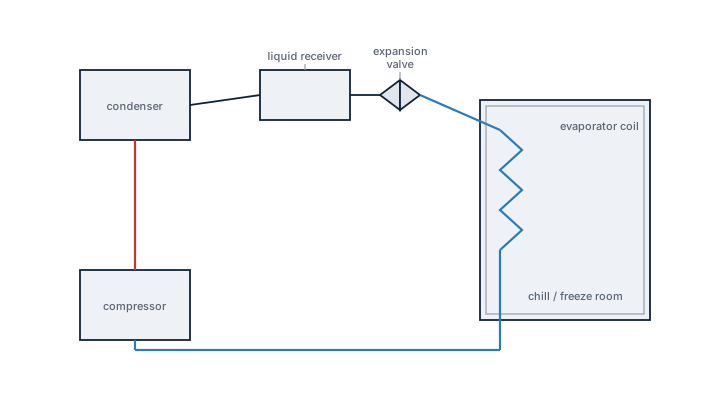
Provision cooling plant, refrigeration cycle
System flow of a provision cooling plant: compressor, condenser, liquid receiver and thermostatic expansion valve feeding the evaporator coil in the chill and freeze room, with hot discharge gas and cold suction gas shown by line colour, closing the loop back to the compressor.

Main components

Compressor set

Usually two or more compressors, run singly or staged together depending on load, so the plant can meet peak demand after loading provisions while idling on one machine for most of the voyage.

Condensing arrangement

A seawater-cooled shell-and-tube condenser is common on larger vessels, rejecting heat to the sea; smaller installations may use air-cooled condensers, which are more exposed to ambient temperature swings.

Room distribution and controls

Liquid refrigerant is distributed to each room's evaporator through solenoid valves controlled by individual room thermostats, so rooms cycle independently while sharing the compressor and condenser capacity.

Defrost system

Freeze room evaporators ice up in normal operation and need periodic defrosting, either by electric heater elements, hot gas, or a scheduled stop, to keep airflow across the coil and maintain capacity.

Selection and sizing

Plant capacity is set against the total heat load of all rooms served plus the highest expected simultaneous demand, commonly right after provisioning in port when warm product first enters the rooms. Redundancy is built in at the compressor level as described for that component, but the condenser and piping layout also need enough capacity margin that losing one compressor does not simply shift the bottleneck downstream. Insulation standard and door design for the rooms themselves affect plant sizing as much as the mechanical equipment - poorly insulated or badly sealed rooms force the plant to run harder for the same result.

Regulations and class

The plant's refrigerant is subject to the same Montreal Protocol and greenhouse gas phase-down considerations noted for the compressor, applied at the system level - total charge, leak rate over the plant as a whole, and the refrigerant log covering every room served. Class societies survey pressure vessels, safety valves and piping as part of the periodic refrigeration plant survey, and food safety inspections by port health authorities separately check that room temperatures and hygiene meet the standard expected for the product stored, which is an operational check on top of the mechanical survey.

Typical faults

FaultCauseConsequence
Uneven cooling between roomsA stuck or leaking solenoid valve diverting refrigerant unevenlyOne room runs warm while another overcools, risking product quality in both
Ice buildup beyond normal defrost capacityDefrost heater failure or defrost cycle not running on scheduleReduced airflow across the coil and a gradual rise in room temperature
Plant-wide low capacityCondenser fouling or low refrigerant charge affecting the whole systemEvery room served struggles to reach setpoint simultaneously
Door seal failureWorn gasket or door left ajarWarm, humid air ingress overloading the evaporator and forming ice faster

What to look for in a supplier

  • A system design showing how each room's load was calculated, not just a total compressor horsepower figure.
  • Defrost control strategy suited to the vessel's trading pattern, since frequent tropical port calls load the freeze rooms differently than a long ocean passage.
  • Spare parts support across the whole plant - solenoid valves, defrost heaters, and condenser tube bundles - not just the compressor.
  • Commissioning documentation that records baseline pull-down times and running pressures, useful later for diagnosing why the plant is underperforming.

Treat a slow pull-down after provisioning as a plant-level symptom first - check condenser seawater flow and overall refrigerant charge before assuming the problem is a single faulty compressor.

20 yr
Typical Lifetime

Typical Manufacturers

Carrier Bitzer Sabroe (Johnson Controls)

1 manufacturers · 3 models

Carrier Marine

3
Carrier Provision 30 unverified
105 kW cooling · 30.0 kW
System type
provision cooling plant
Cooling Capacity (kW)
105.0
Refrigerant
R-404A
Application
ship provision stores
Common Failures & Inspection Points
  • Loss of lubrication or poor oil return caused by low oil level, refrigerant migration or system faults, resulting in bearing noise, high temperature or compressor damage
  • Internal compression-element or valve wear caused by contamination, liquid carry-over or long service, resulting in poor capacity and abnormal discharge conditions
  • Refrigerant leakage caused by shaft seal, gasket or connection deterioration, resulting in loss of charge and reduced refrigeration performance
  • Liquid refrigerant return caused by poor superheat control or evaporator problems, resulting in knocking, oil dilution, abnormal vibration or mechanical damage
  • Motor, coupling or capacity-control fault caused by electrical or mechanical defects, resulting in trips, unstable suction pressure or inability to match load
Service: Monitor suction and discharge conditions, oil level, oil pressure where applicable, temperatures, vibration and compressor loading. Check for refrigerant and oil leakage and verify oil-management equipment operates as designed. Inspect couplings, filters, strainers and capacity-control mechanisms where fitted. Investigate any evidence of liquid return or repeated protective trips before restarting. Maintain system cleanliness and use only refrigerant and lubricant approved for the installed design. Refer to the manufacturer documentation for the exact figure for operating limits, clearances and overhaul procedures.
Spare Parts: Keep model-correct seals, gaskets, oil filters or strainers, approved lubricant and manufacturer-recommended valve, bearing or capacity-control service parts. Critical cargo or provision refrigeration may justify additional compressor-specific wear parts. Confirm refrigerant compatibility and exact parts from manufacturer documentation.
Use Cases: Provision refrigeration, cargo cooling, HVAC chillers and other marine refrigeration or process-cooling systems.
Carrier Provision 60 unverified
210 kW cooling · 60.0 kW
System type
provision cooling plant
Cooling Capacity (kW)
210.0
Refrigerant
R-404A
Application
ship provision stores
Common Failures & Inspection Points
  • Loss of lubrication or poor oil return caused by low oil level, refrigerant migration or system faults, resulting in bearing noise, high temperature or compressor damage
  • Internal compression-element or valve wear caused by contamination, liquid carry-over or long service, resulting in poor capacity and abnormal discharge conditions
  • Refrigerant leakage caused by shaft seal, gasket or connection deterioration, resulting in loss of charge and reduced refrigeration performance
  • Liquid refrigerant return caused by poor superheat control or evaporator problems, resulting in knocking, oil dilution, abnormal vibration or mechanical damage
  • Motor, coupling or capacity-control fault caused by electrical or mechanical defects, resulting in trips, unstable suction pressure or inability to match load
Service: Monitor suction and discharge conditions, oil level, oil pressure where applicable, temperatures, vibration and compressor loading. Check for refrigerant and oil leakage and verify oil-management equipment operates as designed. Inspect couplings, filters, strainers and capacity-control mechanisms where fitted. Investigate any evidence of liquid return or repeated protective trips before restarting. Maintain system cleanliness and use only refrigerant and lubricant approved for the installed design. Refer to the manufacturer documentation for the exact figure for operating limits, clearances and overhaul procedures.
Spare Parts: Keep model-correct seals, gaskets, oil filters or strainers, approved lubricant and manufacturer-recommended valve, bearing or capacity-control service parts. Critical cargo or provision refrigeration may justify additional compressor-specific wear parts. Confirm refrigerant compatibility and exact parts from manufacturer documentation.
Use Cases: Provision refrigeration, cargo cooling, HVAC chillers and other marine refrigeration or process-cooling systems.
Carrier Provision 100 unverified
350 kW cooling · 100.0 kW
System type
provision cooling plant
Cooling Capacity (kW)
350.0
Refrigerant
R-404A
Application
ship provision stores
Common Failures & Inspection Points
  • Mechanical wear caused by inadequate lubrication, contamination or long service, resulting in rising vibration, noise or temperature
  • Seal or gasket deterioration caused by wear, corrosion or misalignment, resulting in visible leakage or loss of process containment
  • Flow restriction, cavitation or fouling caused by blocked passages or unsuitable operating conditions, resulting in reduced capacity and unstable performance
  • Motor, coupling or drive failure caused by electrical faults, misalignment or overload, resulting in trips, abnormal current or inability to reach normal speed
  • Sensor, control or protection failure caused by wiring, calibration or electronics faults, resulting in alarms, incorrect control response or shutdown
Service: Inspect bearings, lubrication, seals, couplings, foundations, process connections and protective devices. Trend vibration, temperature, pressure, flow and motor load where available and investigate deterioration from the established normal condition. Check for leakage, corrosion, fouling and abnormal mechanical contact. Function-test local and remote controls, alarms and shutdowns after maintenance. Maintain cleanliness during opening and reassembly. Refer to the manufacturer documentation for the exact figure for clearances, limits, settings and overhaul criteria.
Spare Parts: Keep model-correct seals, gaskets, bearings, filters or strainers, coupling parts, sensors and manufacturer-recommended wear components. Critical installations may justify a rotating assembly, motor or control module according to redundancy. Confirm all parts against the exact model and serial number.
Use Cases: It is used for provision refrigeration, cargo cooling and HVAC on merchant ships, passenger vessels, offshore units or other vessel types where this equipment category is fitted.