Tank Cleaning Machine
A tank cleaning machine drives one or more rotating jet nozzles through a programmed or continuous cycle inside a cargo tank, using the mechanical force of the water or chemical jet rather than manual scrubbing to strip residue off the tank internals.
Read more — Tank Cleaning Machine explained ▾
What sets a tank cleaning machine apart
Manual tank cleaning with hand-held hoses is slow, puts crew inside a potentially hazardous atmosphere for longer than necessary, and gives inconsistent coverage depending on who is holding the hose. A tank cleaning machine solves this by lowering a nozzle head into the tank through a deck-mounted fitting and driving it through a fixed or programmable pattern - vertical indexing combined with horizontal rotation - so the jet sweeps the entire internal surface in a repeatable sequence. Machines range from simple fixed-pattern rotary jets, cycling continuously through the same sweep, to programmable units that step through a defined sequence of vertical positions and dwell times, giving more even coverage on tanks with awkward internal structure like heating coils or deep webs.
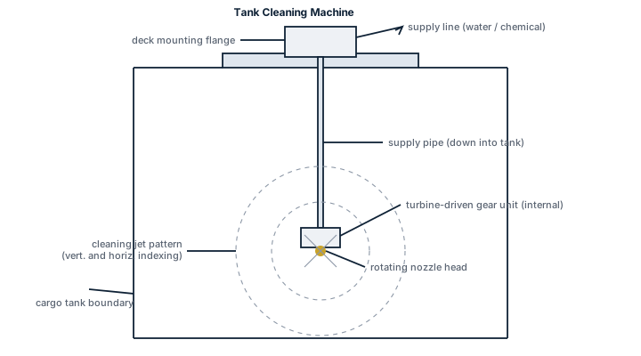
Main components
Deck fitting and drive
- Deck-mounted mounting flange or butterworth-type fitting, allowing the machine to be lowered into the tank without opening a full manhole
- Hydraulic or water-turbine drive unit, turning the nozzle head through its vertical and rotational pattern - hydraulic units are common where a chemical-resistant, non-sparking drive is needed
- Lowering wire or fixed lance, positioning the nozzle head at the correct depth in the tank
Nozzle head and control
- One or two opposed jet nozzles, sized for the flow rate and pressure the cleaning medium is supplied at
- Programme wheel or electronic controller on indexing units, setting the vertical step pattern and cycle time
- Non-sparking materials throughout the wetted parts on machines intended for cargo tanks that have carried flammable product, since a spark risk inside a tank being purged of vapour is unacceptable
Selection and sizing
Selection starts from tank geometry and internal structure - tank height, presence of heating coils, wash bulkheads or deep webs all affect whether a simple fixed-pattern machine gives adequate coverage or a programmable indexing unit is needed to reach shadowed areas. Throw distance and jet pressure need to reach every internal surface from the mounting position without gaps, and supply flow and pressure need to match what the tank cleaning pump on deck can actually deliver, since an undersized supply starves the machine of the pressure its cleaning performance depends on.
Regulations and class
MARPOL Annex I and Annex II set out crude oil washing and prewash requirements for oil and chemical tankers respectively, and the tank cleaning machine is the equipment that carries those procedures out in practice - crude oil washing in particular is mandatory on most oil tankers as part of controlling operational oil discharge. Class and flag requirements for gas-free certification before tank entry sit alongside, not instead of, the cleaning procedure, since a tank can be visually clean and still unsafe to enter until atmosphere testing confirms it.
Typical faults
- Nozzle wear opening up the spray pattern, cause: abrasive residue passing through the jet, consequence: reduced throw distance and patchy coverage that leaves contamination behind
- Drive unit seal failure, cause: chemical attack on seal material not matched to the cargo washed, consequence: leakage into the tank or loss of drive torque partway through a cycle
- Indexing mechanism sticking at one position, cause: residue buildup in the programme wheel or gearing, consequence: uneven coverage with the same area washed repeatedly while others are missed
- Lowering wire or lance corrosion, cause: exposure to cargo vapour and wash chemicals without adequate material selection, consequence: risk of the machine dropping or jamming inside the tank
What to look for in a supplier
- Wetted-part material compatibility with the actual cargo range the vessel trades, particularly for chemical tankers washing a variety of products
- Non-sparking certification for machines used in flammable cargo tanks, with documentation available for class and vetting inspections
- Nozzle and seal spares held as routine stock, since these are the wear parts that fail mid-voyage and cannot wait for a port call to source
- Compatibility with the existing deck tank cleaning line pressure and flow, rather than a machine that needs a pump upgrade to perform as rated
Match cleaning medium temperature and chemical dosing to what the machine's seals and wetted parts are actually rated for - a wash programme borrowed from a different cargo without checking machine compatibility is how a drive unit seal fails halfway through a wash.
2 manufacturers · 2 models
Alfa Laval
1
- BW-75
- BW-100
- BW-150
- Durchsatzbereich
- i40 S: 3-56 m³/h | i40 D: 7-80 m³/h | TZ-82: 15 m³/h (8mm-Düsen @ 7 bar)
- Betriebsdruck
- Typischerweise 4-12 bar; empfohlener Betriebsdruck 5-6,5 bar
- Wurfweite/reichweite
- TZ-82: 26 Meter horizontale Wurfweite (Benetzungsradius)
- Düsendurchmesser-Bereich
- 7-10 mm (verschiedene Konfigurationen für Durchsatz-Optimierung)
- Deck-Öffnung erforderlich
- i40 S/i40 D: nur 145 mm (kompakteste 2. Generation)
- Material-standard
- AISI 316 Edelstahl für Hauptkomponenten; PEEK für Seals/Verschleißteile
- Betriebstemperatur
- 0–95°C (32–203°F)
- Antriebsart
- Turbine-driven by cleaning medium flow (COW: crude oil washthrough possible)
- IMO-Konformität
- Erfüllt IMO-Anforderungen für COW (Crude Oil Washing) Systeme
- i40 S (Single-Nozzle, 2. Generation)
- i40 D (Dual-Nozzle, 2. Generation)
- i65 S (Single-Nozzle, High-Impact)
- T-73 (Automatic, 5.000-30.000 m³)
- TZ-67 (Rotary Jet Head, 50-500 m³)
- TZ-75 (Portable, 1.000-5.000 m³)
- TZ-82 (Portable/Fixed, bis 3.000 m³)
- TZ-89 (Media-Lubricated)
- 270FT Mark I (Single-Nozzle Crude Oil Tanker)
- Area: Nozzle wear and erosionCheck: Inspectors regularly check nozzles for wear marks, scratches, surface erosion and deformed openings. Nozzle blockages from sludge accumulation are the most frequent periodic maintenance task. Damaged nozzles must be replaced as a group.
- Area: Gearbox/turbine wear and vibrationCheck: Inspectors monitor for abnormal vibrations, temperature rise and irregular noise. Detached gear teeth and uneven disk distribution cause vibration problems. Inspection recommended every 200-300 operating hours; bearing replacement after 300-500 hours or at least every 3 years.
- Area: Ball bearings and sleeve bushings wearCheck: Inspectors check ball bearings for free rotation without contamination and damage. Sleeve bushings in gearbox frame must be checked: maximum diameter not exceeding 10.4 mm (bore not ovally deformed). Inspect all bearings and sealing rings every 6 months; replacement after 6,000 operating hours or every 3 years.
- Area: Seals and shaft passages (hysteresis coupling design)Check: Inspectors check for oil leakage and contamination at seal points. The hysteresis coupling eliminates conventional speed-setting shafts and reduces leak points. All rubber seals should be replaced at each service inspection to ensure hygiene and performance. Moisture and contamination ingress leads to seal failure.
- Area: Programming pattern and control sequence functionalityCheck: Inspectors test programming logic and valve control for correct 3D-indexed impact pattern. Check creep movement (vertical screw movement while horizontal rotation occurs) and progressive compression from coarse to fine over 8 cycles.
- Area: COW (Crude Oil Washing) system approval and crude oil compatibilityCheck: Inspectors verify IMO certification and crude oil wash-through approval. Toftejorg T-73 and 270FT Mark I are specifically designed for crude oil tankers. Check for corrosion/wear from crude oil exposure and verify valve seals under crude oil operating conditions.
Universal inspection/service points for tank cleaning machines (Gunclean Toftejorg, 2026-06). Per-model specs not auto-filled.
Scanjet Marine (Sweden)
1- SC-15
- SC-30
- SC-50
- SC-75
- Nozzle erosion from abrasive cargo residues
- Gear drive mechanism wear causing pattern failure
- Seal failure causing leak at tank penetration
- Drive turbine blade erosion from COW operation