Frequency Converter
A frequency converter changes an AC motor's speed by varying the frequency and voltage supplied to it, which is why a pump or fan running through one draws far less starting current and far less average power than the same motor run direct-on-line and throttled mechanically.
Read more — Frequency Converter explained ▾
What defines this type
A frequency converter, or variable frequency drive, sits between the ship's power supply and an AC motor and generates a variable-frequency, variable-voltage output that lets the motor run at any speed within its design range rather than only at the fixed speed set by the supply frequency. This is fundamentally different from a soft starter, which only ramps voltage during starting and then passes the motor straight through to full line frequency; a frequency converter controls speed continuously throughout the run, not just at start-up.
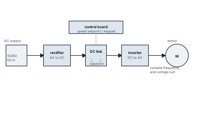
Main components
Rectifier stage
Converts the incoming AC supply to DC, usually with a diode bridge on standard units or an active front end on regenerative designs that can feed energy back to the ship's network during braking.
DC link
A capacitor bank, sometimes with an inductor, that smooths the rectified DC and decouples the input and output stages electrically.
Inverter stage
Insulated-gate bipolar transistors (IGBTs) switching the DC link at high frequency to synthesise a variable-frequency AC output using pulse-width modulation.
Control electronics and filters
The controller that manages the switching pattern and any protection functions, plus input and output filters needed to limit harmonic distortion fed back into the ship's electrical network and to protect motor windings and cabling from voltage spikes caused by fast switching.
Selection and sizing
Sizing is based on the driven load's power and starting torque requirement, not simply the motor's nameplate kW; a variable-torque load like a centrifugal pump or fan needs far less starting torque than a constant-torque load like a positive displacement pump or a winch. Harmonic distortion the converter injects back into the ship's switchboard has to stay within the limits the electrical system design allows, which becomes a real constraint when several large drives share one generator. Output cable length and type also matter more than with a direct-on-line motor, since the fast switching edges from the inverter stage can cause voltage reflection problems on long cable runs unless output filters or specific cable types are used.
Regulations and class
Class societies apply their electrical installation rules to frequency converters as they do to other power electronics, covering enclosure protection, cooling, and electromagnetic compatibility with navigation and communication equipment. Where a converter feeds a load classed as essential for propulsion or safety, redundancy and failure-mode requirements from the class rules for essential services apply, which can mean a bypass arrangement to run the motor direct-on-line if the converter fails.
Typical faults
| Fault | Cause | Consequence |
|---|---|---|
| Nuisance overcurrent trips | Cooling fan or heatsink fouled with dust or salt-laden air, causing thermal derating | Loss of drive availability, often intermittent and hard to diagnose from the fault log alone |
| DC link capacitor failure | Age-related capacitor degradation, accelerated by high ambient temperature | Complete loss of the converter, usually with no partial-function fallback |
| Motor bearing damage | Shaft currents induced by the high-frequency switching, without proper bearing insulation or shaft grounding | Premature bearing failure unrelated to mechanical load or lubrication |
| Harmonic distortion tripping other equipment | Undersized or missing input filter for the number of drives on the switchboard | Disturbance to sensitive electronic equipment sharing the same power supply |
What to look for in a supplier
- Rated output current and overload capability matched to the driven load's actual starting and running torque, not just steady-state power
- Documented harmonic performance and any filtering included, checked against the ship's switchboard capacity
- Enclosure protection rating and cooling arrangement suited to the installation space's temperature and contamination level
- Spare parts strategy for the specific power module and control board, since drive electronics are rarely field-repairable component by component
Keep a spare set of cooling fans on board for every drive of this type — fan failure from salt air is one of the most common causes of an otherwise healthy converter tripping on overtemperature.
3 manufacturers · 3 models
ABB
1- ACS800-07
- ACS880-07
- ACS880-17
- ACS6000
- 1
- 10000
- IGBT module failure from voltage spikes/overload
- Cooling fan failure causing thermal shutdown
- DC link capacitor aging
- LCL filter inductor overheating
- Communication bus errors with PMS/automation
Danfoss (Denmark)
1
- VLT FC102
- VLT FC302
- VLT AQUA Drive
- 0.5
- 1000
- IGBT failure from voltage transients
- PCB corrosion from humidity despite conformal coating
- Fan failure
- Parameter loss from EEPROM failure
Siemens
1- SINAMICS G120
- SINAMICS S120
- SINAMICS S150
- 1
- 5000
- IGBT failure
- Fan failure
- Capacitor aging
- Communication errors