Switchboard/MCC
The main switchboard is where every generator's output meets every consumer's demand, and the motor control centre extends that same busbar down to individual starters, which is why a fault at either point can black out sections the crew never expected to lose.
Read more — Switchboard/MCC explained ▾
What makes this type
The main switchboard is the busbar and breaker assembly that generators feed into and that distribution boards draw from; the motor control centre (MCC) is a related but distinct assembly, usually downstream of the switchboard, dedicated to housing individual motor starters for pumps, fans and other rotating machinery. Where the switchboard's job is bulk power handling and generator synchronising, the MCC's job is starting, protecting and controlling many individual motors from one compact, centrally wired location rather than scattering starters around the ship next to each motor.
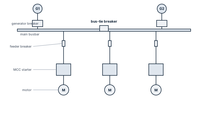
Main components
Busbars
Copper or aluminium bars carrying the full generated current, split into sections by bus-tie breakers so a fault on one section does not necessarily black out the other.
Generator and bus-tie breakers
Circuit breakers with synchronising and protection relays that allow generators to be paralleled safely and sections to be tied or split.
Feeder breakers
Individual breakers feeding distribution boards, large consumers and, in the MCC, each motor starter.
Motor starters
Direct-on-line, star-delta or soft-start units, each with overload protection sized to its motor, housed in individual withdrawable or fixed cubicles within the MCC.
Protection relays
Overcurrent, earth fault, reverse power and under/over voltage protection coordinated across switchboard and MCC so a downstream fault trips the nearest breaker first, not the generator breaker.
Selection / sizing
- Total generated capacity and expected load growth, setting busbar current rating with margin.
- Short-circuit fault level the busbar and breakers must withstand, calculated from the generator set's characteristics.
- Number and rating of motor starters needed in the MCC, driven by the machinery list rather than a standard module count.
- Degree of sectionalising (single, split, or fully redundant busbar) matched to the vessel's required level of electrical resilience.
Regulations / Class
SOLAS Ch. II-1 sets requirements for electrical installations including the arrangement of the main switchboard relative to the emergency switchboard and the protection against a single fault disabling both. Class rules require protective device coordination studies (selectivity) to be submitted and verified, and periodic testing of breaker trip settings and insulation resistance is carried out at survey. IACS unified requirements cover short-circuit withstand and type testing of switchgear assemblies.
Typical faults
| Fault | Cause | Consequence |
|---|---|---|
| Protection miscoordination | Relay settings changed locally without updating the selectivity study | Generator breaker trips for a fault that should have been cleared by a feeder breaker, blacking out the whole board |
| Busbar contact overheating | Loose connection or corroded joint | Progressive resistance rise, local burning, risk of fire inside the switchboard |
| Starter overload trip | Motor overload setting too tight or too loose for actual running current | Nuisance trips or, if too loose, undetected motor overheating |
| Insulation degradation | Moisture or dust ingress into an aging cubicle | Reduced insulation resistance, risk of earth fault or flashover |
What to look for in a supplier
- A documented selectivity and short-circuit study delivered with the switchboard, not just the hardware.
- Withdrawable breaker and starter modules where maintenance access without a full shutdown matters to the vessel's operating profile.
- Spares support for individual starter modules, since a single failed starter should not require sourcing an entire MCC section.
After any local change to a breaker or overload setting, update and re-check the selectivity study. An unrecorded setting change is the most common reason a small downstream fault takes down the whole switchboard instead of just one feeder.
3 manufacturers · 3 models
ABB
1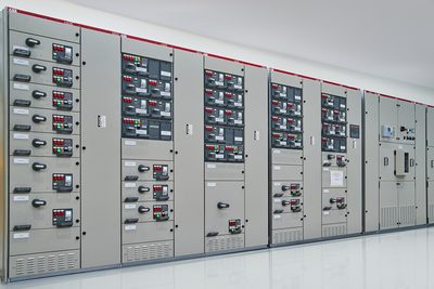
- MSB 440V
- MSB 690V
- MSB 6.6kV
- MSB 11kV
- Air Circuit Breaker (ACB) trip mechanism failure after 10,000+ operations
- Bus bar insulation degradation from age/moisture
- Protection relay calibration drift
- Contactor coil burnout from voltage fluctuations
- Earth fault on bus bar from insulation breakdown
Siemens
1
- LV Switchboard
- MV Switchboard
- Vacuum Circuit Breaker (VCB) contact wear
- Protection relay communication failure
- Bus bar insulation degradation
- Contactor failures
Wärtsilä
1
- LV MSB
- MV MSB
- ACB mechanism issues
- Bus bar insulation
- Protection relay drift