Gas Detection (Cargo Area)
Fixed gas detection in the cargo area has to catch a flammable hydrocarbon leak and a toxic or oxygen-depleting one at the same time, which is why cargo area detector heads nearly always pair an LEL sensor with a separate oxygen or toxic gas cell.
Read more — Gas Detection (Cargo Area) explained ▾
What cargo area gas detection has to catch
A gas carrier's cargo area presents two separate hazards at once: a flammable hydrocarbon leak that can reach its lower explosive limit (LEL), and, depending on the cargo, a toxic or asphyxiating atmosphere from the gas itself or from an inert blanket displacing oxygen. Fixed detection in the cargo area is designed around both, typically pairing a catalytic bead or infrared sensor for percentage-LEL readings with a separate electrochemical cell for oxygen or the specific toxic gas the cargo grade requires, such as ammonia or hydrogen sulphide on the relevant cargoes.

Main components
Detector heads
Distributed across the deck, in the cargo compressor room, cargo pump rooms, void spaces around cargo tanks, and at points of high leak probability such as manifold connections and vent risers. Placement follows the ship's hazardous area drawing, not a uniform grid.
Sample-draw versus diffusion (point) detectors
Enclosed or hard-to-access spaces often use sample-draw systems, where a pump pulls air through tubing to a central analyser cycling between multiple sample points. Open deck areas more often use diffusion-type point detectors that respond directly to gas reaching the sensor head, giving a faster response where continuous airflow can be relied on.
Control panel and cause-and-effect matrix
Ties every detector to a defined action: first alarm at a low percentage of LEL, second alarm and automatic trip of cargo operations, compressor shutdown, or ventilation fan stop at a higher threshold. This cause-and-effect matrix is specific to the ship and is what the officer of the watch and cargo control room actually rely on during operations, more than the raw sensor reading itself.
Selection considerations
| Parameter | Typical figure |
|---|---|
| First alarm setpoint | ~20-30% LEL |
| Second alarm / trip setpoint | ~50-60% LEL |
| Oxygen deficiency alarm | ~19.5% O2 |
| Response time, diffusion type | Seconds to under a minute |
Regulations and class
The IGC Code sets out required fixed gas detection coverage for cargo areas on gas carriers, tied to the specific cargoes the ship is certified to carry, and links detector alarms to prescribed automatic actions such as ventilation shutdown or cargo operation trips. Class surveys verify detector calibration records, response to test gas at each head, and that the cause-and-effect matrix in the control system matches the ship's approved documentation, not just that the panel powers up and shows normal.
Typical faults
| Fault | Consequence |
|---|---|
| Sensor drift between calibrations | False alarms, or worse, a real leak read as below alarm threshold |
| Sample line blocked or crushed | Sample-draw detector reports a fault or a falsely clean reading from that point |
| Detector head sited outside the actual leak path after a piping modification | Coverage gap that the original hazardous area study no longer reflects |
| Calibration gas cylinder expired or wrong gas mix used | Test result looks fine but does not verify the sensor against the real target gas |
What to look for in a supplier
- Sensor types matched to the specific cargo grades on the ship's certificate of fitness, not a generic hydrocarbon-only package
- Calibration and test gas support available at the ports the ship trades to
- Cause-and-effect logic that can be reviewed and updated if the ship's cargo certificate or piping changes
- Detector heads rated for the actual hazardous area zone at each mounting location, not a single certification across the board
Check the calibration date and test gas certificate on every head during handover, not just the panel's self-diagnostic; a detector can show green on the panel and still be reading a stale calibration from months earlier.
4 manufacturers · 6 models
Dräger
3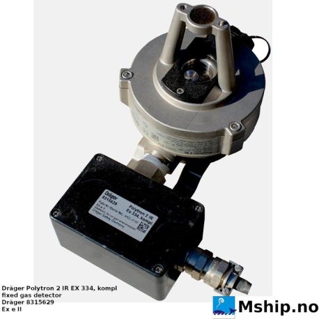
- IR window contamination
- Electronics failure
- Heated sensor malfunction
- High selectivity for hydrocarbons with low cross‑sensitivity to other gases
- No sensor poisoning; IR cell remains stable over long periods
- Built‑in self‑test and diagnostics reduce downtime
- Can be integrated into ship automation systems for remote monitoring
- Proven track record on LPG/LNG carriers
- IR window can become contaminated, requiring annual cleaning
- Heated sensor consumes power and may fail in extreme humidity
- Limited to hydrocarbon detection – does not monitor oxygen or CO₂
- Higher initial cost compared with electro‑chemical detectors
- Requires periodic calibration to maintain accuracy
- Process fouling or icing caused by cargo conditions, contamination or inadequate heating, resulting in reduced flow or unstable vaporization
- Seal or connection leakage caused by thermal cycling, corrosion or wear, resulting in gas detection, pressure loss or visible frost
- Sensor or analyzer drift where monitoring is involved caused by contamination or calibration faults, resulting in unreliable gas readings
- Valve or control failure caused by actuator, wiring or icing problems, resulting in unstable cargo flow or protective shutdown
- Material or heat-transfer surface damage caused by thermal stress or incompatible service, resulting in leakage, reduced duty or inspection findings
- Seal, gasket or process-connection leakage caused by wear, thermal cycling, corrosion or cargo incompatibility, resulting in cargo or vapor leakage
- Valve, actuator, pump or drive failure caused by sticking, wear, electrical or hydraulic faults, resulting in incorrect routing or reduced cargo-handling capacity
- Sensor or measuring-element fouling or drift caused by cargo deposits, contamination or calibration error, resulting in implausible readings or alarms
- Process fouling, icing or blockage caused by cargo residue, temperature conditions or debris, resulting in restricted flow or unstable operation
- Control, shutdown or hazardous-area electrical fault caused by wiring, electronics or configuration problems, resulting in unavailable remote operation or protective trips
MSA
1- Sensor poisoning
- Calibration drift
- 4-20mA signal fault
- Housing corrosion
- Dual sensor option (IR or catalytic) allows selection based on gas type and environment
- Marine‑grade housing designed for harsh shipboard conditions
- Standard 4‑20 mA analog signal integrates easily with existing alarm panels
- Built‑in self‑diagnostic alarms meet IMO SOLAS requirements
- Straightforward quarterly calibration procedure
- Sensor poisoning can occur in high humidity or oil‑mist areas common on tankers
- Calibration drift may require frequent maintenance visits
- Housing corrosion reported if protective coatings are not maintained
- Long analog wiring runs need proper shielding to avoid signal loss
- Fixed installation only; no portable backup unit
Oldham
1- Seal, gasket or process-connection leakage caused by wear, thermal cycling, corrosion or cargo incompatibility, resulting in cargo or vapor leakage
- Valve, actuator, pump or drive failure caused by sticking, wear, electrical or hydraulic faults, resulting in incorrect routing or reduced cargo-handling capacity
- Sensor or measuring-element fouling or drift caused by cargo deposits, contamination or calibration error, resulting in implausible readings or alarms
- Process fouling, icing or blockage caused by cargo residue, temperature conditions or debris, resulting in restricted flow or unstable operation
- Control, shutdown or hazardous-area electrical fault caused by wiring, electronics or configuration problems, resulting in unavailable remote operation or protective trips
Simtronics
1- Sample line blockage
- Pump failure
- Sensor degradation
- Condensation in sample lines
- Provides coverage of several points within each cargo tank, improving early leak detection.
- Integrated pump with automatic purge reduces manual line cleaning and maintenance frequency.
- Alarm hierarchy complies with SOLAS/IMO requirements for gas carrier safety systems.
- Modular design allows straightforward installation and future expansion.
- Sample‑line blockage can cause false alarms; lines must be purged regularly.
- Pump failure disables sampling until repaired, creating a temporary blind spot.
- Sensor degradation over time requires periodic calibration or replacement.
- Condensation in sample lines may affect measurement accuracy if not managed.