Reliquefaction Plant
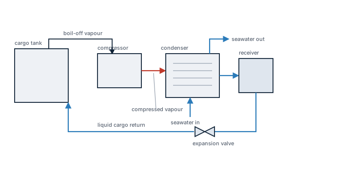
A reliquefaction plant compresses and cools cargo vapour back into liquid so a gas carrier can control tank pressure and boil-off without burning the cargo in a gas combustion unit or simply venting it, and the cycle it runs — direct compression or a cascade refrigerant loop — is dictated by how cold the cargo needs to stay.
Read more — Reliquefaction Plant explained ▾
What sets this plant apart
Every liquefied gas cargo boils off some vapour as heat leaks into the tank, and that vapour has to go somewhere. A gas combustion unit burns it as boiler fuel, which wastes cargo and only works while there is somewhere to burn it. A reliquefaction plant instead compresses the vapour, cools it, and returns it to the tank as liquid, holding tank pressure down and cargo quantity up over a long voyage. Which cycle it runs depends on the cargo: LPG at its atmospheric boiling point can often be reliquefied by direct compression and seawater or refrigerant-cooled condensing, while colder cargoes such as ethylene need a cascade cycle where a separate refrigerant loop reaches temperatures the cargo vapour alone cannot reject heat against.
Main components
- Cargo compressors – two or three stage reciprocating or screw compressors handling the boil-off gas, sized and staged for the pressure ratio the cargo and cycle demand.
- Condensers – seawater-cooled shell and tube units for direct-cycle cargoes, or refrigerant evaporators in a cascade system where a dedicated refrigerant (commonly R404A-type or ammonia-based on newer ships) does the final cooling.
- Economizers and separators – remove liquid slugs from the suction gas before it reaches the compressor, since liquid carryover is one of the most damaging events a reciprocating compressor can suffer.
- Cargo tank pressure control – instrumentation that starts, stops and modulates the plant to hold tank pressure inside the cargo's approved range.
- Deck seals (on some designs) – prevent backflow of vapour into the inert gas system when the plant is drawing down tank pressure.
Selection and sizing
Capacity is stated in tonnes of gas reliquefied per day and must cover the cargo's boil-off rate at the worst realistic combination of ambient temperature, voyage length and cargo fill level, with margin for a compressor or condenser being out of service. The choice between direct cycle and cascade cycle is fixed by the coldest cargo the ship is designed to carry, not by the average cargo, because retrofitting a cascade loop later is a major project.
Regulations and class
The IGC Code governs cargo containment and the associated cargo handling systems on gas carriers, including the pressure and temperature limits each cargo tank type is designed to hold and the relief valve arrangements that back up the reliquefaction plant if it cannot keep pace. Pressure vessels in the compressor and condenser trains fall under periodic class survey, and safety valves are function-tested and calibrated at set intervals.
Typical faults
| Fault | Consequence |
|---|---|
| Liquid slugging into the compressor from a saturated suction separator | Valve plate damage or, in severe cases, a hydraulic lock that can crack a cylinder head |
| Condenser fouling on the seawater side | Falling condensing capacity, rising tank pressure, and the plant unable to keep up in warm water |
| Refrigerant leakage in a cascade loop | Loss of the low-temperature stage needed for colder cargoes, forcing tank pressure to climb regardless of cargo compressor running hours |
| Undersized plant relative to the voyage plan | Tank pressure creeps up through a long ocean passage until the plant is running continuously with no margin left for a bad-weather slowdown |
What to look for in a supplier
- Rated capacity with a stated margin above calculated boil-off, not the bare minimum figure
- Compressor type matched to the cargo range – reciprocating machines tolerate a wider range of suction conditions than screw compressors on some services
- Spares support for the specific refrigerant used in a cascade loop, since not every port can supply every refrigerant type
- Documented compatibility with the full cargo list the vessel is certified to carry, not just the most common one
Running the plant flat out to chase a pressure spike is usually the wrong response; a steady, conservative reliquefaction rate through the voyage avoids the liquid-carryover risk that comes from pushing an already-cold system harder than its separators can handle.
3 manufacturers · 6 models
Cryostar
3Wärtsilä
2
- Compressor valve failure
- Expansion valve blockage
- Condenser fouling
- High reliquefaction efficiency with low power consumption
- Integrated control system compatible with Hamworthy/Wärtsilä LNG cargo handling equipment
- Modular design allows relatively easy installation and staged maintenance
- Proven operational record on a large number of LNG carriers worldwide
- Oil‑free compression reduces risk of oil contamination in the LNG product
- Complex valve train can lead to compressor valve failures or expansion‑valve blockages if not meticulously maintained
- Condenser fouling is a known issue requiring regular cleaning schedules
- Higher capital cost compared with simpler membrane‑type reliquefaction solutions
- Relatively large footprint and weight may limit suitability for smaller LNG vessels
- Requires skilled operators and dedicated maintenance crew to achieve optimal performance
- Compressor failure
- Heat exchanger fouling
- Control valve malfunction
- Refrigerant leak
- Proven reliability on a large fleet of LNG carriers
- Modular design allows quick replacement of the compressor during annual overhaul
- Low power consumption compared with turbo‑expander based systems
- Seamless integration with ship‑board LNG cargo handling and control systems
- Effective BOG reduction improves overall fuel efficiency
- Higher upfront capital cost than some alternative reliquefaction concepts
- Annual compressor overhaul required, increasing planned maintenance downtime
- Heat‑exchanger fouling can degrade performance if not regularly cleaned
- Control‑valve and refrigerant‑leak issues have been reported in service histories
- Requires skilled operators familiar with Wärtsilä control software
TGE Marine (MHI)
1
- Compressor bearing failure
- Heat exchanger scaling
- Control system malfunction
- Oil‑free screw compressors reduce contamination risk and lower maintenance intervals.
- Compact footprint allows installation on space‑constrained LNG carriers.
- Lower electrical power consumption compared with turbine‑driven reliquefiers.
- Integrated control system provides automatic BOG handling and real‑time monitoring.
- Proven performance on Japanese and German‑built LNG vessels with MHI service support.
- Compressor bearing wear has been reported, requiring periodic inspection.
- Heat‑exchanger scaling can occur if water treatment is inadequate.
- Control system complexity demands specialized training for operators.
- Higher initial capital cost than basic reliquefaction units.
- Typically supplied as a single train, offering limited redundancy.