Heading Repeater / Compass Repeater
A heading repeater carries no gyroscope of its own; it is a slave display driven by the master gyrocompass, and its only job is to put a true heading in front of the helmsman, the pelorus and the wing lookout at the same moment.
Read more — Heading Repeater / Compass Repeater explained ▾
What makes this type
A heading or compass repeater is a slave indicator that reproduces the heading generated by the master gyrocompass, not an independent sensor. This distinguishes it from the gyrocompass itself, which does the actual sensing, and from a magnetic compass, which is a standalone backup instrument. Repeaters exist because a single gyrocompass, usually mounted low in the ship for stability, cannot be read directly from the helm, the bridge wings or a pelorus stand, so its output is electrically or optically transmitted to multiple repeater positions around the vessel.

Main components
Repeater display unit
A dial or digital readout, at the steering position, chart table, bridge wings and often on the monkey island for taking visual bearings. Older systems use a synchro or stepper motor driven directly by the gyrocompass transmission; modern systems distribute heading digitally over a serial or network bus and drive each repeater electronically.
Transmission system
The wiring or network link between master gyrocompass and each repeater. In legacy synchro systems this is a dedicated multi-core cable per repeater; in networked systems a single bus can feed many repeaters, simplifying retrofit but concentrating failure risk on the bus itself.
Pelorus and bearing ring
Wing repeaters are commonly fitted with a pelorus ring for taking visual and radar bearings referenced to true heading, a function the bridge relies on for position fixing by terrestrial bearings.
Selection and sizing
- Compatibility with the ship's existing gyrocompass output format, synchro, step, or serial/network
- Number and location of repeater positions required by the ship's bridge layout and SOLAS carriage requirements
- Illumination and readability under both daylight and night bridge lighting conditions
- Backup power arrangement, since a repeater that goes dark on a power transfer defeats its purpose at the exact moment it may be needed
Regulations and class
SOLAS Chapter V requires ships above specified tonnage thresholds to be fitted with a gyrocompass and heading repeaters at the main steering position and, depending on ship type, at the bearing positions used for taking visual and radar bearings. Class societies verify repeater installation and function as part of the navigation equipment survey alongside the master gyrocompass itself.
Typical faults
| Fault | Consequence |
|---|---|
| Repeater heading drifting from master gyro reading | Helmsman steering to a wrong reference, and bearings taken at the wing repeater offset from true |
| Synchro motor wear on legacy systems | Sticking or lagging display, especially noticeable during rapid course changes |
| Corroded wing repeater housing from salt exposure | Intermittent display or complete failure at the exposed bearing position |
| Bus failure on networked repeater systems | Simultaneous loss of multiple repeaters rather than a single unit, a wider outage than legacy wiring would produce |
What to look for in a supplier
- Confirmed compatibility with the ship's specific gyrocompass output protocol before ordering a replacement or additional repeater
- Housing rated for exposed bridge wing conditions if the unit is destined for that position
- Spare parts availability for legacy synchro systems still common on older tonnage
Compare every wing repeater against the master gyro reading during the daily bridge equipment check, not just at survey time; a slow drift is easy to miss until a bearing taken from the wing is visibly wrong.
4 manufacturers · 4 models
Cassens & Plath
1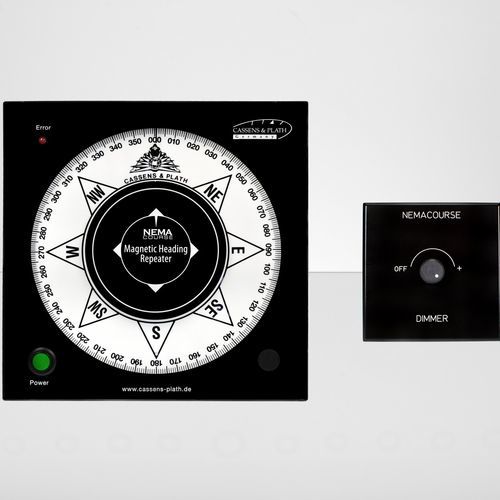
- Sensor, antenna or transducer fouling, damage or misalignment causes unstable, missing or inaccurate data
- Power-supply or processor faults cause resets, blank displays or complete loss of indication
- Cable, connector or network faults cause intermittent data or loss of outputs to dependent bridge systems
- Incorrect configuration or calibration causes persistent disagreement with independent references
- Display, storage or software faults cause frozen values, alarms or unavailable navigation functions
- Proven mechanical reliability with decades of service in the industry
- Simple, intuitive display – no software or screen failures
- Low power consumption and can operate from standard ship voltage without special wiring
- Provides an independent visual backup to electronic bridge displays
- Robust construction tolerates harsh marine environments
- Mechanical wear points (motor, gimbals) require periodic inspection and replacement
- Illumination typically uses incandescent bulbs that must be replaced regularly
- Limited resolution compared with modern digital heading displays
- Manual calibration may be needed after major repairs or alignment changes
- Not integrated into bridge management systems for remote monitoring
Observator
1
- Sensor, antenna or transducer fouling, damage or misalignment causes unstable, missing or inaccurate data
- Power-supply or processor faults cause resets, blank displays or complete loss of indication
- Cable, connector or network faults cause intermittent data or loss of outputs to dependent bridge systems
- Incorrect configuration or calibration causes persistent disagreement with independent references
- Display, storage or software faults cause frozen values, alarms or unavailable navigation functions
- Simple plug‑and‑play NMEA 0183 input from multiple heading sources
- Bright LED display with backlight for low‑light conditions
- Compact, weather‑proof housing suitable for bridge mounting
- Low power consumption compared to electromechanical repeaters
- Selectable source and alarm output for integration with bridge alarms
- Reported LED segment failures requiring screen replacement
- Occasional NMEA interface reliability problems in harsh EMI environments
- Mounting bracket design may need reinforcement on high‑vibration vessels
- Limited to NMEA 0183; no native NMEA 2000 or Ethernet connectivity
- No built‑in compass – depends entirely on external heading sensors
Raytheon Anschütz
1
- Sensor, antenna or transducer fouling, damage or misalignment causes unstable, missing or inaccurate data
- Power-supply or processor faults cause resets, blank displays or complete loss of indication
- Cable, connector or network faults cause intermittent data or loss of outputs to dependent bridge systems
- Incorrect configuration or calibration causes persistent disagreement with independent references
- Display, storage or software faults cause frozen values, alarms or unavailable navigation functions
- Directly linked to the primary ANS gyrocompass for exact heading synchronization
- Compact, low‑power LED display suitable for multiple installations on one ship
- Standardised connectors simplify wiring and integration with existing Anschütz systems
- Fast response time (sub‑second update) improves situational awareness during manoeuvres
- Built‑in self‑diagnostic messages help identify interface faults early
- Reliance on the central gyro means loss of heading display if the primary gyro or data bus fails
- LED modules can dim over time and require periodic replacement in high‑usage bridges
- Cable connector corrosion has been reported in harsh marine atmospheres, demanding regular inspection
- Limited redundancy compared with independent magnetic compass repeaters
- Proprietary stepper‑motor interface may need specialised spares from Raytheon Anschütz
YDK Technologies Co., Ltd., Morioka Branch
1