Steam Condenser
The steam condenser turns turbine or auxiliary exhaust back into feedwater by condensing it under vacuum against circulating seawater, and the vacuum itself, not just the cooling, is what lets the turbine produce useful work in the first place.
Read more — Steam Condenser explained ▾
What makes this type
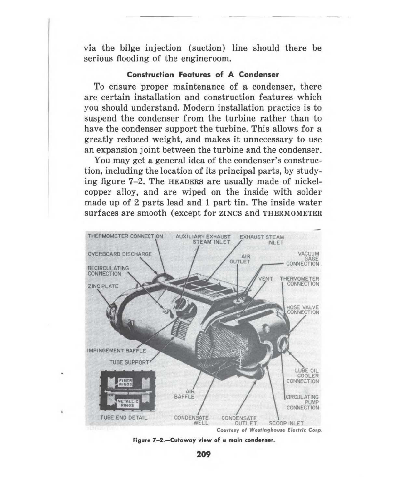
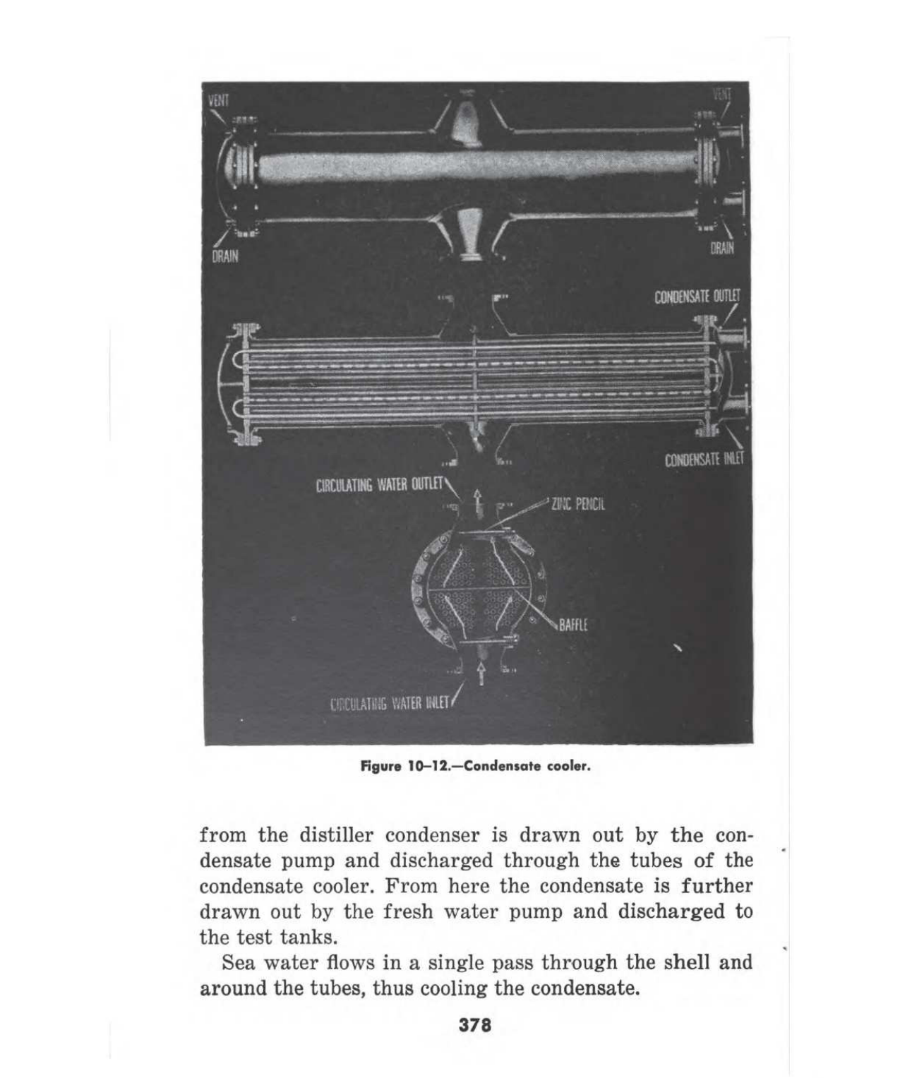
A steam condenser is a large shell-and-tube heat exchanger operating below atmospheric pressure. Exhaust steam enters the shell side and condenses on tube bundles carrying circulating seawater, while an air ejector or vacuum pump continuously removes non-condensable gases to hold the vacuum. The vacuum matters as much as the cooling: dropping the exhaust pressure below atmospheric increases the pressure differential across the turbine, which is what allows more work to be extracted from the same steam. This distinguishes it from other heat exchangers on board, which simply move heat without an operating pressure that affects the performance of the machine feeding them.

Main components
Tube bundle
Hundreds to thousands of thin-wall tubes, commonly titanium or cupronickel for seawater service, arranged to give maximum surface area in the available shell space.
Water boxes
End covers directing circulating seawater into and out of the tubes, fitted with access covers for tube plugging and cleaning.
Hotwell
The collection space at the bottom of the shell where condensed water gathers before being drawn off by the condensate extraction pump.
Air ejector or vacuum pump
Removes air and other non-condensable gases that accumulate on the steam side and would otherwise blanket the tubes and destroy the vacuum.
Circulating water pump
Draws seawater through the tube side, sized against the design temperature rise across the condenser.
Selection / sizing
- Design vacuum and corresponding saturation temperature, which sets how much work the turbine can recover.
- Circulating water flow rate and inlet temperature, since a warmer sea reduces achievable vacuum.
- Tube material selection against local seawater conditions, particularly where biofouling or erosion-corrosion is a known issue.
- Cleanliness factor assumed in the design, which degrades over the operating cycle between cleanings.
Regulations / Class
Class rules require periodic internal inspection of the condenser during survey, including tube plate and water box examination, as part of the boiler and steam plant survey regime rather than a standalone requirement. There is no dedicated SOLAS or MARPOL chapter for condensers specifically, though MARPOL Annex I governs any oily water discharge if a leak from lubricated machinery contaminates the condensate side.
Typical faults
| Fault | Cause | Consequence |
|---|---|---|
| Tube fouling | Marine growth or scale build-up on the seawater side | Reduced heat transfer, falling vacuum, higher fuel consumption for the same output |
| Tube leak | Erosion-corrosion or pitting at tube ends | Seawater contamination of feedwater, risk of boiler scaling or damage |
| Air ejector underperformance | Worn nozzles or steam supply pressure too low | Air accumulation blankets tubes, vacuum collapses gradually |
| Hotwell level control fault | Level sensor or extraction pump malfunction | Flooding of tube bundle or loss of suction to the extraction pump |
What to look for in a supplier
- Tube material recommendation backed by data on the vessel's actual trading waters, not a generic default.
- Guaranteed cleanliness factor and vacuum performance at stated seawater temperature and flow.
- Support for retubing services, since tube replacement rather than full condenser replacement is the usual repair route.
Watch vacuum trend, not just the instantaneous reading. A slow, steady fall over weeks is fouling that cleaning will fix, while a sudden drop points to an air ejector or tube leak that needs immediate attention.
Technical drawings & plates
Historical engineering archive — public domain sources, cited per plate. Principles shown remain valid; always consult the OEM manual for model-specific data.




Typical Manufacturers
4 manufacturers · 4 models
Alfa Laval
1
- Design Pressure M-Line
- >10 bar (145 psi)
- Marine Engine Room Modelle
- T6 (DN60, 800 kW) bis T35 (DN350, 35.000 kW)
- Marine FSRU Modelle
- TS45, T45, T50 (DN450-500, 45.000-55.000 kW)
- Temperaturbereich Standard
- 0–180°C (depending on model)
- FSRU Temperaturbereich
- -50 bis 150°C
- Plattentypen
- Chevron, Gemini Doppelwand, FlexFlow™
- M-Line (High Pressure Series: M3, M6, M10, M15)
- T-Series (Industrial: T2, T5, T6, T8, T10, T20, T25)
- AQ-Series (HVAC: AQ1, AQ2, AQ3, AQ4, AQ10)
- Marine Line (Engine Room: T6-T35; FSRU: TS45, T45, T50)
- Baseline (Competitive Line)
- Hygienic Line (Premium)
- Area: Gasket wear and embrittlementCheck: Inspect seals visually for cracks, hardening, swelling and discoloration; verify material compatibility with process fluids; check ClipGrip™ fastening. Aging symptoms and loss of elasticity are replacement indicators.
- Area: Clamping dimension and tightness (Tightening Dimension A)Check: Verify A-dimension per manufacturer specifications with caliper (metallic contact required). Keep bolts clean and lubricated. Avoid over-tightening. Perform regular re-tightening after operating hours. At too low A-dimension, pressure loss and leakage are to be expected.
- Area: Fouling and scale formation on plate surfacesCheck: Monitor pressure differential across heat exchanger (increase indicates deposits). Check heat duty versus design value. Optimize CIP intervals after performance audits. Deposits generate higher pump load (energy waste up to 8,000 kWh/year possible).
- Area: Plate corrosion and cracks / breakthroughsCheck: After disassembly, inspect plate surfaces for local measurements (pitting), cracks and perforation corrosion. Verify material compatibility with process fluid. Observe fatigue cracks especially at corners and transitions. When perforation occurs, plate is unrecoverable and must be replaced.
- Area: Pressure test and tightness inspectionCheck: After disassembly and cleaning, perform hydrostatic test per data sheet. Test pressure typically 1.5× operating pressure. Check external and internal leakage at all connections and plate edges. Document findings.
- Area: Plate sequence and alignment (5-point alignment)Check: After opening, verify plate sequence and honeycomb pattern (corrected chevron patterns must alternate). Activate/validate 5-point alignment system for larger units. Offset or misplacement leads to short-circuiting and reduced heat duty.
Type-universal inspection points for Alfa Laval Gasketed Plate Heat Exchangers (GPHE) (Alfa Laval, 2026-06). Per-model specs not auto-populated.
- High design pressure (>10 bar) suitable for modern high‑speed diesel and turbine plants
- Modular plate construction allows quick capacity changes and on‑site repairs
- Compact footprint compared with shell‑and‑tube condensers, saving valuable engine‑room space
- Standardised gasket system (ClipGrip™) simplifies seal replacement and reduces downtime
- Plate fouling can increase pressure drop; requires regular monitoring and cleaning in high‑salinity steam cycles
- Gasket material must be compatible with condensate chemistry – unsuitable fluids may cause premature wear
- Maximum capacity limited to the M‑Line series range; very large power plants may need multiple units or alternative designs
GEA
1
- Fouling or scaling increases differential pressure and reduces heat-transfer performance
- Gasket, seal or tube-joint deterioration causes external leakage
- Plate or tube corrosion, erosion or cracking causes internal cross-contamination between fluid circuits
- Blocked strainers or restricted valves reduce flow and produce abnormal inlet-to-outlet temperatures
- Incorrect reassembly, venting or flow distribution after service causes leakage or poor thermal performance
- High heat‑transfer area per unit volume gives excellent condensation performance.
- Compact footprint suited for vessels with restricted engine‑room space.
- Modular plate design allows quick inspection, cleaning and replacement of individual plates.
- Stainless‑steel or corrosion‑resistant plate material reduces long‑term degradation.
- Integrated with vacuum pump systems; oil level monitoring is straightforward.
- Gasket wear can lead to leaks if not inspected regularly.
- Plate fouling or corrosion accelerates maintenance needs when feedwater treatment is inadequate.
- Initial purchase price is higher than conventional shell‑and‑tube condensers.
- Requires a dedicated vacuum pump and regular oil level checks.
- Maximum steam capacity may be limited for very high‑power turbine applications.
Sasakura
1- Fouling or scaling increases differential pressure and reduces heat-transfer performance
- Gasket, seal or tube-joint deterioration causes external leakage
- Plate or tube corrosion, erosion or cracking causes internal cross-contamination between fluid circuits
- Blocked strainers or restricted valves reduce flow and produce abnormal inlet-to-outlet temperatures
- Incorrect reassembly, venting or flow distribution after service causes leakage or poor thermal performance
- Compact footprint suitable for vessels with limited engine‑room space
- High thermal efficiency due to optimized tube layout
- Robust construction with corrosion‑resistant tubing material
- Zinc anodes are easily replaceable during dry‑dock periods
- Proven reliability on a range of merchant ships
- Tube material can be prone to corrosion if water chemistry is not tightly controlled
- Vacuum performance degrades quickly with air ingress; requires vigilant sealing maintenance
- Periodic tube fouling necessitates scheduled cleaning at dry‑dock
- Initial purchase price higher than basic, non‑brand condensers
- Spare parts inventory may be limited in regions without a Sasakura dealer